EP3127857A1 - Vorrichtung zur betätigung einer lenkeinrichtung eines flurförderzeugs - Google Patents
Vorrichtung zur betätigung einer lenkeinrichtung eines flurförderzeugs Download PDFInfo
- Publication number
- EP3127857A1 EP3127857A1 EP16182380.2A EP16182380A EP3127857A1 EP 3127857 A1 EP3127857 A1 EP 3127857A1 EP 16182380 A EP16182380 A EP 16182380A EP 3127857 A1 EP3127857 A1 EP 3127857A1
- Authority
- EP
- European Patent Office
- Prior art keywords
- handle
- truck
- axis
- rotation
- actuating element
- Prior art date
- Legal status (The legal status is an assumption and is not a legal conclusion. Google has not performed a legal analysis and makes no representation as to the accuracy of the status listed.)
- Granted
Links
Images

Classifications
-
- B—PERFORMING OPERATIONS; TRANSPORTING
- B66—HOISTING; LIFTING; HAULING
- B66F—HOISTING, LIFTING, HAULING OR PUSHING, NOT OTHERWISE PROVIDED FOR, e.g. DEVICES WHICH APPLY A LIFTING OR PUSHING FORCE DIRECTLY TO THE SURFACE OF A LOAD
- B66F9/00—Devices for lifting or lowering bulky or heavy goods for loading or unloading purposes
- B66F9/06—Devices for lifting or lowering bulky or heavy goods for loading or unloading purposes movable, with their loads, on wheels or the like, e.g. fork-lift trucks
- B66F9/075—Constructional features or details
- B66F9/0759—Details of operating station, e.g. seats, levers, operator platforms, cabin suspension
Definitions
- a device for actuating a steering device of a truck with a handle has become known on which an operator can be supported with parts of the carpal and the middle hand of a hand.
- the known device also has a rotatable actuating element, which is arranged at a distance from the handle. It essentially rotates about a longitudinal axis of the handle and is operated with the thumb.
- the user can actuate the actuator optionally with only one finger or a finger combination deviating from the thumb and forefinger, for example only with the thumb, only with the index finger or with the index and middle fingers.
- the actuator optionally with only one finger or a finger combination deviating from the thumb and forefinger, for example only with the thumb, only with the index finger or with the index and middle fingers.
- he always has the option of using it with his thumb and index fingers, depending on the design in addition to reach with other fingers, especially the middle finger.
- the arrangement of the axis of rotation in said angular range relative to the longitudinal axis differs significantly from that of the document DE 198 49 235 B4 known device and allows the user to rotate the actuator with thumb and forefinger while he holds the handle enclosed. It is understood that the axis of rotation and the longitudinal axis do not necessarily intersect, but can also be arranged skewed to each other. The angle between the two axes is then defined as the angle between the associated directional vectors.
- the axis of rotation is arranged at an angle in the range of 75 ° to 105 ° to the longitudinal axis, in particular approximately at right angles thereto.
- Handle and actuator are arranged at a distance from each other.
- the fingers enclosing the handle can thus be arranged in particular between the handle and the actuating element.
- the handle may have a length of e.g. at least 8 cm.
- the distance between the handle and the actuator may suitably be in the range of 2 cm to 8 cm.
- a distance between the axis of rotation and the longitudinal axis is at most 5 cm. This distance is valid for a perpendicular to both axes connection, so possibly to the distance to an imaginary extension of the axis of rotation or the longitudinal axis.
- the distance between the axis of rotation and the longitudinal axis may be less than 5 cm, for example at most 4 cm or at most 3 cm. Depending on the size of the user's hand and the dimensions of the handle so a particularly ergonomic arrangement can be found.
- the axis of rotation passes through the handle.
- the handle may typically have a diameter in the range of 2 cm to 5 cm. It may be circular cylindrical or have a different cross-section. Runs the axis of rotation through the handle through, the actuator can be achieved particularly easily both with the index finger and with the thumb.
- the handle has a free end at which the handle is rounded.
- the other end of the handle can be attached to a body part or a control panel or to any other carrier of the truck.
- the handle has a diameter that increases toward the free end.
- the cross section of the handle can be circular or have a deviating geometry, for example, oval. The increasing diameter towards the free end counteracts slippage from the handle, so that the user finds particularly secure hold.
- the actuating element has a multiplicity of projections or depressions arranged radially relative to the axis of rotation.
- the actuating element basically have any basic shape, for example the shape of a disk.
- the projections or recesses arranged in particular on the outer circumference of the actuating element provide secure hold for the fingers with which the actuating element is to be moved.
- the projections may be, for example, wings or ribs in which depressions are around depressions.
- a particularly handy surface structure of the actuating element is considered, for example a corrugation, embossing or rubber coating.
- the actuating element has a zero position and there is a return device which automatically returns the actuating element to the zero position after rotation out of the zero position.
- the zero position corresponds to a straight ahead.
- the automatic return of the actuating element in the zero position can counteract incorrect operation and ensures when driving that the actuator is in a defined, familiar position.
- the device has a sensor which is designed to detect whether a user's hand is arranged on the handle. It may be, for example, an optical or capacitive sensor. With the help of the sensor can be monitored whether the user complies with an intended operating position. Otherwise, the truck may be completely or partially deactivated, in particular the traction drive of the truck.
- the device is part of an industrial truck, which also has a steering device which is controllable by rotating the actuating element.
- the longitudinal axis is arranged at an angle of 20 ° or less to the horizontal. The user can therefore support his palm in an approximately horizontal position on the handle, which is ergonomically advantageous.
- the longitudinal axis is arranged at an angle in the range of 60 ° to 90 ° to a main direction of travel of the truck. This is particularly handy, especially when the user drives in the main direction standing.
- a center of the actuating element is arranged in a main direction of travel of the truck in front of the longitudinal axis. If the user drives along in the manner mentioned on the truck, he can then reach the actuating element particularly easily.
- the axis of rotation is arranged at an angle of 30 ° or less to the vertical.
- the axis of rotation can be easily facing the user. This arrangement also contributes to a comfortable and safe operation of the actuator.
- the truck has a liftable platform with a lifting platform for an operator and the device for actuating the steering device is attached to the platform.
- the standing platform can be provided with a railing or basket or a cabin.
- the handle of the device according to the invention provides the operator with additional support, especially while driving or lifting.
- FIG. 1 recognizes a part of a control panel 10 of a truck.
- the control panel 10 has an approximately vertically disposed and a user-facing front side 12 and a Top having a horizontal surface 14 and an adjoining, slightly inclined and the user facing inclined surface 16.
- the handle 18 has a free end 20 which is rounded, and a located at the other end of the handle 18 mounting portion 22 which is fixed in the region of the inclined surface 16 on the control panel 10.
- the longitudinal axis 24 of the handle 18 is indicated by dash-dotted lines.
- the handle 18 has an approximately circular cylindrical cross-section and widens slightly towards the free end 20.
- an actuating element 26 which is rotatably mounted about a likewise dash-dotted lines indicated axis of rotation 28.
- the actuator 26 is also secured in the region of the inclined surface 16 on the control panel 10 and is located at a distance of a few centimeters from the handle 18.
- the longitudinal axis 24 of the handle 18 and the axis of rotation 28 of the actuating element 26 are skewed to each other.
- the angle between the longitudinal axis 24 and the axis of rotation 28 is about 90 °.
- the actuator 26 has a disc-shaped basic shape with four wings extending radially outwardly from the outer periphery of this basic shape, two of which are in the FIG. 1 are visible.
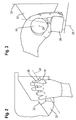
- FIGS. 2 and 3 the intended use device is illustrated.
- the embodiment of FIGS. 2 and 3 is different from the one of FIG. 1 in particular in that the handle 18 has a different attachment portion 22, which on a substantially vertically disposed surface 32 of the differently shaped control panel 10th is attached.
- the relative arrangement of the handle 18 to the actuator 26 substantially corresponds to that of the embodiment of FIG. 1
- the longitudinal axis 24 of the handle 18 is again illustrated by a dot-dash line.
- the rotation axis 28, not shown, is arranged approximately perpendicular to the plane of the drawing.
- the axis of rotation 28 of the actuator 26 is shown in phantom and the longitudinal axis 24 is arranged approximately perpendicular to the plane of the drawing. It can be seen that the axis of rotation 28 passes through the handle 18 therethrough.
- a user can rest with his palm on top of the handle 18 and enclose the handle 18 with at least one finger. In the FIGS. 2 and 3 he does this with the little finger, the ring finger and additionally with the thumb. With the index and middle fingers, he actuates the actuator 26. Alternatively, he could create his thumb on the side of the actuator 26 opposite the index and middle fingers.
Landscapes
- Engineering & Computer Science (AREA)
- Transportation (AREA)
- Structural Engineering (AREA)
- Civil Engineering (AREA)
- Life Sciences & Earth Sciences (AREA)
- Geology (AREA)
- Mechanical Engineering (AREA)
- Mechanical Control Devices (AREA)
Abstract
Description
- Zur Betätigung von Lenkeinrichtungen von Flurförderzeugen sind unter anderem Lenkräder unterschiedlicher Größe mit und ohne Knauf bekannt. Diese ermöglichen in der Regel eine intuitive und präzise Steuerung, benötigen jedoch relativ viel Platz. Insbesondere bei Flurförderzeugen, bei denen die Bedienperson stehend mitfährt und/oder gemeinsam mit einem Lasttragmittel angehoben wird, besteht eine weitere Anforderung darin, dass sich die Bedienperson während der Fahrt bequem und sicher festhalten kann.
- Aus der Druckschrift
EP 1 657 212 B1 ist ein Flurförderzeug mit einer anhebbaren Fahrerkabine bekannt geworden, in der die Bedienperson stehend mitfährt. Innerhalb der Fahrerkabine gibt es zwei Haltegriffe, an denen sich die Bedienperson festhalten und zugleich das Fahrzeug steuern kann. Zur Betätigung einer Lenkeinrichtung dient eine in einen der beiden Handgriffe integrierte Wippe, die relativ zu dem Handgriff schwenkbar ist. - Aus der Druckschrift
DE 198 49 235 B4 ist eine Vorrichtung zur Betätigung einer Lenkeinrichtung eines Flurförderzeugs mit einem Haltegriff bekannt geworden, auf dem sich eine Bedienperson mit Teilen der Handwurzel und der Mittelhand einer Hand abstützen kann. Die bekannte Vorrichtung hat außerdem ein drehbares Betätigungselement, das in einem Abstand von dem Haltegriff angeordnet ist. Es rotiert im Wesentlichen um eine Längsachse des Haltegriffs und wird mit dem Daumen betätigt. - Davon ausgehend ist es die Aufgabe der Erfindung, eine Vorrichtung zur Betätigung einer Lenkeinrichtung eines Flurförderzeugs zur Verfügung zu stellen, die eine sichere und präzise Betätigung der Lenkeinrichtung auch bei Erschütterungen des Fahrzeugs ermöglicht und an der sich die Bedienperson gleichzeitig gut festhalten kann.
- Diese Aufgabe wird gelöst durch die Vorrichtung mit den Merkmalen des Anspruchs 1. Vorteilhafte Ausgestaltungen sind in den sich anschließenden Unteransprüchen angegeben.
- Die Vorrichtung dient zur Betätigung einer Lenkeinrichtung eines Flurförderzeugs und hat
- einen Haltegriff, der eine Längsachse aufweist, und
- ein Betätigungselement, das in einem Abstand von dem Haltegriff angeordnet und relativ zu dem Haltegriff um eine Drehachse drehbar gelagert ist, wobei
- die Drehachse einen Winkel im Bereich von 60° bis 120° zu der Längsachse aufweist und das Betätigungselement und der Haltegriff so geformt und relativ zueinander angeordnet sind, dass ein Benutzer das Betätigungselement mindestens mit Daumen und Zeigefinger einer mit der Handinnenfläche auf dem Haltegriff aufliegenden Hand gleichzeitig erreichen kann, während er mit mindestens einem weiteren Finger derselben Hand den Haltegriff umschließt.
- Durch die genannte Anordnung des Haltegriffs kann ein Benutzer, während er eine Hand auf den Haltegriff auflegt und den Haltegriff mit mindestens einem Finger umschließt, sich also sicher festhält, das Betätigungselement mit Daumen und Zeigefinger erreichen. Er kann das Betätigungselement dadurch besonders sicher führen, auch bei Erschütterungen des Fahrzeugs.
- Es versteht sich, dass der Benutzer das Betätigungselement wahlweise auch nur mit einem Finger oder einer von Daumen und Zeigefinger abweichenden Fingerkombination betätigen kann, beispielsweise nur mit dem Daumen, nur mit dem Zeigefinger oder mit Zeige- und Mittelfinger. Er hat jedoch stets die Möglichkeit, es mit Daumen und Zeigefinger, je nach Ausgestaltung zusätzlich mit weiteren Fingern, insbesondere dem Mittelfinger, zu erreichen.
- Die Anordnung der Drehachse in dem genannten Winkelbereich relativ zu der Längsachse unterscheidet sich deutlich von der aus der Druckschrift
DE 198 49 235 B4 bekannten Vorrichtung und ermöglicht es dem Benutzer, das Betätigungselement mit Daumen und Zeigefinger zu drehen, während er den Haltegriff umschlossen hält. Es versteht sich, dass sich Drehachse und Längsachse nicht notwendigerweise schneiden, sondern auch windschief zueinander angeordnet sein können. Der Winkel zwischen den beiden Achsen ist dann definiert als Winkel zwischen den zugehörigen Richtungsvektoren. Bevorzugt ist die Drehachse in einem Winkel im Bereich von 75° bis 105° zu der Längsachse angeordnet, insbesondere etwa rechtwinklig dazu. - Haltegriff und Betätigungselement sind in einem Abstand voneinander angeordnet. Die den Haltegriff umschließenden Finger können also insbesondere zwischen Haltegriff und Betätigungselement angeordnet sein. Der Haltegriff kann eine Länge von z.B. mindestens 8 cm aufweisen. Der Abstand zwischen dem Haltegriff und dem Betätigungselement kann zweckmäßigerweise im Bereich von 2 cm bis 8 cm liegen.
- In einer Ausgestaltung beträgt ein Abstand zwischen der Drehachse und der Längsachse höchstens 5 cm. Dieses Abstandsmaß gilt für eine zu beiden Achsen senkrecht stehende Verbindung, also gegebenenfalls auf den Abstand zu einer gedachten Verlängerung der Drehachse bzw. der Längsachse. Wahlweise kann der Abstand zwischen Drehachse und Längsachse kleiner als 5 cm gewählt werden, beispielsweise höchstens 4 cm oder höchstens 3 cm betragen. Je nach Größe der Hand des Benutzers und den Abmessungen des Haltegriffs kann so eine besonders ergonomische Anordnung gefunden werden.
- In einer Ausgestaltung verläuft die Drehachse durch den Haltegriff hindurch. Der Haltegriff kann typischerweise einen Durchmesser im Bereich von 2 cm bis 5 cm aufweisen. Er kann kreiszylindrisch sein oder einen davon abweichenden Querschnitt aufweisen. Verläuft die Drehachse durch den Haltegriff hindurch, kann das Betätigungselement in der Regel besonders einfach sowohl mit dem Zeigefinger als auch mit dem Daumen erreicht werden.
- In einer Ausgestaltung weist der Haltegriff ein freies Ende auf, an dem der Haltegriff abgerundet ist. Das andere Ende des Haltegriffs kann an einem Karosserieteil oder einer Bedienkonsole oder an einem sonstigen Träger des Flurförderzeugs befestigt werden.
- In einer Ausgestaltung weist der Haltegriff einen Durchmesser auf, der sich in Richtung zu dem freien Ende hin vergrößert. Dabei kann der Querschnitt des Haltegriffs kreisförmig sein oder eine davon abweichende Geometrie aufweisen, beispielsweise oval. Der sich zum freien Ende hin vergrößernde Durchmesser wirkt einem Abrutschen von dem Haltegriff entgegen, sodass der Benutzer besonders sicher Halt findet.
- In einer Ausgestaltung weist das Betätigungselement eine Vielzahl von bezogen auf die Drehachse radial angeordneten Vorsprüngen oder Vertiefungen auf. Dabei kann das Betätigungselement grundsätzlich eine beliebige Grundform aufweisen, z.B. die Form einer Scheibe. Die insbesondere am äußeren Umfang des Betätigungselements angeordneten Vorsprünge oder Vertiefungen bieten den Fingern, mit denen das Betätigungselement bewegt werden soll, sicheren Halt. Bei den Vorsprüngen kann es sich beispielsweise um Flügel oder Rippen handeln, bei denen Vertiefungen um Mulden. Als Alternative zu ausgeprägten Vorsprüngen oder Vertiefungen kommt eine besonders griffgünstige Oberflächenstruktur des Betätigungselements in Betracht, beispielsweise eine Riffelung, Prägung oder Gummierung.
- In einer Ausgestaltung weist das Betätigungselement eine Nullstellung auf und es ist eine Rückführeinrichtung vorhanden, die das Betätigungselement nach einer Drehung aus der Nullstellung heraus automatisch in die Nullstellung zurückführt. Die Nullstellung entspricht einer Geradeausfahrt. Die automatische Rückführung des Betätigungselements in die Nullstellung kann Fehlbedienungen entgegenwirken und stellt bei Fahrtantritt sicher, dass sich das Betätigungselement in einer definierten, gewohnten Stellung befindet.
- In einer Ausgestaltung weist die Vorrichtung einen Sensor auf, der dazu ausgebildet ist, zu erfassen, ob eine Hand eines Benutzers am Haltegriff angeordnet ist. Es kann sich beispielsweise um einen optischen oder kapazitiven Sensor handeln. Mit Hilfe des Sensors kann überwacht werden, ob der Benutzer eine vorgesehene Bedienposition einhält. Anderenfalls kann das Flurförderzeug ganz oder teilweise deaktiviert werden, insbesondere der Fahrantrieb des Flurförderzeugs.
- In einer Ausgestaltung ist die Vorrichtung Teil eines Flurförderzeugs, das außerdem eine Lenkeinrichtung aufweist, die durch Drehen des Betätigungselements steuerbar ist.
- In einer Ausgestaltung des Flurförderzeugs ist die Längsachse in einem Winkel von 20° oder weniger zur Horizontalen angeordnet. Der Benutzer kann seine Handinnenfläche daher in einer annähernd waagerechten Stellung auf dem Haltegriff abstützen, was ergonomisch vorteilhaft ist.
- In einer Ausgestaltung des Flurförderzeugs ist die Längsachse in einem Winkel im Bereich von 60° bis 90° zu einer Hauptfahrtrichtung des Flurförderzeugs angeordnet. Dies ist besonders griffgünstig, insbesondere wenn der Benutzer in Hauptfahrtrichtung stehend mitfährt.
- In einer Ausgestaltung des Flurförderzeugs ist ein Mittelpunkt des Betätigungselements in einer Hauptfahrtrichtung des Flurförderzeugs vor der Längsachse angeordnet. Fährt der Benutzer in der genannten Art und Weise auf dem Flurförderzeug mit, kann er das Betätigungselement dann besonders einfach erreichen.
- In einer Ausgestaltung des Flurförderzeugs ist die Drehachse in einem Winkel von 30° oder weniger zur Vertikalen angeordnet. Insbesondere kann die Drehachse dem Benutzer leicht zugewandt sein. Auch diese Anordnung trägt zu einer bequemen und sicheren Bedienbarkeit des Betätigungselements bei.
- In einer Ausgestaltung weist das Flurförderzeug eine mit einer Hubvorrichtung anhebbare Standplattform für eine Bedienperson auf und die Vorrichtung zur Betätigung der Lenkvorrichtung ist an der Standplattform befestigt. Die Standplattform kann mit einem Geländer oder Korb oder einer Kabine versehen sein. Der Haltegriff der erfindungsgemäßen Vorrichtung bietet der Bedienperson zusätzlichen Halt, insbesondere während der Fahrt oder eines Hubvorgangs.
- Nachfolgend wird die Erfindung anhand von in Figuren dargestellten Ausführungsbeispielen näher erläutert. Es zeigen:
- Fig. 1
- ein erstes Ausführungsbeispiel einer erfindungsgemäßen Vorrichtung, montiert an einer Bedienkonsole,
- Fig. 2
- ein zweites Ausführungsbeispiel einer erfindungsgemäßen Vorrichtung mit der Hand eines Benutzers und Blickrichtung von oben, und
- Fig. 3
- die Anordnung aus
Fig. 2 in einer weiteren Ansicht von der Seite. - In der perspektivischen Darstellung der
Figur 1 erkennt man einen Teil einer Bedienkonsole 10 eines Flurförderzeugs. Die Bedienkonsole 10 hat eine etwa vertikal angeordnete und einem Benutzer zugewandte Frontseite 12 sowie eine Oberseite, die eine waagerechte Fläche 14 und eine sich daran anschließende, leicht geneigte und dem Benutzer zugewandte Schrägfläche 16 aufweist. - Der Haltegriff 18 hat ein freies Ende 20, das abgerundet ist, und einen sich am anderen Ende des Haltegriffs 18 befindenden Befestigungsabschnitt 22, der im Bereich der Schrägfläche 16 an der Bedienkonsole 10 befestigt ist. Die Längsachse 24 des Haltegriffs 18 ist strichpunktiert angedeutet. Der Haltegriff 18 hat einen annähernd kreiszylindrischen Querschnitt und weitet sich zum freien Ende 20 hin leicht auf.
- Unterhalb des Haltegriffs 18 und in der Ansicht der
Figur 1 davon teilweise verdeckt befindet sich ein Betätigungselement 26, das um eine ebenfalls strichpunktiert angedeutete Drehachse 28 drehbar gelagert ist. Das Betätigungselement 26 ist ebenfalls im Bereich der Schrägfläche 16 an der Bedienkonsole 10 befestigt und befindet sich in einem Abstand von einigen Zentimetern von dem Haltegriff 18. - Die Längsachse 24 des Haltegriffs 18 und die Drehachse 28 des Betätigungselements 26 sind windschief zueinander angeordnet. Der Winkel zwischen der Längsachse 24 und der Drehachse 28 beträgt etwa 90°.
- Im Ausführungsbeispiel der
Figur 1 hat das Betätigungselement 26 eine scheibenförmige Grundform mit vier sich ausgehend von dem äußeren Umfang dieser Grundform aus in radialer Richtung nach außen erstreckenden Flügeln, von denen zwei in derFigur 1 sichtbar sind. - Anhand des Ausführungsbeispiels der
Figuren 2 und 3 wird die vorgesehene Verwendung Vorrichtung illustriert. Das Ausführungsbeispiel derFiguren 2 und 3 unterscheidet sich von demjenigen derFigur 1 vor allem dadurch, dass der Haltegriff 18 einen anderen Befestigungsabschnitt 22 aufweist, der an einer im Wesentlichen vertikal angeordneten Fläche 32 der abweichend geformten Bedienkonsole 10 befestigt ist. Die relative Anordnung des Haltegriffs 18 zum Betätigungselement 26 entspricht jedoch im Wesentlichen derjenigen des Ausführungsbeispiels derFigur 1 . InFigur 2 ist die Längsachse 24 des Handgriffs 18 wiederum durch eine strichpunktierte Linie veranschaulicht. Die nicht dargestellte Drehachse 28 ist etwa senkrecht zur Zeichenebene angeordnet. In derFigur 3 ist die Drehachse 28 des Betätigungselements 26 strichpunktiert eingezeichnet und die Längsachse 24 ist etwa senkrecht zur Zeichenebene angeordnet. Man erkennt, dass die Drehachse 28 durch den Haltegriff 18 hindurch verläuft. - Wie aus den Figuren ersichtlich, kann sich ein Benutzer mit seiner Handinnenfläche auf der Oberseite des Handgriffs 18 abstützen und den Haltegriff 18 mit mindestens einem Finger umschließen. In den
Figuren 2 und 3 tut er dies mit dem kleinen Finger, dem Ringfinger und zusätzlich mit dem Daumen. Mit Zeige- und Mittelfinger betätigt er das Betätigungselement 26. Alternativ könnte er den Daumen an die dem Zeige- und Mittelfinger gegenüberliegende Seite des Betätigungselements 26 anlegen.
Claims (14)
- Vorrichtung zur Betätigung einer Lenkeinrichtung eines Flurförderzeugs mit• einem Haltegriff (18), der eine Längsachse (24) aufweist, und• einem Betätigungselement (26), das in einem Abstand von dem Haltegriff (18) angeordnet und relativ zu dem Haltegriff (18) um eine Drehachse (28) drehbar gelagert ist, dadurch gekennzeichnet, dass• die Drehachse (28) einen Winkel im Bereich von 60° bis 120° zu der Längsachse (24) aufweist und das Betätigungselement (26) und der Haltegriff (18) so geformt und relativ zueinander angeordnet sind, dass ein Benutzer das Betätigungselement (26) mindestens mit Daumen und Zeigefinger einer mit der Handinnenfläche auf dem Haltegriff (18) aufliegenden Hand gleichzeitig erreichen kann, während er mit mindestens einem weiteren Finger derselben Hand den Haltegriff (18) umschließt.
- Vorrichtung nach Anspruch 1, dadurch gekennzeichnet, dass ein Abstand zwischen der Drehachse (28) und der Längsachse (24) höchstens 5 cm beträgt.
- Vorrichtung nach Anspruch 1 oder 2, dadurch gekennzeichnet, dass die Drehachse (28) durch den Haltegriff (18) hindurch verläuft.
- Vorrichtung nach einem der Ansprüche 1 bis 3, dadurch gekennzeichnet, dass der Haltegriff (18) ein freies Ende (20) aufweist, an dem der Haltegriff (18) abgerundet ist.
- Vorrichtung nach Anspruch 4, dadurch gekennzeichnet, dass der Haltegriff (18) einen Durchmesser aufweist, der sich in Richtung zu dem freien Ende (20) hin vergrößert.
- Vorrichtung nach einem der Ansprüche 1 bis 5, dadurch gekennzeichnet, dass das Betätigungselement (26) eine Vielzahl von bezogen auf die Drehachse (28) radial angeordneten Vorsprüngen oder Vertiefungen aufweist.
- Vorrichtung nach einem der Ansprüche 1 bis 6, dadurch gekennzeichnet, dass das Betätigungselement (26) eine Nullstellung aufweist und dass eine Rückführeinrichtung vorhanden ist, die das Betätigungselement (26) nach einer Drehung aus der Nullstellung heraus automatisch in die Nullstellung zurückführt.
- Vorrichtung nach einem der Ansprüche 1 bis 7, dadurch gekennzeichnet, dass die Vorrichtung einen Sensor aufweist, der dazu ausgebildet ist, zu erfassen, ob eine Hand eines Benutzer am Haltegriff (18) angeordnet ist.
- Flurförderzeug mit einer Vorrichtung nach einem der Ansprüche 1 bis 8 und einer Lenkeinrichtung, die durch Drehen des Betätigungselements (26) steuerbar ist.
- Flurförderzeug nach Anspruch 9, dadurch gekennzeichnet, dass die Längsachse (24) in einem Winkel von 20° oder weniger zur Horizontalen angeordnet ist.
- Flurförderzeug nach Anspruch 9 oder 10, dadurch gekennzeichnet, dass die Längsachse (24) in einem Winkel im Bereich von 60° bis 90° zu einer Hauptfahrtrichtung des Flurförderzeugs angeordnet ist.
- Flurförderzeug nach einem der Ansprüche 9 bis 11, dadurch gekennzeichnet, dass ein Mittelpunkt des Betätigungselements (26) in einer Hauptfahrtrichtung des Flurförderzeugs vor der Längsachse (24) angeordnet ist.
- Flurförderzeug nach einem der Ansprüche 9 bis 12, dadurch gekennzeichnet, dass die Drehachse (28) in einem Winkel von 30° oder weniger zur Vertikalen angeordnet ist.
- Flurförderzeug nach einem der Ansprüche 9 bis 13, gekennzeichnet durch eine mit einer Hubvorrichtung anhebbare Standplattform für eine Bedienperson, wobei die Vorrichtung zur Betätigung der Lenkvorrichtung an der Standplattform befestigt ist.
Applications Claiming Priority (1)
| Application Number | Priority Date | Filing Date | Title |
|---|---|---|---|
| DE102015112816.0A DE102015112816A1 (de) | 2015-08-04 | 2015-08-04 | Vorrichtung zur Betätigung einer Lenkeinrichtung eines Flurförderzeugs |
Publications (2)
| Publication Number | Publication Date |
|---|---|
| EP3127857A1 true EP3127857A1 (de) | 2017-02-08 |
| EP3127857B1 EP3127857B1 (de) | 2018-04-11 |
Family
ID=56567485
Family Applications (1)
| Application Number | Title | Priority Date | Filing Date |
|---|---|---|---|
| EP16182380.2A Active EP3127857B1 (de) | 2015-08-04 | 2016-08-02 | Vorrichtung zur betätigung einer lenkeinrichtung eines flurförderzeugs |
Country Status (2)
| Country | Link |
|---|---|
| EP (1) | EP3127857B1 (de) |
| DE (1) | DE102015112816A1 (de) |
Citations (3)
| Publication number | Priority date | Publication date | Assignee | Title |
|---|---|---|---|---|
| CA2368535A1 (en) * | 2001-01-23 | 2002-07-23 | Kabushiki Kaisha Toyota Jidoshokki | Manipulation levers of forklift and forklift |
| DE19849235B4 (de) | 1998-10-26 | 2004-12-02 | Jungheinrich Ag | Vorrichtung zum Betätigen und Steuern einer elektrischen Lenkmotorik |
| EP1657212B1 (de) | 1997-09-08 | 2010-09-08 | Crown Equipment Corporation | Lenksteuerungsvorrichtung für Fahrzeug für Personentransport |
Family Cites Families (4)
| Publication number | Priority date | Publication date | Assignee | Title |
|---|---|---|---|---|
| US5042314A (en) * | 1989-11-02 | 1991-08-27 | Caterpillar Inc. | Steering and transmission shifting control mechanism |
| CA2084033A1 (en) * | 1991-12-04 | 1993-06-05 | Isaac Avitan | Ergonometric control system for swing reach vehicles |
| DE19615168B4 (de) * | 1995-11-27 | 2006-08-10 | Linde Ag | Niederhubkommissionierer mit einem Lenkgeber für einen stehenden Fahrer |
| DE102004042226A1 (de) * | 2004-09-01 | 2006-03-02 | Jungheinrich Ag | Deichsel für einen Mitgeh- und Mitfahrstapler |
-
2015
- 2015-08-04 DE DE102015112816.0A patent/DE102015112816A1/de not_active Withdrawn
-
2016
- 2016-08-02 EP EP16182380.2A patent/EP3127857B1/de active Active
Patent Citations (3)
| Publication number | Priority date | Publication date | Assignee | Title |
|---|---|---|---|---|
| EP1657212B1 (de) | 1997-09-08 | 2010-09-08 | Crown Equipment Corporation | Lenksteuerungsvorrichtung für Fahrzeug für Personentransport |
| DE19849235B4 (de) | 1998-10-26 | 2004-12-02 | Jungheinrich Ag | Vorrichtung zum Betätigen und Steuern einer elektrischen Lenkmotorik |
| CA2368535A1 (en) * | 2001-01-23 | 2002-07-23 | Kabushiki Kaisha Toyota Jidoshokki | Manipulation levers of forklift and forklift |
Also Published As
| Publication number | Publication date |
|---|---|
| EP3127857B1 (de) | 2018-04-11 |
| DE102015112816A1 (de) | 2017-02-09 |
Similar Documents
| Publication | Publication Date | Title |
|---|---|---|
| EP1116551B1 (de) | Handgeführtes Schleifgerät | |
| DE102014201633B4 (de) | Verstellsystem für einen Sitz sowie Sitz | |
| WO2018114136A1 (de) | Lenkvorrichtung für ein fahrzeug | |
| DE202015103509U1 (de) | Steuerelement | |
| DE102010007193B4 (de) | Tragbare TopHandle-Arbeitsmaschine | |
| DE102009034154A1 (de) | Multifunktionsgriff | |
| EP1839934A2 (de) | Sitz für einen Fahrzeugführer einer Baumaschine, sowie Baumaschine | |
| EP3034107B1 (de) | Multifunktionaler griff einer blutbehandlungsmaschine zum händischen bewegen der blutbehandlungsmaschine sowie zum aufwickeln von leitungen und blutbehandlungsmaschine mit einem solchen griff | |
| KR101858398B1 (ko) | 가변형 조향 핸들 장치 | |
| EP1632426B1 (de) | Deichsel für einen Mitgeh- und Mitfahrstapler | |
| EP3127857B1 (de) | Vorrichtung zur betätigung einer lenkeinrichtung eines flurförderzeugs | |
| DE102020001889A1 (de) | Bedienelementanordnung für ein mobiles Arbeitsgerät sowie Verfahren zur Durchführung eines Lenkvorgangs bei einem derartigen Arbeitsgerät | |
| EP2828121B1 (de) | Halterung für eine bedienkonsole in einem flugzeugsitz | |
| EP3936968A1 (de) | Lenkvorrichtung für fahrzeuge | |
| AT11940U1 (de) | Vorrichtung zum steuern von arbeitsgeräten | |
| EP3144264B1 (de) | Hubvorrichtung | |
| WO2009083079A1 (de) | Kraftfahrzeug | |
| EP3009325B1 (de) | Lenker eines einen fahrerarbeitsplatz aufweisenden flurförderzeugs | |
| DE19630971C1 (de) | Tragbares Einhand-Bedienungsgerät | |
| DE102018125855B4 (de) | Lenkbefehlseinrichtung | |
| DE202015104844U1 (de) | Hubvorrichtung | |
| EP1747964B1 (de) | Bedienelementeeinheit mit Minihebeln | |
| WO2006105745A2 (de) | Lenkrad für ein kraftfahrzeug | |
| EP3686094B1 (de) | Flurförderzeug mit einer fahrerstandplattform | |
| EP3636398A1 (de) | Greifervorrichtung mit einer schutzeinheit |
Legal Events
| Date | Code | Title | Description |
|---|---|---|---|
| PUAI | Public reference made under article 153(3) epc to a published international application that has entered the european phase |
Free format text: ORIGINAL CODE: 0009012 |
|
| STAA | Information on the status of an ep patent application or granted ep patent |
Free format text: STATUS: THE APPLICATION HAS BEEN PUBLISHED |
|
| AK | Designated contracting states |
Kind code of ref document: A1 Designated state(s): AL AT BE BG CH CY CZ DE DK EE ES FI FR GB GR HR HU IE IS IT LI LT LU LV MC MK MT NL NO PL PT RO RS SE SI SK SM TR |
|
| AX | Request for extension of the european patent |
Extension state: BA ME |
|
| STAA | Information on the status of an ep patent application or granted ep patent |
Free format text: STATUS: REQUEST FOR EXAMINATION WAS MADE |
|
| 17P | Request for examination filed |
Effective date: 20170725 |
|
| RBV | Designated contracting states (corrected) |
Designated state(s): AL AT BE BG CH CY CZ DE DK EE ES FI FR GB GR HR HU IE IS IT LI LT LU LV MC MK MT NL NO PL PT RO RS SE SI SK SM TR |
|
| GRAP | Despatch of communication of intention to grant a patent |
Free format text: ORIGINAL CODE: EPIDOSNIGR1 |
|
| STAA | Information on the status of an ep patent application or granted ep patent |
Free format text: STATUS: GRANT OF PATENT IS INTENDED |
|
| RIC1 | Information provided on ipc code assigned before grant |
Ipc: B66F 9/075 20060101AFI20171109BHEP |
|
| INTG | Intention to grant announced |
Effective date: 20171205 |
|
| GRAS | Grant fee paid |
Free format text: ORIGINAL CODE: EPIDOSNIGR3 |
|
| GRAA | (expected) grant |
Free format text: ORIGINAL CODE: 0009210 |
|
| STAA | Information on the status of an ep patent application or granted ep patent |
Free format text: STATUS: THE PATENT HAS BEEN GRANTED |
|
| AK | Designated contracting states |
Kind code of ref document: B1 Designated state(s): AL AT BE BG CH CY CZ DE DK EE ES FI FR GB GR HR HU IE IS IT LI LT LU LV MC MK MT NL NO PL PT RO RS SE SI SK SM TR |
|
| REG | Reference to a national code |
Ref country code: GB Ref legal event code: FG4D Free format text: NOT ENGLISH |
|
| REG | Reference to a national code |
Ref country code: CH Ref legal event code: EP |
|
| REG | Reference to a national code |
Ref country code: AT Ref legal event code: REF Ref document number: 987809 Country of ref document: AT Kind code of ref document: T Effective date: 20180415 |
|
| REG | Reference to a national code |
Ref country code: IE Ref legal event code: FG4D Free format text: LANGUAGE OF EP DOCUMENT: GERMAN |
|
| REG | Reference to a national code |
Ref country code: DE Ref legal event code: R096 Ref document number: 502016000825 Country of ref document: DE |
|
| REG | Reference to a national code |
Ref country code: NL Ref legal event code: MP Effective date: 20180411 |
|
| REG | Reference to a national code |
Ref country code: LT Ref legal event code: MG4D |
|
| REG | Reference to a national code |
Ref country code: FR Ref legal event code: PLFP Year of fee payment: 3 |
|
| PG25 | Lapsed in a contracting state [announced via postgrant information from national office to epo] |
Ref country code: NL Free format text: LAPSE BECAUSE OF FAILURE TO SUBMIT A TRANSLATION OF THE DESCRIPTION OR TO PAY THE FEE WITHIN THE PRESCRIBED TIME-LIMIT Effective date: 20180411 |
|
| PG25 | Lapsed in a contracting state [announced via postgrant information from national office to epo] |
Ref country code: BG Free format text: LAPSE BECAUSE OF FAILURE TO SUBMIT A TRANSLATION OF THE DESCRIPTION OR TO PAY THE FEE WITHIN THE PRESCRIBED TIME-LIMIT Effective date: 20180711 Ref country code: FI Free format text: LAPSE BECAUSE OF FAILURE TO SUBMIT A TRANSLATION OF THE DESCRIPTION OR TO PAY THE FEE WITHIN THE PRESCRIBED TIME-LIMIT Effective date: 20180411 Ref country code: SE Free format text: LAPSE BECAUSE OF FAILURE TO SUBMIT A TRANSLATION OF THE DESCRIPTION OR TO PAY THE FEE WITHIN THE PRESCRIBED TIME-LIMIT Effective date: 20180411 Ref country code: ES Free format text: LAPSE BECAUSE OF FAILURE TO SUBMIT A TRANSLATION OF THE DESCRIPTION OR TO PAY THE FEE WITHIN THE PRESCRIBED TIME-LIMIT Effective date: 20180411 Ref country code: LT Free format text: LAPSE BECAUSE OF FAILURE TO SUBMIT A TRANSLATION OF THE DESCRIPTION OR TO PAY THE FEE WITHIN THE PRESCRIBED TIME-LIMIT Effective date: 20180411 Ref country code: AL Free format text: LAPSE BECAUSE OF FAILURE TO SUBMIT A TRANSLATION OF THE DESCRIPTION OR TO PAY THE FEE WITHIN THE PRESCRIBED TIME-LIMIT Effective date: 20180411 Ref country code: NO Free format text: LAPSE BECAUSE OF FAILURE TO SUBMIT A TRANSLATION OF THE DESCRIPTION OR TO PAY THE FEE WITHIN THE PRESCRIBED TIME-LIMIT Effective date: 20180711 Ref country code: PL Free format text: LAPSE BECAUSE OF FAILURE TO SUBMIT A TRANSLATION OF THE DESCRIPTION OR TO PAY THE FEE WITHIN THE PRESCRIBED TIME-LIMIT Effective date: 20180411 |
|
| PG25 | Lapsed in a contracting state [announced via postgrant information from national office to epo] |
Ref country code: HR Free format text: LAPSE BECAUSE OF FAILURE TO SUBMIT A TRANSLATION OF THE DESCRIPTION OR TO PAY THE FEE WITHIN THE PRESCRIBED TIME-LIMIT Effective date: 20180411 Ref country code: RS Free format text: LAPSE BECAUSE OF FAILURE TO SUBMIT A TRANSLATION OF THE DESCRIPTION OR TO PAY THE FEE WITHIN THE PRESCRIBED TIME-LIMIT Effective date: 20180411 Ref country code: GR Free format text: LAPSE BECAUSE OF FAILURE TO SUBMIT A TRANSLATION OF THE DESCRIPTION OR TO PAY THE FEE WITHIN THE PRESCRIBED TIME-LIMIT Effective date: 20180712 Ref country code: LV Free format text: LAPSE BECAUSE OF FAILURE TO SUBMIT A TRANSLATION OF THE DESCRIPTION OR TO PAY THE FEE WITHIN THE PRESCRIBED TIME-LIMIT Effective date: 20180411 |
|
| PG25 | Lapsed in a contracting state [announced via postgrant information from national office to epo] |
Ref country code: PT Free format text: LAPSE BECAUSE OF FAILURE TO SUBMIT A TRANSLATION OF THE DESCRIPTION OR TO PAY THE FEE WITHIN THE PRESCRIBED TIME-LIMIT Effective date: 20180813 |
|
| REG | Reference to a national code |
Ref country code: DE Ref legal event code: R097 Ref document number: 502016000825 Country of ref document: DE |
|
| PG25 | Lapsed in a contracting state [announced via postgrant information from national office to epo] |
Ref country code: EE Free format text: LAPSE BECAUSE OF FAILURE TO SUBMIT A TRANSLATION OF THE DESCRIPTION OR TO PAY THE FEE WITHIN THE PRESCRIBED TIME-LIMIT Effective date: 20180411 Ref country code: SK Free format text: LAPSE BECAUSE OF FAILURE TO SUBMIT A TRANSLATION OF THE DESCRIPTION OR TO PAY THE FEE WITHIN THE PRESCRIBED TIME-LIMIT Effective date: 20180411 Ref country code: RO Free format text: LAPSE BECAUSE OF FAILURE TO SUBMIT A TRANSLATION OF THE DESCRIPTION OR TO PAY THE FEE WITHIN THE PRESCRIBED TIME-LIMIT Effective date: 20180411 Ref country code: CZ Free format text: LAPSE BECAUSE OF FAILURE TO SUBMIT A TRANSLATION OF THE DESCRIPTION OR TO PAY THE FEE WITHIN THE PRESCRIBED TIME-LIMIT Effective date: 20180411 Ref country code: DK Free format text: LAPSE BECAUSE OF FAILURE TO SUBMIT A TRANSLATION OF THE DESCRIPTION OR TO PAY THE FEE WITHIN THE PRESCRIBED TIME-LIMIT Effective date: 20180411 |
|
| PLBE | No opposition filed within time limit |
Free format text: ORIGINAL CODE: 0009261 |
|
| STAA | Information on the status of an ep patent application or granted ep patent |
Free format text: STATUS: NO OPPOSITION FILED WITHIN TIME LIMIT |
|
| PG25 | Lapsed in a contracting state [announced via postgrant information from national office to epo] |
Ref country code: SM Free format text: LAPSE BECAUSE OF FAILURE TO SUBMIT A TRANSLATION OF THE DESCRIPTION OR TO PAY THE FEE WITHIN THE PRESCRIBED TIME-LIMIT Effective date: 20180411 Ref country code: IT Free format text: LAPSE BECAUSE OF FAILURE TO SUBMIT A TRANSLATION OF THE DESCRIPTION OR TO PAY THE FEE WITHIN THE PRESCRIBED TIME-LIMIT Effective date: 20180411 |
|
| 26N | No opposition filed |
Effective date: 20190114 |
|
| PG25 | Lapsed in a contracting state [announced via postgrant information from national office to epo] |
Ref country code: MC Free format text: LAPSE BECAUSE OF FAILURE TO SUBMIT A TRANSLATION OF THE DESCRIPTION OR TO PAY THE FEE WITHIN THE PRESCRIBED TIME-LIMIT Effective date: 20180411 |
|
| PG25 | Lapsed in a contracting state [announced via postgrant information from national office to epo] |
Ref country code: LU Free format text: LAPSE BECAUSE OF NON-PAYMENT OF DUE FEES Effective date: 20180802 |
|
| REG | Reference to a national code |
Ref country code: BE Ref legal event code: MM Effective date: 20180831 |
|
| REG | Reference to a national code |
Ref country code: IE Ref legal event code: MM4A |
|
| PG25 | Lapsed in a contracting state [announced via postgrant information from national office to epo] |
Ref country code: SI Free format text: LAPSE BECAUSE OF FAILURE TO SUBMIT A TRANSLATION OF THE DESCRIPTION OR TO PAY THE FEE WITHIN THE PRESCRIBED TIME-LIMIT Effective date: 20180411 |
|
| PG25 | Lapsed in a contracting state [announced via postgrant information from national office to epo] |
Ref country code: IE Free format text: LAPSE BECAUSE OF NON-PAYMENT OF DUE FEES Effective date: 20180802 |
|
| PG25 | Lapsed in a contracting state [announced via postgrant information from national office to epo] |
Ref country code: BE Free format text: LAPSE BECAUSE OF NON-PAYMENT OF DUE FEES Effective date: 20180831 |
|
| PG25 | Lapsed in a contracting state [announced via postgrant information from national office to epo] |
Ref country code: MT Free format text: LAPSE BECAUSE OF FAILURE TO SUBMIT A TRANSLATION OF THE DESCRIPTION OR TO PAY THE FEE WITHIN THE PRESCRIBED TIME-LIMIT Effective date: 20180411 |
|
| PG25 | Lapsed in a contracting state [announced via postgrant information from national office to epo] |
Ref country code: TR Free format text: LAPSE BECAUSE OF FAILURE TO SUBMIT A TRANSLATION OF THE DESCRIPTION OR TO PAY THE FEE WITHIN THE PRESCRIBED TIME-LIMIT Effective date: 20180411 |
|
| PG25 | Lapsed in a contracting state [announced via postgrant information from national office to epo] |
Ref country code: LI Free format text: LAPSE BECAUSE OF NON-PAYMENT OF DUE FEES Effective date: 20190831 Ref country code: CH Free format text: LAPSE BECAUSE OF NON-PAYMENT OF DUE FEES Effective date: 20190831 |
|
| PG25 | Lapsed in a contracting state [announced via postgrant information from national office to epo] |
Ref country code: CY Free format text: LAPSE BECAUSE OF FAILURE TO SUBMIT A TRANSLATION OF THE DESCRIPTION OR TO PAY THE FEE WITHIN THE PRESCRIBED TIME-LIMIT Effective date: 20180411 Ref country code: MK Free format text: LAPSE BECAUSE OF NON-PAYMENT OF DUE FEES Effective date: 20180411 Ref country code: HU Free format text: LAPSE BECAUSE OF FAILURE TO SUBMIT A TRANSLATION OF THE DESCRIPTION OR TO PAY THE FEE WITHIN THE PRESCRIBED TIME-LIMIT; INVALID AB INITIO Effective date: 20160802 |
|
| PG25 | Lapsed in a contracting state [announced via postgrant information from national office to epo] |
Ref country code: IS Free format text: LAPSE BECAUSE OF FAILURE TO SUBMIT A TRANSLATION OF THE DESCRIPTION OR TO PAY THE FEE WITHIN THE PRESCRIBED TIME-LIMIT Effective date: 20180811 |
|
| REG | Reference to a national code |
Ref country code: AT Ref legal event code: MM01 Ref document number: 987809 Country of ref document: AT Kind code of ref document: T Effective date: 20210802 |
|
| PG25 | Lapsed in a contracting state [announced via postgrant information from national office to epo] |
Ref country code: AT Free format text: LAPSE BECAUSE OF NON-PAYMENT OF DUE FEES Effective date: 20210802 |
|
| P01 | Opt-out of the competence of the unified patent court (upc) registered |
Effective date: 20230628 |
|
| PGFP | Annual fee paid to national office [announced via postgrant information from national office to epo] |
Ref country code: DE Payment date: 20250819 Year of fee payment: 10 |
|
| PGFP | Annual fee paid to national office [announced via postgrant information from national office to epo] |
Ref country code: GB Payment date: 20250818 Year of fee payment: 10 |
|
| PGFP | Annual fee paid to national office [announced via postgrant information from national office to epo] |
Ref country code: FR Payment date: 20250821 Year of fee payment: 10 |