EP3127841A1 - Dispositif de conditionnement et dispositif d'alimentation pour dispositif de conditionnement - Google Patents
Dispositif de conditionnement et dispositif d'alimentation pour dispositif de conditionnement Download PDFInfo
- Publication number
- EP3127841A1 EP3127841A1 EP15179866.7A EP15179866A EP3127841A1 EP 3127841 A1 EP3127841 A1 EP 3127841A1 EP 15179866 A EP15179866 A EP 15179866A EP 3127841 A1 EP3127841 A1 EP 3127841A1
- Authority
- EP
- European Patent Office
- Prior art keywords
- pressure
- valve
- control
- line
- supply device
- Prior art date
- Legal status (The legal status is an assumption and is not a legal conclusion. Google has not performed a legal analysis and makes no representation as to the accuracy of the status listed.)
- Withdrawn
Links
Images


Classifications
-
- F—MECHANICAL ENGINEERING; LIGHTING; HEATING; WEAPONS; BLASTING
- F16—ENGINEERING ELEMENTS AND UNITS; GENERAL MEASURES FOR PRODUCING AND MAINTAINING EFFECTIVE FUNCTIONING OF MACHINES OR INSTALLATIONS; THERMAL INSULATION IN GENERAL
- F16K—VALVES; TAPS; COCKS; ACTUATING-FLOATS; DEVICES FOR VENTING OR AERATING
- F16K31/00—Actuating devices; Operating means; Releasing devices
- F16K31/12—Actuating devices; Operating means; Releasing devices actuated by fluid
- F16K31/126—Actuating devices; Operating means; Releasing devices actuated by fluid the fluid acting on a diaphragm, bellows, or the like
- F16K31/128—Actuating devices; Operating means; Releasing devices actuated by fluid the fluid acting on a diaphragm, bellows, or the like servo actuated
-
- B—PERFORMING OPERATIONS; TRANSPORTING
- B65—CONVEYING; PACKING; STORING; HANDLING THIN OR FILAMENTARY MATERIAL
- B65G—TRANSPORT OR STORAGE DEVICES, e.g. CONVEYORS FOR LOADING OR TIPPING, SHOP CONVEYOR SYSTEMS OR PNEUMATIC TUBE CONVEYORS
- B65G53/00—Conveying materials in bulk through troughs, pipes or tubes by floating the materials or by flow of gas, liquid or foam
- B65G53/34—Details
- B65G53/66—Use of indicator or control devices, e.g. for controlling gas pressure, for controlling proportions of material and gas, for indicating or preventing jamming of material
-
- F—MECHANICAL ENGINEERING; LIGHTING; HEATING; WEAPONS; BLASTING
- F16—ENGINEERING ELEMENTS AND UNITS; GENERAL MEASURES FOR PRODUCING AND MAINTAINING EFFECTIVE FUNCTIONING OF MACHINES OR INSTALLATIONS; THERMAL INSULATION IN GENERAL
- F16K—VALVES; TAPS; COCKS; ACTUATING-FLOATS; DEVICES FOR VENTING OR AERATING
- F16K31/00—Actuating devices; Operating means; Releasing devices
- F16K31/12—Actuating devices; Operating means; Releasing devices actuated by fluid
- F16K31/122—Actuating devices; Operating means; Releasing devices actuated by fluid the fluid acting on a piston
- F16K31/1223—Actuating devices; Operating means; Releasing devices actuated by fluid the fluid acting on a piston one side of the piston being acted upon by the circulating fluid
-
- F—MECHANICAL ENGINEERING; LIGHTING; HEATING; WEAPONS; BLASTING
- F16—ENGINEERING ELEMENTS AND UNITS; GENERAL MEASURES FOR PRODUCING AND MAINTAINING EFFECTIVE FUNCTIONING OF MACHINES OR INSTALLATIONS; THERMAL INSULATION IN GENERAL
- F16K—VALVES; TAPS; COCKS; ACTUATING-FLOATS; DEVICES FOR VENTING OR AERATING
- F16K31/00—Actuating devices; Operating means; Releasing devices
- F16K31/12—Actuating devices; Operating means; Releasing devices actuated by fluid
- F16K31/126—Actuating devices; Operating means; Releasing devices actuated by fluid the fluid acting on a diaphragm, bellows, or the like
- F16K31/1266—Actuating devices; Operating means; Releasing devices actuated by fluid the fluid acting on a diaphragm, bellows, or the like one side of the diaphragm being acted upon by the circulating fluid
Definitions
- the material is added to a flow of a fluid, which then transports the material in the filling and fed to the container.
- the flow of the fluid is provided by a supply device. It is desirable that the supply means provide the fluid at a largely constant pressure, which also contributes to irregularities in the decrease in the flow rate of the fluid (for example, due to the addition of the material and / or a temporary stopping of the flow of the fluid with the transported material the completion of filling a container and the replacement of the filled container against a new container) should apply.
- the invention relates to a supply device for a bottling plant. Furthermore, the invention relates to a filling plant with such a supply device.
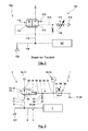
- Fig. 1 1 schematically shows a supply device 102 for a filling system 101 according to the prior art, in which a supply line 106 for a filling device 107 from a pressure source 104 is supplied with pressure. From the supply line 106 branches off a vent line 112, via which fluid can be removed to reduce the pressure at too high pressure in the supply line 106.
- a venting valve 113 arranged in the venting line 112 is in this case acted upon in the direction of a venting position at a first control connection 171 with the unthrottled pressure in the supply line 106.
- the vent valve 113 in the opposite direction, namely in the closing direction, at a second control port 116 of the pressure in a control line 119th is charged.
- the control line 119 is in this case also connected to the supply line 106 with the interposition of a throttle 128.
- the pressure in the control line 119 is limited by a manually adjustable pressure limiting valve 172, via which the control line 119 is connected to a vent 173.
- a manually adjustable pressure limiting valve 172 via which the control line 119 is connected to a vent 173.
- a gradual pressure rise in the supply line 106 beyond a target pressure results in an opening direction force due to the pressure at the first control port 171, which is greater than the force which the pressure in the control line 119 causes at the second control port 116 when the pressure in the control line 119 is reduced by the pressure relief valve 172 against the pressure in the supply line 106 and thus with respect to the pressure at the first control port 171.
- the required pressure difference which must act on the two control terminals 116, 171 to cause a switchover of the venting valve 113, is influenced by a spring 174 acting in the closing direction.
- the invention has for its object to provide a supply device for a bottling plant, which is characterized by low pressure fluctuations in the provision of the flow of the fluid and / or is robust in terms of the effects of any contamination of the fluid. Furthermore, the invention has for its object to propose a correspondingly improved bottling plant.
- a supply device which is intended for a bottling plant for a free-flowing or free-flowing material.
- This pourable or free-flowing material is, for example, solid particles of the same or different size, a dust-like material, a bulk material, a powder or granules, which may also be formed with a plurality of different mixed-part materials.
- the supply device has a supply line. This serves to provide a flow of a fluid, with which the material is transported through the filling plant and to the containers to be filled.
- the supply line may have a pressure source such as a pressure vessel and / or a pump.
- the pressure in such a supply line is not constant. This can be due to pressure fluctuations of the pressure source, in particular the delivery rate of a pump or pressure changes in a container, and / or in a discontinuous decrease behavior of the fluid from the supply line, for example as a result of discontinuous mixing with the material and / or as a result of only temporary Removal of the fluid with the interruption of the decrease in a change from the filling of a container to the filling of another container.
- a venting line is used, which branches off from the supply line.
- a vent valve is arranged in the vent line.
- the venting line is used to influence the pressure in the supply line.
- any increase in pressure in the supply line can be counteracted by opening the venting valve, so that Fluid is discharged from the supply line via the vent line, which then can be counteracted the pressure increase.
- the supply device has a control line, via which the vent valve (and thus the influence of the discharge of fluid through the vent line and thus the influence of the pressure in the supply line) can be controlled.
- a “control” here comprises both a “control” and a “control”.
- the supply line and the control line are fluidly decoupled from each other.
- the supply line on the one hand and the control line on the other hand are not supplied via the same pressure source, but via different pressure sources with pressurized fluid, in particular compressed air. Due to the fluidic decoupling of the supply line on the one hand and the control line on the other hand, undesirable fluidic interactions between the supply line and the control line can be avoided, thus, for example, unstable control or regulation processes can be avoided.
- the vent valve may be formed in any configuration. Thus, this may be formed, for example, in slide design or as a seat valve. It is possible that it is the vent valve is a multi-position valve, with different operating positions of the vent valve can exist in different ventilation cross sections.
- a valve is used as a vent valve, which does not have only discrete switch positions and associated vent cross sections, but which is designed as a proportional valve whose switching positions are continuously variable with a continuous change in the vent cross section.
- the proportional valve can be controlled electrically, pneumatically or electropneumatically. It is also possible here for the proportional valve to have a linear or a non-linear volume flow characteristic.
- the proportional valve is pneumatically controlled by the control line.
- control line is formed closed, which in this only the fluidic admission of a control port of the vent valve takes place and the fluid is reciprocated depending on the control pressure and operating position of any controlling valve body of the vent valve in the control strand.
- control line is connected to a pressure sink, in particular a vent, via a throttle, which can also be understood as an aperture. This has the consequence that the control line is constantly flowed through independently of the operating position of the vent valve (at least in a partial strand between the pressure source and a branch to the pressure sink).
- this has the advantage that any contamination of the fluid in the control line will not be moved back and forth in the control line, where they may affect the operation of the components, in particular the vent valve. Rather, it can be made possible on the constant flow through the control column in consequence of the connection with the pressure sink via the throttle and a discharge of any impurities in the pressure sink or the environment.
- movement of a controlling valve body of the bleed valve causes displacement of the controlling fluid in the control string.
- the fluidic components of the control line and the line cross sections must be suitably dimensioned.
- vent valve is designed without hysteresis.
- a vent valve "without hysteresis” is still understood to mean a vent valve in which an opening pressure of the vent valve and a closing pressure of the vent valve differ by a maximum of 10%, in particular a maximum of 5% or 2%.
- the hysteresis correlates with the ratio of the areas of the valve body that are acted upon by fluid in the closed position and in the open position.
- throttling occurs between the input port and the output port, a more or less large pressure drop between the input port and the output port can be produced, depending on the throttle characteristic.
- the partial area which is added to the fluid in the opening position of the venting valve is exposed to the low pressure at the outlet connection as a result of the throttling action.
- the influence of the action of the fluid on the different partial surfaces of the valve body of the venting valve thus decreases.
- the arrangement of a throttle between the input port and the outlet port of the vent valve is advantageous so that the transfer of the vent valve in the open position does not "abruptly" a change in the force ratios on the vent valve result and abruptly a fluidic flow through the vent valve is brought about, which under certain circumstances, the control and operating behavior of the supply device and / or the bottling plant can be improved.
- the vent valve is designed as a seat valve, can be found in this use any valve body, which comes in the closed position to rest on an associated valve seat.
- the vent valve has a membrane which at least partially forms the valve body. The membrane closes a valve seat in a closed position of the venting valve. The membrane is acted upon in the direction of an open position by the pressure in the supply line, which is supplied to the vent valve via the associated input port. This also includes that the application takes place in the direction of the open position with a pressure which is reduced, for example as a result of throttling on the way to the vent valve, but is dependent on the pressure in the supply line. Finally, the membrane is mechanically coupled to a control piston.
- control piston is acted upon by the pressure in the control line, whereby this the membrane in the direction of the closed position applied. It is quite possible that the membrane is fluidly acted on both sides. But it is also possible that the membrane is acted upon only on one side with the pressure at the inlet port and / or outlet port of the vent valve, while the other side of the membrane is not acted upon fluidically and an admission occurs in the direction of the closed position exclusively via the control piston.
- the throttle may be arranged in an inlet channel and / or outlet channel of the ventilation valve.
- the membrane forms a throttle body or the membrane carries a throttle body.
- the throttle body with the valve seat forms the throttle.
- the throttle effect which is generated between the valve seat and throttle body, be independent of the operating position of the membrane.
- the throttling effect of the operating position of the membrane ie the distance of the membrane from the valve seat, is dependent.
- the throttle body may be cylindrical or tapered or formed with another tapered or widening body (in particular with a curved outer contour), which extends with the operating position dependent extension through the valve seat.
- the influencing of the throttle effect of the operating position can be effected by a change in the throttle cross-section depending on the operating position and / or change in the extent of the throttle longitudinal section through the valve seat depending on the operating position.
- a reservoir is arranged in the control line.
- Such a reservoir basically serves as a kind of "filter” for the pressure prevailing in the control line, since different fluidic volumes in the control line, in particular as a result of an actuating movement of the controlling valve body of the vent valve and / or as a result of irregular delivery of a pump, lower pressure fluctuations result if the volume of the fluid in the control line is greater, so that the provided with the reservoir "additional volume" leads to the reduction of pressure fluctuations.
- the use of a reservoir in the control line is advantageous if the distance between the pressure source of the control line and the vent valve is large or used between the pump and vent valve in the control line leads and / or fluidic components lead to a strong throttling.
- the reservoir is arranged at a small distance to the vent valve.
- the pressure in the control line is kept as constant as possible, whereby the discharge of fluid from the supply line via the vent valve is also constant.
- the pressure in the control line is adjustable, whereby the discharge of fluid from the supply line can be adjusted and thus the flow of fluid through the supply line can be influenced.
- the pressure regulating valve has an electromotive actuator, via which an adjustment of an operating point of the pressure regulating valve can take place.
- the electromotive actuator can be controlled by the user. It is also possible that the electromotive actuator is controlled by evaluating the pressure in the control line and / or venting line and / or supply line.
- the pressure regulating valve is controlled via an electropneumatic pilot control unit.
- the electropneumatic pilot control unit is in this case controlled by a control unit or there is a controlled operation or a controlled operation depending on the pressure signal in the control line, vent line and / or supply line.
- the electropneumatic Pilot control unit may in this case be formed with one or more electropneumatic pilot control valves, wherein the at least one electropneumatic pilot control valve may be designed in any desired type and with any desired operating positions.
- it is an electropneumatic proportional valve, a pulse width modulated valve u. ä.
- the pneumatic supply of the electropneumatic pilot control unit is formed separately from the pressure source of the control line.
- the electropneumatic pilot unit from the pressure source which is here a pneumatic pressure source, the control line is supplied.
- the pressure control valve is directly controlled or regulated electromagnetically.
- the pressure in the control line can be acted upon by the pressure conditions at a control port of the vent valve and thus to the force ratios at the vent valve and the operating position of the vent valve. While it is basically possible that the pressure in the control line acts in the opening direction on the vent valve and / or the pressure in the supply line in the closing direction acts on the vent valve, the vent valve is acted upon in the closing direction of the pressure in the control line for a further proposal of the invention and / or in the opening direction of the pressure in the supply line acted upon. In this case, the pressure in the control line dictates the force which must be generated by the pressure in the supply line to open the vent valve. Thus, the higher the pressure in the control line, the higher the controlled or regulated pressure in the supply line. It is possible in this case that in the closing direction, the force relationships are set to the vent valve exclusively by the pressure in the control line, while alternatively it is possible that additionally acts in the closing direction and a mechanical spring.
- the invention also includes supply devices in which the pressure control valve on the one hand and the vent valve on the other hand are formed separately from each other and are connected to each other via a control line.
- a supply device according to the invention but form the pressure control valve and the vent valve a structural unit, for example, be flanged or screwed to the vent valve, a pressure control valve can.
- the pressure control valve and the vent valve may be arranged in a common housing. It is even possible that the above-explained throttle, via which the constant flow of the control line is ensured, is also integrated into the unit.
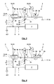
- Fig. 2 shows a filling plant 1 with a supply device 2.
- the supply device 2 has a supply line 3.
- a fluid under pressure in particular compressed air
- the pressure source 4 is via a Supply line 6 connected to a filling device 7 of the filling system 1.
- a preparation of the mixture of the fluid and the material and the metered delivery of the material with the fluid to a container which also possible is that in the filling device 7 is a branch to a plurality of parallel filling strands, via which the filling of containers takes place in parallel with the material.
- an intermittent discharge of material through the filling device 7, which is preferably interrupted by a kind of valve or dispensing device, the delivery of material can be.
- the filling device 7 should preferably be supplied with fluid at a constant pressure, independently of the operating state of the filling device 7.
- a vent valve 13 is arranged, which has at least one open position, preferably a plurality of open positions with different opening cross-sections, and a closed position.
- the vent valve 13 is formed as a proportional valve 14, which has different (preferably continuously variable) vent cross sections depending on the operating position.
- the vent valve 13 is acted upon via a first control port 71 with the pressure in the vent line 12 (and thus the pressure in the supply line 6) in the opening direction.
- the vent valve 13 has an input port 48 connected to the power cord 3 and an output port 49 connected to the pressure sink 10.
- the fluid control of a second control connection 16 of the venting valve 13 takes place via a control line 15.
- the pressure at the second control connection 16 acts counter to the pressure at the first control connection 71, namely in the closing direction.
- the control line 15 has a pressure source 17, preferably a pump 18, via which the control line 15 is supplied with a pressurized fluid, in particular compressed air ,
- the pressure source 17 of the control line 15 is formed separately from the pressure source 4 of the supply line 3.
- the control line 15 is fluidly separated from the supply line 3 (which in this case is quite possible that the two vents 11, 26 are structurally combined).
- a pressure control valve 20 is arranged, which predetermines the pressure at the control port 16, in particular by this the funded by the pressure source 4 compressed air with exceeding a threshold value of the pressure of a vent 75 feeds. Furthermore, via a branch 21, a display device 22, which may also be a sensor 23 with display connected thereto, is connected, via which a detection and display of a pressure in the control line 19 is possible.
- the control line 19 is connected to a leading to a pressure sink 25 or vent 26 flow line 27.
- a throttle 28 preferably a diaphragm arranged.
- the pressure control valve 20 is adjustable via an adjusting device 29, wherein the adjusting device 29 by an operator manually, for example via a thumbwheel, can be operated or according to Fig. 4 can be actuated via an electromotive actuator 30.
- an electromotive actuator 30 the actuation of the actuator 30 can in turn be done manually by the operator, in particular by operating a switch or a continuously variable actuator, or it can be a control or regulation of the actuation of the actuator 30 by an electronic control unit.
- the operation of the filling plant 1 is preferably carried out as follows:
- the pressure source 4 By means of the pressure source 4, the provision of fluid under pressure to the filling device 7, with which continuously or discontinuously fluid is removed from the supply line 3 takes place.
- the fluid provided by the pressure source 4 divides on the one hand into the fluid withdrawn from the filling device 7 and on the other hand any, depending on the opening position of the vent valve 13 via the vent line 9 discharged fluid.
- the influencing can be controlled via the fluidic admission of the control connection 16 via the control line 15.
- the actuation of the adjustment device 29 can ultimately influence how much fluid is supplied from the supply line 3 to the filling device 7.
- the actuation of the adjusting device 29 is coordinated with the operation of the filling device 7.
- an actuation of the adjusting device 29 is carried out such that the Venting valve 13 is transferred to a (further) opening position, so that instead of the decrease of fluid through the filling device 7, a discharge of the fluid via the venting line 9 can take place.
- the venting valve 13 with the control connection 71 is preferably a pressure limiting valve or pressure regulating valve whose limiting or regulating pressure can be influenced or predetermined via the pressure at the second control connection 16.
- the throttle 28 has a fixed throttle characteristic
- the throttle characteristic via an adjustment 31 changeable the actuation of the adjustment device 31 can be carried out manually by the operator or automatically by a control device, wherein an actuation of the adjustment 31 can be done manually or automatically and independently or in a coordinated manner with the operation of the adjustment 29 and / or the operating state of the filling device 7 ,
- control line 19 is connected to the control line 19 via a branch 32, a reservoir 33, via which a complementary influence, in particular a constant and a damping of oscillations, the pressure conditions in the control line 15 is possible.
- the pressure control valve 20 fluidly controlled via a control port 34.
- the pilot unit 35 is formed with two 2/2-way solenoid valves 36, 37, each having a blocking position and a passage position.
- the 2/2-way solenoid valve 36 connects in its passage position the control port 34 with a pressure sink 38 or vent 39, while the 2/2-way solenoid valve in its passage position the control port 34 to the control line, here the pressure source 17 or pump 18th , connects.
- the 2/2-way solenoid valves 36, 37 have electrical control terminals 40, 41. These are driven to bring about the different valve positions mentioned via an electronic control unit 42.
- the control unit 42 converts a predetermined by the operator via a switch or a controller signal. It is also possible that the control unit activates the pilot control unit 35 for regulating a setpoint pressure in the control line 15.
- the control unit 42 can be supplied with a pressure signal which is detected by the sensor 23 in the control line 15.
- control unit 42 carries out an automatic control such that desired fluidic conditions in the supply line 3, in particular desired pressure profiles and / or volume flows in the supply line 3, are ensured.
- control unit 42 to control the control of the pilot control unit 35 in response to a detected in the supply line 3 pressure signal and / or in response to an operating state of the filling device 7.
- the pressure control valve 20 was purely pneumatically controlled. In particular, here was no electrical control of the pressure control valve 20 itself available. The control of the operating position of the pressure control valve 20 was carried out here by the return of the pressure in the control line 19 and the control port 16 via the dashed line, so that the operating position of the pressure control valve of the pressure at the control port 16 was dependent and this pressure on a valve surface of Pressure control valve 20 has acted.
- Fig. 6 illustrated embodiment in otherwise substantially Fig.
- a pressure control valve 43 insert whose operating position is not directly dependent on the acting pneumatic pressures, so that here no pneumatic pressure, in particular not the pressure at the control port 16, acts on a valve body of the pressure control valve 43.
- the pressure control valve 43 is designed as a solenoid valve 44, which is electrically controlled by the control unit 42 via an electrical control connection 45.
- the solenoid valve 44 is designed as a pulse width modulated valve, so that even in the event that the solenoid valve 44 has only one open and one closed position, depending on the pulse width modulation different pressures on the control terminal 16 of the vent valve 13 can be brought about.
- the solenoid valve 44 is formed as an electromagnetically controlled proportional valve 46, in which, depending on the energization of the control terminal 45, a continuously changing opening cross-section of the pressure control valve 43 results.
- the control of the operating position of the pressure control valve 43 on the one hand in response to the pressure signal of the sensor 23.
- the control of the solenoid valve 44 by the control unit 42 in response to the specification of an operator and / or in dependence on other operating variables, in particular the filling device 7, take place.
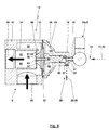
- the vent valve 13 is shown in greater constructive detail.
- This has a valve housing 47, which has an input port 48 and an output port 49.
- the input port 48 and the output port 49 open into an interior 50, in which in the closed position of the vent valve 13 according to Fig. 7 a diaphragm 51 closes a valve seat 52, whereby a passage between the input port 48 and the output port 49 is shut off.
- the input terminal 48 is connected via the branch 8 to the supply line 6, while the output terminal 49 is connected to the pressure sink 10 or vent 11.
- the output port 49 continues into the interior of the valve housing 47 with an outlet channel 53, which is bounded radially outwardly by a sleeve-like extension 54 whose end region facing away from the outlet port 49, the valve seat 52nd formed.
- an annular input chamber 55 is formed by the valve housing 47, in which the input port 48 opens.
- the interior 50 of the valve housing 47 is closed by a housing cover 56. In the annular or flange-like connection region between the housing cover 56 and the valve housing 47, the membrane 41 is fixed or clamped.
- the diaphragm 51 On the side facing the valve seat 52, the diaphragm 51 carries a throttle body 57, which has a lateral surface 58, which tapers in the direction of the interior of the valve seat 52.
- the lateral surface 58 of the throttle body 57 is conical, resulting in the illustrated longitudinal section, a trapezoidal outer geometry of the throttle body 57.
- a control piston 59 is attached to this. In the end region facing away from the diaphragm 51, the control piston 59 is displaceably guided under sealing by a sealing element 60 in a control bore 61 of the housing cover 56.
- the housing cover 56 bounded in the region of the control bore 61 together with the diaphragm 51 facing away from the end face of the control piston 59 a control chamber 62 whose volume of the operating position of the control piston 59 (and thus the diaphragm 51 and the vent valve 13) is dependent.
- a rear space 64 of the diaphragm 51, which is arranged on the input chamber 55 and the output channel 53 facing away from the side of the membrane 51 is vented through vent holes 65 of the housing cover 56.
- control chamber 62 opens the end face of the control port 16 through which the vent valve 13 is acted upon by the control pressure in the control line 15.
- the flow line 27 is also formed by the housing cover 56 with arranged therein throttle 28 or aperture.
- the pressure pv of the supply line 3 is applied via the inlet connection 48 in the inlet chamber 55.
- This pressure acts on the annular surface A R of the diaphragm 51, which extends radially between the valve seat 52 and the outer boundary of the input chamber 55.
- the control force Fs outweighs and the diaphragm 51 is sealingly pressed against the sealing seat 52 with the resulting differential force Fö - Fs. Otherwise, the opening force Fö outweighs, so that the diaphragm 51 from the closed position according to Fig. 7 in the open position according to Fig. 8 is transferred.
- the opening force Fö outweighs, so that the diaphragm 51 from the closed position according to Fig. 7 in the open position according to Fig. 8 is transferred.
- the opening behavior of the venting valve 13 can be changed, in particular the pressure pv, for which the venting valve 13 leaves its closed position.
- the membrane 15 forms a valve body 66 together with the throttle body 57. In the open position of the vent valve 13 according to Fig.
- the opening cross-section 67 connects in the open position, the input port 48 to the output port 49.
- the opening cross-section 67 here forms a throttle 68. This results in the throttle 68 through the narrow throttling annular channel, which is bounded radially outwardly from the extension 54 and the valve seat 52 and radially inwardly of the lateral surface 58 of the throttle body 57 and the diaphragm 51 is limited.
- the vent valve 13 preferably has a sufficiently small or no hysteresis.
- the pressure control valve 20, 43 is connected via a control line 19 at the control terminal 16.
- a control line 19 at the control terminal 16.
- the pressure control valve 20, 43 with a connecting piece 70 which has an external thread, screwed into a corresponding internal thread of the control terminal 16.
- the fluid on the one hand in the supply line 3 and the venting line 9 and on the other hand in the control line 15 may be the same or different arbitrary fluids.
- these are pneumatic strands 3, 9, 15.
- the illustrated components can all be arranged in such an explosion-proof room, while this for the embodiments according to 4 to 6 for all components except for the actuator 30, the control unit 42 and the electropneumatic valve unit 35 and the solenoid valve 43 is the case.
- a control unit 42 can also take into account when controlling the pressure control valve 20 or the pilot control unit 35, if a switchover from a first number of filling branches, which are supplied via the supply line 3, to a second number of filling branches.
Landscapes
- Engineering & Computer Science (AREA)
- General Engineering & Computer Science (AREA)
- Mechanical Engineering (AREA)
- Filling Or Discharging Of Gas Storage Vessels (AREA)
- Basic Packing Technique (AREA)
Priority Applications (1)
| Application Number | Priority Date | Filing Date | Title |
|---|---|---|---|
| EP15179866.7A EP3127841A1 (fr) | 2015-08-05 | 2015-08-05 | Dispositif de conditionnement et dispositif d'alimentation pour dispositif de conditionnement |
Applications Claiming Priority (1)
| Application Number | Priority Date | Filing Date | Title |
|---|---|---|---|
| EP15179866.7A EP3127841A1 (fr) | 2015-08-05 | 2015-08-05 | Dispositif de conditionnement et dispositif d'alimentation pour dispositif de conditionnement |
Publications (2)
| Publication Number | Publication Date |
|---|---|
| EP3127841A1 true EP3127841A1 (fr) | 2017-02-08 |
| EP3127841A8 EP3127841A8 (fr) | 2017-03-29 |
Family
ID=53835918
Family Applications (1)
| Application Number | Title | Priority Date | Filing Date |
|---|---|---|---|
| EP15179866.7A Withdrawn EP3127841A1 (fr) | 2015-08-05 | 2015-08-05 | Dispositif de conditionnement et dispositif d'alimentation pour dispositif de conditionnement |
Country Status (1)
| Country | Link |
|---|---|
| EP (1) | EP3127841A1 (fr) |
Cited By (1)
| Publication number | Priority date | Publication date | Assignee | Title |
|---|---|---|---|---|
| EP3647606A1 (fr) * | 2018-10-29 | 2020-05-06 | WS Wieländer + Schill Professionelle Karosserie- Spezialwerkzeuge GmbH & Co. KG | Système doté d'un outil hydraulique à fonctionnement pneumatique, robinet d'arrêt ainsi que chariot pour un outil hydraulique à fonctionnement pneumatique |
Citations (7)
| Publication number | Priority date | Publication date | Assignee | Title |
|---|---|---|---|---|
| GB439819A (en) * | 1934-06-15 | 1935-12-16 | Nikolai Ahlmann | Improvements in or relating to methods of and apparatus for rendering powdered materials fluid |
| US2667860A (en) * | 1952-04-26 | 1954-02-02 | Mcalear Mfg Company | Pressure responsive valve positioner |
| DE1802417A1 (de) * | 1967-10-16 | 1969-06-12 | H J Heinz Company Ltd | Vorrichtung zur Befoerderung fliessfaehigen Materials |
| JPS62283276A (ja) * | 1986-05-30 | 1987-12-09 | Kubota Ltd | バルブの流量調節方法 |
| JP2004076787A (ja) * | 2002-08-12 | 2004-03-11 | Advance Denki Kogyo Kk | ダイヤフラム弁構造 |
| US20050089378A1 (en) * | 2003-10-23 | 2005-04-28 | Gerber Milton L. | Apparatus and method for conveying and vacuuming fibrous insulation material |
| EP1553339A1 (fr) * | 2004-01-06 | 2005-07-13 | Toflo Corporation | Soupape de contrôle de débit et dispositif de contrôle de débit |
-
2015
- 2015-08-05 EP EP15179866.7A patent/EP3127841A1/fr not_active Withdrawn
Patent Citations (7)
| Publication number | Priority date | Publication date | Assignee | Title |
|---|---|---|---|---|
| GB439819A (en) * | 1934-06-15 | 1935-12-16 | Nikolai Ahlmann | Improvements in or relating to methods of and apparatus for rendering powdered materials fluid |
| US2667860A (en) * | 1952-04-26 | 1954-02-02 | Mcalear Mfg Company | Pressure responsive valve positioner |
| DE1802417A1 (de) * | 1967-10-16 | 1969-06-12 | H J Heinz Company Ltd | Vorrichtung zur Befoerderung fliessfaehigen Materials |
| JPS62283276A (ja) * | 1986-05-30 | 1987-12-09 | Kubota Ltd | バルブの流量調節方法 |
| JP2004076787A (ja) * | 2002-08-12 | 2004-03-11 | Advance Denki Kogyo Kk | ダイヤフラム弁構造 |
| US20050089378A1 (en) * | 2003-10-23 | 2005-04-28 | Gerber Milton L. | Apparatus and method for conveying and vacuuming fibrous insulation material |
| EP1553339A1 (fr) * | 2004-01-06 | 2005-07-13 | Toflo Corporation | Soupape de contrôle de débit et dispositif de contrôle de débit |
Cited By (1)
| Publication number | Priority date | Publication date | Assignee | Title |
|---|---|---|---|---|
| EP3647606A1 (fr) * | 2018-10-29 | 2020-05-06 | WS Wieländer + Schill Professionelle Karosserie- Spezialwerkzeuge GmbH & Co. KG | Système doté d'un outil hydraulique à fonctionnement pneumatique, robinet d'arrêt ainsi que chariot pour un outil hydraulique à fonctionnement pneumatique |
Also Published As
| Publication number | Publication date |
|---|---|
| EP3127841A8 (fr) | 2017-03-29 |
Similar Documents
| Publication | Publication Date | Title |
|---|---|---|
| DE112011102092B4 (de) | Druckreduziervorrichtung | |
| DE4243577B4 (de) | Mit Druckmittel arbeitende Niveauregeleinrichtung | |
| EP1629225A1 (fr) | Vanne d'arret reagissant a la pression et systeme hydraulique comprenant une vanne d'arret de ce type | |
| EP1299649B1 (fr) | Dispositif pour creer le vide | |
| DE3305092C2 (fr) | ||
| DE2748079A1 (de) | Wasserdruck-verstaerkungssystem und steuerventil sowie steuerverfahren | |
| WO2013152817A1 (fr) | Unité de traitement d'air pour l'alimentation en air comprimé de véhicules utilitaires | |
| EP2866115B1 (fr) | Vanne dotée d'une cartouche échangeable | |
| DE102007050151B4 (de) | Druckentlastetes Schaltventil und Federanlage | |
| DE10322585B4 (de) | Ventilbaukastensysteme | |
| CH708877B1 (de) | Hydraulikventilanordnung mit Steuerungs-/Regelungsfunktion und zugehöriges Rücklaufventil. | |
| CH670483A5 (fr) | ||
| DE4108915A1 (de) | Hydraulische einrichtung zur druckmittelversorgung eines bevorrechtigten primaerlastkreises | |
| EP3127841A1 (fr) | Dispositif de conditionnement et dispositif d'alimentation pour dispositif de conditionnement | |
| CH708876B1 (de) | Hydraulikventilanordnung mit Steuerungs-/Regelungsfunktion und zugehöriges Rücklaufventil. | |
| EP2307777B1 (fr) | Valve | |
| EP2719903A2 (fr) | Agencement de vannes | |
| DE2932523C2 (de) | Hydraulisch entsperrbares Sitzventil | |
| DE19711739C1 (de) | Governor für Druckluftbeschaffungsanlagen von Fahrzeugen | |
| DE2205508C2 (de) | Hydraulische Steuereinrichtung | |
| DE4445146A1 (de) | Schutzsystem für eine Druckmittelanlage | |
| EP2789512B1 (fr) | Dispositif de préparation d'air comprimé pour un véhicule utilitaire | |
| EP0758063A1 (fr) | Soupape de mise en marche pour systèmes pneumatiques | |
| DE102004023553B3 (de) | Hydraulik-Ventilanordnung, insbesondere Wasserhydraulik-Ventilanordnung | |
| DE1949761A1 (de) | Luftfederung fuer Fahrzeuge |
Legal Events
| Date | Code | Title | Description |
|---|---|---|---|
| PUAI | Public reference made under article 153(3) epc to a published international application that has entered the european phase |
Free format text: ORIGINAL CODE: 0009012 |
|
| AK | Designated contracting states |
Kind code of ref document: A1 Designated state(s): AL AT BE BG CH CY CZ DE DK EE ES FI FR GB GR HR HU IE IS IT LI LT LU LV MC MK MT NL NO PL PT RO RS SE SI SK SM TR |
|
| AX | Request for extension of the european patent |
Extension state: BA ME |
|
| RAP1 | Party data changed (applicant data changed or rights of an application transferred) |
Owner name: SCHULTE, REINHOLD Owner name: IWN GMBH & CO. KG |
|
| 17P | Request for examination filed |
Effective date: 20170511 |
|
| RBV | Designated contracting states (corrected) |
Designated state(s): AL AT BE BG CH CY CZ DE DK EE ES FI FR GB GR HR HU IE IS IT LI LT LU LV MC MK MT NL NO PL PT RO RS SE SI SK SM TR |
|
| 17Q | First examination report despatched |
Effective date: 20170907 |
|
| STAA | Information on the status of an ep patent application or granted ep patent |
Free format text: STATUS: THE APPLICATION IS DEEMED TO BE WITHDRAWN |
|
| 18D | Application deemed to be withdrawn |
Effective date: 20190316 |