EP3127683B1 - Schweissstation zum verschweissen von folienbeuteln und verfahren dazu - Google Patents
Schweissstation zum verschweissen von folienbeuteln und verfahren dazu Download PDFInfo
- Publication number
- EP3127683B1 EP3127683B1 EP15180151.1A EP15180151A EP3127683B1 EP 3127683 B1 EP3127683 B1 EP 3127683B1 EP 15180151 A EP15180151 A EP 15180151A EP 3127683 B1 EP3127683 B1 EP 3127683B1
- Authority
- EP
- European Patent Office
- Prior art keywords
- sealing
- welding
- arms
- film bags
- drive shaft
- Prior art date
- Legal status (The legal status is an assumption and is not a legal conclusion. Google has not performed a legal analysis and makes no representation as to the accuracy of the status listed.)
- Active
Links
Images

Classifications
-
- B—PERFORMING OPERATIONS; TRANSPORTING
- B65—CONVEYING; PACKING; STORING; HANDLING THIN OR FILAMENTARY MATERIAL
- B65B—MACHINES, APPARATUS OR DEVICES FOR, OR METHODS OF, PACKAGING ARTICLES OR MATERIALS; UNPACKING
- B65B51/00—Devices for, or methods of, sealing or securing package folds or closures; Devices for gathering or twisting wrappers, or necks of bags
- B65B51/10—Applying or generating heat or pressure or combinations thereof
- B65B51/22—Applying or generating heat or pressure or combinations thereof by friction or ultrasonic or high-frequency electrical means, i.e. by friction or ultrasonic or induction welding
- B65B51/225—Applying or generating heat or pressure or combinations thereof by friction or ultrasonic or high-frequency electrical means, i.e. by friction or ultrasonic or induction welding by ultrasonic welding
-
- B—PERFORMING OPERATIONS; TRANSPORTING
- B29—WORKING OF PLASTICS; WORKING OF SUBSTANCES IN A PLASTIC STATE IN GENERAL
- B29C—SHAPING OR JOINING OF PLASTICS; SHAPING OF MATERIAL IN A PLASTIC STATE, NOT OTHERWISE PROVIDED FOR; AFTER-TREATMENT OF THE SHAPED PRODUCTS, e.g. REPAIRING
- B29C65/00—Joining or sealing of preformed parts, e.g. welding of plastics materials; Apparatus therefor
- B29C65/02—Joining or sealing of preformed parts, e.g. welding of plastics materials; Apparatus therefor by heating, with or without pressure
- B29C65/08—Joining or sealing of preformed parts, e.g. welding of plastics materials; Apparatus therefor by heating, with or without pressure using ultrasonic vibrations
-
- B—PERFORMING OPERATIONS; TRANSPORTING
- B29—WORKING OF PLASTICS; WORKING OF SUBSTANCES IN A PLASTIC STATE IN GENERAL
- B29C—SHAPING OR JOINING OF PLASTICS; SHAPING OF MATERIAL IN A PLASTIC STATE, NOT OTHERWISE PROVIDED FOR; AFTER-TREATMENT OF THE SHAPED PRODUCTS, e.g. REPAIRING
- B29C66/00—General aspects of processes or apparatus for joining preformed parts
- B29C66/01—General aspects dealing with the joint area or with the area to be joined
- B29C66/05—Particular design of joint configurations
- B29C66/10—Particular design of joint configurations particular design of the joint cross-sections
- B29C66/11—Joint cross-sections comprising a single joint-segment, i.e. one of the parts to be joined comprising a single joint-segment in the joint cross-section
- B29C66/112—Single lapped joints
- B29C66/1122—Single lap to lap joints, i.e. overlap joints
-
- B—PERFORMING OPERATIONS; TRANSPORTING
- B29—WORKING OF PLASTICS; WORKING OF SUBSTANCES IN A PLASTIC STATE IN GENERAL
- B29C—SHAPING OR JOINING OF PLASTICS; SHAPING OF MATERIAL IN A PLASTIC STATE, NOT OTHERWISE PROVIDED FOR; AFTER-TREATMENT OF THE SHAPED PRODUCTS, e.g. REPAIRING
- B29C66/00—General aspects of processes or apparatus for joining preformed parts
- B29C66/40—General aspects of joining substantially flat articles, e.g. plates, sheets or web-like materials; Making flat seams in tubular or hollow articles; Joining single elements to substantially flat surfaces
- B29C66/41—Joining substantially flat articles ; Making flat seams in tubular or hollow articles
- B29C66/43—Joining a relatively small portion of the surface of said articles
- B29C66/431—Joining the articles to themselves
- B29C66/4312—Joining the articles to themselves for making flat seams in tubular or hollow articles, e.g. transversal seams
- B29C66/43121—Closing the ends of tubular or hollow single articles, e.g. closing the ends of bags
-
- B—PERFORMING OPERATIONS; TRANSPORTING
- B29—WORKING OF PLASTICS; WORKING OF SUBSTANCES IN A PLASTIC STATE IN GENERAL
- B29C—SHAPING OR JOINING OF PLASTICS; SHAPING OF MATERIAL IN A PLASTIC STATE, NOT OTHERWISE PROVIDED FOR; AFTER-TREATMENT OF THE SHAPED PRODUCTS, e.g. REPAIRING
- B29C66/00—General aspects of processes or apparatus for joining preformed parts
- B29C66/80—General aspects of machine operations or constructions and parts thereof
- B29C66/81—General aspects of the pressing elements, i.e. the elements applying pressure on the parts to be joined in the area to be joined, e.g. the welding jaws or clamps
- B29C66/814—General aspects of the pressing elements, i.e. the elements applying pressure on the parts to be joined in the area to be joined, e.g. the welding jaws or clamps characterised by the design of the pressing elements, e.g. of the welding jaws or clamps
- B29C66/8145—General aspects of the pressing elements, i.e. the elements applying pressure on the parts to be joined in the area to be joined, e.g. the welding jaws or clamps characterised by the design of the pressing elements, e.g. of the welding jaws or clamps characterised by the constructional aspects of the pressing elements, e.g. of the welding jaws or clamps
- B29C66/81463—General aspects of the pressing elements, i.e. the elements applying pressure on the parts to be joined in the area to be joined, e.g. the welding jaws or clamps characterised by the design of the pressing elements, e.g. of the welding jaws or clamps characterised by the constructional aspects of the pressing elements, e.g. of the welding jaws or clamps comprising a plurality of single pressing elements, e.g. a plurality of sonotrodes, or comprising a plurality of single counter-pressing elements, e.g. a plurality of anvils, said plurality of said single elements being suitable for making a single joint
- B29C66/81469—General aspects of the pressing elements, i.e. the elements applying pressure on the parts to be joined in the area to be joined, e.g. the welding jaws or clamps characterised by the design of the pressing elements, e.g. of the welding jaws or clamps characterised by the constructional aspects of the pressing elements, e.g. of the welding jaws or clamps comprising a plurality of single pressing elements, e.g. a plurality of sonotrodes, or comprising a plurality of single counter-pressing elements, e.g. a plurality of anvils, said plurality of said single elements being suitable for making a single joint one placed next to the other in a single line transverse to the feed direction, e.g. shoulder to shoulder sonotrodes
-
- B—PERFORMING OPERATIONS; TRANSPORTING
- B29—WORKING OF PLASTICS; WORKING OF SUBSTANCES IN A PLASTIC STATE IN GENERAL
- B29C—SHAPING OR JOINING OF PLASTICS; SHAPING OF MATERIAL IN A PLASTIC STATE, NOT OTHERWISE PROVIDED FOR; AFTER-TREATMENT OF THE SHAPED PRODUCTS, e.g. REPAIRING
- B29C66/00—General aspects of processes or apparatus for joining preformed parts
- B29C66/80—General aspects of machine operations or constructions and parts thereof
- B29C66/82—Pressure application arrangements, e.g. transmission or actuating mechanisms for joining tools or clamps
- B29C66/822—Transmission mechanisms
- B29C66/8221—Scissor or lever mechanisms, i.e. involving a pivot point
-
- B—PERFORMING OPERATIONS; TRANSPORTING
- B29—WORKING OF PLASTICS; WORKING OF SUBSTANCES IN A PLASTIC STATE IN GENERAL
- B29C—SHAPING OR JOINING OF PLASTICS; SHAPING OF MATERIAL IN A PLASTIC STATE, NOT OTHERWISE PROVIDED FOR; AFTER-TREATMENT OF THE SHAPED PRODUCTS, e.g. REPAIRING
- B29C66/00—General aspects of processes or apparatus for joining preformed parts
- B29C66/80—General aspects of machine operations or constructions and parts thereof
- B29C66/82—Pressure application arrangements, e.g. transmission or actuating mechanisms for joining tools or clamps
- B29C66/822—Transmission mechanisms
- B29C66/8222—Pinion or rack mechanisms
-
- B—PERFORMING OPERATIONS; TRANSPORTING
- B29—WORKING OF PLASTICS; WORKING OF SUBSTANCES IN A PLASTIC STATE IN GENERAL
- B29C—SHAPING OR JOINING OF PLASTICS; SHAPING OF MATERIAL IN A PLASTIC STATE, NOT OTHERWISE PROVIDED FOR; AFTER-TREATMENT OF THE SHAPED PRODUCTS, e.g. REPAIRING
- B29C66/00—General aspects of processes or apparatus for joining preformed parts
- B29C66/80—General aspects of machine operations or constructions and parts thereof
- B29C66/82—Pressure application arrangements, e.g. transmission or actuating mechanisms for joining tools or clamps
- B29C66/824—Actuating mechanisms
- B29C66/8246—Servomechanisms, e.g. servomotors
-
- B—PERFORMING OPERATIONS; TRANSPORTING
- B29—WORKING OF PLASTICS; WORKING OF SUBSTANCES IN A PLASTIC STATE IN GENERAL
- B29C—SHAPING OR JOINING OF PLASTICS; SHAPING OF MATERIAL IN A PLASTIC STATE, NOT OTHERWISE PROVIDED FOR; AFTER-TREATMENT OF THE SHAPED PRODUCTS, e.g. REPAIRING
- B29C66/00—General aspects of processes or apparatus for joining preformed parts
- B29C66/80—General aspects of machine operations or constructions and parts thereof
- B29C66/83—General aspects of machine operations or constructions and parts thereof characterised by the movement of the joining or pressing tools
- B29C66/832—Reciprocating joining or pressing tools
- B29C66/8324—Joining or pressing tools pivoting around one axis
- B29C66/83241—Joining or pressing tools pivoting around one axis cooperating pivoting tools
-
- B—PERFORMING OPERATIONS; TRANSPORTING
- B29—WORKING OF PLASTICS; WORKING OF SUBSTANCES IN A PLASTIC STATE IN GENERAL
- B29C—SHAPING OR JOINING OF PLASTICS; SHAPING OF MATERIAL IN A PLASTIC STATE, NOT OTHERWISE PROVIDED FOR; AFTER-TREATMENT OF THE SHAPED PRODUCTS, e.g. REPAIRING
- B29C66/00—General aspects of processes or apparatus for joining preformed parts
- B29C66/80—General aspects of machine operations or constructions and parts thereof
- B29C66/84—Specific machine types or machines suitable for specific applications
- B29C66/843—Machines for making separate joints at the same time in different planes; Machines for making separate joints at the same time mounted in parallel or in series
- B29C66/8432—Machines for making separate joints at the same time mounted in parallel or in series
-
- B—PERFORMING OPERATIONS; TRANSPORTING
- B29—WORKING OF PLASTICS; WORKING OF SUBSTANCES IN A PLASTIC STATE IN GENERAL
- B29C—SHAPING OR JOINING OF PLASTICS; SHAPING OF MATERIAL IN A PLASTIC STATE, NOT OTHERWISE PROVIDED FOR; AFTER-TREATMENT OF THE SHAPED PRODUCTS, e.g. REPAIRING
- B29C66/00—General aspects of processes or apparatus for joining preformed parts
- B29C66/80—General aspects of machine operations or constructions and parts thereof
- B29C66/84—Specific machine types or machines suitable for specific applications
- B29C66/849—Packaging machines
-
- B—PERFORMING OPERATIONS; TRANSPORTING
- B29—WORKING OF PLASTICS; WORKING OF SUBSTANCES IN A PLASTIC STATE IN GENERAL
- B29C—SHAPING OR JOINING OF PLASTICS; SHAPING OF MATERIAL IN A PLASTIC STATE, NOT OTHERWISE PROVIDED FOR; AFTER-TREATMENT OF THE SHAPED PRODUCTS, e.g. REPAIRING
- B29C66/00—General aspects of processes or apparatus for joining preformed parts
- B29C66/90—Measuring or controlling the joining process
- B29C66/92—Measuring or controlling the joining process by measuring or controlling the pressure, the force, the mechanical power or the displacement of the joining tools
- B29C66/924—Measuring or controlling the joining process by measuring or controlling the pressure, the force, the mechanical power or the displacement of the joining tools by controlling or regulating the pressure, the force, the mechanical power or the displacement of the joining tools
- B29C66/9261—Measuring or controlling the joining process by measuring or controlling the pressure, the force, the mechanical power or the displacement of the joining tools by controlling or regulating the pressure, the force, the mechanical power or the displacement of the joining tools by controlling or regulating the displacement of the joining tools
- B29C66/92611—Measuring or controlling the joining process by measuring or controlling the pressure, the force, the mechanical power or the displacement of the joining tools by controlling or regulating the pressure, the force, the mechanical power or the displacement of the joining tools by controlling or regulating the displacement of the joining tools by controlling or regulating the gap between the joining tools
- B29C66/92615—Measuring or controlling the joining process by measuring or controlling the pressure, the force, the mechanical power or the displacement of the joining tools by controlling or regulating the pressure, the force, the mechanical power or the displacement of the joining tools by controlling or regulating the displacement of the joining tools by controlling or regulating the gap between the joining tools the gap being non-constant over time
-
- B—PERFORMING OPERATIONS; TRANSPORTING
- B29—WORKING OF PLASTICS; WORKING OF SUBSTANCES IN A PLASTIC STATE IN GENERAL
- B29C—SHAPING OR JOINING OF PLASTICS; SHAPING OF MATERIAL IN A PLASTIC STATE, NOT OTHERWISE PROVIDED FOR; AFTER-TREATMENT OF THE SHAPED PRODUCTS, e.g. REPAIRING
- B29C66/00—General aspects of processes or apparatus for joining preformed parts
- B29C66/90—Measuring or controlling the joining process
- B29C66/92—Measuring or controlling the joining process by measuring or controlling the pressure, the force, the mechanical power or the displacement of the joining tools
- B29C66/929—Measuring or controlling the joining process by measuring or controlling the pressure, the force, the mechanical power or the displacement of the joining tools characterized by specific pressure, force, mechanical power or displacement values or ranges
- B29C66/9292—Measuring or controlling the joining process by measuring or controlling the pressure, the force, the mechanical power or the displacement of the joining tools characterized by specific pressure, force, mechanical power or displacement values or ranges in explicit relation to another variable, e.g. pressure diagrams
- B29C66/92921—Measuring or controlling the joining process by measuring or controlling the pressure, the force, the mechanical power or the displacement of the joining tools characterized by specific pressure, force, mechanical power or displacement values or ranges in explicit relation to another variable, e.g. pressure diagrams in specific relation to time, e.g. pressure-time diagrams
-
- B—PERFORMING OPERATIONS; TRANSPORTING
- B65—CONVEYING; PACKING; STORING; HANDLING THIN OR FILAMENTARY MATERIAL
- B65B—MACHINES, APPARATUS OR DEVICES FOR, OR METHODS OF, PACKAGING ARTICLES OR MATERIALS; UNPACKING
- B65B51/00—Devices for, or methods of, sealing or securing package folds or closures; Devices for gathering or twisting wrappers, or necks of bags
- B65B51/10—Applying or generating heat or pressure or combinations thereof
- B65B51/14—Applying or generating heat or pressure or combinations thereof by reciprocating or oscillating members
- B65B51/146—Closing bags
-
- B—PERFORMING OPERATIONS; TRANSPORTING
- B65—CONVEYING; PACKING; STORING; HANDLING THIN OR FILAMENTARY MATERIAL
- B65B—MACHINES, APPARATUS OR DEVICES FOR, OR METHODS OF, PACKAGING ARTICLES OR MATERIALS; UNPACKING
- B65B65/00—Details peculiar to packaging machines and not otherwise provided for; Arrangements of such details
- B65B65/02—Driving gear
-
- B—PERFORMING OPERATIONS; TRANSPORTING
- B29—WORKING OF PLASTICS; WORKING OF SUBSTANCES IN A PLASTIC STATE IN GENERAL
- B29L—INDEXING SCHEME ASSOCIATED WITH SUBCLASS B29C, RELATING TO PARTICULAR ARTICLES
- B29L2031/00—Other particular articles
- B29L2031/712—Containers; Packaging elements or accessories, Packages
- B29L2031/7128—Bags, sacks, sachets
-
- B—PERFORMING OPERATIONS; TRANSPORTING
- B65—CONVEYING; PACKING; STORING; HANDLING THIN OR FILAMENTARY MATERIAL
- B65B—MACHINES, APPARATUS OR DEVICES FOR, OR METHODS OF, PACKAGING ARTICLES OR MATERIALS; UNPACKING
- B65B9/00—Enclosing successive articles, or quantities of material, e.g. liquids or semiliquids, in flat, folded, or tubular webs of flexible sheet material; Subdividing filled flexible tubes to form packages
Definitions
- the invention relates to a welding station for welding foil bags according to the preamble of claim 1 and a corresponding method according to claim 7.
- Foil bag welding devices for welding filled foil bags which comprise a holding device and a welding station.
- the welding station In order to bring the welding station for a welding process into the upper region of the foil bags arranged below it by means of the holding device, the welding station is moved relative to the holding device by means of a linkage with a toggle lever and a compressed air spring.
- the contact pressure of the welding station on the halves of the film bag to be welded also results from the linkage with toggle lever and compressed air spring.
- the compressed air spring limits the maximum force of the contact pressure at the dead center of the toggle lever.
- US 5,279,098 discloses an apparatus and method for sealing a machine for forming, filling and closing packages.
- Tubular film material is pulled down to be made into individual bags by a horizontal sealer 210.
- the capper 210 includes a pair of transverse jaws 221, rotators 211 for rotating the jaws while always pointing in the same direction to each other, pressure members 227 on the distal ends of the rotators 211, and pairs of left and right movable outer frames 230 and corresponding inner frames 234, which are composed such that the proximal end pieces of the rotating devices 211 can be moved towards or away from one another.
- Each of the rotators 211 includes right and left arm parts 212 and a connecting shaft 213.
- a Schmidt coupling 216 with a plurality of connected disks 216a, 216b, 216c is provided in order to transmit the drive force of a servo motor from a drive shaft 218 to an input shaft 215 of the two rotating devices 211.
- Intermeshing gear wheels 219 are provided on the drive shafts 218 for the two rotating devices 211, so that they rotate in opposite directions.
- EP 2 597 057 A1 discloses a waste packaging device with a fusion seal device.
- the fusion sealing device comprises two welding bars 5 and a battery with a maximum voltage of 20 V or less, which supplies the current required for the welding process.
- the mechanism is activated by manually rotating an axis 1.
- the ends of the freely rotatable axle 1 are stabilized in a frame 6 and two gear wheels 2 are arranged on each side of the axle 1.
- the gear wheels 2 of the axle engage in gear wheels 3, 4 of freely rotatable frames 7, 8, on which the welding strips 5 are arranged.
- the welding strips 5 can be brought into contact by rotation of the axis 1 or moved apart again.
- the welding time is controlled by a timer.
- the object of the invention is to provide a welding station for welding filled foil bags and a corresponding method, which enable increased throughput and wear-free operation of the welding station.
- the welding station in a film bag filling device for welding film bags after a filling process comprises a first and a second welding arm for welding several filled film bags arranged next to one another, the first welding arm being movable with a first drive shaft and the second welding arm being movable with a second drive shaft.
- a servo motor is arranged on the first drive shaft and a drive movement of the first drive shaft is transmitted from a first gear to a second gear engaging in the first gear and from the second gear to the second drive shaft.
- the two welding arms can also be designed to hold the filled foil bags for and / or during the welding process.
- the use of a servo motor arranged directly on a drive shaft eliminates the linkage required in the prior art, the compressed air spring and the toggle lever.
- the welding station according to the invention thus has a lower mass compared to a welding station of the prior art, so that a higher operating speed is possible. In addition, long setting times after maintenance of the welding station are eliminated.
- the arrangement of the servo motor on the first drive shaft makes it possible for the servo motor to act directly on this drive shaft, thereby ensuring accuracy in the positioning of the welding arms. Signs of wear on the sealing arms and damage to the foil bags in the area to be sealed can be minimized, since, for example, the contact pressure of the two sealing arms can be adapted to the types of the foil bags and / or the point in time during the welding process.
- the foil pouches can each be a pouch that is open in an upper area, i.e. the two foil halves of the foil pouch have no firm, connecting contact in this top area.
- This upper area can be filled with a filling product, e.g. be welded to a liquid or lumpy food or a liquid or lumpy feed by means of the welding station, so that a firm, connecting contact is formed between the two halves of the film bag.
- the drive movement of the first drive shaft is transmitted to the first gear and from there to the second gear and thus to the second drive shaft. Since the first drive shaft is responsible for driving the first welding arm and the second driving shaft is responsible for driving the second welding arm, a synchronous movement of the two welding arms always takes place during opening or closing. Because of this arrangement of the welding arms and the drive described, it is therefore possible to use a to perform rotary-parallel movement, which can ensure the desired precise execution of the movement and control of the contact pressure of the two welding arms.
- the welding arms comprise welding bars, the welding bars preferably being designed for ultrasonic welding. Ultrasonic welding enables a comparatively fast welding process.
- the welding arms can be designed to exert a contact pressure in a closed state.
- the strength of the contact pressure can be changeable, so that in addition to holding foil bags, a decrease in material thickness in the area of the weld can also be taken into account during the welding process.
- the welding station can further comprise a measuring and control device for a current of the servo motor.
- the measuring and control device enables the current flowing in the servomotor to be measured and / or the current to be controlled so that it is possible to change the current during, before or after a welding process, i.e. to control.
- the measuring and control device can be designed to control the contact pressure of the welding arms based on the type of the film bag, such as film bag formats, filling volume and / or film bag materials, by means of the current of the servo motor. Such a current can be calculated based on the type information. The calculated target current corresponds to a desired contact pressure to be exerted by the welding arms.
- the type specifications of the film bags can be entered into the measuring and control device and / or read from a data memory.
- the data memory can be part of the measuring and control device or the data memory can be an independent memory.
- foil bag material of which has, for example, a greater thickness than the previously sealed foil bags or whose size, i.e. the format is larger than previously sealed foil bags. Accordingly, it may be advantageous to reduce the contact pressure if foil bags are to be welded, the foil bag material of which has, for example, a smaller thickness than previously sealed foil bags or whose size, i.e. the format is smaller than that of previously sealed foil bags.
- the welding station can further comprise a film bag transport device.
- the filled film bags can be fed to the welding station for a welding process or, after welding, the sealed ones Foil bags with the foil bag transport device are fed to further processes.
- a method according to the invention for welding film bags after a filling process with a welding station as described above or further below comprises the steps: positioning the filled film bags below the welding station; Closing the sealing arms and applying a contact pressure with a first value and sealing the filled foil bags. During the welding process, the contact pressure can be increased to a second value.
- the welding arms can be opened and then the sealed foil bags can be removed in order to use them for further processes.
- the method can include the further steps: entering type details of the foil bags and / or reading type details of the foil bags from a data memory; Calculating a target current of the servo motor based on the type information by means of a measuring and control device and controlling the servo motor in accordance with the calculated target current.
- FIG. 1 shows a perspective view of an open welding station 1 in a first viewing direction from obliquely below the welding station 1, so that the side of the welding station 1 with the servo motor 13 can be seen.
- the welding station 1 comprises two welding arms 2, 3 which can be moved relative to one another.
- the welding arms 2, 3 are mirror-symmetrical and each have a plurality of side by side along the welding arm in the area in which they can be brought into contact when there are no foil bags between them 2, 3 arranged sealing strips 4, which serve to hold and seal filled plastic bags in a closed sealing station 1.
- the film bags are in a filled, still open state of the welding station 1 with a film bag transport device (Not shown) supplied, in which the film bags are in such an orientation relative to the welding station 1 that when the welding arms 2, 3 are closed, the film bags can be held in an upper region between the respective sealing strips 4 and then also welded.
- a film bag transport device (Not shown) supplied, in which the film bags are in such an orientation relative to the welding station 1 that when the welding arms 2, 3 are closed, the film bags can be held in an upper region between the respective sealing strips 4 and then also welded.
- the welding arms 2, 3 are opened and closed by means of the servo motor 13, which is directly connected to a first drive shaft 10 (not visible here; see Figure 2 ) is arranged.
- This arrangement enables the servo motor 13 to act directly on the first drive shaft 10, as a result of which the movement of the two welding arms 2, 3 can be better controlled and an accuracy in the positioning of the welding arms 2, 3 is ensured.
- This can minimize signs of wear on the sealing arms 2, 3 and damage in the area of the foil pouch to be sealed, since, for example, the contact pressure of the two sealing arms 2, 3 can be adapted to the types of foil pouches and / or the point in time during the welding process.
- the first welding arm 2 can be moved by the first drive shaft 10, at one end of which the servo motor 13 and at the other end of which a first gear wheel 5 (not visible here; see Figure 2 ) is arranged.
- the first welding arm 2 has two axes 6, 7 (not visible here; see Figure 2 ), the first axis 6 being connected to the first drive shaft 10 by means of a first linkage 8 and the second axis 7 being connected to a third axis 11 parallel to the first drive shaft 10 by means of a second linkage 9.
- the second welding arm 3 also has two axes 15, 16 (not visible here; see Figure 3 ), the first axis 15 by means of a first linkage 17 with the second drive shaft 19 and thus with a second gear 12 (not visible here; see Figure 2 ) and the second axis 16 are connected by means of a second linkage 18 to a third axis 20 parallel to the second drive shaft 19 (not shown here; see Figure 3 ).
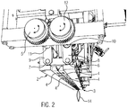
- Figure 2 shows a perspective view of the closed welding station 1 in a second viewing direction from obliquely below the welding station 1, so that the side of the welding station 1 with the two gear wheels 5, 12 can be seen.
- the two sealing arms 2, 3 were moved towards one another and the sealing station 1 was closed, so that the sealing strips 4 are now in contact or between the sealing strips 4 the upper regions of the foil pouches to be sealed are clamped or held by them.
- a synchronous movement of the first 2 and second 3 welding arms thus took place during closing, starting from the servo motor 13 arranged on the first drive axis 10.
- a filled foil bag 14 is shown as an example, which is held between two sealing bars 4 of the welding arms 2, 3 or is jammed.
- the contact pressure of the two welding arms 2, 3 can be increased by means of the servo motor 13, for example by monitoring and regulating the current consumption of the servo motor 13; the contact pressure can also remain the same or be reduced.
- the welded film bags 14 can be fed to further processes by means of the film bag transport device.
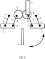
- Figure 3 shows a detail of the movement of the two welding arms 2, 3.
- This schematic side view shows the first 2 and the second welding arm 3 as well as the first 5 and the second gear wheel 12.
- the first welding arm 2 can be moved by the first drive shaft 10, at one end of which the servo motor 13 and at the other end of which the first gear wheel 5 is arranged.
- the first welding arm 2 also has axes 6, 7, the first axis 6 being connected to the first drive shaft 10 by means of a linkage 8 and the second axis 7 being connected to a third axis 11 parallel to the first drive shaft 10 by means of a linkage 9.
- the second welding arm 3 also has two axes 15, 16, the first axis 15 being connected to the second drive shaft 19 by means of a linkage 17 and the second axis 16 being connected to a third axis 20 parallel to the second drive shaft 19 by means of a linkage 18 .
- This gear drive with the two intermeshing gears 5, 12 transmits the movement of the first gear 5 to the second gear 12 and thus a drive movement of the first drive shaft 10, on which the servo motor 13 is arranged, to the second drive shaft 19.
- a synchronous movement of the first 2 and second 3 welding arms thus always takes place during the opening or closing of the welding station 1. Because of the arrangement of the two welding arms 2, 3 shown, it is thus possible to perform a rotary-parallel movement, whereby the desired precise execution of the movement and control of the contact pressure of the two welding arms 2, 3 can be guaranteed.
Landscapes
- Engineering & Computer Science (AREA)
- Mechanical Engineering (AREA)
- Package Closures (AREA)
Description
- Die Erfindung betrifft eine Schweißstation zum Verschweißen von Folienbeuteln gemäß dem Oberbegriff des Anspruchs 1 und ein entsprechendes Verfahren gemäß Anspruch 7.
- Es sind Folienbeutelschweißvorrichtungen zum Verschweißen von gefüllten Folienbeuteln bekannt, die eine Haltevorrichtung und eine Schweißstation umfassen. Um die Schweißstation für einen Schweißprozess in den oberen Bereich der unter ihr mittels der Haltevorrichtung angeordneten Folienbeutel zu bringen, wird die Schweißstation mittels eines Gestänges mit einem Kniehebel und einer Druckluftfeder relativ zu der Haltevorrichtung bewegt. Der Anpressdruck der Schweißstation an die zu schweißenden Folienbeutelhälften ergibt sich ebenfalls mittels des Gestänges mit Kniehebel und Druckluftfeder. Die Druckluftfeder begrenzt hierbei im Totpunkt des Kniehebels die maximal auftretende Kraft des Anpressdrucks.
- Durch die großen Massen von Gestänge, Kniehebel und Druckluftfeder, die bewegt werden müssen, ergibt sich eine Einschränkung in der Maschinengeschwindigkeit und somit der Anzahl der Folienbeutel, die pro Zeiteinheit verschweißt werden können, und auch in der Genauigkeit der Positionierung. Zudem kann der Anpressdruck nicht überprüft bzw. nicht genau gesteuert werden, was zu einem erhöhten Verschleiß der Haltevorrichtung und der Schweißstation führen kann. Auch können sich sehr lange Einstellzeiten der Gestänge nach Wartungsarbeiten an der Folienbeutelschweißvorrichtung ergeben. Zudem ist keine ausreichende Flexibilität in Bezug auf das Verschweißen verschiedener Folienbeuteltypen, z.B. mit unterschiedlichen Formaten, bei Verwendung einer solchen Folienbeutelschweißvorrichtung gegeben.
-
US 5,279,098 offenbart eine Vorrichtung und ein Verfahren zum Versiegeln für eine Maschine zum Formen, Füllen und Schließen von Packungen. Schlauchartig ausgebildetes Folienmaterial wird nach unten gezogen, um durch einen horizontalen Verschließer 210 zu einzelnen Beuteln gemacht zu werden. Der Verschließer 210 umfasst ein Paar querverlaufender Schließbacken 221, Dreheinrichtungen 211 zum Drehen der Schließbacken während sie zueinander immer in gleicher Richtung zeigen, Druckelemente 227 an den distalen Enden der Dreheinrichtungen 211 und Paare von linken und rechten beweglichen äußeren Rahmen 230 und entsprechenden inneren Rahmen 234, die so zusammengesetzt sind, dass die proximalen Endstücke der Dreheinrichtungen 211 aufeinander zu oder voneinander weg bewegt werden können. Jede der Dreheinrichtungen 211 umfasst rechte und linke Armteile 212 und eine Verbindungswelle 213. - Eine Schmidt-Kopplung 216 mit mehreren verbundenen Scheiben 216a, 216b, 216 c ist vorgesehen, um jeweils die Antriebskraft eines Servomotors von einer Antriebswelle 218 an eine Eingangswelle 215 der beiden Dreheinrichtungen 211 zu übertragen. Gegenseitig ineinandergreifende Zahnräder 219 sind an den Antriebswellen 218 für die beiden Dreheinrichtungen 211 vorgesehen, so dass diese in entgegengesetzte Richtungen rotieren.
-
EP 2 597 057 A1 offenbart eine Abfallverpackungsvorrichtung mit einer Fusionsdichtungsvorrichtung. Die Fusionsdichtungsvorrichtung umfasst zwei Schweißleisten 5 und eine Batterie mit einer maximalen Spannung von 20 V oder weniger, die den für den Schweißvorgang erforderlichen Strom liefert. Der Mechanismus wird durch eine manuelle Drehung einer Achse 1 aktiviert. Die Enden der freidrehbaren Achse 1 sind in einem Rahmen 6 stabilisiert und zwei Zahnräder 2 sind an jeder Seite der Achse 1 angeordnet. Die Zahnräder 2 der Achse greifen in Zahnräder 3, 4 von freidrehbaren Rahmen 7, 8, an denen die Schweißleisten 5 angeordnet sind. Durch das Ineinandergreifen der Zahnräder können die Schweißleisten 5 durch Drehung der Achse 1 in Kontakt gebracht bzw. wieder auseinander bewegt werden. Die Verschweißzeit wird durch einen Timer gesteuert. - Die Aufgabe der Erfindung besteht darin, eine Schweißstation zum Verschweißen von gefüllten Folienbeuteln und ein entsprechendes Verfahren zur Verfügung zu stellen, die einen erhöhten Durchsatz und einen verschleißfreieren Betrieb der Schweißstation ermöglichen.
- Die Aufgabe wird gelöst durch die Schweißstation nach Anspruch 1 und das Verfahren nach Anspruch 7. Bevorzugte Ausführungsformen und Weiterbildungen sind in den abhängigen Ansprüchen offenbart.
- Die Schweißstation in einer Folienbeutelabfüllvorrichtung zum Verschweißen von Folienbeuteln nach einem Füllprozess umfasst einen ersten und einen zweiten Schweißarm zum Verschweißen mehrerer gefüllter, nebeneinander angeordneter Folienbeutel, wobei der erste Schweißarm mit einer ersten Antriebswelle und der zweite Schweißarm mit einer zweiten Antriebswelle bewegbar sind. Ein Servomotor ist an der ersten Antriebswelle angeordnet, und eine Antriebsbewegung der ersten Antriebswelle wird von einem ersten Zahnrad an ein in das erste Zahnrad greifendes zweites Zahnrad und von dem zweiten Zahnrad an die zweite Antriebswelle übertragen. Die beiden Schweißarme können in einem geschlossenen Zustand zudem dazu ausgelegt sein, die gefüllten Folienbeutel für und/oder während des Schweißprozesses zu halten.
- Durch die Verwendung eines direkt an einer Antriebswelle angeordneten Servomotors entfallen die im Stand der Technik benötigten Gestänge, die Druckluftfeder und der Kniehebel. Somit besitzt die erfindungsgemäße Schweißstation im Vergleich zu einer Schweißstation des Stands der Technik eine geringere Masse, so dass eine höhere Betriebsgeschwindigkeit möglich ist. Zudem entfallen lange Einstellzeiten nach einer Wartung der Schweißstation.
- Durch die Anordnung des Servomotors an der ersten Antriebswelle, ist eine direkte Einwirkung des Servomotors auf diese Antriebswelle möglich, wodurch eine Genauigkeit in der Positionierung der Schweißarme gewährleistet wird. So können Verschleißerscheinungen der Schweißarme und Beschädigungen der Folienbeutel im zu verschweißenden Bereich minimiert werden, da beispielsweise der Anpressdruck der beiden Schweißarme an Typen der Folienbeutel und/oder den Zeitpunkt während des Schweißprozesses anpassbar ist.
- Bei den Folienbeuteln kann es sich jeweils um einen Beutel handeln, der in einem oberen Bereich offen ist, d.h., dass die beiden Folienhälften des Folienbeutels in diesem oberen Bereich keinen festen, verbindenden Kontakt aufweisen. Dieser obere Bereich kann nach dem Füllen des Folienbeutels mit einem Füllprodukt, z.B. mit einem flüssigen oder stückigen Lebensmittel oder einem flüssigen oder stückigen Futtermittel, mittels der Schweißstation verschweißt werden, so dass ein fester, verbindender Kontakt zwischen den beiden Hälften des Folienbeutels ausgebildet wird.
- Durch den Zahnradantrieb mit den beiden ineinandergreifenden Zahnrädern wird die Antriebsbewegung der ersten Antriebswelle an das erste Zahnrad und von dort an das zweite Zahnrad und somit an die zweite Antriebswelle übertragen. Da die erste Antriebswelle für eine Antriebsbewegung des ersten Schweißarms und die zweite Antriebswelle für eine Antriebsbewegung des zweiten Schweißarms zuständig ist, erfolgt immer eine synchrone Bewegung der beiden Schweißarme während des Öffnens bzw. Schließens. Aufgrund dieser Anordnung der Schweißarme und des beschriebenen Antriebs ist es somit möglich, eine rotativ-parallele Bewegung auszuführen, wodurch die gewünschte präzise Ausführung der Bewegung und eine Steuerung des Anpressdrucks der beiden Schweißarme gewährleistet werden können.
- Die Schweißarme umfassen Schweißleisten, wobei die Schweißleisten vorzugsweise zum Ultraschallschweißen ausgelegt sind. Das Schweißen mit Ultraschall ermöglicht einen vergleichsweise schnellen Schweißprozess.
- Zudem können die Schweißarme dazu ausgelegt sein, in einem geschlossenen Zustand einen Anpressdruck auszuüben. Die Stärke des Anpressdrucks kann veränderbar sein, so dass neben einem Halten von Folienbeuteln, zudem während des Schweißprozesses auch einer Materialdickenabnahme im Bereich der Schweißstelle Rechnung getragen werden kann.
- Die Schweißstation kann weiter eine Mess- und Steuervorrichtung für einen Strom des Servomotors umfassen. Die Mess- und Steuervorrichtung ermöglicht ein Messen des Stroms, der in dem Servomotor fließt und/oder ein Steuern des Stroms, so dass es möglich ist, den Strom während eines Schweißprozesses, davor oder danach zu verändern, d.h. zu steuern.
- Die Mess- und Steuervorrichtung kann dazu ausgelegt sein, den Anpressdruck der Schweißarme basierend auf Typangaben der Folienbeutel, wie Folienbeutelformaten, Füllvolumen und/oder Folienbeutelmaterialien, mittels des Stroms des Servomotors zu steuern. Dazu kann ein solcher Strom basierend auf den Typangaben berechnet werden. Der berechnete Sollstrom entspricht einem gewünschten Anpressdruck, der durch die Schweißarme ausgeübt werden soll. Die Typangaben der Folienbeutel können in die Mess- und Steuervorrichtung eingegeben und/oder aus einem Datenspeicher eingelesen werden. Der Datenspeicher kann ein Teil der Mess- und Steuervorrichtung sein oder der Datenspeicher kann ein davon unabhängiger Speicher sein.
- Es kann vorteilhaft sein, den Anpressdruck zu erhöhen, wenn Folienbeutel verschweißt werden sollen, deren Folienbeutelmaterial beispielsweise eine größere Dicke als zuvor verschweißte Folienbeutel aufweist oder deren Größe, d.h. das Format, größer ist als zuvor verschweißte Folienbeutel. Entsprechend kann es vorteilhaft sein, den Anpressdruck zu verringern, wenn Folienbeutel verschweißt werden sollen, deren Folienbeutelmaterial beispielsweise eine kleinere Dicke als zuvor verschweißte Folienbeutel aufweist oder deren Größe, d.h. das Format, kleiner ist als bei zuvor verschweißten Folienbeuteln.
- Die Schweißstation kann weiter eine Folienbeuteltransportvorrichtung umfassen. Mit der Folienbeuteltransportvorrichtung können die gefüllten Folienbeutel der Schweißstation für einen Schweißprozess zugeführt werden bzw. nach erfolgtem Verschweißen können die verschweißten Folienbeutel mit der Folienbeuteltransportvorrichtung weiteren Prozessen zugeführt werden.
- Ein erfindungsgemäßes Verfahren zum Verschweißen von Folienbeuteln nach einem Füllprozess mit einer Schweißstation wie oben oder weiter unten beschrieben, umfasst die Schritte: Positionieren der gefüllten Folienbeutel unterhalb der Schweißstation; Schließen der Schweißarme und Ausüben eines Anpressdrucks mit einem ersten Wert und Verschweißen der gefüllten Folienbeutel. Während des Verschweißens kann der Anpressdruck auf einen zweiten Wert erhöht werden.
- Nach dem Schritt des Verschweißens können ein Öffnen der Schweißarme und danach ein Entfernen der verschweißten Folienbeutel erfolgen, um diese für weitere Prozesse zu verwenden.
- Das Verfahren kann die weiteren Schritte umfassen: Eingeben von Typangaben der Folienbeutel und/oder Einlesen von Typangaben der Folienbeutel aus einem Datenspeicher; Berechnen eines Sollstroms des Servomotors basierend auf den Typangaben mittels einer Mess- und Steuervorrichtung und Steuern des Servomotors entsprechend des berechneten Sollstroms.
- Die beigefügten Figuren stellen beispielhaft zum besseren Verständnis und zur Veranschaulichung Aspekte der Erfindung dar. Es zeigt:
-
Figur 1 eine perspektivische Ansicht einer offenen Schweißstation in einer ersten Blickrichtung von schräg unten, -
Figur 2 eine perspektivische Ansicht der geschlossenen Schweißstation in einer zweiten Blickrichtung von schräg unten und -
Figur 3 ein Detail zur Bewegung der beiden Schweißarme. -
Figur 1 zeigt eine perspektivische Ansicht einer offenen Schweißstation 1 in einer ersten Blickrichtung von schräg unterhalb der Schweißstation 1, so dass die Seite der Schweißstation 1 mit dem Servomotor 13 zu sehen ist. Die Schweißstation 1 umfasst zwei relativ zueinander bewegbare Schweißarme 2, 3. Die Schweißarme 2, 3 sind spiegelsymmetrisch und weisen in dem Bereich, in dem sie in Kontakt gebracht werden können, wenn sich keine Folienbeutel zwischen ihnen befinden, jeweils mehrere, nebeneinander entlang des Schweißarms 2, 3 angeordnete Schweißleisten 4 auf, die bei einer geschlossenen Schweißstation 1 zum Halten und Verschweißen von gefüllten Folienbeuteln dienen. Die Folienbeutel werden in einem gefüllten, noch offenen Zustand der Schweißstation 1 mit einer Folienbeuteltransportvorrichtung (nicht dargestellt) zugeführt, in der sich die Folienbeutel in einer solchen Ausrichtung relativ zu der Schweißstation 1 befinden, dass bei einem Schließen der Schweißarme 2, 3 die Folienbeutel in einem oberen Bereich zwischen den jeweiligen Schweißleisten 4 gehalten und dann auch verschweißt werden können. - Das Öffnen bzw. Schließen der Schweißarme 2, 3 erfolgt mittels des Servomotors 13, der direkt an einer ersten Antriebswelle 10 (hier nicht sichtbar; siehe
Figur 2 ) angeordnet ist. Durch diese Anordnung ist eine direkte Einwirkung des Servomotors 13 auf die erste Antriebswelle 10 möglich, wodurch die Bewegung der beiden Schweißarme 2, 3 besser gesteuert werden kann und eine Genauigkeit in der Positionierung der Schweißarme 2, 3 gewährleistet wird. Dadurch können Verschleißerscheinungen der Schweißarme 2, 3 und Beschädigungen im zu verschweißenden Bereich der Folienbeutel minimiert werden, da beispielsweise der Anpressdruck der beiden Schweißarme 2, 3 an Typen der Folienbeutel und/oder den Zeitpunkt während des Schweißprozesses anpassbar ist. - Der erste Schweißarm 2 ist durch die erste Antriebswelle 10 bewegbar, an deren einem Ende der Servomotor 13 und an deren anderem Ende ein erstes Zahnrad 5 (hier nicht sichtbar; siehe
Figur 2 ) angeordnet ist. Der erste Schweißarm 2 weist zwei Achsen 6, 7 auf (hier nicht sichtbar; sieheFigur 2 ), wobei die erste Achse 6 mittels eines ersten Gestänges 8 mit der ersten Antriebswelle 10 und die zweite Achse 7 mittels eines zweiten Gestänges 9 mit einer dritten, zu der ersten Antriebswelle 10 parallelen Achse 11 verbunden sind. - Der zweite Schweißarm 3 weist ebenfalls zwei Achsen 15, 16 auf (hier nicht sichtbar; siehe
Figur 3 ), wobei die erste Achse 15 mittels eines ersten Gestänges 17 mit der zweiten Antriebswelle 19 und somit mit einem zweiten Zahnrad 12 (hier nicht sichtbar; sieheFigur 2 ) und die zweite Achse 16 mittels eines zweiten Gestänges 18 mit einer dritten, zu der zweiten Antriebswelle 19 parallelen Achse 20 verbunden sind (hier nicht dargestellt; sieheFigur 3 ). -
Figur 2 zeigt eine perspektivische Ansicht der geschlossenen Schweißstation 1 in einer zweiten Blickrichtung von schräg unterhalb der Schweißstation 1, so dass die Seite der Schweißstation 1 mit den beiden Zahnrädern 5, 12 zu sehen ist. Die beiden Schweißarme 2, 3 wurden aufeinander zubewegt und die Schweißstation 1 geschlossen, so dass die Schweißleisten 4 nun in Kontakt bzw. zwischen den Schweißleisten 4 die oberen Bereiche der zu verschweißenden Folienbeutel eingeklemmt sind bzw. davon gehalten werden. Zwischen den beiden Schweißarmen 2, 3 besteht ein Anpressdruck, dessen Stärke durch den Servomotor 13 steuerbar ist. - Die Schließbewegung der beiden Schweißarme wurde durch den Zahnradantrieb mit den ineinandergreifenden ersten 5 und zweiten Zahnrädern 12 ausgeführt, wobei die Bewegung des ersten Zahnrads 5 an das zweite Zahnrad 12 übertragen wurde. Somit erfolgte eine synchrone Bewegung des ersten 2 und des zweiten 3 Schweißarms während des Schließens ausgehend von dem an der ersten Antriebsachse 10 angeordneten Servomotor 13. Exemplarisch ist ein gefüllter Folienbeutel 14 gezeigt, der zwischen zwei Schweißleisten 4 der Schweißarme 2, 3 gehalten wird bzw. eingeklemmt ist.
- Während des Schweißprozesses kann der Anpressdruck der beiden Schweißarme 2, 3 mittels des Servomotors 13 erhöht werden, beispielsweise durch eine Überwachung und Regelung der Stromaufnahme des Servomotors 13; der Anpressdruck kann aber auch gleich bleiben oder verkleinert werden. Durch das Nachregeln des Anpressdrucks der beiden Schweißarme 2, 3 mittels des direkt an der Antriebswelle 10 angebrachten Servomotors 13, nachdem der Schweißprozess begonnen hat, kann dafür gesorgt werden, dass die beiden Folienbeutelhälften auch bei einer eventuellen Materialdickenabnahme im Bereich der Schweißstelle weiter aneinander liegen.
- Nach dem Verschweißen und einem Öffnen der Schweißarme 2, 3 können die verschweißten Folienbeutel 14 mittels der Folienbeuteltransportvorrichtung weiteren Prozessen zugeführt werden.
-
Figur 3 zeigt ein Detail zur Bewegung der beiden Schweißarme 2, 3. In dieser schematischen Seitenansicht sind der erste 2 und der zweite Schweißarm 3 sowie das erste 5 und das zweite Zahnrad 12 zu sehen. Der erste Schweißarm 2 ist durch die erste Antriebswelle 10 bewegbar, an deren einem Ende der Servomotor 13 und an deren anderem Ende das erste Zahnrad 5 angeordnet ist. Der erste Schweißarm 2 weist zudem Achsen 6, 7 auf, wobei die erste Achse 6 mittels eines Gestänges 8 mit der ersten Antriebswelle 10 und die zweite Achse 7 mittels eines Gestänges 9 mit einer dritten, zu der ersten Antriebswelle 10 parallelen Achse 11 verbunden sind. - Der zweite Schweißarm 3 weist ebenfalls zwei Achsen 15, 16 auf, wobei die erste Achse 15 mittels eines Gestänges 17 mit der zweiten Antriebswelle 19 und die zweite Achse 16 mittels eines Gestänges 18 mit einer dritten, zu der zweiten Antriebswelle 19 parallelen Achse 20 verbunden sind.
- Durch diesen Zahnradantrieb mit den zwei ineinandergreifenden Zahnrädern 5, 12 wird die Bewegung des ersten Zahnrads 5 an das zweite Zahnrad 12 und somit eine Antriebsbewegung der ersten Antriebswelle 10, an der der Servomotor 13 angeordnet ist, an die zweite Antriebswelle 19 übertragen. Somit erfolgt immer eine synchrone Bewegung des ersten 2 und des zweiten 3 Schweißarms während des Öffnens bzw. Schließens der Schweißstation 1. Aufgrund der dargestellten Anordnung der beiden Schweißarme 2, 3 ist es somit möglich, eine rotativ-parallele Bewegung auszuführen, wodurch die gewünschte präzise Ausführung der Bewegung und eine Steuerung des Anpressdrucks der beiden Schweißarme 2, 3 gewährleistet werden können.
Claims (11)
- Schweißstation (1) in einer Folienbeutelabfüllvorrichtung zum Verschweißen von Folienbeuteln (14) nach einem Füllprozess, wobei die Schweißstation (1) einen ersten Schweißarm (2) und einen zweiten Schweißarm (3) zum Verschweißen mehrerer gefüllter, nebeneinander angeordneter Folienbeutel (14) umfasst, wobei der erste Schweißarm (2) und der zweite Schweißarm (3) spiegelsymmetrisch sind, wobei der erste Schweißarm (2) mit einer ersten Antriebswelle (10) und der zweite Schweißarm (3) mit einer zweiten Antriebswelle (19) bewegbar sind, und wobei die Schweißstation (1) einen Servomotor (13) umfasst, der an der ersten Antriebswelle (10) angeordnet ist und wobei eine Antriebsbewegung der ersten Antriebswelle (10) von einem ersten Zahnrad (5) an ein in das erste Zahnrad (5) greifendes zweites Zahnrad (12) und von dem zweiten Zahnrad (12) an die zweite Antriebswelle (19) übertragen wird,
dadurch gekennzeichnet, dass
die Schweißarme (2, 3) jeweils mehrere, nebeneinander entlang der Schweißarme (2, 3) angeordnete Schweißleisten (4) umfassen. - Schweißstation nach Anspruch 1, wobei die Schweißleisten (4) zum Ultraschallschweißen ausgelegt sind.
- Schweißstation nach Anspruch 1 oder 2, wobei die Schweißarme (2, 3) dazu ausgelegt sind, in einem geschlossenen Zustand einen Anpressdruck auszuüben.
- Schweißstation nach einem der Ansprüche 1 bis 3, die weiter eine Mess- und Steuervorrichtung für einen Strom des Servomotors (13) umfasst.
- Schweißstation nach Anspruch 4, soweit rückbezogen auf Anspruch 3, wobei die Mess- und Steuervorrichtung dazu ausgelegt ist, den Anpressdruck basierend auf Typangaben der Folienbeutel (14) mittels des Stroms des Servomotors (13) zu steuern.
- Schweißstation nach einem der Ansprüche 1 bis 5, die weiter eine Folienbeuteltransportvorrichtung umfasst.
- Verfahren zum Verschweißen von Folienbeuteln (14) nach einem Füllprozess mit der Schweißstation (1) nach einem der Ansprüche 1 bis 6 mit den Schritten:- Positionieren der gefüllten Folienbeutel (14) unterhalb der Schweißstation (1),- Schließen der Schweißarme (2, 3) und Ausüben eines Anpressdrucks mit einem ersten Wert und- Verschweißen der gefüllten Folienbeutel (14).
- Verfahren nach Anspruch 7, wobei während des Verschweißens der Anpressdruck auf einen zweiten Wert erhöht wird.
- Verfahren nach Anspruch 7 oder 8, das nach dem Schritt des Verschweißens ein Öffnen der Schweißarme (2, 3) umfasst.
- Verfahren nach Anspruch 9, bei dem anschließend ein Entfernen der verschweißten Folienbeutel (14) erfolgt.
- Verfahren nach einem der Ansprüche 7 bis 10 mit den weiteren Schritten:- Eingeben von Typangaben der Folienbeutel (14) und/oder Auslesen von Typangaben der Folienbeutel (14) aus einem Datenspeicher,- Berechnen eines Sollstroms des Servomotors (13) basierend auf den Typangaben mittels einer Mess- und Steuervorrichtung,- Steuern des Servomotors (13) entsprechend des berechneten Sollstroms.
Priority Applications (3)
| Application Number | Priority Date | Filing Date | Title |
|---|---|---|---|
| ES15180151T ES2807560T3 (es) | 2015-08-07 | 2015-08-07 | Estación de soldadura para la soldadura de bolsas de láminas y procedimiento asociado |
| EP15180151.1A EP3127683B1 (de) | 2015-08-07 | 2015-08-07 | Schweissstation zum verschweissen von folienbeuteln und verfahren dazu |
| US15/227,430 US10793306B2 (en) | 2015-08-07 | 2016-08-03 | Sealing station for sealing of film bags and corresponding method |
Applications Claiming Priority (1)
| Application Number | Priority Date | Filing Date | Title |
|---|---|---|---|
| EP15180151.1A EP3127683B1 (de) | 2015-08-07 | 2015-08-07 | Schweissstation zum verschweissen von folienbeuteln und verfahren dazu |
Publications (2)
| Publication Number | Publication Date |
|---|---|
| EP3127683A1 EP3127683A1 (de) | 2017-02-08 |
| EP3127683B1 true EP3127683B1 (de) | 2020-04-22 |
Family
ID=53969128
Family Applications (1)
| Application Number | Title | Priority Date | Filing Date |
|---|---|---|---|
| EP15180151.1A Active EP3127683B1 (de) | 2015-08-07 | 2015-08-07 | Schweissstation zum verschweissen von folienbeuteln und verfahren dazu |
Country Status (3)
| Country | Link |
|---|---|
| US (1) | US10793306B2 (de) |
| EP (1) | EP3127683B1 (de) |
| ES (1) | ES2807560T3 (de) |
Families Citing this family (1)
| Publication number | Priority date | Publication date | Assignee | Title |
|---|---|---|---|---|
| US11136511B2 (en) * | 2019-05-23 | 2021-10-05 | Evonik Operations Gmbh | Reactivated hydroprocessing catalysts for use in sulfur abatement |
Family Cites Families (4)
| Publication number | Priority date | Publication date | Assignee | Title |
|---|---|---|---|---|
| US5279098A (en) * | 1990-07-31 | 1994-01-18 | Ishida Scales Mfg. Co., Ltd. | Apparatus for and method of transverse sealing for a form-fill-seal packaging machine |
| US6088994A (en) * | 1998-01-20 | 2000-07-18 | Ishida Co., Ltd. | Packaging machine incorporating device for adjusting position for cutting bags |
| US7490451B2 (en) * | 2005-10-18 | 2009-02-17 | Illinois Tool Works Inc. | Method and apparatus for making block bottom pillow top bags |
| DE202012013351U1 (de) * | 2011-11-23 | 2016-06-27 | Flexopack S.A. | Abfallverpackungssystem mit einer Schmelzversiegelungseinrichtung |
-
2015
- 2015-08-07 ES ES15180151T patent/ES2807560T3/es active Active
- 2015-08-07 EP EP15180151.1A patent/EP3127683B1/de active Active
-
2016
- 2016-08-03 US US15/227,430 patent/US10793306B2/en active Active
Non-Patent Citations (1)
| Title |
|---|
| None * |
Also Published As
| Publication number | Publication date |
|---|---|
| ES2807560T3 (es) | 2021-02-23 |
| EP3127683A1 (de) | 2017-02-08 |
| US10793306B2 (en) | 2020-10-06 |
| US20170036796A1 (en) | 2017-02-09 |
Similar Documents
| Publication | Publication Date | Title |
|---|---|---|
| DE3907208C2 (de) | ||
| EP3212381B1 (de) | Vorrichtung und verfahren zur herstellung von kunststoffbeuteln | |
| DE1586060A1 (de) | Vorrichtung zum Fuellen und Verschliessen von Verpackungen | |
| DE3515846A1 (de) | Verfahren und anordnung zum steuern einer verpackungsmaschine | |
| EP1780000B1 (de) | Vorrichtung und Verfahren zur Herstellung von Kunststoffbeuteln | |
| DE2131906B2 (de) | Vorrichtung zum Herstellen mit Flüssigkeit gefüllter Packungen | |
| EP0255474A2 (de) | Vorrichtung zur Bildung von Schlauchbeutelpackungen | |
| WO2015124396A9 (de) | Vorrichtung und verfahren zur vorfaltung von packungsmänteln | |
| DE2224407B2 (de) | Vorrichtung zum Querschweißen und/oder Querschneiden von laufendem Bahnmaterial | |
| EP3127683B1 (de) | Schweissstation zum verschweissen von folienbeuteln und verfahren dazu | |
| DE3332308C2 (de) | Vorrichtung zum zyklischen Öffnen und Schließen der Siegelbacken einer Schlauchbeutelmaschine | |
| EP2387495B1 (de) | VORRICHTUNG ZUM SCHWEIßEN UND TRENNEN VON PACKSTOFFEN | |
| DE102004047207A1 (de) | Verfahren und Vorrichtung zum Bewegen einer Schweißbacke | |
| WO2011060749A1 (de) | Formschulter und vorrichtung zum herstellen von schlauchbeuteln | |
| DE102017121572A1 (de) | Verfahren und Vorrichtung zum Herstellen von Schlauchbeuteln | |
| DE102009044120A1 (de) | Heißsiegeleinheit und Verfahren zur Steuerung einer Heißsiegeleinheit für eine Flachbeutelmaschine | |
| DE2337939A1 (de) | Verfahren zur kontinuierlichen herstellung von fluessigkeitsverpackungen und vorrichtung zur durchfuehrung des verfahrens | |
| EP3127825B1 (de) | Aufblasstation zum aufblasen von folienbeuteln und verfahren dazu | |
| EP3888893A1 (de) | Verfahren und vorrichtung zum herstellen von beuteln | |
| EP3630460B1 (de) | Verfahren zur funktionsüberwachung einer schlauchbeutelmaschine | |
| DE102007003930B4 (de) | Schlauchbeutelmaschine | |
| DE102007004140B4 (de) | Schlauchbeutelmaschine | |
| DE102020208644B4 (de) | Vorrichtung und Verfahren zur Anordnung von Produkten im Bereich einer Quersiegeleinrichtung einer Schlauchbeutelverpackungsmaschine | |
| DE505188C (de) | Maschine zur Erzeugung von Briefumschlag-Formschnitten | |
| DE19704174C2 (de) | Schlauchbeutelmaschine |
Legal Events
| Date | Code | Title | Description |
|---|---|---|---|
| PUAI | Public reference made under article 153(3) epc to a published international application that has entered the european phase |
Free format text: ORIGINAL CODE: 0009012 |
|
| STAA | Information on the status of an ep patent application or granted ep patent |
Free format text: STATUS: THE APPLICATION HAS BEEN PUBLISHED |
|
| AK | Designated contracting states |
Kind code of ref document: A1 Designated state(s): AL AT BE BG CH CY CZ DE DK EE ES FI FR GB GR HR HU IE IS IT LI LT LU LV MC MK MT NL NO PL PT RO RS SE SI SK SM TR |
|
| AX | Request for extension of the european patent |
Extension state: BA ME |
|
| STAA | Information on the status of an ep patent application or granted ep patent |
Free format text: STATUS: REQUEST FOR EXAMINATION WAS MADE |
|
| 17P | Request for examination filed |
Effective date: 20170802 |
|
| RBV | Designated contracting states (corrected) |
Designated state(s): AL AT BE BG CH CY CZ DE DK EE ES FI FR GB GR HR HU IE IS IT LI LT LU LV MC MK MT NL NO PL PT RO RS SE SI SK SM TR |
|
| RAP1 | Party data changed (applicant data changed or rights of an application transferred) |
Owner name: INDAG POUCH PARTNERS GMBH |
|
| STAA | Information on the status of an ep patent application or granted ep patent |
Free format text: STATUS: EXAMINATION IS IN PROGRESS |
|
| 17Q | First examination report despatched |
Effective date: 20190624 |
|
| GRAP | Despatch of communication of intention to grant a patent |
Free format text: ORIGINAL CODE: EPIDOSNIGR1 |
|
| STAA | Information on the status of an ep patent application or granted ep patent |
Free format text: STATUS: GRANT OF PATENT IS INTENDED |
|
| RIC1 | Information provided on ipc code assigned before grant |
Ipc: B65B 65/02 20060101ALI20191108BHEP Ipc: B65B 9/00 20060101ALN20191108BHEP Ipc: B29C 65/08 20060101AFI20191108BHEP Ipc: B65B 51/14 20060101ALI20191108BHEP Ipc: B65B 51/22 20060101ALI20191108BHEP |
|
| INTG | Intention to grant announced |
Effective date: 20191211 |
|
| GRAS | Grant fee paid |
Free format text: ORIGINAL CODE: EPIDOSNIGR3 |
|
| GRAA | (expected) grant |
Free format text: ORIGINAL CODE: 0009210 |
|
| STAA | Information on the status of an ep patent application or granted ep patent |
Free format text: STATUS: THE PATENT HAS BEEN GRANTED |
|
| AK | Designated contracting states |
Kind code of ref document: B1 Designated state(s): AL AT BE BG CH CY CZ DE DK EE ES FI FR GB GR HR HU IE IS IT LI LT LU LV MC MK MT NL NO PL PT RO RS SE SI SK SM TR |
|
| REG | Reference to a national code |
Ref country code: CH Ref legal event code: EP |
|
| REG | Reference to a national code |
Ref country code: IE Ref legal event code: FG4D Free format text: LANGUAGE OF EP DOCUMENT: GERMAN |
|
| REG | Reference to a national code |
Ref country code: DE Ref legal event code: R096 Ref document number: 502015012336 Country of ref document: DE |
|
| REG | Reference to a national code |
Ref country code: AT Ref legal event code: REF Ref document number: 1259530 Country of ref document: AT Kind code of ref document: T Effective date: 20200515 |
|
| RAP2 | Party data changed (patent owner data changed or rights of a patent transferred) |
Owner name: POUCH PARTNERS GMBH |
|
| REG | Reference to a national code |
Ref country code: LT Ref legal event code: MG4D |
|
| REG | Reference to a national code |
Ref country code: NL Ref legal event code: MP Effective date: 20200422 |
|
| PG25 | Lapsed in a contracting state [announced via postgrant information from national office to epo] |
Ref country code: NL Free format text: LAPSE BECAUSE OF FAILURE TO SUBMIT A TRANSLATION OF THE DESCRIPTION OR TO PAY THE FEE WITHIN THE PRESCRIBED TIME-LIMIT Effective date: 20200422 Ref country code: SE Free format text: LAPSE BECAUSE OF FAILURE TO SUBMIT A TRANSLATION OF THE DESCRIPTION OR TO PAY THE FEE WITHIN THE PRESCRIBED TIME-LIMIT Effective date: 20200422 Ref country code: LT Free format text: LAPSE BECAUSE OF FAILURE TO SUBMIT A TRANSLATION OF THE DESCRIPTION OR TO PAY THE FEE WITHIN THE PRESCRIBED TIME-LIMIT Effective date: 20200422 Ref country code: PT Free format text: LAPSE BECAUSE OF FAILURE TO SUBMIT A TRANSLATION OF THE DESCRIPTION OR TO PAY THE FEE WITHIN THE PRESCRIBED TIME-LIMIT Effective date: 20200824 Ref country code: IS Free format text: LAPSE BECAUSE OF FAILURE TO SUBMIT A TRANSLATION OF THE DESCRIPTION OR TO PAY THE FEE WITHIN THE PRESCRIBED TIME-LIMIT Effective date: 20200822 Ref country code: FI Free format text: LAPSE BECAUSE OF FAILURE TO SUBMIT A TRANSLATION OF THE DESCRIPTION OR TO PAY THE FEE WITHIN THE PRESCRIBED TIME-LIMIT Effective date: 20200422 Ref country code: NO Free format text: LAPSE BECAUSE OF FAILURE TO SUBMIT A TRANSLATION OF THE DESCRIPTION OR TO PAY THE FEE WITHIN THE PRESCRIBED TIME-LIMIT Effective date: 20200722 Ref country code: GR Free format text: LAPSE BECAUSE OF FAILURE TO SUBMIT A TRANSLATION OF THE DESCRIPTION OR TO PAY THE FEE WITHIN THE PRESCRIBED TIME-LIMIT Effective date: 20200723 |
|
| PG25 | Lapsed in a contracting state [announced via postgrant information from national office to epo] |
Ref country code: LV Free format text: LAPSE BECAUSE OF FAILURE TO SUBMIT A TRANSLATION OF THE DESCRIPTION OR TO PAY THE FEE WITHIN THE PRESCRIBED TIME-LIMIT Effective date: 20200422 Ref country code: RS Free format text: LAPSE BECAUSE OF FAILURE TO SUBMIT A TRANSLATION OF THE DESCRIPTION OR TO PAY THE FEE WITHIN THE PRESCRIBED TIME-LIMIT Effective date: 20200422 Ref country code: BG Free format text: LAPSE BECAUSE OF FAILURE TO SUBMIT A TRANSLATION OF THE DESCRIPTION OR TO PAY THE FEE WITHIN THE PRESCRIBED TIME-LIMIT Effective date: 20200722 Ref country code: HR Free format text: LAPSE BECAUSE OF FAILURE TO SUBMIT A TRANSLATION OF THE DESCRIPTION OR TO PAY THE FEE WITHIN THE PRESCRIBED TIME-LIMIT Effective date: 20200422 |
|
| PG25 | Lapsed in a contracting state [announced via postgrant information from national office to epo] |
Ref country code: AL Free format text: LAPSE BECAUSE OF FAILURE TO SUBMIT A TRANSLATION OF THE DESCRIPTION OR TO PAY THE FEE WITHIN THE PRESCRIBED TIME-LIMIT Effective date: 20200422 |
|
| REG | Reference to a national code |
Ref country code: DE Ref legal event code: R097 Ref document number: 502015012336 Country of ref document: DE |
|
| PG25 | Lapsed in a contracting state [announced via postgrant information from national office to epo] |
Ref country code: RO Free format text: LAPSE BECAUSE OF FAILURE TO SUBMIT A TRANSLATION OF THE DESCRIPTION OR TO PAY THE FEE WITHIN THE PRESCRIBED TIME-LIMIT Effective date: 20200422 Ref country code: CZ Free format text: LAPSE BECAUSE OF FAILURE TO SUBMIT A TRANSLATION OF THE DESCRIPTION OR TO PAY THE FEE WITHIN THE PRESCRIBED TIME-LIMIT Effective date: 20200422 Ref country code: SM Free format text: LAPSE BECAUSE OF FAILURE TO SUBMIT A TRANSLATION OF THE DESCRIPTION OR TO PAY THE FEE WITHIN THE PRESCRIBED TIME-LIMIT Effective date: 20200422 Ref country code: EE Free format text: LAPSE BECAUSE OF FAILURE TO SUBMIT A TRANSLATION OF THE DESCRIPTION OR TO PAY THE FEE WITHIN THE PRESCRIBED TIME-LIMIT Effective date: 20200422 Ref country code: DK Free format text: LAPSE BECAUSE OF FAILURE TO SUBMIT A TRANSLATION OF THE DESCRIPTION OR TO PAY THE FEE WITHIN THE PRESCRIBED TIME-LIMIT Effective date: 20200422 |
|
| REG | Reference to a national code |
Ref country code: ES Ref legal event code: FG2A Ref document number: 2807560 Country of ref document: ES Kind code of ref document: T3 Effective date: 20210223 |
|
| PG25 | Lapsed in a contracting state [announced via postgrant information from national office to epo] |
Ref country code: SK Free format text: LAPSE BECAUSE OF FAILURE TO SUBMIT A TRANSLATION OF THE DESCRIPTION OR TO PAY THE FEE WITHIN THE PRESCRIBED TIME-LIMIT Effective date: 20200422 Ref country code: PL Free format text: LAPSE BECAUSE OF FAILURE TO SUBMIT A TRANSLATION OF THE DESCRIPTION OR TO PAY THE FEE WITHIN THE PRESCRIBED TIME-LIMIT Effective date: 20200422 |
|
| PLBE | No opposition filed within time limit |
Free format text: ORIGINAL CODE: 0009261 |
|
| STAA | Information on the status of an ep patent application or granted ep patent |
Free format text: STATUS: NO OPPOSITION FILED WITHIN TIME LIMIT |
|
| 26N | No opposition filed |
Effective date: 20210125 |
|
| PG25 | Lapsed in a contracting state [announced via postgrant information from national office to epo] |
Ref country code: MC Free format text: LAPSE BECAUSE OF FAILURE TO SUBMIT A TRANSLATION OF THE DESCRIPTION OR TO PAY THE FEE WITHIN THE PRESCRIBED TIME-LIMIT Effective date: 20200422 |
|
| REG | Reference to a national code |
Ref country code: CH Ref legal event code: PL |
|
| GBPC | Gb: european patent ceased through non-payment of renewal fee |
Effective date: 20200807 |
|
| PG25 | Lapsed in a contracting state [announced via postgrant information from national office to epo] |
Ref country code: LU Free format text: LAPSE BECAUSE OF NON-PAYMENT OF DUE FEES Effective date: 20200807 Ref country code: LI Free format text: LAPSE BECAUSE OF NON-PAYMENT OF DUE FEES Effective date: 20200831 Ref country code: CH Free format text: LAPSE BECAUSE OF NON-PAYMENT OF DUE FEES Effective date: 20200831 |
|
| REG | Reference to a national code |
Ref country code: BE Ref legal event code: MM Effective date: 20200831 |
|
| PG25 | Lapsed in a contracting state [announced via postgrant information from national office to epo] |
Ref country code: SI Free format text: LAPSE BECAUSE OF FAILURE TO SUBMIT A TRANSLATION OF THE DESCRIPTION OR TO PAY THE FEE WITHIN THE PRESCRIBED TIME-LIMIT Effective date: 20200422 |
|
| PG25 | Lapsed in a contracting state [announced via postgrant information from national office to epo] |
Ref country code: BE Free format text: LAPSE BECAUSE OF NON-PAYMENT OF DUE FEES Effective date: 20200831 Ref country code: IE Free format text: LAPSE BECAUSE OF NON-PAYMENT OF DUE FEES Effective date: 20200807 Ref country code: GB Free format text: LAPSE BECAUSE OF NON-PAYMENT OF DUE FEES Effective date: 20200807 |
|
| REG | Reference to a national code |
Ref country code: AT Ref legal event code: MM01 Ref document number: 1259530 Country of ref document: AT Kind code of ref document: T Effective date: 20200807 |
|
| PG25 | Lapsed in a contracting state [announced via postgrant information from national office to epo] |
Ref country code: AT Free format text: LAPSE BECAUSE OF NON-PAYMENT OF DUE FEES Effective date: 20200807 |
|
| PGFP | Annual fee paid to national office [announced via postgrant information from national office to epo] |
Ref country code: FR Payment date: 20210820 Year of fee payment: 7 Ref country code: IT Payment date: 20210831 Year of fee payment: 7 |
|
| PGFP | Annual fee paid to national office [announced via postgrant information from national office to epo] |
Ref country code: ES Payment date: 20210901 Year of fee payment: 7 Ref country code: DE Payment date: 20210826 Year of fee payment: 7 |
|
| PG25 | Lapsed in a contracting state [announced via postgrant information from national office to epo] |
Ref country code: TR Free format text: LAPSE BECAUSE OF FAILURE TO SUBMIT A TRANSLATION OF THE DESCRIPTION OR TO PAY THE FEE WITHIN THE PRESCRIBED TIME-LIMIT Effective date: 20200422 Ref country code: MT Free format text: LAPSE BECAUSE OF FAILURE TO SUBMIT A TRANSLATION OF THE DESCRIPTION OR TO PAY THE FEE WITHIN THE PRESCRIBED TIME-LIMIT Effective date: 20200422 Ref country code: CY Free format text: LAPSE BECAUSE OF FAILURE TO SUBMIT A TRANSLATION OF THE DESCRIPTION OR TO PAY THE FEE WITHIN THE PRESCRIBED TIME-LIMIT Effective date: 20200422 |
|
| PG25 | Lapsed in a contracting state [announced via postgrant information from national office to epo] |
Ref country code: MK Free format text: LAPSE BECAUSE OF FAILURE TO SUBMIT A TRANSLATION OF THE DESCRIPTION OR TO PAY THE FEE WITHIN THE PRESCRIBED TIME-LIMIT Effective date: 20200422 |
|
| REG | Reference to a national code |
Ref country code: DE Ref legal event code: R119 Ref document number: 502015012336 Country of ref document: DE |
|
| PG25 | Lapsed in a contracting state [announced via postgrant information from national office to epo] |
Ref country code: IT Free format text: LAPSE BECAUSE OF NON-PAYMENT OF DUE FEES Effective date: 20220807 Ref country code: FR Free format text: LAPSE BECAUSE OF NON-PAYMENT OF DUE FEES Effective date: 20220831 Ref country code: DE Free format text: LAPSE BECAUSE OF NON-PAYMENT OF DUE FEES Effective date: 20230301 |
|
| REG | Reference to a national code |
Ref country code: ES Ref legal event code: FD2A Effective date: 20230927 |
|
| PG25 | Lapsed in a contracting state [announced via postgrant information from national office to epo] |
Ref country code: ES Free format text: LAPSE BECAUSE OF NON-PAYMENT OF DUE FEES Effective date: 20220808 |