EP3126818B1 - Method and device for drug screening - Google Patents
Method and device for drug screening Download PDFInfo
- Publication number
- EP3126818B1 EP3126818B1 EP15713796.9A EP15713796A EP3126818B1 EP 3126818 B1 EP3126818 B1 EP 3126818B1 EP 15713796 A EP15713796 A EP 15713796A EP 3126818 B1 EP3126818 B1 EP 3126818B1
- Authority
- EP
- European Patent Office
- Prior art keywords
- cells
- substrate
- lens
- optical signal
- sensor
- Prior art date
- Legal status (The legal status is an assumption and is not a legal conclusion. Google has not performed a legal analysis and makes no representation as to the accuracy of the status listed.)
- Active
Links
- 238000007877 drug screening Methods 0.000 title claims description 30
- 238000000034 method Methods 0.000 title claims description 23
- 210000004027 cell Anatomy 0.000 claims description 219
- 239000000758 substrate Substances 0.000 claims description 130
- 230000003287 optical effect Effects 0.000 claims description 87
- 229940079593 drug Drugs 0.000 claims description 32
- 239000003814 drug Substances 0.000 claims description 32
- 210000002064 heart cell Anatomy 0.000 claims description 21
- 230000010261 cell growth Effects 0.000 claims description 16
- 238000001514 detection method Methods 0.000 claims description 11
- 230000002596 correlated effect Effects 0.000 claims description 8
- 238000012545 processing Methods 0.000 claims description 7
- 230000001276 controlling effect Effects 0.000 claims description 4
- 230000005855 radiation Effects 0.000 claims description 3
- 230000008901 benefit Effects 0.000 description 26
- 230000008602 contraction Effects 0.000 description 26
- 238000003384 imaging method Methods 0.000 description 11
- 238000012360 testing method Methods 0.000 description 10
- 239000002073 nanorod Substances 0.000 description 9
- 238000002474 experimental method Methods 0.000 description 7
- 238000005286 illumination Methods 0.000 description 6
- 238000005259 measurement Methods 0.000 description 6
- 229910052751 metal Inorganic materials 0.000 description 6
- 239000002184 metal Substances 0.000 description 6
- XUIMIQQOPSSXEZ-UHFFFAOYSA-N Silicon Chemical compound [Si] XUIMIQQOPSSXEZ-UHFFFAOYSA-N 0.000 description 5
- 230000005540 biological transmission Effects 0.000 description 5
- 230000000694 effects Effects 0.000 description 5
- 239000010410 layer Substances 0.000 description 5
- 239000000463 material Substances 0.000 description 5
- 229910052710 silicon Inorganic materials 0.000 description 5
- 239000010703 silicon Substances 0.000 description 5
- 230000001427 coherent effect Effects 0.000 description 4
- 239000012530 fluid Substances 0.000 description 4
- 206010048610 Cardiotoxicity Diseases 0.000 description 3
- 238000004458 analytical method Methods 0.000 description 3
- 239000012620 biological material Substances 0.000 description 3
- 210000004413 cardiac myocyte Anatomy 0.000 description 3
- 231100000259 cardiotoxicity Toxicity 0.000 description 3
- 239000011521 glass Substances 0.000 description 3
- 230000010247 heart contraction Effects 0.000 description 3
- 239000013307 optical fiber Substances 0.000 description 3
- 230000035899 viability Effects 0.000 description 3
- AOJJSUZBOXZQNB-TZSSRYMLSA-N Doxorubicin Chemical compound O([C@H]1C[C@@](O)(CC=2C(O)=C3C(=O)C=4C=CC=C(C=4C(=O)C3=C(O)C=21)OC)C(=O)CO)[C@H]1C[C@H](N)[C@H](O)[C@H](C)O1 AOJJSUZBOXZQNB-TZSSRYMLSA-N 0.000 description 2
- VYPSYNLAJGMNEJ-UHFFFAOYSA-N Silicium dioxide Chemical compound O=[Si]=O VYPSYNLAJGMNEJ-UHFFFAOYSA-N 0.000 description 2
- 238000010009 beating Methods 0.000 description 2
- 230000000903 blocking effect Effects 0.000 description 2
- 239000004020 conductor Substances 0.000 description 2
- 238000000338 in vitro Methods 0.000 description 2
- 238000007689 inspection Methods 0.000 description 2
- 239000007788 liquid Substances 0.000 description 2
- 238000001000 micrograph Methods 0.000 description 2
- 238000012986 modification Methods 0.000 description 2
- 230000004048 modification Effects 0.000 description 2
- 238000012544 monitoring process Methods 0.000 description 2
- 229910052814 silicon oxide Inorganic materials 0.000 description 2
- 230000004936 stimulating effect Effects 0.000 description 2
- 230000000638 stimulation Effects 0.000 description 2
- 239000012780 transparent material Substances 0.000 description 2
- 239000013598 vector Substances 0.000 description 2
- JWZZKOKVBUJMES-UHFFFAOYSA-N (+-)-Isoprenaline Chemical compound CC(C)NCC(O)C1=CC=C(O)C(O)=C1 JWZZKOKVBUJMES-UHFFFAOYSA-N 0.000 description 1
- 241000700159 Rattus Species 0.000 description 1
- ATJFFYVFTNAWJD-UHFFFAOYSA-N Tin Chemical compound [Sn] ATJFFYVFTNAWJD-UHFFFAOYSA-N 0.000 description 1
- 231100000605 Toxicity Class Toxicity 0.000 description 1
- 230000036982 action potential Effects 0.000 description 1
- 230000001464 adherent effect Effects 0.000 description 1
- 239000012491 analyte Substances 0.000 description 1
- 238000003491 array Methods 0.000 description 1
- 238000010420 art technique Methods 0.000 description 1
- 230000000747 cardiac effect Effects 0.000 description 1
- 230000007681 cardiovascular toxicity Effects 0.000 description 1
- 239000006143 cell culture medium Substances 0.000 description 1
- 230000008878 coupling Effects 0.000 description 1
- 238000010168 coupling process Methods 0.000 description 1
- 238000005859 coupling reaction Methods 0.000 description 1
- 238000013461 design Methods 0.000 description 1
- 229960004679 doxorubicin Drugs 0.000 description 1
- 238000009509 drug development Methods 0.000 description 1
- 230000002526 effect on cardiovascular system Effects 0.000 description 1
- 230000007613 environmental effect Effects 0.000 description 1
- PCHJSUWPFVWCPO-UHFFFAOYSA-N gold Chemical compound [Au] PCHJSUWPFVWCPO-UHFFFAOYSA-N 0.000 description 1
- 239000010931 gold Substances 0.000 description 1
- 229910052737 gold Inorganic materials 0.000 description 1
- 230000036449 good health Effects 0.000 description 1
- 238000001093 holography Methods 0.000 description 1
- 238000001727 in vivo Methods 0.000 description 1
- BDVZHDCXCXJPSO-UHFFFAOYSA-N indium(3+) oxygen(2-) titanium(4+) Chemical compound [O-2].[Ti+4].[In+3] BDVZHDCXCXJPSO-UHFFFAOYSA-N 0.000 description 1
- 230000001939 inductive effect Effects 0.000 description 1
- 230000010354 integration Effects 0.000 description 1
- 229960001317 isoprenaline Drugs 0.000 description 1
- 238000009630 liquid culture Methods 0.000 description 1
- 239000002609 medium Substances 0.000 description 1
- 210000002569 neuron Anatomy 0.000 description 1
- 239000002547 new drug Substances 0.000 description 1
- 210000000056 organ Anatomy 0.000 description 1
- 230000008520 organization Effects 0.000 description 1
- 230000000144 pharmacologic effect Effects 0.000 description 1
- 229920000642 polymer Polymers 0.000 description 1
- 238000012805 post-processing Methods 0.000 description 1
- 230000008569 process Effects 0.000 description 1
- 238000011897 real-time detection Methods 0.000 description 1
- 238000012216 screening Methods 0.000 description 1
- 239000004065 semiconductor Substances 0.000 description 1
- 239000002356 single layer Substances 0.000 description 1
- 230000002269 spontaneous effect Effects 0.000 description 1
- 230000003068 static effect Effects 0.000 description 1
- 230000002123 temporal effect Effects 0.000 description 1
- 238000012876 topography Methods 0.000 description 1
- 231100000419 toxicity Toxicity 0.000 description 1
- 230000001988 toxicity Effects 0.000 description 1
- 231100000027 toxicology Toxicity 0.000 description 1
- 238000012800 visualization Methods 0.000 description 1
Images


Classifications
-
- G—PHYSICS
- G01—MEASURING; TESTING
- G01N—INVESTIGATING OR ANALYSING MATERIALS BY DETERMINING THEIR CHEMICAL OR PHYSICAL PROPERTIES
- G01N15/00—Investigating characteristics of particles; Investigating permeability, pore-volume, or surface-area of porous materials
- G01N15/10—Investigating individual particles
- G01N15/1031—Investigating individual particles by measuring electrical or magnetic effects thereof, e.g. conductivity or capacity
-
- G—PHYSICS
- G01—MEASURING; TESTING
- G01N—INVESTIGATING OR ANALYSING MATERIALS BY DETERMINING THEIR CHEMICAL OR PHYSICAL PROPERTIES
- G01N15/00—Investigating characteristics of particles; Investigating permeability, pore-volume, or surface-area of porous materials
- G01N15/10—Investigating individual particles
- G01N15/14—Electro-optical investigation, e.g. flow cytometers
- G01N15/1434—Electro-optical investigation, e.g. flow cytometers using an analyser being characterised by its optical arrangement
-
- G—PHYSICS
- G01—MEASURING; TESTING
- G01N—INVESTIGATING OR ANALYSING MATERIALS BY DETERMINING THEIR CHEMICAL OR PHYSICAL PROPERTIES
- G01N15/00—Investigating characteristics of particles; Investigating permeability, pore-volume, or surface-area of porous materials
- G01N15/10—Investigating individual particles
- G01N15/14—Electro-optical investigation, e.g. flow cytometers
- G01N15/1468—Electro-optical investigation, e.g. flow cytometers with spatial resolution of the texture or inner structure of the particle
-
- G—PHYSICS
- G01—MEASURING; TESTING
- G01N—INVESTIGATING OR ANALYSING MATERIALS BY DETERMINING THEIR CHEMICAL OR PHYSICAL PROPERTIES
- G01N21/00—Investigating or analysing materials by the use of optical means, i.e. using sub-millimetre waves, infrared, visible or ultraviolet light
- G01N21/17—Systems in which incident light is modified in accordance with the properties of the material investigated
- G01N21/1717—Systems in which incident light is modified in accordance with the properties of the material investigated with a modulation of one or more physical properties of the sample during the optical investigation, e.g. electro-reflectance
-
- G—PHYSICS
- G01—MEASURING; TESTING
- G01N—INVESTIGATING OR ANALYSING MATERIALS BY DETERMINING THEIR CHEMICAL OR PHYSICAL PROPERTIES
- G01N21/00—Investigating or analysing materials by the use of optical means, i.e. using sub-millimetre waves, infrared, visible or ultraviolet light
- G01N21/17—Systems in which incident light is modified in accordance with the properties of the material investigated
- G01N21/41—Refractivity; Phase-affecting properties, e.g. optical path length
- G01N21/45—Refractivity; Phase-affecting properties, e.g. optical path length using interferometric methods; using Schlieren methods
-
- G—PHYSICS
- G01—MEASURING; TESTING
- G01N—INVESTIGATING OR ANALYSING MATERIALS BY DETERMINING THEIR CHEMICAL OR PHYSICAL PROPERTIES
- G01N21/00—Investigating or analysing materials by the use of optical means, i.e. using sub-millimetre waves, infrared, visible or ultraviolet light
- G01N21/17—Systems in which incident light is modified in accordance with the properties of the material investigated
- G01N21/47—Scattering, i.e. diffuse reflection
- G01N21/4788—Diffraction
-
- G—PHYSICS
- G01—MEASURING; TESTING
- G01N—INVESTIGATING OR ANALYSING MATERIALS BY DETERMINING THEIR CHEMICAL OR PHYSICAL PROPERTIES
- G01N33/00—Investigating or analysing materials by specific methods not covered by groups G01N1/00 - G01N31/00
- G01N33/48—Biological material, e.g. blood, urine; Haemocytometers
- G01N33/483—Physical analysis of biological material
- G01N33/4833—Physical analysis of biological material of solid biological material, e.g. tissue samples, cell cultures
- G01N33/4836—Physical analysis of biological material of solid biological material, e.g. tissue samples, cell cultures using multielectrode arrays
-
- G—PHYSICS
- G01—MEASURING; TESTING
- G01N—INVESTIGATING OR ANALYSING MATERIALS BY DETERMINING THEIR CHEMICAL OR PHYSICAL PROPERTIES
- G01N33/00—Investigating or analysing materials by specific methods not covered by groups G01N1/00 - G01N31/00
- G01N33/48—Biological material, e.g. blood, urine; Haemocytometers
- G01N33/50—Chemical analysis of biological material, e.g. blood, urine; Testing involving biospecific ligand binding methods; Immunological testing
- G01N33/5005—Chemical analysis of biological material, e.g. blood, urine; Testing involving biospecific ligand binding methods; Immunological testing involving human or animal cells
- G01N33/5008—Chemical analysis of biological material, e.g. blood, urine; Testing involving biospecific ligand binding methods; Immunological testing involving human or animal cells for testing or evaluating the effect of chemical or biological compounds, e.g. drugs, cosmetics
- G01N33/5044—Chemical analysis of biological material, e.g. blood, urine; Testing involving biospecific ligand binding methods; Immunological testing involving human or animal cells for testing or evaluating the effect of chemical or biological compounds, e.g. drugs, cosmetics involving specific cell types
-
- G—PHYSICS
- G03—PHOTOGRAPHY; CINEMATOGRAPHY; ANALOGOUS TECHNIQUES USING WAVES OTHER THAN OPTICAL WAVES; ELECTROGRAPHY; HOLOGRAPHY
- G03H—HOLOGRAPHIC PROCESSES OR APPARATUS
- G03H1/00—Holographic processes or apparatus using light, infrared or ultraviolet waves for obtaining holograms or for obtaining an image from them; Details peculiar thereto
- G03H1/0005—Adaptation of holography to specific applications
-
- G—PHYSICS
- G03—PHOTOGRAPHY; CINEMATOGRAPHY; ANALOGOUS TECHNIQUES USING WAVES OTHER THAN OPTICAL WAVES; ELECTROGRAPHY; HOLOGRAPHY
- G03H—HOLOGRAPHIC PROCESSES OR APPARATUS
- G03H1/00—Holographic processes or apparatus using light, infrared or ultraviolet waves for obtaining holograms or for obtaining an image from them; Details peculiar thereto
- G03H1/04—Processes or apparatus for producing holograms
- G03H1/0402—Recording geometries or arrangements
-
- G—PHYSICS
- G03—PHOTOGRAPHY; CINEMATOGRAPHY; ANALOGOUS TECHNIQUES USING WAVES OTHER THAN OPTICAL WAVES; ELECTROGRAPHY; HOLOGRAPHY
- G03H—HOLOGRAPHIC PROCESSES OR APPARATUS
- G03H1/00—Holographic processes or apparatus using light, infrared or ultraviolet waves for obtaining holograms or for obtaining an image from them; Details peculiar thereto
- G03H1/04—Processes or apparatus for producing holograms
- G03H1/0443—Digital holography, i.e. recording holograms with digital recording means
-
- G—PHYSICS
- G03—PHOTOGRAPHY; CINEMATOGRAPHY; ANALOGOUS TECHNIQUES USING WAVES OTHER THAN OPTICAL WAVES; ELECTROGRAPHY; HOLOGRAPHY
- G03H—HOLOGRAPHIC PROCESSES OR APPARATUS
- G03H1/00—Holographic processes or apparatus using light, infrared or ultraviolet waves for obtaining holograms or for obtaining an image from them; Details peculiar thereto
- G03H1/04—Processes or apparatus for producing holograms
- G03H1/0465—Particular recording light; Beam shape or geometry
-
- G01N15/01—
-
- G—PHYSICS
- G01—MEASURING; TESTING
- G01N—INVESTIGATING OR ANALYSING MATERIALS BY DETERMINING THEIR CHEMICAL OR PHYSICAL PROPERTIES
- G01N15/00—Investigating characteristics of particles; Investigating permeability, pore-volume, or surface-area of porous materials
- G01N15/10—Investigating individual particles
- G01N2015/1006—Investigating individual particles for cytology
-
- G—PHYSICS
- G01—MEASURING; TESTING
- G01N—INVESTIGATING OR ANALYSING MATERIALS BY DETERMINING THEIR CHEMICAL OR PHYSICAL PROPERTIES
- G01N15/00—Investigating characteristics of particles; Investigating permeability, pore-volume, or surface-area of porous materials
- G01N15/10—Investigating individual particles
- G01N15/14—Electro-optical investigation, e.g. flow cytometers
- G01N15/1434—Electro-optical investigation, e.g. flow cytometers using an analyser being characterised by its optical arrangement
- G01N2015/1454—Electro-optical investigation, e.g. flow cytometers using an analyser being characterised by its optical arrangement using phase shift or interference, e.g. for improving contrast
-
- G—PHYSICS
- G01—MEASURING; TESTING
- G01N—INVESTIGATING OR ANALYSING MATERIALS BY DETERMINING THEIR CHEMICAL OR PHYSICAL PROPERTIES
- G01N21/00—Investigating or analysing materials by the use of optical means, i.e. using sub-millimetre waves, infrared, visible or ultraviolet light
- G01N21/17—Systems in which incident light is modified in accordance with the properties of the material investigated
- G01N21/1717—Systems in which incident light is modified in accordance with the properties of the material investigated with a modulation of one or more physical properties of the sample during the optical investigation, e.g. electro-reflectance
- G01N2021/1721—Electromodulation
-
- G—PHYSICS
- G01—MEASURING; TESTING
- G01N—INVESTIGATING OR ANALYSING MATERIALS BY DETERMINING THEIR CHEMICAL OR PHYSICAL PROPERTIES
- G01N21/00—Investigating or analysing materials by the use of optical means, i.e. using sub-millimetre waves, infrared, visible or ultraviolet light
- G01N21/17—Systems in which incident light is modified in accordance with the properties of the material investigated
- G01N2021/1738—Optionally different kinds of measurements; Method being valid for different kinds of measurement
-
- G—PHYSICS
- G01—MEASURING; TESTING
- G01N—INVESTIGATING OR ANALYSING MATERIALS BY DETERMINING THEIR CHEMICAL OR PHYSICAL PROPERTIES
- G01N21/00—Investigating or analysing materials by the use of optical means, i.e. using sub-millimetre waves, infrared, visible or ultraviolet light
- G01N21/17—Systems in which incident light is modified in accordance with the properties of the material investigated
- G01N2021/1765—Method using an image detector and processing of image signal
-
- G—PHYSICS
- G01—MEASURING; TESTING
- G01N—INVESTIGATING OR ANALYSING MATERIALS BY DETERMINING THEIR CHEMICAL OR PHYSICAL PROPERTIES
- G01N21/00—Investigating or analysing materials by the use of optical means, i.e. using sub-millimetre waves, infrared, visible or ultraviolet light
- G01N21/17—Systems in which incident light is modified in accordance with the properties of the material investigated
- G01N21/41—Refractivity; Phase-affecting properties, e.g. optical path length
- G01N21/45—Refractivity; Phase-affecting properties, e.g. optical path length using interferometric methods; using Schlieren methods
- G01N21/453—Holographic interferometry
-
- G—PHYSICS
- G01—MEASURING; TESTING
- G01N—INVESTIGATING OR ANALYSING MATERIALS BY DETERMINING THEIR CHEMICAL OR PHYSICAL PROPERTIES
- G01N2201/00—Features of devices classified in G01N21/00
- G01N2201/06—Illumination; Optics
- G01N2201/061—Sources
- G01N2201/06113—Coherent sources; lasers
-
- G—PHYSICS
- G01—MEASURING; TESTING
- G01N—INVESTIGATING OR ANALYSING MATERIALS BY DETERMINING THEIR CHEMICAL OR PHYSICAL PROPERTIES
- G01N2201/00—Features of devices classified in G01N21/00
- G01N2201/06—Illumination; Optics
- G01N2201/062—LED's
-
- G—PHYSICS
- G01—MEASURING; TESTING
- G01N—INVESTIGATING OR ANALYSING MATERIALS BY DETERMINING THEIR CHEMICAL OR PHYSICAL PROPERTIES
- G01N2500/00—Screening for compounds of potential therapeutic value
- G01N2500/10—Screening for compounds of potential therapeutic value involving cells
-
- G—PHYSICS
- G03—PHOTOGRAPHY; CINEMATOGRAPHY; ANALOGOUS TECHNIQUES USING WAVES OTHER THAN OPTICAL WAVES; ELECTROGRAPHY; HOLOGRAPHY
- G03H—HOLOGRAPHIC PROCESSES OR APPARATUS
- G03H1/00—Holographic processes or apparatus using light, infrared or ultraviolet waves for obtaining holograms or for obtaining an image from them; Details peculiar thereto
- G03H1/0005—Adaptation of holography to specific applications
- G03H2001/0033—Adaptation of holography to specific applications in hologrammetry for measuring or analysing
-
- G—PHYSICS
- G03—PHOTOGRAPHY; CINEMATOGRAPHY; ANALOGOUS TECHNIQUES USING WAVES OTHER THAN OPTICAL WAVES; ELECTROGRAPHY; HOLOGRAPHY
- G03H—HOLOGRAPHIC PROCESSES OR APPARATUS
- G03H1/00—Holographic processes or apparatus using light, infrared or ultraviolet waves for obtaining holograms or for obtaining an image from them; Details peculiar thereto
- G03H1/0005—Adaptation of holography to specific applications
- G03H2001/005—Adaptation of holography to specific applications in microscopy, e.g. digital holographic microscope [DHM]
-
- G—PHYSICS
- G03—PHOTOGRAPHY; CINEMATOGRAPHY; ANALOGOUS TECHNIQUES USING WAVES OTHER THAN OPTICAL WAVES; ELECTROGRAPHY; HOLOGRAPHY
- G03H—HOLOGRAPHIC PROCESSES OR APPARATUS
- G03H1/00—Holographic processes or apparatus using light, infrared or ultraviolet waves for obtaining holograms or for obtaining an image from them; Details peculiar thereto
- G03H1/04—Processes or apparatus for producing holograms
- G03H1/0443—Digital holography, i.e. recording holograms with digital recording means
- G03H2001/0447—In-line recording arrangement
-
- G—PHYSICS
- G03—PHOTOGRAPHY; CINEMATOGRAPHY; ANALOGOUS TECHNIQUES USING WAVES OTHER THAN OPTICAL WAVES; ELECTROGRAPHY; HOLOGRAPHY
- G03H—HOLOGRAPHIC PROCESSES OR APPARATUS
- G03H1/00—Holographic processes or apparatus using light, infrared or ultraviolet waves for obtaining holograms or for obtaining an image from them; Details peculiar thereto
- G03H1/04—Processes or apparatus for producing holograms
- G03H1/0465—Particular recording light; Beam shape or geometry
- G03H2001/0469—Object light being reflected by the object
-
- G—PHYSICS
- G03—PHOTOGRAPHY; CINEMATOGRAPHY; ANALOGOUS TECHNIQUES USING WAVES OTHER THAN OPTICAL WAVES; ELECTROGRAPHY; HOLOGRAPHY
- G03H—HOLOGRAPHIC PROCESSES OR APPARATUS
- G03H1/00—Holographic processes or apparatus using light, infrared or ultraviolet waves for obtaining holograms or for obtaining an image from them; Details peculiar thereto
- G03H1/04—Processes or apparatus for producing holograms
- G03H1/0465—Particular recording light; Beam shape or geometry
- G03H2001/0471—Object light being transmitted through the object, e.g. illumination through living cells
-
- G—PHYSICS
- G03—PHOTOGRAPHY; CINEMATOGRAPHY; ANALOGOUS TECHNIQUES USING WAVES OTHER THAN OPTICAL WAVES; ELECTROGRAPHY; HOLOGRAPHY
- G03H—HOLOGRAPHIC PROCESSES OR APPARATUS
- G03H2222/00—Light sources or light beam properties
- G03H2222/20—Coherence of the light source
- G03H2222/22—Spatial coherence
-
- G—PHYSICS
- G03—PHOTOGRAPHY; CINEMATOGRAPHY; ANALOGOUS TECHNIQUES USING WAVES OTHER THAN OPTICAL WAVES; ELECTROGRAPHY; HOLOGRAPHY
- G03H—HOLOGRAPHIC PROCESSES OR APPARATUS
- G03H2226/00—Electro-optic or electronic components relating to digital holography
- G03H2226/11—Electro-optic recording means, e.g. CCD, pyroelectric sensors
Definitions
- the invention is related to in-vitro pharmacological drug screening.
- the invention is related to the screening of drugs for cardiac toxicity.
- a cell-based biosensor for real-time detection of cardiotoxicity using lens-free imaging describes a sensor which measures the effects of two different drugs, isoprenaline and doxorubicin, on the beating rate and beat-to-beat variations of ESC-derived cardiomyocytes.
- the system only allows detection of optical information related to the physical contraction of cardiomyocytes. Other parameters such as electrophysiological signals of cells cannot be recorded.
- WO 2010/148252 A1 discloses a lens-free device according to the preamble of claim 1.
- a lens-free device for performing drug screening on cells comprising: a substrate having a surface; a light source positioned to illuminate the cells, when present, on the substrate surface with a light wave; a sensor positioned to detect an optical signal caused by illuminating the cells; characterized in that: the substrate surface comprises a microelectrode array for sensing an electrophysiological signal from the cells.
- the substrate surface is a reflective surface for reflecting the light wave, and the sensor is positioned to detect the reflected light wave.
- the lens-free device further comprises a beam-splitting device positioned in between the substrate and the sensor and configured to direct the light wave towards the cells and further configured to transmit the reflected light wave.
- the substrate is transparent, at least for the optical signal, and the sensor is positioned to detect the optical signal through the substrate.
- the substrate surface comprises patterns for controlling the growth of cells.
- the lens-free device further comprises a processing unit, electrically connected to the sensor and to the microelectrode array, configured to correlate the detected optical signal and the sensed electrophysiological signals.
- the senor comprises a through-hole and the radiation source is positioned to emit the light wave through the through-hole.
- the light source is configured to generate different light waves, each light wave having a different wavelength range and causing an optical signal with a different wavelength range
- the sensor is adapted for detecting the different optical signals.
- the light source may consist of a single light emitting element capable of generating light waves in different wavelength ranges, or it may comprise a plurality of light emitting elements, each capable of generating light waves of at least one wavelength range, at least two light emitting elements of the plurality of light emitting elements being capable of generating light waves of different wavelength ranges.
- the substrate comprises a fluidics system configured to provide a candidate drug to cells on the substrate surface for contacting cells on the substrate surface with the candidate drug.
- the fluidics system is configured to provide different candidate drugs to cells at different locations on the substrate surface for contacting different cells on the substrate surface with a different candidate drug.
- a method for performing drug screening on cells comprising: providing cells; contacting cells with a candidate drug; illuminating the cells with a light wave; detecting and recording an optical signal caused by illuminating the cells; characterized in that: the method further comprises detecting and recording an electrophysiological signal of the cells, simultaneously or in parallel with the detection and recording of the optical signal; and correlating the recorded optical signal with the recorded electrophysiological signals for determining influence of the candidate drug on the cells.
- the method further comprises reconstructing an image representation of the cells using the recorded optical signal, and correlating the image representation with the recorded electrophysiological signal.
- illuminating the cells, detecting and recording the optical signal, detecting and recording the electrophysiological signal and correlating the optical signal with the recorded electrophysiological signal is repeated at least once using a light wave with a different wavelength range.
- the method further comprises counting the cells using the correlated signals.
- the lens-free device described in the first aspect of the invention and any of its embodiments may be used to perform the method as described in the second aspect of the invention and any of its embodiments.
- lens-free device This may refer to a lens-free imaging device.
- a device wherein no lenses are used to perform imaging of an object may refer to a lens-free imaging device.
- optical signal or "optical signals”. These signals are the result of interference between diffracted light caused by illuminating an object and the light wave used to illuminate the object.
- the optical signal can also be defined as an "interference pattern”.
- electro-mechanical window of biological cells like for instance cardiac cells.
- electrical and mechanical events can be distinguished, and the phrase “electro-mechanical window” describes the temporal difference between these events.
- a multimodal feed-out device is provided for the analysis of cells, wherein different parameters of cells can be analyzed at the same time.
- a sensing device is provided for optically detecting cells and simultaneously recording bio-signals from those cells, as this improves the accuracy of drug screening.
- an accurate drug screening device is provided for determining the toxicity of a candidate drug on biological cells, e.g. cardiac cells, by detecting physical contraction of the biological cells, e.g. cardiac cells, and simultaneously detecting electrical signals from contracting biological cells, e.g. cardiac cells.
- a lens-free device for performing drug screening on cells is presented.
- the device is capable of simultaneously recording optical and electrophysiological signals of cells.
- the device comprises a substrate with a surface to hold, grow or provide cells on.
- the substrate may be a semiconductor substrate, e.g. a silicon substrate.
- the substrate may be a thinned substrate, e.g. etched silicon.
- the substrate may be a micro-chip.
- a light source is positioned and configured to illuminate cells present on the substrate with a light wave.
- one or more light emitting elements may be placed remote to the location where the drug screening is to take place, and light waves generated by the light emitting elements may be brought to the location where the drug screening is to take place, by means of an optical guiding element, for instance an optical fiber.
- the light source may then for instance be an end of the optical fiber.
- the one or more light emitting elements may be provided at the location where the drug screening is to take place, and the light source is formed directly by the one or more light emitting elements.
- the light source is suitable for performing lens-free imaging.
- the light source may be a coherent light source, e.g. a laser.
- the light source may be an optical fiber coupled laser module.
- a light system comprising at least one LED may be used.
- the light source comprises a pinhole for imparting a spatial coherence to a light wave generated by a non-coherent light source, e.g. a LED.
- a sensor is positioned and configured to detect an optical signal caused by illuminating the cells. The optical signal is the result from interference between diffracted light from illuminated cells and the original light wave. This technique is known as inline digital holography, which allows holograms of cells to be recorded by the sensor.
- the sensor is positioned such that holograms of cells can be recorded when the cells are illuminated.
- the sensor may be an image sensor, e.g. a CMOS image sensor.
- the substrate comprises a micro-electrode array (MEA) for sensing electrophysiological signals from cells.
- the micro-electrode array may also be used for actuating cells.
- the MEA may be located at the surface of the substrate.
- the microelectrode array may be at least partially embedded in the substrate.
- the MEA may be a passive MEA (only sensing of cells) for measuring impedance of cells present on the surface of the substrate.
- Such a MEA may be used to detect electrophysical signals of cells, such as for instance contraction of cells, by measuring electrical signals, e.g.
- the MEA may be an active MEA (sensing of cells and optionally also actuation of cells) suitable for stimulating cells and sensing electrophysiological signals from cells. It is an advantage of embodiments of the invention that the use of an active MEA allows reproducible measurements wherein the MEA may be used to stimulate one more cells in a specific manner to induce a specific event in the cells. For example, one or more cells may be stimulated to induce a contraction in the cells. By stimulating the cells sequentially in a specific and similar manner, a series of measurements of the same event induced by the stimulation may be performed on the cells.
- the light source may be a photonic integrated circuit as described in EP14200421 , including any of its embodiments.
- a photonic integrated circuit comprises an optical waveguide and one or more light couplers coupled to the optical waveguide, for coupling light out of the optical waveguide towards the biological material under test.
- the light source may be a light source as described in EP15154087 , including any of its embodiments.
- Such a light source comprises a plurality of light emitters which conjointly create a quasi-planar light wavefront for performing lens-free imaging on the biological material under test.
- the substrate surface may be a substantially flat surface wherein the electrodes are located in the substrate surface, at the same level as the substrate surface.
- the electrodes are integrated in the substrate surface and form a part of that surface while still allowing direct contact with cells present on that substrate surface.
- Such a configuration allows a substantially flat substrate surface to be used to sense cells and optionally also to actuate cells.
- the electrodes may be formed by protrusions on the substrate surface, such as pillars or nanorods present on the substrate surface. These protrusions, e.g. pillars or nanorods, may be positioned perpendicular on the substrate surface.
- the height of a protrusion, e.g. pillar or a nanorod may be between 300 nm and 2 micrometer, the area of the top surface of a protrusion, e.g. pillar, may be between 1.3 and 15 micrometer2.
- the pillars or nanorods may be metal pillars or nanorods.
- the pillars or nanorods may be reflective structures.
- the pillars or nanorods may be fabricated from a transparent conductive material, e.g. a transparent conductive oxide such as indium titanium oxide.
- the electrodes of the MEA may be electrically connected to electronic circuitry, e.g. CMOS circuitry, located in the substrate via conductive wires, e.g. metal wires.
- the conductive wiring, e.g. metal wiring may be embedded completely in the substrate, positioned such that it does not hinder optical or electrical measurements.
- the electronic circuitry may be configured to transmit electrical signals via the metal wires to each electrode individually.
- the electronic circuitry may be configured to receive or record electrical signals from each electrode individually.
- each electrode may be addressable individually for recording purposes on a single cell level. On top thereof, each electrode may be addressable individually for purpose of stimulation of cells.
- the electronic circuitry may be configured to simultaneously sense, and optionally also actuate, one or more groups of electrodes. This allows sensing, and optionally actuation, of groups of cells in contact with those groups of electrodes.
- the electronic circuitry may comprise multiplexing and/or de-multiplexing circuitry.
- optical information and electrophysiological information of cells can be registered at the same time.
- Optical information of cells can be used to extract different parameters from the cells. For example, when biological cells such as cardiac cells are under test, different biological parameters may be extracted, for instance cardiac contraction parameters such as contraction frequency, contraction strength, signal propagation through the tissue, duration of the contraction, relaxation duration, total contraction duration, contraction peak, relaxation peak, total contraction peak. Each of these parameters may be related to a specific electrophysiological signal resulting in a very accurate drug screening. Thus, by monitoring different parameters of cells at the same time, e.g.
- the effect of a candidate drug on the cell can be determined with high accuracy.
- a biological cell such as a cardiac cell
- it can be determined to which electrophysiological signal a contraction of the cell is related. This in contrast to prior art systems which only allow recording of one parameter of a cell at a time.
- it can be accurately determined how cells respond to a candidate drug.
- the integration of multiple readout systems in a single device yields more information from the same cells thereby allowing a correlation to be performed on different datasets (optical signal + electrophysiological signal), extracted at the same moment in time.
- the invention as presented in this disclosure also allows to assess the electromechanical window of biological cells, such as for instance cardiac cells, by using the difference between the electrophysiological and optical information of the biological cells, e.g. cardiac cells.
- biological cells such as for instance cardiac cells
- the accurate determination of that parameter is not possible because electrophysiological and optical information cannot be measured simultaneously.
- the surface of the substrate is a reflective surface suitable for reflecting the optical signal caused by illuminating cells.
- the reflective surface is configured for reflecting the optical signal which is the result from interference between diffracted light from illuminated cells and the original light wave used to illuminate the cells.
- the reflective surface may comprise a mirror, e.g. a polished front-surface mirror, for example comprising a conductive layer, such as a gold layer, arranged on top of the substrate.
- the reflective surface may be or comprise a metal layer, a TiN layer, or a silicon surface.
- the reflective surface may be provided in between the electrodes and the wiring. On top of that, also the electrodes themselves and the wiring may help in reflecting the impinging radiation.
- the senor is positioned to record the reflected optical signal from illuminated cells.
- the reflective surface allows the device to operate in reflection mode which reduces the size of the device and increases compactness.
- the substrate surface may be a substantially flat surface wherein electrodes are part of the substrate surface, positioned at the same level as the substrate surface, still allowing direct contact with cells on the substrate surface.
- This flat surface may comprise electrodes and a reflective material present in between the electrodes.
- the reflective material may for instance be silicon or a metal.
- a substantially flat surface has improved reflection properties which is advantageous for the quality of the detection of the reflected optical signal from illuminated cells.
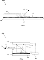
- FIG 1 illustrates an embodiment of the invention wherein the surface 102 of the substrate 101 is a reflective surface.
- a light source 104 is positioned to allow a light wave generated by the light source 104 to reach one or more cells 103 present at, e.g. on and in close contact with, the reflective surface 102, without any objects blocking its transmission path.
- the light wave reaches the cell 103 , diffraction of the light wave on the cell occurs, resulting in diffracted light.
- the diffracted light is reflected by the reflective surface 102 of the substrate 101.
- a part of the original light wave which does not diffract on the cell is also reflected by the reflective surface.
- the reflected diffracted light and the reflected original light wave interfere resulting in an optical signal.
- the optical signal is recorded by a sensor 105 which is positioned parallel or substantially parallel to the substrate 101 and adjacent to the surface at the side of the reflective surface 102, thereby allowing recording of the optical signal.
- the substrate 101 comprises a micro-electrode array which is used to record electrophysiological signals from cells 103 present on the surface 102 of the substrate 101.
- the micro-electrode array comprises a plurality of electrodes 106 , which may be implemented integrated in the surface 102 or positioned on the substrate surface 102 , for instance as pillars or rods. While illuminating cells 103 and recording optical signals caused by illumination of the cells 103 , electrophysiological signals of the cells can be recorded sim ultaneously.
- the lens-free device 100 comprises a beam-splitting device configured to direct a light wave generated by the light source towards cells 103 , when present on, e.g. in close contact with, the substrate surface 102.
- FIG 2 illustrates such an embodiment.
- the beam-splitting device 107 may be positioned in between the substrate 101 and the sensor 105.
- the substrate 101 and the sensor 105 are positioned parallel or substantially parallel to each other, wherein the sensing side of the sensor faces the reflective surface 102 of the substrate 101 on which cells 103 are held, provided or growing.
- the beam-splitting device 107 is positioned to redirect a light wave generated by the light source 104 onto cells 103 which are present on the surface 102 of the substrate 101.
- the beam-splitting device 107 may redirect the light wave emanating from the light source 104 , illustrated as arrow 109 , thereby achieving perpendicular or substantially perpendicular illumination of cells 103 present on the substrate surface 102.
- efficient detection of optical signals from cells with the image sensor 105 parallel or substantially parallel to the surface 102 may be achieved and compactness of the device may be increased.
- the beam-splitting device 107 is further configured to allow light waves reflected by the reflective surface 102 of the substrate 101 to transmit through the beam-splitting device 107 and to be received by the sensor 105 , illustrated as arrow 110.
- efficient illumination of cells 103 can be achieved.
- the substrate 101 comprises a micro-electrode array for recording electrophysiological signals from cells 103 present on the surface 102 of the substrate 101.
- the micro-electrode array may be as discussed above, for instance with respect to FIG 1 . While illuminating cells 103 and recording optical signals caused by illumination of the cells 103 , electrophysiological signals of the cells can be recorded simultaneously.
- the substrate 102 is fabricated from a transparent material, e.g. silicon oxide (glass) or a transparent polymer.
- the sensor 105 is positioned to record optical signals from cells present on the substrate surface 102.
- the sensor 105 and the light source 104 are provided at different sides of the substrate 101 , with the light source 104 being located at that side of the substrate 101 where the surface 102 is provided with electrodes 106 , and the sensor 105 being located at the side of the substrate 101 opposite thereto.
- the electrodes 106 (which may for instance be implemented as pillars, nanorods positioned on the substrate surface 102 or electrodes integrated in the substrate surface 102 ) of the MEA may be fabricated from a transparent conductive material which allows transmission of optical signals from cells.
- the electronic circuitry of the MEA may be positioned at one of the sides of the substrate to keep the electronic circuitry from blocking the transmission path of optical signals in the substrate.
- the substrate 101 comprising the MEA may be thinned, thereby allowing propagation of light through the substrate 101.
- FIG 3 illustrates such an embodiment.
- a sensor 105 is positioned substantially parallel with a substrate 101.
- a cell 103 is positioned on a surface 102 of the substrate 101.
- the substrate surface 102 faces away from the sensor 105.
- the sensing side of the sensor 105 faces the substrate 101.
- the substrate 101 comprises a micro-electrode array for sensing cells and optionally for actuating cells.
- a light source 104 is positioned to illuminate the substrate surface 102.
- the substrate 101 is fabricated from a transparent material that allows transmission of the light wave generated by the light source 104 and diffracted light from the illuminated cell 103. It is an advantage of embodiments of the invention that optical information of cells detected in transmission mode (through the substrate) provides enhanced image quality, comparable to image quality of traditional microscopy images. Also this embodiment allows to simultaneously detect optical and electrophysical signals from cells 103.
- the lens-free device 100 may furthermore comprise a processing unit 110 which is electrically connected to the sensor 105 and to the micro-electrode array comprising the plurality of electrodes 106.
- the processing unit 110 is configured to combine the detected optical signals from cells 103 and the electrophysiological signals of the cells 103.
- the processing unit 110 may be configured to correlate the detected optical signals from cells 103 and the electrophysiological signals of the cells 103.
- a goal of correlating the detected optical and electrophysical signals is to align the datasets, so that data relating to a same event on a cell, e.g. influence of a particular dose of a drug under particular circumstances including environmental circumstances like temperature, pH etc., can be taken into account.
- data relating to a same event on a cell e.g. influence of a particular dose of a drug under particular circumstances including environmental circumstances like temperature, pH etc.
- the effect of a candidate drug on the cells 103 under test can be more accurately determined.
- signals of similar cell events recorded at different moments in time are difficult to correlate due to e.g. manipulation of the cell under test or e.g. the difficulty in reproducing the same event in the cell, it is an advantage of embodiments of the invention that optical and electrophysiological signals of cells are obtained simultaneously.
- the senor 105 comprises a through-hole 108.
- the light source 104 is positioned to emit a light wave through the through-hole 108 , onto the substrate surface 102.
- the through hole is an aperture perforating the sensor 105 to allow a light wave to pass through the through-hole.
- the light source may be located inside the through-hole.
- the through-hole may be optically coupled to the light source for imparting a spatial coherence to the light wave generated by the light source.
- the through-hole may function as a pinhole for illuminating cells 103 with spatially coherent light.
- the sensor 105 can be placed close to and parallel to the substrate 101.
- FIG 4 illustrates such an embodiment.
- a sensor 105 and a substrate 101 are positioned substantially parallel to each other.
- the substrate surface 102 used for holding, growing or providing cells on faces the sensing side of the sensor 105.
- the sensor 105 comprises a through-hole 108.
- a light source 104 is positioned to generate a light wave through the through-hole 108 and to illuminate the surface 102 (and as a consequence also cells when present) of the substrate 101.
- the surface 102 of the substrate 101 which is used to hold, provide or grow cells on is a patterned surface adapted for mimicking in vivo organization through structured cell growth.
- the surface 102 may be patterned to induce a structured growth of cells 103 , for instance of cardiac cells.
- the grown cells may be made comparable to the structure of a human organ, for instance a human heart.
- the pattern may for instance comprise or consist of parallel lines, or any other suitable pattern as known in the art.
- a realistic measurement may be performed because the cells 103 on the substrate surface 102 are a realistic representation of the structure of the heart, including how it contracts and responds to external stimuli.
- the surface may comprise structures that control the growth of cells 103 on the surface 102.
- the structures may control the direction of growth of cells 103 on the surface 102. This may be achieved by providing structuring, e.g. grooves, in the substrate surface 102.
- the electrodes 106 implemented as protrusions, for instance pillars or nanorods, of the micro-electrode array are positioned and spaced from each other to induce a structured growth of cells 103 on the substrate surface 102.
- the electrodes 106 e.g. pillars, may be positioned in groups or in one or more rows spaced from each other to stimulate the cells 103 to grow in a specific direction.
- the substrate surface 102 may be provided, on selected areas, with a modification material for chemically or biologically modifying the surface so as to influence, e.g. allow or repel, growth of cells.
- This modification material may be applied, for instance, by printing.
- the printed surface comprises different areas or zones , selected to provide a particular pre-defined pattern, wherein each area or zone may be configured to differently influence, e.g. allow or repel, growth of cells.
- the different areas of the printed substrate surface may comprise a material, e.g. a biological material, that influences e.g. allows or repels, growth of cells.
- the conduction direction of cells can be controlled which simplifies post-processing of optical and electrophysiological signals and increases the relevance of the signals. It is an advantage of embodiments of the invention that software algorithms used for analysing signals from cells 103 may be simplified because conduction motion vectors of cells are more aligned. This is advantageous as simpler algorithms allow faster processing of data from cells.
- the conduction of contraction of cells 103 is perpendicular to the contraction direction of the cells.
- the motion vectors of cells under test and the conduction of contraction of cells can be controlled or predicted.
- the knowledge of how cells contract and in which direction contraction propagates simplifies the measuring of electrophysiological signals.
- FIG 5A and FIG 5B illustrate the difference in cell growth between a non-patterned surface ( FIG 5A ) and a patterned surface ( FIG 5B ).
- the arrow in FIG 5B indicates the direction of growth of cells on the substrate surface 102.
- the light source 104 is configured to generate different light waves, each light wave having a different wavelength range.
- the light source may be adapted to emit light waves with different wavelength ranges.
- the light source may consist of a single light emitting element capable of generating light waves in different wavelength ranges, or it may comprise a plurality of light emitting elements, each capable of generating light waves of at least one wavelength range, at least two light emitting elements of the plurality of light emitting elements being capable of generating light waves of different wavelength ranges.
- the sensor 105 may be adapted for detecting light waves with the different wavelength ranges.
- the sensor may be a multi-spectral or a hyperspectral image sensor configured to detect optical signals from cells with different wavelength ranges.
- cells 103 under test may be illuminated using light waves with different wavelength ranges to determine information of different parts of the cell.
- the optical signals from illuminated cells with different wavelength ranges can be used to analyse the effect of a drug on a specific part of the cell under test, e.g. the part of the cell responsible for contraction.
- a more accurate and better drug screening can be done.
- using light waves with different wavelength ranges may be used to retrieve phase information which can be used to solve the twin image problem occurring in lens-free imaging applications. By doing so, image quality can be increased resulting in a more accurate drug screening.
- the device comprises a fluidic system fluidically coupled to the surface 102 of the substrate 101 for administering a candidate drug to cells 103 , when present, on the substrate surface 102.
- the fluidic system may have an inlet and an outlet for providing and exiting a solution comprising the candidate drug.
- the substrate comprises a fluidics system 111 , e.g. a fluidics or micro-fluidics layer embedded in or on the substrate, which is adapted to provide a candidate drug to one or more locations of the substrate surface for contacting cells when present on that surface with the candidate drug.
- a fluidics system 111 is illustrated, as an example only, in the embodiment of FIG 3 , but this is not intended to be limiting for the present invention.
- a fluidics system may be used in any lens free device 100 according to embodiments of the present invention, for instance, but not limited thereto, the devices 100 as described with respect to FIG 1 to FIG 4 .
- the fluidics system 111 may be a conventional fluidics system, such as for instance one or more microfluidic channels provided in a microfluidic substrate, such as a transparent microfluidic substrate, such as for instance a glass substrate or a PDMS (polydimethylsiloxaan) substrate.
- a microfluidic substrate such as a transparent microfluidic substrate, such as for instance a glass substrate or a PDMS (polydimethylsiloxaan) substrate.
- Such fluidics system 111 may be provided on top of the substrate surface 102 such that cells 103 may be provided inside the one or more microfluidics channels.
- the microfluidic channels may be filled with fluid, also called the cell medium.
- the fluid may contain required elements to keep the cells 103 in good health.
- the fluid in the one or more microfluidic channels may be static (no flow) or dynamic (flow).
- cells 103 may be conducted by the flow, towards and away from detections sites where optical and electrophysical signals are detected. It is an advantage of embodiments of the present invention that lens free imaging in presence of a fluidics system 111 works.
- the transparent microfluidics substrate like a glass substrate or a PDMS substrate, proves not to influence the optical measurement results.
- the fluidics system 111 is adapted to provide different candidate drugs to different locations of the substrate surface 102 for contacting different cells 103 , when present on the substrate surface 102 , with a different candidate drug.
- the fluidics system 111 may comprise a plurality of fluidic channels, valves and pumps, embedded in the substrate, and configured for distributing different candidate drugs to different locations of the substrate surface.
- the valves and pumps which might obstruct the optical path of the light wave for illuminating the cells 103 or the optical signal caused by the illumination of the cells 103 , may be positioned outside the area used for imaging.
- the substrate surface 102 comprises a plurality of wells suitable for providing, holding or growing cells on, each well being fluidically connected to a fluidic channel of the fluidic system 111 .
- Each well may be used to analyse the effects of a different drug on the cells 103 in that well. It is an advantage of embodiments of the invention that all wells on the substrate surface 102 may be analysed simultaneously as 1) the lens-free imaging capability of the device 100 provides a large field of view and as 2) electrophysiological signals of cells 103 may be sensed and recorded simultaneously. As an advantage, different experiments with different candidate drugs may be performed at the same time. This increases the throughput of the system and reduces the time to perform the drug screening.
- the cells under test are biological cells.
- the cells are cardiac cells, neurons or any other adherent cell.
- the invention is particularly advantageous for cardiac cells as simultaneous detection of electrophysiological signals and cardiac contraction is possible, thereby allowing a correlation on different types of signals from cells to be performed. As an advantage, a more accurate and better drug screening can be done.
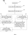
- a method 600 for performing drug screening on cells 103 is presented.
- the method 600 is also suitable for assessing the electromechanical window of the cells 103 such as for instance, but not limited thereto, cardiac cells.
- the method 600 comprises the steps of providing 601 the cells and contacting 602 the cells 103 with a candidate drug, e.g. by providing a solution comprising the candidate drug on the cells 103.
- the cells 103 are illuminated 603 with a light wave, for instance emanating from a light source 104.
- the light wave diffracts on the cells 103 giving rise to diffracted light.
- the diffracted light interferes with the original light wave resulting in an optical signal which is detected 604 and recorded.
- electrophysiological signals of the cells are detected 605 and recorded in parallel.
- a correlation 606 between the optical signal and the electrophysiological signal may be performed to determine the influence of the candidate drug on the cells 103. This is illustrated in the flowchart of FIG 6 .
- the method may be implemented using a device 100 as described in any of the embodiments of the first aspect of the invention wherein 1) cells 103 are provided 601 on the substrate surface 102 , 2) the cells 103 on the substrate surface 102 are illuminated 603 using the light source 104 and wherein 3) an optical signal and electrophysiological signals of cells are simultaneously detected 604 , 605 by the sensor 105 and the micro-electrode array, respectively.
- the method may further comprise reconstructing 607 an image representation of the cells 103 using the recorded optical signal.
- the reconstructed image representation may provide extra information on e.g. the morphology of the cells 103. From the reconstructed image representation more information can be extracted on e.g. the viability status of the cell. This is advantageous as it provides a direct way of checking the viability status of the cell 103 , compared to prior art techniques which use indirect ways to check the viability status, e.g. by checking the level of an analyte in a cell.
- the reconstructed image representation may be correlated with the recorded electrophysiological signal.
- the reconstructed image representation may be used to extract different parameters from a cell 103 wherein each parameter may be correlated with the recorded electrophysiological signal of that cell.
- cardiac contraction parameters may be extracted such as contraction frequency, contraction strength, signal propagation through the tissue, duration of the contraction.
- Each parameter may be related to a specific electrophysiological signal. It is an advantage of embodiments of the invention that images with a quality comparable to microscopy images may be retrieved without sacrificing the large field of view.
- light waves with different wavelength ranges are used to illuminate the cells 103 sequentially. This is illustrated in the flowchart 700 of FIG 7 .
- cells are illuminated 603 with a light wave with a specific wavelength range
- optical and electrophysiological signals are detected 604 , 605 and recorded and the signals are correlated 606.
- the wavelength range of the light wave used to illuminate the cells is changed 701 ; such that in different sequences, cells are illuminated with a light wave with a different wavelength range, optical and electrophysiological signals are detected and recorded and the signals are correlated.
- the different datasets (optical signal + electrophysiological signal) for each wavelength range may be correlated to determine influence of the candidate drug on the cells 103.
- using light waves with different wavelength ranges may also reveal specific information on the structure of the cell 103 , e.g. different parts of the cell.
- the method further comprises counting the cells using the correlated signals.
- the simultaneous recording of optical signals and electrophysiological signals from cells and the correlation of both type of signals can be used to perform a counting of cells. It is an advantage of embodiments of the invention that by correlating, increased accuracy of the counting can be achieved. As a further advantage, as simultaneous detection of optical and electrophysiological signals is possible, time needed to perform the counting can be reduced.
- the method for performing drug screening may further comprise actuating the cell 103 for inducing an event in the cell.
- the cell may be actuated to induce a contraction.
- the actuating may be performed while detecting and recording optical and electrophysiological signals.
- the electrodes 106 of the microelectrode array may be used for actuating the cells 103.
- the invention was evaluated for the visualization of cardiac cells on a micro-structured reflective surface 102.
- the setup used in the experiments consisted of a beam splitter 107 placed between a sensor 105 and a sample 103, and a laser 104 which illuminated the setup from the side (such as illustrated in FIG 2 ).
- the coherent light from the light source 104 was directed onto the sample surface 102 through the beam splitter 107 and the incoming light was substantially perpendicular to the sample 103.
- the reflected light was then recorded by the sensor 105 and was further analysed by focusing through reconstruction or by the detection of contractions.
- Samples were initially measured in dry conditions as well as under refractive index matching liquid and cell culture medium. Samples consisted of either silicon samples containing pattern samples with ridges consisting of 800 nm width, 500 nm height and 1600 nm spacing or MEA arrays. These samples were plated with cardiac cells extracted from 2 day old neonatal rats.
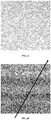
- Patterned silicon oxide substrates were visualized through reflective lens free imaging at a rate of 100 frames per second and the obtained holograms showed that the field-of-view was limited by the size of the beam splitters 107 and enclosed by interference fringes from the beam splitter edges. If the patterned substrate was visualized in air, a complex pattern of multiple reflections was detected ( FIG 8A ) which was not present if the sample was measured in a refractive index matching liquid ( FIG 8B ). Furthermore, low density of fixated cells was detected directly on the hologram ( FIG 8B ), which was confirmed by reconstruction ( FIG 8C ). The complex pattern of multiple reflections was also not detected in samples containing monolayers of cardiac cells ( FIG 9A ) and spontaneous contractions of clusters of cells were detectable after further processing ( FIG 9B ).
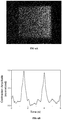
- the imaging system detected the contraction of cardiac cells of a substrate consisting of a MEA array.
- the MEA chip was plated with a monolayer of postnatal cardiomyocytes and the obtained holograms showed more complex interference fringes as a result of the MEA topography ( FIG 10A ). Nevertheless, the beating of cardiac cells could be measured ( FIG 10B ) and the required laser intensities did not influence simultaneous electrophysiological measurements.
Applications Claiming Priority (2)
| Application Number | Priority Date | Filing Date | Title |
|---|---|---|---|
| EP14163422 | 2014-04-03 | ||
| PCT/EP2015/097017 WO2015150589A1 (en) | 2014-04-03 | 2015-04-03 | Method and device for drug screening |
Publications (2)
| Publication Number | Publication Date |
|---|---|
| EP3126818A1 EP3126818A1 (en) | 2017-02-08 |
| EP3126818B1 true EP3126818B1 (en) | 2018-12-05 |
Family
ID=50397061
Family Applications (1)
| Application Number | Title | Priority Date | Filing Date |
|---|---|---|---|
| EP15713796.9A Active EP3126818B1 (en) | 2014-04-03 | 2015-04-03 | Method and device for drug screening |
Country Status (4)
| Country | Link |
|---|---|
| US (1) | US10697882B2 (ja) |
| EP (1) | EP3126818B1 (ja) |
| JP (1) | JP6446059B2 (ja) |
| WO (1) | WO2015150589A1 (ja) |
Families Citing this family (6)
| Publication number | Priority date | Publication date | Assignee | Title |
|---|---|---|---|---|
| JP2017146696A (ja) | 2016-02-16 | 2017-08-24 | ソニー株式会社 | 画像処理装置、画像処理方法及び画像処理システム |
| WO2018064660A1 (en) * | 2016-09-30 | 2018-04-05 | University Of Utah Research Foundation | Lensless imaging device |
| EP3502695A1 (en) * | 2017-12-22 | 2019-06-26 | IMEC vzw | A method and a system for analysis of cardiomyocyte function |
| KR102144523B1 (ko) * | 2018-11-26 | 2020-08-13 | (주) 솔 | 일체화된 카트리지 |
| WO2020022713A1 (ko) * | 2018-07-26 | 2020-01-30 | (주) 솔 | 측면광을 활용한 이미지 센서 기반의 바이오 진단 장치 및 일체화된 카트리지 |
| KR102088364B1 (ko) * | 2018-07-26 | 2020-03-12 | (주) 솔 | 측면광을 활용한 이미지 센서 기반의 바이오 진단 장치 |
Family Cites Families (11)
| Publication number | Priority date | Publication date | Assignee | Title |
|---|---|---|---|---|
| US7160687B1 (en) * | 1997-05-29 | 2007-01-09 | Cellomics, Inc. | Miniaturized cell array methods and apparatus for cell-based screening |
| EP1141251A4 (en) * | 1998-12-23 | 2004-09-22 | Cytoscan Sciences Llc | COMPOSITIONS, SCREENING TECHNIQUES AND METHODS FOR TREATING DISORDERS OF THE CENTRAL AND PERIPHERAL NERVOUS SYSTEMS |
| US6686193B2 (en) * | 2000-07-10 | 2004-02-03 | Vertex Pharmaceuticals, Inc. | High throughput method and system for screening candidate compounds for activity against target ion channels |
| JP4814875B2 (ja) * | 2004-05-11 | 2011-11-16 | アキシオジェネシス エージー | invitro分化細胞に基づく薬物発見のための検定 |
| CN101711276B (zh) * | 2007-06-08 | 2014-05-07 | 国立大学法人东京医科齿科大学 | 模型细胞芯片,利用模型细胞芯片的药效评价装置以及药效评价方法 |
| WO2010148252A1 (en) * | 2009-06-17 | 2010-12-23 | Jody Vykoukal | Method and apparatus for quantitative microimaging |
| US20110231103A1 (en) * | 2010-03-19 | 2011-09-22 | Ye Fang | Methods for determining molecular pharmacology using label-free integrative pharmacology |
| EP2657792B1 (en) * | 2012-04-24 | 2017-11-15 | Imec | Device and method for holographic reflection imaging |
| EP2657793B1 (en) * | 2012-04-24 | 2017-10-18 | Imec | Device and method for holographic reflection imaging |
| EP3040750A1 (en) | 2014-12-29 | 2016-07-06 | IMEC vzw | Device and method for performing lens-free imaging |
| WO2016124677A1 (en) | 2015-02-06 | 2016-08-11 | Imec Vzw | Large area lens-free imaging device |
-
2015
- 2015-04-03 US US15/129,267 patent/US10697882B2/en active Active
- 2015-04-03 WO PCT/EP2015/097017 patent/WO2015150589A1/en active Application Filing
- 2015-04-03 JP JP2016560373A patent/JP6446059B2/ja not_active Expired - Fee Related
- 2015-04-03 EP EP15713796.9A patent/EP3126818B1/en active Active
Non-Patent Citations (1)
| Title |
|---|
| None * |
Also Published As
| Publication number | Publication date |
|---|---|
| US10697882B2 (en) | 2020-06-30 |
| JP6446059B2 (ja) | 2018-12-26 |
| JP2017511477A (ja) | 2017-04-20 |
| WO2015150589A1 (en) | 2015-10-08 |
| US20170115201A1 (en) | 2017-04-27 |
| EP3126818A1 (en) | 2017-02-08 |
Similar Documents
| Publication | Publication Date | Title |
|---|---|---|
| EP3126818B1 (en) | Method and device for drug screening | |
| US20160327776A1 (en) | Apparatus and method for quantitative phase-gradient chirped-wavelength-encoded optical imaging | |
| FR2872583A1 (fr) | Transducteur ultrasonore avec capteurs supplementaires | |
| EP3615921A2 (en) | Orthogonal polybiosensing and imaging systems | |
| Chan et al. | Label-free imaging of cancer cells using photonic crystal biosensors and application to cytotoxicity screening of a natural compound library | |
| US20220133273A1 (en) | Transparent ultrasound transducers for photoacoustic imaging | |
| JP2023519337A (ja) | 生物学的サンプルを電子的および光学的に監視するためのシステムおよび方法 | |
| Li et al. | An approach for cell viability online detection based on the characteristics of lensfree cell diffraction fingerprint | |
| US20210396783A1 (en) | Array atomic force microscopy for enabling simultaneous multi-point and multi-modal nanoscale analyses and stimulations | |
| EP1421380B1 (de) | Vorrichtung und verfahren zur erfassung bioelektrischer signale aus elektrophysiologisch aktiven bereichen in sphäroiden | |
| JP6296606B2 (ja) | 硬膜下センサ | |
| US20220250056A1 (en) | Orthogonal polybiosensing and imaging systems | |
| EP3460585B1 (en) | An imaging device for in-line holographic imaging of an object | |
| CA2987765C (en) | A tunable neuronal network and an artificial eye | |
| Kang et al. | Quantitative reflection imaging for the morphology and dynamics of live Aplysia californica pedal ganglion neurons cultured on nanostructured plasmonic crystals | |
| US11971353B2 (en) | Multiplexed surface plasmon resonance sensing of analytes in liquid sample | |
| US20240159733A1 (en) | Tunable neuronal network and an artificial eye | |
| Tan et al. | Massively Concurrent Sub-Cellular Traction Force Videography enabled by Single-Pixel Optical Tracers (SPOTs) | |
| Dorizan et al. | A novel stimulator to investigate the tuning of multi-whisker responsive neurons for speed and the direction of global motion: Contact-sensitive moving stimulator for multi-whisker stimulation | |
| Singh | Integrated bio-photonic devices: sensors, imagers, and beyond | |
| Emiliani et al. | High-throughput in vivo synaptic connectivity mapping of neuronal micro-circuits using two-photon holographic optogenetics and compressive sensing | |
| Reddy | High-density Flexible Neurophotonic Implants | |
| GB2615370A (en) | Detection using SERS probes | |
| Graf et al. | Detecting action-potential-correlated scattering changes in single neurons | |
| Byrd et al. | Design of a cylindrical fiber-optic lens focusing passive dual-color IR spectra and readout |
Legal Events
| Date | Code | Title | Description |
|---|---|---|---|
| STAA | Information on the status of an ep patent application or granted ep patent |
Free format text: STATUS: THE INTERNATIONAL PUBLICATION HAS BEEN MADE |
|
| PUAI | Public reference made under article 153(3) epc to a published international application that has entered the european phase |
Free format text: ORIGINAL CODE: 0009012 |
|
| STAA | Information on the status of an ep patent application or granted ep patent |
Free format text: STATUS: REQUEST FOR EXAMINATION WAS MADE |
|
| 17P | Request for examination filed |
Effective date: 20161028 |
|
| AK | Designated contracting states |
Kind code of ref document: A1 Designated state(s): AL AT BE BG CH CY CZ DE DK EE ES FI FR GB GR HR HU IE IS IT LI LT LU LV MC MK MT NL NO PL PT RO RS SE SI SK SM TR |
|
| AX | Request for extension of the european patent |
Extension state: BA ME |
|
| DAV | Request for validation of the european patent (deleted) | ||
| DAX | Request for extension of the european patent (deleted) | ||
| GRAP | Despatch of communication of intention to grant a patent |
Free format text: ORIGINAL CODE: EPIDOSNIGR1 |
|
| STAA | Information on the status of an ep patent application or granted ep patent |
Free format text: STATUS: GRANT OF PATENT IS INTENDED |
|
| RIC1 | Information provided on ipc code assigned before grant |
Ipc: G01N 33/50 20060101ALI20180625BHEP Ipc: G01N 21/17 20060101ALI20180625BHEP Ipc: G01N 15/00 20060101ALI20180625BHEP Ipc: G03H 1/26 20060101ALI20180625BHEP Ipc: G01N 21/45 20060101AFI20180625BHEP Ipc: G03H 1/04 20060101ALI20180625BHEP Ipc: G01N 21/47 20060101ALI20180625BHEP Ipc: G01N 15/14 20060101ALI20180625BHEP Ipc: G03H 1/00 20060101ALI20180625BHEP Ipc: G01N 15/10 20060101ALI20180625BHEP |
|
| INTG | Intention to grant announced |
Effective date: 20180716 |
|
| GRAS | Grant fee paid |
Free format text: ORIGINAL CODE: EPIDOSNIGR3 |
|
| GRAA | (expected) grant |
Free format text: ORIGINAL CODE: 0009210 |
|
| STAA | Information on the status of an ep patent application or granted ep patent |
Free format text: STATUS: THE PATENT HAS BEEN GRANTED |
|
| AK | Designated contracting states |
Kind code of ref document: B1 Designated state(s): AL AT BE BG CH CY CZ DE DK EE ES FI FR GB GR HR HU IE IS IT LI LT LU LV MC MK MT NL NO PL PT RO RS SE SI SK SM TR |
|
| REG | Reference to a national code |
Ref country code: GB Ref legal event code: FG4D |
|
| REG | Reference to a national code |
Ref country code: CH Ref legal event code: EP |
|
| REG | Reference to a national code |
Ref country code: AT Ref legal event code: REF Ref document number: 1073678 Country of ref document: AT Kind code of ref document: T Effective date: 20181215 |
|
| REG | Reference to a national code |
Ref country code: IE Ref legal event code: FG4D |
|
| REG | Reference to a national code |
Ref country code: DE Ref legal event code: R096 Ref document number: 602015020847 Country of ref document: DE |
|
| REG | Reference to a national code |
Ref country code: NL Ref legal event code: MP Effective date: 20181205 |
|
| REG | Reference to a national code |
Ref country code: AT Ref legal event code: MK05 Ref document number: 1073678 Country of ref document: AT Kind code of ref document: T Effective date: 20181205 |
|
| REG | Reference to a national code |
Ref country code: LT Ref legal event code: MG4D |
|
| PG25 | Lapsed in a contracting state [announced via postgrant information from national office to epo] |
Ref country code: ES Free format text: LAPSE BECAUSE OF FAILURE TO SUBMIT A TRANSLATION OF THE DESCRIPTION OR TO PAY THE FEE WITHIN THE PRESCRIBED TIME-LIMIT Effective date: 20181205 Ref country code: BG Free format text: LAPSE BECAUSE OF FAILURE TO SUBMIT A TRANSLATION OF THE DESCRIPTION OR TO PAY THE FEE WITHIN THE PRESCRIBED TIME-LIMIT Effective date: 20190305 Ref country code: HR Free format text: LAPSE BECAUSE OF FAILURE TO SUBMIT A TRANSLATION OF THE DESCRIPTION OR TO PAY THE FEE WITHIN THE PRESCRIBED TIME-LIMIT Effective date: 20181205 Ref country code: LV Free format text: LAPSE BECAUSE OF FAILURE TO SUBMIT A TRANSLATION OF THE DESCRIPTION OR TO PAY THE FEE WITHIN THE PRESCRIBED TIME-LIMIT Effective date: 20181205 Ref country code: NO Free format text: LAPSE BECAUSE OF FAILURE TO SUBMIT A TRANSLATION OF THE DESCRIPTION OR TO PAY THE FEE WITHIN THE PRESCRIBED TIME-LIMIT Effective date: 20190305 Ref country code: LT Free format text: LAPSE BECAUSE OF FAILURE TO SUBMIT A TRANSLATION OF THE DESCRIPTION OR TO PAY THE FEE WITHIN THE PRESCRIBED TIME-LIMIT Effective date: 20181205 Ref country code: FI Free format text: LAPSE BECAUSE OF FAILURE TO SUBMIT A TRANSLATION OF THE DESCRIPTION OR TO PAY THE FEE WITHIN THE PRESCRIBED TIME-LIMIT Effective date: 20181205 Ref country code: AT Free format text: LAPSE BECAUSE OF FAILURE TO SUBMIT A TRANSLATION OF THE DESCRIPTION OR TO PAY THE FEE WITHIN THE PRESCRIBED TIME-LIMIT Effective date: 20181205 |
|
| PG25 | Lapsed in a contracting state [announced via postgrant information from national office to epo] |
Ref country code: AL Free format text: LAPSE BECAUSE OF FAILURE TO SUBMIT A TRANSLATION OF THE DESCRIPTION OR TO PAY THE FEE WITHIN THE PRESCRIBED TIME-LIMIT Effective date: 20181205 Ref country code: SE Free format text: LAPSE BECAUSE OF FAILURE TO SUBMIT A TRANSLATION OF THE DESCRIPTION OR TO PAY THE FEE WITHIN THE PRESCRIBED TIME-LIMIT Effective date: 20181205 Ref country code: RS Free format text: LAPSE BECAUSE OF FAILURE TO SUBMIT A TRANSLATION OF THE DESCRIPTION OR TO PAY THE FEE WITHIN THE PRESCRIBED TIME-LIMIT Effective date: 20181205 Ref country code: GR Free format text: LAPSE BECAUSE OF FAILURE TO SUBMIT A TRANSLATION OF THE DESCRIPTION OR TO PAY THE FEE WITHIN THE PRESCRIBED TIME-LIMIT Effective date: 20190306 |
|
| PG25 | Lapsed in a contracting state [announced via postgrant information from national office to epo] |
Ref country code: NL Free format text: LAPSE BECAUSE OF FAILURE TO SUBMIT A TRANSLATION OF THE DESCRIPTION OR TO PAY THE FEE WITHIN THE PRESCRIBED TIME-LIMIT Effective date: 20181205 |
|
| PG25 | Lapsed in a contracting state [announced via postgrant information from national office to epo] |
Ref country code: PT Free format text: LAPSE BECAUSE OF FAILURE TO SUBMIT A TRANSLATION OF THE DESCRIPTION OR TO PAY THE FEE WITHIN THE PRESCRIBED TIME-LIMIT Effective date: 20190405 Ref country code: CZ Free format text: LAPSE BECAUSE OF FAILURE TO SUBMIT A TRANSLATION OF THE DESCRIPTION OR TO PAY THE FEE WITHIN THE PRESCRIBED TIME-LIMIT Effective date: 20181205 Ref country code: IT Free format text: LAPSE BECAUSE OF FAILURE TO SUBMIT A TRANSLATION OF THE DESCRIPTION OR TO PAY THE FEE WITHIN THE PRESCRIBED TIME-LIMIT Effective date: 20181205 Ref country code: PL Free format text: LAPSE BECAUSE OF FAILURE TO SUBMIT A TRANSLATION OF THE DESCRIPTION OR TO PAY THE FEE WITHIN THE PRESCRIBED TIME-LIMIT Effective date: 20181205 |
|
| PG25 | Lapsed in a contracting state [announced via postgrant information from national office to epo] |
Ref country code: EE Free format text: LAPSE BECAUSE OF FAILURE TO SUBMIT A TRANSLATION OF THE DESCRIPTION OR TO PAY THE FEE WITHIN THE PRESCRIBED TIME-LIMIT Effective date: 20181205 Ref country code: SM Free format text: LAPSE BECAUSE OF FAILURE TO SUBMIT A TRANSLATION OF THE DESCRIPTION OR TO PAY THE FEE WITHIN THE PRESCRIBED TIME-LIMIT Effective date: 20181205 Ref country code: SK Free format text: LAPSE BECAUSE OF FAILURE TO SUBMIT A TRANSLATION OF THE DESCRIPTION OR TO PAY THE FEE WITHIN THE PRESCRIBED TIME-LIMIT Effective date: 20181205 Ref country code: IS Free format text: LAPSE BECAUSE OF FAILURE TO SUBMIT A TRANSLATION OF THE DESCRIPTION OR TO PAY THE FEE WITHIN THE PRESCRIBED TIME-LIMIT Effective date: 20190405 Ref country code: RO Free format text: LAPSE BECAUSE OF FAILURE TO SUBMIT A TRANSLATION OF THE DESCRIPTION OR TO PAY THE FEE WITHIN THE PRESCRIBED TIME-LIMIT Effective date: 20181205 |
|
| REG | Reference to a national code |
Ref country code: DE Ref legal event code: R097 Ref document number: 602015020847 Country of ref document: DE |
|
| PLBE | No opposition filed within time limit |
Free format text: ORIGINAL CODE: 0009261 |
|
| STAA | Information on the status of an ep patent application or granted ep patent |
Free format text: STATUS: NO OPPOSITION FILED WITHIN TIME LIMIT |
|
| PG25 | Lapsed in a contracting state [announced via postgrant information from national office to epo] |
Ref country code: SI Free format text: LAPSE BECAUSE OF FAILURE TO SUBMIT A TRANSLATION OF THE DESCRIPTION OR TO PAY THE FEE WITHIN THE PRESCRIBED TIME-LIMIT Effective date: 20181205 Ref country code: DK Free format text: LAPSE BECAUSE OF FAILURE TO SUBMIT A TRANSLATION OF THE DESCRIPTION OR TO PAY THE FEE WITHIN THE PRESCRIBED TIME-LIMIT Effective date: 20181205 |
|
| 26N | No opposition filed |
Effective date: 20190906 |
|
| REG | Reference to a national code |
Ref country code: CH Ref legal event code: PL |
|
| REG | Reference to a national code |
Ref country code: BE Ref legal event code: MM Effective date: 20190430 |
|
| PG25 | Lapsed in a contracting state [announced via postgrant information from national office to epo] |
Ref country code: LU Free format text: LAPSE BECAUSE OF NON-PAYMENT OF DUE FEES Effective date: 20190403 Ref country code: MC Free format text: LAPSE BECAUSE OF FAILURE TO SUBMIT A TRANSLATION OF THE DESCRIPTION OR TO PAY THE FEE WITHIN THE PRESCRIBED TIME-LIMIT Effective date: 20181205 |
|
| PG25 | Lapsed in a contracting state [announced via postgrant information from national office to epo] |
Ref country code: CH Free format text: LAPSE BECAUSE OF NON-PAYMENT OF DUE FEES Effective date: 20190430 Ref country code: LI Free format text: LAPSE BECAUSE OF NON-PAYMENT OF DUE FEES Effective date: 20190430 |
|
| PG25 | Lapsed in a contracting state [announced via postgrant information from national office to epo] |
Ref country code: BE Free format text: LAPSE BECAUSE OF NON-PAYMENT OF DUE FEES Effective date: 20190430 |
|
| PG25 | Lapsed in a contracting state [announced via postgrant information from national office to epo] |
Ref country code: TR Free format text: LAPSE BECAUSE OF FAILURE TO SUBMIT A TRANSLATION OF THE DESCRIPTION OR TO PAY THE FEE WITHIN THE PRESCRIBED TIME-LIMIT Effective date: 20181205 |
|
| PG25 | Lapsed in a contracting state [announced via postgrant information from national office to epo] |
Ref country code: IE Free format text: LAPSE BECAUSE OF NON-PAYMENT OF DUE FEES Effective date: 20190403 |
|
| PG25 | Lapsed in a contracting state [announced via postgrant information from national office to epo] |
Ref country code: CY Free format text: LAPSE BECAUSE OF FAILURE TO SUBMIT A TRANSLATION OF THE DESCRIPTION OR TO PAY THE FEE WITHIN THE PRESCRIBED TIME-LIMIT Effective date: 20181205 |
|
| PGFP | Annual fee paid to national office [announced via postgrant information from national office to epo] |
Ref country code: GB Payment date: 20210324 Year of fee payment: 7 |
|
| PG25 | Lapsed in a contracting state [announced via postgrant information from national office to epo] |
Ref country code: HU Free format text: LAPSE BECAUSE OF FAILURE TO SUBMIT A TRANSLATION OF THE DESCRIPTION OR TO PAY THE FEE WITHIN THE PRESCRIBED TIME-LIMIT; INVALID AB INITIO Effective date: 20150403 Ref country code: MT Free format text: LAPSE BECAUSE OF FAILURE TO SUBMIT A TRANSLATION OF THE DESCRIPTION OR TO PAY THE FEE WITHIN THE PRESCRIBED TIME-LIMIT Effective date: 20181205 |
|
| PG25 | Lapsed in a contracting state [announced via postgrant information from national office to epo] |
Ref country code: MK Free format text: LAPSE BECAUSE OF FAILURE TO SUBMIT A TRANSLATION OF THE DESCRIPTION OR TO PAY THE FEE WITHIN THE PRESCRIBED TIME-LIMIT Effective date: 20181205 |
|
| GBPC | Gb: european patent ceased through non-payment of renewal fee |
Effective date: 20220403 |
|
| PG25 | Lapsed in a contracting state [announced via postgrant information from national office to epo] |
Ref country code: GB Free format text: LAPSE BECAUSE OF NON-PAYMENT OF DUE FEES Effective date: 20220403 |
|
| PGFP | Annual fee paid to national office [announced via postgrant information from national office to epo] |
Ref country code: FR Payment date: 20230321 Year of fee payment: 9 |
|
| P01 | Opt-out of the competence of the unified patent court (upc) registered |
Effective date: 20230513 |
|
| PGFP | Annual fee paid to national office [announced via postgrant information from national office to epo] |
Ref country code: DE Payment date: 20230321 Year of fee payment: 9 |