EP3126738B1 - Gas burner for a cooking hob and cooking hob comprising such a gas burner - Google Patents
Gas burner for a cooking hob and cooking hob comprising such a gas burner Download PDFInfo
- Publication number
- EP3126738B1 EP3126738B1 EP15718096.9A EP15718096A EP3126738B1 EP 3126738 B1 EP3126738 B1 EP 3126738B1 EP 15718096 A EP15718096 A EP 15718096A EP 3126738 B1 EP3126738 B1 EP 3126738B1
- Authority
- EP
- European Patent Office
- Prior art keywords
- gas burner
- air
- inlet
- ring nut
- gas mixture
- Prior art date
- Legal status (The legal status is an assumption and is not a legal conclusion. Google has not performed a legal analysis and makes no representation as to the accuracy of the status listed.)
- Active
Links
- 238000010411 cooking Methods 0.000 title claims description 32
- 239000000203 mixture Substances 0.000 claims description 41
- 239000012530 fluid Substances 0.000 claims description 4
- 238000005192 partition Methods 0.000 claims description 4
- 230000000284 resting effect Effects 0.000 claims 1
- 230000000994 depressogenic effect Effects 0.000 description 2
- 238000010438 heat treatment Methods 0.000 description 2
- 230000004888 barrier function Effects 0.000 description 1
- 230000000694 effects Effects 0.000 description 1
- 230000014509 gene expression Effects 0.000 description 1
Images


Classifications
-
- F—MECHANICAL ENGINEERING; LIGHTING; HEATING; WEAPONS; BLASTING
- F23—COMBUSTION APPARATUS; COMBUSTION PROCESSES
- F23D—BURNERS
- F23D14/00—Burners for combustion of a gas, e.g. of a gas stored under pressure as a liquid
- F23D14/46—Details, e.g. noise reduction means
- F23D14/48—Nozzles
- F23D14/58—Nozzles characterised by the shape or arrangement of the outlet or outlets from the nozzle, e.g. of annular configuration
- F23D14/583—Nozzles characterised by the shape or arrangement of the outlet or outlets from the nozzle, e.g. of annular configuration of elongated shape, e.g. slits
-
- F—MECHANICAL ENGINEERING; LIGHTING; HEATING; WEAPONS; BLASTING
- F23—COMBUSTION APPARATUS; COMBUSTION PROCESSES
- F23D—BURNERS
- F23D14/00—Burners for combustion of a gas, e.g. of a gas stored under pressure as a liquid
- F23D14/02—Premix gas burners, i.e. in which gaseous fuel is mixed with combustion air upstream of the combustion zone
- F23D14/04—Premix gas burners, i.e. in which gaseous fuel is mixed with combustion air upstream of the combustion zone induction type, e.g. Bunsen burner
- F23D14/08—Premix gas burners, i.e. in which gaseous fuel is mixed with combustion air upstream of the combustion zone induction type, e.g. Bunsen burner with axial outlets at the burner head
- F23D14/085—Premix gas burners, i.e. in which gaseous fuel is mixed with combustion air upstream of the combustion zone induction type, e.g. Bunsen burner with axial outlets at the burner head with injector axis inclined to the burner head axis
Definitions
- the present invention relates to a gas burner for a cooking hob.
- the gas burner of the invention is of the depressed type, i.e., it is configured to be associated with the cooking hob so that the upper surface thereof is positioned substantially at the same level as the cooking hob or projects in an absolutely insignificant manner with respect to the cooking hob taking as a reference the overall height of the gas burner.
- the gas burner of the invention is of the laminar type.
- a gas burner of the laminar flame type is known by the Italian patent application n° MI2011A001471 to the same Applicant.
- Such a burner comprises, in the essential elements thereof, a hollow structure in which an annular expansion chamber for the expansion of the air/gas mixture (such a mixture comprising primary air) and, at the top of said annular expansion chamber, an elongated annular slot for the outlet of the air/gas mixture are defined.
- the gas burner with a laminar flame described above is capable of increasing the yield with respect to conventional gas burners of the type described for example in EP 1 469 256 .
- Such gas burners comprise a plurality of openings for the outlet of the air/gas mixture from the expansion chamber, wherein such outlet openings are closer together and have a different diameter from one another so as to supply air/gas mixture to pilot flames that are alternated with heating flames.
- the alternation of pilot flames with heating flames is a configuration that has limitations also as far as the modulation capability of the gas burner is concerned, and moreover it does not make it possible to drop below set power values.
- the outlet openings have small dimensions and therefore they can easily become obstructed and can make it difficult for the flame to propagate to the adjacent outlet openings during ignition of the gas burner.
- the gas burner with a laminar flame is capable of reaching very low minimum values.
- the elongated annular slot ensures that the flame propagates well along the entire length of the slot during ignition, avoiding the drawbacks of conventional gas burners.
- the gas burner with laminar flame has a good aesthetic appearance, essentially due to the absence of a plurality of outlet openings and, when turned on, to the provision of a vertical flame having the shape of a continuous ring.
- a gas burner with a laminar flame is also known from GB 1 544 624 A .
- the gas burner with a laminar flame of the type known in Italian patent application n° MI2011A001471 is configured so that, when it is mounted on a cooking hob, the annular expansion chamber projects in a considerable manner above the cooking hob.
- the Applicant has felt the need to improve the aesthetic appearance of the gas burner with laminar flame described above.
- the Applicant has thought of making a gas burner with depressed laminar flame, i.e. configured so as to project above the cooking hob in an absolutely insignificant manner.
- the present invention thus relates, in a first aspect thereof, to a gas burner for a cooking hob, comprising at least one hollow structure in which an inlet chamber for the inlet of an air/gas mixture, an expansion chamber for the expansion of the air/gas mixture arranged above said inlet chamber and an annular slot for the outlet of the air/gas mixture arranged above said expansion chamber and configured for supplying the air/gas mixture to a laminar flame exiting from the gas burner are defined, characterised in that said at least one hollow structure comprises at least one inlet opening for the inlet of secondary air that is arranged beneath said inlet chamber.
- the gas burner of the present invention is configured so as to allow the secondary air, which is necessary to lick the flame on both sides for making a flame that is substantially vertical, to enter the cavity of the hollow structure from a portion of the hollow structure intended to be arranged below the cooking hob, thus making it possible to house the burner as much as possible inside the cooking hob itself.
- a second aspect of the invention relates to a cooking hob which comprises at least one gas burner of the type described above.
- the cooking hob of the invention achieves the technical and aesthetic effects described above with respect to the gas burner.
- the present invention can have at least one of the following preferred characteristics; the latter, in particular, can be combined with one another as desired with the purpose of satisfying specific application requirements.
- the inlet opening for the inlet of secondary air is defined on a lower face of said at least one hollow structure.
- the gas burner further comprises a collector for the supply of the air/gas mixture that is associated with said inlet chamber.
- such a collector is arranged at a height not lower than that of said inlet chamber.
- said at least hollow structure comprises a diaphragm interposed between said expansion chamber and said inlet chamber.
- said diaphragm comprises a plurality of angularly adjacent slots for the passage of the air/gas mixture from the inlet chamber to the expansion chamber.
- Such slots make it possible to both slow down the flow of air/gas mixture from the inlet chamber to the expansion chamber and to homogenously distribute the air/gas mixture inside the expansion chamber.
- Said expansion chamber is delimited at the bottom part thereof by said diaphragm and said expansion chamber is delimited at a side part thereof by a first ring nut that is configured to be associated with said cooking hob and by a second ring nut arranged at a radially inner position with respect to said first ring nut.
- the first ring nut and the second ring nut also delimit the annular slot for the outlet of the air/gas mixture.
- both the first ring nut and the second ring nut are in abutment against said diaphragm.
- said second ring nut comprises a radially outer wall which delimits said expansion chamber and a radially inner wall which delimits an inner annular portion of said at least one hollow structure.
- said radially inner wall comprises a plurality of angularly adjacent partition baffles that are separated by respective openings for the passage of said secondary air towards said radially outer wall.
- Such openings make it possible to distribute the secondary air evenly inside the hollow structure close to the annular slot for the outlet of the air/gas mixture.
- the gas burner of the invention further comprises an upper circular closing element for closing the hollow structure.
- said circular closing element rests on the upper part of said baffles.
- the gas burner of the invention further comprises an annular slot for the outlet of the secondary air, the annular slot being arranged at a radially inner position with respect to the annular slot for the outlet of the air/gas mixture and in fluid communication with the inlet opening for the inlet of the secondary air.
- the annular slot for the outlet of the secondary air is delimited at a side part thereof by the circular closing element and by the radially outer wall of the second ring nut.
- the gas burner of the invention further comprises an ignition device and a flame sensor both associated with the second ring nut and having respective upper ends arranged at an upper portion of the second ring nut and not projecting upwardly with respect to said second ring nut.
- reference numeral 5 indicates a gas burner in accordance with the present invention, mounted on a cooking hob 1.
- the cooking hob 1 shown in figure 2 comprises a support plate 2 and five burners 5 that are arranged on the support plate 2, as well as five handles 6 for modulating the air/gas mixture.
- the cooking hob 1 is intended to be mounted on a horizontal plane or kitchen top 100.
- the cooking hob 1 comprises respective grids 8 for saucepans (which are not illustrated). Each grid 8 is associated with a respective burner 5. In an alternative embodiment that is not illustrated, a single grid for all the burners 5 of the cooking hob 1 can be provided.
- a casing 30 is associated with the cooking hob at the seat in which the burner 5 is to be mounted.
- the burner 5 comprises a hollow structure 7 that can have different shapes and sizes.
- the hollow structure 7 has a closed loop annular shape.
- At least one of the burners illustrated in figure 2 can comprise two hollow structures 7 arranged concentrically. Such a burner is called ultra-fast gas burner.
- an inlet chamber 7a for the inlet of the air/gas mixture and an expansion chamber 7b for the expansion of air/gas mixture are defined, the expansion chamber 7b being arranged above the inlet chamber 7a.
- annular slot 17 for the outlet of the air/gas mixture is defined above the expansion chamber 7b.
- Such a slot 17 is configured for supplying the air/gas mixture to a laminar flame exiting from the gas burner 5.
- the slot 17 is elongated along a direction that is substantially vertical, so that the flow of air/gas mixture flows in the slot 17 in a direction that is substantially vertical from the expansion chamber 7b towards an outlet mouth 19 of the slot 17.
- the slot 17 is continuous and it extends for the entire circumferential extension of the hollow structure 7.
- the slot 17 has a width and a depth that are constant.
- the depth of the slot 17 has the function of homogenizing the laminar flow of the air/gas mixture, more precisely of primary air and gas, so as to form a stable flame.
- the burner 5 moreover comprises an ignition device 9 and a flame sensor 10, which are both associated with the hollow structure 7.
- the burner 5 further comprises a collector 11 for the supply of the air/gas mixture.
- the collector 11 is associated with, and in fluid communication with, the inlet chamber 7a.
- the collector 11 is arranged at a height that is not lower than that of the inlet chamber 7a. More in particular, the collector 11 is arranged at the side of the inlet chamber 7a; its opening mouth in the inlet structure 7a is thus laterally displaced with respect to an axis of symmetry of the hollow structure 7.
- the collector 11 has a Venturi tube 12 configured to receive gas from a nozzle 13 that is arranged at one end of a gas feeding tube 14.
- the gas injected inside the Venturi tube 12 becomes enriched with air, called primary air, and mixes with it.
- the hollow structure 7 comprises an opening 7c for the inlet of secondary air arranged below the inlet chamber 7a.
- the secondary air which is necessary to lick the flame on both sides so as to make a substantially vertical flame, thus enters inside the cavity of the hollow structure 7 from a lower portion of the hollow structure 7 intended to be arranged below the cooking hob 1.
- the opening 7c for the inlet of secondary air is defined on a lower face 7d of the hollow structure 7.
- the secondary air passes between said lower face 7d and the casing 30 (arrows F' in figure 4 ) and enters centrally inside the hollow structure 7 moving towards the top thereof (arrows F" in figure 4 ).
- the expansion chamber 7b, as well as the inlet chamber 7a, are also intended to be arranged below the support plate 2, as clearly shown in figures 3 and 4 , so as to house the burner 5 as much as possible inside the cooking hob 1.
- the hollow structure 7 comprises a diaphragm 7e interposed between the expansion chamber 7b and the inlet chamber 7a.
- the diaphragm 7e comprises a plurality of slots 7f that are arranged circumferentially and angularly adjacent for the passage of the air/gas mixture from the inlet chamber 7a to the expansion chamber 7b.
- the expansion chamber 7b is thus delimited at the bottom part thereof by the diaphragm 7e.
- the expansion chamber 7b is delimited at a side part thereof by a first ring nut 7g, which is associated with the support plate 2 of the cooking hob 1, and by a second ring nut 7h which is arranged at a radially inner position with respect to the first ring nut 7g.
- the first ring nut 7g and the second ring nut 7h also delimit the annular slot 17 for the outlet of the air/gas mixture.
- a radially outer wall 7g' of the first ring nut 7g converges towards the outlet mouth 19 of the slot 17.
- both the first ring nut 7g and the second ring nut 7h are in abutment against the diaphragm 7e.
- the second ring nut 7h comprises a radially outer wall 7h' which delimits the expansion chamber 7b ( figure 4 ) and a radially inner wall 7h" which delimits an inner annular portion 7i of the hollow structure 7 ( figure 5 ).
- the radially inner wall 7h" comprises a plurality of angularly adjacent partition baffles 7h"', separated by respective openings 7h"", for the passage of the secondary air towards the radially outer wall 7h'.
- the burner 5 further comprises an upper circular closing element 15 for closing the hollow structure 7.
- the circular closing element 15 rests on the upper part of the baffles 7h"'.
- the burner 5 further comprises an annular slot 16 for the outlet of the secondary air, which is arranged at a radially inner position with respect to the slot 17 for the outlet of the air/gas mixture and in fluid communication with the inlet opening of the secondary air ( figures 3 and 4 ).
- the annular slot 16 for the outlet of the secondary air is delimited at a side part thereof by the circular closing element 15 and by the radially outer wall 7h' of the second ring nut 7h.
- the ignition device 9 and the flame sensor 10 are both associated with the second ring nut 7h.
- the respective upper ends 9a and 10a thereof are arranged at an upper portion of the second ring nut 7h so as to not project above with respect to the second ring nut 7h.
- the ignition device 9 is of the piezoelectric type. The ignition spark is made at the upper end 9a.
- the ignition of the air/gas mixture preferably occurs exclusively when a saucepan is positioned above the gas burner 5.
- the bottom of the saucepan constitutes a stop barrier for the air/gas mixture, which is forced to propagate downwards and reaches, in such a way, the end 9a of the ignition device 9.
- a diaphragm 20 is provided between the annular slot 17 and the expansion chamber 7b.
- the diaphragm 20 is substantially defined by a wall of the first ring nut 7g which radially projects inwards and defines, together with a radially outer surface of the radially outer wall 7h' of the second ring nut 7h, a passage for the air/gas mixture from the expansion chamber 7b to the annular slot 17.
- the diaphragm 20 forces the air/gas mixture which is in the expansion chamber 7b to follow a tortuous path before entering in the annular slot 17.
- the tortuous path makes it possible to homogenise the distribution of air/gas mixture inside the annular slot 17 and to form an even flame.
- the air/gas mixture coming from the collector 11 firstly passes through the inlet chamber 7a and subsequently evenly distributes inside the expansion chamber 7b passing through the slots 7f of the diaphragm 7e. From the expansion chamber 7b the air/gas mixture passes through the diaphragm 20, in the annular slot 17 and supplies the laminar flame exiting from the outlet mouth 19 of the annular slot 17.
- the secondary air enters the cavity of the hollow structure 7 from the opening 7c, evenly distributes in the annular slot 16 passing through the openings 7h'" of the second ring nut 7h and exits from such an annular slot 16 so as to lick the inside of the aforementioned laminar flame.
- the path of the secondary air from the inlet opening 7a to the second ring nut 7h is indicated in figure 4 with the arrows F.
Description
- The present invention relates to a gas burner for a cooking hob.
- In particular, the gas burner of the invention is of the depressed type, i.e., it is configured to be associated with the cooking hob so that the upper surface thereof is positioned substantially at the same level as the cooking hob or projects in an absolutely insignificant manner with respect to the cooking hob taking as a reference the overall height of the gas burner.
- More in particular, the gas burner of the invention is of the laminar type.
- Throughout the description and in the following claims, by "lower", "upper", "beneath", "above", "low", "high", "horizontal", "vertical" or similar words and expressions, reference is made to positions in space of the gas burner or of elements of the gas burner when the gas burner is associated with the cooking hob mounted on the horizontal plane or kitchen top. By "radially outer" and "radially inner" instead reference is made to the position, respectively further from and closer to, an axis of symmetry of the gas burner.
- A gas burner of the laminar flame type is known by the Italian patent application n°
MI2011A001471 - The gas burner with a laminar flame described above is capable of increasing the yield with respect to conventional gas burners of the type described for example in
EP 1 469 256 - On the contrary, the gas burner with a laminar flame is capable of reaching very low minimum values. Moreover, the elongated annular slot ensures that the flame propagates well along the entire length of the slot during ignition, avoiding the drawbacks of conventional gas burners. Moreover, the gas burner with laminar flame has a good aesthetic appearance, essentially due to the absence of a plurality of outlet openings and, when turned on, to the provision of a vertical flame having the shape of a continuous ring.
- A gas burner with a laminar flame is also known from
GB 1 544 624 A - The gas burner with a laminar flame of the type known in Italian patent application n°
MI2011A001471 - The Applicant has felt the need to improve the aesthetic appearance of the gas burner with laminar flame described above. In this respect, the Applicant has thought of making a gas burner with depressed laminar flame, i.e. configured so as to project above the cooking hob in an absolutely insignificant manner.
- The present invention thus relates, in a first aspect thereof, to a gas burner for a cooking hob, comprising at least one hollow structure in which an inlet chamber for the inlet of an air/gas mixture, an expansion chamber for the expansion of the air/gas mixture arranged above said inlet chamber and an annular slot for the outlet of the air/gas mixture arranged above said expansion chamber and configured for supplying the air/gas mixture to a laminar flame exiting from the gas burner are defined, characterised in that said at least one hollow structure comprises at least one inlet opening for the inlet of secondary air that is arranged beneath said inlet chamber.
- Advantageously, the gas burner of the present invention is configured so as to allow the secondary air, which is necessary to lick the flame on both sides for making a flame that is substantially vertical, to enter the cavity of the hollow structure from a portion of the hollow structure intended to be arranged below the cooking hob, thus making it possible to house the burner as much as possible inside the cooking hob itself.
- A second aspect of the invention relates to a cooking hob which comprises at least one gas burner of the type described above.
- Advantageously, the cooking hob of the invention achieves the technical and aesthetic effects described above with respect to the gas burner.
- In at least one of the aforementioned aspects the present invention can have at least one of the following preferred characteristics; the latter, in particular, can be combined with one another as desired with the purpose of satisfying specific application requirements.
- Preferably, the inlet opening for the inlet of secondary air is defined on a lower face of said at least one hollow structure.
- Preferably, the gas burner further comprises a collector for the supply of the air/gas mixture that is associated with said inlet chamber.
- More preferably, such a collector is arranged at a height not lower than that of said inlet chamber. In such a way it is possible to reduce the overall height of the gas burner, such a provision being particularly advantageous since the gas burner is intended to be housed inside the cooking hob. According to the present invention, said at least hollow structure comprises a diaphragm interposed between said expansion chamber and said inlet chamber.
- Preferably, said diaphragm comprises a plurality of angularly adjacent slots for the passage of the air/gas mixture from the inlet chamber to the expansion chamber. Such slots make it possible to both slow down the flow of air/gas mixture from the inlet chamber to the expansion chamber and to homogenously distribute the air/gas mixture inside the expansion chamber. Said expansion chamber is delimited at the bottom part thereof by said diaphragm and said expansion chamber is delimited at a side part thereof by a first ring nut that is configured to be associated with said cooking hob and by a second ring nut arranged at a radially inner position with respect to said first ring nut.
- Preferably, the first ring nut and the second ring nut also delimit the annular slot for the outlet of the air/gas mixture. According to the invention, both the first ring nut and the second ring nut are in abutment against said diaphragm.
- Preferably, said second ring nut comprises a radially outer wall which delimits said expansion chamber and a radially inner wall which delimits an inner annular portion of said at least one hollow structure.
- More preferably, said radially inner wall comprises a plurality of angularly adjacent partition baffles that are separated by respective openings for the passage of said secondary air towards said radially outer wall. Such openings make it possible to distribute the secondary air evenly inside the hollow structure close to the annular slot for the outlet of the air/gas mixture.
- Preferably, the gas burner of the invention further comprises an upper circular closing element for closing the hollow structure.
- More preferably, said circular closing element rests on the upper part of said baffles.
- Preferably, the gas burner of the invention further comprises an annular slot for the outlet of the secondary air, the annular slot being arranged at a radially inner position with respect to the annular slot for the outlet of the air/gas mixture and in fluid communication with the inlet opening for the inlet of the secondary air.
- More preferably, the annular slot for the outlet of the secondary air is delimited at a side part thereof by the circular closing element and by the radially outer wall of the second ring nut.
- Preferably, the gas burner of the invention further comprises an ignition device and a flame sensor both associated with the second ring nut and having respective upper ends arranged at an upper portion of the second ring nut and not projecting upwardly with respect to said second ring nut.
- Further characteristics and advantages of the present invention shall become clearer from the detailed description of a preferred embodiment thereof, made with reference to the attached drawings and given only as an indication and not for limiting purposes. In such drawings:
-
figure 1 is a schematic perspective and partially exploded view of a gas burner according to the present invention, mounted on a cooking hob, only a portion of the cooking hob being shown; -
figure 2 is a schematic prospective view of a cooking hob according to the present invention, in which gas burners of the type shown infigure 1 are mounted; -
figure 3 is a schematic cross-section view of the gas burner offigure 1 , taken along a first diametral plane of the gas burner; -
figure 4 is a schematic cross-section view of the gas burner offigure 1 , taken along a second diametrical plane that is perpendicular to the diametral plane of the section offigure 3 ; -
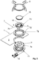
figure 5 is a schematic exploded view of the gas burner offigure 1 . - With reference to the figures,
reference numeral 5 indicates a gas burner in accordance with the present invention, mounted on acooking hob 1. - In particular, the
cooking hob 1 shown infigure 2 comprises asupport plate 2 and fiveburners 5 that are arranged on thesupport plate 2, as well as fivehandles 6 for modulating the air/gas mixture. As shown infigure 4 , thecooking hob 1 is intended to be mounted on a horizontal plane orkitchen top 100. - The
cooking hob 1 comprisesrespective grids 8 for saucepans (which are not illustrated). Eachgrid 8 is associated with arespective burner 5. In an alternative embodiment that is not illustrated, a single grid for all theburners 5 of thecooking hob 1 can be provided. - As illustrated in
figure 4 , acasing 30 is associated with the cooking hob at the seat in which theburner 5 is to be mounted. - The
burner 5 comprises ahollow structure 7 that can have different shapes and sizes. In the non-limiting example illustrated in the figures, thehollow structure 7 has a closed loop annular shape. - At least one of the burners illustrated in
figure 2 can comprise twohollow structures 7 arranged concentrically. Such a burner is called ultra-fast gas burner. - With reference to
figures 3-5 , in thehollow structure 7 aninlet chamber 7a for the inlet of the air/gas mixture and anexpansion chamber 7b for the expansion of air/gas mixture are defined, theexpansion chamber 7b being arranged above theinlet chamber 7a. - Above the
expansion chamber 7b anannular slot 17 for the outlet of the air/gas mixture is defined. Such aslot 17 is configured for supplying the air/gas mixture to a laminar flame exiting from thegas burner 5. - The
slot 17 is elongated along a direction that is substantially vertical, so that the flow of air/gas mixture flows in theslot 17 in a direction that is substantially vertical from theexpansion chamber 7b towards anoutlet mouth 19 of theslot 17. - In the non-limiting example illustrated in the figures, the
slot 17 is continuous and it extends for the entire circumferential extension of thehollow structure 7. - Preferably, the
slot 17 has a width and a depth that are constant. The depth of theslot 17 has the function of homogenizing the laminar flow of the air/gas mixture, more precisely of primary air and gas, so as to form a stable flame. - The
burner 5 moreover comprises anignition device 9 and aflame sensor 10, which are both associated with thehollow structure 7. - The
burner 5 further comprises acollector 11 for the supply of the air/gas mixture. Thecollector 11 is associated with, and in fluid communication with, theinlet chamber 7a. In particular, thecollector 11 is arranged at a height that is not lower than that of theinlet chamber 7a. More in particular, thecollector 11 is arranged at the side of theinlet chamber 7a; its opening mouth in theinlet structure 7a is thus laterally displaced with respect to an axis of symmetry of thehollow structure 7. - With particular reference to
figure 3 , thecollector 11 has aVenturi tube 12 configured to receive gas from anozzle 13 that is arranged at one end of agas feeding tube 14. The gas injected inside theVenturi tube 12 becomes enriched with air, called primary air, and mixes with it. - In accordance with the present invention, the
hollow structure 7 comprises anopening 7c for the inlet of secondary air arranged below theinlet chamber 7a. The secondary air, which is necessary to lick the flame on both sides so as to make a substantially vertical flame, thus enters inside the cavity of thehollow structure 7 from a lower portion of thehollow structure 7 intended to be arranged below thecooking hob 1. In particular, theopening 7c for the inlet of secondary air is defined on alower face 7d of thehollow structure 7. The secondary air passes between saidlower face 7d and the casing 30 (arrows F' infigure 4 ) and enters centrally inside thehollow structure 7 moving towards the top thereof (arrows F" infigure 4 ). - The
expansion chamber 7b, as well as theinlet chamber 7a, are also intended to be arranged below thesupport plate 2, as clearly shown infigures 3 and4 , so as to house theburner 5 as much as possible inside thecooking hob 1. - The
hollow structure 7 comprises adiaphragm 7e interposed between theexpansion chamber 7b and theinlet chamber 7a. - The
diaphragm 7e comprises a plurality ofslots 7f that are arranged circumferentially and angularly adjacent for the passage of the air/gas mixture from theinlet chamber 7a to theexpansion chamber 7b. - The
expansion chamber 7b is thus delimited at the bottom part thereof by thediaphragm 7e. - The
expansion chamber 7b is delimited at a side part thereof by afirst ring nut 7g, which is associated with thesupport plate 2 of thecooking hob 1, and by asecond ring nut 7h which is arranged at a radially inner position with respect to thefirst ring nut 7g. - The
first ring nut 7g and thesecond ring nut 7h also delimit theannular slot 17 for the outlet of the air/gas mixture. In particular, a radiallyouter wall 7g' of thefirst ring nut 7g converges towards theoutlet mouth 19 of theslot 17. - As clearly illustrated in
figures 3 and4 , both thefirst ring nut 7g and thesecond ring nut 7h are in abutment against thediaphragm 7e. - With reference to
figures 4 and5 , thesecond ring nut 7h comprises a radiallyouter wall 7h' which delimits theexpansion chamber 7b (figure 4 ) and a radiallyinner wall 7h" which delimits an innerannular portion 7i of the hollow structure 7 (figure 5 ). - With reference to
figure 4 , the radiallyinner wall 7h" comprises a plurality of angularlyadjacent partition baffles 7h"', separated byrespective openings 7h"", for the passage of the secondary air towards the radiallyouter wall 7h'. - The
burner 5 further comprises an uppercircular closing element 15 for closing thehollow structure 7. - The
circular closing element 15 rests on the upper part of thebaffles 7h"'. - The
burner 5 further comprises anannular slot 16 for the outlet of the secondary air, which is arranged at a radially inner position with respect to theslot 17 for the outlet of the air/gas mixture and in fluid communication with the inlet opening of the secondary air (figures 3 and4 ). - The
annular slot 16 for the outlet of the secondary air is delimited at a side part thereof by thecircular closing element 15 and by the radiallyouter wall 7h' of thesecond ring nut 7h. - As clearly illustrated in
figure 3 , theignition device 9 and theflame sensor 10 are both associated with thesecond ring nut 7h. The respective upper ends 9a and 10a thereof are arranged at an upper portion of thesecond ring nut 7h so as to not project above with respect to thesecond ring nut 7h. - The
ignition device 9 is of the piezoelectric type. The ignition spark is made at the upper end 9a. - The ignition of the air/gas mixture preferably occurs exclusively when a saucepan is positioned above the
gas burner 5. In such a case, the bottom of the saucepan constitutes a stop barrier for the air/gas mixture, which is forced to propagate downwards and reaches, in such a way, the end 9a of theignition device 9. This solution makes it possible to obtain a high safety standard. - With reference to
figures 3 and4 , adiaphragm 20 is provided between theannular slot 17 and theexpansion chamber 7b. Thediaphragm 20 is substantially defined by a wall of thefirst ring nut 7g which radially projects inwards and defines, together with a radially outer surface of the radiallyouter wall 7h' of thesecond ring nut 7h, a passage for the air/gas mixture from theexpansion chamber 7b to theannular slot 17. In fact, thediaphragm 20 forces the air/gas mixture which is in theexpansion chamber 7b to follow a tortuous path before entering in theannular slot 17. The tortuous path makes it possible to homogenise the distribution of air/gas mixture inside theannular slot 17 and to form an even flame. - In operation, the air/gas mixture coming from the
collector 11 firstly passes through theinlet chamber 7a and subsequently evenly distributes inside theexpansion chamber 7b passing through theslots 7f of thediaphragm 7e. From theexpansion chamber 7b the air/gas mixture passes through thediaphragm 20, in theannular slot 17 and supplies the laminar flame exiting from theoutlet mouth 19 of theannular slot 17. The secondary air, on the other hand, enters the cavity of thehollow structure 7 from theopening 7c, evenly distributes in theannular slot 16 passing through theopenings 7h'" of thesecond ring nut 7h and exits from such anannular slot 16 so as to lick the inside of the aforementioned laminar flame. The path of the secondary air from the inlet opening 7a to thesecond ring nut 7h is indicated infigure 4 with the arrows F.
Claims (9)
- Gas burner (5) for a cooking hob (1), comprising at least one hollow structure (7) in which an inlet chamber (7a) for the inlet of an air/gas mixture, an expansion chamber (7b) for the expansion of the air/gas mixture arranged above said inlet chamber (7a), and an annular slot (17) for the outlet of the air/gas mixture arranged above said expansion chamber (7b) and configured for supplying the air/gas mixture to an annular laminar flame exiting from the gas burner (5) are defined, said at least one hollow structure (7) comprising at least one inlet opening (7c) for the inlet of secondary air, wherein said inlet opening (7c) is arranged beneath said inlet chamber (7a), wherein said at least one hollow structure (7) comprises a diaphragm (7e) interposed between said expansion chamber (7b) and said inlet chamber (7a), characterised in that said expansion chamber (7b) is delimited at a bottom part thereof by said diaphragm (7e) and at a side part thereof by a first ring nut (7g) configured to be associated with said cooking hob (1) and in abutment on said diaphragm (7e) and by a second ring nut (7h) arranged at a radially inner position with respect to said first ring nut (7g) and in abutment on said diaphragm (7e).
- Gas burner (5) according to claim 1, wherein said inlet opening (7c) for the inlet of secondary air is defined on a lower face (7d) of said at least one hollow structure (7).
- Gas burner (5) according to claim 1 or 2, comprising a collector (11) for the supply of the air/gas mixture, said collector (11) being associated with said inlet chamber (7a) and arranged at a height not lower than that of said inlet chamber (7a) and/or on a side of said inlet chamber (7a).
- Gas burner (5) according to any one of the previous claims, wherein said diaphragm (7e) comprises a plurality of angularly adjacent slots (7f) for the passage of the air/gas mixture from the inlet chamber (7a) to the expansion chamber (7b).
- Gas burner (5) according to any one of the previous claims, wherein said second ring nut (7h) comprises a radially outer wall (7h') which delimits said expansion chamber (7b) and a radially inner wall (7h") which delimits an inner annular portion (7i) of said at least one hollow structure (7), wherein said radially inner wall (7h") comprises a plurality of angularly adjacent partition baffles (7h"') separated by respective openings (7h"") for the passage of said secondary air towards said radially outer wall (7h').
- Gas burner (5) according to claim 5, comprising a circular closing element (15) resting on the upper part of said partition baffles (7h"').
- Gas burner (5) according to any one of the previous claims, comprising an ignition device (9) and a flame sensor (10) both associated with said second ring nut (7h) and having respective upper ends (9a, 10a) arranged at an upper portion of said second ring nut (7h) and not projecting upwardly with respect to said second ring nut (7h).
- Gas burner (5) according to any one of the previous claims, comprising an annular slot (16) for the outlet of the secondary air arranged at a radially inner position with respect to the annular slot (17) for the outlet of the air/gas mixture and in fluid communication with said inlet opening (7c) for the inlet of the secondary air, wherein preferably said annular slot (16) for the outlet of secondary air is delimited at a side part thereof by said circular closing element (15) and by said radially outer wall (7h') of said second ring nut (7h).
- Cooking hob (1) comprising at least one gas burner (5) according to any one of the previous claims.
Priority Applications (2)
| Application Number | Priority Date | Filing Date | Title |
|---|---|---|---|
| SI201530384T SI3126738T1 (en) | 2014-04-04 | 2015-03-25 | Gas burner for a cooking hob and cooking hob comprising such a gas burner |
| PL15718096T PL3126738T3 (en) | 2014-04-04 | 2015-03-25 | Gas burner for a cooking hob and cooking hob comprising such a gas burner |
Applications Claiming Priority (2)
| Application Number | Priority Date | Filing Date | Title |
|---|---|---|---|
| ITMI20140616 | 2014-04-04 | ||
| PCT/IB2015/052201 WO2015150984A1 (en) | 2014-04-04 | 2015-03-25 | Gas burner for a cooking hob and cooking hob comprising such a gas burner |
Publications (2)
| Publication Number | Publication Date |
|---|---|
| EP3126738A1 EP3126738A1 (en) | 2017-02-08 |
| EP3126738B1 true EP3126738B1 (en) | 2018-06-06 |
Family
ID=50897753
Family Applications (1)
| Application Number | Title | Priority Date | Filing Date |
|---|---|---|---|
| EP15718096.9A Active EP3126738B1 (en) | 2014-04-04 | 2015-03-25 | Gas burner for a cooking hob and cooking hob comprising such a gas burner |
Country Status (5)
| Country | Link |
|---|---|
| EP (1) | EP3126738B1 (en) |
| ES (1) | ES2685870T3 (en) |
| PL (1) | PL3126738T3 (en) |
| SI (1) | SI3126738T1 (en) |
| WO (1) | WO2015150984A1 (en) |
Family Cites Families (10)
| Publication number | Priority date | Publication date | Assignee | Title |
|---|---|---|---|---|
| US1844151A (en) * | 1928-03-03 | 1932-02-09 | Cleveland Heater Co | Gas burner |
| US1956857A (en) * | 1931-02-05 | 1934-05-01 | Autogas Corp | Gas burner |
| US2526748A (en) * | 1946-02-09 | 1950-10-24 | L J Mueller Furnace Company | Gas burner with adjustable flame slot and central secondary air supply |
| FR1077026A (en) * | 1953-03-17 | 1954-11-03 | Fr D Incandescence Par Le Gaz | Gaseous fuel burner |
| GB1544624A (en) * | 1976-05-21 | 1979-04-25 | Ti Domestic Appliances Ltd | Gaseous fuel burners |
| GB2348696A (en) * | 1999-04-07 | 2000-10-11 | Winpo Enterprises Sdn Bhd | Burner with burner plate |
| ITMI20030829A1 (en) | 2003-04-18 | 2004-10-19 | Smeg Spa | GAS STOVE AND HOB. |
| EP2072901B1 (en) * | 2007-12-17 | 2019-06-05 | Candy S.p.A. | Household gas cooktop |
| TR201816544T4 (en) * | 2011-03-31 | 2018-11-21 | Candy Spa | Gas burner unit and stove top. |
| ITMI20111471A1 (en) | 2011-08-01 | 2013-02-02 | Smeg Spa | GAS BURNER FOR A COOKTOP AND A COOKTOP INCLUDING THIS GAS BURNER |
-
2015
- 2015-03-25 PL PL15718096T patent/PL3126738T3/en unknown
- 2015-03-25 SI SI201530384T patent/SI3126738T1/en unknown
- 2015-03-25 ES ES15718096.9T patent/ES2685870T3/en active Active
- 2015-03-25 WO PCT/IB2015/052201 patent/WO2015150984A1/en active Application Filing
- 2015-03-25 EP EP15718096.9A patent/EP3126738B1/en active Active
Non-Patent Citations (1)
| Title |
|---|
| None * |
Also Published As
| Publication number | Publication date |
|---|---|
| PL3126738T3 (en) | 2018-09-28 |
| ES2685870T3 (en) | 2018-10-11 |
| EP3126738A1 (en) | 2017-02-08 |
| WO2015150984A1 (en) | 2015-10-08 |
| SI3126738T1 (en) | 2018-10-30 |
Similar Documents
| Publication | Publication Date | Title |
|---|---|---|
| CA2752508C (en) | Gas burner | |
| US8899972B2 (en) | Burner designed for wide range of input rates | |
| RU2583314C2 (en) | Gas burner with an inwardly directed flame | |
| ES2427858T3 (en) | Cooking surface | |
| US20100092902A1 (en) | Gas burner for cooking appliances | |
| EP3263986A1 (en) | High efficiency high power inner flame burner | |
| EP2773906B1 (en) | A gas burner with inward-facing flame. | |
| EP3343104B1 (en) | Distributed vertical flame burner | |
| EP2359061A1 (en) | Gas burner for domestic cookers | |
| EP3298330A1 (en) | Double flame crown gas burner | |
| EP0797048A1 (en) | Gas burner for kitchen appliances | |
| US10330326B2 (en) | Gas burner assembly for a cooktop appliance | |
| US20230314006A1 (en) | Pan support, gas hob and method for producing a pan support | |
| EP3126738B1 (en) | Gas burner for a cooking hob and cooking hob comprising such a gas burner | |
| ES2648697B1 (en) | GAS BURNER AND DOMESTIC COOKING APPLIANCE | |
| EP2505917B1 (en) | Gas burner unit and cooking top | |
| US20170023245A1 (en) | Dual ring burner ovni | |
| CN110906326B (en) | A kind of burner | |
| US20190086077A1 (en) | Gas burner assembly for a cooktop appliance | |
| KR102264587B1 (en) | Double gas burner | |
| ITMI20111471A1 (en) | GAS BURNER FOR A COOKTOP AND A COOKTOP INCLUDING THIS GAS BURNER | |
| RU149702U1 (en) | GAS BURNER FOR HOUSEHOLD GAS STOVES | |
| CN110906332A (en) | High-efficiency injection combustor | |
| KR20200041539A (en) | High firepower gas burner | |
| ITVE20120024U1 (en) | GAS BURNER FOR COOKING APPLIANCES |
Legal Events
| Date | Code | Title | Description |
|---|---|---|---|
| STAA | Information on the status of an ep patent application or granted ep patent |
Free format text: STATUS: THE INTERNATIONAL PUBLICATION HAS BEEN MADE |
|
| PUAI | Public reference made under article 153(3) epc to a published international application that has entered the european phase |
Free format text: ORIGINAL CODE: 0009012 |
|
| STAA | Information on the status of an ep patent application or granted ep patent |
Free format text: STATUS: REQUEST FOR EXAMINATION WAS MADE |
|
| 17P | Request for examination filed |
Effective date: 20161102 |
|
| AK | Designated contracting states |
Kind code of ref document: A1 Designated state(s): AL AT BE BG CH CY CZ DE DK EE ES FI FR GB GR HR HU IE IS IT LI LT LU LV MC MK MT NL NO PL PT RO RS SE SI SK SM TR |
|
| AX | Request for extension of the european patent |
Extension state: BA ME |
|
| DAV | Request for validation of the european patent (deleted) | ||
| DAX | Request for extension of the european patent (deleted) | ||
| GRAP | Despatch of communication of intention to grant a patent |
Free format text: ORIGINAL CODE: EPIDOSNIGR1 |
|
| STAA | Information on the status of an ep patent application or granted ep patent |
Free format text: STATUS: GRANT OF PATENT IS INTENDED |
|
| INTG | Intention to grant announced |
Effective date: 20171212 |
|
| GRAS | Grant fee paid |
Free format text: ORIGINAL CODE: EPIDOSNIGR3 |
|
| GRAA | (expected) grant |
Free format text: ORIGINAL CODE: 0009210 |
|
| STAA | Information on the status of an ep patent application or granted ep patent |
Free format text: STATUS: THE PATENT HAS BEEN GRANTED |
|
| AK | Designated contracting states |
Kind code of ref document: B1 Designated state(s): AL AT BE BG CH CY CZ DE DK EE ES FI FR GB GR HR HU IE IS IT LI LT LU LV MC MK MT NL NO PL PT RO RS SE SI SK SM TR |
|
| REG | Reference to a national code |
Ref country code: GB Ref legal event code: FG4D |
|
| REG | Reference to a national code |
Ref country code: CH Ref legal event code: EP Ref country code: AT Ref legal event code: REF Ref document number: 1006504 Country of ref document: AT Kind code of ref document: T Effective date: 20180615 |
|
| REG | Reference to a national code |
Ref country code: IE Ref legal event code: FG4D |
|
| REG | Reference to a national code |
Ref country code: DE Ref legal event code: R096 Ref document number: 602015011885 Country of ref document: DE |
|
| REG | Reference to a national code |
Ref country code: NL Ref legal event code: MP Effective date: 20180606 |
|
| REG | Reference to a national code |
Ref country code: ES Ref legal event code: FG2A Ref document number: 2685870 Country of ref document: ES Kind code of ref document: T3 Effective date: 20181011 |
|
| REG | Reference to a national code |
Ref country code: LT Ref legal event code: MG4D |
|
| PG25 | Lapsed in a contracting state [announced via postgrant information from national office to epo] |
Ref country code: BG Free format text: LAPSE BECAUSE OF FAILURE TO SUBMIT A TRANSLATION OF THE DESCRIPTION OR TO PAY THE FEE WITHIN THE PRESCRIBED TIME-LIMIT Effective date: 20180906 Ref country code: CY Free format text: LAPSE BECAUSE OF FAILURE TO SUBMIT A TRANSLATION OF THE DESCRIPTION OR TO PAY THE FEE WITHIN THE PRESCRIBED TIME-LIMIT Effective date: 20180606 Ref country code: FI Free format text: LAPSE BECAUSE OF FAILURE TO SUBMIT A TRANSLATION OF THE DESCRIPTION OR TO PAY THE FEE WITHIN THE PRESCRIBED TIME-LIMIT Effective date: 20180606 Ref country code: LT Free format text: LAPSE BECAUSE OF FAILURE TO SUBMIT A TRANSLATION OF THE DESCRIPTION OR TO PAY THE FEE WITHIN THE PRESCRIBED TIME-LIMIT Effective date: 20180606 Ref country code: SE Free format text: LAPSE BECAUSE OF FAILURE TO SUBMIT A TRANSLATION OF THE DESCRIPTION OR TO PAY THE FEE WITHIN THE PRESCRIBED TIME-LIMIT Effective date: 20180606 Ref country code: NO Free format text: LAPSE BECAUSE OF FAILURE TO SUBMIT A TRANSLATION OF THE DESCRIPTION OR TO PAY THE FEE WITHIN THE PRESCRIBED TIME-LIMIT Effective date: 20180906 |
|
| PG25 | Lapsed in a contracting state [announced via postgrant information from national office to epo] |
Ref country code: GR Free format text: LAPSE BECAUSE OF FAILURE TO SUBMIT A TRANSLATION OF THE DESCRIPTION OR TO PAY THE FEE WITHIN THE PRESCRIBED TIME-LIMIT Effective date: 20180907 Ref country code: RS Free format text: LAPSE BECAUSE OF FAILURE TO SUBMIT A TRANSLATION OF THE DESCRIPTION OR TO PAY THE FEE WITHIN THE PRESCRIBED TIME-LIMIT Effective date: 20180606 Ref country code: HR Free format text: LAPSE BECAUSE OF FAILURE TO SUBMIT A TRANSLATION OF THE DESCRIPTION OR TO PAY THE FEE WITHIN THE PRESCRIBED TIME-LIMIT Effective date: 20180606 Ref country code: LV Free format text: LAPSE BECAUSE OF FAILURE TO SUBMIT A TRANSLATION OF THE DESCRIPTION OR TO PAY THE FEE WITHIN THE PRESCRIBED TIME-LIMIT Effective date: 20180606 |
|
| REG | Reference to a national code |
Ref country code: AT Ref legal event code: MK05 Ref document number: 1006504 Country of ref document: AT Kind code of ref document: T Effective date: 20180606 |
|
| PG25 | Lapsed in a contracting state [announced via postgrant information from national office to epo] |
Ref country code: NL Free format text: LAPSE BECAUSE OF FAILURE TO SUBMIT A TRANSLATION OF THE DESCRIPTION OR TO PAY THE FEE WITHIN THE PRESCRIBED TIME-LIMIT Effective date: 20180606 |
|
| PG25 | Lapsed in a contracting state [announced via postgrant information from national office to epo] |
Ref country code: RO Free format text: LAPSE BECAUSE OF FAILURE TO SUBMIT A TRANSLATION OF THE DESCRIPTION OR TO PAY THE FEE WITHIN THE PRESCRIBED TIME-LIMIT Effective date: 20180606 Ref country code: CZ Free format text: LAPSE BECAUSE OF FAILURE TO SUBMIT A TRANSLATION OF THE DESCRIPTION OR TO PAY THE FEE WITHIN THE PRESCRIBED TIME-LIMIT Effective date: 20180606 Ref country code: SK Free format text: LAPSE BECAUSE OF FAILURE TO SUBMIT A TRANSLATION OF THE DESCRIPTION OR TO PAY THE FEE WITHIN THE PRESCRIBED TIME-LIMIT Effective date: 20180606 Ref country code: AT Free format text: LAPSE BECAUSE OF FAILURE TO SUBMIT A TRANSLATION OF THE DESCRIPTION OR TO PAY THE FEE WITHIN THE PRESCRIBED TIME-LIMIT Effective date: 20180606 Ref country code: EE Free format text: LAPSE BECAUSE OF FAILURE TO SUBMIT A TRANSLATION OF THE DESCRIPTION OR TO PAY THE FEE WITHIN THE PRESCRIBED TIME-LIMIT Effective date: 20180606 Ref country code: IS Free format text: LAPSE BECAUSE OF FAILURE TO SUBMIT A TRANSLATION OF THE DESCRIPTION OR TO PAY THE FEE WITHIN THE PRESCRIBED TIME-LIMIT Effective date: 20181006 |
|
| PG25 | Lapsed in a contracting state [announced via postgrant information from national office to epo] |
Ref country code: SM Free format text: LAPSE BECAUSE OF FAILURE TO SUBMIT A TRANSLATION OF THE DESCRIPTION OR TO PAY THE FEE WITHIN THE PRESCRIBED TIME-LIMIT Effective date: 20180606 |
|
| REG | Reference to a national code |
Ref country code: DE Ref legal event code: R097 Ref document number: 602015011885 Country of ref document: DE |
|
| PLBE | No opposition filed within time limit |
Free format text: ORIGINAL CODE: 0009261 |
|
| STAA | Information on the status of an ep patent application or granted ep patent |
Free format text: STATUS: NO OPPOSITION FILED WITHIN TIME LIMIT |
|
| 26N | No opposition filed |
Effective date: 20190307 |
|
| PG25 | Lapsed in a contracting state [announced via postgrant information from national office to epo] |
Ref country code: DK Free format text: LAPSE BECAUSE OF FAILURE TO SUBMIT A TRANSLATION OF THE DESCRIPTION OR TO PAY THE FEE WITHIN THE PRESCRIBED TIME-LIMIT Effective date: 20180606 |
|
| PG25 | Lapsed in a contracting state [announced via postgrant information from national office to epo] |
Ref country code: MC Free format text: LAPSE BECAUSE OF FAILURE TO SUBMIT A TRANSLATION OF THE DESCRIPTION OR TO PAY THE FEE WITHIN THE PRESCRIBED TIME-LIMIT Effective date: 20180606 |
|
| REG | Reference to a national code |
Ref country code: CH Ref legal event code: PL |
|
| GBPC | Gb: european patent ceased through non-payment of renewal fee |
Effective date: 20190325 |
|
| PG25 | Lapsed in a contracting state [announced via postgrant information from national office to epo] |
Ref country code: AL Free format text: LAPSE BECAUSE OF FAILURE TO SUBMIT A TRANSLATION OF THE DESCRIPTION OR TO PAY THE FEE WITHIN THE PRESCRIBED TIME-LIMIT Effective date: 20180606 Ref country code: LU Free format text: LAPSE BECAUSE OF NON-PAYMENT OF DUE FEES Effective date: 20190325 |
|
| REG | Reference to a national code |
Ref country code: BE Ref legal event code: MM Effective date: 20190331 |
|
| PG25 | Lapsed in a contracting state [announced via postgrant information from national office to epo] |
Ref country code: GB Free format text: LAPSE BECAUSE OF NON-PAYMENT OF DUE FEES Effective date: 20190325 Ref country code: IE Free format text: LAPSE BECAUSE OF NON-PAYMENT OF DUE FEES Effective date: 20190325 Ref country code: CH Free format text: LAPSE BECAUSE OF NON-PAYMENT OF DUE FEES Effective date: 20190331 Ref country code: LI Free format text: LAPSE BECAUSE OF NON-PAYMENT OF DUE FEES Effective date: 20190331 |
|
| PG25 | Lapsed in a contracting state [announced via postgrant information from national office to epo] |
Ref country code: BE Free format text: LAPSE BECAUSE OF NON-PAYMENT OF DUE FEES Effective date: 20190331 |
|
| PG25 | Lapsed in a contracting state [announced via postgrant information from national office to epo] |
Ref country code: MT Free format text: LAPSE BECAUSE OF NON-PAYMENT OF DUE FEES Effective date: 20190325 Ref country code: PT Free format text: LAPSE BECAUSE OF FAILURE TO SUBMIT A TRANSLATION OF THE DESCRIPTION OR TO PAY THE FEE WITHIN THE PRESCRIBED TIME-LIMIT Effective date: 20181008 |
|
| PG25 | Lapsed in a contracting state [announced via postgrant information from national office to epo] |
Ref country code: HU Free format text: LAPSE BECAUSE OF FAILURE TO SUBMIT A TRANSLATION OF THE DESCRIPTION OR TO PAY THE FEE WITHIN THE PRESCRIBED TIME-LIMIT; INVALID AB INITIO Effective date: 20150325 |
|
| PG25 | Lapsed in a contracting state [announced via postgrant information from national office to epo] |
Ref country code: MK Free format text: LAPSE BECAUSE OF FAILURE TO SUBMIT A TRANSLATION OF THE DESCRIPTION OR TO PAY THE FEE WITHIN THE PRESCRIBED TIME-LIMIT Effective date: 20180606 |
|
| PGFP | Annual fee paid to national office [announced via postgrant information from national office to epo] |
Ref country code: FR Payment date: 20230327 Year of fee payment: 9 |
|
| PGFP | Annual fee paid to national office [announced via postgrant information from national office to epo] |
Ref country code: TR Payment date: 20230313 Year of fee payment: 9 Ref country code: PL Payment date: 20230309 Year of fee payment: 9 Ref country code: IT Payment date: 20230307 Year of fee payment: 9 |
|
| P01 | Opt-out of the competence of the unified patent court (upc) registered |
Effective date: 20230529 |
|
| PGFP | Annual fee paid to national office [announced via postgrant information from national office to epo] |
Ref country code: ES Payment date: 20230403 Year of fee payment: 9 |
|
| PGFP | Annual fee paid to national office [announced via postgrant information from national office to epo] |
Ref country code: DE Payment date: 20240327 Year of fee payment: 10 |
|
| PGFP | Annual fee paid to national office [announced via postgrant information from national office to epo] |
Ref country code: SI Payment date: 20240229 Year of fee payment: 10 |