EP0797048A1 - Gas burner for kitchen appliances - Google Patents
Gas burner for kitchen appliances Download PDFInfo
- Publication number
- EP0797048A1 EP0797048A1 EP96109934A EP96109934A EP0797048A1 EP 0797048 A1 EP0797048 A1 EP 0797048A1 EP 96109934 A EP96109934 A EP 96109934A EP 96109934 A EP96109934 A EP 96109934A EP 0797048 A1 EP0797048 A1 EP 0797048A1
- Authority
- EP
- European Patent Office
- Prior art keywords
- chamber
- burner according
- burner
- crown
- gas
- Prior art date
- Legal status (The legal status is an assumption and is not a legal conclusion. Google has not performed a legal analysis and makes no representation as to the accuracy of the status listed.)
- Granted
Links
Images


Classifications
-
- F—MECHANICAL ENGINEERING; LIGHTING; HEATING; WEAPONS; BLASTING
- F23—COMBUSTION APPARATUS; COMBUSTION PROCESSES
- F23D—BURNERS
- F23D14/00—Burners for combustion of a gas, e.g. of a gas stored under pressure as a liquid
- F23D14/02—Premix gas burners, i.e. in which gaseous fuel is mixed with combustion air upstream of the combustion zone
- F23D14/04—Premix gas burners, i.e. in which gaseous fuel is mixed with combustion air upstream of the combustion zone induction type, e.g. Bunsen burner
- F23D14/06—Premix gas burners, i.e. in which gaseous fuel is mixed with combustion air upstream of the combustion zone induction type, e.g. Bunsen burner with radial outlets at the burner head
-
- F—MECHANICAL ENGINEERING; LIGHTING; HEATING; WEAPONS; BLASTING
- F23—COMBUSTION APPARATUS; COMBUSTION PROCESSES
- F23D—BURNERS
- F23D17/00—Burners for combustion conjointly or alternatively of gaseous or liquid or pulverulent fuel
-
- F—MECHANICAL ENGINEERING; LIGHTING; HEATING; WEAPONS; BLASTING
- F23—COMBUSTION APPARATUS; COMBUSTION PROCESSES
- F23D—BURNERS
- F23D2900/00—Special features of, or arrangements for burners using fluid fuels or solid fuels suspended in a carrier gas
- F23D2900/14—Special features of gas burners
- F23D2900/14062—Special features of gas burners for cooking ranges having multiple flame rings
Definitions
- the present invention relates to a burner for kitchen cooking appliances of a type provided with three flame-crowns.
- Gas burners for cooking appliances providing two or three flame-crowns are known in the art.
- three flame-crown burners are known which have one central flame-crown and two circumferential crowns, one directed towards the centre of the burner and the other towards the outside.
- This type of burner is particularly advantageous since it heats the base of the pot more uniformly.
- the British Application No. GB-A-2233444 in the name of Lee, describes a burner comprising a vertical combined gas-supply and support pipe on which is mounted a three-crown head.
- the central crown is coaxial with the vertical supply pipe and communicates with it; three branching ducts extend from this supply pipe to take the mixture of primary air and gas to a circular flame-separator crown, into which two circumferential flame-crowns are cut.
- the secondary air is taken from above the hob for all three crowns.
- the vertical shape of this embodiment makes it not suitable for use on "built-in" kitchen units where the vertical height of the burners must be reduced as much as possible. Furthermore, the internal circumferential crown has a reduced number of flame jets as a result of interference and combustion problems found with this type of burner.
- the EP-A-0534301 in the name of Merloni, describes a burner with a two-crown head. Similar to what is described in German Patent No. 3123751 in the name of the Applicant, in this burner both the primary and secondary air are taken from above the hob and the mixture of primary air and gas is taken to the flame crown by a so-called horizontal Venturi duct.
- the two crowns are cut externally and internally into a circular flame separator whose interior space is divided by separator elements into a plurality of sectors to which the primary air-gas mixture is supplied by a plurality of arms.
- This embodiment has not solved the problem of the earlier art in that, while the horizontal Venturi reduces the height of the burner, there are only two circumferential flame-crowns, of which the internal has a very small number of flame jets.
- the aim of the present invention is to overcome the above problems and produce a three-flame burner of reduced height, which is simple and inexpensive to produce and install, which produces a flame that is substantially free of turbulence and interference and which gives easy access to the gas jet to allow replacement.
- the chamber which produces the Venturi effect has two or more holes or slits in its upper wall to allow the primary air-gas mixture to enter the central crown; such holes or slits are located between the beginning of the diverging length of the bottom wall, where the Venturi effect is off or is substantially reduced, and the end of the flat length of the top wall of the chamber.
- the area of the slits is between 2% and 10% of the area of the upper wall.
- the angle between the two surfaces on the lower wall of the chaser is within the range from 5° to 15°.
- the sidewalls of the Venturi-effect chamber are flared.
- the central flame crown comprises a plurality of pilot flames obtained from cuts connected to the upper cavity of the central body and with a plurality of main flames obtained from holes located on said flared sidewalls of the Venturi chamber.
- Said holes are preferably inclined with respect to the burner vertical axis with an angle within the range from 20 to 40 degrees, and preferably of about 32 degrees.
- the burner according to the invention has numerous advantages over the state of the art.
- the burner has three flame-crowns distributed substantially uniformly, thus giving effectively uniform heating of the pot.
- the flames are essentially free of turbulence or interference.
- the burner has a low profile and can be installed on "built-in" cooking hobs.
- the burner 1 As visible in figures 1 (that is a section along plane A-A of fig. 3) and 6, the burner 1 according to the invention comprises a base 2 to which is attached the gas supply pipe 3 and a seat 4 for the jet 5 (fig.6).
- the base 2 is provided with a plurality of flanges 11 projecting radially to attach it to the hob.
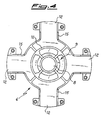
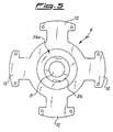
- the base 2 houses a cylindrical element 6; within this element 6 is an internal conduit 8 integral with or assembled onto the same element 6.
- the conduit 8 is integral with the element 6 and forms with it and with the base 2 a mixing chamber 9 for the mixing of the gas from supply 3 and of the primary air coming from above the hob 13 (fig. 6) through the openings 14.
- Such openings 14 are defined by the flange 11, by corresponding flanges 12 on the cylindrical element 6 and by vertical fins 15 on the underside of the flange 12.
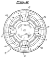
- cylindrical element 6 Above the cylindrical element 6 is a head 16 in which are cut the three crowns 17, 18 and 19, and which shall be better described with reference to figs. 2 and 3.
- the head 16 comprises a central portion 20 on which are provided upper cavity 33 and the grooves of the central flame crown 17.
- the central portion 20 is connected by the arms 21 to a circular element 22, with a substantially U-shaped section, on which are the circumferential flame crowns 18 and 19.
- these flame crowns (comprising a plurality of grooves) are shown only on part of the circular element 22.
- the arms 21 are hollow and have no lower wall, allowing the primary air/gas mixture to enter the circular element 22; the lower boundary of the arms 21 is comprised by the plates 12 on a peripheral part of which the head 16 rests.
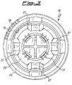
- the lower face of the central portion 20 presents a cavity defined by the wall or flat face 23 and the walls 24 which are flared.
- This cavity houses the upper part 25 of the cylindrical element 6 which is of such height as to leave the upper face 26 of the said part 25 spaced from the flat face 23 of the head 16, when the burner is assembled, by a distance preferably between 1.5 and 3.5 mm.
- Venturi effect chamber 27 is substantially horizontal and defined by face 23 of the central portion 20 of head 16 and face 26 of cylindrical element 6. Face 23 is effectively the upper wall of chamber 27 and face 26 is its lower wall.
- Face 26 is provided with a circular bevel 26a which lies at an angle to the plane of the face 26, such plane is substantially parallel to the above face 23.
- the angle ⁇ between the two planes is preferably between 5 and 15 degrees.
- the Venturi effect ends or is severely reduced near the boundary between the face 26 and the circular bevel 26a.
- Walls 24 are flared (see fig.2) to guide and conduct to arms 21 without turbulence the part of the air/gas mixture flow that strikes said walls on its exit from the Venturi chamber 27.
- the flat wall 23 is provided with two or more slits 28, preferably four slits, one for each wall 24, that connect Venturi chamber 27 with cavity 33 of central portion 20.
- the slits 28 are located in proximity to the zone where the Venturi effect ends or is substantially reduced, and/or downstream of that zone with respect to the gas flow.
- the holes or slits are therefore located in the face 23 in correspondence to the boundary of face 26 defined by the bevel 26a, preferably downstream thereof with respect to the gas flow, and more preferably (as in the embodiment shown) corresponding to the bevel 26a.
- the holes or slits 28 are preferably of such size that their total area is from 2% to 10% of the area of face 23, where the said area is defined as the total area of face 23 including the area of the said hole bounded by the line H in fig.2.
- the burner has two covers 29 and 30 to cover the central portion 20 and the circular element 22 of the head 16, part 20 being raised above the element 22.
- FIG. 9-13 show a further embodiment of the invention in which the central flame crown is obtained on different levels.
- the remaining features of the burner, i.e. Venturi chamber, slits etc., are the same as in above embodiment and are referred to with identical reference numbers.
- central flame ring 17a comprises a first plurality of flames 34 (consisting of grooves or cuts) that are connected to cavity 33 of central portion 20; in other words, flames 34 are obtained on the edge of cavity 33 of central portion 20 by means of grooves that are defined above by a cover 30a.
- flames 34 are pilot flames and main flames 35 are obtained from holes provided on flared walls 24 of the Venturi chamber.
- Holes or flames 35 are angled to the burner vertical axis with an angle ⁇ within the range from 20 to 40 degrees and preferably with an angle ⁇ of about 32 degrees.
- the cover 30a is centered on the upper edge of central portion 20 by means of projecting portions 36 provided on said edge, and it projects beyond it to cover flames 34.
- the flame crowns are defined in such a way that the main flames, which are recognizable in the drawings because of the large grooves, are offset with respect to those of the next crown, to avoid interference with them.
- the primary air/gas mixture flows along the wall 24 and the arms 21 of the head 16 et in part flows to the crown 17 through the plurality of through holes, or slits, 28 in face 23 of central portion 20 of head 16.
- the primary and secondary air are taken from above the hob.
- a means of supplying secondary air to the burner also from below the level of the hob. It has been found that the problem of instability in the flame when lighting the burner from cold can be eliminated in this way.
- FIG.8 The preferred means of supplying secondary air from below the hob is shown in fig.8.
- This figure shows a base 2a provided with a conduit 3 to supply gas and a seat 4 for the gas jet. Similar to base 2 shown in fig.1, also base 2a is provided with arms 11a to attach it to the hob 13.
- arms 11a in base 2a are joined to each other to form the flange 32, in which are cut slits 31 for the passage of air from below the hob to above the hob.
Abstract
Description
- The present invention relates to a burner for kitchen cooking appliances of a type provided with three flame-crowns.
- Gas burners for cooking appliances providing two or three flame-crowns are known in the art. In particular, three flame-crown burners are known which have one central flame-crown and two circumferential crowns, one directed towards the centre of the burner and the other towards the outside.
- This type of burner is particularly advantageous since it heats the base of the pot more uniformly.
- The British Application No. GB-A-2233444, in the name of Lee, describes a burner comprising a vertical combined gas-supply and support pipe on which is mounted a three-crown head. The central crown is coaxial with the vertical supply pipe and communicates with it; three branching ducts extend from this supply pipe to take the mixture of primary air and gas to a circular flame-separator crown, into which two circumferential flame-crowns are cut. The secondary air is taken from above the hob for all three crowns.
- The vertical shape of this embodiment makes it not suitable for use on "built-in" kitchen units where the vertical height of the burners must be reduced as much as possible. Furthermore, the internal circumferential crown has a reduced number of flame jets as a result of interference and combustion problems found with this type of burner.
- The EP-A-0534301, in the name of Merloni, describes a burner with a two-crown head. Similar to what is described in German Patent No. 3123751 in the name of the Applicant, in this burner both the primary and secondary air are taken from above the hob and the mixture of primary air and gas is taken to the flame crown by a so-called horizontal Venturi duct. The two crowns are cut externally and internally into a circular flame separator whose interior space is divided by separator elements into a plurality of sectors to which the primary air-gas mixture is supplied by a plurality of arms.
- This embodiment has not solved the problem of the earlier art in that, while the horizontal Venturi reduces the height of the burner, there are only two circumferential flame-crowns, of which the internal has a very small number of flame jets.
- The aim of the present invention is to overcome the above problems and produce a three-flame burner of reduced height, which is simple and inexpensive to produce and install, which produces a flame that is substantially free of turbulence and interference and which gives easy access to the gas jet to allow replacement.
- This aim is achieved by the present invention, which relates to a gas burner for domestic use characterized according to Claim 1.
- According to a preferential embodiment of the invention, the chamber which produces the Venturi effect has two or more holes or slits in its upper wall to allow the primary air-gas mixture to enter the central crown; such holes or slits are located between the beginning of the diverging length of the bottom wall, where the Venturi effect is off or is substantially reduced, and the end of the flat length of the top wall of the chamber.
- Preferably, the area of the slits is between 2% and 10% of the area of the upper wall.
- According to another preferential embodiment of the invention, the angle between the two surfaces on the lower wall of the chaser is within the range from 5° to 15°.
- According to another aspect of the invention, the sidewalls of the Venturi-effect chamber are flared.
- According to another aspect of the invention, there is provision for supplying secondary air to the burner from above or below the hob.
- According to a further embodiment of the invention, the central flame crown comprises a plurality of pilot flames obtained from cuts connected to the upper cavity of the central body and with a plurality of main flames obtained from holes located on said flared sidewalls of the Venturi chamber. Said holes are preferably inclined with respect to the burner vertical axis with an angle within the range from 20 to 40 degrees, and preferably of about 32 degrees.
- The burner according to the invention has numerous advantages over the state of the art. The burner has three flame-crowns distributed substantially uniformly, thus giving effectively uniform heating of the pot. The flames are essentially free of turbulence or interference.
- The burner has a low profile and can be installed on "built-in" cooking hobs.
- The invention will now be described in more detail with reference to the attached drawings which are by way of example and not limiting, in which:
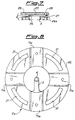
- Fig.1 is a partial sectioned exploded view of an embodiment according to the invention;
- Figs. 2 and 3 are plan views from below and above respectively of the upper plate of the burner shown in fig.1;
- Fig. 4 is a view from below of an element of the burner shown in fig.1;
- Fig.5 is a view from above of the detail shown in fig.4;
- Fig.6 is a side view of the burner according to the invention mounted on a hob;
- Fig.7 is a sectioned view of the Venturi chamber of the burner according to the invention;
- Fig.8 is a plan view of the base element of the burner according to the invention;
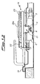
- Figures 9 and 10 are enlarged, partial and sectioned views along planes B-B and C-C (fig.11) of a further embodiment of the invention;
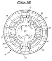
- Fig.11 and fig.12 are plan views from below and above, respectively, of the upper plate of the burner according to figures 9 and 10; and
- Fig.13 is a lateral view of the embodiment according to figures 9-12.
- As visible in figures 1 (that is a section along plane A-A of fig. 3) and 6, the burner 1 according to the invention comprises a
base 2 to which is attached thegas supply pipe 3 and aseat 4 for the jet 5 (fig.6). Thebase 2 is provided with a plurality offlanges 11 projecting radially to attach it to the hob. Thebase 2 houses acylindrical element 6; within thiselement 6 is aninternal conduit 8 integral with or assembled onto thesame element 6. In the embodiment shown, theconduit 8 is integral with theelement 6 and forms with it and with thebase 2 a mixing chamber 9 for the mixing of the gas fromsupply 3 and of the primary air coming from above the hob 13 (fig. 6) through theopenings 14.Such openings 14 are defined by theflange 11, bycorresponding flanges 12 on thecylindrical element 6 and byvertical fins 15 on the underside of theflange 12. - Above the
cylindrical element 6 is ahead 16 in which are cut the threecrowns - The
head 16 comprises acentral portion 20 on which are providedupper cavity 33 and the grooves of thecentral flame crown 17. Thecentral portion 20 is connected by thearms 21 to acircular element 22, with a substantially U-shaped section, on which are thecircumferential flame crowns circular element 22. Thearms 21 are hollow and have no lower wall, allowing the primary air/gas mixture to enter thecircular element 22; the lower boundary of thearms 21 is comprised by theplates 12 on a peripheral part of which thehead 16 rests. - As can be seen from figs. 1 and 2, the lower face of the
central portion 20 presents a cavity defined by the wall orflat face 23 and thewalls 24 which are flared. This cavity houses theupper part 25 of thecylindrical element 6 which is of such height as to leave theupper face 26 of the saidpart 25 spaced from theflat face 23 of thehead 16, when the burner is assembled, by a distance preferably between 1.5 and 3.5 mm. In this way a substantially horizontal Venturi chamber 27 (fig.7) is created which allows the gas access to the flame crowns 17 - 19. As mentioned above and as can be more easily seen in fig.7, Venturieffect chamber 27 is substantially horizontal and defined byface 23 of thecentral portion 20 ofhead 16 andface 26 ofcylindrical element 6.Face 23 is effectively the upper wall ofchamber 27 andface 26 is its lower wall. -
Face 26 is provided with acircular bevel 26a which lies at an angle to the plane of theface 26, such plane is substantially parallel to theabove face 23. The angle α between the two planes is preferably between 5 and 15 degrees. - The Venturi effect ends or is severely reduced near the boundary between the
face 26 and thecircular bevel 26a. -
Walls 24 are flared (see fig.2) to guide and conduct toarms 21 without turbulence the part of the air/gas mixture flow that strikes said walls on its exit from the Venturichamber 27. - According to the present invention, the
flat wall 23 is provided with two ormore slits 28, preferably four slits, one for eachwall 24, that connect Venturichamber 27 withcavity 33 ofcentral portion 20. - The
slits 28 are located in proximity to the zone where the Venturi effect ends or is substantially reduced, and/or downstream of that zone with respect to the gas flow. In the embodiment according to the present invention, the holes or slits are therefore located in theface 23 in correspondence to the boundary offace 26 defined by thebevel 26a, preferably downstream thereof with respect to the gas flow, and more preferably (as in the embodiment shown) corresponding to thebevel 26a. - The holes or
slits 28 are preferably of such size that their total area is from 2% to 10% of the area offace 23, where the said area is defined as the total area offace 23 including the area of the said hole bounded by the line H in fig.2. - As can be seen in fig.6 embodiment, the burner has two
covers central portion 20 and thecircular element 22 of thehead 16,part 20 being raised above theelement 22. - Figures 9-13 show a further embodiment of the invention in which the central flame crown is obtained on different levels. The remaining features of the burner, i.e. Venturi chamber, slits etc., are the same as in above embodiment and are referred to with identical reference numbers.
- As can be seen in figures 9 and 10, that are sectional views along plane B-B and C-C of fig. 11,
central flame ring 17a comprises a first plurality of flames 34 (consisting of grooves or cuts) that are connected tocavity 33 ofcentral portion 20; in other words,flames 34 are obtained on the edge ofcavity 33 ofcentral portion 20 by means of grooves that are defined above by acover 30a. These flames are pilot flames andmain flames 35 are obtained from holes provided on flaredwalls 24 of the Venturi chamber. - Holes or
flames 35 are angled to the burner vertical axis with an angle β within the range from 20 to 40 degrees and preferably with an angle β of about 32 degrees. - The
cover 30a is centered on the upper edge ofcentral portion 20 by means of projectingportions 36 provided on said edge, and it projects beyond it to coverflames 34. - In all the embodiments of the invention the flame crowns are defined in such a way that the main flames, which are recognizable in the drawings because of the large grooves, are offset with respect to those of the next crown, to avoid interference with them.
- Operation is similar in both disclosed embodiments. Primary air arriving through
openings 14 is mixed with gas in chamber 9. From here it flows tohorizontal Venturi chamber 27 throughduct 8. - After passing through the
Venturi effect chamber 27, in the embodiment of fig. 1-8 the primary air/gas mixture flows along thewall 24 and thearms 21 of thehead 16 et in part flows to thecrown 17 through the plurality of through holes, or slits, 28 inface 23 ofcentral portion 20 ofhead 16. - The same happens in the embodiment of fig. 9-13, with the difference that in this case a part of the mixture flows through the inclined slits or
flames 35 which constitute the principal flames of the central crown. - As mentioned above, in the burner according to the present invention the primary and secondary air are taken from above the hob. In a preferred embodiment there is provision for a means of supplying secondary air to the burner also from below the level of the hob. It has been found that the problem of instability in the flame when lighting the burner from cold can be eliminated in this way.
- The preferred means of supplying secondary air from below the hob is shown in fig.8. This figure shows a
base 2a provided with aconduit 3 to supply gas and aseat 4 for the gas jet. Similar tobase 2 shown in fig.1, alsobase 2a is provided witharms 11a to attach it to thehob 13. - Unlike the embodiment shown in fig.1, however,
arms 11a inbase 2a are joined to each other to form theflange 32, in which are cutslits 31 for the passage of air from below the hob to above the hob.
Claims (12)
- A burner (1) for kitchen appliances, comprising a central flame crown (17; 17a) and two concentric circumferential flame crowns (18, 19), means (21) of supplying a mixture of air and gas to said circumferential crowns (18,19) and means of supplying said mixture to said central flame crown from a chamber (27) by Venturi effect, characterized in that said chamber (27) is substantially horizontal and the said means of supplying a mixture of air and gas to the said central crown (17, 17a) comprises a plurality of holes or slots (28) provided on the upper wall (23) of said chamber in correspondence to the zone of cessation of the Venturi effect and/or downstream of the said zone, with respect to the flow of the said gas-mixture.
- A burner according to Claim 1, wherein the area of the said slits is between 2% and 10% of the total area of the said wall (23).
- A burner according to Claim 1 or 2, comprising a peripheral portion (26a) adjacent to the said Venturi effect chamber (27), which lies in a plane at an angle to the plane (26) of the said chamber.
- A burner according to any of the preceding Claims, wherein the angle between the two said planes is between 5 and 15 degrees.
- A burner according to any of the preceding Claims, wherein said angled peripheral portion (26a) is on the lower wall of the chamber (27).
- A burner according to Claim 5, wherein the said holes or slits (28) are located between the said angle and the end of the upper wall (23) of the said chamber.
- A burner according to any of the preceding Claims, further comprising flared walls (24) located laterally of the said chamber (27).
- A burner according to any of the preceding Claims, wherein the pilot flames (34) and the main flames (35) of the said central flame crown (17a) are located on different planes, said main flames being located on the lateral walls (24) of said Venturi chamber.
- A burner according to Claim 8, wherein said main flames (34) are angled to the vertical axis of said burner by an angle within the range from 20 to 40 degrees.
- A burner according to Claim 9, wherein said angle is about 32 degrees.
- A burner according to any previous Claim, wherein said main flames of said central flame crown (17, 17a) are offset from the main flames of said inner circumferential flame crown (19).
- A burner according to any previous Claim, further comprising a means (31) of taking secondary air for the said flame crowns from below the said hob.
Priority Applications (10)
| Application Number | Priority Date | Filing Date | Title |
|---|---|---|---|
| ES96109934T ES2107401T3 (en) | 1996-03-19 | 1996-06-20 | GAS BURNER FOR KITCHEN DEVICES. |
| SI9630091T SI0797048T1 (en) | 1996-03-19 | 1996-06-20 | Gas burner for kitchen appliances |
| DE69604153T DE69604153T2 (en) | 1996-03-19 | 1996-06-20 | Gas burners for kitchen appliances |
| EP96109934A EP0797048B1 (en) | 1996-03-19 | 1996-06-20 | Gas burner for kitchen appliances |
| DE0797048T DE797048T1 (en) | 1996-03-19 | 1996-06-20 | Gas burners for kitchen appliances |
| AT96109934T ATE184384T1 (en) | 1996-03-19 | 1996-06-20 | GAS BURNERS FOR KITCHEN APPLIANCES |
| TR97/00179A TR199700179A1 (en) | 1996-03-19 | 1997-03-10 | A gas stove for kitchen installations. |
| YU10097A YU49044B (en) | 1996-03-19 | 1997-03-17 | Gas burner for kitchen appliances |
| PL97319027A PL183105B1 (en) | 1996-03-19 | 1997-03-18 | Kitchen appliance gas burner |
| KR1019970009334A KR100453121B1 (en) | 1996-03-19 | 1997-03-19 | Kitchen burner |
Applications Claiming Priority (3)
| Application Number | Priority Date | Filing Date | Title |
|---|---|---|---|
| EP96830125 | 1996-03-19 | ||
| EP96830125 | 1996-03-19 | ||
| EP96109934A EP0797048B1 (en) | 1996-03-19 | 1996-06-20 | Gas burner for kitchen appliances |
Publications (2)
| Publication Number | Publication Date |
|---|---|
| EP0797048A1 true EP0797048A1 (en) | 1997-09-24 |
| EP0797048B1 EP0797048B1 (en) | 1999-09-08 |
Family
ID=26142009
Family Applications (1)
| Application Number | Title | Priority Date | Filing Date |
|---|---|---|---|
| EP96109934A Expired - Lifetime EP0797048B1 (en) | 1996-03-19 | 1996-06-20 | Gas burner for kitchen appliances |
Country Status (9)
| Country | Link |
|---|---|
| EP (1) | EP0797048B1 (en) |
| KR (1) | KR100453121B1 (en) |
| AT (1) | ATE184384T1 (en) |
| DE (2) | DE797048T1 (en) |
| ES (1) | ES2107401T3 (en) |
| PL (1) | PL183105B1 (en) |
| SI (1) | SI0797048T1 (en) |
| TR (1) | TR199700179A1 (en) |
| YU (1) | YU49044B (en) |
Cited By (15)
| Publication number | Priority date | Publication date | Assignee | Title |
|---|---|---|---|---|
| WO2002002991A1 (en) | 2000-07-06 | 2002-01-10 | Sabaf S.P.A. | Burner with internal separator |
| WO2003036168A1 (en) * | 2001-10-24 | 2003-05-01 | Officine Meccaniche Defendi S.R.L. | Gas burner with several flame sectors |
| WO2003069231A1 (en) | 2002-02-18 | 2003-08-21 | Sabaf S.P.A. | Cooking hob from tempered glass or other thermodegradable materials |
| WO2004092655A1 (en) * | 2003-04-18 | 2004-10-28 | So.M.I. Press-Societa' Metalli Iniettati S.P.A. | Gas cooker burner of improved type |
| WO2004113792A1 (en) * | 2003-06-23 | 2004-12-29 | Sami Srl | Triple crown gas burner |
| EP1531304A2 (en) * | 2003-11-11 | 2005-05-18 | FAGOR, S.Coop | Triple crown gas burner for cooking hobs |
| WO2005080870A1 (en) | 2004-01-23 | 2005-09-01 | Burner Systems International (Bsi) | Gas burner for a cooking appliance |
| WO2006077058A1 (en) * | 2005-01-20 | 2006-07-27 | Defendi Italy S.R.L. | Gas burner, in particular for domestic cooking appliances |
| KR100678283B1 (en) | 2005-01-19 | 2007-02-02 | 동양매직 주식회사 | Gas burner |
| WO2010067391A1 (en) * | 2008-12-12 | 2010-06-17 | Sabaf S.P.A. | Gas burner for domestic cookers |
| CN102062400A (en) * | 2011-01-25 | 2011-05-18 | 叶鸿煦 | Energy-saving combustor for steaming and frying fish |
| WO2011160762A1 (en) * | 2010-06-23 | 2011-12-29 | Electrolux Home Products Corporation N. V. | Gas stove |
| CN103256595A (en) * | 2013-05-16 | 2013-08-21 | 广东万和电气有限公司 | Burner used for gas stove |
| WO2016142872A1 (en) * | 2015-03-10 | 2016-09-15 | Defendi Italy S.R.L. | Improved gas bruner |
| EP2629010A3 (en) * | 2012-02-16 | 2018-01-10 | Jinhong Liang | Burner for gas ovens |
Families Citing this family (4)
| Publication number | Priority date | Publication date | Assignee | Title |
|---|---|---|---|---|
| EP0903538A1 (en) * | 1997-09-23 | 1999-03-24 | SABAF S.p.A. | Gas burner |
| KR100730576B1 (en) | 2005-08-24 | 2007-06-21 | 공재철 | portable gas range |
| IT1400182B1 (en) | 2010-05-19 | 2013-05-17 | Defendi Italy Srl | GAS BURNER WITH MORE FLAME CHAINS. |
| CN102230622B (en) * | 2011-06-21 | 2013-04-17 | 美的集团股份有限公司 | Burner for gas stove |
Citations (4)
| Publication number | Priority date | Publication date | Assignee | Title |
|---|---|---|---|---|
| DE3123751A1 (en) * | 1981-06-15 | 1982-12-30 | Sabaf S.p.A., Lumezzane, Brescia | Burner for baking ovens or cooking plates operated with gas |
| GB2233444A (en) * | 1989-08-16 | 1991-01-09 | Lee Cheng San | Cooking apparatus |
| EP0534301A2 (en) * | 1991-09-26 | 1993-03-31 | MERLONI ELETTRODOMESTICI S.p.A. | Gas burner for food cooking |
| EP0552135A2 (en) * | 1992-01-13 | 1993-07-21 | SMEG S.p.A. | Improved gas cooker burner with three concentric flames |
Family Cites Families (4)
| Publication number | Priority date | Publication date | Assignee | Title |
|---|---|---|---|---|
| US2233444A (en) * | 1939-09-19 | 1941-03-04 | Hubert O Woody | Shearing machine |
| FR2642147B1 (en) * | 1989-01-20 | 1991-05-03 | Sourdillon Airindex Sa | EXTRA-FLAT TYPE GAS BURNER ARRANGEMENT |
| US5133334A (en) * | 1989-12-12 | 1992-07-28 | Robertshaw Controls Company | Burner construction and method of making the same |
| KR100187029B1 (en) * | 1995-12-28 | 1999-03-20 | 배순훈 | Double venturi burner |
-
1996
- 1996-06-20 SI SI9630091T patent/SI0797048T1/en unknown
- 1996-06-20 DE DE0797048T patent/DE797048T1/en active Pending
- 1996-06-20 ES ES96109934T patent/ES2107401T3/en not_active Expired - Lifetime
- 1996-06-20 EP EP96109934A patent/EP0797048B1/en not_active Expired - Lifetime
- 1996-06-20 AT AT96109934T patent/ATE184384T1/en active
- 1996-06-20 DE DE69604153T patent/DE69604153T2/en not_active Expired - Lifetime
-
1997
- 1997-03-10 TR TR97/00179A patent/TR199700179A1/en unknown
- 1997-03-17 YU YU10097A patent/YU49044B/en unknown
- 1997-03-18 PL PL97319027A patent/PL183105B1/en unknown
- 1997-03-19 KR KR1019970009334A patent/KR100453121B1/en not_active IP Right Cessation
Patent Citations (4)
| Publication number | Priority date | Publication date | Assignee | Title |
|---|---|---|---|---|
| DE3123751A1 (en) * | 1981-06-15 | 1982-12-30 | Sabaf S.p.A., Lumezzane, Brescia | Burner for baking ovens or cooking plates operated with gas |
| GB2233444A (en) * | 1989-08-16 | 1991-01-09 | Lee Cheng San | Cooking apparatus |
| EP0534301A2 (en) * | 1991-09-26 | 1993-03-31 | MERLONI ELETTRODOMESTICI S.p.A. | Gas burner for food cooking |
| EP0552135A2 (en) * | 1992-01-13 | 1993-07-21 | SMEG S.p.A. | Improved gas cooker burner with three concentric flames |
Cited By (28)
| Publication number | Priority date | Publication date | Assignee | Title |
|---|---|---|---|---|
| CZ299592B6 (en) * | 2000-07-06 | 2008-09-10 | Sabaf S. P. A. | Burner for cookers |
| AU2001262598B2 (en) * | 2000-07-06 | 2005-05-05 | Sabaf S.P.A | Burner with internal separator |
| US7001176B2 (en) | 2000-07-06 | 2006-02-21 | Sabaf S.P.A. | Burner with internal separator |
| WO2002002991A1 (en) | 2000-07-06 | 2002-01-10 | Sabaf S.P.A. | Burner with internal separator |
| WO2003036168A1 (en) * | 2001-10-24 | 2003-05-01 | Officine Meccaniche Defendi S.R.L. | Gas burner with several flame sectors |
| WO2003069231A1 (en) | 2002-02-18 | 2003-08-21 | Sabaf S.P.A. | Cooking hob from tempered glass or other thermodegradable materials |
| WO2004092655A1 (en) * | 2003-04-18 | 2004-10-28 | So.M.I. Press-Societa' Metalli Iniettati S.P.A. | Gas cooker burner of improved type |
| WO2004113792A1 (en) * | 2003-06-23 | 2004-12-29 | Sami Srl | Triple crown gas burner |
| EP1531304A2 (en) * | 2003-11-11 | 2005-05-18 | FAGOR, S.Coop | Triple crown gas burner for cooking hobs |
| EP1531304A3 (en) * | 2003-11-11 | 2009-07-29 | Coprecitec, S.L. | Triple crown gas burner for cooking hobs |
| WO2005080870A1 (en) | 2004-01-23 | 2005-09-01 | Burner Systems International (Bsi) | Gas burner for a cooking appliance |
| KR100678283B1 (en) | 2005-01-19 | 2007-02-02 | 동양매직 주식회사 | Gas burner |
| WO2006077058A1 (en) * | 2005-01-20 | 2006-07-27 | Defendi Italy S.R.L. | Gas burner, in particular for domestic cooking appliances |
| US9194578B2 (en) | 2008-12-12 | 2015-11-24 | Sabaf S.P.A | Gas burner for domestic cookers |
| WO2010067391A1 (en) * | 2008-12-12 | 2010-06-17 | Sabaf S.P.A. | Gas burner for domestic cookers |
| AU2008365043B2 (en) * | 2008-12-12 | 2015-06-04 | Sabaf S.P.A. | Gas burner for domestic cookers |
| WO2011160762A1 (en) * | 2010-06-23 | 2011-12-29 | Electrolux Home Products Corporation N. V. | Gas stove |
| EP2402654A1 (en) * | 2010-06-23 | 2012-01-04 | Electrolux Home Products Corporation N.V. | Gas stove |
| CN102893088A (en) * | 2010-06-23 | 2013-01-23 | 伊莱克斯家用产品股份有限公司 | Gas stove |
| US9593854B2 (en) | 2010-06-23 | 2017-03-14 | Electrolux Home Products Corporation N.V. | Gas stove |
| AU2011269355B2 (en) * | 2010-06-23 | 2014-11-27 | Electrolux Home Products Corporation N. V. | Gas stove |
| CN102893088B (en) * | 2010-06-23 | 2015-11-25 | 伊莱克斯家用产品股份有限公司 | Gas burner |
| CN102062400A (en) * | 2011-01-25 | 2011-05-18 | 叶鸿煦 | Energy-saving combustor for steaming and frying fish |
| EP2629010A3 (en) * | 2012-02-16 | 2018-01-10 | Jinhong Liang | Burner for gas ovens |
| CN103256595B (en) * | 2013-05-16 | 2015-10-28 | 广东万和电气有限公司 | For the burner of gas-cooker |
| CN103256595A (en) * | 2013-05-16 | 2013-08-21 | 广东万和电气有限公司 | Burner used for gas stove |
| WO2016142872A1 (en) * | 2015-03-10 | 2016-09-15 | Defendi Italy S.R.L. | Improved gas bruner |
| RU2701432C2 (en) * | 2015-03-10 | 2019-09-26 | Дефенди Итали С.Р.Л. | Improved gas burner |
Also Published As
| Publication number | Publication date |
|---|---|
| SI0797048T1 (en) | 1999-12-31 |
| EP0797048B1 (en) | 1999-09-08 |
| KR100453121B1 (en) | 2004-12-23 |
| ATE184384T1 (en) | 1999-09-15 |
| DE69604153T2 (en) | 2000-05-25 |
| TR199700179A1 (en) | 1997-10-21 |
| PL183105B1 (en) | 2002-05-31 |
| DE797048T1 (en) | 1998-03-12 |
| KR970066277A (en) | 1997-10-13 |
| ES2107401T1 (en) | 1997-12-01 |
| YU49044B (en) | 2003-07-07 |
| ES2107401T3 (en) | 2000-02-01 |
| PL319027A1 (en) | 1997-09-29 |
| YU10097A (en) | 1999-09-27 |
| DE69604153D1 (en) | 1999-10-14 |
Similar Documents
| Publication | Publication Date | Title |
|---|---|---|
| EP0797048B1 (en) | Gas burner for kitchen appliances | |
| US6035846A (en) | Gas burner | |
| EP2399072B1 (en) | Gas burner | |
| US8746229B2 (en) | Gas burner system for food cooking appliances | |
| CA2712208C (en) | Triple flame section burner | |
| EP2310742B1 (en) | Cooktop swirl burner | |
| US5186620A (en) | Gas burner nozzle | |
| US6332460B1 (en) | Gas burner particularly for incorporated cooking hobs of a gas cooker | |
| US8899972B2 (en) | Burner designed for wide range of input rates | |
| EP1297281B1 (en) | Burner with internal separator | |
| US4572154A (en) | Gas range | |
| RU2387923C2 (en) | System of gas burner for domestic gas stoves, and upper part of gas stove | |
| US20100092902A1 (en) | Gas burner for cooking appliances | |
| US20050142511A1 (en) | Cooperating bridge burner system | |
| US20100154776A1 (en) | Cooking range burner head assembly | |
| EP3343104B1 (en) | Distributed vertical flame burner | |
| EP3263986A1 (en) | High efficiency high power inner flame burner | |
| EP1531304B1 (en) | Triple crown gas burner for cooking hobs | |
| US11359818B2 (en) | Gas burner | |
| EP1249665B1 (en) | Gas burner and cooktop provided with such gas burner | |
| EP1649216B1 (en) | Triple crown gas burner | |
| KR101019559B1 (en) | Head for high fire of portablegas range | |
| US11774090B2 (en) | Double-stacked gas burner | |
| SU991111A1 (en) | Burner nozzle | |
| MXPA01005655A (en) | Kitchen gas burner. |
Legal Events
| Date | Code | Title | Description |
|---|---|---|---|
| PUAI | Public reference made under article 153(3) epc to a published international application that has entered the european phase |
Free format text: ORIGINAL CODE: 0009012 |
|
| AK | Designated contracting states |
Kind code of ref document: A1 Designated state(s): AT BE DE ES FR GB IE IT |
|
| AX | Request for extension of the european patent |
Free format text: AL;LT;LV;SI PAYMENT 970210 |
|
| 17P | Request for examination filed |
Effective date: 19970807 |
|
| ITCL | It: translation for ep claims filed |
Representative=s name: MARIETTI & GISLON S.R.L. |
|
| EL | Fr: translation of claims filed | ||
| REG | Reference to a national code |
Ref country code: ES Ref legal event code: BA2A Ref document number: 2107401 Country of ref document: ES Kind code of ref document: T1 |
|
| RBV | Designated contracting states (corrected) |
Designated state(s): AT BE DE ES FR GB IE IT |
|
| TCAT | At: translation of patent claims filed | ||
| DET | De: translation of patent claims | ||
| 17Q | First examination report despatched |
Effective date: 19980403 |
|
| GRAG | Despatch of communication of intention to grant |
Free format text: ORIGINAL CODE: EPIDOS AGRA |
|
| GRAG | Despatch of communication of intention to grant |
Free format text: ORIGINAL CODE: EPIDOS AGRA |
|
| GRAG | Despatch of communication of intention to grant |
Free format text: ORIGINAL CODE: EPIDOS AGRA |
|
| GRAH | Despatch of communication of intention to grant a patent |
Free format text: ORIGINAL CODE: EPIDOS IGRA |
|
| GRAH | Despatch of communication of intention to grant a patent |
Free format text: ORIGINAL CODE: EPIDOS IGRA |
|
| GRAA | (expected) grant |
Free format text: ORIGINAL CODE: 0009210 |
|
| AK | Designated contracting states |
Kind code of ref document: B1 Designated state(s): AT BE DE ES FR GB IE IT |
|
| AX | Request for extension of the european patent |
Free format text: SI PAYMENT 19970210 |
|
| REF | Corresponds to: |
Ref document number: 184384 Country of ref document: AT Date of ref document: 19990915 Kind code of ref document: T |
|
| REF | Corresponds to: |
Ref document number: 69604153 Country of ref document: DE Date of ref document: 19991014 |
|
| ET | Fr: translation filed | ||
| REG | Reference to a national code |
Ref country code: IE Ref legal event code: FG4D |
|
| ITF | It: translation for a ep patent filed |
Owner name: MARIETTI E GISLON S.R.L. |
|
| REG | Reference to a national code |
Ref country code: ES Ref legal event code: FG2A Ref document number: 2107401 Country of ref document: ES Kind code of ref document: T3 |
|
| PLBE | No opposition filed within time limit |
Free format text: ORIGINAL CODE: 0009261 |
|
| STAA | Information on the status of an ep patent application or granted ep patent |
Free format text: STATUS: NO OPPOSITION FILED WITHIN TIME LIMIT |
|
| 26N | No opposition filed | ||
| REG | Reference to a national code |
Ref country code: GB Ref legal event code: IF02 |
|
| REG | Reference to a national code |
Ref country code: SI Ref legal event code: IF |
|
| REG | Reference to a national code |
Ref country code: FR Ref legal event code: PLFP Year of fee payment: 20 |
|
| PGFP | Annual fee paid to national office [announced via postgrant information from national office to epo] |
Ref country code: ES Payment date: 20150512 Year of fee payment: 20 Ref country code: GB Payment date: 20150526 Year of fee payment: 20 |
|
| PGFP | Annual fee paid to national office [announced via postgrant information from national office to epo] |
Ref country code: IE Payment date: 20150430 Year of fee payment: 20 Ref country code: FR Payment date: 20150429 Year of fee payment: 20 Ref country code: IT Payment date: 20150505 Year of fee payment: 20 Ref country code: AT Payment date: 20150515 Year of fee payment: 20 |
|
| PGFP | Annual fee paid to national office [announced via postgrant information from national office to epo] |
Ref country code: DE Payment date: 20150701 Year of fee payment: 20 |
|
| PGFP | Annual fee paid to national office [announced via postgrant information from national office to epo] |
Ref country code: BE Payment date: 20150526 Year of fee payment: 20 |
|
| REG | Reference to a national code |
Ref country code: DE Ref legal event code: R071 Ref document number: 69604153 Country of ref document: DE |
|
| REG | Reference to a national code |
Ref country code: GB Ref legal event code: PE20 Expiry date: 20160619 |
|
| REG | Reference to a national code |
Ref country code: IE Ref legal event code: MK9A |
|
| PG25 | Lapsed in a contracting state [announced via postgrant information from national office to epo] |
Ref country code: GB Free format text: LAPSE BECAUSE OF EXPIRATION OF PROTECTION Effective date: 20160619 |
|
| REG | Reference to a national code |
Ref country code: AT Ref legal event code: MK07 Ref document number: 184384 Country of ref document: AT Kind code of ref document: T Effective date: 20160620 |
|
| REG | Reference to a national code |
Ref country code: ES Ref legal event code: FD2A Effective date: 20160927 |
|
| PG25 | Lapsed in a contracting state [announced via postgrant information from national office to epo] |
Ref country code: IE Free format text: LAPSE BECAUSE OF EXPIRATION OF PROTECTION Effective date: 20160620 |
|
| PG25 | Lapsed in a contracting state [announced via postgrant information from national office to epo] |
Ref country code: ES Free format text: LAPSE BECAUSE OF EXPIRATION OF PROTECTION Effective date: 20160621 |