EP3125663B1 - Cut-and-clinch apparatus and substrate work machine - Google Patents
Cut-and-clinch apparatus and substrate work machine Download PDFInfo
- Publication number
- EP3125663B1 EP3125663B1 EP14886876.3A EP14886876A EP3125663B1 EP 3125663 B1 EP3125663 B1 EP 3125663B1 EP 14886876 A EP14886876 A EP 14886876A EP 3125663 B1 EP3125663 B1 EP 3125663B1
- Authority
- EP
- European Patent Office
- Prior art keywords
- pair
- central point
- cut
- movable elements
- axis
- Prior art date
- Legal status (The legal status is an assumption and is not a legal conclusion. Google has not performed a legal analysis and makes no representation as to the accuracy of the status listed.)
- Active
Links
Images






Classifications
-
- H—ELECTRICITY
- H05—ELECTRIC TECHNIQUES NOT OTHERWISE PROVIDED FOR
- H05K—PRINTED CIRCUITS; CASINGS OR CONSTRUCTIONAL DETAILS OF ELECTRIC APPARATUS; MANUFACTURE OF ASSEMBLAGES OF ELECTRICAL COMPONENTS
- H05K13/00—Apparatus or processes specially adapted for manufacturing or adjusting assemblages of electric components
- H05K13/04—Mounting of components, e.g. of leadless components
- H05K13/0473—Cutting and clinching the terminal ends of the leads after they are fitted on a circuit board
-
- H—ELECTRICITY
- H05—ELECTRIC TECHNIQUES NOT OTHERWISE PROVIDED FOR
- H05K—PRINTED CIRCUITS; CASINGS OR CONSTRUCTIONAL DETAILS OF ELECTRIC APPARATUS; MANUFACTURE OF ASSEMBLAGES OF ELECTRICAL COMPONENTS
- H05K13/00—Apparatus or processes specially adapted for manufacturing or adjusting assemblages of electric components
- H05K13/0015—Orientation; Alignment; Positioning
-
- H—ELECTRICITY
- H05—ELECTRIC TECHNIQUES NOT OTHERWISE PROVIDED FOR
- H05K—PRINTED CIRCUITS; CASINGS OR CONSTRUCTIONAL DETAILS OF ELECTRIC APPARATUS; MANUFACTURE OF ASSEMBLAGES OF ELECTRICAL COMPONENTS
- H05K13/00—Apparatus or processes specially adapted for manufacturing or adjusting assemblages of electric components
- H05K13/0061—Tools for holding the circuit boards during processing; handling transport of printed circuit boards
-
- H—ELECTRICITY
- H01—ELECTRIC ELEMENTS
- H01R—ELECTRICALLY-CONDUCTIVE CONNECTIONS; STRUCTURAL ASSOCIATIONS OF A PLURALITY OF MUTUALLY-INSULATED ELECTRICAL CONNECTING ELEMENTS; COUPLING DEVICES; CURRENT COLLECTORS
- H01R43/00—Apparatus or processes specially adapted for manufacturing, assembling, maintaining, or repairing of line connectors or current collectors or for joining electric conductors
- H01R43/04—Apparatus or processes specially adapted for manufacturing, assembling, maintaining, or repairing of line connectors or current collectors or for joining electric conductors for forming connections by deformation, e.g. crimping tool
- H01R43/048—Crimping apparatus or processes
-
- H—ELECTRICITY
- H10—SEMICONDUCTOR DEVICES; ELECTRIC SOLID-STATE DEVICES NOT OTHERWISE PROVIDED FOR
- H10W—GENERIC PACKAGES, INTERCONNECTIONS, CONNECTORS OR OTHER CONSTRUCTIONAL DETAILS OF DEVICES COVERED BY CLASS H10
- H10W70/00—Package substrates; Interposers; Redistribution layers [RDL]
- H10W70/01—Manufacture or treatment
- H10W70/04—Manufacture or treatment of leadframes
- H10W70/048—Mechanical treatments, e.g. punching, cutting, deforming or cold welding
-
- Y—GENERAL TAGGING OF NEW TECHNOLOGICAL DEVELOPMENTS; GENERAL TAGGING OF CROSS-SECTIONAL TECHNOLOGIES SPANNING OVER SEVERAL SECTIONS OF THE IPC; TECHNICAL SUBJECTS COVERED BY FORMER USPC CROSS-REFERENCE ART COLLECTIONS [XRACs] AND DIGESTS
- Y10—TECHNICAL SUBJECTS COVERED BY FORMER USPC
- Y10T—TECHNICAL SUBJECTS COVERED BY FORMER US CLASSIFICATION
- Y10T29/00—Metal working
- Y10T29/51—Plural diverse manufacturing apparatus including means for metal shaping or assembling
- Y10T29/5136—Separate tool stations for selective or successive operation on work
- Y10T29/5137—Separate tool stations for selective or successive operation on work including assembling or disassembling station
- Y10T29/5143—Separate tool stations for selective or successive operation on work including assembling or disassembling station and means to machine product
- Y10T29/5145—Separate tool stations for selective or successive operation on work including assembling or disassembling station and means to machine product to sever product to length
-
- Y—GENERAL TAGGING OF NEW TECHNOLOGICAL DEVELOPMENTS; GENERAL TAGGING OF CROSS-SECTIONAL TECHNOLOGIES SPANNING OVER SEVERAL SECTIONS OF THE IPC; TECHNICAL SUBJECTS COVERED BY FORMER USPC CROSS-REFERENCE ART COLLECTIONS [XRACs] AND DIGESTS
- Y10—TECHNICAL SUBJECTS COVERED BY FORMER USPC
- Y10T—TECHNICAL SUBJECTS COVERED BY FORMER US CLASSIFICATION
- Y10T29/00—Metal working
- Y10T29/51—Plural diverse manufacturing apparatus including means for metal shaping or assembling
- Y10T29/5147—Plural diverse manufacturing apparatus including means for metal shaping or assembling including composite tool
- Y10T29/5148—Plural diverse manufacturing apparatus including means for metal shaping or assembling including composite tool including severing means
- Y10T29/5149—Plural diverse manufacturing apparatus including means for metal shaping or assembling including composite tool including severing means to sever electric terminal from supply strip
-
- Y—GENERAL TAGGING OF NEW TECHNOLOGICAL DEVELOPMENTS; GENERAL TAGGING OF CROSS-SECTIONAL TECHNOLOGIES SPANNING OVER SEVERAL SECTIONS OF THE IPC; TECHNICAL SUBJECTS COVERED BY FORMER USPC CROSS-REFERENCE ART COLLECTIONS [XRACs] AND DIGESTS
- Y10—TECHNICAL SUBJECTS COVERED BY FORMER USPC
- Y10T—TECHNICAL SUBJECTS COVERED BY FORMER US CLASSIFICATION
- Y10T29/00—Metal working
- Y10T29/51—Plural diverse manufacturing apparatus including means for metal shaping or assembling
- Y10T29/5147—Plural diverse manufacturing apparatus including means for metal shaping or assembling including composite tool
- Y10T29/5148—Plural diverse manufacturing apparatus including means for metal shaping or assembling including composite tool including severing means
- Y10T29/515—Plural diverse manufacturing apparatus including means for metal shaping or assembling including composite tool including severing means to trim electric component
Definitions
- the board conveyance device 12 conveys and holds a circuit board P (hereinafter called a board P for short) in a horizontal posture.
- a board P hereinafter called a board P for short
- x represents a conveyance direction of the board P by the board conveyance device 12
- y represents a width direction of the board P
- z represents a thickness direction of the board P, that is, an upward-downward direction of the lead component mounting machine.
- the x-direction, the y direction, and the z direction are orthogonal to each other.
- a coordinate system (xc, yc, and zc) of the cut-and-clinch unit 34 and a coordinate system (x, y, and z) of the lead component mounting machine coincide with each other.
- the coordinate system (xc, yc, and zc) is rotated with respect to the coordinate system (x, y, and z) around the z-axis.
- this coordinate system is distinguished from the coordinate system of the lead component mounting machine by attaching suffix c.
- a more detailed deviation table can be acquired as compared to a case where the spacing is made large.
- Accurate correction values can be created by creating control instruction values on the basis of the deviation table, and the x-axis motor 90, the y-axis motor 94, the ⁇ motor 104, and the pitch motor 46 can be accurately controlled. As a result, the positional accuracy of the movable elements 80a and 80b can be further improved.
Landscapes
- Engineering & Computer Science (AREA)
- Manufacturing & Machinery (AREA)
- Microelectronics & Electronic Packaging (AREA)
- Supply And Installment Of Electrical Components (AREA)
- Control Of Position Or Direction (AREA)
Description
- The present invention relates to a board work machine including a pair of movable elements capable of approach each other and separating from each other.
- A tooth thickness measuring device that measures the tooth thickness of a gear using a pair of measuring tips provided to be capable of approaching each other and separating from each other is described in
PTL 1. In the present tooth thickness measuring device, the pair of measuring tips are made to linearly approach each other and separate from each other by one driving source.
PTL 2 and PTL 3 disclose an example of a cut-and-clinch apparatus and a clinch apparatus, respectively. -
- PTL 1:
JP-A-05-209703 - PTL 2:
US 5 044 062 A - PTL 3:
JP H05 63396 A - The purpose of the invention is to improve a board work machine including a pair of movable elements that are made to approach each other and separate from each other, for example, improve the positional accuracy of the pair of movable elements.
- The object is solved by a cut-and-clinch apparatus according to the features of
independent claim 1. Preferred embodiments are laid down in the dependent claims. In the board work machine related to the invention, the positions of the pair of movable elements capable of approaching each other and separating from each other are controlled on the basis of image data obtained by imaging. - If based on the image data obtained by the pair of movable elements being actually imaging, actual positions of the pair of movable elements can be accurately acquired. The deviation amounts of the actual positions of the pair of movable elements from target positions (which means positions in a case where it is assumed that there are no errors, in other words, positions in a case where it is assumed that the movable elements are moved according to control instruction values, for example) can be accurately acquired. As a result, the actual positions of the pair of movable elements can be brought close to the target positions, and the positional accuracy of the pair of movable elements can be improved.
- The pair of movable elements, for example, can be used for devices that perform cutting and clinching of lead wires to be inserted into a circuit board, can be used as members having lead wire insertion holes into which lead wires are to be inserted, can be used as members having cutting edges that cut lead wires, can be used as members having bending parts that bend lead wires, or the like.
-
- [
Fig. 1] Fig. 1 is a perspective view illustrating a lead component mounting machine including a cut-and-clinch apparatus that is an embodiment of the invention. This cut-and-clinch apparatus is an example of the board work machine that is the embodiment of the invention. - [
Fig. 2] Fig. 2 is a perspective view illustrating a component insertion device included in the above lead component mounting machine. - [
Fig. 3] Fig. 3 is a perspective view of a board conveyance device included in the above cut-and-clinch apparatus and the above lead component mounting machine. - [
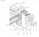
Fig. 4] Fig. 4 is a perspective view of the above cut-and-clinch apparatus. - [
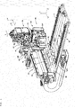
Fig. 5] Fig. 5 is a perspective view illustrating main parts of the above cut-and-clinch apparatus. - [
Fig. 6] Fig. 6 is a partial sectional view of a cut-and-clinch unit included in the above cut-and-clinch apparatus. - [
Fig. 7] Fig. 7 is a block diagram conceptually illustrating a control device of the above lead component mounting machine. - [
Fig. 8] Fig. 8(a) and Fig. 8(b) are operation views (a view illustrating a state where lead wires are cut and bent) of the above cut-and-clinch unit. - [
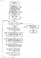
Fig. 9] Fig. 9 is a flowchart illustrating a deviation amount acquisition program stored in a memory section of the control device of the above cut-and-clinch apparatus. - [
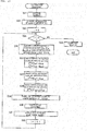
Fig. 10] Fig. 10 is a flowchart illustrating a cut-and-clinch program stored in the above memory section. - [
Fig. 11] Fig. 11 is a view illustrating changes in the amount of deviation amount accompanying changes in setting pitches acquired by execution of the above deviation amount acquisition program. (a) Pitch deviation amount, (b) Axis deviation angle, (c) Central point deviation amount - [
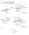
Fig. 12] Fig. 12 is a view conceptually illustrating the deviation amounts of actual positions of movable elements, which are acquired by the execution of the above deviation amount acquisition program, from target positions. - [
Fig. 13] Fig. 13 is a view illustrating a relative positional relationship between the coordinate axes of the above lead component mounting machine and the coordinate axes of the cut-and-clinch unit. - [
Fig. 14] Fig. 14 is a view illustrating a relationship between an actual position and a target position of the above cut-and-clinch unit. (a) a case of 0 < θ < 90°, (b) a case of θ = 0 - Hereinafter, an embodiment of the invention will be described, referring to the drawings. In addition, the invention can be implemented in various forms in which various changes and improvements are made on the basis of the knowledge of a person's skilled in the art, in addition to the following embodiment.
- As illustrated in
Fig. 1 , a lead component mounting machine that is a type of an automated assembly apparatus (electronic circuit assembly apparatus) includes (a) an assembly apparatusmain body 10, (b) aboard conveyance device 12, (c) acomponent supply device 14, (d) acomponent insertion device 16, and (e) a cut-and-clinch apparatus 18, and the like. - The
board conveyance device 12 conveys and holds a circuit board P (hereinafter called a board P for short) in a horizontal posture. InFig. 1 , x represents a conveyance direction of the board P by theboard conveyance device 12, y represents a width direction of the board P, and z represents a thickness direction of the board P, that is, an upward-downward direction of the lead component mounting machine. The x-direction, the y direction, and the z direction are orthogonal to each other. - The
component supply device 14 supplies components to be mounted on the board P, and can be, for example, a component supply device including a plurality of tape feeders or including a plurality of trays. In the present embodiment, lead components that are components including lead wires are supplied. - The
component insertion device 16 receives lead components supplied from thecomponent supply device 14, and inserts these components into through-holes provided at predetermined positions on the board P held by theboard conveyance device 12. Thecomponent insertion device 16 is provided above theboard conveyance device 12, and as illustrated inFig. 2 , includes twowork heads head moving device 22. The workhead moving device 22 includes anx-direction moving device 24, a y-direction moving device 25, and z-direction moving devices work heads x-direction moving device 24 and the y-direction moving device 25, and can be separately and independently moved in the z direction by the z-direction moving devices work head 20 of the two work heads includes a component holding tool 28 (for example, can be a chuck, a suction nozzle, or the like) that holds lead components. Acamera 30 is provided in order to image a reference position mark (fiducial mark) on the board P, and is provided so as to be movable integrally with thework head 20. In the present embodiment, thecamera 30 is fixedly attached to a z slider to which thework head 20 is detachably attached. - The cut-and-
clinch apparatus 18 is provided below theboard conveyance device 12, and is a device that cuts a portion, which protrudes from below the board P in a lead wire of a lead component inserted from above into a through-hole formed in the board P, with a predetermined length, and bending the portion along a back surface of the board P, thereby clinching the lead component to the board P. The cut-and-clinch apparatus 18, as illustrated inFigs. 3 to 6 , includes a cut-and-clinch unit 34, and aunit moving device 36 that moves (including linear movement and rotation) the cut-and-clinch unit 34. - The cut-and-
clinch unit 34 includes (a) a unit main body 38, (b) a pair of firstmovable sections movable sections movable sections pitch changing device 44 that is provided in the unit main body 38 and causes the pair of firstmovable sections movable sections - The
pitch changing device 44 includes (1) one pitch changing motor 46 (hereinafter called a P motor for short) that is a driving source, (2) amotion conversion mechanism 47 that converts the rotation of theP motor 46 into linear movement to linearly move the pair of firstmovable sections first guide rail 48 that is provided to extend in a direction horizontal to the unit main body 38, and the like. Themotion conversion mechanism 47 includes (i) amale screw member 52 coaxially including a right-hand screw part 50 and a left-hand screw part 51, and (ii) a pair ofnuts hand screw part 50 and the left-hand screw part 51, respectively. First movable sectionmain bodies first guide rail 48 are integrally movably held by thenuts pitch changing motor 46 causes the pair of firstmovable sections movable sections - As illustrated in
Fig. 6 , the pair of secondmovable sections main bodies section moving devices 56a and 56b so as to be individually relatively movable in the horizontal direction. The second movablesection moving devices 56a and 56b include (a)air cylinders 60a and 60b serving as second movable section driving sources that are fixedly provided in the first movable sectionmain bodies motion conversion mechanisms 62a and 62b that converts the movement of output shafts of theair cylinders 60a and 60b in the z direction into movement in the horizontal direction to move the secondmovable sections second guide grooves 63a and 63b that are respectively provided in the first movable sectionmain bodies motion conversion mechanisms 62a and 62b include a cam mechanism, includecams 64a and 64b that are provided in the first movable sectionmain bodies 54a and 54 and have inclined cam grooves formed therein, androllers 65a and 65b serving as cam followers that are respectively engaged with thecam grooves 64a and 64b, and second movable sectionmain bodies 66a and 66b having engaging sections engaged with thesecond guide grooves 63a and 63b are integrally movably held therollers 65a and 65b. In the present embodiment, thecams 64a and 64b are lifted and forward with lifting and lowering of the output shafts by the operation of theair cylinders 60a and 60b, and the secondmovable sections - The first
movable sections wire insertion holes wire insertion holes movable sections stationary blades movable sections movable sections wire guide holes wire insertion holes wire guide holes movable blades - In the present embodiment, the first
movable sections movable sections wire insertion hole movable elements 80a and 80b. Additionally, since the firstmovable sections movable sections pitch changing device 44, it is also possible to consider that movable elements are constituted of the firstmovable sections movable sections wire guide holes - The
unit moving device 36 includes anx-direction moving device 86 that moves the cut-and-clinch unit 34 in the x-direction, a y-direction moving device 87 that moves the cut-and-clinch unit 34 in the y direction, the z-direction moving device 88 that moves the cut-and-clinch unit 34 in the z direction, a θ-rotation device 89 that rotates the cut-and-clinch unit 34 around a plumb line, and the like. - As illustrated in
Figs. 3 and4 , the x-direction movingdevice 86 includes (1) an x-axis motor 90 (refer toFig. 7 ), (2) anx-axis guide 91 that extends in the x-axis direction, (3) aball screw mechanism 92 that converts the rotation of thex-axis motor 90 into linear movement, (4) anx slider 93 that is held by anut 92N of theball screw mechanisms 92 and is engaged with both thex-axis guide 91, and the like. - The y-
direction moving device 87 is provided in thex slider 93, and includes (1) a y-axis motor 94, (2) a y-axis guide 95 that extends in the y-direction, (3) aball screw mechanism 96, (4)a y slider 97 that is held by anut 96N of theball screw mechanisms 96 and is engaged with the y-axis guide 95, and the like. - The z-
direction moving device 88 is provided in they slider 97, and includes (1) a z-axis motor 100, (2) aguide 101 that extends in the z direction, (3) aball screw mechanisms 102, (4)a z slider 103 that is held by a nut of theball screw mechanisms 102 and is engaged with theguide 101, and the like. Thez slider 103 also has a function as a unit support member that supports the cut-and-clinch unit 34. - The θ-
rotation device 89 is provided in the z slider (unit support member) 103, include (1) a drivingmotor 104 that rotates the cut-and-clinch unit 34 around a plumb line, and (2) a rotary table 106 that is rotated around the plumb line with the rotation of (hereinafter called theθ motor 104 for short) of theθ motor 104, and the unit main body 38 is integrally rotatably provided in the rotary table 106. - In the present embodiment, in a case where θ is 0, a coordinate system (xc, yc, and zc) of the cut-and-
clinch unit 34 and a coordinate system (x, y, and z) of the lead component mounting machine coincide with each other. However, by rotating the cut-and-clinch unit 34 around the plumb line using the 0-rotation device 89, the coordinate system (xc, yc, and zc) is rotated with respect to the coordinate system (x, y, and z) around the z-axis. Hereinafter, in a case where the coordinate system of the cut-and-clinch unit 34 is represented, this coordinate system is distinguished from the coordinate system of the lead component mounting machine by attaching suffix c. - Additionally, in the coordinate system of the cut-and-
clinch unit 34, a movement direction (approach and separation direction) of the firstmovable sections movable elements 80a and 80b are located on an xc axis. - The overall lead component mounting machine is controlled by a
main control device 140 having a computer as a main constituent. A componentsupply control section 142, a board conveyance control section 144, a componentinsertion control section 146, a cut-and-clinch control section 148, and the like that have a computer as a main constituent are connected to themain control device 140 so as to be communicable with each other. Thecontrol sections component supply device 14,board conveyance device 12,component insertion device 16, and cut-and-clinch apparatus 18, respectively. Additionally, theP motor 46, thex-axis motor 90, the y-axis motor 94, the z-axis motor 100, theθ motor 104, and the like are connects to the cut-and-clinch control section 148 via a drive circuit (not illustrated). - In addition, in the lead component mounting machine, it is not indispensable that the control sections are provided for respective devices, such as the
component supply device 14, and the configuration of the control device is not limited to that in the present embodiment, like all the devices can be controlled on the basis of a command of themain control device 140. - In the present lead component mounting machine, as illustrated in
Fig. 8(a) and Fig. 8(b) , a lead component A including two lead wires La and Lb is mounted at a predetermined position on the board P conveyed by theboard conveyance device 12. - The lead component A supplied by the
component supply device 14 is gripped by the work heads 20 and 21 of thecomponent insertion device 16, and is placed on the board P by inserting the lead wires La and Lb through through-holes clinch apparatus 18, the cut-and-clinch unit 34 is moved in the x and y directions, and is rotated around the plumb line so as to reach positions (positions corresponding to the lead wires La and Lb) where the leadwire insertion holes holes movable elements 80a and 80b are made to approach each other and separate from each other such that the pitch between the pair of leadwire insertion holes holes - The lead wires La and Lb, as illustrated in
Fig. 8(a) , reach the leadwire insertion holes holes wire guide holes Fig. 8 (b) , the lead wires La and Lb are cut and bent by the secondmovable sections movable sections Fig. 6 ) attached to a main body 38 through a passage. - However, due to a problem of the machining accuracy of the
male screw member 52, an installation error of theguide 48, or the like, the positions of the leadwire insertion holes wire insertion holes holes - For example, as illustrated in
Fig. 14 (a) , in a case where the lead wires La and Lb of the lead component A are inserted into the through-holes clinch unit 34 is controlled in a posture indicated by a solid line. Specifically, a central point C (refer toFig. 5 , the same as a central point between central points of the leadwire insertion holes movable elements 80a and 80b is moved in the horizontal direction so as to reach a target central point Cref, and is rotated around the plumb line such that an axis α, which is a straight line which passes through the pair ofmovable elements 80a and 80b, become parallel to a target axis αref. Additionally, the pitch between the pair ofmovable elements 80a and 80b is changed so as to become a target pitch Pref. However, practically, the central point may be moved to a position indicated by a dashed line and be located at C*, an actual pitch may become P*, the axis may become α*, the pair ofmovable elements 80a and 80b may be located at Q1 and Q2 and may deviate from the target positions R1 and 2. - In addition, in a case where the mounting of the lead component A is performed, the target central point Cref, the target axis αref, and the target pitch Pref are determined depending on the mounting position or posture of the lead component A to the board P, the spacing between the lead wires, or the like. However, as will be described below, in a case where the mounting of the lead component A is not performed, and in a case where it is assumed that there are no errors or the like, the target central point Cref, the target axis αref, and the target pitch Pref mean positions and values. For example, in a case where it is assumed that the
movable elements 80a and 80b are moved according to control instruction values, the positions of themovable elements 80a and 80b are referred to as target positions, and the position of the central point thereof is referred to as a target central point. - Additionally, hereinafter, the positions of the
movable elements 80a and 80b mean the positions of the central points of the leadwire insertion holes movable elements 80a and 80b means a central point between the central points of the leadwire insertion holes - Moreover, in
Fig. 12(a) to Fig. 12(d) ,Fig. 14 (a) and Fig. 14 (b) , in order to make the invention easily understood, deviation is written largely, but actual deviation is slight. - Meanwhile, in a case where the
x-axis motor 90, the y-axis motor 94, and theθ motor 104 are in a non-operated state and only theP motor 46 is operated, and in a case where it is assumed that there are no errors, the pair ofmovable elements 80a and 80b should be made to linearly approach each other separate from each other on the xc axis. The central point C should always be at the same point, and the axis α should coincide with the xc axis. However, practically, as illustrated inFig. 12(a) to Fig. 12(d) , respective actual positions (indicated by thick-line circles) of the pair ofmovable elements 80a and 80b may deviate from target positions (indicated by triple circles). Additionally, with the deviation of the pair ofmovable elements 80a and 80b, as illustrated inFig. 12 (b) and Fig. 12(d) , an actual central point C* of themovable elements 80a and 80b may deviate from the target central point Cref, an actual axis α* may also incline with respect to the xc axis, and an actual pitch P* may also have a magnitude that is different from the target pitch Pref according to a control instruction value of theP motor 46. - In contrast, in a case where the
pitch changing device 44 individually has one driving source corresponding to each of the firstmovable sections movable elements 80a and 80b pass), it is possible to bring the central point C close to the target central point Cref through the control of the individual driving sources . However, in a case where the number of driving sources is one for the pair ofmovable elements - Thus, in the present embodiment, in a case where the mounting of the lead components onto the board P is not performed, in other words, in a state where the board P is not conveyed, the actual deviation amounts of the respective positions the
movable elements 80a and 80b from the target positions are acquired while changing the target pitch Pref and changing the control instruction value of theP motor 46. Then, (x) a deviation amount (central point deviation amount) of the actual central point C* from the target central point Cref, (y) an angle deviation (axis deviation angle) between the axis α* which actually pass through themovable elements 80a and 80b and the target axis αref, and (z) a deviation amount (pitch deviation amount) between the actual pitch P* and the target pitch Pref of themovable elements 80a and 80b are acquired using the acquired actual deviation amounts of the respective positions of themovable elements 80a and 80b are used, and the relationships between these deviation amounts and the target pitch (or a control instruction value) are stored as a table (hereinafter, a table showing these relationships is referred to as a deviation table) . Then, a correction value is acquired on the basis of a deviation amount acquired from the deviation table, and control instruction values for thex-axis motor 90, the y-axis motor 94, theP motor 46, the 0motor 104, and the like are generated on the basis of the correction value. Hereinafter, target pitches that are changed when acquiring the deviation table are referred to as setting pitches. The target pitches are distinguished from target pitches in actual control. - In addition, it is not indispensable to acquire deviation amounts between actual positions and target positions, and only the actual positions of the two
movable elements 80a and 80b may be acquired. This is because the target positions are known. - Deviation amounts between actual positions and target positions of the
movable elements 80a and 80b are acquired by the execution of a deviation acquisition program expressed by a flowchart ofFig. 9 , and a deviation table is acquired. In the present program, setting pitches P are stepwisely changed for every ΔP between an initial value P0 and final values P(n). - In Step 1 (hereinafter called S1 for short, the same applies to other Steps) and Step S2, the cut-and-
clinch unit 34 is horizontally moved to a predetermined measurement position by theunit moving device 36, and is rotated around the plumb line such that the coordinate system (xc, yc, and zc) of the cut-and-clinch unit 34 coincides with the coordinate system (x, y, and z) of the lead component mounting machine. In S3, a setting pitch P(j) is set to the initial value P0 (j = 0). In S4, it is determined whether or not the setting pitches P(j) {= P0 + j•ΔP: j = 0 to n} are equal to or lower than final values P(n) {= P0 + n•ΔP}. Since determination is YES in a case where S4 is executed first, in S5, a control instruction value is created according to the setting pitch P0, and theP motor 46 is controlled. In that state, in S6 and S7, image data is obtained by actually imaging the pair ofmovable elements 80a and 80b, respectively, using thecamera 30. Then, on the basis of the obtained image data, deviation amounts of respective actual positions of themovable elements 80a and 80b from target positions are acquired, and in S8, these deviation amounts are matched with the setting pitch P0, and are stored. - In detail, "imaging commands of the
movable elements 80a and 80b" are output from the cut-and-clinch control section 148. In thecomponent insertion device 16, thework head 20 is moved at a first position (a position where themover 80a that is one of themovable elements 80a and 80b can be imaged), and the onemover 80a is actually imaged by thecamera 30. Thereafter, thework head 20 is moves to a second position (a position where the other mover 80b can be imaged), and the other movable element 80b is actually imaged. Then, the obtained image data is output from the componentinsertion control section 146, and is received in the cut-and-clinch control section 148. In the cut-and-clinch control section 148, the positions of themovable elements 80a and 80b on actual (xc, yc) coordinates are acquired, and the deviation amounts of the movable elements from the target positions are acquired. For example, in a case illustrated inFig. 12(a) , the deviation amounts {an x component and a y component on the coordinates (xc, yc) } of the actual positions of themovable elements 80a and 80b from the target positions are acquired as shown in the following Expression with respect to themovable elements 80a and 80b, respectively.

- Then, the setting pitch is changed by ΔP in S9, j is increased by 1 in S10, and it is determined in S4 whether or not the setting pitch P(1) is equal to or lower than the final value P(n). In this case, since determination is YES, S5 to S10 are repeatedly executed. Hereinafter, while the setting pitches P(j) are equal to or lower than the final values P(n), S5 to S10 are repeatedly executed, and whenever the setting pitches P(j) are changed by every ΔP, the deviation amounts between the target positions and the respective actual positions of the
movable elements 80a and 80b are acquired. Meanwhile, if the setting pitches P(j) become greater than the final values P(n), determination of S4 becomes NO, and in S11, a deviation table is created. - In S11, (x) pitch deviation amounts dp(j), (y) axis deviation angles dθ(j), and (z) central point deviation amounts dC(j) are acquired on the basis of the acquired deviation amounts b{da(j), db(j)} of the respective position of the
movable elements 80a and 80b, are matched with the setting pitches P(j), and are stored. For example, in a case illustrated inFig. 12(b) , a pitch deviation amount dp(k-1), a central point deviation amount dC(k-1) = {dx0(k-1), dy0(k-1)}, and an axis deviation angle dθ(k-1) are acquired, are matched with a setting pitch P(k-1), and are stored, and in a case illustrated inFig. 12(d) , a pitch deviation amount dp(k+1), a central point deviation amount dC(k+1) = {dx0(k+1), dy0(k+1)}, and an axis deviation angle dθ(k+1) are acquired, are matched with the setting pitch P(k+1), and are stored. - An example of the deviation table that is the relationship between the setting pitches P(j) acquired as described above, and the pitch deviation amounts dp(j), the axis deviation angles dθ(j), and the central point deviation amounts dC(j) is illustrated in
Fig. 11(a), Fig. 11(b), and Fig. 11(c) . It is desirable that the deviation table is acquired in advance and is stored in the memory section of the cut-and-clinch control device 148. - In addition, ΔP may be a positive value or may be a negative value, and may be gradually increased or may be gradually decreased.
- Additionally, it is not indispensable to create the deviation table in advance and store the deviation table . This is because the pitch deviation amount dp, the axis deviation angle dθ, and the central point deviation amount dC can be acquired each time if the relationship between the setting pitches P(j) and the deviation amounts of the actual positions of the pair of
movable elements 80a and 80b from the target positions is known. - The lead wires La and Lb of the lead component A are cut and clinched by the execution of the cut-and-clinch program expressed by a flowchart of
Fig. 10 . - A board P is carried in S21, and information on each of a plurality of (m) lead components A(i) (i = 0 to m-1) to be inserted into the board P is acquired in S22. Specifically, regarding the respective lead components A(i), target central points Cref(i){xref(i), yref(i)} determined by positions where the lead components A(i)are mounted on the board, target pitches Pref (i) determined by the pitch between two lead wires La(i) and Lb(i), and target rotational angles θref(i) determined by the posture of the lead components A(i) mounted on the board P are respectively acquired. In S23, the number i of the lead components A(i)is set to 0 (i = 0), and information determined by the lead component A(0) is read. In S24, it is determined whether or not the number i of the lead component A is smaller than m. Since determination is YES in a case where S24 is first executed, in S25, a deviation in the case of a target pitch Pref(0) is acquired on the basis of the target pitch Pref(0) and the deviation table, and correction values are obtained regarding the
x-axis motor 90, the y-axis motor 96, theP motor 46, and theθ motor 104. Then, in S26 to S28, control instruction values are created on the basis of the correction values, and control is performed accordingly. - In S25, the pitch deviation amount dp, the axis deviation angle dθ, and the central point deviation amount dC in a case where a target pitch is Pref (0) are acquired by an interpolation method on the basis of the deviation table. In addition, here, generally, a case where the target pitches are Pref(i) will be described.
- (1) Regarding the target pitches Pref(i), two setting pitches P(k-1)and P(k) that satisfy
Expression 1 are acquired on the basis of the deviation table ofFig. 11(a) .
- (2) Then, from the deviation table of
Fig. 11(a), Fig. 11(b), and Fig. 11(c) , a pitch deviation amount dp(k-1), an axis deviation angle dθ(k-1), and a central point deviation amount {dx0(k-1), dy0(k-1)} stored in relation to the setting pitch P(k-1), respectively, are acquired and a pitch deviation amount dp(k), an axis deviation angle dθ(k), and a central point deviation amount {dx0(k), dy0(k)} stored in relation to the setting pitch P(k) are acquired. - (3) By the interpolation method, pitch deviation amounts dPref, axis deviation angles dθref, and central point deviation amounts (dxref', dyref') in the case of the target pitches Pref(i) are acquired.


- (4) Regarding the central point deviation amounts, a relative positional relationship between the coordinate system (x, y) of the unit moving device 36 (lead component mounting machine) and the coordinate system (xc, yc) of the cut-and-
clinch unit 34 is further taken into consideration. Although the central point deviation amounts are caused due to errors or the like in the cut-and-clinch unit 34, the deviation amounts are corrected by the control of theunit moving device 36. Therefore, the values of the central point deviation amounts caused in the coordinate system of the cut-and-clinch unit 34 in the coordinate system of the unit moving device 36 (the coordinate system of the lead component mounting machine) are acquired by coordinate conversion. For example, as illustrated inFig. 13 , in a case where the cut-and-clinch unit 34 is rotated by θref(i), a central point deviation amount (dxref', dyref') in the cut-and-clinch unit 34 has values shown in Expressions 2 and 3 in the coordinate system of the unit moving device 36 (where β = θref(i)).

- The deviation amount acquired as described above, as illustrated in
Fig. 14(a) and Fig. 14(b) , is a difference between a position (a position when being moved according to a control instruction value in a case where it is assumed that there is no deviation or the like) indicated by a solid line in the cut-and-clinch unit 34, and a position (actual position) indicated by a dashed line, and corresponds to a correction value of the control instruction value for performing a control such that the cut-and-clinch unit 34 approaches the position indicated by the solid line. - In S26 to 28, control instruction values to the
x-axis motor 90, the y-axis motor 94, theθ motor 104, and theP motor 46 are created, and control is performed accordingly. The control instruction value x*, y*, θ*, and P*, as illustrated inExpressions 4 to 7, are values obtained by subtracting the correction values dxref, dyref, dθref, and dPref from the control instruction values xref, yref, θref, and Pref in a case where it is assumed that there is no deviation.


- Since θref(i) is 0 in a case illustrated in
Fig. 14(b) , a control instruction value to theθ motor 104 becomes (-dθref), and correction values for thex-axis motor 90 and the y-axis motor 94 become dxref (= dxref') and dyref (= dyref'). - In addition, in the present embodiment, a target movement amount (rotational amount) is described as a control instruction value. However, in actual control, the amount of supply current determined on the basis of the target movement distance, or the like may be used as the control instruction value.
- The cut-and-
clinch unit 34 is moved to substantially a target position by the execution of S25 to S28. For example, in the case ofFig. 14 (a) and Fig. (b), the cut-and-clinch unit is moved to substantially the position indicated by the solid line. In S29, the cut-and-clinch unit 34 is lifted to a height where the openings of the leadwire guide holes holes wire insertion holes holes movable sections movable sections - Thereafter, in S31, the cut-and-
clinch unit 34 is lowered until the cut-and-clinch unit 34 is separated from the board P, and in S32, returns to S24 after the number of lead components A is increased by one. Hereinafter, the plurality of lead components A (i) are inserted, and the lead wires La and Lb are cut and clinched by S24 to S32 being repeatedly executed. Then, after all of m lead components A are mounted, determination of S24 becomes NO, and in S33, the board P is carried out. - In this way, in the present embodiment, the deviation table is created in advance and is stored. Then, in a case where cutting and clinching is actually performed, correction values are created by the interpolation method on the basis of the target pitches Pref(i) and the deviation table, and control instruction values for the
x-axis motor 90, the y-axis motor 96, theθ motor 104, and theP motor 46 are created. As a result, it is possible to favorably bring the actual positions of the pair ofmovable elements 80a and 80b close to target positions, and the positional accuracy of themovable elements 80a and 80b can be improved. As a result, the lead wires La and Lb of the lead component A can be accurately inserted into the leadwire insertion holes - Additionally, in a case where the spacing ΔP of the setting pitch of S9 is made small, a more detailed deviation table can be acquired as compared to a case where the spacing is made large. Accurate correction values can be created by creating control instruction values on the basis of the deviation table, and the
x-axis motor 90, the y-axis motor 94, theθ motor 104, and thepitch motor 46 can be accurately controlled. As a result, the positional accuracy of themovable elements 80a and 80b can be further improved. - Moreover, the central point of the pair of second
movable sections movable sections - In the present embodiment, a unit horizontal movement device is constituted of the
x-axis moving device 86, the y-axis movingdevice 87, and the like, and a unit rotation device is constituted of the θ-rotation device 89. Additionally, a movable element position control section is constituted of the deviation amount acquisition program of the cut-and-clinch control section 148 expressed by the flowchart ofFig. 9 , portions that store and execute the cut-and-clinch program expressed by the flowchart ofFig. 10 , a portion that stores the deviation table conceptually illustrated inFig. 11(a) to Fig. 11(c) , and the like. Additionally, a horizontal movement control section is constituted of a portion of the movable element position control section that stores and executes S25 and S26, and the like, and a rotation control section is constituted of a portion that stores and executes S25 and S28, and the like. Moreover, a central point deviation amount acquisition section and a deviation angle acquisition section are acquired by sections of the movable element position control section that store and execute S25, a section that stores the deviation table, and the like. In addition, a position correcting section is constituted of a section that stores and executes S25, and S26 to S28, and the like. Additionally, an actual position acquisition section is acquired portions of the movable element position control section that stores and executes S1 and S7, and the like, and an actual central point acquisition section is constituted of portions that store and execute S11, and the like. - In addition, it is not indispensable to use the interpolation method, and only the value of P(k) closet to Pref(i) may be used from the deviation table. Additionally, correction values can be acquired on the basis of one or two of pitch deviation amounts, axis deviation angles, and central point deviation amounts. Moreover, depending on the capability of a camera, both the pair of
movable elements 80a and 80b may be able to be imaged at once without moving the camera. - Additionally, the invention can be widely applied to the position control of a pair of movable elements that can approach each other and separate from each other, as well as the cut-and-clinch unit.
- 18: cut-and-clinch apparatus, 34: cut-and-clinch unit, 36: unit moving device, 40: first movable section, 42: second movable section, 44: pitch changing device, 68: lead wire insertion hole, 72: movable element, 86: x-axis moving device, 87: y-axis moving device, 88: z-axis moving device, 89: θ-rotation device, 170: through-hole
Claims (5)
- A cut-and-clinch apparatus (18) that is configured to cut and bend protruding parts of two lead wires (La, Lb) of a lead component (A) to be respectively inserted through two of a plurality of through-holes (170a, 170b) formed in a circuit board (P), the cut-and-clinch apparatus (18) comprising:a pair of movable elements (80a, 80b) that are configured to be used in a case where the respective protruding parts of the two lead wires (La, Lb) are cut and bent and that are configured to be made to approach each other and separate from each other; anda movable element position control section that is configured to control the positions of the pair of movable elements (80a, 80b), on the basis of image data obtained by imaging the pair of movable elements (80a, 80b), wherein the pair of movable elements (80a, 80b) are configured to be made to approach each other and separate from each other by one driving source.
- The cut-and-clinch apparatus (18) according to Claim 1, further comprising:(a) a cut-and-clinch unit (34) including the pair of movable elements (80a, 80b); and(b) a unit horizontal movement device (86, 87) that is configured to horizontally move the cut-and-clinch unit (34),
wherein the movable element position control section includes(i) a central point deviation amount acquisition section that is configured to acquire a central point deviation amount that is a deviation amount between a target central point and an actual central point of the pair of movable elements (80a, 80b) acquired on the basis of the image data, and(ii) a horizontal movement control section that is configured to control the unit horizontal movement device (86, 87) on the basis of the central point deviation amount acquired by the central point deviation amount acquisition section, to bring the actual central point of the pair of movable elements (80a, 80b) close to the target central point. - The cut-and-clinch apparatus (18) according to Claim 1 or 2, further comprising:(a) a cut-and-clinch unit (34) including the pair of movable elements (80a, 80b); and(b) a unit rotation device (89) that is configured to rotate the cut-and-clinch unit (34) around a plumb line,
wherein the movable element position control section includes(i) an axis deviation angle acquisition section that is configured to acquire an axis deviation angle that is an angle deviation between a target axis, and an axis that is acquired on the basis of the image data and actually passes through the pair of movable elements (80a, 80b), and(ii) a rotation control section that is configured to control the unit rotation device (89) on the basis of the axis deviation angle acquired by the axis deviation angle acquisition section to bring the axis that actually passes through the pair of movable elements (80a, 80b) close to a posture parallel to the target axis. - The cut-and-clinch apparatus (18) according to any one of Claims 1 to 3,
wherein the movable element position control section includes(i) an actual position acquisition section that is configured to acquire respective actual positions of the pair of movable elements on the basis of the image data, and(ii) a position correcting section that is configured to correct the positions of the pair of movable elements (80a, 80b) on the basis of one or more of (x) a central point deviation amount that is a deviation amount between a target central point and an actual central point of the pair of movable element, (y) an axis deviation angle that is an angle deviation between a target axis and an axis that actually passes through the pair of movable elements (80a, 80b), and (z) a pitch deviation amount that is a deviation amount between a target pitch and an actual pitch of the pair of movable elements (80a, 80b), the central point deviation amount, the axis deviation angle, and the pitch deviation amount being acquired on the basis of the respective actual positions of the pair of movable elements acquired by the actual position acquisition section. - A board work machine including the cut-and-clinch apparatus (18) according to claim 1,
wherein the pair of movable elements (80a, 80b) are configured to be made to approach each other and separate from each other on the same straight line by the one driving source,
wherein the board work machine further comprises:an imaging device (30) that is configured to image each of the pair of movable elements (80a, 80b); an actual central point acquisition section that is configured to acquire an actual central point of the pair of movable elements (80a, 80b), on the basis of image data obtained by the pair of movable elements (80a, 80b) being imaged by the imaging device (30); anda movable element position control section that is configured to control the positions of the pair of movable elements (80a, 80b), on the basis of a central point deviation amount that is a deviation amount of the actual central point, which is acquired by the actual central point acquisition section, from the target central point.
Applications Claiming Priority (1)
| Application Number | Priority Date | Filing Date | Title |
|---|---|---|---|
| PCT/JP2014/059161 WO2015145730A1 (en) | 2014-03-28 | 2014-03-28 | Cut-and-clinch apparatus and substrate work machine |
Publications (3)
| Publication Number | Publication Date |
|---|---|
| EP3125663A1 EP3125663A1 (en) | 2017-02-01 |
| EP3125663A4 EP3125663A4 (en) | 2017-05-31 |
| EP3125663B1 true EP3125663B1 (en) | 2020-04-22 |
Family
ID=54194319
Family Applications (1)
| Application Number | Title | Priority Date | Filing Date |
|---|---|---|---|
| EP14886876.3A Active EP3125663B1 (en) | 2014-03-28 | 2014-03-28 | Cut-and-clinch apparatus and substrate work machine |
Country Status (5)
| Country | Link |
|---|---|
| US (1) | US10375869B2 (en) |
| EP (1) | EP3125663B1 (en) |
| JP (1) | JP6333957B2 (en) |
| CN (2) | CN106134308B (en) |
| WO (1) | WO2015145730A1 (en) |
Cited By (1)
| Publication number | Priority date | Publication date | Assignee | Title |
|---|---|---|---|---|
| EP3780930B1 (en) * | 2018-03-26 | 2026-04-08 | Fuji Corporation | Lead-cutting system, and lead component installation system |
Families Citing this family (18)
| Publication number | Priority date | Publication date | Assignee | Title |
|---|---|---|---|---|
| US10264720B1 (en) * | 2015-06-23 | 2019-04-16 | Flextronics Ap, Llc | Lead trimming module |
| US10820460B2 (en) * | 2015-10-06 | 2020-10-27 | Fuji Corporation | Cutting and bending device |
| JP6619019B2 (en) * | 2015-10-22 | 2019-12-11 | 株式会社Fuji | Anti-substrate working system and insertion method |
| WO2017081724A1 (en) * | 2015-11-09 | 2017-05-18 | 富士機械製造株式会社 | Bending apparatus |
| US20170238416A1 (en) | 2016-02-17 | 2017-08-17 | Multek Technologies Limited | Dummy core restrict resin process and structure |
| JP6596663B2 (en) * | 2016-03-02 | 2019-10-30 | パナソニックIpマネジメント株式会社 | Clinch mechanism and component mounting device |
| JP6603876B2 (en) * | 2016-03-02 | 2019-11-13 | パナソニックIpマネジメント株式会社 | Clinch mechanism and component mounting device |
| US9999134B2 (en) | 2016-03-14 | 2018-06-12 | Multek Technologies Limited | Self-decap cavity fabrication process and structure |
| JP7038041B2 (en) * | 2016-03-18 | 2022-03-17 | 株式会社Fuji | Parts mounting method and parts mounting line |
| WO2018016025A1 (en) * | 2016-07-20 | 2018-01-25 | 富士機械製造株式会社 | Substrate work machine |
| EP3500081B1 (en) * | 2016-08-11 | 2021-09-22 | Fuji Corporation | Substrate working machine |
| JP7142454B2 (en) * | 2018-04-13 | 2022-09-27 | Juki株式会社 | Mounting equipment, mounting method |
| JP7365616B2 (en) * | 2019-07-02 | 2023-10-20 | パナソニックIpマネジメント株式会社 | Component mounting device and method for manufacturing component mounting board using the same |
| CN110730612B (en) * | 2019-10-24 | 2021-06-29 | 冷晓勇 | Riveting foot mechanism |
| JP7010980B2 (en) * | 2020-01-22 | 2022-01-26 | 株式会社Fuji | Cutting / bending method |
| JP7242920B2 (en) * | 2020-01-22 | 2023-03-20 | 株式会社Fuji | Cutting/bending device |
| JP7145180B2 (en) * | 2020-04-06 | 2022-09-30 | 株式会社Fuji | Parts mounting machine |
| JP7411841B2 (en) * | 2022-01-13 | 2024-01-11 | 株式会社Fuji | Cutting/bending equipment |
Family Cites Families (36)
| Publication number | Priority date | Publication date | Assignee | Title |
|---|---|---|---|---|
| US3435857A (en) * | 1967-02-23 | 1969-04-01 | Universal Instruments Corp | Component lead clinching device |
| US3414024A (en) * | 1967-03-01 | 1968-12-03 | Western Electric Co | Apparatus for cutting and bending wire leads |
| US3986533A (en) * | 1975-11-26 | 1976-10-19 | Usm Corporation | Mechanism for clinching leads inwardly or outwardly |
| JPS5449567A (en) * | 1977-09-19 | 1979-04-18 | Matsushita Electric Industrial Co Ltd | Device for detecting insertion of electronic parts |
| JPS56118391A (en) * | 1980-02-25 | 1981-09-17 | Hitachi Ltd | Method and device for inserting electronic part |
| US4447945A (en) * | 1980-05-01 | 1984-05-15 | Contact Systems, Inc. | Cut and clinch mechanism for use in electrical component assembly apparatus |
| US4586237A (en) * | 1983-09-28 | 1986-05-06 | Usm Corporation | Drive mechanism for a cut and clinch unit |
| JPS6027495U (en) * | 1983-08-01 | 1985-02-25 | ティーディーケイ株式会社 | Lead wire cutting and bending mechanism |
| US4622740A (en) * | 1983-11-21 | 1986-11-18 | Usm Corporation | Electrical component lead sensor |
| US4584758A (en) * | 1984-09-04 | 1986-04-29 | Emhart Corporation | Cut-clinch mechanism |
| US4630354A (en) * | 1985-04-22 | 1986-12-23 | Theodore Staviski | Electrical component lead bending and cutting apparatus |
| US4705081A (en) * | 1986-02-21 | 1987-11-10 | Hewlett-Packard Company | System for sensing and forming objects such as leads of electronic components |
| JPH0695599B2 (en) * | 1988-08-26 | 1994-11-24 | 日本電装株式会社 | Electronic component fixing device |
| GB8923641D0 (en) | 1989-10-20 | 1989-12-06 | Blakell Systems Limited | Printed circuit board assembly apparatus |
| JPH0563396A (en) * | 1991-09-02 | 1993-03-12 | Tdk Corp | Method and apparatus for insertion of electronic component |
| ATE118151T1 (en) * | 1991-11-11 | 1995-02-15 | Siemens Ag | DEVICE FOR FASTENING COMPONENTS IN MULTI-POLE CIRCUIT BOARDS. |
| JPH05209703A (en) | 1992-01-31 | 1993-08-20 | Mitsubishi Heavy Ind Ltd | Gear tooth thickness measuring device |
| US5898983A (en) * | 1996-01-05 | 1999-05-04 | Tdk Corporation Of America | Electric component insertion apparatus |
| JP2000503471A (en) * | 1996-01-05 | 2000-03-21 | ティーディーケイ コーポレーション オブ アメリカ | Electric component insertion device |
| WO2000065895A1 (en) * | 1999-04-27 | 2000-11-02 | Matsushita Electric Industrial Co., Ltd. | Component mounting apparatus and device for detecting attachment of component on substrate |
| JP3646288B2 (en) * | 2000-03-30 | 2005-05-11 | Tdk株式会社 | Lead wire cut and clinching method and apparatus |
| JP3722694B2 (en) * | 2000-12-14 | 2005-11-30 | Tdk株式会社 | Electronic component lead wire cut and clinch method and electronic component insertion apparatus |
| JP2003174293A (en) * | 2001-12-04 | 2003-06-20 | Pentax Corp | Guide member and substrate mounting method for light emitting element |
| EP1536677A4 (en) * | 2002-07-19 | 2006-11-15 | Matsushita Electric Industrial Co Ltd | HEAD INSERTING HEAD DEVICE, WORK INSERTING DEVICE, AND WORK INSERTING METHOD |
| JP2005227365A (en) * | 2004-02-10 | 2005-08-25 | Sony Corp | Manufacturing method of optical components |
| US7148078B2 (en) * | 2004-02-23 | 2006-12-12 | Avago Technologies Egbu Ip (Singapore) Pte. Ltd. | Integrated circuit package provided with cooperatively arranged illumination and sensing capabilities |
| CN201327538Y (en) * | 2008-10-30 | 2009-10-14 | 群邦电子(苏州)有限公司 | Pin bending and cutting device for transmitter optical sub-assembly and receiver optical sub-assembly |
| CN100585441C (en) * | 2008-10-30 | 2010-01-27 | 群邦电子(苏州)有限公司 | Bending and cutting device for light-emitting components and light-receiving components |
| JP5930599B2 (en) * | 2011-04-05 | 2016-06-08 | 富士機械製造株式会社 | Electronic component mounting method and mounting device |
| KR102028743B1 (en) * | 2011-10-07 | 2019-10-04 | 쥬키 가부시키가이샤 | Electronic component mounting apparatus, and electronic component mounting method |
| JP5792588B2 (en) * | 2011-10-25 | 2015-10-14 | Juki株式会社 | Electronic component mounting equipment |
| JP2013251475A (en) * | 2012-06-04 | 2013-12-12 | Panasonic Corp | Calibration value obtaining method in electronic component mounting line and electronic component mounting method on electronic component mounting line |
| JP6027778B2 (en) * | 2012-06-11 | 2016-11-16 | ヤマハ発動機株式会社 | Component mounting device, component mounting method |
| JP5878082B2 (en) * | 2012-06-11 | 2016-03-08 | ヤマハ発動機株式会社 | Clinch device, component mounting device |
| JP5840076B2 (en) * | 2012-06-11 | 2016-01-06 | ヤマハ発動機株式会社 | Clinch device, component mounting device |
| CN104602872B (en) | 2012-09-04 | 2017-03-08 | 富士机械制造株式会社 | Operating device |
-
2014
- 2014-03-28 CN CN201480077587.4A patent/CN106134308B/en active Active
- 2014-03-28 US US15/129,355 patent/US10375869B2/en active Active
- 2014-03-28 WO PCT/JP2014/059161 patent/WO2015145730A1/en not_active Ceased
- 2014-03-28 CN CN201910812576.0A patent/CN110650620B/en active Active
- 2014-03-28 EP EP14886876.3A patent/EP3125663B1/en active Active
- 2014-03-28 JP JP2016509825A patent/JP6333957B2/en active Active
Non-Patent Citations (1)
| Title |
|---|
| None * |
Cited By (1)
| Publication number | Priority date | Publication date | Assignee | Title |
|---|---|---|---|---|
| EP3780930B1 (en) * | 2018-03-26 | 2026-04-08 | Fuji Corporation | Lead-cutting system, and lead component installation system |
Also Published As
| Publication number | Publication date |
|---|---|
| JP6333957B2 (en) | 2018-05-30 |
| EP3125663A4 (en) | 2017-05-31 |
| JPWO2015145730A1 (en) | 2017-04-13 |
| CN106134308B (en) | 2019-10-11 |
| CN110650620A (en) | 2020-01-03 |
| US20170118879A1 (en) | 2017-04-27 |
| US10375869B2 (en) | 2019-08-06 |
| EP3125663A1 (en) | 2017-02-01 |
| CN106134308A (en) | 2016-11-16 |
| WO2015145730A1 (en) | 2015-10-01 |
| CN110650620B (en) | 2021-05-28 |
Similar Documents
| Publication | Publication Date | Title |
|---|---|---|
| EP3125663A1 (en) | Cut-and-clinch apparatus and substrate work machine | |
| EP3367774B1 (en) | System for performing work on substrate and insertion method | |
| EP3379912B1 (en) | Substrate working machine and insertion method | |
| EP2894012A1 (en) | Work device | |
| EP3211983A1 (en) | Component adsorption position correction system and component adsorption position correction method for rotary head-type component mounter | |
| CN108029231B (en) | Substrate processing machine and recognition method | |
| JP6851227B2 (en) | Anti-board work machine | |
| JP6651538B2 (en) | Cutting and bending equipment | |
| JP2016004987A (en) | Electronic component packaging device, and electronic component packaging method | |
| JP6823006B2 (en) | Automatic assembly equipment, position control method | |
| JP6648132B2 (en) | Board work machine and recognition method | |
| JP2020025148A (en) | Automatic assembly device and position control method | |
| JP2017063118A (en) | Cut and clinch device and substrate work machine | |
| US11357146B2 (en) | Component mounting machine | |
| JP6554389B2 (en) | Board work system | |
| JP2020025149A (en) | Automated assembly equipment and position control method | |
| JP7242920B2 (en) | Cutting/bending device | |
| CN109565952B (en) | Substrate working machine | |
| JP7344368B2 (en) | Board-to-board working machine | |
| JP2023060222A (en) | Cutting/bending device |
Legal Events
| Date | Code | Title | Description |
|---|---|---|---|
| PUAI | Public reference made under article 153(3) epc to a published international application that has entered the european phase |
Free format text: ORIGINAL CODE: 0009012 |
|
| STAA | Information on the status of an ep patent application or granted ep patent |
Free format text: STATUS: REQUEST FOR EXAMINATION WAS MADE |
|
| 17P | Request for examination filed |
Effective date: 20160928 |
|
| AK | Designated contracting states |
Kind code of ref document: A1 Designated state(s): AL AT BE BG CH CY CZ DE DK EE ES FI FR GB GR HR HU IE IS IT LI LT LU LV MC MK MT NL NO PL PT RO RS SE SI SK SM TR |
|
| AX | Request for extension of the european patent |
Extension state: BA ME |
|
| A4 | Supplementary search report drawn up and despatched |
Effective date: 20170503 |
|
| RIC1 | Information provided on ipc code assigned before grant |
Ipc: H05K 13/04 20060101AFI20170425BHEP |
|
| DAX | Request for extension of the european patent (deleted) | ||
| STAA | Information on the status of an ep patent application or granted ep patent |
Free format text: STATUS: EXAMINATION IS IN PROGRESS |
|
| 17Q | First examination report despatched |
Effective date: 20180907 |
|
| RAP1 | Party data changed (applicant data changed or rights of an application transferred) |
Owner name: FUJI CORPORATION |
|
| RIN1 | Information on inventor provided before grant (corrected) |
Inventor name: MAEDA, HARUAKI Inventor name: NAKANISHI, YUSUKE |
|
| GRAP | Despatch of communication of intention to grant a patent |
Free format text: ORIGINAL CODE: EPIDOSNIGR1 |
|
| STAA | Information on the status of an ep patent application or granted ep patent |
Free format text: STATUS: GRANT OF PATENT IS INTENDED |
|
| INTG | Intention to grant announced |
Effective date: 20191212 |
|
| GRAS | Grant fee paid |
Free format text: ORIGINAL CODE: EPIDOSNIGR3 |
|
| GRAA | (expected) grant |
Free format text: ORIGINAL CODE: 0009210 |
|
| STAA | Information on the status of an ep patent application or granted ep patent |
Free format text: STATUS: THE PATENT HAS BEEN GRANTED |
|
| AK | Designated contracting states |
Kind code of ref document: B1 Designated state(s): AL AT BE BG CH CY CZ DE DK EE ES FI FR GB GR HR HU IE IS IT LI LT LU LV MC MK MT NL NO PL PT RO RS SE SI SK SM TR |
|
| REG | Reference to a national code |
Ref country code: CH Ref legal event code: EP |
|
| REG | Reference to a national code |
Ref country code: IE Ref legal event code: FG4D |
|
| REG | Reference to a national code |
Ref country code: DE Ref legal event code: R096 Ref document number: 602014064328 Country of ref document: DE |
|
| REG | Reference to a national code |
Ref country code: AT Ref legal event code: REF Ref document number: 1261926 Country of ref document: AT Kind code of ref document: T Effective date: 20200515 |
|
| REG | Reference to a national code |
Ref country code: LT Ref legal event code: MG4D |
|
| REG | Reference to a national code |
Ref country code: NL Ref legal event code: MP Effective date: 20200422 |
|
| PG25 | Lapsed in a contracting state [announced via postgrant information from national office to epo] |
Ref country code: IS Free format text: LAPSE BECAUSE OF FAILURE TO SUBMIT A TRANSLATION OF THE DESCRIPTION OR TO PAY THE FEE WITHIN THE PRESCRIBED TIME-LIMIT Effective date: 20200822 Ref country code: GR Free format text: LAPSE BECAUSE OF FAILURE TO SUBMIT A TRANSLATION OF THE DESCRIPTION OR TO PAY THE FEE WITHIN THE PRESCRIBED TIME-LIMIT Effective date: 20200723 Ref country code: PT Free format text: LAPSE BECAUSE OF FAILURE TO SUBMIT A TRANSLATION OF THE DESCRIPTION OR TO PAY THE FEE WITHIN THE PRESCRIBED TIME-LIMIT Effective date: 20200824 Ref country code: LT Free format text: LAPSE BECAUSE OF FAILURE TO SUBMIT A TRANSLATION OF THE DESCRIPTION OR TO PAY THE FEE WITHIN THE PRESCRIBED TIME-LIMIT Effective date: 20200422 Ref country code: NL Free format text: LAPSE BECAUSE OF FAILURE TO SUBMIT A TRANSLATION OF THE DESCRIPTION OR TO PAY THE FEE WITHIN THE PRESCRIBED TIME-LIMIT Effective date: 20200422 Ref country code: SE Free format text: LAPSE BECAUSE OF FAILURE TO SUBMIT A TRANSLATION OF THE DESCRIPTION OR TO PAY THE FEE WITHIN THE PRESCRIBED TIME-LIMIT Effective date: 20200422 Ref country code: NO Free format text: LAPSE BECAUSE OF FAILURE TO SUBMIT A TRANSLATION OF THE DESCRIPTION OR TO PAY THE FEE WITHIN THE PRESCRIBED TIME-LIMIT Effective date: 20200722 Ref country code: FI Free format text: LAPSE BECAUSE OF FAILURE TO SUBMIT A TRANSLATION OF THE DESCRIPTION OR TO PAY THE FEE WITHIN THE PRESCRIBED TIME-LIMIT Effective date: 20200422 |
|
| REG | Reference to a national code |
Ref country code: AT Ref legal event code: MK05 Ref document number: 1261926 Country of ref document: AT Kind code of ref document: T Effective date: 20200422 |
|
| PG25 | Lapsed in a contracting state [announced via postgrant information from national office to epo] |
Ref country code: BG Free format text: LAPSE BECAUSE OF FAILURE TO SUBMIT A TRANSLATION OF THE DESCRIPTION OR TO PAY THE FEE WITHIN THE PRESCRIBED TIME-LIMIT Effective date: 20200722 Ref country code: LV Free format text: LAPSE BECAUSE OF FAILURE TO SUBMIT A TRANSLATION OF THE DESCRIPTION OR TO PAY THE FEE WITHIN THE PRESCRIBED TIME-LIMIT Effective date: 20200422 Ref country code: HR Free format text: LAPSE BECAUSE OF FAILURE TO SUBMIT A TRANSLATION OF THE DESCRIPTION OR TO PAY THE FEE WITHIN THE PRESCRIBED TIME-LIMIT Effective date: 20200422 Ref country code: RS Free format text: LAPSE BECAUSE OF FAILURE TO SUBMIT A TRANSLATION OF THE DESCRIPTION OR TO PAY THE FEE WITHIN THE PRESCRIBED TIME-LIMIT Effective date: 20200422 |
|
| PG25 | Lapsed in a contracting state [announced via postgrant information from national office to epo] |
Ref country code: AL Free format text: LAPSE BECAUSE OF FAILURE TO SUBMIT A TRANSLATION OF THE DESCRIPTION OR TO PAY THE FEE WITHIN THE PRESCRIBED TIME-LIMIT Effective date: 20200422 |
|
| REG | Reference to a national code |
Ref country code: DE Ref legal event code: R097 Ref document number: 602014064328 Country of ref document: DE |
|
| PG25 | Lapsed in a contracting state [announced via postgrant information from national office to epo] |
Ref country code: AT Free format text: LAPSE BECAUSE OF FAILURE TO SUBMIT A TRANSLATION OF THE DESCRIPTION OR TO PAY THE FEE WITHIN THE PRESCRIBED TIME-LIMIT Effective date: 20200422 Ref country code: DK Free format text: LAPSE BECAUSE OF FAILURE TO SUBMIT A TRANSLATION OF THE DESCRIPTION OR TO PAY THE FEE WITHIN THE PRESCRIBED TIME-LIMIT Effective date: 20200422 Ref country code: EE Free format text: LAPSE BECAUSE OF FAILURE TO SUBMIT A TRANSLATION OF THE DESCRIPTION OR TO PAY THE FEE WITHIN THE PRESCRIBED TIME-LIMIT Effective date: 20200422 Ref country code: ES Free format text: LAPSE BECAUSE OF FAILURE TO SUBMIT A TRANSLATION OF THE DESCRIPTION OR TO PAY THE FEE WITHIN THE PRESCRIBED TIME-LIMIT Effective date: 20200422 Ref country code: CZ Free format text: LAPSE BECAUSE OF FAILURE TO SUBMIT A TRANSLATION OF THE DESCRIPTION OR TO PAY THE FEE WITHIN THE PRESCRIBED TIME-LIMIT Effective date: 20200422 Ref country code: RO Free format text: LAPSE BECAUSE OF FAILURE TO SUBMIT A TRANSLATION OF THE DESCRIPTION OR TO PAY THE FEE WITHIN THE PRESCRIBED TIME-LIMIT Effective date: 20200422 Ref country code: SM Free format text: LAPSE BECAUSE OF FAILURE TO SUBMIT A TRANSLATION OF THE DESCRIPTION OR TO PAY THE FEE WITHIN THE PRESCRIBED TIME-LIMIT Effective date: 20200422 |
|
| PG25 | Lapsed in a contracting state [announced via postgrant information from national office to epo] |
Ref country code: SK Free format text: LAPSE BECAUSE OF FAILURE TO SUBMIT A TRANSLATION OF THE DESCRIPTION OR TO PAY THE FEE WITHIN THE PRESCRIBED TIME-LIMIT Effective date: 20200422 Ref country code: PL Free format text: LAPSE BECAUSE OF FAILURE TO SUBMIT A TRANSLATION OF THE DESCRIPTION OR TO PAY THE FEE WITHIN THE PRESCRIBED TIME-LIMIT Effective date: 20200422 |
|
| PLBE | No opposition filed within time limit |
Free format text: ORIGINAL CODE: 0009261 |
|
| STAA | Information on the status of an ep patent application or granted ep patent |
Free format text: STATUS: NO OPPOSITION FILED WITHIN TIME LIMIT |
|
| 26N | No opposition filed |
Effective date: 20210125 |
|
| PG25 | Lapsed in a contracting state [announced via postgrant information from national office to epo] |
Ref country code: SI Free format text: LAPSE BECAUSE OF FAILURE TO SUBMIT A TRANSLATION OF THE DESCRIPTION OR TO PAY THE FEE WITHIN THE PRESCRIBED TIME-LIMIT Effective date: 20200422 |
|
| PG25 | Lapsed in a contracting state [announced via postgrant information from national office to epo] |
Ref country code: MC Free format text: LAPSE BECAUSE OF FAILURE TO SUBMIT A TRANSLATION OF THE DESCRIPTION OR TO PAY THE FEE WITHIN THE PRESCRIBED TIME-LIMIT Effective date: 20200422 |
|
| REG | Reference to a national code |
Ref country code: CH Ref legal event code: PL |
|
| GBPC | Gb: european patent ceased through non-payment of renewal fee |
Effective date: 20210328 |
|
| REG | Reference to a national code |
Ref country code: BE Ref legal event code: MM Effective date: 20210331 |
|
| PG25 | Lapsed in a contracting state [announced via postgrant information from national office to epo] |
Ref country code: CH Free format text: LAPSE BECAUSE OF NON-PAYMENT OF DUE FEES Effective date: 20210331 Ref country code: LI Free format text: LAPSE BECAUSE OF NON-PAYMENT OF DUE FEES Effective date: 20210331 Ref country code: LU Free format text: LAPSE BECAUSE OF NON-PAYMENT OF DUE FEES Effective date: 20210328 Ref country code: GB Free format text: LAPSE BECAUSE OF NON-PAYMENT OF DUE FEES Effective date: 20210328 Ref country code: FR Free format text: LAPSE BECAUSE OF NON-PAYMENT OF DUE FEES Effective date: 20210331 Ref country code: IE Free format text: LAPSE BECAUSE OF NON-PAYMENT OF DUE FEES Effective date: 20210328 |
|
| PG25 | Lapsed in a contracting state [announced via postgrant information from national office to epo] |
Ref country code: BE Free format text: LAPSE BECAUSE OF NON-PAYMENT OF DUE FEES Effective date: 20210331 |
|
| PG25 | Lapsed in a contracting state [announced via postgrant information from national office to epo] |
Ref country code: HU Free format text: LAPSE BECAUSE OF FAILURE TO SUBMIT A TRANSLATION OF THE DESCRIPTION OR TO PAY THE FEE WITHIN THE PRESCRIBED TIME-LIMIT; INVALID AB INITIO Effective date: 20140328 |
|
| P01 | Opt-out of the competence of the unified patent court (upc) registered |
Effective date: 20230328 |
|
| PG25 | Lapsed in a contracting state [announced via postgrant information from national office to epo] |
Ref country code: CY Free format text: LAPSE BECAUSE OF FAILURE TO SUBMIT A TRANSLATION OF THE DESCRIPTION OR TO PAY THE FEE WITHIN THE PRESCRIBED TIME-LIMIT Effective date: 20200422 |
|
| PG25 | Lapsed in a contracting state [announced via postgrant information from national office to epo] |
Ref country code: MK Free format text: LAPSE BECAUSE OF FAILURE TO SUBMIT A TRANSLATION OF THE DESCRIPTION OR TO PAY THE FEE WITHIN THE PRESCRIBED TIME-LIMIT Effective date: 20200422 |
|
| PG25 | Lapsed in a contracting state [announced via postgrant information from national office to epo] |
Ref country code: TR Free format text: LAPSE BECAUSE OF FAILURE TO SUBMIT A TRANSLATION OF THE DESCRIPTION OR TO PAY THE FEE WITHIN THE PRESCRIBED TIME-LIMIT Effective date: 20200422 |
|
| PG25 | Lapsed in a contracting state [announced via postgrant information from national office to epo] |
Ref country code: MT Free format text: LAPSE BECAUSE OF FAILURE TO SUBMIT A TRANSLATION OF THE DESCRIPTION OR TO PAY THE FEE WITHIN THE PRESCRIBED TIME-LIMIT Effective date: 20200422 |
|
| PGFP | Annual fee paid to national office [announced via postgrant information from national office to epo] |
Ref country code: DE Payment date: 20260204 Year of fee payment: 13 |
|
| PGFP | Annual fee paid to national office [announced via postgrant information from national office to epo] |
Ref country code: IT Payment date: 20260220 Year of fee payment: 13 |