EP3124712A1 - Compressible joint sealing strip and method for the production thereof - Google Patents
Compressible joint sealing strip and method for the production thereof Download PDFInfo
- Publication number
- EP3124712A1 EP3124712A1 EP15179048.2A EP15179048A EP3124712A1 EP 3124712 A1 EP3124712 A1 EP 3124712A1 EP 15179048 A EP15179048 A EP 15179048A EP 3124712 A1 EP3124712 A1 EP 3124712A1
- Authority
- EP
- European Patent Office
- Prior art keywords
- sealing strip
- joint sealing
- joint
- foam
- membrane layers
- Prior art date
- Legal status (The legal status is an assumption and is not a legal conclusion. Google has not performed a legal analysis and makes no representation as to the accuracy of the status listed.)
- Granted
Links
- 238000007789 sealing Methods 0.000 title claims abstract description 255
- 238000000034 method Methods 0.000 title claims description 15
- 238000004519 manufacturing process Methods 0.000 title claims description 13
- 239000010410 layer Substances 0.000 claims description 185
- 239000012528 membrane Substances 0.000 claims description 181
- 239000006260 foam Substances 0.000 claims description 137
- 239000000853 adhesive Substances 0.000 claims description 17
- 239000000463 material Substances 0.000 claims description 17
- 238000003475 lamination Methods 0.000 claims description 15
- 230000001070 adhesive effect Effects 0.000 claims description 13
- 239000012790 adhesive layer Substances 0.000 claims description 11
- 238000005096 rolling process Methods 0.000 claims description 11
- 238000000926 separation method Methods 0.000 claims description 10
- 238000004026 adhesive bonding Methods 0.000 claims description 5
- 229920001296 polysiloxane Polymers 0.000 claims description 5
- 238000010030 laminating Methods 0.000 claims description 4
- 238000005470 impregnation Methods 0.000 claims description 3
- 235000012431 wafers Nutrition 0.000 claims description 2
- 238000004804 winding Methods 0.000 claims 1
- XLYOFNOQVPJJNP-UHFFFAOYSA-N water Chemical compound O XLYOFNOQVPJJNP-UHFFFAOYSA-N 0.000 description 16
- 238000011161 development Methods 0.000 description 12
- 230000018109 developmental process Effects 0.000 description 12
- 238000009792 diffusion process Methods 0.000 description 12
- 238000009434 installation Methods 0.000 description 6
- 239000000203 mixture Substances 0.000 description 6
- 238000010276 construction Methods 0.000 description 4
- 239000004952 Polyamide Substances 0.000 description 3
- 229920002647 polyamide Polymers 0.000 description 3
- RNFJDJUURJAICM-UHFFFAOYSA-N 2,2,4,4,6,6-hexaphenoxy-1,3,5-triaza-2$l^{5},4$l^{5},6$l^{5}-triphosphacyclohexa-1,3,5-triene Chemical group N=1P(OC=2C=CC=CC=2)(OC=2C=CC=CC=2)=NP(OC=2C=CC=CC=2)(OC=2C=CC=CC=2)=NP=1(OC=1C=CC=CC=1)OC1=CC=CC=C1 RNFJDJUURJAICM-UHFFFAOYSA-N 0.000 description 2
- NIXOWILDQLNWCW-UHFFFAOYSA-M Acrylate Chemical compound [O-]C(=O)C=C NIXOWILDQLNWCW-UHFFFAOYSA-M 0.000 description 2
- 239000004820 Pressure-sensitive adhesive Substances 0.000 description 2
- 150000001252 acrylic acid derivatives Chemical class 0.000 description 2
- 230000004888 barrier function Effects 0.000 description 2
- 230000001419 dependent effect Effects 0.000 description 2
- 239000003063 flame retardant Substances 0.000 description 2
- 238000009413 insulation Methods 0.000 description 2
- 239000002346 layers by function Substances 0.000 description 2
- 230000035699 permeability Effects 0.000 description 2
- 239000004814 polyurethane Substances 0.000 description 2
- 238000011084 recovery Methods 0.000 description 2
- 238000009418 renovation Methods 0.000 description 2
- 239000000565 sealant Substances 0.000 description 2
- 229920005830 Polyurethane Foam Polymers 0.000 description 1
- 230000032683 aging Effects 0.000 description 1
- 230000006837 decompression Effects 0.000 description 1
- 230000007423 decrease Effects 0.000 description 1
- 230000018044 dehydration Effects 0.000 description 1
- 238000006297 dehydration reaction Methods 0.000 description 1
- 230000003111 delayed effect Effects 0.000 description 1
- 239000006185 dispersion Substances 0.000 description 1
- 230000000694 effects Effects 0.000 description 1
- 238000005516 engineering process Methods 0.000 description 1
- 229920002635 polyurethane Polymers 0.000 description 1
- 239000011496 polyurethane foam Substances 0.000 description 1
- 238000000275 quality assurance Methods 0.000 description 1
Images


Classifications
-
- E—FIXED CONSTRUCTIONS
- E04—BUILDING
- E04B—GENERAL BUILDING CONSTRUCTIONS; WALLS, e.g. PARTITIONS; ROOFS; FLOORS; CEILINGS; INSULATION OR OTHER PROTECTION OF BUILDINGS
- E04B1/00—Constructions in general; Structures which are not restricted either to walls, e.g. partitions, or floors or ceilings or roofs
- E04B1/62—Insulation or other protection; Elements or use of specified material therefor
- E04B1/66—Sealings
- E04B1/68—Sealings of joints, e.g. expansion joints
- E04B1/6812—Compressable seals of solid form
-
- E—FIXED CONSTRUCTIONS
- E06—DOORS, WINDOWS, SHUTTERS, OR ROLLER BLINDS IN GENERAL; LADDERS
- E06B—FIXED OR MOVABLE CLOSURES FOR OPENINGS IN BUILDINGS, VEHICLES, FENCES OR LIKE ENCLOSURES IN GENERAL, e.g. DOORS, WINDOWS, BLINDS, GATES
- E06B1/00—Border constructions of openings in walls, floors, or ceilings; Frames to be rigidly mounted in such openings
- E06B1/62—Tightening or covering joints between the border of openings and the frame or between contiguous frames
- E06B2001/626—Tightening or covering joints between the border of openings and the frame or between contiguous frames comprising expanding foam strips
Definitions
- the present invention relates to a compressible jointing tape according to the preamble of claim 1 and to a method for producing the same.
- Compressible joint sealing tapes for sealing against draft and driving rain are for example from DE 19641415 C2 , of the DE 20009674 U1 or the WO 2012/167762 A1 known and used in construction technology for sealing in particular of components, such as window and door frames, against a masonry, such as a building wall opening.
- a known joint sealing strip comprising foam elements has two longitudinal sides and a in the installed state of the joint sealing strip on the joint edge, in particular masonry, adjacent top and in the installed state of the joint sealing strip on the opposite joint edge, in particular of the component, adjacent underside, wherein one or preferably a plurality of membrane layers each extending in the longitudinal direction between the top and bottom parallel or nearly parallel to the longitudinal sides between two foam elements.
- the underside of such a joint sealing strip is glued to the component to be sealed, for example a window and door frame.
- the previously compressed joint sealing tape expands, so is elastic back, so that the top of the joint sealing tape adjacent to the masonry of the building wall opening or rests, and so seals the component on the masonry of the building wall opening.
- the present invention seeks to further develop such jointing tapes such that they meet the requirements placed on them in terms of watertightness, the open to vapor diffusion, thermal insulation and airtightness in the said case of old buildings.
- the invention has the object, such jointing tapes further develop such that they can be made quickly and inexpensively.
- a compressible joint sealing strip with foam elements which has two longitudinal sides and one in the installed state of the joint sealing strip adjacent to the joint edge top and one in the installed state of the joint sealing strip adjacent to the opposite joint edge bottom, wherein one or preferably more membrane layers in the longitudinal direction between the top and bottom and parallel or run almost parallel to the longitudinal sides between two foam elements, according to the invention is characterized in that the joint sealing strip at least one extending only in the longitudinal direction, parallel or nearly parallel to the longitudinal sides and from the top into a Foam element of the joint sealing strip introduced incision, which is designed such that at least a portion of the joint sealing strip can expand from a compressed state into an optional recess of a joint edge, while at least another portion of the joint sealing strip, outside of at least one expanding into the recess Section lie on the not having the recess area of a joint edge.
- the incisions provided there extend both in the longitudinal direction and in the transverse direction.
- the membrane layers provided according to the invention would no longer be intact due to the cuts running in the transverse direction, so that the sealing function would not be ensured.
- the at least one incision extends exclusively in the longitudinal direction, so that in conjunction with the at least one longitudinally extending membrane, the sealing function can be guaranteed.
- the joint sealing strip has at least two incisions extending only in the longitudinal direction, parallel or nearly parallel to the longitudinal sides and introduced from the top into one or more than one foam element of the joint sealing strip, which are formed such that at least one between two incisions existing portion of the joint sealing strip from a compressed state in an optional recess of a joint flank can expand, while other portions of the joint sealing strip, which lie outside the at least one recess in the recess portion adjacent to the not having the recess region of a joint flank ,
- one or more than one incision in the uncompressed joint sealing strip has a length which corresponds at least to 1 ⁇ 2, preferably 3 ⁇ 4, of the height of the uncompressed joint sealing strip.
- no membrane layer is arranged at least in a section between two incisions, preferably in the section which can expand into the optionally existing recess.
- An alternative compressible joint sealing strip with foam elements which has two longitudinal sides and one in the installed state of the joint sealing strip adjacent to the joint edge top and one in the installed state of the joint sealing strip to the opposite joint edge bottom, wherein one or preferably more membrane layers in each case in the longitudinal direction between the top and bottom and run parallel or nearly parallel to the longitudinal sides between two foam elements, according to the invention is characterized in that the joint sealing tape on the top at least one extending only in the longitudinal direction compressible projection made of foam, which is designed such that this from a compressed state into a optionally present recess of a joint flank can expand, while at least one other portion of the joint sealing strip, outside the at least one in the recess expanding projection is adjacent to the not having the recess portion of a joint flank.
- At least one projection is connected as a separate part to the top of the joint sealing strip, preferably glued.
- At least one projection is formed integrally with the top of the jointing sealing strip.
- At least one projection has at least one membrane layer running parallel or substantially parallel to the longitudinal sides in the longitudinal direction, wherein the latter preferably passes in one piece through the foam element and the projection.
- the projection provided on the upper side of the joint sealing strip is arranged centrally or eccentrically between the longitudinal sides, wherein an off-centered projection preferably terminates with one of the longitudinal sides.
- At least one membrane layer is a diffusion-tight or preferably a vapor-permeable layer, in particular in the form of a film.
- At least one membrane layer is moisture-variable or moisture-adaptive.
- a joint sealing tape is provided in particular for the renovation of old buildings, with a secure sealing of joints between assembled components in house construction, especially between wall openings of an outer wall and window or door frame is achieved , wherein advantageously no additional joint tapes or backfill materials are required.
- the membrane layers are moisture-variable or moisture-adaptive, advantageously the risk of confusion between that side of the joint sealing strip, which in the installed state facing inwards, and that side of the joint sealing strip facing outward, excluded.
- an outer, middle and inner sealing of the joint between two assembled components can be achieved.
- the desired tightness of the joint sealing tape sets itself depending on the moisture.
- the joint sealing tape is thus virtually an intelligent joint sealing tape and when installed in the joint, there is no risk of confusion between the inside and outside of the joint sealing tape.
- a development of the invention provides that the composition of the membrane layer or membrane layers and / or that the arrangement of the membrane layer or membrane layers and / or that the number of membrane layers are selected such that the joint sealing strip in the area, which in a high-humidity atmosphere is less dense than water vapor, than in the area adjacent to a lower humidity atmosphere.
- a moisture-variable membrane layer may advantageously be used a modified polyamide film.
- Such films are characterized by the fact that their vapor permeability in the wet state is significantly higher than in the dry state.
- the films thus have a variable s d value.
- An sd value is understood to mean the water vapor diffusion resistance of a material, also referred to as "diffusion-equivalent air layer thickness".
- the sd value with the unit "m” is calculated from the layer thickness of the material multiplied by the water vapor diffusion resistance number of the material, the so-called ⁇ value, as defined in DIN EN ISO 12572: 2001.
- Suitable membrane layers are for example in the DE19514420 C1 or the WO 9633321 A1 disclosed as materials having a moisture vapor resistance dependent on ambient humidity.
- the content of DE19514420 C1 or the WO 9633321 A1 is incorporated by express reference in the disclosure of the present application, in particular with regard to these materials.
- Suitable membrane layers are for example in the DE 102008037292 A1 or the WO 2010017947 A2 disclosed as wet-adaptive functional layers.
- the content of DE 102008037292 A1 or the WO 2010017947 A2 is incorporated by express reference in the disclosure of the present application, in particular with regard to these moisture-adaptive functional layers.
- the joint sealing strip has two longitudinal sides and one in the installed state of the joint sealing strip adjacent to the joint edge upper and one in the installed state of the joint sealing strip adjacent to the opposite joint edge bottom, wherein the membrane layer or membrane layers in the longitudinal direction between upper and Bottom and preferably parallel or almost parallel to the longitudinal sides.
- the width of the joint sealing strip is thus the distance between two longitudinal sides.
- a development of the invention provides that the composition of the membrane layer or membrane layers and / or that the arrangement of the membrane layer or membrane layers and / or that the number of membrane layers are selected such that the joint sealing strip in the area, which in a high-humidity atmosphere adjacent to it is closer to water vapor than in the area adjacent to a lower humidity atmosphere.
- An inventive joint sealing strip is universally used for the sealing of a joint between two assembled components, for example between a building, in particular a masonry, and a frame or the like, in particular a window or door frame.
- Such, in a corresponding joint built-in joint sealing tape has the advantage that this each on the side or the area which is exposed to a higher diffusion load, has a higher barrier effect.
- This in turn has the advantage that when installing a jointing tape according to the invention does not need to be taken care of which of the two longitudinal side of the joint sealing strip to the interior side or inwards and which is arranged to the outside space side or to the outside.
- the installation or laying of a joint sealing tape according to the invention is thus independent of the direction of the tape.
- the membrane layer or membrane layers, like barrier layers, can be arranged axially in the joint-sealing strip, so that these are arranged essentially transversely to the direction of diffusion after installation of the joint-sealing strip.
- a jointing tape according to the invention is moisture-variable, preferably in such a way that always the side which is exposed to the more humid atmosphere is diffusion-tight. As a result, according to the invention, moisture is always transported out of the joint and prevents moisture from diffusing into the joint.
- a jointing tape according to the invention works in the RAL quality community windows and doors e. V. (RAL Guide to Planning and Execution of the Installation of Windows and Front Doors March 2014) required typical winter situation in which the seal to the interior or to the inside should be denser than the seal to the outside or to the outside, as in the Winter indoor spaces have a higher humidity than outdoor spaces or the outside atmosphere.
- An inventive jointing tape works but also in the typical summer situation, where the diffusion reverses and the outside environment has a higher humidity.
- At least one membrane layer is formed so that it has a mean relative humidity of the surrounding atmosphere of up to 50%, a water vapor diffusion resistance ( ⁇ value) of less than 15 and at an average relative humidity of the surrounding atmosphere of more than 70% has a water vapor diffusion resistance ( ⁇ value) greater than 30.
- a joint sealing tape has several different sealing areas by the composition of the membrane layer or membrane layers, the arrangement of the membrane layer or membrane layers and / or the number of membrane layers are selected in a sealing region such that the joint sealing tape in the Area adjacent to a high humidity atmosphere is closer to water vapor than in the area adjacent to a lower humidity atmosphere and in another sealing area such that the jointing tape in the area adjacent to an atmosphere is adjacent to high humidity, less dense to water vapor than in the area adjacent to a lower humidity atmosphere.
- the foam is a predominantly open-cell raw foam.
- the foam is a predominantly closed-cell raw foam, as it is for example in the EP 1 600 571 B1 is disclosed as a foam with an air permeability of at most 50 l / m 2 s.
- the content of EP 1 600 571 B1 In particular with regard to the foam disclosed there, is incorporated by express reference in the disclosure of the present application.
- the foam is an impregnated, preferably a homogeneously impregnated raw foam.
- an impregnated foam is particularly well suited for simple and universal joint sealing, wherein the impregnation provides in particular for a delayed recovery of the compressible, preferably precompressed joint sealing strip. It can be an advantage if the impregnate is flame-retardant.
- the impregnate is equipped in such a flame-retardant manner that the product in its stated field of application corresponds to at least one of the common fire standards for the construction sector, for example DIN 4102-B1 and / or DIN 4102-B2 and / or DIN 4102- ⁇ F30 and / or EN13501 Class E to B and / or EN 13501> R30 or> EI30.
- the common fire standards for the construction sector for example DIN 4102-B1 and / or DIN 4102-B2 and / or DIN 4102- ⁇ F30 and / or EN13501 Class E to B and / or EN 13501> R30 or> EI30.
- An advantageous embodiment of the invention provides that the foam or each foam element is preferably impregnated with acrylates raw foam, that the water vapor diffusion resistance of the present in the installed state foam or each foam element is smaller than the water vapor diffusion resistance of at least one, preferably each membrane layer.
- At least one membrane layer is formed from adhesive, preferably from an acrylate pressure-sensitive adhesive or a mixture of acrylate pressure-sensitive adhesive and polyurethane adhesive.
- At least one membrane layer is formed from at least one water-resistant modified acrylate, resulting in high-performance, moisture-variable membrane layers are provided, which are diffusion-tight depending on the composition at high humidity than at lower humidity or vice versa.
- At least one membrane layer is formed from a modified polyamide film, which is preferably glued to the foam or foam element.
- At least one membrane layer is formed from a polyamide dispersion, preferably in the form of an adhesive.
- the application weight of an adhesive for forming or co-formation of a membrane layer is 60 to 200 g / m 2 , preferably 100 to 150 g / m 2 .
- the application weight is 100 to 119 g / m 2 .
- the application weight is 120 to 130 g / m 2 .
- the application weight is 131 to 150 g / m 2 .
- An advantageous embodiment of the invention provides that the adhesive for forming the membrane layer has an adhesive force according to AFERA 4001 of> 20 N / 25 mm.
- At least one membrane layer has a greater water vapor diffusion resistance than the foam or each foam element.
- a development of the invention provides that at least two membrane layers have a mutually different composition.
- membrane layer or membrane layers to fulfill improved diffusion values are permanently elastic, so that the membrane layers remain permanently elastic even after aging in the compressed state and subsequent decompression and recovery and in the installed state of the joint sealing strip in a gap at all times abut tightly against the joint edges ,
- the joint sealing strip additionally or instead of the inner membrane layers has at least one membrane layer on one or on both longitudinal sides.
- a development of the invention provides that, when using a plurality of membrane layers, these can each have the same and / or a different distance between 5 mm and 100 mm from one another. For certain applications, it may be advantageous if the distance between 5 mm and 13 mm. For certain applications, it may be advantageous if the distance is between 14 mm and 20 mm. For some applications, it may be advantageous if the distance is between 21 mm and 30 mm. For completely different applications, it may be advantageous if the distance between 31 mm and 100 mm.
- a development of the invention provides that the distance between two membrane layers advantageously differs from the distance between two other membrane layers.
- the membrane layer or the membrane layers are evenly distributed or arranged over the width of the joint sealing strip.
- the membrane layer or the membrane layers are distributed or arranged unevenly over the width of the joint sealing strip.
- the membrane layer or membrane layers are arranged in the vicinity of one or both longitudinal sides of the joint sealing strip.
- the distance between the membrane layers varies from one longitudinal side to the other longitudinal side of the jointing sealing strip, preferably decreases and / or increases.
- a further development of the invention provides that the longitudinally extending foam elements divided by at least one membrane layer are configured differently such that the joint sealing strip in the area adjoining a high-humidity atmosphere is closer to water vapor than in the area that adjacent to a lower humidity atmosphere.
- a further development of the invention provides that the longitudinally extending foam elements subdivided by at least one membrane layer are designed differently such that the joint-sealing strip in the area adjoining a high-humidity atmosphere is less dense with respect to water vapor than in the area, adjacent to a lower humidity atmosphere.
- a plurality of sealing areas are provided within a joint sealing strip by formed in a sealing region divided by at least one membrane layer extending in the longitudinal direction of foam elements are so different that the joint sealing tape in the area, which in an atmosphere with adjacent to high humidity, less dense to water vapor than in the area adjacent to a lower humidity atmosphere, and in another sealing area formed by at least one membrane layer divided longitudinally extending foam elements are designed differently such that the joint sealing tape in the area which is adjacent to a high humidity atmosphere, is more dense to water vapor than in the area adjacent to a lower humidity atmosphere.
- the foam or each foam element is a PUR foam, preferably a flexible polyurethane foam. This returns after a Vorkomprim ist particularly well within the joint and ensures a permanent seal.
- the foam or the foam elements has a plurality of functional areas, preferably a first outwardly impact-proof area, a second heat-insulating and sound-reducing area and a third inwardly airtight area.
- the membrane layers advantageously provide for delimitation of the abovementioned functional levels or the so-called functional areas, such as those of the RAL Quality Assurance Association Nova & Hausten e. V. demanded. It can be achieved thermal insulation, which meets all the requirements of the Energy Saving Ordinance when installing windows and the VOB for carpentry according to DIN 18355.
- joint sealing strip is compressible, preferably precompressed.
- the joint sealing tape can be pre-compressed in roll form and can be resiliently retarded.
- the thickness of the joint sealing strip in the uncompressed state is between 10 mm and 100 mm, preferably between 18 mm and 60 mm. This information does not include the thickness of the projection. Its thickness is selected depending on the depth of the recess and is usually between 10 mm and 40 mm, preferably between 15 mm and 25 mm, particularly preferably 20 mm.
- a development of the invention provides that the joint sealing strip for sealing joints between assembled components in house construction, in particular between wall openings of an outer wall and window or door frame, preferably without the aid of additional joint tapes or backfill materials, can be used.
- the foam or the foam elements are impregnated or impregnated after lamination and / or gluing and / or before or after the introduction of the incisions.
- the panel is coated over its entire surface with a self-adhesive layer or not over its entire area with one or more self-adhesive sheets, which is preferably covered with a releasable silicone paper.
- the foam or the foam elements are impregnated or impregnated after lamination and / or gluing and / or after or preferably before the application of the protrusions. If foam or the foam elements are impregnated or impregnated after the application of the projections, the projections likewise receive impregnations. If foam or the foam elements are impregnated or impregnated prior to the application of the projections, then it may be advantageous if the projections are either not soaked or impregnated or pre-soaked or impregnated.
- the panel before rolling preferably on the opposite side of the at least one projection, is coated over the entire surface with a self-adhesive layer or not over the entire surface with one or more than one self-adhesive sheet, which is preferably covered with a releasable silicone paper.
- the foam or the foam elements and the projections are impregnated or impregnated after lamination and / or bonding and / or after or preferably before the panel is separated.
- the panel before rolling preferably on the opposite side of the at least one projection, is coated over the entire surface with a self-adhesive layer or not over the entire surface with one or more than a self-adhesive, which is preferably covered with a releasable silicone paper.
- Fig. 1 shows a first inventive jointing tape 10 a) in the uncompressed state, b) in the compressed state and c) in the installed state within a joint without c1) and with c2) recess, respectively in cross section.
- the joint sealing strip 10 has two longitudinal sides 16, 18 and a in the installed state of the joint sealing strip 10 adjacent to the joint flank 20 top 22 and in the installed state of the joint sealing strip 10 adjacent to the opposite joint edge 24 bottom 26. Between the upper side 22 and the lower side 26 and parallel or nearly parallel to the longitudinal sides 16, 18, two membrane layers 14 extend in the longitudinal direction 28, respectively.
- the joint sealing strip 10 has seven only in the longitudinal direction 28, parallel or nearly parallel to the longitudinal sides 16, 18 extending and introduced from the top 22 in a foam element 12 of the joint sealing strip 10 incisions 30 which are formed such that at least one between two incisions 30 existing portion 32 of the joint sealing strip 10 from a compressed state in an optional recess 34 of a joint flank 20 can expand, while other portions 36 of the joint sealing strip 10, which are outside of at least one in the recess 34 expanding portion 32, to the not Recess 34 having region 38 of a joint edge 20 adjacent.
- the joint sealing strip 10 comprises three foam elements 12, wherein the two membrane layers 14 are each arranged between two foam elements 12. A membrane layer 14 is arranged close to the one longitudinal side 16, while the other membrane layer 14 of the other longitudinal side 18 is arranged close.
- the incisions 30 are arranged in the region between the membrane layers 14.
- Fig. 2 shows a second inventive jointing tape 10 a) in the uncompressed state, b) in the compressed state and c) in the installed state within a joint without c1) and with c2) recess, each in cross section.
- the joint sealing strip 10 has two longitudinal sides 16, 18 and a in the installed state of the joint sealing strip 10 adjacent to the joint flank 20 top 22 and in the installed state of the joint sealing strip 10 adjacent to the opposite joint edge 24 bottom 26. Between the top 22 and bottom 26 and parallel or nearly parallel to the longitudinal sides 16, 18 extend six membrane layers 14 each in the longitudinal direction 28. Each membrane layer 14 is located between two foam elements 12, so that the joint sealing strip 10 has a total of seven foam elements 12.
- the joint sealing strip 10 has five only in the longitudinal direction 28, parallel or nearly parallel to the longitudinal sides 16, 18 extending and introduced from the top 22 in the joint sealing strip 10 incisions 30 which are formed such that at least one existing between two incisions 30 section 32 of the joint sealing strip 10 from a compressed state in an optional recess 34 of a joint flank 20 can expand, while other portions 36 of the joint sealing strip 10, which are outside of at least one expanding in the recess 34 section 32, not having the recess 34 Area 38 of a joint edge 20 adjacent.
- the joint sealing strip 10 comprises seven foam elements 12, wherein the six membrane layers 14 are each arranged between two foam elements 12.
- the membrane layers 14 are arranged distributed relatively uniformly over the width of the joint sealing strip 10.
- an incision 30 is arranged in the region between two membrane layers 14.
- Fig. 3 shows a third inventive jointing tape 10 a) in the uncompressed state, b) in the compressed state and c) in the installed state within a joint without c1) and with c2) recess, respectively in cross section.
- the joint sealing strip has two longitudinal sides 16, 18 and a in the installed state of the joint sealing strip 10 adjacent to the joint flank 20 top 22 and in the installed state of the joint sealing strip 10 adjacent to the opposite joint edge 24 bottom 26. Between the upper side 22 and lower side 26 and parallel or nearly parallel to the longitudinal sides 16, 18, a membrane layer 14 extends in the longitudinal direction 28.
- the joint sealing tape 10 has eleven only in the longitudinal direction 28, parallel or nearly parallel to the longitudinal sides 16, 18 extending and introduced from the top 22 in the joint sealing tape 10 incisions 30 which are formed such that at least one between two incisions 30 existing section 32 of the joint sealing strip 10 from a compressed state in an optional recess 34 of a joint flank 20 can expand, while other portions 36 of the joint sealing strip 10, which are outside of at least one expanding in the recess 34 section 32, not having the recess 34 Area 38 of a joint edge 20 adjacent.
- the joint sealing strip 10 comprises two foam elements 12, wherein the membrane layer 14 is arranged between the two foam elements 12.
- the membrane layer 14 is arranged near one longitudinal side 16.
- this longitudinal side 16 faces the interior side.
- Fig. 3 c2 it can be clearly seen that the window 46 can additionally be sealed against an external clinker 60 to the outside by another joint sealing strip 58 of a different design.
- the incisions 30 are arranged in the region between the membrane layer 14 and the other longitudinal side 18.
- Fig. 4 shows a fourth inventive jointing tape 10 a) in the uncompressed state and b) in the compressed state, in each case in cross section.
- the joint sealing strip has two longitudinal sides 16, 18 and a in the installed state of the joint sealing strip 10 adjacent to the joint flank 20 top 22 and in the installed state of the joint sealing strip 10 adjacent to the opposite joint edge 24 bottom 26. Between the upper side 22 and the lower side 26 and parallel or nearly parallel to the longitudinal sides 16, 18, two membrane layers 14 extend in the longitudinal direction 28, respectively.
- the joint sealing strip 10 has on the upper side 22 extending only in the longitudinal direction 28 compressible projection 40 made of foam, which is designed such that it can expand from a compressed state into an optional recess 34 of a joint flank 20, while other portions 36 of Joint sealing tape, which lie outside the at least one projection 40 which expands into the recess 34, adjoin the region 38, not having the recess 34, of a joint flank 20.
- the joint sealing strip 10 comprises three foam elements 12, wherein the two membrane layers 14 are arranged between each two foam elements 12. A membrane layer 14 is arranged close to the one longitudinal side 16, while the other membrane layer 14 of the other longitudinal side 18 is arranged close.
- the projection 40 is glued as a separate part relatively centrally with the top 22 of the joint sealing tape 10, but has no membrane layer itself.
- Fig. 5 shows a fifth inventive jointing tape 10 a) in the uncompressed state, b) in the compressed state, and c) in the installed state within a joint without c1) and with c2) recess, respectively in cross section.
- the joint sealing strip has two longitudinal sides 16, 18 and a in the installed state of the joint sealing strip 10 adjacent to the joint flank 20 top 22 and in the installed state of the joint sealing strip 10 adjacent to the opposite joint edge 24 bottom 26. Between top 22 and bottom 26 and parallel or nearly parallel to the longitudinal sides 16, 18 extend five membrane layers 14 each in the longitudinal direction 28th
- the joint sealing strip 10 has on the upper side 22 extending only in the longitudinal direction 28 compressible projection 40 made of foam, which is designed such that it can expand from a compressed state into an optional recess 34 of a joint flank 20, while other portions 36 of Joint sealing tape, which lie outside the at least one projection 40 which expands into the recess 34, adjoin the region 38, not having the recess 34, of a joint flank 20.
- the joint sealing strip 10 comprises six foam elements 12, wherein the five membrane layers 14 are arranged between each two foam elements 12.
- the membrane layers 14 are distributed relatively uniformly over the width of the jointing sealing strip 10.
- the projection 40 is off-center as a separate part, preferably glued to a longitudinal side 18 then with the top 22 of the joint sealing tape 10, but has no membrane layer itself.
- Fig. 6 shows a sixth invented jointing tape 10 a) in the uncompressed state, b) in the compressed state, and c) in the installed state within a joint without c1) and with c2) recess, respectively in cross section.
- the joint sealing strip has two longitudinal sides 16, 18 and a in the installed state of the joint sealing strip 10 adjacent to the joint flank 20 top 22 and in the installed state of the joint sealing strip 10 adjacent to the opposite joint edge 24 bottom 26. Between top 22 and bottom 26 and parallel or nearly parallel to the longitudinal sides 16, 18 extend five membrane layers 14 each in the longitudinal direction 28th
- the joint sealing strip 10 has on the upper side 22 extending only in the longitudinal direction 28 compressible projection 40 made of foam, which is designed such that it can expand from a compressed state into an optional recess 34 of a joint flank 20, while other portions 36 of Joint sealing tape, which lie outside the at least one projection 40 which expands into the recess 34, adjoin the region 38, not having the recess 34, of a joint flank 20.
- the joint sealing strip 10 comprises six foam elements 12, wherein the five membrane layers 14 are arranged between each two foam elements 12.
- the membrane layers 14 are distributed relatively uniformly over the width of the jointing sealing strip 10.
- the projection 40 is bonded as a separate part centrally with the top 22 of the joint sealing tape 10, but has no membrane layer itself.
- Fig. 7 shows a seventh inventive jointing tape 10 a) in the uncompressed state and b) in the compressed state, each in cross section.
- the joint sealing strip has two longitudinal sides 16, 18 and a in the installed state of the joint sealing strip 10 to the joint edge 20 adjacent upper side 22 and in the installed state of the joint sealing strip 10 adjacent to the opposite joint edge 24 underside 26 on. Between the upper side 22 and the lower side 26 and parallel or nearly parallel to the longitudinal sides 16, 18, two membrane layers 14 extend in the longitudinal direction 28, respectively.
- the joint sealing strip 10 has on the upper side 22 extending only in the longitudinal direction 28 compressible projection 40 made of foam, which is designed such that it can expand from a compressed state into an optional recess 34 of a joint flank 20, while other portions 36 of Joint sealing tape, which lie outside the at least one projection 40 which expands into the recess 34, adjoin the region 38, not having the recess 34, of a joint flank 20.
- the joint sealing strip 10 comprises three foam elements 12, wherein the two membrane layers 14 are arranged between each two foam elements 12. A membrane layer 14 is arranged close to the one longitudinal side 16, while the other membrane layer 14 of the other longitudinal side 18 is arranged close.
- the projection 40 is relatively centrally formed and integrally with the top 22 of the joint sealing strip 10, but has no membrane layer itself.
- Fig. 8 shows an eighth inventive jointing tape 10 a) in the uncompressed state and b) in the compressed state, in each case in cross section.
- the joint sealing strip has two longitudinal sides 16, 18 and a in the installed state of the joint sealing strip 10 adjacent to the joint flank 20 top 22 and in the installed state of the joint sealing strip 10 adjacent to the opposite joint edge 24 bottom 26. Between top 22 and bottom 26 and parallel or nearly parallel to the longitudinal sides 16, 18 extend five membrane layers 14 each in the longitudinal direction 28th
- the joint sealing strip 10 has on the upper side 22 extending only in the longitudinal direction 28 compressible projection 40 made of foam, which is designed such that it can expand from a compressed state into an optional recess 34 of a joint flank 20, while other portions 36 of Joint sealing tape, which lie outside the at least one projection 40 which expands into the recess 34, adjoin the region 38, not having the recess 34, of a joint flank 20.
- the joint sealing strip 10 comprises six foam elements 12, wherein the five membrane layers 14 are each arranged between two foam elements 12.
- the membrane layers 14 are distributed relatively uniformly over the widths of the jointing sealing strip 10.
- the projection 40 is off-center with a longitudinal side 18 and formed integrally with the top 22 of the joint sealing strip 10, wherein two of said membrane layers 14 also terminate in the projection 40.
- Fig. 9 shows a ninth inventive sealing joint tape 10 a) in the uncompressed state, b) in the compressed state, and c) in the installed state within a joint without c1) and with c2) recess, respectively in cross section.
- the joint sealing strip has two longitudinal sides 16, 18 and a in the installed state of the joint sealing strip 10 adjacent to the joint flank 20 top 22 and in the installed state of the joint sealing strip 10 adjacent to the opposite joint edge 24 bottom 26. Between top 22 and bottom 26 and parallel or nearly parallel to the longitudinal sides 16, 18 extend five membrane layers 14 each in the longitudinal direction 28th
- the joint sealing strip 10 has on the upper side 22 extending only in the longitudinal direction 28 compressible projection 40 made of foam, which is designed such that it can expand from a compressed state into an optional recess 34 of a joint flank 20, while other portions 36 of Joint sealing tape, which lie outside the at least one projection 40 which expands into the recess 34, adjoin the region 38, not having the recess 34, of a joint flank 20.
- the joint sealing strip 10 comprises six foam elements 12, wherein the five membrane layers 14 are arranged between each two foam elements 12.
- the membrane layers 14 are distributed relatively uniformly over the width of the jointing sealing strip 10.
- the projection 40 is centrally located and integrally formed with the top 22 of the jointing tape 10, wherein one of the membrane layers merges into the projection.
- the joint sealing strip 10 has two longitudinal sides 16, 18 and a in the installed state of the joint sealing strip 10 to the joint edge 20 adjacent top 22 and a in the installed state of the joint sealing strip 10 adjacent to the opposite joint edge 24 bottom 26. Between top 22 and bottom 26 and parallel or nearly parallel to the longitudinal sides 16, 18 extend six membrane layers 14 each in the longitudinal direction 28th
- the joint sealing strip 10 has five only in the longitudinal direction 28, parallel or nearly parallel to the longitudinal sides 16, 18 extending and introduced from the top 22 in the joint sealing strip 10 incisions 30 which are formed such that at least one existing between two incisions 30 section 32 of the joint sealing strip 10 from a compressed state in an optional recess 34 of a joint flank 20 can expand, while other portions 36 of the joint sealing strip 10, which are outside of at least one expanding in the recess 34 section 32, not having the recess 34 Area 38 of a joint edge 20 adjacent.
- the joint sealing strip 10 comprises seven foam elements 12, wherein the six membrane layers 14 are each arranged between two foam elements 12.
- the membrane layers 14 are distributed relatively uniformly over the width of the joint sealing strip 10. In each case an incision 30 is arranged in the region between two membrane layers 14.
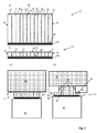
- Fig. 11 shows a section of a sixth inventive jointing tape 10 with self-adhesive layer 56 on the underside in perspective view with a main view of a longitudinal side 18.
- the joint sealing tape has two longitudinal sides 16, 18 and a in the installed state of the jointing tape 10 to a joint flank 20 adjacent top 22 and a in Installation state of the joint sealing strip 10 on the opposite joint edge 24 adjacent bottom 26. Between top 22 and bottom 26 and parallel or nearly parallel to the longitudinal sides 16, 18 extend six membrane layers 14 each in the longitudinal direction 28th
- the joint sealing strip 10 has on the upper side 22 a compressible projection 40 made of foam, which extends only in the longitudinal direction 28 and which is designed such that it from a compressed state into an optional recess 34 of a joint flank 20 can expand, while other portions 36 of the joint sealing strip, which are outside of at least one recess 40 in the recess 40 extending projection, not on the recess 34 having portion 38 of a joint flank 20 adjacent.
- the joint sealing strip 10 comprises seven foam elements 12, wherein the six membrane layers 14 are arranged between each two foam elements 12.
- the membrane layers 14 are distributed relatively uniformly over the width of the jointing sealing strip 10.
- the projection 40 is bonded as a separate part centrally with the top 22 of the joint sealing tape 10, but has no membrane layer itself.
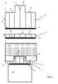
- Fig. 12 shows a section of a ninth inventive jointing tape 10 with self-adhesive layer 56 on the bottom 26 in a perspective view with a main view of a longitudinal side 18.
- the joint sealing tape has two longitudinal sides 16, 18 and in the installed state of the jointing tape 10 to the joint edge 20 adjacent upper side 22 and a in the installed state of the joint sealing strip 10 adjacent to the opposite joint edge 24 bottom 26. Between top 22 and bottom 26 and parallel or nearly parallel to the longitudinal sides 16, 18 extend six membrane layers 14 each in the longitudinal direction 28th
- the joint sealing strip 10 has on the upper side 22 extending only in the longitudinal direction 28 compressible projection 40 made of foam, which is designed such that it can expand from a compressed state into an optional recess 34 of a joint flank 20, while other portions 36 of Joint sealing tape, which lie outside the at least one projection 40 which expands into the recess 34, adjoin the region 38, not having the recess 34, of a joint flank 20.
- the joint sealing strip 10 comprises seven foam elements 12, wherein the six membrane layers 14 are each arranged between two foam elements 12.
- the membrane layers 14 are distributed relatively uniformly over the width of the jointing sealing strip 10.
- the projection 40 is arranged centrally and formed integrally with the top 22 of the joint sealing strip 10, wherein two of the membrane layers merge into the projection.
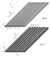
- Fig. 13 shows a side view of a roll form 42 in stock and pre-compressed second inventive jointing sealing strip 10 with an already unrolled, recovering section.
- the joint sealing strip 10 has two longitudinal sides 16, 18 and a in the installed state of the joint sealing strip 10 adjacent to the joint flank 20 top 22 and in the installed state of the joint sealing strip 10 adjacent to the opposite joint edge 24 bottom 26. Between the upper side 22 and the lower side 26 and parallel or nearly parallel to the longitudinal sides 16, 18, two membrane layers 14 extend in the longitudinal direction 28, respectively.
- the joint sealing strip 10 has three only in the longitudinal direction 28, parallel or nearly parallel to the longitudinal sides 16, 18 extending and introduced from the top 22 in the joint sealing tape 10 incisions 30 which are formed such that at least one between two incisions 30 existing section 32 of the joint sealing strip 10 from a compressed state in an optional recess 34 of a joint flank 20 can expand, while other portions 36 of the joint sealing strip 10, outside the at least lying in the recess 34 portion 32 are adjacent to the non-recess 34 having region 38 of a joint edge 20.
- the joint sealing strip 10 comprises three foam elements 12, wherein the two membrane layers 14 are each arranged between two foam sections 12.
- the membrane layers 14 are distributed relatively uniformly over the width of the joint sealing strip 10. In each case one membrane layer 14 is arranged in the region between two incisions 30.
- the panel 52 Before being rolled up, preferably on the side 26 opposite the at least one projection 40 or alternatively the incisions 30, the panel 52 is coated over its entire surface with a self-adhesive layer 56, which is preferably covered with a releasable silicone paper.
- Fig. 21 shows a schematic representation of a Altromesantechnik using a joint sealing tape according to the invention in three steps a), b) and c).
- Fig. 22 shows a schematic representation of another Alttensan ist with so-called clinker stop using a jointing tape according to the invention.
Landscapes
- Engineering & Computer Science (AREA)
- Architecture (AREA)
- Civil Engineering (AREA)
- Structural Engineering (AREA)
- Physics & Mathematics (AREA)
- Electromagnetism (AREA)
- Gasket Seals (AREA)
- Building Environments (AREA)
Abstract
Die Erfindung betrifft ein Fugendichtungsband.The invention relates to a joint sealing strip.
Description
Die vorliegende Erfindung betrifft ein komprimierbares Fugendichtungsband nach dem Oberbegriff des Anspruchs 1 sowie Verfahren zur Herstellung desselben.The present invention relates to a compressible jointing tape according to the preamble of claim 1 and to a method for producing the same.
Komprimierbare Fugendichtungsbänder zum Abdichten gegen Luftzug und Schlagregen sind beispielsweise aus der
Ein bekanntes Fugendichtungsband umfassend Schaumstoffelemente weist zwei Längsseiten sowie eine im Einbauzustand des Fugendichtungsbandes an die eine Fugenflanke, insbesondere eines Mauerwerks, angrenzende Oberseite und eine im Einbauzustand des Fugendichtungsbandes an die gegenüberliegende Fugenflanke, insbesondere des Bauteils, angrenzende Unterseite auf, wobei eine oder vorzugsweise mehrere Membranschichten jeweils in Längsrichtung zwischen Oberseite und Unterseite parallel bzw. nahezu parallel zu den Längsseiten zwischen zwei Schaumstoffelementen verlaufen.A known joint sealing strip comprising foam elements has two longitudinal sides and a in the installed state of the joint sealing strip on the joint edge, in particular masonry, adjacent top and in the installed state of the joint sealing strip on the opposite joint edge, in particular of the component, adjacent underside, wherein one or preferably a plurality of membrane layers each extending in the longitudinal direction between the top and bottom parallel or nearly parallel to the longitudinal sides between two foam elements.
Bekanntermaßen wird die Unterseite eines solchen Fugendichtungsbandes an dem abzudichtenden Bauteil, beispielsweise einem Fenster- und Türrahmen, angeklebt. Nach dem Einbau des Bauteils, beispielsweise in eine Gebäudewandöffnung, expandiert das zuvor komprimierte Fugendichtungsband, stellt sich also elastisch zurück, so dass die Oberseite des Fugendichtungsbandes am Mauerwerk der Gebäudewandöffnung angrenzt bzw. anliegt, und so das Bauteil am Mauerwerk der Gebäudewandöffnung abdichtet.As is known, the underside of such a joint sealing strip is glued to the component to be sealed, for example a window and door frame. After installation of the component, for example, in a building wall opening, the previously compressed joint sealing tape expands, so is elastic back, so that the top of the joint sealing tape adjacent to the masonry of the building wall opening or rests, and so seals the component on the masonry of the building wall opening.
Bei einem im Zusammenhang mit einer Altbausanierung vorgesehenen Fensteraustausch hinterlässt der ausgebaute alte Fensterrahmen eine umlaufende Aussparung im Mauerwerk der Gebäudewandöffnung. Beim anschließenden Einbau eines neuen Fensterrahmens in die Gebäudewandöffnung stellen bekannte Fugendichtungsbänder vielfach keine ausreichende Abdichtung im Bereich der Aussparung sicher.In the case of a window replacement provided in connection with an old building renovation, the removed old window frame leaves a circumferential recess in the masonry of the building wall opening. During the subsequent installation of a new window frame in the building wall opening known jointing tapes often do not ensure sufficient sealing in the recess.
Ausgehend von diesem Stand der Technik liegt der Erfindung die Aufgabe zugrunde, solche Fugendichtungsbänder derart weiterzuentwickeln, dass sie auch in dem genannten Fall der Altbausanierung die an sie gestellten Anforderungen hinsichtlich der Schlagregendichtheit, der Dampfdiffusionsoffenheit, der Wärmedämmung und der Luftdichtheit erfüllen. Zudem liegt der Erfindung die Aufgabe zugrunde, solche Fugendichtungsbänder derart weiterzuentwickeln, dass diese schnell und kostengünstig hergestellt werden können.Based on this prior art, the present invention seeks to further develop such jointing tapes such that they meet the requirements placed on them in terms of watertightness, the open to vapor diffusion, thermal insulation and airtightness in the said case of old buildings. In addition, the invention has the object, such jointing tapes further develop such that they can be made quickly and inexpensively.
Diese Aufgabe wird bei einem Fugendichtungsband nach dem Oberbegriff des Anspruchs 1 durch die kennzeichnenden Merkmale des Anspruchs 1 oder 6 sowie durch Verfahren zur Herstellung desselben gemäß der Ansprüche 11, 13 oder 15 gelöst. Weiterbildungen und vorteilhafte Ausgestaltungen der Erfindung ergeben sich aus den jeweiligen Unteransprüchen sowie der nachfolgenden Beschreibung.This object is achieved in a jointing tape according to the preamble of claim 1 by the characterizing features of claim 1 or 6 and by a method for producing the same according to the claims 11, 13 or 15. Further developments and advantageous embodiments of the invention will become apparent from the respective dependent claims and the following description.
Ein komprimierbares Fugendichtungsband mit Schaumstoffelementen, welches zwei Längsseiten sowie eine im Einbauzustand des Fugendichtungsbandes an die eine Fugenflanke angrenzende Oberseite und eine im Einbauzustand des Fugendichtungsbandes an die gegenüberliegende Fugenflanke angrenzende Unterseite aufweist, wobei eine oder vorzugsweise mehrere Membranschichten jeweils in Längsrichtung zwischen Oberseite und Unterseite sowie parallel bzw. nahezu parallel zu den Längsseiten zwischen zwei Schaumstoffelementen verlaufen, zeichnet sich erfindungsgemäß dadurch aus, dass das Fugendichtungsband wenigstens einen nur in Längsrichtung, parallel bzw. nahezu parallel zu den Längsseiten verlaufende und von der Oberseite in ein Schaumstoffelement des Fugendichtungsbandes eingebrachten Einschnitt aufweist, der derart ausgebildet ist, dass wenigstens ein Abschnitt des Fugendichtungsbandes aus einem komprimierten Zustand in eine gegebenenfalls vorhandene Aussparung der einen Fugenflanke expandieren kann, während wenigstens ein anderer Abschnitt des Fugendichtungsbandes, der außerhalb des wenigstens einen in die Aussparung expandierenden Abschnitts liegen, an den nicht die Aussparung aufweisenden Bereich der einen Fugenflanke angrenzen.A compressible joint sealing strip with foam elements, which has two longitudinal sides and one in the installed state of the joint sealing strip adjacent to the joint edge top and one in the installed state of the joint sealing strip adjacent to the opposite joint edge bottom, wherein one or preferably more membrane layers in the longitudinal direction between the top and bottom and parallel or run almost parallel to the longitudinal sides between two foam elements, according to the invention is characterized in that the joint sealing strip at least one extending only in the longitudinal direction, parallel or nearly parallel to the longitudinal sides and from the top into a Foam element of the joint sealing strip introduced incision, which is designed such that at least a portion of the joint sealing strip can expand from a compressed state into an optional recess of a joint edge, while at least another portion of the joint sealing strip, outside of at least one expanding into the recess Section lie on the not having the recess area of a joint edge.
Zwar ist aus der
Es kann von Vorteil sein, wenn das Fugendichtungsband wenigstens zwei nur in Längsrichtung, parallel bzw. nahezu parallel zu den Längsseiten verlaufende und von der Oberseite in ein oder mehr als ein Schaumstoffelement des Fugendichtungsbandes eingebrachte Einschnitte aufweist, die derart ausgebildet sind, dass wenigstens ein zwischen zwei Einschnitten vorhandener Abschnitt des Fugendichtungsbandes aus einem komprimierten Zustand in eine gegebenenfalls vorhandene Aussparung der einen Fugenflanke expandieren kann, während andere Abschnitte des Fugendichtungsbandes, die außerhalb des wenigstens einen in die Aussparung expandierenden Abschnitts liegen, an den nicht die Aussparung aufweisenden Bereich der einen Fugenflanke angrenzen.It may be advantageous if the joint sealing strip has at least two incisions extending only in the longitudinal direction, parallel or nearly parallel to the longitudinal sides and introduced from the top into one or more than one foam element of the joint sealing strip, which are formed such that at least one between two incisions existing portion of the joint sealing strip from a compressed state in an optional recess of a joint flank can expand, while other portions of the joint sealing strip, which lie outside the at least one recess in the recess portion adjacent to the not having the recess region of a joint flank ,
Es kann von Vorteil sein, wenn ein oder mehr als ein Einschnitt im nicht komprimierten Fugendichtungsband eine Länge aufweist, die wenigstens ½, vorzugsweise ¾ der Höhe des nicht komprimierten Fugendichtungsbandes entspricht.It may be advantageous if one or more than one incision in the uncompressed joint sealing strip has a length which corresponds at least to ½, preferably ¾, of the height of the uncompressed joint sealing strip.
Es kann von Vorteil sein, wenn zumindest in einem Abschnitt zwischen zwei Einschnitten, vorzugsweise in dem Abschnitt, der in die gegebenenfalls vorhandene Aussparung expandieren kann, keine Membranschicht angeordnet ist.It may be advantageous if no membrane layer is arranged at least in a section between two incisions, preferably in the section which can expand into the optionally existing recess.
Es kann zweckmäßig sein, wenn zumindest in einem Abschnitt zwischen zwei Einschnitten, welcher in die gegebenenfalls vorhandene Aussparung expandieren kann, wenigstens eine Membranschicht angeordnet und vorzugsweise derart ausgebildet ist, dass diese auch nach vollständiger Expansion des Abschnitts intakt ist.It may be expedient if, at least in one section between two incisions, which can expand into the optionally existing recess, at least one membrane layer is arranged and preferably designed such that it is intact even after complete expansion of the section.
Ein alternatives komprimierbares Fugendichtungsband mit Schaumstoffelementen, welches zwei Längsseiten sowie eine im Einbauzustand des Fugendichtungsbandes an die eine Fugenflanke angrenzende Oberseite und eine im Einbauzustand des Fugendichtungsbandes an die gegenüberliegende Fugenflanke angrenzende Unterseite aufweist, wobei eine oder vorzugsweise mehrere Membranschichten jeweils in Längsrichtung zwischen Oberseite und Unterseite sowie parallel bzw. nahezu parallel zu den Längsseiten zwischen zwei Schaumstoffelementen verlaufen, zeichnet sich erfindungsgemäß dadurch aus, dass das Fugendichtungsband auf der Oberseite wenigstens einen nur in Längsrichtung verlaufenden komprimierbaren Vorsprung aus Schaumstoff aufweist, der derart ausgebildet ist, dass dieser aus einem komprimierten Zustand in eine gegebenenfalls vorhandene Aussparung der einen Fugenflanke expandieren kann, während wenigstens ein anderer Abschnitt des Fugendichtungsbandes, der außerhalb des wenigstens einen in die Aussparung expandierenden Vorsprungs liegt, an den nicht die Aussparung aufweisenden Bereich der einen Fugenflanke angrenzt.An alternative compressible joint sealing strip with foam elements, which has two longitudinal sides and one in the installed state of the joint sealing strip adjacent to the joint edge top and one in the installed state of the joint sealing strip to the opposite joint edge bottom, wherein one or preferably more membrane layers in each case in the longitudinal direction between the top and bottom and run parallel or nearly parallel to the longitudinal sides between two foam elements, according to the invention is characterized in that the joint sealing tape on the top at least one extending only in the longitudinal direction compressible projection made of foam, which is designed such that this from a compressed state into a optionally present recess of a joint flank can expand, while at least one other portion of the joint sealing strip, outside the at least one in the recess expanding projection is adjacent to the not having the recess portion of a joint flank.
Es kann Vorteil sein, wenn wenigstens ein Vorsprung als separates Teil mit der Oberseite der Fugendichtungsbandes verbunden, vorzugsweise verklebt, ist.It may be advantageous if at least one projection is connected as a separate part to the top of the joint sealing strip, preferably glued.
Es kann vorteilhaft sein, wenn wenigstens ein Vorsprung einteilig mit der Oberseite des Fugendichtungsbandes ausgebildet ist.It may be advantageous if at least one projection is formed integrally with the top of the jointing sealing strip.
Es kann von Vorteil sein, wenn wenigstens ein Vorsprung wenigstens eine in Längsrichtung parallel bzw. nahezu parallel zu den Längsseiten verlaufende Membranschicht aufweist, wobei diese vorzugsweise in einem Stück das Schaumstoffelement und den Vorsprung durchläuft.It can be advantageous if at least one projection has at least one membrane layer running parallel or substantially parallel to the longitudinal sides in the longitudinal direction, wherein the latter preferably passes in one piece through the foam element and the projection.
Es kann vorteilhaft sein, wenn der auf der Oberseite des Fugendichtungsbandes vorgesehene Vorsprung mittig oder außermittig zwischen den Längsseiten, angeordnet ist, wobei ein außermittig angeordneter Vorsprung vorzugsweise mit einer der Längsseiten abschließt.It can be advantageous if the projection provided on the upper side of the joint sealing strip is arranged centrally or eccentrically between the longitudinal sides, wherein an off-centered projection preferably terminates with one of the longitudinal sides.
Es kann vorteilhaft sein, wenn wenigstens eine Membranschicht eine diffusionsdichte oder vorzugsweise eine diffusionsoffene Schicht, insbesondere in Form einer Folie, ist.It can be advantageous if at least one membrane layer is a diffusion-tight or preferably a vapor-permeable layer, in particular in the form of a film.
Es kann aber auch vorteilhaft sein, wenn wenigstens eine Membranschicht feuchtevariabel oder feuchteadaptiv ist.However, it can also be advantageous if at least one membrane layer is moisture-variable or moisture-adaptive.
Im Zusammenspiel mit dem in eine Aussparung der einen Fugenflanke expandierenden Abschnitts bzw. Vorsprungs wird insbesondere für die Altbausanierung ein Fugendichtungsband bereitgestellt, mit dem eine sichere Abdichtung von Fugen zwischen zusammengefügten Bauelementen im Hausbau, insbesondere zwischen Wandöffnungen einer Außenwand und Fenster- oder Türrahmen, erreicht wird, wobei vorteilhaft keine zusätzlichen Fugenbänder oder Hinterfüllmaterialien erforderlich sind. Da die Membranschichten feuchtevariabel bzw. feuchteadaptiv sind, ist vorteilhaft die Gefahr einer Verwechslung zwischen derjenigen Seite des Fugendichtungsbandes, welche im Einbauzustand nach innen weist, und derjenigen Seite des Fugendichtungsbandes, welche nach außen weist, ausgeschlossen. Vorteilhaft kann in einem Arbeitsgang eine äußere, mittlere und innere Abdichtung der Fuge zwischen zwei zusammengefügten Bauelementen erreicht werden. Durch die wenigstens eine feuchtevariable bzw. feuchteadaptive Membranschicht stellt sich die gewünschte Dichtheit des Fugendichtbandes abhängig von der Feuchtigkeit von selbst ein. Das Fugendichtungsband ist somit quasi ein intelligentes Fugendichtungsband und beim Einbau in die Fuge besteht keine Gefahr der Verwechslung von Innen- und Außenseite des Fugendichtungsbandes.In conjunction with the in a recess of a joint flank expanding portion or projection, a joint sealing tape is provided in particular for the renovation of old buildings, with a secure sealing of joints between assembled components in house construction, especially between wall openings of an outer wall and window or door frame is achieved , wherein advantageously no additional joint tapes or backfill materials are required. Since the membrane layers are moisture-variable or moisture-adaptive, advantageously the risk of confusion between that side of the joint sealing strip, which in the installed state facing inwards, and that side of the joint sealing strip facing outward, excluded. Advantageously, in one operation, an outer, middle and inner sealing of the joint between two assembled components can be achieved. Due to the at least one moisture-variable or moisture-adaptive membrane layer, the desired tightness of the joint sealing tape sets itself depending on the moisture. The joint sealing tape is thus virtually an intelligent joint sealing tape and when installed in the joint, there is no risk of confusion between the inside and outside of the joint sealing tape.
Eine Weiterbildung der Erfindung sieht vor, dass die Zusammensetzung der Membranschicht oder Membranschichten und/oder dass die Anordnung der Membranschicht oder Membranschichten und/oder dass die Anzahl der Membranschichten derart gewählt sind, dass das Fugendichtungsband in dem Bereich, der an eine Atmosphäre mit hoher Feuchte angrenzt, weniger dicht gegenüber Wasserdampf ist, als in dem Bereich, der an eine Atmosphäre mit niedrigerer Feuchte angrenzt.A development of the invention provides that the composition of the membrane layer or membrane layers and / or that the arrangement of the membrane layer or membrane layers and / or that the number of membrane layers are selected such that the joint sealing strip in the area, which in a high-humidity atmosphere is less dense than water vapor, than in the area adjacent to a lower humidity atmosphere.
Als feuchtevariable Membranschicht kann vorteilhaft eine modifizierte Polyamid-Folie eingesetzt werden. Solche Folien zeichnen sich dadurch aus, dass deren Dampfdurchlässigkeit im feuchten Zustand deutlich höher ist als im trockenen Zustand. Die Folien haben also einen variablen sd-Wert. Unter einem sd-Wert wird der Wasserdampf-Diffusionswiderstand eines Materials, auch als "diffusionsäquivalente Luftschichtdicke" bezeichnet, verstanden. Der sd-Wert mit der Einheit "m" berechnet sich aus der Schichtdicke des Materials multipliziert mit der Wasserdampfdiffusionswiderstandszahl des Materials, dem so genannten µ-Wert, wie in DIN EN ISO 12572:2001 definiert. Geeignete Membranschichten sind beispielsweise in der
Weitere geeignete Membranschichten sind beispielsweise in der
Es kann von Vorteil sein, wenn das Fugendichtungsband zwei Längsseiten sowie eine im Einbauzustand des Fugendichtungsbandes an die eine Fugenflanke angrenzende Ober- und eine im Einbauzustand des Fugendichtungsbandes an die gegenüberliegende Fugenflanke angrenzende Unterseite aufweist, wobei die Membranschicht oder Membranschichten jeweils in Längsrichtung zwischen Ober- und Unterseite sowie vorzugsweise parallel bzw. nahezu parallel zu den Längsseiten verlaufen. Die Breite des Fugendichtungsbandes ist somit der Abstand zwischen zwei Längsseiten.It may be advantageous if the joint sealing strip has two longitudinal sides and one in the installed state of the joint sealing strip adjacent to the joint edge upper and one in the installed state of the joint sealing strip adjacent to the opposite joint edge bottom, wherein the membrane layer or membrane layers in the longitudinal direction between upper and Bottom and preferably parallel or almost parallel to the longitudinal sides. The width of the joint sealing strip is thus the distance between two longitudinal sides.
Eine Weiterbildung der Erfindung sieht vor, dass die Zusammensetzung der Membranschicht oder Membranschichten und/oder dass die Anordnung der Membranschicht oder Membranschichten und/oder dass die Anzahl der Membranschichten derart gewählt sind, dass das Fugendichtungsband in dem Bereich, der an eine Atmosphäre mit hoher Feuchte angrenzt, dichter gegenüber Wasserdampf ist, als in dem Bereich, der an eine Atmosphäre mit niedrigerer Feuchte angrenzt.A development of the invention provides that the composition of the membrane layer or membrane layers and / or that the arrangement of the membrane layer or membrane layers and / or that the number of membrane layers are selected such that the joint sealing strip in the area, which in a high-humidity atmosphere adjacent to it is closer to water vapor than in the area adjacent to a lower humidity atmosphere.
Ein erfindungsgemäßes Fugendichtungsband ist universell für die Abdichtung einer Fuge zwischen zwei zusammengefügten Bauelementen, beispielsweise zwischen einem Baukörper, insbesondere einem Mauerwerk, und einem Rahmen oder dergleichen, insbesondere einem Fenster- oder Türrahmen, einsetzbar. Ein solches, in eine entsprechende Fuge eingebautes Fugendichtungsband hat den Vorteil, dass dieses jeweils auf der Seite bzw. dem Bereich, der einer höheren Diffusionsbelastung ausgesetzt ist, eine höhere Sperrwirkung hat. Das hat wiederum hat den Vorteil, dass beim Einbau eines erfindungsgemäßen Fugendichtungsbandes nicht darauf geachtet werden braucht, welche der beiden Längsseite des Fugendichtungsbandes zur Innenraumseite bzw. nach innen und welche zur Außenraumseite bzw. nach außen angeordnet ist. Der Einbau bzw. die Verlegung eines erfindungsgemäßen Fugendichtungsbandes ist somit unabhängig von der Laufrichtung des Bandes.An inventive joint sealing strip is universally used for the sealing of a joint between two assembled components, for example between a building, in particular a masonry, and a frame or the like, in particular a window or door frame. Such, in a corresponding joint built-in joint sealing tape has the advantage that this each on the side or the area which is exposed to a higher diffusion load, has a higher barrier effect. This in turn has the advantage that when installing a jointing tape according to the invention does not need to be taken care of which of the two longitudinal side of the joint sealing strip to the interior side or inwards and which is arranged to the outside space side or to the outside. The installation or laying of a joint sealing tape according to the invention is thus independent of the direction of the tape.
Die Membranschicht oder Membranschichten können wie Sperrschichten axial im Fugendichtungsband angeordnet sein, so dass diese nach dem Einbau des Fugendichtungsbandes im Wesentlichen quer zur Diffusionsrichtung angeordnet sind.The membrane layer or membrane layers, like barrier layers, can be arranged axially in the joint-sealing strip, so that these are arranged essentially transversely to the direction of diffusion after installation of the joint-sealing strip.
Ein erfindungsgemäßes Fugendichtungsband ist feuchtigkeitsvariabel, vorzugsweise derart, dass immer die Seite, die der feuchteren Atmosphäre ausgesetzt ist, diffusionsdichter ist. Dadurch wird erfindungsgemäß immer Feuchtigkeit aus der Fuge heraustransportiert und ein Hineindiffundieren von Feuchtigkeit in die Fuge verhindert.A jointing tape according to the invention is moisture-variable, preferably in such a way that always the side which is exposed to the more humid atmosphere is diffusion-tight. As a result, according to the invention, moisture is always transported out of the joint and prevents moisture from diffusing into the joint.
Ein erfindungsgemäßes Fugendichtungsband funktioniert bei der in der nach RAL Gütegemeinschaft Fenster und Haustüren e. V. (RAL-Leitfaden zur Planung und Ausführung der Montage von Fenstern und Haustüren März 2014) geforderten typischen Winter-Situation, bei welcher die Abdichtung zum Innenraum bzw. nach innen dichter sein soll als die Abdichtung zum Außenraum bzw. nach außen, da im Winter Innenräume eine größere Luftfeuchtigkeit als Außenräume bzw. die Außenatmosphäre aufweisen. Ein erfindungsgemäßes Fugendichtungsband funktioniert aber auch in der typischen Sommer-Situation, in der sich die Diffusion umkehrt und die Außenumgebung eine höhere Luftfeuchtigkeit aufweist.A jointing tape according to the invention works in the RAL quality community windows and doors e. V. (RAL Guide to Planning and Execution of the Installation of Windows and Front Doors March 2014) required typical winter situation in which the seal to the interior or to the inside should be denser than the seal to the outside or to the outside, as in the Winter indoor spaces have a higher humidity than outdoor spaces or the outside atmosphere. An inventive jointing tape works but also in the typical summer situation, where the diffusion reverses and the outside environment has a higher humidity.
Dadurch wird insgesamt eine ganzjährige Austrocknung der Fuge erreicht. So wird die RAL-Forderung des Schutzes der so genannten Anschlussfuge zwischen Baukörper und beispielsweise Fensterahmen vor außen- und raumseitigen Belastungen sichergestellt.As a result, a total of year-round dehydration of the joint is achieved. Thus, the RAL requirement of the protection of the so-called connecting joint between the building and, for example, window frames is ensured against outside and room-side loads.
Es kann zweckmäßig sein, wenn wenigstens eine Membranschicht so ausgebildet ist, dass diese bei einer mittleren relativen Feuchte der sie umgebenden Atmosphäre von bis zu 50 % einen Wasserdampfdiffusionswiderstand (µ-Wert) von kleiner 15 und bei einer mittleren relativen Feuchte der sie umgebenden Atmosphäre von mehr als 70 % einen Wasserdampfdiffusionswiderstand (µ-Wert) von größer 30 aufweist.It may be expedient if at least one membrane layer is formed so that it has a mean relative humidity of the surrounding atmosphere of up to 50%, a water vapor diffusion resistance (μ value) of less than 15 and at an average relative humidity of the surrounding atmosphere of more than 70% has a water vapor diffusion resistance (μ value) greater than 30.
Für bestimmte Einsatzwecke kann es auch vorteilhaft sein, wenn ein Fugendichtungsband mehrere unterschiedliche Dichtbereiche aufweist, indem die Zusammensetzung der Membranschicht oder Membranschichten, die Anordnung der Membranschicht oder Membranschichten und/oder die Anzahl der Membranschichten in einem Dichtbereich derart gewählt sind, dass das Fugendichtungsband in dem Bereich, der an eine Atmosphäre mit hoher Feuchte angrenzt, dichter gegenüber Wasserdampf ist, als in dem Bereich, der an eine Atmosphäre mit niedrigerer Feuchte angrenzt, und in einem anderen Dichtbereich derart gewählt sind, dass das Fugendichtungsband in dem Bereich, der an eine Atmosphäre mit hoher Feuchte angrenzt, weniger dicht gegenüber Wasserdampf ist, als in dem Bereich, der an eine Atmosphäre mit niedrigerer Feuchte angrenzt.For certain purposes, it may also be advantageous if a joint sealing tape has several different sealing areas by the composition of the membrane layer or membrane layers, the arrangement of the membrane layer or membrane layers and / or the number of membrane layers are selected in a sealing region such that the joint sealing tape in the Area adjacent to a high humidity atmosphere is closer to water vapor than in the area adjacent to a lower humidity atmosphere and in another sealing area such that the jointing tape in the area adjacent to an atmosphere is adjacent to high humidity, less dense to water vapor than in the area adjacent to a lower humidity atmosphere.
Es kann von Vorteil sein, wenn der Schaumstoff ein überwiegend offenzelliger Rohschaum ist.It may be advantageous if the foam is a predominantly open-cell raw foam.
Es kann aber auch von Vorteil sein, wenn der Schaumstoff ein überwiegend geschlossenzelliger Rohschaum ist, wie er beispielsweise in der
Es kann zweckmäßig sein, wenn der Schaumstoff ein imprägnierter, vorzugsweise ein homogen imprägnierter Rohschaum ist. Ein solch imprägnierter Schaumstoff eignet sich besonders gut für die einfache und universelle Fugenabdichtung, wobei die Imprägnierung insbesondere für eine verzögerte Rückstellung des komprimierbaren, vorzugsweise vorkomprimierten Fugendichtungsbandes sorgt. Es kann ein Vorteil sein, wenn das Imprägnat flammhemmend ausgerüstet ist. Insbesondere kann es von Vorteil sein, wenn das Imprägnat derart flammhemmend ausgerüstet ist, dass das Produkt in seinem angegebenen Anwendungsbereich wenigstens einer der gängigen Brandnormen für den Baubereich entspricht, beispielsweise DIN 4102-B1 und/oder DIN 4102-B2 und/oder DIN 4102-≥F30 und/oder EN13501 Klasse E bis B und/oder EN 13501>R30 bzw. >EI30.It may be expedient if the foam is an impregnated, preferably a homogeneously impregnated raw foam. Such an impregnated foam is particularly well suited for simple and universal joint sealing, wherein the impregnation provides in particular for a delayed recovery of the compressible, preferably precompressed joint sealing strip. It can be an advantage if the impregnate is flame-retardant. In particular, it may be advantageous if the impregnate is equipped in such a flame-retardant manner that the product in its stated field of application corresponds to at least one of the common fire standards for the construction sector, for example DIN 4102-B1 and / or DIN 4102-B2 and / or DIN 4102- ≥F30 and / or EN13501 Class E to B and / or EN 13501> R30 or> EI30.
Eine vorteilhafte Ausgestaltung der Erfindung sieht vor, dass der Schaumstoff bzw. jedes Schaumstoffelement ein vorzugsweise derart mit Acrylaten imprägnierter Rohschaum ist, dass der Wasserdampfdiffusionswiderstand des im Einbauzustand vorliegenden Schaumstoffs bzw. jedes Schaumstoffelements kleiner ist als der Wasserdampfdiffusionswiderstand wenigstens einer, vorzugsweise jeder Membranschicht.An advantageous embodiment of the invention provides that the foam or each foam element is preferably impregnated with acrylates raw foam, that the water vapor diffusion resistance of the present in the installed state foam or each foam element is smaller than the water vapor diffusion resistance of at least one, preferably each membrane layer.
Eine Weiterbildung der Erfindung sieht vor, dass wenigstens eine Membranschicht aus Klebstoff, vorzugsweise aus einem Acrylathaftklebstoff oder einem Gemisch aus Acrylathaftklebstoff und Polyurethanklebstoff, gebildet ist.A further development of the invention provides that at least one membrane layer is formed from adhesive, preferably from an acrylate pressure-sensitive adhesive or a mixture of acrylate pressure-sensitive adhesive and polyurethane adhesive.
Es kann zweckmäßig sein, wenn wenigstens eine Membranschicht aus wenigstens einem wasserfesten modifizierten Acrylat gebildet ist, wodurch hochleistungsfähige, feuchtevariable Membranschichten bereitgestellt werden, die je nach Zusammensetzung bei hoher Luftfeuchte diffusionsdichter sind als bei niedrigerer Luftfeuchtigkeit oder umgekehrt.It may be expedient if at least one membrane layer is formed from at least one water-resistant modified acrylate, resulting in high-performance, moisture-variable membrane layers are provided, which are diffusion-tight depending on the composition at high humidity than at lower humidity or vice versa.
Es kann von Vorteil sein, wenn wenigstens eine Membranschicht aus einer modifizierten Polyamid-Folie gebildet ist, die vorzugsweise mit dem Schaumstoff bzw. Schaumstoffelement verklebt ist.It may be advantageous if at least one membrane layer is formed from a modified polyamide film, which is preferably glued to the foam or foam element.
Es kann auch vorteilhaft sein, wenn wenigstens eine Membranschicht aus einer Polyamid-Dispersion, vorzugsweise in Form eines Klebstoffs, gebildet ist.It may also be advantageous if at least one membrane layer is formed from a polyamide dispersion, preferably in the form of an adhesive.
Eine Weiterbildung der Erfindung sieht vor, dass das Auftragsgewicht eines Klebstoffs zur Bildung oder Mitbildung einer Membranschicht 60 bis 200 g/m2, vorzugsweise 100 bis 150 g/m2 beträgt. Für bestimmte Anwendungen kann es vorteilhaft sein, wenn das Auftragsgewicht 100 bis 119 g/m2 beträgt. Für gewisse Anwendungen kann es vorteilhaft sein, wenn das Auftragsgewicht 120 bis 130 g/m2 beträgt. Für manche Anwendungen kann es vorteilhaft sein, wenn das Auftragsgewicht 131 bis 150 g/m2 beträgt.A development of the invention provides that the application weight of an adhesive for forming or co-formation of a membrane layer is 60 to 200 g / m 2 , preferably 100 to 150 g / m 2 . For certain applications, it may be advantageous if the application weight is 100 to 119 g / m 2 . For certain applications, it may be advantageous if the application weight is 120 to 130 g / m 2 . For some applications, it may be advantageous if the application weight is 131 to 150 g / m 2 .
Eine vorteilhafte Ausgestaltung der Erfindung sieht vor, dass der Klebstoff zur Bildung der Membranschicht eine Klebkraft nach AFERA 4001 von > 20 N/25 mm aufweist.An advantageous embodiment of the invention provides that the adhesive for forming the membrane layer has an adhesive force according to AFERA 4001 of> 20 N / 25 mm.
Es kann zweckmäßig sein, wenn wenigstens eine Membranschicht einen größeren Wasserdampfdiffusionswiderstand aufweist als der Schaumstoff bzw. jedes Schaumstoffelement.It may be expedient if at least one membrane layer has a greater water vapor diffusion resistance than the foam or each foam element.
Eine Weiterbildung der Erfindung sieht vor, dass wenigstens zwei Membranschichten eine voneinander unterschiedliche Zusammensetzung haben.A development of the invention provides that at least two membrane layers have a mutually different composition.
Eine Weiterbildung sieht vor, dass die Membranschicht oder Membranschichten zur Erfüllung verbesserter Diffusionswerte dauerelastisch sind, so dass die Membranschichten auch nach Alterung im komprimierten Zustand und anschließender Dekomprimierung bzw. Rückstellung dauerhaft elastisch bleiben und im Einbauzustand der Fugendichtungsbandes in einer Fuge jederzeit dicht an den Fugenflanken anliegen.A further development provides that the membrane layer or membrane layers to fulfill improved diffusion values are permanently elastic, so that the membrane layers remain permanently elastic even after aging in the compressed state and subsequent decompression and recovery and in the installed state of the joint sealing strip in a gap at all times abut tightly against the joint edges ,
Es kann von Vorteil sein, wenn das Fugendichtungsband zusätzlich oder anstelle der innen liegenden Membranschichten wenigstens eine Membranschicht auf einer oder jeweils auf beiden Längsseiten aufweist.It may be advantageous if the joint sealing strip additionally or instead of the inner membrane layers has at least one membrane layer on one or on both longitudinal sides.
Eine Weiterbildung der Erfindung sieht vor, dass bei Verwendung von mehreren Membranschichten diese jeweils den gleichen und/oder einen unterschiedlichen Abstand zwischen 5 mm und 100 mm voneinander aufweisen können. Für gewisse Anwendungsfälle kann es vorteilhaft sein, wenn der Abstand zwischen 5 mm und 13 mm beträgt. Für bestimmte Anwendungsfälle kann es vorteilhaft sein, wenn der Abstand zwischen 14 mm und 20 mm beträgt. Für manche Anwendungsfälle kann es vorteilhaft sein, wenn der Abstand zwischen 21 mm und 30 mm beträgt. Für ganz andere Anwendungsfälle kann es von Vorteil sein, wenn der Abstand zwischen 31 mm und 100 mm beträgt.A development of the invention provides that, when using a plurality of membrane layers, these can each have the same and / or a different distance between 5 mm and 100 mm from one another. For certain applications, it may be advantageous if the distance between 5 mm and 13 mm. For certain applications, it may be advantageous if the distance is between 14 mm and 20 mm. For some applications, it may be advantageous if the distance is between 21 mm and 30 mm. For completely different applications, it may be advantageous if the distance between 31 mm and 100 mm.
Eine Weiterbildung der Erfindung sieht vor, dass sich der Abstand zwischen zwei Membranschichten vorteilhaft vom Abstand zwischen zwei anderen Membranschichten unterscheidet.A development of the invention provides that the distance between two membrane layers advantageously differs from the distance between two other membrane layers.
Es bestimmte Einsatzfälle kann es zweckmäßig sein, wenn die Membranschicht bzw. die Membranschichten gleichmäßig über die Breite des Fugendichtungsbandes verteilt bzw. angeordnet sind.It may be appropriate applications, if the membrane layer or the membrane layers are evenly distributed or arranged over the width of the joint sealing strip.
Für gewisse Einsatzfälle kann es aber auch zweckmäßig sein, wenn die Membranschicht bzw. die Membranschichten ungleichmäßig über die Breite des Fugendichtungsbandes verteilt bzw. angeordnet sind.For certain applications, however, it may also be expedient if the membrane layer or the membrane layers are distributed or arranged unevenly over the width of the joint sealing strip.
So kann es für einige Einsatzfälle vorteilhaft sein, wenn die Membranschicht bzw. Membranschichten in der Nähe einer oder beider Längsseiten des Fugendichtungsbandes angeordnet sind. Es kann aber für einige andere Einsatzfälle auch vorteilhaft sein, wenn die Membranschicht bzw. Membranschichten weiter entfernt von einer oder beiden Längsseiten des Fugendichtungsbandes angeordnet sind.Thus, it may be advantageous for some applications when the membrane layer or membrane layers are arranged in the vicinity of one or both longitudinal sides of the joint sealing strip. However, it may also be advantageous for some other applications if the membrane layer or membrane layers are arranged further away from one or both longitudinal sides of the joint sealing strip.
Für manche Einsatzfälle kann es vorteilhaft sein, wenn der Abstand der Membranschichten von einer Längsseite zur anderen Längsseite des Fugendichtungsbandes variiert, vorzugsweise abnimmt und/oder zunimmt.For some applications, it may be advantageous if the distance between the membrane layers varies from one longitudinal side to the other longitudinal side of the jointing sealing strip, preferably decreases and / or increases.
Eine Weiterbildung der Erfindung sieht vor, dass die durch wenigstens eine Membranschicht unterteilten in Längsrichtung verlaufenden Schaumstoffelemente derart unterschiedlich ausgebildet sind, dass das Fugendichtungsband in dem Bereich, der an eine Atmosphäre mit hoher Feuchte angrenzt, dichter gegenüber Wasserdampf ist, als in dem Bereich, der an eine Atmosphäre mit niedrigerer Feuchte angrenzt.A further development of the invention provides that the longitudinally extending foam elements divided by at least one membrane layer are configured differently such that the joint sealing strip in the area adjoining a high-humidity atmosphere is closer to water vapor than in the area that adjacent to a lower humidity atmosphere.
Eine Weiterbildung der Erfindung sieht vor, dass die durch wenigstens eine Membranschicht unterteilten in Längsrichtung verlaufenden Schaumstoffelemente derart unterschiedlich ausgebildet sind, dass das Fugendichtungsband in dem Bereich, der an eine Atmosphäre mit hoher Feuchte angrenzt, weniger dicht gegenüber Wasserdampf ist, als in dem Bereich, der an eine Atmosphäre mit niedrigerer Feuchte angrenzt.A further development of the invention provides that the longitudinally extending foam elements subdivided by at least one membrane layer are designed differently such that the joint-sealing strip in the area adjoining a high-humidity atmosphere is less dense with respect to water vapor than in the area, adjacent to a lower humidity atmosphere.
Für manche Einsatzzwecke kann es aber auch vorteilhaft sein, wenn mehrere Dichtbereiche innerhalb eines Fugendichtungsbandes vorgesehen sind, indem in einem Dichtbereich die durch wenigstens eine Membranschicht unterteilten in Längsrichtung verlaufenden Schaumstoffelemente derart unterschiedlich ausgebildet sind, dass das Fugendichtungsband in dem Bereich, der an eine Atmosphäre mit hoher Feuchte angrenzt, weniger dicht gegenüber Wasserdampf ist, als in dem Bereich, der an eine Atmosphäre mit niedrigerer Feuchte angrenzt, und in einem anderen Dichtbereich die durch wenigstens eine Membranschicht unterteilten in Längsrichtung verlaufenden Schaumstoffelemente derart unterschiedlich ausgebildet sind, dass das Fugendichtungsband in dem Bereich, der an eine Atmosphäre mit hoher Feuchte angrenzt, dichter gegenüber Wasserdampf ist, als in dem Bereich, der an eine Atmosphäre mit niedrigerer Feuchte angrenzt.For some applications, however, it may also be advantageous if a plurality of sealing areas are provided within a joint sealing strip by formed in a sealing region divided by at least one membrane layer extending in the longitudinal direction of foam elements are so different that the joint sealing tape in the area, which in an atmosphere with adjacent to high humidity, less dense to water vapor than in the area adjacent to a lower humidity atmosphere, and in another sealing area formed by at least one membrane layer divided longitudinally extending foam elements are designed differently such that the joint sealing tape in the area which is adjacent to a high humidity atmosphere, is more dense to water vapor than in the area adjacent to a lower humidity atmosphere.
Es kann vorteilhaft sein, wenn wenigstens zwei Schaumstoffelemente unterschiedliche Raumgewichte aufweisen.It may be advantageous if at least two foam elements have different spatial weights.
Es kann zweckmäßig sein, wenn der Schaumstoff bzw. jedes Schaumstoffelement ein PUR-Schaumstoff, vorzugsweise ein PUR-Weichschaumstoff ist. Dieser stellt sich nach einer Vorkomprimierung besonders gut innerhalb der Fuge zurück und sorgt für eine dauerhafte Abdichtung.It may be expedient if the foam or each foam element is a PUR foam, preferably a flexible polyurethane foam. This returns after a Vorkomprimierung particularly well within the joint and ensures a permanent seal.
Es kann vorteilhaft sein, wenn der Schaumstoff bzw. die Schaumstoffelemente mehrere Funktionsbereiche aufweist, vorzugsweise einen ersten nach außen schlagregendichten Bereich, einen zweiten wärmedämmenden sowie schallmindernden Bereich und einen dritten nach innen luftdichten Bereich. Die Membranschichten sorgen hierbei vorteilhaft für eine Abgrenzung der vorgenannten Funktionsebenen bzw. der so genannten Funktionsbereiche, wie von der RAL Gütegemeinschaft Fenster & Haustüren e. V. gefordert. Es kann eine Wärmedämmung erreicht werden, welche allen Anforderungen der Energiereinsparverordnung beim Fenstereinbau und der VOB für Tischlerarbeiten gemäß DIN 18355 erfüllt.It may be advantageous if the foam or the foam elements has a plurality of functional areas, preferably a first outwardly impact-proof area, a second heat-insulating and sound-reducing area and a third inwardly airtight area. In this case, the membrane layers advantageously provide for delimitation of the abovementioned functional levels or the so-called functional areas, such as those of the RAL Quality Assurance Association Fenster & Haustüren e. V. demanded. It can be achieved thermal insulation, which meets all the requirements of the Energy Saving Ordinance when installing windows and the VOB for carpentry according to DIN 18355.
Es kann zweckmäßig sein, wenn das Fugendichtungsband komprimierbar, vorzugsweise vorkomprimiert ist.It may be expedient if the joint sealing strip is compressible, preferably precompressed.
Vorteilhaft kann das Fugendichtungsband in Rollenform vorkomprimiert und verzögert rückstellfähig sein.Advantageously, the joint sealing tape can be pre-compressed in roll form and can be resiliently retarded.
Vorzugsweise beträgt die Dicke des Fugendichtungsbandes im nicht komprimierten Zustand zwischen 10 mm und 100 mm, vorzugsweise zwischen 18 mm bis 60 mm. Diese Angaben umfassen nicht die Dicke des Vorsprungs. Dessen Dicke wird in abhängig der Tiefe der Aussparung gewählt und beträgt üblicherweise zwischen 10 mm und 40 mm, vorzugsweise zwischen 15 mm und 25 mmm, besonders bevorzugt 20 mm.Preferably, the thickness of the joint sealing strip in the uncompressed state is between 10 mm and 100 mm, preferably between 18 mm and 60 mm. This information does not include the thickness of the projection. Its thickness is selected depending on the depth of the recess and is usually between 10 mm and 40 mm, preferably between 15 mm and 25 mm, particularly preferably 20 mm.
Eine Weiterbildung der Erfindung sieht vor, dass das Fugendichtungsband zur Abdichtung von Fugen zwischen zusammengefügten Bauelementen im Hausbau, insbesondere zwischen Wandöffnungen einer Außenwand und Fenster- oder Türrahmen, vorzugsweise ohne Zuhilfenahme zusätzlicher Fugenbändern oder Hinterfüllmaterialien, einsetzbar ist.A development of the invention provides that the joint sealing strip for sealing joints between assembled components in house construction, in particular between wall openings of an outer wall and window or door frame, preferably without the aid of additional joint tapes or backfill materials, can be used.
Die Erfindung betrifft außerdem ein Verfahren zur Herstellung eines Fugendichtungsbandes, das durch folgende Verfahrensschritte gekennzeichnet ist:
- a) Ausbilden von großflächigen Membranschichten durch lagenweises Laminieren und/oder Verkleben von Platten- oder Bahnware eines Schaumstoffs zu Laminatblöcken,
- b) Trennen der Laminatblöcke orthogonal zu den großflächigen Membranschichten aus Laminierungsmaterial und/ oder Klebstoff zu Tafeln mit Membranschichten und Schaumstoffelementen, so dass sich nach dem Trennen Membranschichten parallel zu einem Rand der Tafel und senkrecht durch die Tafel jeweils zwischen zwei Schaumstoffelementen erstrecken,
- c) Einbringen von im Wesentlichen parallel zu den Membranschichten verlaufenden Einschnitten in die Tafel
- d) Aufrollen einer Tafel zu einer Rolle, so dass die Membranschichten und die Einschnitte und die Schaumstoffelemente auf dem Umfang der Rolle in axialer Richtung aufgereiht sind, und
- e) Trennen der Rolle in Scheiben zu aufgerollten Fugendichtungsbändern mit wenigstens einer innerhalb des Fugendichtungsbandes zwischen zwei Schaumstoffelementen angeordneten Membranschicht sowie wenigstens einem innerhalb des Fugendichtungsbandes in einem Schaumstoffelement angeordneten Einschnitt.
- a) forming large-area membrane layers by layer-wise lamination and / or bonding of a plate or web of a foam to laminate blocks,
- b) separating the laminate blocks orthogonal to the large-area membrane layers of lamination material and / or adhesive to sheets having membrane layers and foam elements so that after separation membrane layers extend parallel to an edge of the sheet and perpendicularly through the sheet between each two foam elements,
- c) introduction of substantially parallel to the membrane layers extending incisions in the panel
- d) rolling a panel into a roll, so that the membrane layers and the incisions and the foam elements are lined up on the circumference of the roll in the axial direction, and
- e) separating the roll into slices to rolled joint sealing tapes with at least one arranged within the joint sealing tape between two foam elements membrane layer and at least one arranged within the joint sealing strip in a foam element incision.
Es kann vorteilhaft sein, wenn der Schaumstoff bzw. die Schaumstoffelemente nach dem Laminieren und/oder Verkleben und/oder vor oder nach dem Einbringen der Einschnitte getränkt bzw. imprägniert werden.It may be advantageous if the foam or the foam elements are impregnated or impregnated after lamination and / or gluing and / or before or after the introduction of the incisions.
Es kann von Vorteil sein, wenn die Tafel vor dem Aufrollen, vorzugsweise auf der den Einschnitten gegenüberliegenden Seite, vollflächig mit einer Selbstklebeschicht oder nicht vollflächig mit einer oder mehr als einer Selbstklebebahn beschichtet wird, welche vorzugsweise mit einem lösbaren Silikonpapier abgedeckt wird.It may be advantageous if, before rolling up, preferably on the side opposite the incisions, the panel is coated over its entire surface with a self-adhesive layer or not over its entire area with one or more self-adhesive sheets, which is preferably covered with a releasable silicone paper.
Die Erfindung betrifft außerdem ein Verfahren zur Herstellung eines Fugendichtungsbandes, das durch folgende Verfahrensschritte gekennzeichnet ist:
- a) Ausbilden von großflächigen Membranschichten durch lagenweises Laminieren und/oder Verkleben von Platten- oder Bahnware eines Schaumstoffs zu Laminatblöcken,
- b) Trennen der Laminatblöcke orthogonal zu den großflächigen Membranschichten aus Laminierungsmaterial und/ oder Klebstoff zu Tafeln mit Membranschichten und Schaumstoffelementen, so dass sich nach dem Trennen Membranschichten parallel zu einem Rand der Tafel und senkrecht durch die Tafel jeweils zwischen zwei Schaumstoffelementen erstrecken,
- c) Aufbringen und Verbinden, vorzugsweise Verkleben, von im Wesentlichen parallel zu den Membranschichten verlaufenden komprimierbaren Schaumstoffstreifen als Vorsprünge auf die Tafel
- d) Aufrollen einer Tafel zu einer Rolle, so dass die Membranschichten und die Vorsprünge und die Schaumstoffelemente auf dem Umfang der Rolle in axialer Richtung aufgereiht sind, und
- e) Trennen der Rolle zwischen einzelnen Vorsprüngen in Scheiben zu aufgerollten Fugendichtungsbändern mit wenigstens einer innerhalb des Fugendichtungsbandes zwischen zwei Schaumstoffelementen angeordneten Membranschicht sowie mindestens einem Vorsprung.
- a) forming large-area membrane layers by layer-wise lamination and / or bonding of a plate or web of a foam to laminate blocks,
- b) separating the laminate blocks orthogonal to the large-area membrane layers of lamination material and / or adhesive to sheets having membrane layers and foam elements so that after separation membrane layers extend parallel to an edge of the sheet and perpendicularly through the sheet between each two foam elements,
- c) application and bonding, preferably bonding, of compressible foam strips extending substantially parallel to the membrane layers as projections on the board
- d) rolling a panel into a roll, so that the membrane layers and the projections and the foam elements are lined up on the circumference of the roll in the axial direction, and
- e) separating the roll between individual projections into slices to rolled joint sealing tapes having at least one membrane layer arranged within the joint sealing strip between two foam elements and at least one projection.
Es kann vorteilhaft sein, wenn der Schaumstoff bzw. die Schaumstoffelemente nach dem Laminieren und/oder Verkleben und/oder nach oder vorzugsweise vor dem Aufbringen der Vorsprünge getränkt bzw. imprägniert wird. Werden Schaumstoff bzw. die Schaumstoffelemente nach dem Aufbringen der Vorsprünge getränkt bzw. imprägniert, erhalten die Vorsprünge ebenfalls eine Imprägnierungen. Werden Schaumstoff bzw. die Schaumstoffelemente vor dem Aufbringen der Vorsprünge getränkt bzw. imprägniert, so kann es vorteilhaft sein, wenn die Vorsprünge für sich entweder nicht getränkt bzw. imprägniert oder vorab getränkt bzw. imprägniert werden.It may be advantageous if the foam or the foam elements are impregnated or impregnated after lamination and / or gluing and / or after or preferably before the application of the protrusions. If foam or the foam elements are impregnated or impregnated after the application of the projections, the projections likewise receive impregnations. If foam or the foam elements are impregnated or impregnated prior to the application of the projections, then it may be advantageous if the projections are either not soaked or impregnated or pre-soaked or impregnated.
Es kann zweckmäßig sein, wenn die Tafel vor dem Aufrollen, vorzugsweise auf der dem wenigstens einen Vorsprung gegenüberliegenden Seite, vollflächig mit einer Selbstklebeschicht oder nicht vollflächig mit einer oder mehr als einer Selbstklebebahn beschichtet wird, welche vorzugsweise mit einem lösbaren Silikonpapier abgedeckt wird.It may be expedient if the panel before rolling, preferably on the opposite side of the at least one projection, is coated over the entire surface with a self-adhesive layer or not over the entire surface with one or more than one self-adhesive sheet, which is preferably covered with a releasable silicone paper.
Die Erfindung betrifft zudem ein Verfahren zur Herstellung eines Fugendichtungsbandes, das durch folgende Verfahrensschritte gekennzeichnet ist:
- a) Ausbilden von großflächigen Membranschichten durch lagenweises Laminieren und/oder Verkleben von Platten- oder Bahnware eines Schaumstoffs zu Laminatblöcken,
- b) Trennen der Laminatblöcke orthogonal zu den großflächigen Membranschichten aus Laminierungsmaterial und/ oder Klebstoff zu Tafeln mit Membranschichten und Schaumstoffelementen, so dass sich nach dem Trennen Membranschichten parallel zu einem Rand der Tafel und senkrecht durch die Tafel jeweils zwischen zwei Schaumstoffelementen erstrecken,
- c) Trennen der einzelnen Tafel in jeweils zwei Hälften, wobei jede Hälfte auf der Trennseite in Längsrichtung verlaufende Vorsprünge aufweist,
- d) Aufrollen jeder Tafelhälfte zu einer Rolle, so dass die Membranschichten und die Vorsprünge und die Schaumstoffelemente auf dem Umfang der Rolle in axialer Richtung aufgereiht sind, und
- e) Trennen der Rolle zwischen einzelnen Vorsprüngen in Scheiben zu aufgerollten Fugendichtungsbändern mit wenigstens einer innerhalb des Fugendichtungsbandes angeordneten Membranschicht sowie mindestens einem Vorsprung.
- a) forming large-area membrane layers by layer-wise lamination and / or bonding of a plate or web of a foam to laminate blocks,
- b) separating the laminate blocks orthogonal to the large-area membrane layers of lamination material and / or adhesive to sheets having membrane layers and foam elements so that after separation membrane layers extend parallel to an edge of the sheet and perpendicularly through the sheet between each two foam elements,
- c) separating the single panel into two halves, each half having longitudinally extending projections on the separation side,
- d) rolling each half-board into a roll, so that the membrane layers and the projections and the foam elements are lined up on the circumference of the roll in the axial direction, and
- e) separating the roll between individual projections in slices to rolled joint sealing tapes with at least one arranged within the joint sealing tape membrane layer and at least one projection.
Es kann vorteilhaft sein, wenn der Schaumstoff bzw. die Schaumstoffelemente und die Vorsprünge nach dem Laminieren und/oder Verkleben und/oder nach oder vorzugsweise vor dem Trennen der Tafel getränkt bzw. imprägniert wird.It can be advantageous if the foam or the foam elements and the projections are impregnated or impregnated after lamination and / or bonding and / or after or preferably before the panel is separated.
Es kann vorteilhaft sein, wenn die Tafel vor dem Aufrollen, vorzugsweise auf der dem wenigstens einen Vorsprung gegenüberliegenden Seite, vollflächig mit einer Selbstklebeschicht oder nicht vollflächig mit einer oder mehr als einer Selbstklebebahn beschichtet wird, welche vorzugsweise mit einem lösbaren Silikonpapier abgedeckt wird.It may be advantageous if the panel before rolling, preferably on the opposite side of the at least one projection, is coated over the entire surface with a self-adhesive layer or not over the entire surface with one or more than a self-adhesive, which is preferably covered with a releasable silicone paper.
Weitere vorteilhafte Ausgestaltungen der Erfindung ergeben sich aus der Zeichnung in Zusammenhang mit deren Beschreibung, wobei nachfolgend die Erfindung anhand von Ausführungsbeispielen erläutert wird, die in der Zeichnung dargestellt sind. In dieser zeigen:
- Fig. 1
- ein erstes erfindungsgemäßes Fugendichtungsband a) im nicht komprimierten Zustand, b) im komprimierten Zustand und c) im Einbauzustand innerhalb einer Fuge ohne c1) und mit c2) Aussparung, jeweils im Querschnitt,
- Fig. 2
- ein zweites erfindungsgemäßes Fugendichtungsband a) im nicht komprimierten Zustand, b) im komprimierten Zustand und c) im Einbauzustand innerhalb einer Fuge ohne c1) und mit c2) Aussparung, jeweils im Querschnitt,
- Fig. 3
- ein drittes erfindungsgemäßes Fugendichtungsband a) im nicht komprimierten Zustand, b) im komprimierten Zustand und c) im Einbauzustand innerhalb einer Fuge ohne c1) und mit c2) Aussparung, jeweils im Querschnitt,
- Fig. 4
- ein viertes erfindungsgemäßes Fugendichtungsband a) im nicht komprimierten Zustand und b) im komprimierten Zustand, jeweils im Querschnitt,
- Fig. 5
- ein fünftes erfindungsgemäßes Fugendichtungsband a) im nicht komprimierten Zustand und b) im komprimierten Zustand und c) im Einbauzustand innerhalb einer Fuge ohne c1) und mit c2) Aussparung, jeweils im Querschnitt,
- Fig. 6
- ein sechstes erfindungsgemäßes Fugendichtungsband a) im nicht komprimierten Zustand und b) im komprimierten Zustand und c) im Einbauzustand innerhalb einer Fuge ohne c1) und mit c2) Aussparung, jeweils im Querschnitt,
- Fig. 7
- ein siebtes erfindungsgemäßes Fugendichtungsband a) im nicht komprimierten Zustand und b) im komprimierten Zustand, jeweils im Querschnitt,
- Fig. 8
- ein achtes erfindungsgemäßes Fugendichtungsband a) im nicht komprimierten Zustand und b) im komprimierten Zustand, jeweils im Querschnitt,
- Fig. 9
- ein neuntes erfindungsgemäßes Fugendichtungsband a) im nicht komprimierten Zustand und b) im komprimierten Zustand und c) im Einbauzustand innerhalb einer Fuge ohne c1) und mit c2) Aussparung, jeweils im Querschnitt,
- Fig. 10
- einen Ausschnitt eines zweiten erfindungsgemäßen Fugendichtungsbandes mit Selbstklebeschicht auf der Unterseite in perspektivischer Darstellung mit Hauptblick auf eine Längsseite,
- Fig. 11
- einen Ausschnitt eines sechsten erfindungsgemäßen Fugendichtungsbandes mit Selbstklebeschicht auf der Unterseite in perspektivischer Darstellung mit Hauptblick auf eine Längsseite
- Fig. 12
- einen Ausschnitt eines neunten erfindungsgemäßen Fugendichtungsbandes mit Selbstklebeschicht auf der Unterseite in perspektivischer Darstellung mit Hauptblick auf eine Längsseite
- Fig. 13
- eine Seitenansicht eines in Rollenform vorrätig gehaltenen und vorkomprimierten zweiten erfindungsgemäßen Fugendichtungsbandes mit einem bereits abgerollten, sich zurückstellenden Abschnitt,
- Fig. 14
- eine schematische Darstellung des ersten Herstellungsschrittes eines erfindungsgemäßen Fugendichtungsbandes,
- Fig. 15
- eine schematische Darstellung eines nach dem ersten Herstellungsschritt erhaltenden Laminatblockes,
- Fig. 16
- eine schematische Darstellung einer nach Trennen des Laminatblockes erhaltenden Tafel,
- Fig. 17
- eine schematische Darstellung einer nach Trennen des Laminatblockes erhaltenden Tafel mit aufgebrachten Vorsprüngen,
- Fig. 18
- eine schematische Darstellung einer nach Trennen des Laminatblockes erhaltenden Tafel mit Einschnitten,
- Fig. 19
- eine schematische Darstellung einer nach dem Aufrollen einer Tafel erhaltenden Rolle,
- Fig. 20
- eine schematische Darstellung einer in einzelnen Scheiben getrennten Rolle,
- Fig. 21
- eine schematische Darstellung einer Altfenstersanierung unter Verwendung eines erfindungsgemäßen Fugendichtungsbandes und
- Fig. 22
- eine schematische Darstellung einer weiteren Altfenstersanierung unter Verwendung eines erfindungsgemäßen Fugendichtungsbandes.
- Fig. 1
- a first inventive joint sealing tape a) in the uncompressed state, b) in the compressed state and c) in the installed state within a joint without c1) and with c2) recess, in each case in cross section,
- Fig. 2
- a second inventive joint sealing strip a) in the uncompressed state, b) in the compressed state and c) in the installed state within a joint without c1) and with c2) recess, in each case in cross section,
- Fig. 3
- a third inventive joint sealing tape a) in the uncompressed state, b) in the compressed state and c) in the installed state within a joint without c1) and with c2) recess, in each case in cross section,
- Fig. 4
- A fourth jointing tape according to the invention a) in the uncompressed state and b) in the compressed state, in each case in cross section,
- Fig. 5
- a fifth inventive jointing tape a) in the uncompressed state and b) in the compressed state and c) in the installed state within a joint without c1) and with c2) recess, in each case in cross section,
- Fig. 6
- a sixth inventive joint sealing tape a) in the uncompressed state and b) in the compressed state and c) in the installed state within a joint without c1) and with c2) recess, in each case in cross section,
- Fig. 7
- a seventh jointing tape according to the invention a) in the uncompressed state and b) in the compressed state, in each case in cross section,
- Fig. 8
- an eighth jointing tape according to the invention a) in the uncompressed state and b) in the compressed state, in each case in cross section,
- Fig. 9
- a ninth inventive joint sealing tape a) in the uncompressed state and b) in the compressed state and c) in the installed state within a joint without c1) and with c2) recess, in each case in cross section,
- Fig. 10
- a detail of a second jointing tape according to the invention with self-adhesive layer on the underside in a perspective view with main view of a longitudinal side,
- Fig. 11
- a section of a sixth jointing tape according to the invention with self-adhesive layer on the underside in a perspective view with a main view of a longitudinal side
- Fig. 12
- a section of a ninth invention sealant tape with self-adhesive layer on the bottom in a perspective view with a main view of a long side
- Fig. 13
- a side view of a roll-form in stock and pre-compressed second sealant tape according to the invention with an already unrolled, recovering section,
- Fig. 14
- a schematic representation of the first manufacturing step of a joint sealing tape according to the invention,
- Fig. 15
- a schematic representation of a obtained after the first manufacturing step laminate block,
- Fig. 16
- a schematic representation of a obtained after separating the laminate block panel,
- Fig. 17
- a schematic representation of a obtained after separating the laminate block panel with applied projections,
- Fig. 18
- a schematic representation of a obtained after separating the laminate block panel with cuts,
- Fig. 19
- a schematic representation of a roll obtained after rolling a panel,
- Fig. 20
- a schematic representation of a separate disc in individual wheels,
- Fig. 21
- a schematic representation of a Altfenstersanierung using a joint sealing tape according to the invention and
- Fig. 22
- a schematic representation of another Altfenstersanierung using a jointing tape according to the invention.
In der Zeichnung sind die für das Verständnis der Erfindung wesentlichen Merkmale dargestellt und erläutert. Werden in den Figuren gleiche Bezugsziffern verwendet, so bezeichnen diese gleiche Teile.In the drawing, the essential features for understanding the invention are illustrated and explained. If the same reference numerals are used in the figures, these designate the same parts.
Das Fugendichtungsband 10 weist zwei Längsseiten 16, 18 sowie eine im Einbauzustand des Fugendichtungsbandes 10 an die eine Fugenflanke 20 angrenzende Oberseite 22 und eine im Einbauzustand des Fugendichtungsbandes 10 an die gegenüberliegende Fugenflanke 24 angrenzende Unterseite 26 auf. Zwischen Oberseite 22 und Unterseite 26 sowie parallel bzw. nahezu parallel zu den Längsseiten 16, 18 verlaufen zwei Membranschichten 14 jeweils in Längsrichtung 28.The
Das Fugendichtungsband 10 weist sieben nur in Längsrichtung 28, parallel bzw. nahezu parallel zu den Längsseiten 16, 18 verlaufende und von der Oberseite 22 in ein Schaumstoffelement 12 des Fugendichtungsbandes 10 eingebrachte Einschnitte 30 auf, die derart ausgebildet sind, dass wenigstens ein zwischen zwei Einschnitten 30 vorhandener Abschnitt 32 des Fugendichtungsbandes 10 aus einem komprimierten Zustand in eine gegebenenfalls vorhandene Aussparung 34 der einen Fugenflanke 20 expandieren kann, während andere Abschnitte 36 des Fugendichtungsbandes 10, die außerhalb des wenigstens einen in die Aussparung 34 expandierenden Abschnitts 32 liegen, an den nicht die Aussparung 34 aufweisenden Bereich 38 der einen Fugenflanke 20 angrenzen. Das Fugendichtungsband 10 umfasst drei Schaumstoffelemente 12, wobei die zwei Membranschichten 14 jeweils zwischen zwei Schaumstoffelementen 12 angeordnet sind. Eine Membranschicht 14 ist dabei der einen Längsseite 16 nahe angeordnet, während die andere Membranschicht 14 der anderen Längsseite 18 nahe angeordnet ist.The
Die Einschnitte 30 sind im Bereich zwischen den Membranschichten 14 angeordnet.The
Es ist gut zu erkennen, dass in den Abschnitten 32 zwischen zwei Einschnitten 30, welche in die vorhandene Aussparung 34 gemäß
Das Fugendichtungsband 10 weist zwei Längsseiten 16, 18 sowie eine im Einbauzustand des Fugendichtungsbandes 10 an die eine Fugenflanke 20 angrenzende Oberseite 22 und eine im Einbauzustand des Fugendichtungsbandes 10 an die gegenüberliegende Fugenflanke 24 angrenzende Unterseite 26 auf. Zwischen Oberseite 22 und Unterseite 26 sowie parallel bzw. nahezu parallel zu den Längsseiten 16, 18 verlaufen sechs Membranschichten 14 jeweils in Längsrichtung 28. Jede Membranschicht 14 befindet sich zwischen zwei Schaumstoffelementen 12, so dass das Fugendichtungsband 10 insgesamt sieben Schaumstoffelemente 12 aufweist.The
Das Fugendichtungsband 10 weist fünf nur in Längsrichtung 28, parallel bzw. nahezu parallel zu den Längsseiten 16, 18 verlaufende und von der Oberseite 22 in das Fugendichtungsband 10 eingebrachte Einschnitte 30 auf, die derart ausgebildet sind, dass wenigstens ein zwischen zwei Einschnitten 30 vorhandener Abschnitt 32 des Fugendichtungsbandes 10 aus einem komprimierten Zustand in eine gegebenenfalls vorhandene Aussparung 34 der einen Fugenflanke 20 expandieren kann, während andere Abschnitte 36 des Fugendichtungsbandes 10, die außerhalb des wenigstens einen in die Aussparung 34 expandierenden Abschnitts 32 liegen, an den nicht die Aussparung 34 aufweisenden Bereich 38 der einen Fugenflanke 20 angrenzen.The
Das Fugendichtungsband 10 umfasst sieben Schaumstoffelemente 12, wobei die sechs Membranschichten 14 jeweils zwischen zwei Schaumstoffelementen 12 angeordnet sind. Die Membranschichten 14 ist sind dabei relativ gleichmäßig über die Breite des Fugendichtungsbandes 10 verteilt angeordnet.The
Je ein Einschnitt 30 ist dabei im Bereich zwischen zwei Membranschichten 14 angeordnet.In each case an
Es ist gut zu erkennen, dass in den Abschnitten 32 zwischen zwei Einschnitten 30, welche in die vorhandene Aussparung 34 gemäß
Das Fugendichtungsband weist zwei Längsseiten 16, 18 sowie eine im Einbauzustand des Fugendichtungsbandes 10 an die eine Fugenflanke 20 angrenzende Oberseite 22 und eine im Einbauzustand des Fugendichtungsbandes 10 an die gegenüberliegende Fugenflanke 24 angrenzende Unterseite 26 auf. Zwischen Oberseite 22 und Unterseite 26 sowie parallel bzw. nahezu parallel zu den Längsseiten 16, 18 verläuft eine Membranschicht 14 in Längsrichtung 28.The joint sealing strip has two
Das Fugendichtungsband 10 weist elf nur in Längsrichtung 28, parallel bzw. nahezu parallel zu den Längsseiten 16, 18 verlaufende und von der Oberseite 22 in das Fugendichtungsband 10 eingebrachte Einschnitte 30 auf, die derart ausgebildet sind, dass wenigstens ein zwischen zwei Einschnitten 30 vorhandener Abschnitt 32 des Fugendichtungsbandes 10 aus einem komprimierten Zustand in eine gegebenenfalls vorhandene Aussparung 34 der einen Fugenflanke 20 expandieren kann, während andere Abschnitte 36 des Fugendichtungsbandes 10, die außerhalb des wenigstens einen in die Aussparung 34 expandierenden Abschnitts 32 liegen, an den nicht die Aussparung 34 aufweisenden Bereich 38 der einen Fugenflanke 20 angrenzen.The
Das Fugendichtungsband 10 umfasst zwei Schaumstoffelemente 12, wobei die Membranschicht 14 zwischen den beiden Schaumstoffelementen 12 angeordnet ist. Die Membranschicht 14 ist dabei der einen Längsseite 16 nahe angeordnet. Bei der Abdichtung eines Fensters (46) ist diese Längsseite 16 der Innenraumseite zugewandt. In
Die Einschnitte 30 sind im Bereich zwischen der Membranschicht 14 und der anderen Längsseite 18 angeordnet.The
Es ist gut zu erkennen, dass in den Abschnitten 32 zwischen zwei Einschnitten 30, welche in die vorhandene Aussparung 34 gemäß
Das Fugendichtungsband weist zwei Längsseiten 16, 18 sowie eine im Einbauzustand des Fugendichtungsbandes 10 an die eine Fugenflanke 20 angrenzende Oberseite 22 und eine im Einbauzustand des Fugendichtungsbandes 10 an die gegenüberliegende Fugenflanke 24 angrenzende Unterseite 26 auf. Zwischen Oberseite 22 und Unterseite 26 sowie parallel bzw. nahezu parallel zu den Längsseiten 16, 18 verlaufen zwei Membranschichten 14 jeweils in Längsrichtung 28.The joint sealing strip has two
Das Fugendichtungsband 10 weist auf der Oberseite 22 einen nur in Längsrichtung 28 verlaufenden komprimierbaren Vorsprung 40 aus Schaumstoff auf, der derart ausgebildet ist, dass dieser aus einem komprimierten Zustand in eine gegebenenfalls vorhandene Aussparung 34 der einen Fugenflanke 20 expandieren kann, während andere Abschnitte 36 des Fugendichtungsbandes, die außerhalb des wenigstens einen in die Aussparung 34 expandierenden Vorsprungs 40 liegen, an den nicht die Aussparung 34 aufweisenden Bereich 38 der einen Fugenflanke 20 angrenzen.The
Das Fugendichtungsband 10 umfasst drei Schaumstoffelemente 12, wobei die zwei Membranschichten 14 zwischen jeweils zwei Schaumstoffelementen 12 angeordnet sind. Eine Membranschicht 14 ist dabei der einen Längsseite 16 nahe angeordnet, während die andere Membranschicht 14 der anderen Längsseite 18 nahe angeordnet ist.The
Der Vorsprung 40 ist als separates Teil relativ mittig mit der Oberseite 22 der Fugendichtungsbandes 10 verklebt, weist aber selbst keine Membranschicht auf.The
Das Fugendichtungsband weist zwei Längsseiten 16, 18 sowie eine im Einbauzustand des Fugendichtungsbandes 10 an die eine Fugenflanke 20 angrenzende Oberseite 22 und eine im Einbauzustand des Fugendichtungsbandes 10 an die gegenüberliegende Fugenflanke 24 angrenzende Unterseite 26 auf. Zwischen Oberseite 22 und Unterseite 26 sowie parallel bzw. nahezu parallel zu den Längsseiten 16, 18 verlaufen fünf Membranschichten 14 jeweils in Längsrichtung 28.The joint sealing strip has two
Das Fugendichtungsband 10 weist auf der Oberseite 22 einen nur in Längsrichtung 28 verlaufenden komprimierbaren Vorsprung 40 aus Schaumstoff auf, der derart ausgebildet ist, dass dieser aus einem komprimierten Zustand in eine gegebenenfalls vorhandene Aussparung 34 der einen Fugenflanke 20 expandieren kann, während andere Abschnitte 36 des Fugendichtungsbandes, die außerhalb des wenigstens einen in die Aussparung 34 expandierenden Vorsprungs 40 liegen, an den nicht die Aussparung 34 aufweisenden Bereich 38 der einen Fugenflanke 20 angrenzen.The
Das Fugendichtungsband 10 umfasst sechs Schaumstoffelemente 12, wobei die fünf Membranschichten 14 zwischen jeweils zwei Schaumstoffelementen 12 angeordnet sind. Die Membranschichten 14 sind relativ gleichmäßig über die Breite des Fugendichtungsbandes 10 verteilt angeordnet.The
Der Vorsprung 40 ist als separates Teil außermittig, vorzugsweise an eine Längsseite 18 anschließend mit der Oberseite 22 der Fugendichtungsbandes 10 verklebt, weist aber selbst keine Membranschicht auf.The
Das Fugendichtungsband weist zwei Längsseiten 16, 18 sowie eine im Einbauzustand des Fugendichtungsbandes 10 an die eine Fugenflanke 20 angrenzende Oberseite 22 und eine im Einbauzustand des Fugendichtungsbandes 10 an die gegenüberliegende Fugenflanke 24 angrenzende Unterseite 26 auf. Zwischen Oberseite 22 und Unterseite 26 sowie parallel bzw. nahezu parallel zu den Längsseiten 16, 18 verlaufen fünf Membranschichten 14 jeweils in Längsrichtung 28.The joint sealing strip has two
Das Fugendichtungsband 10 weist auf der Oberseite 22 einen nur in Längsrichtung 28 verlaufenden komprimierbaren Vorsprung 40 aus Schaumstoff auf, der derart ausgebildet ist, dass dieser aus einem komprimierten Zustand in eine gegebenenfalls vorhandene Aussparung 34 der einen Fugenflanke 20 expandieren kann, während andere Abschnitte 36 des Fugendichtungsbandes, die außerhalb des wenigstens einen in die Aussparung 34 expandierenden Vorsprungs 40 liegen, an den nicht die Aussparung 34 aufweisenden Bereich 38 der einen Fugenflanke 20 angrenzen.The
Das Fugendichtungsband 10 umfasst sechs Schaumstoffelemente 12, wobei die fünf Membranschichten 14 zwischen jeweils zwei Schaumstoffelementen 12 angeordnet sind. Die Membranschichten 14 sind relativ gleichmäßig über die Breite des Fugendichtungsbandes 10 verteilt angeordnet.The
Der Vorsprung 40 ist als separates Teil mittig mit der Oberseite 22 der Fugendichtungsbandes 10 verklebt, weist aber selbst keine Membranschicht auf.The
Das Fugendichtungsband weist zwei Längsseiten 16, 18 sowie eine im Einbauzustand des Fugendichtungsbandes 10 an die eine Fugenflanke 20 angrenzende Oberseite 22 und eine im Einbauzustand des Fugendichtungsbandes 10 an die gegenüberliegende Fugenflanke 24 angrenzende Unterseite 26 auf. Zwischen Oberseite 22 und Unterseite 26 sowie parallel bzw. nahezu parallel zu den Längsseiten 16, 18 verlaufen zwei Membranschichten 14 jeweils in Längsrichtung 28.The joint sealing strip has two
Das Fugendichtungsband 10 weist auf der Oberseite 22 einen nur in Längsrichtung 28 verlaufenden komprimierbaren Vorsprung 40 aus Schaumstoff auf, der derart ausgebildet ist, dass dieser aus einem komprimierten Zustand in eine gegebenenfalls vorhandene Aussparung 34 der einen Fugenflanke 20 expandieren kann, während andere Abschnitte 36 des Fugendichtungsbandes, die außerhalb des wenigstens einen in die Aussparung 34 expandierenden Vorsprungs 40 liegen, an den nicht die Aussparung 34 aufweisenden Bereich 38 der einen Fugenflanke 20 angrenzen.The
Das Fugendichtungsband 10 umfasst drei Schaumstoffelemente 12, wobei die zwei Membranschichten 14 zwischen jeweils zwei Schaumstoffelementen 12 angeordnet sind. Eine Membranschicht 14 ist dabei der einen Längsseite 16 nahe angeordnet, während die andere Membranschicht 14 der anderen Längsseite 18 nahe angeordnet ist.The
Der Vorsprung 40 ist relativ mittig und einteilig mit der Oberseite 22 der Fugendichtungsbandes 10 ausgebildet, weist aber selbst keine Membranschicht auf.The
Das Fugendichtungsband weist zwei Längsseiten 16, 18 sowie eine im Einbauzustand des Fugendichtungsbandes 10 an die eine Fugenflanke 20 angrenzende Oberseite 22 und eine im Einbauzustand des Fugendichtungsbandes 10 an die gegenüberliegende Fugenflanke 24 angrenzende Unterseite 26 auf. Zwischen Oberseite 22 und Unterseite 26 sowie parallel bzw. nahezu parallel zu den Längsseiten 16, 18 verlaufen fünf Membranschichten 14 jeweils in Längsrichtung 28.The joint sealing strip has two
Das Fugendichtungsband 10 weist auf der Oberseite 22 einen nur in Längsrichtung 28 verlaufenden komprimierbaren Vorsprung 40 aus Schaumstoff auf, der derart ausgebildet ist, dass dieser aus einem komprimierten Zustand in eine gegebenenfalls vorhandene Aussparung 34 der einen Fugenflanke 20 expandieren kann, während andere Abschnitte 36 des Fugendichtungsbandes, die außerhalb des wenigstens einen in die Aussparung 34 expandierenden Vorsprungs 40 liegen, an den nicht die Aussparung 34 aufweisenden Bereich 38 der einen Fugenflanke 20 angrenzen.The
Das Fugendichtungsband 10 umfasst sechs Schaumstoffelemente 12, wobei die fünf Membranschichten 14 jeweils zwischen zwei Schaumstoffelementen 12 angeordnet sind. Die Membranschichten 14 sind relativ gleichmäßig über die Breits des Fugendichtungsbandes 10 verteilt angeordnet.The
Der Vorsprung 40 ist außermittig mit einer Längsseite 18 abschließend und einteilig mit der Oberseite 22 der Fugendichtungsbandes 10 ausgebildet, wobei zwei der genannten Membranschichten 14 auch in den Vorsprung 40 auslaufen.The
Das Fugendichtungsband weist zwei Längsseiten 16, 18 sowie eine im Einbauzustand des Fugendichtungsbandes 10 an die eine Fugenflanke 20 angrenzende Oberseite 22 und eine im Einbauzustand des Fugendichtungsbandes 10 an die gegenüberliegende Fugenflanke 24 angrenzende Unterseite 26 auf. Zwischen Oberseite 22 und Unterseite 26 sowie parallel bzw. nahezu parallel zu den Längsseiten 16, 18 verlaufen fünf Membranschichten 14 jeweils in Längsrichtung 28.The joint sealing strip has two
Das Fugendichtungsband 10 weist auf der Oberseite 22 einen nur in Längsrichtung 28 verlaufenden komprimierbaren Vorsprung 40 aus Schaumstoff auf, der derart ausgebildet ist, dass dieser aus einem komprimierten Zustand in eine gegebenenfalls vorhandene Aussparung 34 der einen Fugenflanke 20 expandieren kann, während andere Abschnitte 36 des Fugendichtungsbandes, die außerhalb des wenigstens einen in die Aussparung 34 expandierenden Vorsprungs 40 liegen, an den nicht die Aussparung 34 aufweisenden Bereich 38 der einen Fugenflanke 20 angrenzen.The
Das Fugendichtungsband 10 umfasst sechs Schaumstoffelemente 12, wobei die fünf Membranschichten 14 zwischen jeweils zwei Schaumstoffelemente 12 angeordnet sind. Die Membranschichten 14 sind relativ gleichmäßig über die Breite des Fugendichtungsbandes 10 verteilt angeordnet.The
Der Vorsprung 40 ist mittig angeordnet und einteilig mit der Oberseite 22 der Fugendichtungsbandes 10 ausgebildet, wobei eine der Membranschichten in den Vorsprung übergeht.The
Es ist gut zu erkennen, dass in den Abschnitten 32, welche in die vorhandene Aussparung 34 gemäß
Das Fugendichtungsband 10 weist fünf nur in Längsrichtung 28, parallel bzw. nahezu parallel zu den Längsseiten 16, 18 verlaufende und von der Oberseite 22 in das Fugendichtungsband 10 eingebrachte Einschnitte 30 auf, die derart ausgebildet sind, dass wenigstens ein zwischen zwei Einschnitten 30 vorhandener Abschnitt 32 des Fugendichtungsbandes 10 aus einem komprimierten Zustand in eine gegebenenfalls vorhandene Aussparung 34 der einen Fugenflanke 20 expandieren kann, während andere Abschnitte 36 des Fugendichtungsbandes 10, die außerhalb des wenigstens einen in die Aussparung 34 expandierenden Abschnitts 32 liegen, an den nicht die Aussparung 34 aufweisenden Bereich 38 der einen Fugenflanke 20 angrenzen.The
Das Fugendichtungsband 10 umfasst sieben Schaumstoffelemente 12, wobei die sechs Membranschichten 14 jeweils zwischen zwei Schaumstoffelementen 12 angeordnet sind. Die Membranschichten 14 sind dabei relativ gleichmäßig über die Breite des Fugendichtungsbandes 10 verteilt angeordnet. Je ein Einschnitt 30 ist dabei im Bereich zwischen zwei Membranschichten 14 angeordnet.The
Das Fugendichtungsband 10 weist auf der Oberseite 22 einen nur in Längsrichtung 28 verlaufenden komprimierbaren Vorsprung 40 aus Schaumstoff auf, der derart ausgebildet ist, dass dieser aus einem komprimierten Zustand in eine gegebenenfalls vorhandene Aussparung 34 der einen Fugenflanke 20 expandieren kann, während andere Abschnitte 36 des Fugendichtungsbandes, die außerhalb des wenigstens einen in die Aussparung 34 expandierenden Vorsprungs 40 liegen, an den nicht die Aussparung 34 aufweisenden Bereich 38 der einen Fugenflanke 20 angrenzen.The
Das Fugendichtungsband 10 umfasst sieben Schaumstoffelemente 12, wobei die sechs Membranschichten 14 zwischen jeweils zwei Schaumstoffelementen 12 angeordnet sind. Die Membranschichten 14 sind relativ gleichmäßig über die Breite des Fugendichtungsbandes 10 verteilt angeordnet.The
Der Vorsprung 40 ist als separates Teil mittig mit der Oberseite 22 der Fugendichtungsbandes 10 verklebt, weist aber selbst keine Membranschicht auf.The
Das Fugendichtungsband 10 weist auf der Oberseite 22 einen nur in Längsrichtung 28 verlaufenden komprimierbaren Vorsprung 40 aus Schaumstoff auf, der derart ausgebildet ist, dass dieser aus einem komprimierten Zustand in eine gegebenenfalls vorhandene Aussparung 34 der einen Fugenflanke 20 expandieren kann, während andere Abschnitte 36 des Fugendichtungsbandes, die außerhalb des wenigstens einen in die Aussparung 34 expandierenden Vorsprungs 40 liegen, an den nicht die Aussparung 34 aufweisenden Bereich 38 der einen Fugenflanke 20 angrenzen.The
Das Fugendichtungsband 10 umfasst sieben Schaumstoffelemente 12, wobei die sechs Membranschichten 14 jeweils zwischen zwei Schaumstoffelementen 12 angeordnet sind. Die Membranschichten 14 sind relativ gleichmäßig über die Breite des Fugendichtungsbandes 10 verteilt angeordnet.The
Der Vorsprung 40 ist mittig angeordnet und einteilig mit der Oberseite 22 der Fugendichtungsbandes 10 ausgebildet, wobei zwei der Membranschichten in den Vorsprung übergehen.The
Das Fugendichtungsband 10 weist drei nur in Längsrichtung 28, parallel bzw. nahezu parallel zu den Längsseiten 16, 18 verlaufende und von der Oberseite 22 in das Fugendichtungsband 10 eingebrachte Einschnitte 30 auf, die derart ausgebildet sind, dass wenigstens ein zwischen zwei Einschnitten 30 vorhandener Abschnitt 32 des Fugendichtungsbandes 10 aus einem komprimierten Zustand in eine gegebenenfalls vorhandene Aussparung 34 der einen Fugenflanke 20 expandieren kann, während andere Abschnitte 36 des Fugendichtungsbandes 10, die außerhalb des wenigstens einen in die Aussparung 34 expandierenden Abschnitts 32 liegen, an den nicht die Aussparung 34 aufweisenden Bereich 38 der einen Fugenflanke 20 angrenzen.The
Das Fugendichtungsband 10 umfasst drei Schaumstoffelemente 12, wobei die zwei Membranschichten 14 jeweils zwischen zwei Schaumstoffabschnitten 12 angeordnet sind. Die Membranschichten 14 sind dabei relativ gleichmäßig über die Breite des Fugendichtungsbandes 10 verteilt angeordnet. Je eine Membranschicht 14 ist dabei im Bereich zwischen zwei Einschnitten 30 angeordnet.The
Ein erfindungsgemäßes Verfahren zur Herstellung eines Fugendichtungsbandes 10 ist gekennzeichnet durch folgende Verfahrensschritte:
- a) Ausbilden
von großflächigen Membranschichten 14 durch lagenweises Laminieren und/oder Verkleben von Platten- 48 oder Bahnware eines Schaumstoffs zu Laminatblöcken 50, wie inFig. 14 dargestellt, - b) Trennen der in
Fig. 15 dargestellten Laminatblöcke 50 orthogonal zuden großflächigen Membranschichten 14 aus Laminierungsmaterial und/ oder Klebstoff zu Tafeln 52mit Membranschichten 14 und Schaumstoffelementen 12, so dass sich nachdem Trennen Membranschichten 14 parallel zu einem Rand derTafel 52 und senkrecht durch dieTafel 52 zwischen zwei Schaumstoffelementen 12 erstrecken, wie inFig. 16 dargestellt, - c) Aufbringen und Verkleben von parallel
zu den Membranschichten 14 verlaufenden komprimierbaren Schaumstoffstreifenals Vorsprünge 40 auf dieTafel 52, wie inFig. 17 dargestellt, oder alternativ - c) Einbringen von parallel
zu den Membranschichten 14 verlaufenden Einschnitten 30 indie Tafel 52, wie inFig. 18 dargestellt, - d)
Aufrollen einer Tafel 52 zu einer inFig. 19 schematisch dargestellten Rolle 42, so dass dieMembranschichten 14 und dieEinschnitte 30 und dieSchaumstoffelemente 12 auf dem Umfang derRolle 42 in axialer Richtung aufgereiht sind, und - e)
Trennen der Rolle 42 inScheiben 54 zu aufgerollten Fugendichtungsbändern 10, wie inFig. 20 dargestellt, mit wenigstens einer innerhalb des Fugendichtungsbandes 10 angeordneten Membranschicht 14 sowie mindestens einemVorsprung 40 oder alternativmindestens einem Einschnitt 30.
- a) Forming large-area membrane layers 14 by laminating and / or gluing
board 48 or web of a foam to laminateblocks 50, as in FIGFig. 14 shown, - b) separating the in
Fig. 15 illustrated laminate blocks 50 orthogonal to the large-area membrane layers 14 of lamination material and / or adhesive topanels 52 withmembrane layers 14 andfoam elements 12, so that after separation membrane layers 14 parallel to an edge of thepanel 52 and perpendicularly through thepanel 52 between two foam elements 12th extend as inFig. 16 shown, - c) applying and bonding compressible foam strips extending parallel to the membrane layers 14 as
projections 40 on thepanel 52 as inFig. 17 represented, or alternatively - c) introducing into the
panel 52incisions 30 extending parallel to the membrane layers 14, as in FIGFig. 18 shown, - d) rolling up a
panel 52 into an inFig. 19 schematically illustratedroller 42, so that the membrane layers 14 and theincisions 30 and thefoam elements 12 are lined up on the circumference of theroller 42 in the axial direction, and - e) separating the
roll 42 intowafers 54 into rolledjoint sealing tapes 10, as in FIGFig. 20 illustrated, with at least one disposed within thejoint sealing strip 10membrane layer 14 and at least oneprojection 40 or alternatively at least one incision 30th
Die Tafel 52 wird vor dem Aufrollen, vorzugsweise auf der dem wenigstens einen Vorsprung 40 oder alternativ den Einschnitten 30 gegenüberliegenden Seite 26, vollflächig mit einer Selbstklebeschicht 56 beschichtet, welche vorzugsweise mit einem lösbaren Silikonpapier abgedeckt wird.Before being rolled up, preferably on the
- 1010
- FugendichtungsbandJoint sealing tape
- 1212
- Schaumstoffelementfoam element
- 1414
- Membranschichtmembrane layer
- 1616
- Längsseitelong side
- 1818
- Längsseitelong side
- 2020
- Fugenflankejoint flank
- 2222
- Oberseitetop
- 2424
- Fugenflankejoint flank
- 2626
- Unterseitebottom
- 2828
- Längsrichtunglongitudinal direction
- 3030
- Einschnittincision
- 3232
- Abschnitt zwischen zwei EinschnittenSection between two incisions
- 3434
- Aussparungrecess
- 3636
- Abschnitt außerhalb der AussparungSection outside the recess
- 3838
- Bereich außerhalb der AussparungArea outside the recess
- 4040
- Vorsprunghead Start
- 4242
- Rollenform bzw. RolleRoll shape or roll
- 4444
- Außenwandouter wall
- 4646
- Fensterrahmenwindow frame
- 4848
- PlattenwareSheetware
- 5050
- Laminatblöckelaminate blocks
- 5252
- Tafelblackboard
- 5454
- Scheibedisc
- 5656
- SelbstklebeschichtSelf-adhesive layer
- 5858
- Dichtungsbandsealing tape
- 6060
- Außenklinkeroutside clinker
Claims (17)
Priority Applications (1)
| Application Number | Priority Date | Filing Date | Title |
|---|---|---|---|
| EP15179048.2A EP3124712B1 (en) | 2015-07-30 | 2015-07-30 | Compressible joint sealing strip and method for the production thereof |
Applications Claiming Priority (1)
| Application Number | Priority Date | Filing Date | Title |
|---|---|---|---|
| EP15179048.2A EP3124712B1 (en) | 2015-07-30 | 2015-07-30 | Compressible joint sealing strip and method for the production thereof |
Publications (3)
| Publication Number | Publication Date |
|---|---|
| EP3124712A1 true EP3124712A1 (en) | 2017-02-01 |
| EP3124712B1 EP3124712B1 (en) | 2023-06-28 |
| EP3124712C0 EP3124712C0 (en) | 2023-06-28 |
Family
ID=53794044
Family Applications (1)
| Application Number | Title | Priority Date | Filing Date |
|---|---|---|---|
| EP15179048.2A Active EP3124712B1 (en) | 2015-07-30 | 2015-07-30 | Compressible joint sealing strip and method for the production thereof |
Country Status (1)
| Country | Link |
|---|---|
| EP (1) | EP3124712B1 (en) |
Cited By (2)
| Publication number | Priority date | Publication date | Assignee | Title |
|---|---|---|---|---|
| EP3470610A1 (en) | 2018-03-16 | 2019-04-17 | Hanno-Werk GmbH & Co. KG | Joint sealing strip and method to produce such sealing strip |
| EP3650608A1 (en) * | 2018-11-07 | 2020-05-13 | ISO-Chemie GmbH | Method for producing a roll of sealing strip and sealing strip |
Citations (12)
| Publication number | Priority date | Publication date | Assignee | Title |
|---|---|---|---|---|
| WO1996033321A1 (en) | 1995-04-19 | 1996-10-24 | Fraunhofer-Gesellschaft zur Förderung der angewandten Forschung e.V. | Vapour barrier for use in the heat insulation of buildings |
| DE19641415C2 (en) | 1996-10-08 | 1999-09-02 | Hanno Werk Gmbh & Co Kg | Sealing tape and method of making the sealing tape and its use |
| DE29813307U1 (en) * | 1998-07-27 | 1999-12-09 | SALAMANDER INDUSTRIE-PRODUKTE GMBH, 86842 TüRKHEIM | Joint sealing body |
| DE20009674U1 (en) | 1999-06-09 | 2000-09-14 | Hanno-Werk GmbH & Co. KG, 30880 Laatzen | Multi-layer sealing tape for sealing joints |
| EP1600571B1 (en) | 2004-05-27 | 2006-05-31 | ISO-Chemie GmbH | Sealing member |
| EP2112292A2 (en) | 2008-04-25 | 2009-10-28 | Odenwald Chemie GmbH | Seal element |
| WO2009138311A1 (en) | 2008-05-13 | 2009-11-19 | Tremco Illbruck Produktion Gmbh | Foam sealing strip |
| DE102008063371A1 (en) * | 2008-12-30 | 2009-12-31 | Henkel Ag & Co. Kgaa | Longitudinal molded part for sealing through holes in construction area, particularly for sealing between frames of lockable opening in wall of building, comprises two opposite longitudinally extending side walls, and lower side |
| DE102008037292A1 (en) | 2008-08-11 | 2010-02-18 | Saint-Gobain Isover G+H Ag | Moisture-adaptive vapor barrier |
| EP2428632A1 (en) | 2010-09-08 | 2012-03-14 | ISO-Chemie GmbH | Sealing tape made of soft foam |
| WO2012167762A1 (en) | 2010-12-23 | 2012-12-13 | Hanno Werk Gmbh & Co. Kg | Joint sealing tape |
| DE202014100478U1 (en) * | 2014-02-04 | 2015-05-05 | Pinta Abdichtung Gmbh | sealing tape |
Family Cites Families (10)
| Publication number | Priority date | Publication date | Assignee | Title |
|---|---|---|---|---|
| DE4307528A1 (en) | 1993-03-10 | 1994-09-15 | Illbruck Gmbh | Joint sealing tape |
| DE102006043050A1 (en) | 2006-01-19 | 2007-07-26 | Tremco Illbruck Produktion Gmbh | For sealing a window frame suitable foam sealing strips and for installation prepared window frame |
| DE102009026864B4 (en) | 2009-06-09 | 2017-01-12 | Odenwald-Chemie Gmbh | Sealing element with thermoexpandable substance and thermally insulated system with such sealing element |
| DE202010000317U1 (en) | 2010-02-09 | 2011-08-17 | Tremco Illbruck Produktion Gmbh | Foam sealing strips and window frames with foam sealing strips |
| DE202010008330U1 (en) | 2010-08-23 | 2011-11-29 | Tremco Illbruck Produktion Gmbh | Foam sealing tape |
| DE202011005416U1 (en) | 2011-04-19 | 2012-07-20 | Tremco Illbruck Produktion Gmbh | sealing strips |
| DE202011109755U1 (en) | 2011-12-09 | 2013-03-13 | Tremco Illbruck Produktion Gmbh | sealing tape |
| DE202012104454U1 (en) | 2012-11-19 | 2014-02-25 | Tremco Illbruck Produktion Gmbh | Forced ventilation building with wall construction comprising sealing tape |
| DE202013101311U1 (en) | 2013-03-26 | 2014-08-06 | Tremco Illbruck Produktion Gmbh | sealing tape |
| DE202013101372U1 (en) | 2013-03-28 | 2014-06-30 | Tremco Illbruck Produktion Gmbh | sealing tape |
-
2015
- 2015-07-30 EP EP15179048.2A patent/EP3124712B1/en active Active
Patent Citations (14)
| Publication number | Priority date | Publication date | Assignee | Title |
|---|---|---|---|---|
| WO1996033321A1 (en) | 1995-04-19 | 1996-10-24 | Fraunhofer-Gesellschaft zur Förderung der angewandten Forschung e.V. | Vapour barrier for use in the heat insulation of buildings |
| DE19514420C1 (en) | 1995-04-19 | 1997-03-06 | Fraunhofer Ges Forschung | Vapor barrier for use in the thermal insulation of buildings |
| DE19641415C2 (en) | 1996-10-08 | 1999-09-02 | Hanno Werk Gmbh & Co Kg | Sealing tape and method of making the sealing tape and its use |
| DE29813307U1 (en) * | 1998-07-27 | 1999-12-09 | SALAMANDER INDUSTRIE-PRODUKTE GMBH, 86842 TüRKHEIM | Joint sealing body |
| DE20009674U1 (en) | 1999-06-09 | 2000-09-14 | Hanno-Werk GmbH & Co. KG, 30880 Laatzen | Multi-layer sealing tape for sealing joints |
| EP1600571B1 (en) | 2004-05-27 | 2006-05-31 | ISO-Chemie GmbH | Sealing member |
| EP2112292A2 (en) | 2008-04-25 | 2009-10-28 | Odenwald Chemie GmbH | Seal element |
| WO2009138311A1 (en) | 2008-05-13 | 2009-11-19 | Tremco Illbruck Produktion Gmbh | Foam sealing strip |
| DE102008037292A1 (en) | 2008-08-11 | 2010-02-18 | Saint-Gobain Isover G+H Ag | Moisture-adaptive vapor barrier |
| WO2010017947A2 (en) | 2008-08-11 | 2010-02-18 | Saint-Gobain Isover | Moisture-adaptive vapour retarder |
| DE102008063371A1 (en) * | 2008-12-30 | 2009-12-31 | Henkel Ag & Co. Kgaa | Longitudinal molded part for sealing through holes in construction area, particularly for sealing between frames of lockable opening in wall of building, comprises two opposite longitudinally extending side walls, and lower side |
| EP2428632A1 (en) | 2010-09-08 | 2012-03-14 | ISO-Chemie GmbH | Sealing tape made of soft foam |
| WO2012167762A1 (en) | 2010-12-23 | 2012-12-13 | Hanno Werk Gmbh & Co. Kg | Joint sealing tape |
| DE202014100478U1 (en) * | 2014-02-04 | 2015-05-05 | Pinta Abdichtung Gmbh | sealing tape |
Cited By (5)
| Publication number | Priority date | Publication date | Assignee | Title |
|---|---|---|---|---|
| EP3470610A1 (en) | 2018-03-16 | 2019-04-17 | Hanno-Werk GmbH & Co. KG | Joint sealing strip and method to produce such sealing strip |
| EP3540167A1 (en) | 2018-03-16 | 2019-09-18 | Hanno-Werk GmbH & Co. KG | Joint sealing strip |
| EP3650608A1 (en) * | 2018-11-07 | 2020-05-13 | ISO-Chemie GmbH | Method for producing a roll of sealing strip and sealing strip |
| EP3757306A1 (en) * | 2018-11-07 | 2020-12-30 | ISO-Chemie GmbH | Sealing strip |
| EP3650608B1 (en) | 2018-11-07 | 2023-06-07 | ISO-Chemie GmbH | Method for producing a roll of sealing strip |
Also Published As
| Publication number | Publication date |
|---|---|
| EP3124712B1 (en) | 2023-06-28 |
| EP3124712C0 (en) | 2023-06-28 |
Similar Documents
| Publication | Publication Date | Title |
|---|---|---|
| EP2655775B1 (en) | Joint sealing tape | |
| EP3256660B1 (en) | Joint-sealing element and sealing assembly comprising such a joint-sealing element | |
| EP1811111B1 (en) | Window opening with a window frame and a sealing strip | |
| EP2584134B1 (en) | Method for producing a seal in window renovation | |
| EP2414599B1 (en) | Insulating means for producing a heat insulating system, heat insulating system and building shell comprising a heat insulating system | |
| EP2620565A1 (en) | Sealing tape for sealing a gap | |
| EP3256664B1 (en) | Sealing tape and sealing assembly comprising such a sealing tape | |
| EP3009577B1 (en) | Sealing tape | |
| EP1947280A2 (en) | Profile connector strip for coupling a component to a building wall | |
| EP3124712B1 (en) | Compressible joint sealing strip and method for the production thereof | |
| EP2759649B1 (en) | Foam sealing strip | |
| EP3401455B1 (en) | Film tape | |
| EP1529147B1 (en) | Web of film, window frame comprising such a web, and use of said web | |
| DE102015202882A1 (en) | Sealing tape and seal arrangement | |
| EP1651837A1 (en) | Sealing film strip, window frame comprising one such strip, and use of said strip | |
| DE102015108708A1 (en) | Combined sealing and insulation system | |
| DE202008010857U1 (en) | Joint sealing tape | |
| EP3115526A1 (en) | Sealing of joints between insulating elements for building insulation | |
| WO2016128539A1 (en) | Joint-sealing tape and sealing assembly having such a sealing tape | |
| DE202017102227U1 (en) | Joint sealing tape | |
| EP1835116B1 (en) | Sealing strip | |
| DE102012212551A1 (en) | Insulation board for window soffits of e.g. French window in building to perform renovation works in building, has connector block provided with compression sealing tapes in L-legs along narrow side for connection of board to window soffit | |
| DE20320717U1 (en) | Foil web for buildings has diffusion-open area on one side and diffusion-barrier area on other and with an area for plastering over with back of web having expanding foam sealing strip | |
| DE10348556A1 (en) | Kink foil sheet for the construction sector |
Legal Events
| Date | Code | Title | Description |
|---|---|---|---|
| PUAI | Public reference made under article 153(3) epc to a published international application that has entered the european phase |
Free format text: ORIGINAL CODE: 0009012 |
|
| STAA | Information on the status of an ep patent application or granted ep patent |
Free format text: STATUS: THE APPLICATION HAS BEEN PUBLISHED |
|
| AK | Designated contracting states |
Kind code of ref document: A1 Designated state(s): AL AT BE BG CH CY CZ DE DK EE ES FI FR GB GR HR HU IE IS IT LI LT LU LV MC MK MT NL NO PL PT RO RS SE SI SK SM TR |
|
| AX | Request for extension of the european patent |
Extension state: BA ME |
|
| STAA | Information on the status of an ep patent application or granted ep patent |
Free format text: STATUS: REQUEST FOR EXAMINATION WAS MADE |
|
| 17P | Request for examination filed |
Effective date: 20170717 |
|
| RBV | Designated contracting states (corrected) |
Designated state(s): AL AT BE BG CH CY CZ DE DK EE ES FI FR GB GR HR HU IE IS IT LI LT LU LV MC MK MT NL NO PL PT RO RS SE SI SK SM TR |
|
| TPAC | Observations filed by third parties |
Free format text: ORIGINAL CODE: EPIDOSNTIPA |
|
| STAA | Information on the status of an ep patent application or granted ep patent |
Free format text: STATUS: EXAMINATION IS IN PROGRESS |
|
| 17Q | First examination report despatched |
Effective date: 20180216 |
|
| STAA | Information on the status of an ep patent application or granted ep patent |
Free format text: STATUS: EXAMINATION IS IN PROGRESS |
|
| STAA | Information on the status of an ep patent application or granted ep patent |
Free format text: STATUS: EXAMINATION IS IN PROGRESS |
|
| GRAP | Despatch of communication of intention to grant a patent |
Free format text: ORIGINAL CODE: EPIDOSNIGR1 |
|
| STAA | Information on the status of an ep patent application or granted ep patent |
Free format text: STATUS: GRANT OF PATENT IS INTENDED |
|
| INTG | Intention to grant announced |
Effective date: 20230113 |
|
| RAP3 | Party data changed (applicant data changed or rights of an application transferred) |
Owner name: HANNO WERK GMBH & CO. KG |
|
| GRAS | Grant fee paid |
Free format text: ORIGINAL CODE: EPIDOSNIGR3 |
|
| GRAA | (expected) grant |
Free format text: ORIGINAL CODE: 0009210 |
|
| STAA | Information on the status of an ep patent application or granted ep patent |
Free format text: STATUS: THE PATENT HAS BEEN GRANTED |
|
| AK | Designated contracting states |
Kind code of ref document: B1 Designated state(s): AL AT BE BG CH CY CZ DE DK EE ES FI FR GB GR HR HU IE IS IT LI LT LU LV MC MK MT NL NO PL PT RO RS SE SI SK SM TR |
|
| REG | Reference to a national code |
Ref country code: CH Ref legal event code: EP |
|
| REG | Reference to a national code |
Ref country code: AT Ref legal event code: REF Ref document number: 1582808 Country of ref document: AT Kind code of ref document: T Effective date: 20230715 |
|
| REG | Reference to a national code |
Ref country code: IE Ref legal event code: FG4D Free format text: LANGUAGE OF EP DOCUMENT: GERMAN |
|
| REG | Reference to a national code |
Ref country code: DE Ref legal event code: R096 Ref document number: 502015016454 Country of ref document: DE |
|
| U01 | Request for unitary effect filed |
Effective date: 20230727 |
|
| U07 | Unitary effect registered |
Designated state(s): AT BE BG DE DK EE FI FR IT LT LU LV MT NL PT SE SI Effective date: 20230801 |
|
| U20 | Renewal fee paid [unitary effect] |
Year of fee payment: 9 Effective date: 20230814 |
|
| REG | Reference to a national code |
Ref country code: LT Ref legal event code: MG9D |
|
| PG25 | Lapsed in a contracting state [announced via postgrant information from national office to epo] |
Ref country code: NO Free format text: LAPSE BECAUSE OF FAILURE TO SUBMIT A TRANSLATION OF THE DESCRIPTION OR TO PAY THE FEE WITHIN THE PRESCRIBED TIME-LIMIT Effective date: 20230928 |
|
| PGFP | Annual fee paid to national office [announced via postgrant information from national office to epo] |
Ref country code: CH Payment date: 20230927 Year of fee payment: 9 |
|
| PG25 | Lapsed in a contracting state [announced via postgrant information from national office to epo] |
Ref country code: RS Free format text: LAPSE BECAUSE OF FAILURE TO SUBMIT A TRANSLATION OF THE DESCRIPTION OR TO PAY THE FEE WITHIN THE PRESCRIBED TIME-LIMIT Effective date: 20230628 Ref country code: HR Free format text: LAPSE BECAUSE OF FAILURE TO SUBMIT A TRANSLATION OF THE DESCRIPTION OR TO PAY THE FEE WITHIN THE PRESCRIBED TIME-LIMIT Effective date: 20230628 Ref country code: GR Free format text: LAPSE BECAUSE OF FAILURE TO SUBMIT A TRANSLATION OF THE DESCRIPTION OR TO PAY THE FEE WITHIN THE PRESCRIBED TIME-LIMIT Effective date: 20230929 |
|
| PG25 | Lapsed in a contracting state [announced via postgrant information from national office to epo] |
Ref country code: SK Free format text: LAPSE BECAUSE OF FAILURE TO SUBMIT A TRANSLATION OF THE DESCRIPTION OR TO PAY THE FEE WITHIN THE PRESCRIBED TIME-LIMIT Effective date: 20230628 |
|
| PG25 | Lapsed in a contracting state [announced via postgrant information from national office to epo] |
Ref country code: ES Free format text: LAPSE BECAUSE OF FAILURE TO SUBMIT A TRANSLATION OF THE DESCRIPTION OR TO PAY THE FEE WITHIN THE PRESCRIBED TIME-LIMIT Effective date: 20230628 |
|
| PG25 | Lapsed in a contracting state [announced via postgrant information from national office to epo] |
Ref country code: IS Free format text: LAPSE BECAUSE OF FAILURE TO SUBMIT A TRANSLATION OF THE DESCRIPTION OR TO PAY THE FEE WITHIN THE PRESCRIBED TIME-LIMIT Effective date: 20231028 |
|
| PG25 | Lapsed in a contracting state [announced via postgrant information from national office to epo] |
Ref country code: SM Free format text: LAPSE BECAUSE OF FAILURE TO SUBMIT A TRANSLATION OF THE DESCRIPTION OR TO PAY THE FEE WITHIN THE PRESCRIBED TIME-LIMIT Effective date: 20230628 Ref country code: SK Free format text: LAPSE BECAUSE OF FAILURE TO SUBMIT A TRANSLATION OF THE DESCRIPTION OR TO PAY THE FEE WITHIN THE PRESCRIBED TIME-LIMIT Effective date: 20230628 Ref country code: RO Free format text: LAPSE BECAUSE OF FAILURE TO SUBMIT A TRANSLATION OF THE DESCRIPTION OR TO PAY THE FEE WITHIN THE PRESCRIBED TIME-LIMIT Effective date: 20230628 Ref country code: IS Free format text: LAPSE BECAUSE OF FAILURE TO SUBMIT A TRANSLATION OF THE DESCRIPTION OR TO PAY THE FEE WITHIN THE PRESCRIBED TIME-LIMIT Effective date: 20231028 Ref country code: ES Free format text: LAPSE BECAUSE OF FAILURE TO SUBMIT A TRANSLATION OF THE DESCRIPTION OR TO PAY THE FEE WITHIN THE PRESCRIBED TIME-LIMIT Effective date: 20230628 Ref country code: CZ Free format text: LAPSE BECAUSE OF FAILURE TO SUBMIT A TRANSLATION OF THE DESCRIPTION OR TO PAY THE FEE WITHIN THE PRESCRIBED TIME-LIMIT Effective date: 20230628 |
|
| PG25 | Lapsed in a contracting state [announced via postgrant information from national office to epo] |
Ref country code: PL Free format text: LAPSE BECAUSE OF FAILURE TO SUBMIT A TRANSLATION OF THE DESCRIPTION OR TO PAY THE FEE WITHIN THE PRESCRIBED TIME-LIMIT Effective date: 20230628 |
|
| PG25 | Lapsed in a contracting state [announced via postgrant information from national office to epo] |
Ref country code: MC Free format text: LAPSE BECAUSE OF FAILURE TO SUBMIT A TRANSLATION OF THE DESCRIPTION OR TO PAY THE FEE WITHIN THE PRESCRIBED TIME-LIMIT Effective date: 20230628 |
|
| REG | Reference to a national code |
Ref country code: DE Ref legal event code: R026 Ref document number: 502015016454 Country of ref document: DE |
|
| PG25 | Lapsed in a contracting state [announced via postgrant information from national office to epo] |
Ref country code: MC Free format text: LAPSE BECAUSE OF FAILURE TO SUBMIT A TRANSLATION OF THE DESCRIPTION OR TO PAY THE FEE WITHIN THE PRESCRIBED TIME-LIMIT Effective date: 20230628 |
|
| PLBI | Opposition filed |
Free format text: ORIGINAL CODE: 0009260 |
|
| PLAX | Notice of opposition and request to file observation + time limit sent |
Free format text: ORIGINAL CODE: EPIDOSNOBS2 |
|
| REG | Reference to a national code |
Ref country code: IE Ref legal event code: MM4A |
|
| 26 | Opposition filed |
Opponent name: TREMCO CPG GERMANY GMBH Effective date: 20240326 |
|
| GBPC | Gb: european patent ceased through non-payment of renewal fee |
Effective date: 20230928 |
|
| PG25 | Lapsed in a contracting state [announced via postgrant information from national office to epo] |
Ref country code: IE Free format text: LAPSE BECAUSE OF NON-PAYMENT OF DUE FEES Effective date: 20230730 |
|
| PG25 | Lapsed in a contracting state [announced via postgrant information from national office to epo] |
Ref country code: GB Free format text: LAPSE BECAUSE OF NON-PAYMENT OF DUE FEES Effective date: 20230928 |
|
| PG25 | Lapsed in a contracting state [announced via postgrant information from national office to epo] |
Ref country code: IE Free format text: LAPSE BECAUSE OF NON-PAYMENT OF DUE FEES Effective date: 20230730 Ref country code: GB Free format text: LAPSE BECAUSE OF NON-PAYMENT OF DUE FEES Effective date: 20230928 |
|
| PLBB | Reply of patent proprietor to notice(s) of opposition received |
Free format text: ORIGINAL CODE: EPIDOSNOBS3 |
|
| U20 | Renewal fee paid [unitary effect] |
Year of fee payment: 10 Effective date: 20240715 |