EP3124669A1 - Drum washing machine - Google Patents
Drum washing machine Download PDFInfo
- Publication number
- EP3124669A1 EP3124669A1 EP15768094.3A EP15768094A EP3124669A1 EP 3124669 A1 EP3124669 A1 EP 3124669A1 EP 15768094 A EP15768094 A EP 15768094A EP 3124669 A1 EP3124669 A1 EP 3124669A1
- Authority
- EP
- European Patent Office
- Prior art keywords
- cabinet
- washing machine
- drum washing
- bracket
- door
- Prior art date
- Legal status (The legal status is an assumption and is not a legal conclusion. Google has not performed a legal analysis and makes no representation as to the accuracy of the status listed.)
- Granted
Links
- 238000005406 washing Methods 0.000 title claims abstract description 61
- 230000002787 reinforcement Effects 0.000 claims abstract description 41
- 230000008878 coupling Effects 0.000 claims abstract description 16
- 238000010168 coupling process Methods 0.000 claims abstract description 16
- 238000005859 coupling reaction Methods 0.000 claims abstract description 16
- 238000004939 coking Methods 0.000 claims description 5
- 229920001187 thermosetting polymer Polymers 0.000 claims description 5
- 238000003466 welding Methods 0.000 claims description 5
- XLYOFNOQVPJJNP-UHFFFAOYSA-N water Substances O XLYOFNOQVPJJNP-UHFFFAOYSA-N 0.000 description 15
- 239000003599 detergent Substances 0.000 description 4
- 239000011521 glass Substances 0.000 description 3
- 238000000034 method Methods 0.000 description 2
- 238000012986 modification Methods 0.000 description 2
- 230000004048 modification Effects 0.000 description 2
- 230000000149 penetrating effect Effects 0.000 description 2
- 238000005299 abrasion Methods 0.000 description 1
- 230000003796 beauty Effects 0.000 description 1
- 230000000694 effects Effects 0.000 description 1
- 230000003014 reinforcing effect Effects 0.000 description 1
Images

Classifications
-
- D—TEXTILES; PAPER
- D06—TREATMENT OF TEXTILES OR THE LIKE; LAUNDERING; FLEXIBLE MATERIALS NOT OTHERWISE PROVIDED FOR
- D06F—LAUNDERING, DRYING, IRONING, PRESSING OR FOLDING TEXTILE ARTICLES
- D06F39/00—Details of washing machines not specific to a single type of machines covered by groups D06F9/00 - D06F27/00
- D06F39/12—Casings; Tubs
- D06F39/14—Doors or covers; Securing means therefor
-
- D—TEXTILES; PAPER
- D06—TREATMENT OF TEXTILES OR THE LIKE; LAUNDERING; FLEXIBLE MATERIALS NOT OTHERWISE PROVIDED FOR
- D06F—LAUNDERING, DRYING, IRONING, PRESSING OR FOLDING TEXTILE ARTICLES
- D06F37/00—Details specific to washing machines covered by groups D06F21/00 - D06F25/00
- D06F37/02—Rotary receptacles, e.g. drums
- D06F37/04—Rotary receptacles, e.g. drums adapted for rotation or oscillation about a horizontal or inclined axis
- D06F37/10—Doors; Securing means therefor
-
- D—TEXTILES; PAPER
- D06—TREATMENT OF TEXTILES OR THE LIKE; LAUNDERING; FLEXIBLE MATERIALS NOT OTHERWISE PROVIDED FOR
- D06F—LAUNDERING, DRYING, IRONING, PRESSING OR FOLDING TEXTILE ARTICLES
- D06F37/00—Details specific to washing machines covered by groups D06F21/00 - D06F25/00
- D06F37/26—Casings; Tubs
- D06F37/28—Doors; Security means therefor
-
- D—TEXTILES; PAPER
- D06—TREATMENT OF TEXTILES OR THE LIKE; LAUNDERING; FLEXIBLE MATERIALS NOT OTHERWISE PROVIDED FOR
- D06F—LAUNDERING, DRYING, IRONING, PRESSING OR FOLDING TEXTILE ARTICLES
- D06F37/00—Details specific to washing machines covered by groups D06F21/00 - D06F25/00
- D06F37/42—Safety arrangements, e.g. for stopping rotation of the receptacle upon opening of the casing door
-
- E—FIXED CONSTRUCTIONS
- E05—LOCKS; KEYS; WINDOW OR DOOR FITTINGS; SAFES
- E05D—HINGES OR SUSPENSION DEVICES FOR DOORS, WINDOWS OR WINGS
- E05D3/00—Hinges with pins
- E05D3/06—Hinges with pins with two or more pins
- E05D3/12—Hinges with pins with two or more pins with two parallel pins and one arm
-
- E—FIXED CONSTRUCTIONS
- E05—LOCKS; KEYS; WINDOW OR DOOR FITTINGS; SAFES
- E05D—HINGES OR SUSPENSION DEVICES FOR DOORS, WINDOWS OR WINGS
- E05D7/00—Hinges or pivots of special construction
-
- E—FIXED CONSTRUCTIONS
- E05—LOCKS; KEYS; WINDOW OR DOOR FITTINGS; SAFES
- E05Y—INDEXING SCHEME ASSOCIATED WITH SUBCLASSES E05D AND E05F, RELATING TO CONSTRUCTION ELEMENTS, ELECTRIC CONTROL, POWER SUPPLY, POWER SIGNAL OR TRANSMISSION, USER INTERFACES, MOUNTING OR COUPLING, DETAILS, ACCESSORIES, AUXILIARY OPERATIONS NOT OTHERWISE PROVIDED FOR, APPLICATION THEREOF
- E05Y2900/00—Application of doors, windows, wings or fittings thereof
- E05Y2900/30—Application of doors, windows, wings or fittings thereof for domestic appliances
- E05Y2900/312—Application of doors, windows, wings or fittings thereof for domestic appliances for washing machines or laundry dryers
-
- Y—GENERAL TAGGING OF NEW TECHNOLOGICAL DEVELOPMENTS; GENERAL TAGGING OF CROSS-SECTIONAL TECHNOLOGIES SPANNING OVER SEVERAL SECTIONS OF THE IPC; TECHNICAL SUBJECTS COVERED BY FORMER USPC CROSS-REFERENCE ART COLLECTIONS [XRACs] AND DIGESTS
- Y02—TECHNOLOGIES OR APPLICATIONS FOR MITIGATION OR ADAPTATION AGAINST CLIMATE CHANGE
- Y02B—CLIMATE CHANGE MITIGATION TECHNOLOGIES RELATED TO BUILDINGS, e.g. HOUSING, HOUSE APPLIANCES OR RELATED END-USER APPLICATIONS
- Y02B40/00—Technologies aiming at improving the efficiency of home appliances, e.g. induction cooking or efficient technologies for refrigerators, freezers or dish washers
Definitions
- the present disclosure relates to a drum washing machine, and more particularly, to a drum washing machine having an improved coupling structure of a door and a cabinet.
- a washing machine is equipment of washing laundry by rotating a cylindrical rotating tub in which laundry and washing water are contained.
- kinds of washing machines include a drum washing machine and a vertical axis type washing machine.
- a rotating tub is positioned horizontally, and the rotating tub rotates in a forward direction with respect to the horizontal axis to raise laundry upward along the inner circumference surface and drop the laundry downward to thereby wash the laundry.
- a rotating tub with pulsators therein is positioned vertically, and the rotating tub rotates in a forward direction with respect to the vertical axis so as for the pulsators to generate a stream of water, thereby washing laundry using the stream of water.
- the drum washing machine includes a cabinet forming the outer appearance, a cylindrical tub which is installed in the inside of the cabinet and in which washing water is contained, a drum rotatably installed in the inside of the tub to wash laundry, a driving motor disposed behind the tub and configured to rotate the drum, and a door disposed in the front portion of the cabinet.
- a cabinet forming the outer appearance
- a cylindrical tub which is installed in the inside of the cabinet and in which washing water is contained
- a drum rotatably installed in the inside of the tub to wash laundry to wash laundry
- a driving motor disposed behind the tub and configured to rotate the drum
- a door disposed in the front portion of the cabinet.
- an inlet communicating with the drum is provided, and the door opens and closes the inlet.
- the door is fixed on the frame of the cabinet by a hinge assembly, and due to the weight of the door and the friction generated when the door opens and closes, abrasion and deformation occur.
- An aspect of the present disclosure is to provide a drum washing machine having an improved coupling structure of a door and a cabinet.
- Another aspect of the present disclosure is to provide a drum washing machine including a reinforcement member for reinforcing the strength of a hinge assembly.
- Still another aspect of the present disclosure is to provide a drum washing machine capable of improving workability when a hinge assembly is installed.
- a drum washing machine comprising: a cabinet forming an outer appearance of the drum washing machine, and having an opening into which laundry is put; a door configured to open and close the opening of the cabinet; a hinge assembly including a hinge shaft to support the door such that the door is rotatable with respect to the cabinet; and an reinforcement member configured to support the cabinet and the hinge assembly, and rotatably connected to the hinge shaft.
- the drum washing machine according to claim 1, wherein the reinforcement member is rotatably coupled with the hinge shaft, and supported and fixed on the rear surface of the cabinet.
- the drum washing machine according to claim 1, wherein the reinforcement member comprises: a body; a hinge shaft coupling hole formed in one end of the body, and configured to pass the hinge shaft therethrough; and a fixing part formed at the other end of the body, and configured to fix the reinforcement member at the cabinet.
- the drum washing machine according to claim 3, wherein the fixing part comprises a screw, a rivet, welding, coking, and thermosetting.
- the drum washing machine according to claim 3, wherein the body further comprises a support rib formed on an outer circumference surface of the body, and configured to contact and support the cabinet.
- drum washing machine according to claim 1, wherein a pair of reinforcement members are disposed at upper and lower portions of the hinge shaft.
- the drum washing machine comprises: a first bracket coupled with the cabinet; a second bracket coupled with the door; and a connection unit rotatably connecting the first bracket with the second bracket, wherein the first bracket is coupled with the hinge shaft.
- connection unit is connected to the hinge shaft of the first bracket, and the other end of the connection unit is connected to the second bracket.
- the drum washing machine according to claim 8, wherein the second bracket comprises a rotation shaft for rotating the door, and the connection unit is connected to the rotation shaft.
- a drum washing machine including a door rotatably coupled by a hinge assembly to open and close an opening formed in at least one part of a cabinet, wherein the hinge assembly comprises: a first bracket coupled with the cabinet; a second bracket coupled with the door;a connection unit having one end coupled with the first bracket by a hinge shaft, and the other end rotatably connected to the second bracket; and a reinforcement member having one end rotatably connected to the hinge shaft, and the other end fixed on the cabinet.
- the reinforcement member comprises: a body; a hinge shaft coupling hole formed at one end of the body, and configured to pass the hinge shaft therethrough; and a fixing part formed at the other end of the body, and configured to fix the reinforcement member at the cabinet.
- the drum washing machine according to claim 11, wherein the fixing part of the reinforcement member comprises a screw, a rivet, welding, coking, and thermosetting.
- the drum washing machine according to claim 11, wherein the body further comprises a support rib formed on an outer circumference surface of the body, and configured to contact and support the cabinet.
- the door by improving a coupling structure of the cabinet and the door, the door can be prevented from drooping and being deformed, resulting in an improvement of product quality.
- the strength of the hinge assembly fixed on the cabinet can be reinforced by the reinforcement member, and the reinforcement member can rotate with respect to the hinge shaft to be installed on the cabinet, installability and workability can be improved.
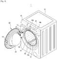
- FIG. 1 is a perspective view of a drum washing machine having a door according to an embodiment of the present disclosure
- a drum washing machine 1 may include a cabinet 10 forming the outer appearance, a tub (not shown) installed in the inside of the cabinet 10 and configured to store washing water, and a cylindrical drum 12 rotatably installed in the inside of the tub, wherein a plurality of dehydrating holes are formed in the wall of the cylindrical drum 12.
- an opening 13 may be formed to enable a user to put or take laundry into or out of the inside of the tub (not shown) and the drum 12.
- the opening 13 may be opened or closed by a door 20 installed on the front panel 11 of the cabinet 10.
- a door contact member 14 contacting the door 20 when the door 20 closes the opening 13 may be provided.
- the door contact member 14 may be recessed in the inside direction of the drum washing machine 1, and formed along the border of the opening 13.
- the door contact member 14 may be formed to correspond to the shape of the door 20. Accordingly, a part protruding with respect to the surface of the cabinet 10 when the door 20 closes can be minimized, which leads to improvement of the beauty of the drum washing machine 1.
- a hinge assembly installing part 17 for installing the hinge assembly 30 which will be described later may be provided.
- a water supply pipe for supplying washing water to the inside of the tub may be installed in the top of the tub, wherein one end of the water supply pipe may connect to a water supply valve, and the other end of the water supply pipe may connect to a detergent case 15.
- the detergent case 15 may connect to the drum 12 through a connection pipe, and water supplied through the water supply pipe may pass through the detergent case 15 and be supplied to the inside of the drum 12 together with detergent.
- an opening may be formed to put or take laundry into or out of the inside of the drum 12, and in the rear portion of the drum 12, a motor (not shown) for driving the drum 12 may be provided.
- a drain unit (not shown) may be provided to discharge washing water filled in the inside of the tub to the outside of the drum washing machine 1.
- the drain unit may include a drain pump (not shown), a connection hose (not shown) connecting the tub to the drain pump to introduce water filled in the inside of the tub to the drain pump, and a drain hose (not shown) to guide water pumped by the drain pump to the outside of the drum washing machine 1.
- control panel 16 may be provided in the upper portion of the front panel 11 of the cabinet 10.
- the control panel 16 may include a display window 16b to display the state of the drum washing machine 1, and an operating unit 16a to enable a user to control operations of the drum washing machine 1.
- the door 20 may include a door frame 21 forming the outer appearance of the drum washing machine 1, and a door glass 22 coupled with the rear portion of the door frame 21 and inserted into the inside of the opening 13 of the cabinet 10.
- the door glass 22 may be configured to show the inside of the drum 12 in order for the user to be able to check laundry process with his/her naked eyes.
- the door glass 22 may preferably protrude in the rear direction of the cabinet 10.
- the door frame 21 may include a hinge assembly 30 to couple the door 20 with the cabinet 10.
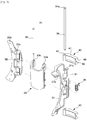
- FIG. 2 is a perspective view schematically showing a hinge assembly according to an embodiment of the present disclosure
- FIG. 3 is an exploded perspective view showing a reinforcement member and a hinge assembly according to an embodiment of the present disclosure
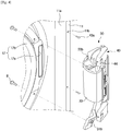
- FIG. 4 is a perspective view showing coupling of a cabinet and a hinge assembly according to an embodiment of the present disclosure
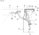
- FIG. 5 is a perspective view showing coupling of a cabinet and a reinforcement member of a hinge assembly according to an embodiment of the present disclosure.
- a hinge assembly 30 for connecting the door 20 rotatably with respect to the cabinet 10 may include a first bracket 31 coupled with the cabinet 10, a second bracket 32 coupled with the door 20, and a connection unit 33 connecting the first bracket 31 with the second bracket 32 and configured to rotate the door 20 in the front direction with respect to the cabinet 10.
- the first bracket 31 may be coupled with the cabinet 10 through the hinge assembly installing part 17 formed in the front panel 11 of the cabinet 10.
- the hinge assembly installing part 17 may be disposed in an area of the door contact member 14, and include a first installing part 17a through which the connection unit 33 passes, and a second installing part 17b which the first bracket 31 is coupled with and fixed at.
- the first installing part 17a may preferably correspond to or be larger than the size of the connection unit 33 so that the connection unit 33 can pass through the first installing part 17a and rotate.
- the second installing part 17b may be configured to couple the first bracket 31 with the front panel 11. There may be formed two second installing parts 17b above and below the first installing part 17a. A bolt B may be inserted into the second installing part 17b and fixed.
- an assembly hole 31b may be formed to assemble the bolt B to be fixed at the second installing part 17b.
- a hinge shaft hole 31a may be formed with which a hinge shaft 34 is coupled.
- the hinge shaft 34 passing through the hinge shaft hole 31 a of the first bracket 31 may include the connection unit 33 and an elastic member 36 connected to the center portion.
- the elastic member 36 may support the hinge shaft 34 and the connection unit 33, and guide the movement of the connection unit 33.
- a door support part 32b installed on and supported by the door frame 21 of the door 20, and a rotation shaft hole 32a with which a rotation shaft 35 for rotatably supporting the door 20 is coupled may be formed.
- a second bracket installing part 21 a on which the second bracket 32 is installed may be formed.
- connection unit 33 a first coupling hole 33a coupled with the hinge shaft 34 of the first bracket 31, and a second coupling hole 33b coupled with the rotation shaft 35 of the second bracket 32 may be respectively formed.
- connection unit 33 may be connected to the hinge shaft 34 of the first bracket 31 fixed on the rear surface 11 a of the cabinet 10, and the other end of the connection unit 33 may be connected to the rotation shaft 35 of the second bracket 32 fixed on the door frame 21 of the door 20.
- the door 20 may rotate with respect to the hinge shaft 34 rotatably fixed at one end of the connection unit 33, and may rotate by the rotation of the rotation shaft 35 coupled with the other end of the connection unit 33.
- the door 20 may rotate in a front-back direction with respect to the opening 13 by the connection unit 33 moving horizontally with respect to the hinge shaft 34 of the hinge assembly 30, thus opening or closing the opening 13.
- a reinforcement member 40 for supporting the cabinet 10 and the hinge assembly 30 may be provided.
- the reinforcement member 40 may have one end rotatably coupled with the hinge shaft 34 of the hinge assembly 30, and may be supported and fixed on the rear surface 11 a of the cabinet 10.
- the reinforcement member 40 may include a body 41, a hinge shaft coupling hole 42 which is formed at one end of the body 41 and into which the hinge shaft 34 is inserted, and a fixing part 43 formed at the other end of the body 41 to fix the reinforcement member 40 at the cabinet 10.
- a support rib 44 may be formed to improve contact to the rear surface 11 a of the cabinet 10.
- the support rib 44 may reinforce the strength of the reinforcement member 40.
- the fixing part 43 of the reinforcement member 40 may be formed in one end of the body 41, and may be fixed by a fixing member 43a such as a bolt penetrating the fixing hole 11 b formed in the front panel 11 of the cabinet 10.
- the fixing part 43 of the reinforcement member 40 is fixed on the cabinet 10 by the fixing member 43a penetrating the fixing hole 11b, however, the concept of the present disclosure is not limited to this.
- the reinforcement member 40 may be fixed by a screw, a rivet, welding, coking, thermosetting, etc.
- a pair of reinforcement members 40 may be respectively installed at the upper and lower portions of the hinge shaft 34, and the hinge shaft 34 may include stoppers 34a protruding outward in order to prevent the reinforcement members 40 from being separated or deviating from the hinge shaft 34.
- the first bracket 31 of the hinge assembly 30 may be fixed using the bolt B at the second installing part 17b of the hinge assembly installing part 17 formed in the rear surface 11 a of the front panel 11.
- connection unit 33 may pass through the first installing part 17a.
- the reinforcement member 40 of the hinge shaft 34 may be disposed toward the first bracket 31.
- the reinforcement member 40 may rotate with respect to the rotation shaft 35 to contact the rear surface 11 a of the front panel 11, and the reinforcement member 40 may be fixed on the front panel 11 through the fixing hole 11 b of the front panel 11.
- the hinge assembly 30 further includes a front panel fixing part through the fixing part 43 of the reinforcement member 40 in addition to a front panel fixing part through the assembly hole 31 b of the first bracket 31, load applied to the hinge assembly 30 can be distributed, and accordingly, deformation can be prevented.
- the second coupling hole 33b of the connection unit 33 may be coupled with the second bracket 32 using the rotation shaft 35.
- Fixing the reinforcement member 40 at the front panel 11 and fixing the second bracket 32 at the door 20 may be performed in this order or in the reverse order.
Landscapes
- Engineering & Computer Science (AREA)
- Textile Engineering (AREA)
- Mechanical Engineering (AREA)
- Main Body Construction Of Washing Machines And Laundry Dryers (AREA)
Abstract
Description
- The present disclosure relates to a drum washing machine, and more particularly, to a drum washing machine having an improved coupling structure of a door and a cabinet.
- In general, a washing machine is equipment of washing laundry by rotating a cylindrical rotating tub in which laundry and washing water are contained. Kinds of washing machines include a drum washing machine and a vertical axis type washing machine. In the drum washing machine, a rotating tub is positioned horizontally, and the rotating tub rotates in a forward direction with respect to the horizontal axis to raise laundry upward along the inner circumference surface and drop the laundry downward to thereby wash the laundry. In the vertical axis type washing machine, a rotating tub with pulsators therein is positioned vertically, and the rotating tub rotates in a forward direction with respect to the vertical axis so as for the pulsators to generate a stream of water, thereby washing laundry using the stream of water.
- The drum washing machine includes a cabinet forming the outer appearance, a cylindrical tub which is installed in the inside of the cabinet and in which washing water is contained, a drum rotatably installed in the inside of the tub to wash laundry, a driving motor disposed behind the tub and configured to rotate the drum, and a door disposed in the front portion of the cabinet. In at least one part of the cabinet, an inlet communicating with the drum is provided, and the door opens and closes the inlet.
- Typically, a structure of rotating the door to open the inlet is used. However, in this case, if the size of the door is large, the door could not open completely.
- Also, the door is fixed on the frame of the cabinet by a hinge assembly, and due to the weight of the door and the friction generated when the door opens and closes, abrasion and deformation occur.
- An aspect of the present disclosure is to provide a drum washing machine having an improved coupling structure of a door and a cabinet.
- Another aspect of the present disclosure is to provide a drum washing machine including a reinforcement member for reinforcing the strength of a hinge assembly.
- Still another aspect of the present disclosure is to provide a drum washing machine capable of improving workability when a hinge assembly is installed.
- In accordance with an aspect of the present disclosure, there is provided a drum washing machine comprising: a cabinet forming an outer appearance of the drum washing machine, and having an opening into which laundry is put; a door configured to open and close the opening of the cabinet; a hinge assembly including a hinge shaft to support the door such that the door is rotatable with respect to the cabinet; and an reinforcement member configured to support the cabinet and the hinge assembly, and rotatably connected to the hinge shaft.
- Also, the drum washing machine according to
claim 1, wherein the reinforcement member is rotatably coupled with the hinge shaft, and supported and fixed on the rear surface of the cabinet. - Also, the drum washing machine according to
claim 1, wherein the reinforcement member comprises: a body; a hinge shaft coupling hole formed in one end of the body, and configured to pass the hinge shaft therethrough; and a fixing part formed at the other end of the body, and configured to fix the reinforcement member at the cabinet. - Also, the drum washing machine according to claim 3, wherein the fixing part comprises a screw, a rivet, welding, coking, and thermosetting.
- Also, the drum washing machine according to claim 3, wherein the body further comprises a support rib formed on an outer circumference surface of the body, and configured to contact and support the cabinet.
- Also, the drum washing machine according to
claim 1, wherein a pair of reinforcement members are disposed at upper and lower portions of the hinge shaft. - Also, the drum washing machine according to
claim 1, wherein the hinge assembly comprises: a first bracket coupled with the cabinet; a second bracket coupled with the door; and a connection unit rotatably connecting the first bracket with the second bracket, wherein the first bracket is coupled with the hinge shaft. - Also, the drum washing machine according to claim 7, wherein one end of the connection unit is connected to the hinge shaft of the first bracket, and the other end of the connection unit is connected to the second bracket.
- Also, the drum washing machine according to claim 8, wherein the second bracket comprises a rotation shaft for rotating the door, and
the connection unit is connected to the rotation shaft. - In accordance with another aspect of the present disclosure, a drum washing machine including a door rotatably coupled by a hinge assembly to open and close an opening formed in at least one part of a cabinet, wherein the hinge assembly comprises: a first bracket coupled with the cabinet; a second bracket coupled with the door;a connection unit having one end coupled with the first bracket by a hinge shaft, and the other end rotatably connected to the second bracket; and a reinforcement member having one end rotatably connected to the hinge shaft, and the other end fixed on the cabinet.
- Also, The drum washing machine according to
claim 10, wherein the reinforcement member comprises: a body; a hinge shaft coupling hole formed at one end of the body, and configured to pass the hinge shaft therethrough; and a fixing part formed at the other end of the body, and configured to fix the reinforcement member at the cabinet. - Also, the drum washing machine according to
claim 11, wherein the fixing part of the reinforcement member comprises a screw, a rivet, welding, coking, and thermosetting. - Also, the drum washing machine according to
claim 11, wherein the body further comprises a support rib formed on an outer circumference surface of the body, and configured to contact and support the cabinet. - According to an embodiment of the present disclosure, by improving a coupling structure of the cabinet and the door, the door can be prevented from drooping and being deformed, resulting in an improvement of product quality.
- Also, since the strength of the hinge assembly fixed on the cabinet can be reinforced by the reinforcement member, and the reinforcement member can rotate with respect to the hinge shaft to be installed on the cabinet, installability and workability can be improved.
-
-
FIG. 1 is a perspective view of a drum washing machine having a door according to an embodiment of the present disclosure. -
FIG. 2 is a perspective view schematically showing a hinge assembly according to an embodiment of the present disclosure. -
FIG. 3 is an exploded perspective view showing a reinforcement member and a hinge assembly according to an embodiment of the present disclosure. -
FIG. 4 is a perspective view showing coupling of a cabinet and a hinge assembly according to an embodiment of the present disclosure. -
FIG. 5 is a perspective view showing coupling of a cabinet and a reinforcement member of a hinge assembly according to an embodiment of the present disclosure. - Hereinafter, embodiments of the present disclosure will be described in detail with reference to the accompanying drawings.
-
FIG. 1 is a perspective view of a drum washing machine having a door according to an embodiment of the present disclosure; - As shown in
FIG. 1 , adrum washing machine 1 may include acabinet 10 forming the outer appearance, a tub (not shown) installed in the inside of thecabinet 10 and configured to store washing water, and acylindrical drum 12 rotatably installed in the inside of the tub, wherein a plurality of dehydrating holes are formed in the wall of thecylindrical drum 12. - In a
front panel 11 disposed in the front portion of thecabinet 10, anopening 13 may be formed to enable a user to put or take laundry into or out of the inside of the tub (not shown) and thedrum 12. The opening 13 may be opened or closed by adoor 20 installed on thefront panel 11 of thecabinet 10. - In the
front panel 11 of thecabinet 10, adoor contact member 14 contacting thedoor 20 when thedoor 20 closes theopening 13 may be provided. Thedoor contact member 14 may be recessed in the inside direction of thedrum washing machine 1, and formed along the border of the opening 13. - Also, the
door contact member 14 may be formed to correspond to the shape of thedoor 20. Accordingly, a part protruding with respect to the surface of thecabinet 10 when thedoor 20 closes can be minimized, which leads to improvement of the beauty of thedrum washing machine 1. - Also, at a part of the
door contact member 14, a hingeassembly installing part 17 for installing thehinge assembly 30 which will be described later may be provided. - Meanwhile, although not shown in
FIG. 1 , a water supply pipe for supplying washing water to the inside of the tub may be installed in the top of the tub, wherein one end of the water supply pipe may connect to a water supply valve, and the other end of the water supply pipe may connect to adetergent case 15. - The
detergent case 15 may connect to thedrum 12 through a connection pipe, and water supplied through the water supply pipe may pass through thedetergent case 15 and be supplied to the inside of thedrum 12 together with detergent. - In the front portion of the
drum 12, an opening may be formed to put or take laundry into or out of the inside of thedrum 12, and in the rear portion of thedrum 12, a motor (not shown) for driving thedrum 12 may be provided. - In the lower portion of the
cabinet 10, a drain unit (not shown) may be provided to discharge washing water filled in the inside of the tub to the outside of thedrum washing machine 1. The drain unit may include a drain pump (not shown), a connection hose (not shown) connecting the tub to the drain pump to introduce water filled in the inside of the tub to the drain pump, and a drain hose (not shown) to guide water pumped by the drain pump to the outside of thedrum washing machine 1. - In the upper portion of the
front panel 11 of thecabinet 10, acontrol panel 16 may be provided. Thecontrol panel 16 may include adisplay window 16b to display the state of thedrum washing machine 1, and anoperating unit 16a to enable a user to control operations of thedrum washing machine 1. - The
door 20 may include adoor frame 21 forming the outer appearance of thedrum washing machine 1, and adoor glass 22 coupled with the rear portion of thedoor frame 21 and inserted into the inside of theopening 13 of thecabinet 10. - The
door glass 22 may be configured to show the inside of thedrum 12 in order for the user to be able to check laundry process with his/her naked eyes. Thedoor glass 22 may preferably protrude in the rear direction of thecabinet 10. - The
door frame 21 may include ahinge assembly 30 to couple thedoor 20 with thecabinet 10. -
FIG. 2 is a perspective view schematically showing a hinge assembly according to an embodiment of the present disclosure,FIG. 3 is an exploded perspective view showing a reinforcement member and a hinge assembly according to an embodiment of the present disclosure,FIG. 4 is a perspective view showing coupling of a cabinet and a hinge assembly according to an embodiment of the present disclosure, andFIG. 5 is a perspective view showing coupling of a cabinet and a reinforcement member of a hinge assembly according to an embodiment of the present disclosure. - As shown in
FIGS. 2 to 5 , ahinge assembly 30 for connecting thedoor 20 rotatably with respect to thecabinet 10 may include afirst bracket 31 coupled with thecabinet 10, asecond bracket 32 coupled with thedoor 20, and aconnection unit 33 connecting thefirst bracket 31 with thesecond bracket 32 and configured to rotate thedoor 20 in the front direction with respect to thecabinet 10. - The
first bracket 31 may be coupled with thecabinet 10 through the hingeassembly installing part 17 formed in thefront panel 11 of thecabinet 10. - The hinge
assembly installing part 17 may be disposed in an area of thedoor contact member 14, and include afirst installing part 17a through which theconnection unit 33 passes, and asecond installing part 17b which thefirst bracket 31 is coupled with and fixed at. - The
first installing part 17a may preferably correspond to or be larger than the size of theconnection unit 33 so that theconnection unit 33 can pass through the first installingpart 17a and rotate. - The
second installing part 17b may be configured to couple thefirst bracket 31 with thefront panel 11. There may be formed twosecond installing parts 17b above and below the first installingpart 17a. A bolt B may be inserted into thesecond installing part 17b and fixed. - In the
first bracket 31, anassembly hole 31b may be formed to assemble the bolt B to be fixed at thesecond installing part 17b. - In the
first bracket 31, ahinge shaft hole 31a may be formed with which ahinge shaft 34 is coupled. - The
hinge shaft 34 passing through thehinge shaft hole 31 a of thefirst bracket 31 may include theconnection unit 33 and anelastic member 36 connected to the center portion. - The
elastic member 36 may support thehinge shaft 34 and theconnection unit 33, and guide the movement of theconnection unit 33. - In the
second bracket 32, adoor support part 32b installed on and supported by thedoor frame 21 of thedoor 20, and arotation shaft hole 32a with which arotation shaft 35 for rotatably supporting thedoor 20 is coupled may be formed. - In the
door frame 21 of thedoor 20, a secondbracket installing part 21 a on which thesecond bracket 32 is installed may be formed. - Meanwhile, at both ends of the
connection unit 33, afirst coupling hole 33a coupled with thehinge shaft 34 of thefirst bracket 31, and asecond coupling hole 33b coupled with therotation shaft 35 of thesecond bracket 32 may be respectively formed. - One end of the
connection unit 33 may be connected to thehinge shaft 34 of thefirst bracket 31 fixed on therear surface 11 a of thecabinet 10, and the other end of theconnection unit 33 may be connected to therotation shaft 35 of thesecond bracket 32 fixed on thedoor frame 21 of thedoor 20. - Accordingly, the
door 20 may rotate with respect to thehinge shaft 34 rotatably fixed at one end of theconnection unit 33, and may rotate by the rotation of therotation shaft 35 coupled with the other end of theconnection unit 33. - The
door 20 may rotate in a front-back direction with respect to theopening 13 by theconnection unit 33 moving horizontally with respect to thehinge shaft 34 of thehinge assembly 30, thus opening or closing theopening 13. - Meanwhile, in the
hinge shaft 34 of thehinge assembly 30, areinforcement member 40 for supporting thecabinet 10 and thehinge assembly 30 may be provided. - The
reinforcement member 40 may have one end rotatably coupled with thehinge shaft 34 of thehinge assembly 30, and may be supported and fixed on therear surface 11 a of thecabinet 10. - The
reinforcement member 40 may include abody 41, a hingeshaft coupling hole 42 which is formed at one end of thebody 41 and into which thehinge shaft 34 is inserted, and a fixingpart 43 formed at the other end of thebody 41 to fix thereinforcement member 40 at thecabinet 10. - On the outer surface of the
body 41, asupport rib 44 may be formed to improve contact to therear surface 11 a of thecabinet 10. Thesupport rib 44 may reinforce the strength of thereinforcement member 40. - The fixing
part 43 of thereinforcement member 40 may be formed in one end of thebody 41, and may be fixed by a fixingmember 43a such as a bolt penetrating the fixinghole 11 b formed in thefront panel 11 of thecabinet 10. - In the current embodiment, the fixing
part 43 of thereinforcement member 40 is fixed on thecabinet 10 by the fixingmember 43a penetrating the fixinghole 11b, however, the concept of the present disclosure is not limited to this. For example, thereinforcement member 40 may be fixed by a screw, a rivet, welding, coking, thermosetting, etc. - A pair of
reinforcement members 40 may be respectively installed at the upper and lower portions of thehinge shaft 34, and thehinge shaft 34 may includestoppers 34a protruding outward in order to prevent thereinforcement members 40 from being separated or deviating from thehinge shaft 34. - Now, a process of fixing the
hinge assembly 30 on thecabinet 10 will be described with reference toFIGS. 4 and5 . - The
first bracket 31 of thehinge assembly 30 may be fixed using the bolt B at thesecond installing part 17b of the hingeassembly installing part 17 formed in therear surface 11 a of thefront panel 11. - One end of the
connection unit 33 may pass through the first installingpart 17a. - The
reinforcement member 40 of thehinge shaft 34 may be disposed toward thefirst bracket 31. - If the
first bracket 31 is fixed on thefront panel 11, thereinforcement member 40 may rotate with respect to therotation shaft 35 to contact therear surface 11 a of thefront panel 11, and thereinforcement member 40 may be fixed on thefront panel 11 through the fixinghole 11 b of thefront panel 11. - Since the
hinge assembly 30 according to an embodiment of the present disclosure further includes a front panel fixing part through the fixingpart 43 of thereinforcement member 40 in addition to a front panel fixing part through theassembly hole 31 b of thefirst bracket 31, load applied to thehinge assembly 30 can be distributed, and accordingly, deformation can be prevented. - Meanwhile, if the
first bracket 31 is fixed on therear surface 11 a of thefront panel 11, thesecond coupling hole 33b of theconnection unit 33 may be coupled with thesecond bracket 32 using therotation shaft 35. - Fixing the
reinforcement member 40 at thefront panel 11 and fixing thesecond bracket 32 at thedoor 20 may be performed in this order or in the reverse order. - It will be apparent to those skilled in the art that various modifications and variations can be made in the present disclosure without departing from the spirit or scope of the disclosures. Thus, it is intended that the present disclosure covers the modifications and variations of this disclosure provided they come within the scope of the appended claims and their equivalents.
Claims (13)
- A drum washing machine comprising:a cabinet forming an outer appearance of the drum washing machine, and having an opening into which laundry is put;a door configured to open and close the opening of the cabinet;a hinge assembly including a hinge shaft to support the door such that the door is rotatable with respect to the cabinet; andan reinforcement member configured to support the cabinet and the hinge assembly, and rotatably connected to the hinge shaft.
- The drum washing machine according to claim 1, wherein the reinforcement member is rotatably coupled with the hinge shaft, and supported and fixed on the rear surface of the cabinet.
- The drum washing machine according to claim 1, wherein the reinforcement member comprises:a body;a hinge shaft coupling hole formed in one end of the body, and configured to pass the hinge shaft therethrough; anda fixing part formed at the other end of the body, and configured to fix the reinforcement member at the cabinet.
- The drum washing machine according to claim 3, wherein the fixing part comprises a screw, a rivet, welding, coking, and thermosetting.
- The drum washing machine according to claim 3, wherein the body further comprises a support rib formed on an outer circumference surface of the body, and configured to contact and support the cabinet.
- The drum washing machine according to claim 1, wherein a pair of reinforcement members are disposed at upper and lower portions of the hinge shaft.
- The drum washing machine according to claim 1, wherein the hinge assembly comprises:a first bracket coupled with the cabinet;a second bracket coupled with the door; anda connection unit rotatably connecting the first bracket with the second bracket,wherein the first bracket is coupled with the hinge shaft.
- The drum washing machine according to claim 7, wherein one end of the connection unit is connected to the hinge shaft of the first bracket, and the other end of the connection unit is connected to the second bracket.
- The drum washing machine according to claim 8, wherein the second bracket comprises a rotation shaft for rotating the door, and
the connection unit is connected to the rotation shaft. - A drum washing machine including a door rotatably coupled by a hinge assembly to open and close an opening formed in at least one part of a cabinet, wherein the hinge assembly comprises:a first bracket coupled with the cabinet;a second bracket coupled with the door;a connection unit having one end coupled with the first bracket by a hinge shaft, and the other end rotatably connected to the second bracket; anda reinforcement member having one end rotatably connected to the hinge shaft, and the other end fixed on the cabinet.
- The drum washing machine according to claim 10, wherein the reinforcement member comprises:a body;a hinge shaft coupling hole formed at one end of the body, and configured to pass the hinge shaft therethrough; anda fixing part formed at the other end of the body, and configured to fix the reinforcement member at the cabinet.
- The drum washing machine according to claim 11, wherein the fixing part of the reinforcement member comprises a screw, a rivet, welding, coking, and thermosetting.
- The drum washing machine according to claim 11, wherein the body further comprises a support rib formed on an outer circumference surface of the body, and configured to contact and support the cabinet.
Applications Claiming Priority (2)
| Application Number | Priority Date | Filing Date | Title |
|---|---|---|---|
| KR1020140036447A KR102219934B1 (en) | 2014-03-28 | 2014-03-28 | Drum Washing Machine |
| PCT/KR2015/002674 WO2015147481A1 (en) | 2014-03-28 | 2015-03-19 | Drum washing machine |
Publications (3)
| Publication Number | Publication Date |
|---|---|
| EP3124669A1 true EP3124669A1 (en) | 2017-02-01 |
| EP3124669A4 EP3124669A4 (en) | 2018-01-17 |
| EP3124669B1 EP3124669B1 (en) | 2020-08-19 |
Family
ID=54195937
Family Applications (1)
| Application Number | Title | Priority Date | Filing Date |
|---|---|---|---|
| EP15768094.3A Active EP3124669B1 (en) | 2014-03-28 | 2015-03-19 | Drum washing machine |
Country Status (5)
| Country | Link |
|---|---|
| US (1) | US10450691B2 (en) |
| EP (1) | EP3124669B1 (en) |
| KR (1) | KR102219934B1 (en) |
| CN (1) | CN106103831B (en) |
| WO (1) | WO2015147481A1 (en) |
Cited By (3)
| Publication number | Priority date | Publication date | Assignee | Title |
|---|---|---|---|---|
| EP3653780A1 (en) | 2018-11-15 | 2020-05-20 | Groupe Brandt | Household appliance comprising a body, a door and a linking device connecting the door to the body |
| DE102022208895A1 (en) | 2022-08-29 | 2024-02-29 | BSH Hausgeräte GmbH | Laundry care device for caring for items |
| DE102023202692A1 (en) | 2023-03-24 | 2024-09-26 | BSH Hausgeräte GmbH | Household appliance with defined locking positions for an open access door |
Families Citing this family (8)
| Publication number | Priority date | Publication date | Assignee | Title |
|---|---|---|---|---|
| KR102415396B1 (en) * | 2015-07-22 | 2022-06-30 | 삼성전자주식회사 | Washing machine |
| CN107012646B (en) * | 2016-01-28 | 2023-07-28 | 无锡小天鹅电器有限公司 | Movable drum washing machine with clothes taking and putting opening |
| CN107385772A (en) * | 2017-08-02 | 2017-11-24 | 无锡小天鹅股份有限公司 | The control device and washing machine of washing machine |
| CN109778503B (en) * | 2017-11-15 | 2022-08-05 | 佛山海尔滚筒洗衣机有限公司 | Hinge fixed knot constructs and washing machine |
| WO2019107857A1 (en) * | 2017-11-28 | 2019-06-06 | 엘지전자 주식회사 | Clothing treatment device |
| CN110158286A (en) * | 2018-02-13 | 2019-08-23 | 青岛海尔滚筒洗衣机有限公司 | A kind of door hinge components and clothes treatment device |
| CN110241577B (en) * | 2018-03-07 | 2024-04-30 | 松下家电(中国)有限公司 | Hinge and clothes treating apparatus |
| EP3623524B1 (en) * | 2018-09-17 | 2021-05-19 | Candy S.p.A. | Door-hinge assembly in a washing machine |
Family Cites Families (36)
| Publication number | Priority date | Publication date | Assignee | Title |
|---|---|---|---|---|
| US2284320A (en) * | 1939-10-23 | 1942-05-26 | Earl E Howe | Hinge guard |
| US2309001A (en) * | 1939-12-22 | 1943-01-19 | Servel Inc | Refrigerator |
| US2319600A (en) * | 1940-05-16 | 1943-05-18 | Servel Inc | Refrigerator structure |
| US2578610A (en) * | 1946-02-01 | 1951-12-11 | Nat Lock Co | Cabinet hinge |
| US3066349A (en) * | 1961-07-07 | 1962-12-04 | Ted L Youngdale | Hinge |
| US3378880A (en) * | 1965-09-29 | 1968-04-23 | Gen Electric | Combined hinging and holding device for closure members |
| IT969759B (en) * | 1972-10-20 | 1974-04-10 | San Giorgio Elettrodomesti | MACHINE FOR TREATING BIANCHEPIA ON WHICH A COMPONENT WITH ELECTRIC CONTROL IS MOUNTED ON THE LOADING DOOR |
| GB9122079D0 (en) * | 1991-10-17 | 1991-11-27 | J E S Arnold Domestic Applianc | A door for a domestic electrical appliance |
| US5685046A (en) * | 1996-04-12 | 1997-11-11 | Chrysler Corporation | Motor vehicle double pivot hinge |
| US6196617B1 (en) * | 1997-09-30 | 2001-03-06 | Krystal Koach, Inc. | Rear door structure for a vehicle |
| IT1311136B1 (en) | 1999-11-08 | 2002-03-04 | Cmi Srl | HINGE DEVICE WITH OPENING - TWO-STAGE CLOSING FOR THE DOOR OF HOUSEHOLD APPLIANCES, IN PARTICULAR WASHING MACHINES. |
| KR200202030Y1 (en) * | 2000-05-30 | 2000-11-01 | 박창수 | Hinge |
| KR100484795B1 (en) * | 2002-01-09 | 2005-04-22 | 엘지전자 주식회사 | The Door of A Drum Washer |
| WO2003057971A1 (en) * | 2002-01-09 | 2003-07-17 | Lg Electronics Inc. | Door for washing machine and dryer and washing machine and dryer having the same |
| KR100425126B1 (en) * | 2002-03-13 | 2004-03-30 | 엘지전자 주식회사 | Device for linking case to door in drum type washing machine and method for assembling the same |
| JP3801167B2 (en) * | 2003-11-14 | 2006-07-26 | 松下電器産業株式会社 | Drum washing machine |
| US20050204510A1 (en) * | 2004-03-18 | 2005-09-22 | Maytag Corporation | Hidden hinge with 270 degree rotation |
| KR101034197B1 (en) * | 2004-09-20 | 2011-05-16 | 삼성전자주식회사 | Clothes Drying Machine |
| KR100676814B1 (en) * | 2005-04-04 | 2007-02-01 | 삼성전자주식회사 | Multi function device |
| JP4508992B2 (en) * | 2005-09-13 | 2010-07-21 | キヤノン株式会社 | Sheet conveying apparatus and image forming apparatus |
| KR20070037044A (en) * | 2005-09-30 | 2007-04-04 | 엘지전자 주식회사 | Hinge assembly for door of washing machine |
| US7617570B2 (en) * | 2006-03-22 | 2009-11-17 | Whirlpool Corporation | Double-pivot, constrained kinematic hinge for a front-loading laundry machine |
| KR100845290B1 (en) * | 2007-04-05 | 2008-07-09 | 삼성전자주식회사 | Drum type washing machine |
| CA2610078A1 (en) * | 2007-11-09 | 2009-05-09 | Mabe Canada Inc. | Clothes dryer door hinge |
| EP2077349B1 (en) * | 2007-12-31 | 2014-12-10 | Electrolux Home Products Corporation N.V. | Electric household appliance |
| KR101467765B1 (en) * | 2008-03-13 | 2014-12-03 | 엘지전자 주식회사 | Laundry Treating Apparatus |
| US8201304B2 (en) * | 2009-02-25 | 2012-06-19 | General Electric Company | Compliant door hinge |
| JP4913835B2 (en) * | 2009-03-04 | 2012-04-11 | 日立アプライアンス株式会社 | Drum washing machine |
| US8733863B2 (en) * | 2009-07-30 | 2014-05-27 | Lg Electronics Inc. | Washing machine |
| KR20110057920A (en) * | 2009-11-25 | 2011-06-01 | 삼성전자주식회사 | Drum washing machine |
| BR112013017082B1 (en) * | 2011-02-24 | 2021-05-11 | Lg Electronics Inc | garment care apparatus |
| KR20120097307A (en) * | 2011-02-24 | 2012-09-03 | 엘지전자 주식회사 | Laundry machine |
| US8936331B2 (en) * | 2012-02-21 | 2015-01-20 | General Electric Company | Hinge for an appliance |
| US8857928B2 (en) * | 2012-03-08 | 2014-10-14 | General Electric Company | Appliance with a bracket for supporting a hinge |
| KR102086384B1 (en) * | 2013-06-19 | 2020-03-09 | 삼성전자주식회사 | Door Hinge Device and Drum Washing Machine Having the Same |
| US9523225B2 (en) * | 2014-03-17 | 2016-12-20 | Austin Hardware And Supply, Inc. | Concealed hinge |
-
2014
- 2014-03-28 KR KR1020140036447A patent/KR102219934B1/en active IP Right Grant
-
2015
- 2015-03-19 US US15/300,260 patent/US10450691B2/en active Active
- 2015-03-19 EP EP15768094.3A patent/EP3124669B1/en active Active
- 2015-03-19 WO PCT/KR2015/002674 patent/WO2015147481A1/en active Application Filing
- 2015-03-19 CN CN201580012728.9A patent/CN106103831B/en active Active
Cited By (5)
| Publication number | Priority date | Publication date | Assignee | Title |
|---|---|---|---|---|
| EP3653780A1 (en) | 2018-11-15 | 2020-05-20 | Groupe Brandt | Household appliance comprising a body, a door and a linking device connecting the door to the body |
| FR3088654A1 (en) | 2018-11-15 | 2020-05-22 | Groupe Brandt | HOUSEHOLD APPLIANCE COMPRISING A BODY, A DOOR AND A CONNECTING DEVICE CONNECTING THE DOOR TO THE BODY |
| DE102022208895A1 (en) | 2022-08-29 | 2024-02-29 | BSH Hausgeräte GmbH | Laundry care device for caring for items |
| EP4332293A1 (en) | 2022-08-29 | 2024-03-06 | BSH Hausgeräte GmbH | Laundry care appliance for the care of objects |
| DE102023202692A1 (en) | 2023-03-24 | 2024-09-26 | BSH Hausgeräte GmbH | Household appliance with defined locking positions for an open access door |
Also Published As
| Publication number | Publication date |
|---|---|
| CN106103831B (en) | 2019-11-15 |
| WO2015147481A1 (en) | 2015-10-01 |
| KR20150112386A (en) | 2015-10-07 |
| US10450691B2 (en) | 2019-10-22 |
| KR102219934B1 (en) | 2021-02-25 |
| US20170137989A1 (en) | 2017-05-18 |
| EP3124669B1 (en) | 2020-08-19 |
| CN106103831A (en) | 2016-11-09 |
| EP3124669A4 (en) | 2018-01-17 |
Similar Documents
| Publication | Publication Date | Title |
|---|---|---|
| EP3124669B1 (en) | Drum washing machine | |
| EP3339498B1 (en) | Washing machine | |
| KR102642290B1 (en) | Washing machine | |
| CA2956138A1 (en) | Laundry treatment apparatus | |
| US20180179682A1 (en) | Washing machine | |
| EP3372723B1 (en) | Washing machine | |
| US20180179690A1 (en) | Washing machine | |
| KR102639680B1 (en) | Washing machine | |
| US20230323588A1 (en) | Washing machine | |
| KR102543851B1 (en) | Washing machine | |
| EP3339497B1 (en) | Washing machine | |
| EP3543389A2 (en) | Washing machine | |
| US11913161B2 (en) | Washing machine | |
| EP3372726A1 (en) | Apparatus for treating laundry | |
| KR101661977B1 (en) | Washing machine | |
| KR20110086419A (en) | A laundry treatment machine |
Legal Events
| Date | Code | Title | Description |
|---|---|---|---|
| STAA | Information on the status of an ep patent application or granted ep patent |
Free format text: STATUS: THE INTERNATIONAL PUBLICATION HAS BEEN MADE |
|
| PUAI | Public reference made under article 153(3) epc to a published international application that has entered the european phase |
Free format text: ORIGINAL CODE: 0009012 |
|
| STAA | Information on the status of an ep patent application or granted ep patent |
Free format text: STATUS: REQUEST FOR EXAMINATION WAS MADE |
|
| 17P | Request for examination filed |
Effective date: 20160826 |
|
| AK | Designated contracting states |
Kind code of ref document: A1 Designated state(s): AL AT BE BG CH CY CZ DE DK EE ES FI FR GB GR HR HU IE IS IT LI LT LU LV MC MK MT NL NO PL PT RO RS SE SI SK SM TR |
|
| AX | Request for extension of the european patent |
Extension state: BA ME |
|
| DAV | Request for validation of the european patent (deleted) | ||
| DAX | Request for extension of the european patent (deleted) | ||
| RIC1 | Information provided on ipc code assigned before grant |
Ipc: D06F 37/10 20060101AFI20171206BHEP Ipc: D06F 39/14 20060101ALI20171206BHEP Ipc: D06F 37/02 20060101ALI20171206BHEP Ipc: E05D 3/12 20060101ALN20171206BHEP Ipc: E05D 7/00 20060101ALN20171206BHEP |
|
| A4 | Supplementary search report drawn up and despatched |
Effective date: 20171214 |
|
| STAA | Information on the status of an ep patent application or granted ep patent |
Free format text: STATUS: EXAMINATION IS IN PROGRESS |
|
| 17Q | First examination report despatched |
Effective date: 20190411 |
|
| RIC1 | Information provided on ipc code assigned before grant |
Ipc: D06F 39/14 20060101ALI20191115BHEP Ipc: D06F 37/02 20060101ALI20191115BHEP Ipc: D06F 37/10 20060101AFI20191115BHEP Ipc: E05D 7/00 20060101ALN20191115BHEP Ipc: E05D 3/12 20060101ALN20191115BHEP |
|
| RIC1 | Information provided on ipc code assigned before grant |
Ipc: D06F 37/02 20060101ALI20191125BHEP Ipc: E05D 7/00 20060101ALN20191125BHEP Ipc: D06F 37/10 20060101AFI20191125BHEP Ipc: E05D 3/12 20060101ALN20191125BHEP Ipc: D06F 39/14 20060101ALI20191125BHEP |
|
| GRAP | Despatch of communication of intention to grant a patent |
Free format text: ORIGINAL CODE: EPIDOSNIGR1 |
|
| STAA | Information on the status of an ep patent application or granted ep patent |
Free format text: STATUS: GRANT OF PATENT IS INTENDED |
|
| RIC1 | Information provided on ipc code assigned before grant |
Ipc: D06F 37/02 20060101ALI20200210BHEP Ipc: D06F 37/10 20060101AFI20200210BHEP Ipc: E05D 3/12 20060101ALN20200210BHEP Ipc: E05D 7/00 20060101ALN20200210BHEP Ipc: D06F 39/14 20060101ALI20200210BHEP |
|
| RIC1 | Information provided on ipc code assigned before grant |
Ipc: D06F 37/02 20060101ALI20200214BHEP Ipc: D06F 37/10 20060101AFI20200214BHEP Ipc: D06F 39/14 20060101ALI20200214BHEP Ipc: E05D 3/12 20060101ALN20200214BHEP Ipc: E05D 7/00 20060101ALN20200214BHEP |
|
| INTG | Intention to grant announced |
Effective date: 20200309 |
|
| GRAS | Grant fee paid |
Free format text: ORIGINAL CODE: EPIDOSNIGR3 |
|
| GRAA | (expected) grant |
Free format text: ORIGINAL CODE: 0009210 |
|
| STAA | Information on the status of an ep patent application or granted ep patent |
Free format text: STATUS: THE PATENT HAS BEEN GRANTED |
|
| AK | Designated contracting states |
Kind code of ref document: B1 Designated state(s): AL AT BE BG CH CY CZ DE DK EE ES FI FR GB GR HR HU IE IS IT LI LT LU LV MC MK MT NL NO PL PT RO RS SE SI SK SM TR |
|
| REG | Reference to a national code |
Ref country code: CH Ref legal event code: EP |
|
| REG | Reference to a national code |
Ref country code: DE Ref legal event code: R096 Ref document number: 602015057732 Country of ref document: DE |
|
| REG | Reference to a national code |
Ref country code: AT Ref legal event code: REF Ref document number: 1304057 Country of ref document: AT Kind code of ref document: T Effective date: 20200915 |
|
| REG | Reference to a national code |
Ref country code: IE Ref legal event code: FG4D |
|
| REG | Reference to a national code |
Ref country code: LT Ref legal event code: MG4D |
|
| REG | Reference to a national code |
Ref country code: NL Ref legal event code: MP Effective date: 20200819 |
|
| PG25 | Lapsed in a contracting state [announced via postgrant information from national office to epo] |
Ref country code: HR Free format text: LAPSE BECAUSE OF FAILURE TO SUBMIT A TRANSLATION OF THE DESCRIPTION OR TO PAY THE FEE WITHIN THE PRESCRIBED TIME-LIMIT Effective date: 20200819 Ref country code: BG Free format text: LAPSE BECAUSE OF FAILURE TO SUBMIT A TRANSLATION OF THE DESCRIPTION OR TO PAY THE FEE WITHIN THE PRESCRIBED TIME-LIMIT Effective date: 20201119 Ref country code: SE Free format text: LAPSE BECAUSE OF FAILURE TO SUBMIT A TRANSLATION OF THE DESCRIPTION OR TO PAY THE FEE WITHIN THE PRESCRIBED TIME-LIMIT Effective date: 20200819 Ref country code: GR Free format text: LAPSE BECAUSE OF FAILURE TO SUBMIT A TRANSLATION OF THE DESCRIPTION OR TO PAY THE FEE WITHIN THE PRESCRIBED TIME-LIMIT Effective date: 20201120 Ref country code: LT Free format text: LAPSE BECAUSE OF FAILURE TO SUBMIT A TRANSLATION OF THE DESCRIPTION OR TO PAY THE FEE WITHIN THE PRESCRIBED TIME-LIMIT Effective date: 20200819 Ref country code: FI Free format text: LAPSE BECAUSE OF FAILURE TO SUBMIT A TRANSLATION OF THE DESCRIPTION OR TO PAY THE FEE WITHIN THE PRESCRIBED TIME-LIMIT Effective date: 20200819 Ref country code: PT Free format text: LAPSE BECAUSE OF FAILURE TO SUBMIT A TRANSLATION OF THE DESCRIPTION OR TO PAY THE FEE WITHIN THE PRESCRIBED TIME-LIMIT Effective date: 20201221 Ref country code: NO Free format text: LAPSE BECAUSE OF FAILURE TO SUBMIT A TRANSLATION OF THE DESCRIPTION OR TO PAY THE FEE WITHIN THE PRESCRIBED TIME-LIMIT Effective date: 20201119 |
|
| REG | Reference to a national code |
Ref country code: AT Ref legal event code: MK05 Ref document number: 1304057 Country of ref document: AT Kind code of ref document: T Effective date: 20200819 |
|
| PG25 | Lapsed in a contracting state [announced via postgrant information from national office to epo] |
Ref country code: LV Free format text: LAPSE BECAUSE OF FAILURE TO SUBMIT A TRANSLATION OF THE DESCRIPTION OR TO PAY THE FEE WITHIN THE PRESCRIBED TIME-LIMIT Effective date: 20200819 Ref country code: RS Free format text: LAPSE BECAUSE OF FAILURE TO SUBMIT A TRANSLATION OF THE DESCRIPTION OR TO PAY THE FEE WITHIN THE PRESCRIBED TIME-LIMIT Effective date: 20200819 Ref country code: NL Free format text: LAPSE BECAUSE OF FAILURE TO SUBMIT A TRANSLATION OF THE DESCRIPTION OR TO PAY THE FEE WITHIN THE PRESCRIBED TIME-LIMIT Effective date: 20200819 Ref country code: PL Free format text: LAPSE BECAUSE OF FAILURE TO SUBMIT A TRANSLATION OF THE DESCRIPTION OR TO PAY THE FEE WITHIN THE PRESCRIBED TIME-LIMIT Effective date: 20200819 Ref country code: IS Free format text: LAPSE BECAUSE OF FAILURE TO SUBMIT A TRANSLATION OF THE DESCRIPTION OR TO PAY THE FEE WITHIN THE PRESCRIBED TIME-LIMIT Effective date: 20201219 |
|
| PG25 | Lapsed in a contracting state [announced via postgrant information from national office to epo] |
Ref country code: CZ Free format text: LAPSE BECAUSE OF FAILURE TO SUBMIT A TRANSLATION OF THE DESCRIPTION OR TO PAY THE FEE WITHIN THE PRESCRIBED TIME-LIMIT Effective date: 20200819 Ref country code: DK Free format text: LAPSE BECAUSE OF FAILURE TO SUBMIT A TRANSLATION OF THE DESCRIPTION OR TO PAY THE FEE WITHIN THE PRESCRIBED TIME-LIMIT Effective date: 20200819 Ref country code: SM Free format text: LAPSE BECAUSE OF FAILURE TO SUBMIT A TRANSLATION OF THE DESCRIPTION OR TO PAY THE FEE WITHIN THE PRESCRIBED TIME-LIMIT Effective date: 20200819 Ref country code: RO Free format text: LAPSE BECAUSE OF FAILURE TO SUBMIT A TRANSLATION OF THE DESCRIPTION OR TO PAY THE FEE WITHIN THE PRESCRIBED TIME-LIMIT Effective date: 20200819 Ref country code: EE Free format text: LAPSE BECAUSE OF FAILURE TO SUBMIT A TRANSLATION OF THE DESCRIPTION OR TO PAY THE FEE WITHIN THE PRESCRIBED TIME-LIMIT Effective date: 20200819 |
|
| REG | Reference to a national code |
Ref country code: DE Ref legal event code: R097 Ref document number: 602015057732 Country of ref document: DE |
|
| PG25 | Lapsed in a contracting state [announced via postgrant information from national office to epo] |
Ref country code: ES Free format text: LAPSE BECAUSE OF FAILURE TO SUBMIT A TRANSLATION OF THE DESCRIPTION OR TO PAY THE FEE WITHIN THE PRESCRIBED TIME-LIMIT Effective date: 20200819 Ref country code: AT Free format text: LAPSE BECAUSE OF FAILURE TO SUBMIT A TRANSLATION OF THE DESCRIPTION OR TO PAY THE FEE WITHIN THE PRESCRIBED TIME-LIMIT Effective date: 20200819 Ref country code: AL Free format text: LAPSE BECAUSE OF FAILURE TO SUBMIT A TRANSLATION OF THE DESCRIPTION OR TO PAY THE FEE WITHIN THE PRESCRIBED TIME-LIMIT Effective date: 20200819 |
|
| PLBE | No opposition filed within time limit |
Free format text: ORIGINAL CODE: 0009261 |
|
| STAA | Information on the status of an ep patent application or granted ep patent |
Free format text: STATUS: NO OPPOSITION FILED WITHIN TIME LIMIT |
|
| PG25 | Lapsed in a contracting state [announced via postgrant information from national office to epo] |
Ref country code: SK Free format text: LAPSE BECAUSE OF FAILURE TO SUBMIT A TRANSLATION OF THE DESCRIPTION OR TO PAY THE FEE WITHIN THE PRESCRIBED TIME-LIMIT Effective date: 20200819 |
|
| 26N | No opposition filed |
Effective date: 20210520 |
|
| PG25 | Lapsed in a contracting state [announced via postgrant information from national office to epo] |
Ref country code: IT Free format text: LAPSE BECAUSE OF FAILURE TO SUBMIT A TRANSLATION OF THE DESCRIPTION OR TO PAY THE FEE WITHIN THE PRESCRIBED TIME-LIMIT Effective date: 20200819 |
|
| PG25 | Lapsed in a contracting state [announced via postgrant information from national office to epo] |
Ref country code: SI Free format text: LAPSE BECAUSE OF FAILURE TO SUBMIT A TRANSLATION OF THE DESCRIPTION OR TO PAY THE FEE WITHIN THE PRESCRIBED TIME-LIMIT Effective date: 20200819 |
|
| PG25 | Lapsed in a contracting state [announced via postgrant information from national office to epo] |
Ref country code: MC Free format text: LAPSE BECAUSE OF FAILURE TO SUBMIT A TRANSLATION OF THE DESCRIPTION OR TO PAY THE FEE WITHIN THE PRESCRIBED TIME-LIMIT Effective date: 20200819 |
|
| REG | Reference to a national code |
Ref country code: CH Ref legal event code: PL |
|
| REG | Reference to a national code |
Ref country code: BE Ref legal event code: MM Effective date: 20210331 |
|
| PG25 | Lapsed in a contracting state [announced via postgrant information from national office to epo] |
Ref country code: LI Free format text: LAPSE BECAUSE OF NON-PAYMENT OF DUE FEES Effective date: 20210331 Ref country code: LU Free format text: LAPSE BECAUSE OF NON-PAYMENT OF DUE FEES Effective date: 20210319 Ref country code: CH Free format text: LAPSE BECAUSE OF NON-PAYMENT OF DUE FEES Effective date: 20210331 Ref country code: FR Free format text: LAPSE BECAUSE OF NON-PAYMENT OF DUE FEES Effective date: 20210331 Ref country code: IE Free format text: LAPSE BECAUSE OF NON-PAYMENT OF DUE FEES Effective date: 20210319 |
|
| PG25 | Lapsed in a contracting state [announced via postgrant information from national office to epo] |
Ref country code: BE Free format text: LAPSE BECAUSE OF NON-PAYMENT OF DUE FEES Effective date: 20210331 |
|
| PG25 | Lapsed in a contracting state [announced via postgrant information from national office to epo] |
Ref country code: HU Free format text: LAPSE BECAUSE OF FAILURE TO SUBMIT A TRANSLATION OF THE DESCRIPTION OR TO PAY THE FEE WITHIN THE PRESCRIBED TIME-LIMIT; INVALID AB INITIO Effective date: 20150319 |
|
| PG25 | Lapsed in a contracting state [announced via postgrant information from national office to epo] |
Ref country code: CY Free format text: LAPSE BECAUSE OF FAILURE TO SUBMIT A TRANSLATION OF THE DESCRIPTION OR TO PAY THE FEE WITHIN THE PRESCRIBED TIME-LIMIT Effective date: 20200819 |
|
| PG25 | Lapsed in a contracting state [announced via postgrant information from national office to epo] |
Ref country code: MK Free format text: LAPSE BECAUSE OF FAILURE TO SUBMIT A TRANSLATION OF THE DESCRIPTION OR TO PAY THE FEE WITHIN THE PRESCRIBED TIME-LIMIT Effective date: 20200819 |
|
| PGFP | Annual fee paid to national office [announced via postgrant information from national office to epo] |
Ref country code: DE Payment date: 20240220 Year of fee payment: 10 Ref country code: GB Payment date: 20240220 Year of fee payment: 10 |
|
| PG25 | Lapsed in a contracting state [announced via postgrant information from national office to epo] |
Ref country code: TR Free format text: LAPSE BECAUSE OF FAILURE TO SUBMIT A TRANSLATION OF THE DESCRIPTION OR TO PAY THE FEE WITHIN THE PRESCRIBED TIME-LIMIT Effective date: 20200819 |
|
| PG25 | Lapsed in a contracting state [announced via postgrant information from national office to epo] |
Ref country code: MT Free format text: LAPSE BECAUSE OF FAILURE TO SUBMIT A TRANSLATION OF THE DESCRIPTION OR TO PAY THE FEE WITHIN THE PRESCRIBED TIME-LIMIT Effective date: 20200819 |