EP3124292A1 - Tyre with a wear indicator and system for wear testing - Google Patents
Tyre with a wear indicator and system for wear testing Download PDFInfo
- Publication number
- EP3124292A1 EP3124292A1 EP16001973.3A EP16001973A EP3124292A1 EP 3124292 A1 EP3124292 A1 EP 3124292A1 EP 16001973 A EP16001973 A EP 16001973A EP 3124292 A1 EP3124292 A1 EP 3124292A1
- Authority
- EP
- European Patent Office
- Prior art keywords
- wear
- code
- tire
- pattern
- state
- Prior art date
- Legal status (The legal status is an assumption and is not a legal conclusion. Google has not performed a legal analysis and makes no representation as to the accuracy of the status listed.)
- Granted
Links
- 238000012360 testing method Methods 0.000 title claims description 6
- 239000000969 carrier Substances 0.000 claims description 19
- 239000000463 material Substances 0.000 claims description 15
- 230000001419 dependent effect Effects 0.000 claims description 8
- 239000002872 contrast media Substances 0.000 claims description 4
- 240000001414 Eucalyptus viminalis Species 0.000 claims 1
- 238000000034 method Methods 0.000 description 6
- 230000003287 optical effect Effects 0.000 description 5
- 238000011156 evaluation Methods 0.000 description 4
- 238000004519 manufacturing process Methods 0.000 description 4
- 230000003247 decreasing effect Effects 0.000 description 3
- 238000003780 insertion Methods 0.000 description 2
- 230000037431 insertion Effects 0.000 description 2
- 238000005259 measurement Methods 0.000 description 2
- 238000002679 ablation Methods 0.000 description 1
- 238000013459 approach Methods 0.000 description 1
- 239000003086 colorant Substances 0.000 description 1
- 150000001875 compounds Chemical class 0.000 description 1
- 238000010276 construction Methods 0.000 description 1
- 238000011109 contamination Methods 0.000 description 1
- 230000007423 decrease Effects 0.000 description 1
- 238000001514 detection method Methods 0.000 description 1
- 230000006866 deterioration Effects 0.000 description 1
- 238000005553 drilling Methods 0.000 description 1
- 239000012535 impurity Substances 0.000 description 1
- 238000007373 indentation Methods 0.000 description 1
- 238000001746 injection moulding Methods 0.000 description 1
- 238000003801 milling Methods 0.000 description 1
- 238000012986 modification Methods 0.000 description 1
- 230000004048 modification Effects 0.000 description 1
- 238000012544 monitoring process Methods 0.000 description 1
- 238000003825 pressing Methods 0.000 description 1
- 238000003860 storage Methods 0.000 description 1
- 238000009423 ventilation Methods 0.000 description 1
- 230000000007 visual effect Effects 0.000 description 1
- 238000003466 welding Methods 0.000 description 1
Images


Classifications
-
- G—PHYSICS
- G06—COMPUTING; CALCULATING OR COUNTING
- G06K—GRAPHICAL DATA READING; PRESENTATION OF DATA; RECORD CARRIERS; HANDLING RECORD CARRIERS
- G06K19/00—Record carriers for use with machines and with at least a part designed to carry digital markings
- G06K19/06—Record carriers for use with machines and with at least a part designed to carry digital markings characterised by the kind of the digital marking, e.g. shape, nature, code
- G06K19/06009—Record carriers for use with machines and with at least a part designed to carry digital markings characterised by the kind of the digital marking, e.g. shape, nature, code with optically detectable marking
- G06K19/06046—Constructional details
- G06K19/06159—Constructional details the marking being relief type, e.g. three-dimensional bar codes engraved in a support
-
- B—PERFORMING OPERATIONS; TRANSPORTING
- B60—VEHICLES IN GENERAL
- B60C—VEHICLE TYRES; TYRE INFLATION; TYRE CHANGING; CONNECTING VALVES TO INFLATABLE ELASTIC BODIES IN GENERAL; DEVICES OR ARRANGEMENTS RELATED TO TYRES
- B60C11/00—Tyre tread bands; Tread patterns; Anti-skid inserts
- B60C11/24—Wear-indicating arrangements
- B60C11/246—Tread wear monitoring systems
-
- F—MECHANICAL ENGINEERING; LIGHTING; HEATING; WEAPONS; BLASTING
- F16—ENGINEERING ELEMENTS AND UNITS; GENERAL MEASURES FOR PRODUCING AND MAINTAINING EFFECTIVE FUNCTIONING OF MACHINES OR INSTALLATIONS; THERMAL INSULATION IN GENERAL
- F16D—COUPLINGS FOR TRANSMITTING ROTATION; CLUTCHES; BRAKES
- F16D65/00—Parts or details
- F16D65/02—Braking members; Mounting thereof
- F16D65/12—Discs; Drums for disc brakes
- F16D65/127—Discs; Drums for disc brakes characterised by properties of the disc surface; Discs lined with friction material
-
- F—MECHANICAL ENGINEERING; LIGHTING; HEATING; WEAPONS; BLASTING
- F16—ENGINEERING ELEMENTS AND UNITS; GENERAL MEASURES FOR PRODUCING AND MAINTAINING EFFECTIVE FUNCTIONING OF MACHINES OR INSTALLATIONS; THERMAL INSULATION IN GENERAL
- F16D—COUPLINGS FOR TRANSMITTING ROTATION; CLUTCHES; BRAKES
- F16D66/00—Arrangements for monitoring working conditions, e.g. wear, temperature
- F16D66/02—Apparatus for indicating wear
-
- G—PHYSICS
- G06—COMPUTING; CALCULATING OR COUNTING
- G06K—GRAPHICAL DATA READING; PRESENTATION OF DATA; RECORD CARRIERS; HANDLING RECORD CARRIERS
- G06K19/00—Record carriers for use with machines and with at least a part designed to carry digital markings
- G06K19/06—Record carriers for use with machines and with at least a part designed to carry digital markings characterised by the kind of the digital marking, e.g. shape, nature, code
- G06K19/06009—Record carriers for use with machines and with at least a part designed to carry digital markings characterised by the kind of the digital marking, e.g. shape, nature, code with optically detectable marking
- G06K19/06018—Record carriers for use with machines and with at least a part designed to carry digital markings characterised by the kind of the digital marking, e.g. shape, nature, code with optically detectable marking one-dimensional coding
- G06K19/06028—Record carriers for use with machines and with at least a part designed to carry digital markings characterised by the kind of the digital marking, e.g. shape, nature, code with optically detectable marking one-dimensional coding using bar codes
-
- G—PHYSICS
- G06—COMPUTING; CALCULATING OR COUNTING
- G06K—GRAPHICAL DATA READING; PRESENTATION OF DATA; RECORD CARRIERS; HANDLING RECORD CARRIERS
- G06K19/00—Record carriers for use with machines and with at least a part designed to carry digital markings
- G06K19/06—Record carriers for use with machines and with at least a part designed to carry digital markings characterised by the kind of the digital marking, e.g. shape, nature, code
- G06K19/06009—Record carriers for use with machines and with at least a part designed to carry digital markings characterised by the kind of the digital marking, e.g. shape, nature, code with optically detectable marking
- G06K19/06037—Record carriers for use with machines and with at least a part designed to carry digital markings characterised by the kind of the digital marking, e.g. shape, nature, code with optically detectable marking multi-dimensional coding
-
- F—MECHANICAL ENGINEERING; LIGHTING; HEATING; WEAPONS; BLASTING
- F16—ENGINEERING ELEMENTS AND UNITS; GENERAL MEASURES FOR PRODUCING AND MAINTAINING EFFECTIVE FUNCTIONING OF MACHINES OR INSTALLATIONS; THERMAL INSULATION IN GENERAL
- F16D—COUPLINGS FOR TRANSMITTING ROTATION; CLUTCHES; BRAKES
- F16D65/00—Parts or details
- F16D65/02—Braking members; Mounting thereof
- F16D2065/13—Parts or details of discs or drums
- F16D2065/1304—Structure
- F16D2065/1332—Structure external ribs, e.g. for cooling or reinforcement
Definitions
- the invention relates to a wear part, namely a tire for a vehicle, with a wear indicator, the appearance of which changes in dependence on a wear state of the wearing part.
- the invention further relates to a system for wear testing.
- the invention relates to a tire as an example of the wearing part, which is equipped with the wear indicator according to the invention. From practice it is known that the wear condition of a tire must be checked regularly to monitor the functionality of the tire and to meet legal requirements. For commercial vehicles, after the wear limit has been reached, tires can be re-cut up to twice and once retreaded. In order to estimate when replacement or renewal of tires or profiles is necessary, wear characteristics and forecasts are used.
- wear characteristics are known which either acoustically (see. DE 18 03 483 A1 . US 2012/0010776 A1 , and US 2012/0266649 A1 ) or give a visual feedback and then evaluated by the driver or an electronic system.
- optical wear characteristics are known which visualize only the end wear condition in terms of color or end wear reference forms (cf. US 6220199 B1 . DE 24 57 334 C3 ) or visualize the progress of wear through their continuous change of shape ( DE 36 27 833 A1 . US 8162014 B2 . EP 1 705 034 B9 . WO 2001/0012735 A1 . US 2102784 A1 ).
- the object of the invention is in particular to provide a wear indicator with which the wear state can be reliably detected and evaluated. It is a further object of the invention to provide a system for wear testing that enables rapid and reliable detection and monitoring of the state of wear of the tire.
- the wear part according to the invention namely a tire for a vehicle, in accordance with the prior art has a wear indicator, the appearance of which changes in dependence on a wear state of the wearing part.
- the wear indicator comprises a multi-dimensional pattern arranged on the wearing part so that different levels of the pattern are exposed depending on the state of wear.
- a multi-dimensional pattern in the sense of this invention comprises a plurality of different (wear) planes arranged one above the other in the direction of wear, each having a pattern which is assigned in each case to a state of wear.
- wear part With increasing Wear of the wear part are successively removed various levels of the multi-dimensional pattern due to wear, so that depending on the state of wear different patterns can be visible in a two-dimensional surface.
- the number of superimposed in the wear direction pattern is not limited to a specific number. The higher the number of such superposed patterns, the higher the number of identifiable different wear conditions.
- the multi-dimensional pattern changes discretely in the direction of wear, such that in each state of wear it can be clearly determined which of the superimposed patterns is uncovered.
- a discrete change of the pattern at least a part of the pattern changes discretely with decreasing wear height, ie not continuously. Based on the discrete change, the wear condition associated with the particular exposed pattern can be reliably determined.
- the respectively exposed plane of the pattern is opto-electronically readable.
- the pattern may be, for example, a 2D code, preferably a QR® code, or 1D code, preferably a bar code, as will be described in more detail below. This allows the fast readout of the wear state with a suitable optical reader.
- the exposed plane of the pattern may encode data indicative of the particular wear condition.
- data relating to the associated state of wear can thus be coded in each case, for example in binary form by means of a QR® code or as a character, coded by means of a barcode. This enables a digital evaluation and thus a lower susceptibility to errors than with analog evaluation methods.
- Another advantage is that the data can accurately describe the state of wear, for example in the form of a percentage.
- the various levels of the three-dimensional pattern may include one-dimensional or two-dimensional machine-readable code.
- the different levels of the multi-dimensional pattern each represent a 2D code, preferably a QR® code.
- the three-dimensional pattern is therefore a 2D code, e.g. B. as QR® code executed, which changes its shape or its appearance in the wear direction, so that the information content of the 2D code changes with decreasing wear level.
- the wear indicator can thus consist of a plurality of superimposed two-dimensional QR® codes in the embodiment variant with QR® codes.
- the QR® code according to this embodiment variant can thus be referred to as a three-dimensional QR® code.
- the wear indicator with the three-dimensional QR® code is arranged on the wearing part in such a way that the individual levels of the QR® code are removed one after the other due to the wear and tear. Depending on the wear condition, a two-dimensional QR® code is always visible. Data regarding the current state of wear binary coded.
- the QR® code can be a Micro-QR® code or an iQR® code.
- a conventional 1 D code for example, a bar code is used so that the various levels of the pattern each represent a bar code.
- a particular advantage of using the multi-dimensional 2D codes or 1 D codes according to the invention is that the two-dimensional 2D code or 1D code respectively exposed in a worn state can be opto-electronically read.
- a conventional end user mobile device can be used, for example a smartphone or tablet computer, which are set up by means of a corresponding application software for reading 2D codes or 1 D codes or QR codes or bar codes.
- a shape of the 2D code and / or the 1 D code in the wear direction may change so that a number and / or shape and / or position and / or color of information carriers decreases.
- the information carriers are the black areas, and in the case of a bar code, the black bars in relation to the white areas or white bars respectively. This allows a particularly simple production of the three-dimensional 2D code or 1D code.
- the pattern may be formed so that in addition other, in particular wear state-independent properties of the wearing part are encoded.
- the wear state independent properties may include, for example, an indication the manufacturer, the date of manufacture or the type of wearing part.
- the wear-state independent properties may also include an indication of whether and / or how often the tire has been recut or retreaded.
- a particular advantage of the wear indicator according to the invention thus lies in the fact that both wear-state-dependent and wear-state-independent data can be coded by means of the multi-dimensional pattern, for example the three-dimensional or multi-layered QR® code, which enable an improved analysis of the wear state.
- the wear indicator is designed such that the wear-state-independent properties of the wearing part are encoded in a region which does not change in the direction of wear.
- the arrangement of those information carriers, for example of the QR® code or the bar code, which code the wear state-independent properties of the consumable part can thus be the same in every plane.
- the wearing part can be a tire in which the wear indicator is inserted in the running surface of the tire.
- the black areas of the 2D code may be formed by tire material, and a space between the black areas of the 2D code may be embodied as a pocket and / or a protrusion.
- the black bars of the 1-D code may be formed by tire material, and a space between the black bars of the 1-code may be embodied as a bag and / or a bump.
- the information carriers are thus represented by the tire material. It is emphasized that, however, an inversion of the aforementioned embodiment variant is possible, in which the gap of the information carrier is formed by the tire material.
- the wear feature is manufactured as a separately manufactured component and subsequently introduced into an existing pocket of the wearing part.
- the intermediate space of the information carriers with a contrast agent, for example by filling with a contrast mass, wherein a wear property of the contrast agent or the contrast mass of a wear property of the tire material equivalent.
- the wear property of the contrasting mass may correspond to the wear characteristic of the tire material of the tread.
- the space between the information carriers can be filled with white rubber, for example.
- the contrast mass can be designed to be fluorescent, in order to ensure the readability even in poor lighting conditions. This is particularly advantageous for tires that are not steerable and located in tight wheel arches.
- another preferred application of the invention comprises the application of the wear indicator in the case of a brake disk.
- the wearing part is thus a brake disc and the wear indicator is in a braking surface, also called friction surface, the brake disc introduced.
- the multi-dimensional pattern may be formed by a plurality of juxtaposed pockets or protrusions, which are introduced into the friction surface of the brake disc.
- a multi-dimensional pattern means that the pattern extends over a surface perpendicular to the direction of wear and in the direction of wear.
- the number, shape and / or position of the pockets or elevations visible in plan view of the friction surface may change discretely.
- the contour of the wear indicator changes depending on the state of wear, and the state of wear can be determined from the visible in plan view of the brake disc number, shape and / or position of the pockets and / or elevations.
- the pattern may again be a multilayered QR® code or be formed multi-layered bar code, which is introduced into the brake disc.
- multilayer here and in connection with the following statements means that the pattern, z.
- As the code a plurality of wear direction superposed planes has, in which the pattern is different pronounced.
- the concept of a layer is therefore not necessarily to be understood in this context as a material unit of material.
- the system comprises a wear part with a wear indicator according to one of the preceding aspects.
- the system further comprises a multifunctionally usable end user mobile device, which is set up by means of an application software to opto-electronically detect a respective visible planar pattern of the wear indicator, for example a visible 1D code or 2D code of the pattern, and based on the detected three-dimensional pattern Determine the wear condition of the wearing part.
- the multifunctionally usable EndVMmobilillon for example, a conventional hand-held mobile computer, z.
- the application software may be a so-called mobile app for the smartphone or the tablet computer.
- the wear indicator can be read by the driver with the camera of the device at each departure check or when needed.
- the mobile device can be programmed in such a way that, in addition to the read-out wear-state-dependent and wear-state-independent information, as described above, data concerning the current location and the date are automatically reported to a central location, such as the forwarder. In such a system it can further be ensured that the driver regularly carries out a departure check. Furthermore, it is possible to use temporally accumulated evaluations to determine the remaining service life of the tire in order to plan a future tire change.
- a particular advantage of the invention thus lies in the fact that the wear indicators shown are machine-readable and, in particular, can be read out by means of a conventional smartphone, which is set up correspondingly by means of an application software.
- the readout wear data can also be transmitted via telematics software a central computer to the filing are sent, whereby the progress of the wear can be documented and predicted.
- Another aspect of the invention relates to a vehicle, in particular a commercial vehicle, with a wearing part according to one of the preceding aspects.
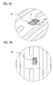
- FIG. 1 shows a perspective view of a vehicle tire 1, in which in the tread 2, a wear indicator in the form of a multi-layered QR® code 3 is introduced.
- the QR® code is designed as an iQR code, which is particularly suitable for cylindrical surfaces.
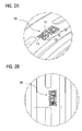
- FIG. 2A shows a perspective enlarged view of the section A of FIG. 1
- FIG. 2B shows an enlarged plan view of the section A of FIG. 1
- the FIGS. 2A and 2B in particular, show the uppermost level 3A of the QR® code when the tire is new.
- the information carriers of the QR® code d. H. the black dots and dashes 12 of the QR® code are formed by tire material. For reasons of simplified representability and better clarity, only some of the points or lines of the QR® code are identified by the reference numeral 12.
- the space between the information carriers 12 is designed in each case as a pocket.
- the current form of the QR® code describes the tire wear condition and other tire information in a digital manner and may be e.g. B. opto-electronically be read with a smartphone via the camera.
- the QR® code is multi-layered, such that with increasing wear, individual information carriers (dots or dashes 12) disappear. As the wear increases, so does the contour of the QR® code and thus its information content.
- FIGS. 3A and 3B exemplified, the section A of FIG. 1 show in a state that corresponds to a higher wear compared to the state of wear, in the FIGS. 2A and 2B is shown.
- the FIGS. 3A and 3B thus show a layer 3B of the QR® code, which is exposed by wear-induced ablation of the plane 3A.
- FIGS. 4A and 4B illustrate another condition with even greater wear, exposing the 3C level of the QR® code.
- the QR® code 3C the number of information carriers 12 is further reduced.
- the three-dimensional QR® code is designed so that the depth in the wear direction of the individual information carrier (lines and dots) is designed differently. While some information carriers pass through all levels of the QR® code and are thus visible in any state of wear, other information carriers may have a smaller depth and thus disappear with decreasing wear height of the consumable.
- a part of the information carrier is used for coding wear-state-independent indications, such as, for example, the manufacturer or the date of manufacture of the wearing part. These information carriers are maintained continuously and are visible in all exposed levels of the QR® code.
- the gap can be filled with a contrasting material which corresponds in its wear properties to the tire material and thus wears out just as quickly and does not cause a technical deterioration of the tire.
- this rubber can be used.
- this contrast mass can be made fluorescent, to ensure readability even in poor lighting conditions. This is especially necessary for tires that are not steerable and located in tight wheel arches.
- FIG. 5A and 5B illustrate schematically the introduction of the wear indicator and its multi-layered structure.
- the wear indicator can be inserted into a pocket 4, which is introduced in the tread of the tire. This has the particular advantage that the wear indicator can be retrofitted and / or manufactured separately.
- the wear indicator can thus be manufactured separately, for example by injection molding, and then filled with a refill material.
- the filling compound also has the advantage that no dirt can accumulate in the pockets between the information carriers.
- FIG. 5B illustrates the multi-layer structure of the wear indicator 3, wherein in the present example, for simplicity of illustration only three levels 3A, 3B and 3C of the QR® code are shown, which represent the wear-dependent appearance of the wear indicator or QR® code.
- FIG. 5B It is shown that the number of information carriers 12 in the upper levels is greater than in the lower levels.
- the wear feature can be carried out in particular one or more parts.
- a multi-part feature can be applied in layers or first assembled and then applied as a single part.
- several levels with QR® or barcodes, which are already executed in black and contrasting colors, are applied one after the other. Subsequently, the wearing part can be introduced into a pocket 4 provided in the tire casing 2.
- the three-level representation and three different implementations of the QR® code are merely exemplary and the three-dimensional QR® code or generally the three-dimensional pattern may also include a different number of different two-dimensional QR® codes or patterns.
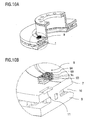
- FIGS. 6 to 10B illustrate a further application of the invention, in which the wear indicator according to the invention is used in a brake disc.
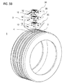
- FIG. 6 shows a sectional view of an internally ventilated brake disc 5 with two annular brake discs 7, 8.
- the wear indicator 9 is introduced into at least one of the friction surfaces 6.
- FIG. 7 shows an enlarged perspective view of the area A of FIG. 6 ,
- the friction surface 6 for example, by drilling or milling a three-dimensional structure is introduced, wherein the introduced depressions are the information carrier 12, 12a of a three-dimensional QR® code 9.
- the introduced depressions are the information carrier 12, 12a of a three-dimensional QR® code 9.
- a two-dimensional plane of the QR® code is visible in each case.
- FIG. 7 shows that the individual information carriers 12, 12a extend at different depths in the wear direction, ie perpendicular to the friction surface 6, so that the contour of the QR® code 9 changes depending on the wear state of the brake disk.
- FIG. 8 shows a state of higher wear compared to FIG. 7 , Consequently, in the state of wear of the FIG. 8 revealed another level 9B of the QR® code because the overlying level 9A was removed due to wear.
- the layer 9B of the QR® code of FIG. 8 shows less information carrier 12 than the plane 9A of FIG. 7 , Due to the changed contour of the exposed plane, the information content of the QR® code changes.
- the contour of the plane 9B is a state of higher wear than the contour of the plane 9A of FIG. 7 associated with what is correspondingly in the consumer mobile device, eg. B. smartphone, is deposited. If the smartphone detects the contour of the plane 9B by photographing the point A of the friction surface 6, the smartphone can determine the corresponding state of wear and display it to the user.
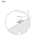
- FIG. 3 In the simplified example of FIG. 3 three depths t1, t2 and t3 of the information carriers 12, 12a are shown.
- the information carriers 12 with the depth t1 that disappear in the first place disappear FIG. 8 are no longer visible, and then the information carrier 12 with the depth t2, in the FIG. 9 are no longer visible.
- FIG. 9 Thus, only the information carrier 12a with the depth t3 are visible.
- the exposed plane 9C of the wear state of the FIG. 9 contains only the elements 12A of the QR® code that have the highest depth. Thus, if the brake disc is removed by wear so far that only the QR® code 9C is visible, it can be concluded that the brake disc has a very high wear and must be renewed.
- FIGS. 10A and 10B illustrate schematically the multilayer structure of the wear indicator 9 and the introduction of the wear indicator 9 in a pocket 11 which is introduced into the friction surface 6 of the brake disc.
- the levels 9A, 9B and 9C of the QR® codes represent the wear-dependent appearance of the wear indicator or the QR® code.
- brake discs recesses 11 such.
- B. pockets or holes may be provided, in which the wear indicator in Form of the multilayer QR® code 9 is subsequently fixed. This can be done by pressing, welding or screwing.
- the wear indicator itself can be produced in a separate process. By a layer construction of the wear indicator then also possible complex three-dimensional shapes for the representation of a QR® code can be implemented more easily. Alternatively, reshaping measures can be used to introduce the feature.
- QR® code also a bar code can be used.
- wear-sensitive information such codes can also be used to self-code brake disc information that does not change beyond wear, such as date of manufacture, axle, vehicle side, unique manufacturer identifier (ID), etc.
- QR® codes Another advantage of using QR® codes is the ability to encode data in redundant form so that measurement inaccuracies due to contamination or the like can be avoided over the multitude of points.
Abstract
Die Erfindung betrifft ein Verschleißteil (1), nämlich einen Reifen für ein Fahrzeug, umfassend einen Verschleißindikator, dessen Erscheinung sich in Abhängigkeit von einem Verschleißzustand des Verschleißteils ändert, wobei der Verschleißindikator ein mehrdimensionales Muster (3) umfasst, das so am Verschleißteil angeordnet ist, dass in Abhängigkeit von dem Verschleißzustand unterschiedliche Ebenen (3A, 3B, 3C) des Musters freigelegt sind.The invention relates to a wear part (1), namely a tire for a vehicle, comprising a wear indicator whose appearance changes in dependence on a wear state of the wearing part, the wear indicator comprising a multi-dimensional pattern (3) which is thus arranged on the wearing part, in that different planes (3A, 3B, 3C) of the pattern are exposed depending on the state of wear.
Description
Die Erfindung betrifft ein Verschleißteil, nämlich einen Reifen für ein Fahrzeug, mit einem Verschleißindikator, dessen Erscheinung sich in Abhängigkeit von einem Verschleißzustand des Verschleißteils ändert. Die Erfindung betrifft ferner ein System zur Verschleißprüfung.The invention relates to a wear part, namely a tire for a vehicle, with a wear indicator, the appearance of which changes in dependence on a wear state of the wearing part. The invention further relates to a system for wear testing.
Die Erfindung betrifft einen Reifen als Beispiel für das Verschleißteil, der mit dem erfindungsgemäßen Verschleißindikator ausgestattet ist. Aus der Praxis ist es bekannt, dass der Verschleißzustand eines Reifens regelmäßig geprüft werden muss, um die Funktionalität des Reifens zu überwachen und um gesetzliche Vorschriften zu erfüllen. Bei Nutzfahrzeugen können nach Erreichen der Verschleißgrenze Reifen bis zu zweimal nachgeschnitten und einmal runderneuert werden. Zur Abschätzung, wann ein Tausch bzw. eine Erneuerung der Reifen oder Profile notwendig ist, kommen Verschleißmerkmale und -prognosen zum Einsatz.The invention relates to a tire as an example of the wearing part, which is equipped with the wear indicator according to the invention. From practice it is known that the wear condition of a tire must be checked regularly to monitor the functionality of the tire and to meet legal requirements. For commercial vehicles, after the wear limit has been reached, tires can be re-cut up to twice and once retreaded. In order to estimate when replacement or renewal of tires or profiles is necessary, wear characteristics and forecasts are used.
Aus dem Stand der Technik sind beispielsweise Verfahren bekannt, die aus dem Fahrverhalten des Fahrers den Reifenverschleißzustand abschätzen. Aus der
Des Weiteren sind auch Verschleißmerkmale bekannt, die entweder akustisch (vgl.
Die bekannten Ansätze weisen eine Reihe von Nachteilen auf. Die vorstehend genannten Schätzverfahren, die aus dem Fahrverhalten einen Verschleiß errechnen, können nicht alle äußeren Umstände berücksichtigen und sind daher ungenau. Eine automatische Speicherung und Auswertung des Verschleißzustands kann nur mit integrierten Reifensensoren oder optischen Systemen erreicht werden. Sensoren, die in den Reifen eingearbeitet werden, haben jedoch den Nachteil, dass diese teuer sind und robust ausgeführt sein müssen, um eine Runderneuerung bzw. ein Nachschneiden zu ermöglichen.The known approaches have a number of disadvantages. The abovementioned estimation methods, which calculate wear from the driving behavior, can not take into account all external circumstances and are therefore inaccurate. Automatic storage and evaluation of the wear condition can only be achieved with integrated tire sensors or optical systems. Sensors that are incorporated in the tires have but the disadvantage that they are expensive and must be made robust to allow retreading or recutting.
Die vorstehend genannten Systeme, die ein optisches Merkmal sicher erfassen und auswerten können, bedürfen einer hohen Qualität und sind somit ebenfalls sehr kostenaufwändig. Eine Vertiefung oder Erhebung in einem Reifen ist zudem mit einfachen optischen Systemen nur schwer zu erfassen. Verschleißmerkale in Form von Taschen können sich zudem mit Schmutz, Schlamm oder anderen Verunreinigungen füllen und das Messen und Erkennen des Merkmals zusätzlich erschweren. Aufgrund der dunklen Farbe des Reifens ist selbst ohne Verschmutzung der Kontrast zwischen Lauffläche und Verschleißmerkmal zu gering, um ihn sicher erkennen zu können. Bei den aus dem Stand der Technik bekannten Verfahren können daher Messfehler nicht ausgeschlossen werden.The above-mentioned systems, which can reliably detect and evaluate an optical feature, require a high quality and are therefore also very expensive. An indentation in a tire is also difficult to detect with simple optical systems. Wear features in the form of pockets can also fill with dirt, mud or other impurities and make it even more difficult to measure and recognize the feature. Due to the dark color of the tire, even without soiling, the contrast between the tread and the wear feature is too low to be reliably detected. In the methods known from the prior art, therefore, measurement errors can not be excluded.
Es ist somit eine Aufgabe der Erfindung, einen Reifen umfassend einen verbesserten Verschleißindikator bereitzustellen, mit dem Nachteile herkömmlicher Techniken zur Verschleißprüfung vermieden werden können. Die Aufgabe der Erfindung ist es insbesondere, einen Verschleißindikator bereitzustellen, mit dem der Verschleißzustand zuverlässig erkannt und ausgewertet werden kann. Es ist eine weitere Aufgabe der Erfindung, ein System zur Verschleißprüfung bereitzustellen, das eine schnelle und sichere Erfassung und Überwachung des Verschleißzustandes des Reifens ermöglicht.It is thus an object of the invention to provide a tire comprising an improved wear indicator which avoids the disadvantages of conventional wear testing techniques. The object of the invention is in particular to provide a wear indicator with which the wear state can be reliably detected and evaluated. It is a further object of the invention to provide a system for wear testing that enables rapid and reliable detection and monitoring of the state of wear of the tire.
Diese Aufgaben werden durch einen Reifen mit einem Verschleißindikator gemäß den Merkmalen der unabhängigen Ansprüche gelöst. Vorteilhafte Ausführungsformen und Anwendungen der Erfindung sind Gegenstand der abhängigen Ansprüche und werden in der folgenden Beschreibung unter teilweiser Bezugnahme auf die Figuren näher erläutert.These objects are achieved by a tire with a wear indicator according to the features of the independent claims. Advantageous embodiments and applications of the invention are the subject matter of the dependent claims and are explained in more detail in the following description with partial reference to the figures.
Das erfindungsgemäße Verschleißteil, nämlich ein Reifen für ein Fahrzeug, weist in Übereinstimmung mit dem Stand der Technik einen Verschleißindikator auf, dessen Erscheinung sich in Abhängigkeit von einem Verschleißzustand des Verschleißteils ändert.The wear part according to the invention, namely a tire for a vehicle, in accordance with the prior art has a wear indicator, the appearance of which changes in dependence on a wear state of the wearing part.
Gemäß allgemeinen Gesichtspunkten der Erfindung umfasst der Verschleißindikator ein mehrdimensionales Muster, das so am Verschleißteil angeordnet ist, dass in Abhängigkeit von dem Verschleißzustand unterschiedliche Ebenen des Musters freigelegt sind.According to general aspects of the invention, the wear indicator comprises a multi-dimensional pattern arranged on the wearing part so that different levels of the pattern are exposed depending on the state of wear.
Ein mehrdimensionales Muster im Sinne dieser Erfindung umfasst eine Mehrzahl von in Verschleißrichtung übereinander angeordneten unterschiedlichen (Verschleiß-)Ebenen, die jeweils ein Muster aufweisen, das jeweils einem Verschleißzustand zugeordnet ist. Bei zunehmendem Verschleiß des Verschleißteils werden nacheinander verschiedene Ebenen des mehrdimensionalen Musters verschleißbedingt abgetragen, so dass in Abhängigkeit vom Verschleißzustand unterschiedliche Muster in einer zweidimensionalen Fläche sichtbar sein können. Die Anzahl in Verschleißrichtung übereinander angeordneter Muster ist dabei nicht auf eine bestimmte Zahl beschränkt. Je höher die Zahl derart übereinander angeordneter Muster, desto höher die Anzahl der bestimmbaren unterschiedlicher Verschleißzustände.A multi-dimensional pattern in the sense of this invention comprises a plurality of different (wear) planes arranged one above the other in the direction of wear, each having a pattern which is assigned in each case to a state of wear. With increasing Wear of the wear part are successively removed various levels of the multi-dimensional pattern due to wear, so that depending on the state of wear different patterns can be visible in a two-dimensional surface. The number of superimposed in the wear direction pattern is not limited to a specific number. The higher the number of such superposed patterns, the higher the number of identifiable different wear conditions.
Vorzugsweise ändert sich das mehrdimensionale Muster in Verschleißrichtung diskret, derart, dass in jedem Verschleißzustand eindeutig feststellbar ist, welches der übereinander angeordneten Muster freigelegt ist. Bei einer diskreten Änderung des Musters ändert sich zumindest ein Teil des Musters mit abnehmender Verschleißhöhe diskret, also nicht kontinuierlich. Anhand der diskreten Änderung kann zuverlässig der zu dem bestimmten freigelegten Muster zugeordnete Verschleißzustand bestimmt werden.Preferably, the multi-dimensional pattern changes discretely in the direction of wear, such that in each state of wear it can be clearly determined which of the superimposed patterns is uncovered. In a discrete change of the pattern, at least a part of the pattern changes discretely with decreasing wear height, ie not continuously. Based on the discrete change, the wear condition associated with the particular exposed pattern can be reliably determined.
Gemäß einem vorteilhaften Ausführungsbeispiel ist die jeweils freigelegte Ebene des Musters opto-elektronisch lesbar ausgeführt. Das Muster kann beispielsweise ein 2D-Code, vorzugsweise ein QR®-Code, oder 1 D-Code, vorzugsweise ein Strichcode sein, wie nachfolgend noch detaillierter beschrieben wird. Dies ermöglicht das schnelle Auslesen des Verschleißzustandes mit einem geeigneten optischen Lesegerät.According to an advantageous embodiment, the respectively exposed plane of the pattern is opto-electronically readable. The pattern may be, for example, a 2D code, preferably a QR® code, or 1D code, preferably a bar code, as will be described in more detail below. This allows the fast readout of the wear state with a suitable optical reader.
Die jeweils freigelegte Ebene des Musters kann Daten codieren, die indikativ für den jeweiligen Verschleißzustand sind. In den verschiedenen Ebenen des dreidimensionalen Musters können somit jeweils Daten betreffend den zugeordneten Verschleißzustand codiert sein, beispielsweise in binärer Form mittels eines QR®-Codes oder als Zeichen, codiert mittels eines Strichcodes. Dies ermöglicht ein digitales Auswerten und dadurch eine geringere Fehleranfälligkeit als bei analogen Auswerteverfahren. Ein weiterer Vorzug liegt darin, dass die Daten den Verschleißzustand genau beschreiben können, beispielsweise in Form einer Prozentangabe.The exposed plane of the pattern may encode data indicative of the particular wear condition. In the various levels of the three-dimensional pattern, data relating to the associated state of wear can thus be coded in each case, for example in binary form by means of a QR® code or as a character, coded by means of a barcode. This enables a digital evaluation and thus a lower susceptibility to errors than with analog evaluation methods. Another advantage is that the data can accurately describe the state of wear, for example in the form of a percentage.
Beispielsweise können die verschiedenen Ebenen des dreidimensionalen Musters einen eindimensionalen oder zweidimensionalen maschinenlesbaren Code umfassen.For example, the various levels of the three-dimensional pattern may include one-dimensional or two-dimensional machine-readable code.
Gemäß einem bevorzugten Ausführungsbeispiel stellen die verschiedenen Ebenen des mehrdimensionalen Musters jeweils einen 2D-Code, vorzugsweise einen QR®-Code, dar. Gemäß dieser Ausführungsvariante ist das dreidimensionale Muster somit als 2D-Code, z. B. als QR®-Code, ausgeführt, der seine Form bzw. sein Aussehen in Verschleißrichtung ändert, so dass sich der Informationsgehalt des 2D-Codes mit abnehmender Verschleißhöhe ändert. Der Verschleißindikator kann in der Ausführungsvariante mit QR®-Codes somit aus einer Mehrzahl übereinander angeordneter zweidimensionaler QR®-Codes bestehen. Der QR®-Code gemäß dieser Ausführungsvariante kann somit als dreidimensionaler QR®-Code bezeichnet werden.According to a preferred embodiment, the different levels of the multi-dimensional pattern each represent a 2D code, preferably a QR® code. According to this embodiment variant, the three-dimensional pattern is therefore a 2D code, e.g. B. as QR® code executed, which changes its shape or its appearance in the wear direction, so that the information content of the 2D code changes with decreasing wear level. The wear indicator can thus consist of a plurality of superimposed two-dimensional QR® codes in the embodiment variant with QR® codes. The QR® code according to this embodiment variant can thus be referred to as a three-dimensional QR® code.
Der Verschleißindikator mit dem dreidimensionalen QR®-Code wird so am Verschleißteil angeordnet, dass aufgrund des Verschleißes nacheinander die einzelnen Ebenen des QR®-Codes abgetragen werden und in Abhängigkeit vom Verschleißzustand immer jeweils ein zweidimensionaler QR®-Code sichtbar ist, der Informationen bzw. Daten betreffend den aktuellen Verschleißzustand binär codiert. Der QR®-Code kann ein Micro-QR®-Code oder ein iQR®-Code sein.The wear indicator with the three-dimensional QR® code is arranged on the wearing part in such a way that the individual levels of the QR® code are removed one after the other due to the wear and tear. Depending on the wear condition, a two-dimensional QR® code is always visible. Data regarding the current state of wear binary coded. The QR® code can be a Micro-QR® code or an iQR® code.
Bei einer weiteren Variante wird anstatt eines 2D-Codes bzw. QR®-Codes ein herkömmlicher 1 D-Code, z. B. ein Strichcode (engl. Barcode) verwendet, so dass die verschiedenen Ebenen des Musters jeweils einen Strichcode darstellen.In another variant, instead of a 2D code or QR® code, a conventional 1 D code, for. For example, a bar code is used so that the various levels of the pattern each represent a bar code.
Ein besonderer Vorteil der Verwendung der erfindungsgemäßen mehrdimensionalen 2D-Codes oder 1 D-Codes ist, dass der in einem Verschleißzustand jeweils freigelegte zweidimensionale 2D-Code oder 1D-Code opto-elektronisch auslesbar ist. Hierzu kann insbesondere ein herkömmliches Endverbraucher-Mobilgerät verwendet werden, beispielsweise ein Smartphone oder Tablet-Computer, die mittels einer entsprechenden Applikationssoftware zum Auslesen von 2D-Codes oder 1 D-Codes bzw. QR-Codes oder Strichcodes eingerichtet sind.A particular advantage of using the multi-dimensional 2D codes or 1 D codes according to the invention is that the two-dimensional 2D code or 1D code respectively exposed in a worn state can be opto-electronically read. For this purpose, in particular a conventional end user mobile device can be used, for example a smartphone or tablet computer, which are set up by means of a corresponding application software for reading 2D codes or 1 D codes or QR codes or bar codes.
Bei einer vorteilhaften Variante der vorgenannten Ausführungsformen kann sich eine Form des 2D-Codes und/oder des 1 D-Codes in Verschleißrichtung so ändern, dass eine Anzahl und/oder Form und/oder Lage und/oder Farbe von Informationsträgern abnimmt. Bei einem 2D-Code sind die Informationsträger die schwarzen Flächen und bei einem Strichcode die schwarzen Balken jeweils in Bezug zu den weißen Flächen bzw. weißen Balken. Dies ermöglicht eine besonders einfache Herstellung des dreidimensionalen 2D-Codes bzw. 1D-Codes.In an advantageous variant of the aforementioned embodiments, a shape of the 2D code and / or the 1 D code in the wear direction may change so that a number and / or shape and / or position and / or color of information carriers decreases. In a 2D code, the information carriers are the black areas, and in the case of a bar code, the black bars in relation to the white areas or white bars respectively. This allows a particularly simple production of the three-dimensional 2D code or 1D code.
Ferner kann das Muster so ausgebildet sein, dass zusätzlich andere, insbesondere verschleißzustandsunabhängige Eigenschaften des Verschleißteils codiert werden. Die verschleißzustandsunabhängigen Eigenschaften können beispielsweise eine Angabe betreffend den Hersteller, das Herstellungsdatums oder den Typ des Verschleißteils sein. Insbesondere bei Reifen können die verschleißzustandsunabhängigen Eigenschaften auch eine Angabe enthalten, ob und/oder wie oft der Reifen nachgeschnitten oder runderneuert wurde.Furthermore, the pattern may be formed so that in addition other, in particular wear state-independent properties of the wearing part are encoded. The wear state independent properties may include, for example, an indication the manufacturer, the date of manufacture or the type of wearing part. Especially in the case of tires, the wear-state independent properties may also include an indication of whether and / or how often the tire has been recut or retreaded.
Ein besonderer Vorzug des erfindungsgemäßen Verschleißindikators liegt somit darin, dass mittels des mehrdimensionalen Musters, beispielsweise des dreidimensionalen bzw. mehrschichtigen QR®-Codes, sowohl verschleißzustandsabhängige als auch verschleißzustandsunabhängige Daten codiert werden können, die eine verbesserte Analyse des Verschleißzustands ermöglichen.A particular advantage of the wear indicator according to the invention thus lies in the fact that both wear-state-dependent and wear-state-independent data can be coded by means of the multi-dimensional pattern, for example the three-dimensional or multi-layered QR® code, which enable an improved analysis of the wear state.
Bei einer vorteilhaften Variante dieser Ausgestaltungsform ist der Verschleißindikator so ausgebildet, dass die verschleißzustandsunabhängigen Eigenschaften des Verschleißteils in einem Bereich codiert sind, der sich in Verschleißrichtung nicht ändert. Gemäß dieser Ausführungsvariante kann somit die Anordnung derjenigen Informationsträger, beispielsweise des QR®-Codes oder des Strichcodes, die die verschleißzustandsunabhängigen Eigenschaften des Verschleißteils codieren, in jeder Ebene gleich sein.In an advantageous variant of this embodiment, the wear indicator is designed such that the wear-state-independent properties of the wearing part are encoded in a region which does not change in the direction of wear. According to this embodiment variant, the arrangement of those information carriers, for example of the QR® code or the bar code, which code the wear state-independent properties of the consumable part can thus be the same in every plane.
Vorstehend wurde bereits erwähnt, dass bei der Erfindung das Verschleißteil ein Reifen sein kann, bei dem der Verschleißindikator in die Lauffläche des Reifens eingebracht ist.It has already been mentioned above that in the invention the wearing part can be a tire in which the wear indicator is inserted in the running surface of the tire.
Ist das mehrdimensionale Muster bei dem Reifen als mehrschichtiger 2D-Code ausgeführt, können die schwarzen Flächen des 2D-Codes durch Reifenmaterial gebildet sein, und ein Zwischenraum zwischen den schwarzen Flächen des 2D-Codes kann als Tasche und/oder als Erhebung ausgeführt sein.If the multi-dimensional pattern in the tire is embodied as a multilayer 2D code, the black areas of the 2D code may be formed by tire material, and a space between the black areas of the 2D code may be embodied as a pocket and / or a protrusion.
In vergleichbarer Weise können bei der Ausführungsvariante mit einem mehrschichtigen 1 D-Code, z. B. Strichcode, die schwarzen Striche des 1 D-Codes durch Reifenmaterial gebildet sein, und ein Zwischenraum zwischen den schwarzen Strichen des 1 D-Codes kann als Tasche und/oder Erhebung ausgeführt sein.Similarly, in the embodiment with a multi-layer 1 D code, z. Bar code, the black bars of the 1-D code may be formed by tire material, and a space between the black bars of the 1-code may be embodied as a bag and / or a bump.
Mit anderen Worten werden die Informationsträger somit durch das Reifenmaterial dargestellt. Es wird betont, dass jedoch auch eine Inversion der vorgenannten Ausführungsvariante möglich ist, bei der der Zwischenraum der Informationsträger durch das Reifenmaterial gebildet ist.In other words, the information carriers are thus represented by the tire material. It is emphasized that, however, an inversion of the aforementioned embodiment variant is possible, in which the gap of the information carrier is formed by the tire material.
Ferner besteht im Rahmen der Erfindung die Möglichkeit, dass das Verschleißmerkmal als separat hergestelltes Bauteil hergestellt und nachträglich in eine vorhandene Tasche des Verschleißteils eingebracht ist.Furthermore, it is within the scope of the invention, the possibility that the wear feature is manufactured as a separately manufactured component and subsequently introduced into an existing pocket of the wearing part.
Um die Lesbarkeit des 2D-Codes bzw. allgemein des Musters zu erhöhen, ist es vorteilhaft, den Zwischenraum von den Informationsträgern mit einem Kontrastmittel zu versehen, beispielsweise durch Auffüllen mit einer Kontrastmasse, wobei eine Verschleißeigenschaft des Kontrastmittels bzw. der Kontrastmasse einer Verschleißeigenschaft des Reifenmaterials entspricht. Die Verschleißeigenschaft der Kontrastmasse kann der Verschleißeigenschaft des Reifenmaterials der Lauffläche entsprechen. Bei einer besonders einfachen Ausführungsvariante kann der Zwischenraum zwischen den Informationsträgern beispielsweise mit weißem Gummi aufgefüllt werden.In order to increase the readability of the 2D code or, more generally, of the pattern, it is advantageous to provide the intermediate space of the information carriers with a contrast agent, for example by filling with a contrast mass, wherein a wear property of the contrast agent or the contrast mass of a wear property of the tire material equivalent. The wear property of the contrasting mass may correspond to the wear characteristic of the tire material of the tread. In a particularly simple embodiment variant, the space between the information carriers can be filled with white rubber, for example.
Gemäß einer weiteren vorteilhaften Variante kann die Kontrastmasse fluoreszierend ausgeführt sein, um die Auslesbarkeit auch in schlechter Lichtumgebung zu gewährleisten. Dies ist besonders vorteilhaft bei Reifen, die nicht lenkbar sind und sich in engen Radkästen befinden.According to a further advantageous variant, the contrast mass can be designed to be fluorescent, in order to ensure the readability even in poor lighting conditions. This is particularly advantageous for tires that are not steerable and located in tight wheel arches.
Neben der vorstehend genannten beispielhaft hervorgehobenen Anwendung des erfindungsgemäßen Verschleißindikators bei einem Reifen umfasst eine weitere bevorzugte Anwendung der Erfindung die Anwendung des Verschleißindikators bei einer Bremsscheibe. Gemäß dieser Variante ist das Verschleißteil somit eine Bremsscheibe und der Verschleißindikator ist in einer Bremsfläche, auch Reibfläche genannt, der Bremsscheibe eingebracht.In addition to the abovementioned exemplary application of the wear indicator according to the invention in a tire, another preferred application of the invention comprises the application of the wear indicator in the case of a brake disk. According to this variant, the wearing part is thus a brake disc and the wear indicator is in a braking surface, also called friction surface, the brake disc introduced.
Beispielsweise kann das mehrdimensionale Muster durch eine Mehrzahl von nebeneinander angeordneten Taschen oder Erhebungen gebildet sein, die in die Reibfläche der Bremsscheibe eingebracht sind. Ein mehrdimensionales Muster bedeutet hier wiederum, dass sich das Muster über eine Fläche senkrecht zur Verschleißrichtung sowie in Verschleißrichtung erstreckt. Ferner kann sich in Abhängigkeit vom Verschleiß der Reibfläche die Zahl, Form und/oder Lage der in Draufsicht auf die Reibfläche sichtbaren Taschen oder Erhebungen diskret ändern.For example, the multi-dimensional pattern may be formed by a plurality of juxtaposed pockets or protrusions, which are introduced into the friction surface of the brake disc. Again, a multi-dimensional pattern means that the pattern extends over a surface perpendicular to the direction of wear and in the direction of wear. Furthermore, depending on the wear of the friction surface, the number, shape and / or position of the pockets or elevations visible in plan view of the friction surface may change discretely.
Somit ändert sich die Kontur des Verschleißindikators in Abhängigkeit vom Verschleißzustand, und der Verschleißzustand kann aus der in Draufsicht auf die Bremsscheibe sichtbaren Zahl, Form und/oder Lage der Taschen und/oder Erhebungen bestimmt werden. Gemäß einer weiteren Variante kann das Muster wiederum als mehrschichtiger QR®-Code oder mehrschichtiger Strichcode ausgebildet sein, der in die Bremsscheibe eingebracht ist. Der Begriff "mehrschichtig" bedeutet hier und in Zusammenhang mit den nachfolgenden Ausführungen, dass das Muster, z. B. der Code, mehrere in Verschleißrichtung übereinander angeordnete Ebenen aufweist, in denen das Muster unterschiedlich ausgeprägt ist. Der Begriff einer Schicht ist also in diesem Zusammenhang nicht zwangsläufig als eine stofflich abgeschlossene Materialeinheit zu verstehen.Thus, the contour of the wear indicator changes depending on the state of wear, and the state of wear can be determined from the visible in plan view of the brake disc number, shape and / or position of the pockets and / or elevations. According to another variant, the pattern may again be a multilayered QR® code or be formed multi-layered bar code, which is introduced into the brake disc. The term "multilayer" here and in connection with the following statements means that the pattern, z. As the code, a plurality of wear direction superposed planes has, in which the pattern is different pronounced. The concept of a layer is therefore not necessarily to be understood in this context as a material unit of material.
Ein weiterer Aspekt der Erfindung betrifft ein System zur Verschleißprüfung. Das System umfasst ein Verschleißteil mit einem Verschleißindikator nach einem der vorhergehenden Aspekte. Das System umfasst ferner ein multifunktionell nutzbares Endverbrauchermobilgerät, das mittels einer Applikationssoftware eingerichtet ist, ein jeweils sichtbares flächiges Muster des Verschleißindikators, beispielsweise einen sichtbaren 1 D-Code oder 2D-Code des Musters opto-elektronisch zu erfassen und auf Basis des erfassten dreidimensionalen Musters einen Verschleißzustand des Verschleißteils festzustellen.Another aspect of the invention relates to a system for wear testing. The system comprises a wear part with a wear indicator according to one of the preceding aspects. The system further comprises a multifunctionally usable end user mobile device, which is set up by means of an application software to opto-electronically detect a respective visible planar pattern of the wear indicator, for example a visible 1D code or 2D code of the pattern, and based on the detected three-dimensional pattern Determine the wear condition of the wearing part.
Das multifunktionell nutzbare Endverbrauchmobilgerät kann beispielsweise ein herkömmlicher handgehaltener Mobilcomputer, z. B. ein Smartphone oder ein Tablet-Computer, sein. In diesem Falle kann die Applikationssoftware eine sogenannte mobile App für das Smartphone oder den Tablet-Computer sein. Mit dem Endverbrauchermobilgerät kann der Verschleißindikator bei jeder Abfahrtskontrolle oder bei Bedarf vom Fahrer mit der Kamera des Geräts ausgelesen werden.The multifunctionally usable Endverbrauchmobilgerät, for example, a conventional hand-held mobile computer, z. As a smartphone or a tablet computer to be. In this case, the application software may be a so-called mobile app for the smartphone or the tablet computer. With the end user's mobile device, the wear indicator can be read by the driver with the camera of the device at each departure check or when needed.
Das Mobilgerät kann hierbei programmtechnisch so eingerichtet sein, dass zusätzlich zu den ausgelesenen verschleißzustandsabhängigen und verschleißzustandsunabhängigen Informationen, wie vorstehend beschrieben, auch Daten betreffend den aktuellen Ort und das Datum automatisch an eine zentrale Stelle, beispielsweise den Spediteur, gemeldet werden. In einem derartigen System kann ferner sichergestellt werden, dass vom Fahrer regelmäßig eine Abfahrtskontrolle durchgeführt wird. Ferner ist es möglich, über zeitlich gehäufte Auswertungen die Reststandzeit des Reifens zu ermitteln, um einen zukünftigen Reifenwechsel zu planen.The mobile device can be programmed in such a way that, in addition to the read-out wear-state-dependent and wear-state-independent information, as described above, data concerning the current location and the date are automatically reported to a central location, such as the forwarder. In such a system it can further be ensured that the driver regularly carries out a departure check. Furthermore, it is possible to use temporally accumulated evaluations to determine the remaining service life of the tire in order to plan a future tire change.
Ein besonderer Vorzug der Erfindung liegt somit darin, dass die gezeigten Verschleißindikatoren maschinenlesbar sind und insbesondere mittels eines herkömmlichen Smartphones, das mittels einer Applikationssoftware entsprechend eingerichtet ist, ausgelesen werden können. Die ausgelesenen Verschleißdaten können ferner über eine Telematik-Software an einen zentralen Rechner zur Ablage geschickt werden, wodurch der Fortschritt des Verschleißes dokumentiert und prognostiziert werden kann.A particular advantage of the invention thus lies in the fact that the wear indicators shown are machine-readable and, in particular, can be read out by means of a conventional smartphone, which is set up correspondingly by means of an application software. The readout wear data can also be transmitted via telematics software a central computer to the filing are sent, whereby the progress of the wear can be documented and predicted.
Ein weiterer Aspekt der Erfindung betrifft ein Fahrzeug, insbesondere ein Nutzfahrzeug, mit einem Verschleißteil nach einem der vorhergehenden Aspekte.Another aspect of the invention relates to a vehicle, in particular a commercial vehicle, with a wearing part according to one of the preceding aspects.
Weitere Einzelheiten und Vorteile der Erfindung werden im Folgenden unter Bezug auf die beigefügten Zeichnungen beschrieben. Es zeigen:
Figur 1- eine perspektivische Ansicht eines Reifens mit eingebrachtem QR®-Code als Verschleißindikator gemäß einem ersten Ausführungsbeispiel;
- Figur 2A und Figur 2B
- die Form des QR®-
Codes der Figur 1 in einem ersten Verschleißzustand; Figur 3A und Figur 3B- die Form des QR®-
Codes der Figur 1 in einem zweiten Verschleißzustand; - Figur 4A und Figur 4B
- die Form des QR®-
Codes der Figur 1 in einem dritten Verschleißzustand; - Figur 5A
- einen Reifen mit einer Tasche zur Einbringung des Verschleißindikators;
- Figur 5B
- schematisch den mehrschichtigen Aufbau des QR®-Codes;
Figur 6- eine Schnittansicht einer Bremsscheibe mit eingebrachtem QR®-Code als Verschleißindikator gemäß einem illustrativen Beispiel;
Figur 7- die Form des QR®-Codes in einem ersten Verschleißzustand;
Figur 8- die Form des QR®-Codes in einem zweiten Verschleißzustand;
Figur 9- die Form des QR®-Codes in einem dritten Verschleißzustand; und
- Figur 10A und Figur 10B
- schematisch den mehrschichtigen Aufbau und das Einbringen des QR®-Codes in die Reibfläche der Bremsscheibe.
- FIG. 1
- a perspective view of a tire with incorporated QR® code as a wear indicator according to a first embodiment;
- FIG. 2A and FIG. 2B
- the shape of the QR® code
FIG. 1 in a first state of wear; - Figure 3A and Figure 3B
- the shape of the QR® code
FIG. 1 in a second state of wear; - Figure 4A and Figure 4B
- the shape of the QR® code
FIG. 1 in a third state of wear; - FIG. 5A
- a tire having a pocket for incorporating the wear indicator;
- FIG. 5B
- schematically the multilayer structure of the QR® code;
- FIG. 6
- a sectional view of a brake disc with incorporated QR® code as a wear indicator according to an illustrative example;
- FIG. 7
- the shape of the QR® code in a first state of wear;
- FIG. 8
- the shape of the QR® code in a second state of wear;
- FIG. 9
- the shape of the QR® code in a third state of wear; and
- FIG. 10A and FIG. 10B
- schematically the multilayer structure and the introduction of the QR® code in the friction surface of the brake disc.
Die Informationsträger des QR®-Codes, d. h. die schwarzen Punkte und Striche 12 des QR®-Codes, sind durch Reifenmaterial gebildet. Aus Gründen der vereinfachten Darstellbarkeit und besseren Übersichtlichkeit sind nur einige der Punkte bzw. Striche des QR®-Codes mit dem Bezugszeichen 12 gekennzeichnet.The information carriers of the QR® code, d. H. the black dots and dashes 12 of the QR® code are formed by tire material. For reasons of simplified representability and better clarity, only some of the points or lines of the QR® code are identified by the
Der Zwischenraum zwischen den Informationsträgern 12 ist jeweils als Tasche ausgeführt. Die aktuelle Form des QR®-Codes beschreibt den Reifenverschleißzustand und weitere Informationen zum Reifen in digitaler Weise und kann z. B. mit einem Smartphone über dessen Kamera opto-elektronisch ausgelesen werden.The space between the
Der QR®-Code ist mehrschichtig ausgeführt, derart, dass mit zunehmendem Verschleiß einzelne Informationsträger (Punkte oder Striche 12) verschwinden. Mit zunehmendem Verschleiß ändert sich somit die Kontur des QR®-Codes und somit sein Informationsgehalt.The QR® code is multi-layered, such that with increasing wear, individual information carriers (dots or dashes 12) disappear. As the wear increases, so does the contour of the QR® code and thus its information content.
Dies ist in den
Im Vergleich zu den
Die
Hierbei ist der dreidimensionale QR®-Code so ausgeführt, dass die Tiefe in Verschleißrichtung der einzelnen Informationsträger (Striche und Punkte) unterschiedlich ausgeführt ist. Während einige Informationsträger durch alle Ebenen des QR®-Codes reichen und so in jedem Verschleißzustand sichtbar sind, können andere Informationsträger eine geringere Tiefe aufweisen und so mit abnehmender Verschleißhöhe des Verschleißteils verschwinden.Here, the three-dimensional QR® code is designed so that the depth in the wear direction of the individual information carrier (lines and dots) is designed differently. While some information carriers pass through all levels of the QR® code and are thus visible in any state of wear, other information carriers may have a smaller depth and thus disappear with decreasing wear height of the consumable.
In einer weiteren Ausführungsvariante (nicht dargestellt) wird ein Teil der Informationsträger zur Codierung von verschleißzustandsunabhängigen Angaben, wie beispielsweise den Hersteller oder das Herstellungsdatum des Verschleißteils, verwendet. Diese Informationsträger bleiben kontinuierlich erhalten und sind in allen freigelegten Ebenen des QR®-Codes sichtbar.In a further embodiment variant (not shown), a part of the information carrier is used for coding wear-state-independent indications, such as, for example, the manufacturer or the date of manufacture of the wearing part. These information carriers are maintained continuously and are visible in all exposed levels of the QR® code.
Vorstehend wurde bereits erwähnt, dass zur besseren Erkennbarkeit der schwarzen Punkte und Striche der Zwischenraum mit einer Kontrastmasse aufgefüllt werden kann, die in ihren Verschleißeigenschaften dem Reifenmaterial entspricht und somit genauso schnell verschleißt und keine technische Verschlechterung des Reifens verursacht. Beispielsweise kann hierfür Gummi verwendet werden. Grundsätzlich kann diese Kontrastmasse noch fluoreszierend ausgeführt sein, um die Lesbarkeit auch in schlechter Lichtumgebung zu gewährleisten. Dies ist gerade bei Reifen notwendig, die nicht lenkbar sind und sich in engen Radkästen befinden.It has already been mentioned above that in order to improve the visibility of the black dots and dashes, the gap can be filled with a contrasting material which corresponds in its wear properties to the tire material and thus wears out just as quickly and does not cause a technical deterioration of the tire. For example, this rubber can be used. Basically, this contrast mass can be made fluorescent, to ensure readability even in poor lighting conditions. This is especially necessary for tires that are not steerable and located in tight wheel arches.
Die
Der Verschleißindikator kann somit separat, beispielsweise durch Spritzguss, gefertigt werden und anschließend mit einer Nachfüllmasse aufgefüllt werden. Die Füllmasse hat ferner den Vorteil, dass sich kein Schmutz in den Taschen zwischen den Informationsträgern ansammeln kann.The wear indicator can thus be manufactured separately, for example by injection molding, and then filled with a refill material. The filling compound also has the advantage that no dirt can accumulate in the pockets between the information carriers.
In
Das Verschleißmerkmal kann insbesondere ein- oder auch mehrteilig ausgeführt sein. Ein mehrteiliges Merkmal kann schichtweise aufgebracht werden oder zuerst zusammengefügt und dann als Einzelteil aufgebracht werden. Bei einem mehrschichtigem Verschleißteil werden mehrere Ebenen mit QR®- oder Barcodes, die schon in Schwarz und Kontrastfarbe ausgeführt sind, nacheinander aufgebracht. Anschließend kann das Verschleißteil in eine vorgesehene Tasche 4 im Reifenmantel 2 eingebracht werden.The wear feature can be carried out in particular one or more parts. A multi-part feature can be applied in layers or first assembled and then applied as a single part. In a multi-layer wear part, several levels with QR® or barcodes, which are already executed in black and contrasting colors, are applied one after the other. Subsequently, the wearing part can be introduced into a
Es wird betont, dass die Darstellung mit drei Ebenen und drei unterschiedlichen Ausführungen des QR®-Codes nur beispielhaft ist und der dreidimensionale QR®-Code oder allgemein das dreidimensionale Muster auch eine andere Anzahl unterschiedlicher zweidimensionaler QR®-Codes oder Muster aufweisen kann.It is emphasized that the three-level representation and three different implementations of the QR® code are merely exemplary and the three-dimensional QR® code or generally the three-dimensional pattern may also include a different number of different two-dimensional QR® codes or patterns.
Die
Aus Gründen der vereinfachten Darstellbarkeit und besseren Übersichtlichkeit sind wiederum nur einige der Vertiefungen bzw. Informationsträger des QR®-Codes mit Bezugszeichen gekennzeichnet.For reasons of simplified representability and better clarity again only some of the depressions or information carrier of the QR® code are marked with reference numerals.
Die Schicht 9B des QR®-Codes der
In dem vereinfachten Beispiel der
Die freigelegte Ebene 9C des Verschleißzustands der
Die
In einer Ausführung der Erfindung können in Bremsscheiben definierte Ausnehmungen 11 wie z. B. Taschen oder Bohrungen vorgesehen sein, in welche der Verschleißindikator in Form des mehrschichtigen QR®-Codes 9 nachträglich fixiert wird. Dies kann durch Einpressen, Aufschweißen oder Einschrauben erfolgen.In one embodiment of the invention defined in brake discs recesses 11 such. B. pockets or holes may be provided, in which the wear indicator in Form of the multilayer
Der Verschleißindikator selbst kann in einem eigenen Verfahren hergestellt werden. Durch eine Schichtbauweise des Verschleißindikators können dann auch mögliche komplexe dreidimensionale Formen zur Darstellung eines QR®-Codes leichter umgesetzt werden. Alternativ können auch umformende Maßnahmen zum Einbringen des Merkmals verwendet werden.The wear indicator itself can be produced in a separate process. By a layer construction of the wear indicator then also possible complex three-dimensional shapes for the representation of a QR® code can be implemented more easily. Alternatively, reshaping measures can be used to introduce the feature.
Ferner ist anzumerken, dass neben dem QR®-Code ferner auch ein Strichcode verwendet werden kann. Neben den verschleißabhängigen Informationen können derartige Codes auch verwendet werden, um Informationen zur Bremsscheibe selbst zu codieren, die sich über den Verschleiß hinweg nicht ändern, beispielsweise Herstellungsdatum, Achse, Fahrzeugseite, eindeutige Herstellerkennung (ID), etc..It should also be noted that in addition to the QR® code also a bar code can be used. In addition to the wear-sensitive information, such codes can also be used to self-code brake disc information that does not change beyond wear, such as date of manufacture, axle, vehicle side, unique manufacturer identifier (ID), etc.
Ein weiterer Vorteil der Verwendung von QR®-Codes ist die Möglichkeit, Daten in redundanter Form zu codieren, so dass über die Vielzahl der Punkte somit auch Messungenauigkeiten durch Verunreinigen oder ähnliches vermieden werden können.Another advantage of using QR® codes is the ability to encode data in redundant form so that measurement inaccuracies due to contamination or the like can be avoided over the multitude of points.
Obwohl die Erfindung unter Bezugnahme auf bestimmte Ausführungsbeispiele beschrieben worden ist, ist eine Vielzahl von Varianten und Abwandlungen möglich, die ebenfalls von dem Erfindungsgedanken Gebrauch machen und deshalb in den Schutzbereich fallen. Folglich soll die Erfindung nicht auf die offenbarten bestimmten Ausführungsbeispiele begrenzt sein, sondern die Erfindung soll alle Ausführungsbeispiele umfassen, die in den Bereich der beigefügten Patentansprüche fallen.Although the invention has been described with reference to specific embodiments, a variety of variations and modifications are possible, which also make use of the spirit and therefore fall within the scope. Accordingly, the invention should not be limited to the particular embodiments disclosed, but the invention is intended to embrace all embodiments which fall within the scope of the appended claims.
- 11
- Reifentires
- 22
- Laufflächentreads
- 33
- Verschleißindikator, QR®-CodeWear indicator, QR® code
- 3A, 3B, 3C3A, 3B, 3C
- Verschleißabhängige Ebenen des Verschleißindikators bzw. QR®-CodesWear-dependent levels of the wear indicator or QR® code
- 44
- Einstecktascheinsertion pocket
- 55
- Bremsscheibebrake disc
- 66
- Reibflächefriction surface
- 7, 87, 8
- Bremsscheibenringebrake discs rings
- 99
- Verschleißindikator, QR®-CodeWear indicator, QR® code
- 9A, 9B, 9C9A, 9B, 9C
- verschleißabhängige Ebenen des Verschleißindikators bzw. QR®-CodesWear-dependent levels of the wear indicator or QR® code
- 1010
- Zwischenraum zur InnenbelüftungSpace for internal ventilation
- 1111
- Einstecktascheinsertion pocket
- 12, 12A12, 12A
- Informationsträgerinformation carrier
- t1, t2, t3t1, t2, t3
- Tiefe der InformationsträgerDepth of the information carrier
Claims (14)
dass der Verschleißindikator ein mehrdimensionales Muster (3; 9) umfasst, das so am Verschleißteil angeordnet ist, dass in Abhängigkeit von dem Verschleißzustand unterschiedliche Ebenen (3A, 3B, 3C) des Musters freigelegt sind.Tire (1), preferably for a vehicle, comprising a wear indicator whose appearance changes in dependence on a wear condition of the wearing part, characterized
in that the wear indicator comprises a multi-dimensional pattern (3; 9) arranged on the wearing part such that different planes (3A, 3B, 3C) of the pattern are exposed depending on the state of wear.
einen Reifen (1) nach einem der vorhergehenden Ansprüche; und
ein multi-funktionell nutzbares Endverbraucher-Mobilgerät, wobei das Mobilgerät mittels einer Applikationssoftware eingerichtet ist, einen sichtbaren 1 D-Code oder 2D-Code (3A, 3B, 3C;) des Verschleißindikators (3; 9) opto-elektronisch zu erfassen und auf Basis des erfassten 1 D-Codes oder 2D-Codes (3A, 3B, 3C;) einen Verschleißzustand und/oder weitere Eigenschaften des Verschleißteils (3; 9) festzustellenSystem for wear testing, comprising
a tire (1) according to any one of the preceding claims; and
a multi-functionally usable consumer mobile device, wherein the mobile device is set up by means of an application software to optoelectronically record a visible 1D code or 2D code (3A, 3B, 3C;) of the wear indicator (3; Based on the detected 1 D code or 2D codes (3A, 3B, 3C;) to determine a state of wear and / or other properties of the wearing part (3; 9)
Applications Claiming Priority (2)
| Application Number | Priority Date | Filing Date | Title |
|---|---|---|---|
| DE102014003985.4A DE102014003985A1 (en) | 2014-03-19 | 2014-03-19 | Wear part with a wear indicator and system for wear testing |
| EP15000120.4A EP2921322B1 (en) | 2014-03-19 | 2015-01-17 | Brake disc with a wear indicator and system for wear testing |
Related Parent Applications (2)
| Application Number | Title | Priority Date | Filing Date |
|---|---|---|---|
| EP15000120.4A Division EP2921322B1 (en) | 2014-03-19 | 2015-01-17 | Brake disc with a wear indicator and system for wear testing |
| EP15000120.4A Division-Into EP2921322B1 (en) | 2014-03-19 | 2015-01-17 | Brake disc with a wear indicator and system for wear testing |
Publications (2)
| Publication Number | Publication Date |
|---|---|
| EP3124292A1 true EP3124292A1 (en) | 2017-02-01 |
| EP3124292B1 EP3124292B1 (en) | 2018-12-26 |
Family
ID=52394079
Family Applications (2)
| Application Number | Title | Priority Date | Filing Date |
|---|---|---|---|
| EP15000120.4A Active EP2921322B1 (en) | 2014-03-19 | 2015-01-17 | Brake disc with a wear indicator and system for wear testing |
| EP16001973.3A Active EP3124292B1 (en) | 2014-03-19 | 2015-01-17 | Tyre with a wear indicator and system for wear testing |
Family Applications Before (1)
| Application Number | Title | Priority Date | Filing Date |
|---|---|---|---|
| EP15000120.4A Active EP2921322B1 (en) | 2014-03-19 | 2015-01-17 | Brake disc with a wear indicator and system for wear testing |
Country Status (6)
| Country | Link |
|---|---|
| US (1) | US9355346B2 (en) |
| EP (2) | EP2921322B1 (en) |
| CN (1) | CN104924857B (en) |
| BR (1) | BR102015001978B1 (en) |
| DE (1) | DE102014003985A1 (en) |
| RU (1) | RU2688118C2 (en) |
Families Citing this family (32)
| Publication number | Priority date | Publication date | Assignee | Title |
|---|---|---|---|---|
| US10544732B2 (en) * | 2011-07-28 | 2020-01-28 | Pratt & Whitney Canada Corp. | Rotary internal combustion engine with removable subchamber insert |
| AU2014262221C1 (en) | 2013-11-25 | 2021-06-10 | Esco Group Llc | Wear part monitoring |
| USD779402S1 (en) * | 2014-10-17 | 2017-02-21 | Shandong Haoxin Machinery Co., Ltd. | Brake drum |
| AU2016219005B2 (en) | 2015-02-13 | 2020-07-02 | Esco Group Llc | Monitoring ground-engaging products for earth working equipment |
| USD784221S1 (en) * | 2015-03-24 | 2017-04-18 | Shandong Haoxin Machinery Co., Ltd. | Brake drum |
| USD777626S1 (en) * | 2015-06-19 | 2017-01-31 | Shandong Haoxin Machinery Co., Ltd. | Brake drum |
| USD784220S1 (en) * | 2015-08-17 | 2017-04-18 | Shandong Haoxin Machinery Co., Ltd. | Brake drum |
| WO2017131702A1 (en) | 2016-01-28 | 2017-08-03 | Hewlett-Packard Development Company, L.P. | Data representing a wear indicator |
| EP3225428B1 (en) * | 2016-04-01 | 2020-05-27 | Nokian Renkaat Oyj | A mould for making a wear indicator into a pneumatic tyre and a pneumatic tyre comprising a wear indicator |
| FR3060821A1 (en) * | 2016-12-20 | 2018-06-22 | Compagnie Generale Des Etablissements Michelin | METHOD FOR DETERMINING THE WEAR CONDITION OF A TIRE FOR AIRCRAFT |
| FR3060457A1 (en) | 2016-12-20 | 2018-06-22 | Compagnie Generale Des Etablissements Michelin | TIRE TREAD WEAR INDICATOR FOR AIRCRAFT |
| USD823784S1 (en) * | 2017-01-24 | 2018-07-24 | The Goodyear Tire & Rubber Company | Tire tread wear indicator |
| CN106827972B (en) * | 2017-02-13 | 2017-12-05 | 湖北脉辉科技有限公司 | A kind of method of dynamic regulation Electricmotor car wheel wheel footpath |
| FR3063786A1 (en) * | 2017-03-08 | 2018-09-14 | Peugeot Citroen Automobiles Sa | BRAKE DEVICE DETECTING THE WEAR LEVEL OF A BRAKE DISC |
| DE102017204417A1 (en) * | 2017-03-16 | 2018-09-20 | Zf Friedrichshafen Ag | Reibbelaglamelle for a multi-plate clutch or a multi-disc brake of a motor vehicle |
| US10903969B2 (en) * | 2017-03-23 | 2021-01-26 | Apple Inc. | Modular control channel formats for uplink control information in a cellular communication system |
| US10762407B2 (en) * | 2017-04-05 | 2020-09-01 | General Electric Company | Component incorporating 3-D identification code |
| DE102017218675A1 (en) * | 2017-04-27 | 2018-10-31 | Robert Bosch Gmbh | Combined detection of wear of components of a brake system, in particular of a motor vehicle |
| DE102017222283A1 (en) * | 2017-12-08 | 2019-06-13 | Continental Reifen Deutschland Gmbh | Pneumatic vehicle tire having an opto-electronically readable code |
| DE102018202062A1 (en) * | 2018-02-09 | 2019-08-14 | Continental Reifen Deutschland Gmbh | Vehicle tires comprising a tread with vulcanette and manufacturing process |
| DE202018101197U1 (en) * | 2018-03-02 | 2019-06-06 | Kalenborn International Gmbh & Co. Kg | Wear protection element and lining |
| DE202018102000U1 (en) * | 2018-04-12 | 2019-06-27 | Igus Gmbh | Marking on injection molded parts for energy guiding chains |
| IT201800020395A1 (en) * | 2018-12-20 | 2020-06-20 | Pirelli | Method of controlling a molding and vulcanization process of a tire and tire obtained through a manufacturing process that implements this method |
| DE202019106916U1 (en) * | 2019-12-12 | 2021-03-15 | C. & E. Fein Gmbh | Magnetic base |
| US11465453B2 (en) | 2020-02-21 | 2022-10-11 | Moj.Io, Inc. | Computer system with tire wear measurement mechanism and method of operation thereof |
| DE102020203515A1 (en) | 2020-03-19 | 2021-09-23 | Zf Friedrichshafen Ag | Condition monitoring of replacement parts of a vehicle |
| EP3971440B1 (en) * | 2020-09-21 | 2023-12-27 | Brembo S.p.A. | Braking band of a disc brake disc and disc brake disc |
| US11413907B2 (en) | 2020-10-16 | 2022-08-16 | The Goodyear Tire & Rubber Company | Tire with shallow groove-based tread wear indicator |
| FR3116873A1 (en) * | 2020-11-30 | 2022-06-03 | Psa Automobiles Sa | BRAKE DISC BEARING AN INSCRIPTION ON AT LEAST ONE BRAKING TRACK |
| DE102021209133A1 (en) | 2021-08-19 | 2023-02-23 | Robert Bosch Gesellschaft mit beschränkter Haftung | Method and device for determining a wear condition of a tire |
| DE102022202788A1 (en) | 2022-03-22 | 2023-09-28 | Psa Automobiles Sa | Coated brake disc for a vehicle and method for producing such a coated brake disc for a vehicle |
| DE102022121420A1 (en) | 2022-08-01 | 2024-02-01 | Rühlicke GmbH | Wear ring and locking hook for a fifth wheel lock of a fifth wheel coupling of a tractor unit of a semi-trailer vehicle |
Citations (16)
| Publication number | Priority date | Publication date | Assignee | Title |
|---|---|---|---|---|
| US2102784A (en) | 1936-02-06 | 1937-12-21 | Socony Vacuum Oil Co Inc | Method of making a wear indicating tire |
| DE1803483A1 (en) | 1967-10-18 | 1969-05-14 | Dunlop Co Ltd | Vehicle tires |
| DE2457334C3 (en) | 1973-12-05 | 1980-10-09 | Kennametal Inc., Latrobe, Pa. (V.St.A.) | Vehicle tires with wear indicator |
| DE3627833A1 (en) | 1986-08-16 | 1988-02-18 | Continental Gummi Werke Ag | Pneumatic vehicle tyre having a wear indicator |
| US6220199B1 (en) | 1999-01-21 | 2001-04-24 | Wildon Williams | Tire with worn tread indicator |
| US6289958B1 (en) | 1998-10-19 | 2001-09-18 | The Goodyear Tire & Rubber Company | Tire with tread containing electrically conductive stitched thread |
| US20020036039A1 (en) * | 2000-08-10 | 2002-03-28 | The Yokohama Rubber Co., Ltd. | Pneumatic tire and measuring method of tread wear amount of the same |
| US7050017B2 (en) | 2002-08-14 | 2006-05-23 | King Patrick F | RFID tire belt antenna system and method |
| EP1798071A2 (en) | 2005-12-15 | 2007-06-20 | Societe de Technologie Michelin | Tyre with wear sensor |
| WO2007102790A2 (en) * | 2006-03-08 | 2007-09-13 | Continental Matador Rubber, S.R.O. | Motor-vehicle tyre provided with a tread pattern wear indicator |
| JP2009107484A (en) * | 2007-10-30 | 2009-05-21 | Hitachi Software Eng Co Ltd | Tire information provision system |
| WO2010012735A1 (en) | 2008-07-31 | 2010-02-04 | Societe De Technologie Michelin | Tyre wear indicator |
| EP1705034B9 (en) | 2005-03-25 | 2010-07-21 | Société de Technologie Michelin | Wear indicator for tyres |
| US20120010776A1 (en) | 2009-03-19 | 2012-01-12 | Michelin Recherche Et Technique S.A. | Method for monitoring the condition of a tyre. |
| US20120266649A1 (en) | 2009-12-02 | 2012-10-25 | Michelin Recherche Et Technique S.A. | Method for detecting wear of a tyre |
| DE102011050911A1 (en) * | 2011-06-08 | 2012-12-13 | Continental Reifen Deutschland Gmbh | Vehicle tires |
Family Cites Families (18)
| Publication number | Priority date | Publication date | Assignee | Title |
|---|---|---|---|---|
| USH1283H (en) * | 1989-07-11 | 1994-02-01 | Andrew Porto | Wear-indicating tire |
| DE4002695A1 (en) * | 1990-01-27 | 1991-08-01 | Porsche Ag | Car brake disc with two-side friction faces - which have raised regions between marks in disc rotation direction |
| EP0985841B1 (en) * | 1998-09-11 | 2003-02-26 | Brembo S.p.A. | High efficiency brake disc with grooves for water draining and for visual wear control |
| DE19928747A1 (en) * | 1999-06-23 | 2000-12-28 | Continental Teves Ag & Co Ohg | Brake disc for a disc brake |
| FI112340B (en) | 1999-06-29 | 2003-11-28 | Nokian Renkaat Oyj | Vehicle tire tread with means for indicating at any instant the depth of the tread grooves |
| DE19939199B4 (en) | 1999-08-18 | 2005-12-15 | Sachtleben Chemie Gmbh | Use of polymer-based paints |
| JP2005216077A (en) * | 2004-01-30 | 2005-08-11 | Bridgestone Corp | Bar code label with built-in rfid, tire and management method therefor |
| US20060037683A1 (en) | 2004-08-23 | 2006-02-23 | Andre Cuny | Tire tread wear indicator and molding device for forming a tread wear indicator |
| US7367496B2 (en) * | 2005-06-06 | 2008-05-06 | International Business Machines Corporation | Detecting wear through use of information-transmitting devices |
| US7604029B2 (en) | 2005-12-15 | 2009-10-20 | Michelin Recherche Et Technique S.A. | Wear indicating tire |
| FR2895305B1 (en) * | 2005-12-27 | 2009-04-17 | Goss Int Montataire Sa | PRINTING PRESS WITH ENHANCED BAND COMMITMENT AND METHOD OF ENGAGING CORRESPONDING BAND. |
| EP1894747A3 (en) * | 2006-08-30 | 2009-07-01 | Toyo Tire Rubber Co., Ltd. | Pneumatic tire provided with temperature-sensitive color-changing part |
| US7877216B2 (en) * | 2008-07-30 | 2011-01-25 | Honeywell International Inc. | Method, system, and apparatus for friction pad wear and brake condition monitoring |
| US8585843B2 (en) * | 2010-03-08 | 2013-11-19 | Bridgestone Bandag, Llc | Tire tread buffing apparatus and method |
| JP5569203B2 (en) * | 2010-07-13 | 2014-08-13 | 横浜ゴム株式会社 | Tire information monitoring system and method for setting tire information monitoring system |
| DE102010037382A1 (en) * | 2010-09-07 | 2012-03-08 | Jürgen Wörner | Brake disc and device for checking the residual thickness of a brake disc |
| US8403012B2 (en) | 2010-11-23 | 2013-03-26 | The Goodyear Tire & Rubber Company, Inc. | Tread wear indicator |
| US20140319209A1 (en) * | 2012-10-09 | 2014-10-30 | Robert Dale Beadles | Memory tag hybrid multidimensional bar-text code with rewards and incentives |
-
2014
- 2014-03-19 DE DE102014003985.4A patent/DE102014003985A1/en not_active Withdrawn
-
2015
- 2015-01-17 EP EP15000120.4A patent/EP2921322B1/en active Active
- 2015-01-17 EP EP16001973.3A patent/EP3124292B1/en active Active
- 2015-01-28 BR BR102015001978-5A patent/BR102015001978B1/en active IP Right Grant
- 2015-03-13 RU RU2015108927A patent/RU2688118C2/en active
- 2015-03-19 CN CN201510120446.2A patent/CN104924857B/en active Active
- 2015-03-19 US US14/662,472 patent/US9355346B2/en active Active
Patent Citations (17)
| Publication number | Priority date | Publication date | Assignee | Title |
|---|---|---|---|---|
| US2102784A (en) | 1936-02-06 | 1937-12-21 | Socony Vacuum Oil Co Inc | Method of making a wear indicating tire |
| DE1803483A1 (en) | 1967-10-18 | 1969-05-14 | Dunlop Co Ltd | Vehicle tires |
| DE2457334C3 (en) | 1973-12-05 | 1980-10-09 | Kennametal Inc., Latrobe, Pa. (V.St.A.) | Vehicle tires with wear indicator |
| DE3627833A1 (en) | 1986-08-16 | 1988-02-18 | Continental Gummi Werke Ag | Pneumatic vehicle tyre having a wear indicator |
| US6289958B1 (en) | 1998-10-19 | 2001-09-18 | The Goodyear Tire & Rubber Company | Tire with tread containing electrically conductive stitched thread |
| US6220199B1 (en) | 1999-01-21 | 2001-04-24 | Wildon Williams | Tire with worn tread indicator |
| US20020036039A1 (en) * | 2000-08-10 | 2002-03-28 | The Yokohama Rubber Co., Ltd. | Pneumatic tire and measuring method of tread wear amount of the same |
| US7050017B2 (en) | 2002-08-14 | 2006-05-23 | King Patrick F | RFID tire belt antenna system and method |
| EP1705034B9 (en) | 2005-03-25 | 2010-07-21 | Société de Technologie Michelin | Wear indicator for tyres |
| EP1798071A2 (en) | 2005-12-15 | 2007-06-20 | Societe de Technologie Michelin | Tyre with wear sensor |
| WO2007102790A2 (en) * | 2006-03-08 | 2007-09-13 | Continental Matador Rubber, S.R.O. | Motor-vehicle tyre provided with a tread pattern wear indicator |
| US8162014B2 (en) | 2006-03-08 | 2012-04-24 | Continental Matador Rubber, S.R.O. | Motor-vehicle tyre provided with a tread pattern wear indicator |
| JP2009107484A (en) * | 2007-10-30 | 2009-05-21 | Hitachi Software Eng Co Ltd | Tire information provision system |
| WO2010012735A1 (en) | 2008-07-31 | 2010-02-04 | Societe De Technologie Michelin | Tyre wear indicator |
| US20120010776A1 (en) | 2009-03-19 | 2012-01-12 | Michelin Recherche Et Technique S.A. | Method for monitoring the condition of a tyre. |
| US20120266649A1 (en) | 2009-12-02 | 2012-10-25 | Michelin Recherche Et Technique S.A. | Method for detecting wear of a tyre |
| DE102011050911A1 (en) * | 2011-06-08 | 2012-12-13 | Continental Reifen Deutschland Gmbh | Vehicle tires |
Also Published As
| Publication number | Publication date |
|---|---|
| BR102015001978A2 (en) | 2016-05-31 |
| CN104924857A (en) | 2015-09-23 |
| RU2688118C2 (en) | 2019-05-17 |
| DE102014003985A1 (en) | 2015-09-24 |
| EP3124292B1 (en) | 2018-12-26 |
| EP2921322B1 (en) | 2018-03-28 |
| EP2921322A2 (en) | 2015-09-23 |
| RU2015108927A3 (en) | 2018-10-19 |
| US9355346B2 (en) | 2016-05-31 |
| EP2921322A3 (en) | 2015-11-18 |
| US20150269468A1 (en) | 2015-09-24 |
| CN104924857B (en) | 2018-12-04 |
| BR102015001978B1 (en) | 2020-12-01 |
| RU2015108927A (en) | 2016-10-10 |
| RU2019112252A (en) | 2019-05-06 |
Similar Documents
| Publication | Publication Date | Title |
|---|---|---|
| EP3124292B1 (en) | Tyre with a wear indicator and system for wear testing | |
| EP2993541B1 (en) | Process for the evaluation of the quality of a component which is realized by an additive manufacturing process | |
| DE69629083T2 (en) | Method for predicting and checking the tread wear of a pneumatic tire and the associated pneumatic tire | |
| WO2013149824A1 (en) | Method and device for tyre pressure testing | |
| DE112017002914T5 (en) | Brake rotor with optical wear indicator | |
| EP3482975A1 (en) | Tracked vehicle | |
| DE202014104780U1 (en) | Driverless floorbound vehicle | |
| DE60314423T2 (en) | Automatic wear warning system for tires and corresponding tires for this system | |
| DE102008021497A1 (en) | Pneumatic vehicle tire with a profile design with abrasion indicator | |
| CH692242A5 (en) | Wear plates for equipment and / or machinery of scrap, bulky waste or Abfallaufbereitungl. | |
| DE102010037382A1 (en) | Brake disc and device for checking the residual thickness of a brake disc | |
| DE19841096C1 (en) | Disc brake for motor vehicle | |
| EP1314580A1 (en) | Process for the determination of the tread depth of a tire and tire | |
| EP2703823B1 (en) | Wheel detection | |
| DE102011050911A1 (en) | Vehicle tires | |
| DE102014112402B4 (en) | Brake system of a commercial vehicle | |
| DE3701348C2 (en) | ||
| DE102016221267A1 (en) | Solid rubber tires and method for producing a solid rubber tire | |
| RU2785932C2 (en) | Tire with wear indicator and wear testing system | |
| DE102018200201A1 (en) | Method for producing a vehicle tire | |
| EP3587336A1 (en) | Sliding element with wear level detection | |
| DE102018202604A1 (en) | Tires, in particular vehicle tires, with a sensor arrangement, and methods for determining a tread depth of the tire | |
| DE102022205924A1 (en) | Method for evaluating the tread condition of vehicle tires | |
| DE102010035643A1 (en) | Device for determining e.g. wear of ceramic brake disk of motor vehicle, has indicators whose image is received by camera, and image processing unit determining abrasion and/or wear of disk based on brightness distribution in image | |
| DE102021004255A1 (en) | Tire profile height test piece using color scale |
Legal Events
| Date | Code | Title | Description |
|---|---|---|---|
| PUAI | Public reference made under article 153(3) epc to a published international application that has entered the european phase |
Free format text: ORIGINAL CODE: 0009012 |
|
| STAA | Information on the status of an ep patent application or granted ep patent |
Free format text: STATUS: THE APPLICATION HAS BEEN PUBLISHED |
|
| AC | Divisional application: reference to earlier application |
Ref document number: 2921322 Country of ref document: EP Kind code of ref document: P |
|
| AK | Designated contracting states |
Kind code of ref document: A1 Designated state(s): AL AT BE BG CH CY CZ DE DK EE ES FI FR GB GR HR HU IE IS IT LI LT LU LV MC MK MT NL NO PL PT RO RS SE SI SK SM TR |
|
| STAA | Information on the status of an ep patent application or granted ep patent |
Free format text: STATUS: REQUEST FOR EXAMINATION WAS MADE |
|
| 17P | Request for examination filed |
Effective date: 20170728 |
|
| RBV | Designated contracting states (corrected) |
Designated state(s): AL AT BE BG CH CY CZ DE DK EE ES FI FR GB GR HR HU IE IS IT LI LT LU LV MC MK MT NL NO PL PT RO RS SE SI SK SM TR |
|
| RIC1 | Information provided on ipc code assigned before grant |
Ipc: B60C 11/24 20060101AFI20180626BHEP Ipc: G06K 19/06 20060101ALI20180626BHEP Ipc: F16D 65/12 20060101ALI20180626BHEP Ipc: F16D 66/02 20060101ALI20180626BHEP Ipc: F16D 65/02 20060101ALI20180626BHEP |
|
| GRAP | Despatch of communication of intention to grant a patent |
Free format text: ORIGINAL CODE: EPIDOSNIGR1 |
|
| STAA | Information on the status of an ep patent application or granted ep patent |
Free format text: STATUS: GRANT OF PATENT IS INTENDED |
|
| INTG | Intention to grant announced |
Effective date: 20180809 |
|
| GRAS | Grant fee paid |
Free format text: ORIGINAL CODE: EPIDOSNIGR3 |
|
| GRAA | (expected) grant |
Free format text: ORIGINAL CODE: 0009210 |
|
| STAA | Information on the status of an ep patent application or granted ep patent |
Free format text: STATUS: THE PATENT HAS BEEN GRANTED |
|
| AC | Divisional application: reference to earlier application |
Ref document number: 2921322 Country of ref document: EP Kind code of ref document: P |
|
| AK | Designated contracting states |
Kind code of ref document: B1 Designated state(s): AL AT BE BG CH CY CZ DE DK EE ES FI FR GB GR HR HU IE IS IT LI LT LU LV MC MK MT NL NO PL PT RO RS SE SI SK SM TR |
|
| REG | Reference to a national code |
Ref country code: GB Ref legal event code: FG4D Free format text: NOT ENGLISH |
|
| REG | Reference to a national code |
Ref country code: CH Ref legal event code: EP |
|
| REG | Reference to a national code |
Ref country code: AT Ref legal event code: REF Ref document number: 1080894 Country of ref document: AT Kind code of ref document: T Effective date: 20190115 |
|
| REG | Reference to a national code |
Ref country code: DE Ref legal event code: R096 Ref document number: 502015007480 Country of ref document: DE |
|
| REG | Reference to a national code |
Ref country code: IE Ref legal event code: FG4D Free format text: LANGUAGE OF EP DOCUMENT: GERMAN |
|
| REG | Reference to a national code |
Ref country code: NL Ref legal event code: FP |
|
| REG | Reference to a national code |
Ref country code: SE Ref legal event code: TRGR |
|
| PG25 | Lapsed in a contracting state [announced via postgrant information from national office to epo] |
Ref country code: HR Free format text: LAPSE BECAUSE OF FAILURE TO SUBMIT A TRANSLATION OF THE DESCRIPTION OR TO PAY THE FEE WITHIN THE PRESCRIBED TIME-LIMIT Effective date: 20181226 Ref country code: LV Free format text: LAPSE BECAUSE OF FAILURE TO SUBMIT A TRANSLATION OF THE DESCRIPTION OR TO PAY THE FEE WITHIN THE PRESCRIBED TIME-LIMIT Effective date: 20181226 Ref country code: NO Free format text: LAPSE BECAUSE OF FAILURE TO SUBMIT A TRANSLATION OF THE DESCRIPTION OR TO PAY THE FEE WITHIN THE PRESCRIBED TIME-LIMIT Effective date: 20190326 Ref country code: FI Free format text: LAPSE BECAUSE OF FAILURE TO SUBMIT A TRANSLATION OF THE DESCRIPTION OR TO PAY THE FEE WITHIN THE PRESCRIBED TIME-LIMIT Effective date: 20181226 Ref country code: LT Free format text: LAPSE BECAUSE OF FAILURE TO SUBMIT A TRANSLATION OF THE DESCRIPTION OR TO PAY THE FEE WITHIN THE PRESCRIBED TIME-LIMIT Effective date: 20181226 Ref country code: BG Free format text: LAPSE BECAUSE OF FAILURE TO SUBMIT A TRANSLATION OF THE DESCRIPTION OR TO PAY THE FEE WITHIN THE PRESCRIBED TIME-LIMIT Effective date: 20190326 |
|
| REG | Reference to a national code |
Ref country code: LT Ref legal event code: MG4D |
|
| PG25 | Lapsed in a contracting state [announced via postgrant information from national office to epo] |
Ref country code: GR Free format text: LAPSE BECAUSE OF FAILURE TO SUBMIT A TRANSLATION OF THE DESCRIPTION OR TO PAY THE FEE WITHIN THE PRESCRIBED TIME-LIMIT Effective date: 20190327 Ref country code: AL Free format text: LAPSE BECAUSE OF FAILURE TO SUBMIT A TRANSLATION OF THE DESCRIPTION OR TO PAY THE FEE WITHIN THE PRESCRIBED TIME-LIMIT Effective date: 20181226 Ref country code: RS Free format text: LAPSE BECAUSE OF FAILURE TO SUBMIT A TRANSLATION OF THE DESCRIPTION OR TO PAY THE FEE WITHIN THE PRESCRIBED TIME-LIMIT Effective date: 20181226 |
|
| RAP2 | Party data changed (patent owner data changed or rights of a patent transferred) |
Owner name: MAN TRUCK & BUS SE |
|
| PG25 | Lapsed in a contracting state [announced via postgrant information from national office to epo] |
Ref country code: ES Free format text: LAPSE BECAUSE OF FAILURE TO SUBMIT A TRANSLATION OF THE DESCRIPTION OR TO PAY THE FEE WITHIN THE PRESCRIBED TIME-LIMIT Effective date: 20181226 Ref country code: PL Free format text: LAPSE BECAUSE OF FAILURE TO SUBMIT A TRANSLATION OF THE DESCRIPTION OR TO PAY THE FEE WITHIN THE PRESCRIBED TIME-LIMIT Effective date: 20181226 Ref country code: CZ Free format text: LAPSE BECAUSE OF FAILURE TO SUBMIT A TRANSLATION OF THE DESCRIPTION OR TO PAY THE FEE WITHIN THE PRESCRIBED TIME-LIMIT Effective date: 20181226 Ref country code: PT Free format text: LAPSE BECAUSE OF FAILURE TO SUBMIT A TRANSLATION OF THE DESCRIPTION OR TO PAY THE FEE WITHIN THE PRESCRIBED TIME-LIMIT Effective date: 20190426 |
|
| PG25 | Lapsed in a contracting state [announced via postgrant information from national office to epo] |
Ref country code: RO Free format text: LAPSE BECAUSE OF FAILURE TO SUBMIT A TRANSLATION OF THE DESCRIPTION OR TO PAY THE FEE WITHIN THE PRESCRIBED TIME-LIMIT Effective date: 20181226 Ref country code: SM Free format text: LAPSE BECAUSE OF FAILURE TO SUBMIT A TRANSLATION OF THE DESCRIPTION OR TO PAY THE FEE WITHIN THE PRESCRIBED TIME-LIMIT Effective date: 20181226 Ref country code: EE Free format text: LAPSE BECAUSE OF FAILURE TO SUBMIT A TRANSLATION OF THE DESCRIPTION OR TO PAY THE FEE WITHIN THE PRESCRIBED TIME-LIMIT Effective date: 20181226 Ref country code: IS Free format text: LAPSE BECAUSE OF FAILURE TO SUBMIT A TRANSLATION OF THE DESCRIPTION OR TO PAY THE FEE WITHIN THE PRESCRIBED TIME-LIMIT Effective date: 20190426 Ref country code: SK Free format text: LAPSE BECAUSE OF FAILURE TO SUBMIT A TRANSLATION OF THE DESCRIPTION OR TO PAY THE FEE WITHIN THE PRESCRIBED TIME-LIMIT Effective date: 20181226 |
|
| REG | Reference to a national code |
Ref country code: CH Ref legal event code: PL |
|
| REG | Reference to a national code |
Ref country code: DE Ref legal event code: R081 Ref document number: 502015007480 Country of ref document: DE Owner name: MAN TRUCK & BUS SE, DE Free format text: FORMER OWNER: MAN TRUCK & BUS AG, 80995 MUENCHEN, DE |
|
| REG | Reference to a national code |
Ref country code: DE Ref legal event code: R097 Ref document number: 502015007480 Country of ref document: DE |
|
| PG25 | Lapsed in a contracting state [announced via postgrant information from national office to epo] |
Ref country code: LU Free format text: LAPSE BECAUSE OF NON-PAYMENT OF DUE FEES Effective date: 20190117 |
|
| REG | Reference to a national code |
Ref country code: BE Ref legal event code: MM Effective date: 20190131 |
|
| REG | Reference to a national code |
Ref country code: IE Ref legal event code: MM4A |
|
| PG25 | Lapsed in a contracting state [announced via postgrant information from national office to epo] |
Ref country code: MC Free format text: LAPSE BECAUSE OF FAILURE TO SUBMIT A TRANSLATION OF THE DESCRIPTION OR TO PAY THE FEE WITHIN THE PRESCRIBED TIME-LIMIT Effective date: 20181226 Ref country code: DK Free format text: LAPSE BECAUSE OF FAILURE TO SUBMIT A TRANSLATION OF THE DESCRIPTION OR TO PAY THE FEE WITHIN THE PRESCRIBED TIME-LIMIT Effective date: 20181226 |
|
| PLBE | No opposition filed within time limit |
Free format text: ORIGINAL CODE: 0009261 |
|
| STAA | Information on the status of an ep patent application or granted ep patent |
Free format text: STATUS: NO OPPOSITION FILED WITHIN TIME LIMIT |
|
| GBPC | Gb: european patent ceased through non-payment of renewal fee |
Effective date: 20190326 |
|
| PG25 | Lapsed in a contracting state [announced via postgrant information from national office to epo] |
Ref country code: BE Free format text: LAPSE BECAUSE OF NON-PAYMENT OF DUE FEES Effective date: 20190131 |
|
| 26N | No opposition filed |
Effective date: 20190927 |
|
| PG25 | Lapsed in a contracting state [announced via postgrant information from national office to epo] |
Ref country code: CH Free format text: LAPSE BECAUSE OF NON-PAYMENT OF DUE FEES Effective date: 20190131 Ref country code: LI Free format text: LAPSE BECAUSE OF NON-PAYMENT OF DUE FEES Effective date: 20190131 |
|
| PG25 | Lapsed in a contracting state [announced via postgrant information from national office to epo] |
Ref country code: GB Free format text: LAPSE BECAUSE OF NON-PAYMENT OF DUE FEES Effective date: 20190326 Ref country code: IE Free format text: LAPSE BECAUSE OF NON-PAYMENT OF DUE FEES Effective date: 20190117 |
|
| PG25 | Lapsed in a contracting state [announced via postgrant information from national office to epo] |
Ref country code: SI Free format text: LAPSE BECAUSE OF FAILURE TO SUBMIT A TRANSLATION OF THE DESCRIPTION OR TO PAY THE FEE WITHIN THE PRESCRIBED TIME-LIMIT Effective date: 20181226 |
|
| PG25 | Lapsed in a contracting state [announced via postgrant information from national office to epo] |
Ref country code: TR Free format text: LAPSE BECAUSE OF FAILURE TO SUBMIT A TRANSLATION OF THE DESCRIPTION OR TO PAY THE FEE WITHIN THE PRESCRIBED TIME-LIMIT Effective date: 20181226 |
|
| PG25 | Lapsed in a contracting state [announced via postgrant information from national office to epo] |
Ref country code: MT Free format text: LAPSE BECAUSE OF FAILURE TO SUBMIT A TRANSLATION OF THE DESCRIPTION OR TO PAY THE FEE WITHIN THE PRESCRIBED TIME-LIMIT Effective date: 20181226 |
|
| REG | Reference to a national code |
Ref country code: AT Ref legal event code: MM01 Ref document number: 1080894 Country of ref document: AT Kind code of ref document: T Effective date: 20200117 |
|
| PG25 | Lapsed in a contracting state [announced via postgrant information from national office to epo] |
Ref country code: CY Free format text: LAPSE BECAUSE OF FAILURE TO SUBMIT A TRANSLATION OF THE DESCRIPTION OR TO PAY THE FEE WITHIN THE PRESCRIBED TIME-LIMIT Effective date: 20181226 Ref country code: AT Free format text: LAPSE BECAUSE OF NON-PAYMENT OF DUE FEES Effective date: 20200117 |
|
| PG25 | Lapsed in a contracting state [announced via postgrant information from national office to epo] |
Ref country code: HU Free format text: LAPSE BECAUSE OF FAILURE TO SUBMIT A TRANSLATION OF THE DESCRIPTION OR TO PAY THE FEE WITHIN THE PRESCRIBED TIME-LIMIT; INVALID AB INITIO Effective date: 20150117 |
|
| PG25 | Lapsed in a contracting state [announced via postgrant information from national office to epo] |
Ref country code: MK Free format text: LAPSE BECAUSE OF FAILURE TO SUBMIT A TRANSLATION OF THE DESCRIPTION OR TO PAY THE FEE WITHIN THE PRESCRIBED TIME-LIMIT Effective date: 20181226 |
|
| PGFP | Annual fee paid to national office [announced via postgrant information from national office to epo] |
Ref country code: FR Payment date: 20230124 Year of fee payment: 9 |
|
| PGFP | Annual fee paid to national office [announced via postgrant information from national office to epo] |
Ref country code: SE Payment date: 20230124 Year of fee payment: 9 Ref country code: IT Payment date: 20230120 Year of fee payment: 9 Ref country code: DE Payment date: 20230127 Year of fee payment: 9 |
|
| PGFP | Annual fee paid to national office [announced via postgrant information from national office to epo] |
Ref country code: NL Payment date: 20230124 Year of fee payment: 9 |
|
| PGFP | Annual fee paid to national office [announced via postgrant information from national office to epo] |
Ref country code: NL Payment date: 20240125 Year of fee payment: 10 |