EP3123043B1 - Multi-disk dual clutch - Google Patents
Multi-disk dual clutch Download PDFInfo
- Publication number
- EP3123043B1 EP3123043B1 EP15731501.1A EP15731501A EP3123043B1 EP 3123043 B1 EP3123043 B1 EP 3123043B1 EP 15731501 A EP15731501 A EP 15731501A EP 3123043 B1 EP3123043 B1 EP 3123043B1
- Authority
- EP
- European Patent Office
- Prior art keywords
- restoring spring
- intermediate plate
- pressure plate
- plate
- plate restoring
- Prior art date
- Legal status (The legal status is an assumption and is not a legal conclusion. Google has not performed a legal analysis and makes no representation as to the accuracy of the status listed.)
- Active
Links
Images


Classifications
-
- F—MECHANICAL ENGINEERING; LIGHTING; HEATING; WEAPONS; BLASTING
- F16—ENGINEERING ELEMENTS AND UNITS; GENERAL MEASURES FOR PRODUCING AND MAINTAINING EFFECTIVE FUNCTIONING OF MACHINES OR INSTALLATIONS; THERMAL INSULATION IN GENERAL
- F16D—COUPLINGS FOR TRANSMITTING ROTATION; CLUTCHES; BRAKES
- F16D13/00—Friction clutches
- F16D13/58—Details
- F16D13/70—Pressure members, e.g. pressure plates, for clutch-plates or lamellae; Guiding arrangements for pressure members
-
- F—MECHANICAL ENGINEERING; LIGHTING; HEATING; WEAPONS; BLASTING
- F16—ENGINEERING ELEMENTS AND UNITS; GENERAL MEASURES FOR PRODUCING AND MAINTAINING EFFECTIVE FUNCTIONING OF MACHINES OR INSTALLATIONS; THERMAL INSULATION IN GENERAL
- F16D—COUPLINGS FOR TRANSMITTING ROTATION; CLUTCHES; BRAKES
- F16D21/00—Systems comprising a plurality of actuated clutches
- F16D21/02—Systems comprising a plurality of actuated clutches for interconnecting three or more shafts or other transmission members in different ways
- F16D21/06—Systems comprising a plurality of actuated clutches for interconnecting three or more shafts or other transmission members in different ways at least two driving shafts or two driven shafts being concentric
-
- F—MECHANICAL ENGINEERING; LIGHTING; HEATING; WEAPONS; BLASTING
- F16—ENGINEERING ELEMENTS AND UNITS; GENERAL MEASURES FOR PRODUCING AND MAINTAINING EFFECTIVE FUNCTIONING OF MACHINES OR INSTALLATIONS; THERMAL INSULATION IN GENERAL
- F16D—COUPLINGS FOR TRANSMITTING ROTATION; CLUTCHES; BRAKES
- F16D25/00—Fluid-actuated clutches
- F16D25/10—Clutch systems with a plurality of fluid-actuated clutches
-
- F—MECHANICAL ENGINEERING; LIGHTING; HEATING; WEAPONS; BLASTING
- F16—ENGINEERING ELEMENTS AND UNITS; GENERAL MEASURES FOR PRODUCING AND MAINTAINING EFFECTIVE FUNCTIONING OF MACHINES OR INSTALLATIONS; THERMAL INSULATION IN GENERAL
- F16D—COUPLINGS FOR TRANSMITTING ROTATION; CLUTCHES; BRAKES
- F16D13/00—Friction clutches
- F16D13/22—Friction clutches with axially-movable clutching members
- F16D13/38—Friction clutches with axially-movable clutching members with flat clutching surfaces, e.g. discs
- F16D13/385—Friction clutches with axially-movable clutching members with flat clutching surfaces, e.g. discs double clutches, i.e. comprising two friction disc mounted on one driven shaft
-
- F—MECHANICAL ENGINEERING; LIGHTING; HEATING; WEAPONS; BLASTING
- F16—ENGINEERING ELEMENTS AND UNITS; GENERAL MEASURES FOR PRODUCING AND MAINTAINING EFFECTIVE FUNCTIONING OF MACHINES OR INSTALLATIONS; THERMAL INSULATION IN GENERAL
- F16D—COUPLINGS FOR TRANSMITTING ROTATION; CLUTCHES; BRAKES
- F16D13/00—Friction clutches
- F16D13/58—Details
- F16D13/70—Pressure members, e.g. pressure plates, for clutch-plates or lamellae; Guiding arrangements for pressure members
- F16D2013/706—Pressure members, e.g. pressure plates, for clutch-plates or lamellae; Guiding arrangements for pressure members the axially movable pressure plate is supported by leaf springs
-
- F—MECHANICAL ENGINEERING; LIGHTING; HEATING; WEAPONS; BLASTING
- F16—ENGINEERING ELEMENTS AND UNITS; GENERAL MEASURES FOR PRODUCING AND MAINTAINING EFFECTIVE FUNCTIONING OF MACHINES OR INSTALLATIONS; THERMAL INSULATION IN GENERAL
- F16D—COUPLINGS FOR TRANSMITTING ROTATION; CLUTCHES; BRAKES
- F16D21/00—Systems comprising a plurality of actuated clutches
- F16D21/02—Systems comprising a plurality of actuated clutches for interconnecting three or more shafts or other transmission members in different ways
- F16D21/06—Systems comprising a plurality of actuated clutches for interconnecting three or more shafts or other transmission members in different ways at least two driving shafts or two driven shafts being concentric
- F16D2021/0607—Double clutch with torque input plate in-between the two clutches, i.e. having a central input plate
- F16D2021/0615—Double clutch with torque input plate in-between the two clutches, i.e. having a central input plate the central input plate is supported by bearings in-between the two clutches
-
- F—MECHANICAL ENGINEERING; LIGHTING; HEATING; WEAPONS; BLASTING
- F16—ENGINEERING ELEMENTS AND UNITS; GENERAL MEASURES FOR PRODUCING AND MAINTAINING EFFECTIVE FUNCTIONING OF MACHINES OR INSTALLATIONS; THERMAL INSULATION IN GENERAL
- F16D—COUPLINGS FOR TRANSMITTING ROTATION; CLUTCHES; BRAKES
- F16D21/00—Systems comprising a plurality of actuated clutches
- F16D21/02—Systems comprising a plurality of actuated clutches for interconnecting three or more shafts or other transmission members in different ways
- F16D21/06—Systems comprising a plurality of actuated clutches for interconnecting three or more shafts or other transmission members in different ways at least two driving shafts or two driven shafts being concentric
- F16D2021/0669—Hydraulically actuated clutches with two clutch plates
-
- F—MECHANICAL ENGINEERING; LIGHTING; HEATING; WEAPONS; BLASTING
- F16—ENGINEERING ELEMENTS AND UNITS; GENERAL MEASURES FOR PRODUCING AND MAINTAINING EFFECTIVE FUNCTIONING OF MACHINES OR INSTALLATIONS; THERMAL INSULATION IN GENERAL
- F16D—COUPLINGS FOR TRANSMITTING ROTATION; CLUTCHES; BRAKES
- F16D25/00—Fluid-actuated clutches
- F16D25/08—Fluid-actuated clutches with fluid-actuated member not rotating with a clutching member
- F16D25/082—Fluid-actuated clutches with fluid-actuated member not rotating with a clutching member the line of action of the fluid-actuated members co-inciding with the axis of rotation
Definitions
- the invention relates to a multi-plate dual clutch with the aid of which a drive shaft of an automotive engine via a first multi-plate clutch, in particular two-disc clutch, and / or a second multi-plate clutch, in particular two-disc clutch, can be coupled with at least one first transmission input shaft or a second transmission input shaft.
- Dry dual clutch have the current state of the art usually one disc per part clutch. These discs each have two friction surfaces with which they bear against their neighboring components (for example, pressure plate and central plate or counter-plate) when they are clamped by the clutch for torque transmission, thus forming two friction points with the clutch.
- the transmittable torque of a clutch can be increased even with the same contact pressure, the same diameter and the same friction conditions (coefficient of friction) by increasing the number of friction points.
- This principle is often used in multi-plate clutches, as used for example in wet-running double clutches. As dry running clutches multi-plate clutches are usually unsuitable for vehicle applications. Without oil, which cools the clutch, the thin blades quickly overheat because they have too little heat capacity.
- multi-plate clutches are usually not ventilated properly if the friction points between the plates and the plate carriers are not lubricated by the oil.
- a multi-plate dual clutch for coupling a drive shaft of an automotive engine with a first transmission input shaft and / or a second transmission input shaft
- a first part clutch for coupling the drive shaft with the first transmission input shaft
- the first part clutch a first counter plate, at least one via a first intermediate plate return spring with the first counter-plate connected relative to the first counter-plate axially displaceable first intermediate plate and connected via a first Anpressplatten Wegstellfeder with the first counter-plate axially displaceable relative to the first counter-plate and the first intermediate plate first pressure plate for pressing first friction linings of a first clutch disc between the first counter-plate and the first intermediate plate and between the first intermediate plate and the first pressure plate, a second part coupling for coupling the drive shaft with the second transmission input shaft, wherein the second sub-coupling a second counter-plate, at least one connected via a second intermediate plate return spring to the second counter-plate axially displaceable relative to the second counter-plate second intermediate plate and connected via
- the respective intermediate plate With the help of the respective intermediate plate, it is possible to provide two further friction surfaces for pressing friction linings of the associated clutch disc, so that the number of friction surfaces of the respective part clutch can be correspondingly increased with the intermediate plate. Due to the increased number of friction surfaces, a correspondingly increased torque can be transmitted. Additionally or alternatively, the applied to the respective pressure plate contact pressure can be reduced in order to transmit a certain maximum torque can still. Additionally or alternatively, the outer radius of the counter-plate and / or the pressure plate can be reduced in order to transmit a certain maximum torque can still. Due to the smaller outer radius, the moment of inertia of the respective sub-coupling can be reduced and radial space can be saved.
- the multi-disc dual clutch is particularly suitable for applications with a sporty and / or dynamic driving behavior and / or for reducing fuel consumption of a motor vehicle.
- the pressing force can be introduced into the respective pressure plate via an actuating element assigned to the respective pressure plate, for example a lever element configured in the manner of a plate spring.
- an actuating element assigned to the respective pressure plate for example a lever element configured in the manner of a plate spring.
- the actuating system only needs a correspondingly lower actuation force for a specific contact force generate, which is preferably so low that this actuating force can be supported even by the drive shaft of the motor vehicle engine.
- This allows additional design freedom, which can be used, for example, for improved mountability of the multi-disc dual clutch.
- the number of effective friction surfaces can be increased even with a reduction in the actuation of the partial clutch actuating force, so that at low forces occurring transmission of large torques in a drive train of a motor vehicle is.
- the main connecting element provided for connecting the two opposing plates of the partial clutches is not covered in the axial direction by one of the return clutches of the partial clutches designed as a leaf spring, but is offset relative to the return springs of the partial clutches, it is possible to use the partial clutches as preassembled structural units in the multi-plate dual clutch.
- the multi-disc dual clutch can be mounted by the two part couplings by means of at least one main connection element at one or more main joints with each other directly or indirectly, for example via an axial distance bridging spacer, are connected.
- the assembly of the multi-disc dual clutch is simplified.
- the respective clutch disc may have a lining suspension between the mutually facing plates of the associated sub-coupling, in particular on facing away from each axial end faces, via which in each case a friction lining is connected to the clutch disc, wherein the respective friction lining with the associated counter-plate and / or pressure plate and / or Intermediate plate can come into frictional engagement to close the respective part clutch.
- the provided between the backing plate and the intermediate plate friction lining and provided between the intermediate plate and the pressure plate friction lining can in the axial direction be movable relative to each other, it being possible that one friction lining immovably in the axial direction and the other friction lining in the axial direction is slidably connected to the clutch disc.
- the respective clutch disc can be rotatably connected via a toothing with the respective transmission input shaft, but axially movable.
- the multi-disc dual clutch can be directly or indirectly connected, in particular, to a torsion vibration damper, in particular dual-mass flywheel and / or centrifugal force pendulum and / or mass pendulum, arranged upstream and / or downstream of the engine.
- the centrifugal pendulum and / or a mass pendulum can be integrated directly into the coupling and / or attached to it.
- the respective clutch disc can be damped in particular by means of a disc damper.
- the multi-disc dual clutch can in particular be connected to the drive shaft via a rigid disk ("drive plate”) and / or a flexible and / or axially flexible disk (“flexplate”), wherein the disk can transmit torques in order to torque the dual clutch to be able to initiate the drive shaft. Due to the flexible design of the disc occurring vibrations can be completely or partially damped or eliminated. Additionally or alternatively, the multi-disc dual clutch via at least one spring element, in particular leaf spring, be connected to the drive shaft. The spring element can in particular dampen axial vibration and / or compensate for a wobble of the drive shaft while at the same time transmitting a torque.
- the first counter-plate and the second counter-plate may be configured as separate from each other separate components.
- exactly one first intermediate plate or exactly two first intermediate plates or exactly three first intermediate plates are provided.
- exactly one second intermediate plate or exactly two second intermediate plates or exactly three second intermediate plates are provided.
- an intermediate plate and separately provided counter-plates results in a double clutch after the "six-plate design With two intermediate plates and separately provided counter plates results in a double clutch on the" eight-plate design.
- a first actuating element for displacing the first pressure plate and a second actuating element for displacing the second pressure plate are provided.
- the actuating element may in particular be configured as a lever spring, which can be bent elastically upon initiation of an actuating force.
- the actuator may be configured, for example, in the manner of a plate spring.
- the actuating element may have an annular circumferential spring plate spring body whose conicity may change upon pivoting of the actuating element about a pivot point extending in the circumferential direction. From the disc spring body spring tongues can protrude radially inward, so that the actuating force can be initiated at a radially inner end of the spring tongues.
- the actuating force can be applied by a particular hydraulic actuating system, in particular a first annular cylinder for pivoting the first actuating element by means of a first annular piston axially guided first actuating piston and concentric with the first ring cylinder provided second annular cylinder for pivoting the second actuating element by means of an in Having the second ring cylinder axially guided second actuating piston.
- a first release bearing and between the second actuating piston and the second actuating element a second release bearing can be arranged.
- a first adjusting device for adjusting a wear-related misalignment of the first pressure plate to the first counter-plate and / or a second adjusting device for adjusting a wear-related misalignment of the second pressure plate to the second counter plate is provided.
- the respective adjusting device may in particular be provided between the associated actuating element and a clutch cover of the associated partial clutch or between the associated actuating element and the associated pressure plate.
- the respective adjusting device has in particular a circumferentially biased adjusting ring, which is part of a ramp system and can rotate at a sufficiently large stroke of nachyes pressure plate to an original Be able to adjust stroke of the pressure plate.
- an adjustment of a wear-related incorrect distance can also be realized by a mitwandernden stop of the actuation system.
- the mitwandernde stop can be taken in a correspondingly large Ausgurweg of the respective actuating piston and thereby retract the actuating piston only a correspondingly lower Wegstreckt in a decrease in the associated operating force at a decrease in the actuation force, so that upon renewed actuation of the actuating piston by a correspondingly smaller distance must be extended.
- first pressure plate restoring spring and the second pressure plate restoring spring are arranged substantially completely or partially and / or the first intermediate plate restoring spring and the second intermediate plate restoring spring are arranged substantially completely or partly in the axial direction one behind the other. It is possible for the spring assembly composed of the first pressure-plate restoring spring and the second pressure-plate return spring and the spring assembly composed of the first intermediate-plate restoring spring and the second intermediate-plate restoring spring to be arranged substantially completely or partially in the axial direction one behind the other or to be arranged completely offset from one another in the circumferential direction.
- the at least partially successively arranged return springs can provide in the circumferential direction at sufficiently many places areas in which no return springs are arranged and in which the main connector and / or other components of the multi-disc dual clutch and / or the drive train of the motor vehicle can be provided. Since the intermediate plate return springs sweep a smaller maximum axial travel than the pressure plate return spring, the intermediate plate return springs can be made shorter than the pressure plate return springs. By the short intermediate plate return springs and the long pressure plate return springs can be arranged axially in front of each other, the space in the circumferential direction can be used particularly efficiently, for example, to provide sufficient space for the main fasteners.
- the first pressure plate return spring and the second intermediate plate return spring are substantially complete or partial and / or the second Anpressplatten Wegstellfeder and the first intermediate plate return spring arranged substantially completely or partially in the axial direction one behind the other. It is possible that the spring assembly composed of the first pressure-plate restoring spring and the second intermediate-plate restoring spring and the spring assembly composed of the second pressure-plate restoring spring and the first intermediate-plate restoring spring are arranged substantially completely or partially in the axial direction one behind the other or are arranged completely offset from one another in the circumferential direction.
- the at least partially successively arranged return springs can provide in the circumferential direction at sufficiently many places areas in which no return springs are arranged and in which the main connection element and / or other components of the multi-disc dual clutch and / or the drive train of the motor vehicle can be provided.
- the return springs of the partial clutches can be arranged mutually interleaved, so that the common space requirement is kept small in the circumferential direction.
- the composite of a Anpressplatten Wegstellfeder and an intermediate plate return spring spring assemblies require less axial space than a spring assembly, which is composed of two Anpressplattenschreibstellfedern. This can be reduced by the mutual arrangement of the axial space requirement of the multi-disc dual clutch radially outward.
- the first Anpressplatten Wegstellfeder and the first intermediate plate return spring substantially completely or partially and / or the second Anpressplatten Wegstellfeder and the second intermediate plate return spring substantially completely or partially in the axial direction are arranged one behind the other. It is possible for the spring assembly composed of the first pressure-plate restoring spring and the first intermediate-plate restoring spring and the spring assembly composed of the second pressure-plate restoring spring and the second intermediate-plate restoring spring to be arranged essentially completely or partially in the axial direction one behind the other or to be arranged completely offset relative to one another in the circumferential direction.
- the at least partially successively arranged return springs can in the circumferential direction at sufficiently many places areas provide, in which no return springs are arranged and in which the main connecting element and / or other components of the multi-disc dual clutch and / or the drive train of the motor vehicle can be provided.
- the return springs of the first sub-clutch and the return springs of the second sub-clutch can be arranged as a respective common spring packets that can be easily pre-assembled in a small space. At the same time, the maximum axial space of the entirety of the return springs can be kept low.
- the first pressure plate restoring spring, the first intermediate plate restoring spring, the second pressure plate restoring spring and the second intermediate plate restoring spring are arranged substantially completely or partly in the axial direction one behind the other.
- the at least partially successively arranged return springs can provide in the circumferential direction at sufficiently many places areas in which no return springs are arranged and in which the main connector and / or other components of the multi-disc dual clutch and / or the drive train of the motor vehicle can be provided.
- the fact that the various return springs are arranged in a common angular range, the space requirement for the return springs can be minimized in the circumferential direction, so that a lot of space for other components can be kept free.
- one of the restoring springs preferably covers at least one other restoring spring essentially completely and only one other restoring spring partially.
- two connection points of return springs on the motor side and two other connection points can thus be easily accessible on the transmission side, while in the assembled state of the partial clutches in the multi-disc dual clutch slightly offset from each other arranged return springs of the respective partial clutches can be arranged in the axial direction one behind the other.
- the first intermediate plate restoring spring form at least one first Eisenplatten Wegstellfederverjüngung open radially inward, wherein a first abutment against the first Anpressplatten Wegstellfeder first support member of the first intermediate plate and / or a second Anpressplatten Wegstellfeder second abutment element of the second intermediate plate at least partially into the the first intermediate plate return spring taper is displaceable, and / or the second intermediate plate restoring spring forms at least one second intermediate plate return spring taper, in particular radially inwardly openable second abutment element of the second intermediate plate abuttable against the second pressure plate return spring and / or at least first abutment element of the first intermediate plate which can be struck by the first pressure plate return spring partially in the second insectsplatten Wegste llfederverjüngung is displaced into it.
- the intermediate plate restoring spring offset in the axial direction or in the circumferential direction relative to the support elements of the intermediate plates, in order to avoid striking the support element.
- the support element can be moved past the intermediate plate return spring through the intermediate plate return spring taper.
- the axial space requirement can be made particularly small.
- the support member may protrude in particular from the intermediate plate radially outward and strike at a closing of the respective sub-coupling to the associated Anpressplatten Wegstellfeder so that the intermediate plate with a suitable translation on the particular designed as a leaf spring Anpressplatten Wegstellfeder of the pressure plate can be moved to the friction linings to press the clutch disc.
- the second Anpressplatten Wegstellfeder at least one in particular radially inwardly opened second Anpressplatten Wegstellfederverjüngung and / or the second intermediate plate return spring at least one in particular radially inwardly opened second Eisenplatten Wegstellfederverjüngung forms, wherein the first pressure plate displaceable first actuating element by the second Anpressplattenschreibstellfederverjüngung and / or second Eisenplattenschreibstellfederverjüngung is passed, and / or the first Anpressplattenschreibstellfeder at least one in particular radially inwardly opened first Anpressplatten Wegstellfederverjüngung and / or the first intermediate plate return spring at least one in particular radially inwardly opened first Eisenplatten Wegstellfederrejüngung forms, wherein a second pressing plate displaceable second actuating element through the first Anpressplatten Wegstellfederverjüngung and / or the first impplatten Wegstellfederrejün
- the actuator for example, with multiple actuating fingers by one or more tillstellfederverjüngonne the Anpressplatten Wegstellfeder and / or the intermediate plate return spring radially inside or radially outward to the Anpressplatten Wegstellfeder, so that radial space can be saved.
- the actuator for example, with multiple actuating fingers by one or more
- the first counterplate and the second counterplate are axially spaced from each other via an intermediate piece secured by the main connector, the first pressure plate return spring and / or the first intermediate plate return spring and / or the second pressure plate return spring and / or the second intermediate plate return spring being connected to the intermediate piece.
- the intermediate piece can, for example, have a projection protruding in the circumferential direction and / or a substantially L-shaped configuration, so that at least one return spring can be connected to the intermediate piece.
- the connecting means provided for connecting the return spring to the intermediate piece in particular rivet connection, additionally connect the intermediate piece with one of the counter-plates, so that in addition to the main connecting element, a connection effect of the intermediate piece with the counter-plate can be achieved.
- the intermediate piece can also be connected to other connecting means other than the main connecting element with one or both counter-plates, without the other connecting means for fixing the return springs serve.
- the intermediate piece can be connected to both counter-plates without it being absolutely necessary for this purpose to use a connection means which has contact with both counter-plates. It can also be several connecting means, each connecting only one counter-plate with the spacer can be used.
- a first connector in particular a substantially axially extending step pin or a substantially circumferentially bent connecting plate, and / or with the second counter-plate, a second connector, in particular a substantially axially extending step pin or a substantially connected in the circumferential direction extending connecting plate, connected to the first connector, the first Anpressplatten Wegstellfeder and / or the first intermediate plate return spring is connected and / or the second connecting piece, the second Anpressplatten Wegstellfeder and / or the second intermediate plate return spring is connected.
- the pressure plate return spring and the intermediate plate return spring can thereby be fastened to the common connecting piece, so that one component is sufficient for the at least two return springs of the partial coupling. The number of components and assembly costs can be reduced.
- the first intermediate plate restoring spring with the first intermediate plate and / or connected by means of a second Anpressplatten Wegstellfeder second support member is designed as a rivet connection.
- the support element can thereby be used simultaneously as a connection means for fastening the intermediate plate return spring, whereby the number of components and the assembly costs can be reduced.
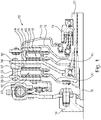
- Fig. 1 The basic structure of a multi-plate dual clutch 10 is shown in Fig. 1 seen.
- multi-plate dual clutch 10 has a first part clutch 12 for coupling a drive shaft 14 with a first transmission input shaft 16 and a second part clutch 18 for coupling the drive shaft 14 with a concentric with the first transmission input shaft 16 arranged second transmission input shaft 20.
- the first partial clutch 12 has a first counter-plate 22 and a relative to the first counter-plate 22 axially displaceable first pressure plate 24. Between the first counter-plate 22 and the first pressure plate 24, an axially displaceable first intermediate plate 26 is provided. Between the first counter-plate 22 and the first intermediate plate 26 and between the first intermediate plate 26th and the first pressure plate 24 are each axially displaceable first friction linings 28 of a first clutch disc 30 is provided.
- the first clutch plate 30 is rotatably connected to the first transmission input shaft 16.
- the second partial clutch 18 has a second counter-plate 34 and a second pressure plate 36 that is axially displaceable relative to the second counter-plate 34. Between the second counter-plate 34 and the second pressure plate 36 an axially displaceable second intermediate plate 38 is provided. Between the second pressure plate 36 and the second intermediate plate 38 and between the second intermediate plate 38 and the second counter-plate 34 each axially displaceable second friction linings 40 of a second clutch disc 42 are provided. The second clutch plate 42 is rotatably connected to the second transmission input shaft 20.
- the first pressure plate 24 is connected via a first Anpressplatten Wegstellfeder 44 with the first counter-plate 22, while the first intermediate plate 26 is connected via a first intermediate plate return spring 46 with the first counter-plate 22.
- the second pressure plate 36 is connected via a second Anpressplatten Wegstellfeder 48 with the second counter-plate 34, while the second intermediate plate 38 is connected via a second intermediate plate return spring 50 with the second counter-plate 34.
- first actuating element 70 designed, for example, as a plate-spring-type lever spring or actuating pot
- first pressure plate 24 and indirectly the at least one first intermediate plate 26 can be acted upon by an actuating force for displacing the first pressure plate 24, while using a second lever spring or actuating pot configured as a plate-spring-like lever spring, for example Actuator 72, the second pressure plate 26 and indirectly, the at least one second intermediate plate 38 can be acted upon with an actuating force for displacing the second pressure plate 26.
- the actuation force may be provided, for example, by a hydraulic actuation system 74.
- the intermediate plates 26, 38 and the pressure plates 24, 36 connected via leaf springs as configured return springs 44, 46, 48, 50 with the relative to the partial coupling 12, 18 fixed parts.
- the first pressure plate 24 is connected via a first Anpressplatten Wegstellfeder 44 with the first counter-plate 22, while the first intermediate plate 26 is connected via a first intermediate plate return spring 46 with the first counter-plate 22.
- the second pressure plate 36 is connected via a second Anpressplatten Wegstellfeder 48 with the second Counter-plate 34 is connected, while the second intermediate plate 38 is connected via a second intermediate plate return spring 50 with the second counter-plate 34.
- the return springs 44, 46, 48, 50 serve to center the plates 24, 26, 36, 38 and to transmit torque.
- the return springs 44, 46, 48, 50 in the axial direction are elastic and thus allow a guided axial displacement of the intermediate plates 26, 38 and pressure plates 24, 36.
- Both plates 24, 26; 36, 38 have a plurality of circumferentially distributed as leaf springs or leaf spring packages designed return springs 44, 46, 48, 50.
- the intermediate plate 26, 38 is supported via a connected to the intermediate plate 26, 38 support member 74, 76 on one or more leaf springs of the Anpressplatten Wegstellfedern 44, 48 of the pressure plate 24, 36 from.
- the basic principle shows the Fig. 2 in which schematically the three plates pressure plate 24, 36, intermediate plate 26, 38 and counter-plate 22, 34 are shown by way of example, between which two designed as a lining friction linings 28, 40 of the clutch disc 30, 42 are located. Both the pressure plate 24, 36 and the intermediate plate 26, 38 is connected via its own return springs 44, 46, 48, 50 with the relative to the partial coupling 12, 18 fixed counter-plate 22, 34.
- the power transmission and the centering takes place each directly between the movable plate (pressure plate 24, 36 or intermediate plate 26, 38) and the fixed relative to the partial clutch components (shown here by the counter-plate 22, 34) without tangential forces and centering of one of movable plates 24, 26; 36, 38 on the other movable plate 26, 24; 38, 36 is transmitted.
- the Fig. 2 represents only a section of a simplified settlement, only one return spring is visible, which holds the pressure plate 24, 36 and the back plate 22, 34.
- it is useful to distribute a plurality of return springs 44, 46, 48, 50 on the circumference, each on one side to the movable plate 24, 26; 36, 38 and on the other side are connected to a component fixed relative to the partial coupling.
- FIG. 3 clearly seen that the Anpressplatten Wegstellfedern 44, 48 of the pressure plates 24, 36 and the intermediate plate return springs 46, 50 of the intermediate plates 26, 38 seen on the circumference alternately between the main attachment points, where the counter plates 22, 34 of the two sub-couplings 12, 18 by means of a arranged as a rivet connection main connection element 56 are connected to each other, are arranged.
- the counter-plates are spaced apart via an intermediate piece 32, which is riveted by means of the main connecting element 56 with the first counter-plate 22 and the second counter-plate 34.
- the leaf spring assemblies of the Anpressplatten Wegstellfedern 44, 48 which hold the pressure plates 24, 36 of the two part clutches 12, 18, axially arranged in front of each other.
- the Fig. 4 shows another embodiment in which the main attachment points of the main connecting elements 56 are also not covered by the return springs 44, 46, 48, 50, the Anpressplatten Wegstellfedern 44, 48 of a sub-clutch 12, 18 but axially in front of the intermediate plate return springs 46, 50 of the other sub-clutch 18th , 12 lie.
- This arrangement makes it possible to make the partial coupling 12, 18 radially outside in the area of the return springs 44, 46, 48, 50 axially very short.
- FIG. 5 Another leaf spring arrangement shows Fig. 5 ,
- the Anpressplatten Wegstellfedern 44, 48 and the intermediate plate restoring springs 46, 50 are offset in the circumferential direction of each other.
- the attachment point between the intermediate plate 26, 38 and its intermediate plate return springs 46, 50 can also be used simultaneously as a support position of the intermediate plate 26, 38 on the pressure plate return springs 44, 48.
- the rivets which connect the intermediate plate restoring spring 46, 50 to the intermediate plate 26, 38 are provided with a contact geometry for the pressure plate return springs (head with a central rounded extension).
- the rivets that connect the Anpressplatten Wegstellfedern 44, 48 with a relative to the partial coupling 12, 18 fixed component lie on a larger circle than the rivet positions of the compound of the intermediate plate return springs 46, 50 and the fixed parts, the riveting of the Anpressplatten Wegstellfedern 44, 48 is not exactly behind the intermediate plate return springs 46, 50.
- the middle part of Intermediate plate restoring springs 46, 50 radially inwardly displaced inwardly than the riveting points by means of a radially outwardly opened intermediate plate return spring taper 58, 60, may facilitate the axial accessibility of the pressure plate leaf spring riveting.
- multi-plate dual couplings 10 in which not all of the exterior can be used for the return springs 44, 46, 48, 50 and the main links 56 connecting the counter plates 22, 34.
- the leaf spring assemblies of the return springs 44, 46, 48, 50 are to be arranged very compact and close to each other.
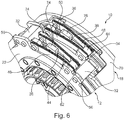
- Two embodiments, which use a similar basic principle, to arrange the return springs 44, 46, 48, 50 close together, show the Fig. 6 and 7 , In each case, the leaf spring assemblies of the return springs 44, 46, 48, 50 for the pressure plate 24, 36 and for the intermediate plate 26, 38 of the same sub-coupling 12, 18 are arranged directly axially in front of each other.
- FIG. 6 There are four return springs 44, 46, 48, 50 axially staggered between two main attachment points of the main fasteners 56. If per plate in each case three return springs 44, 46; 48, 50 are arranged distributed on the circumference of the partial coupling 12, 18, all return springs 44, 46, 48, 50 in three leaf spring arrangements in the manner shown compact accommodate. On the circumference of the partial clutch 12, 18 then arise between the leaf spring arrangements large bodies in which there are no return springs 44, 46, 48, 50 are. These locations can then be used for other coupling components or components connected to the partial coupling 12, 18.
- the embodiment that is in the Fig. 7 uses for the return springs 44, 46, 48, 50, the same space-saving attachment principle. However, in each case only one intermediate plate restoring spring 46, 50 and a pressure plate restoring spring 44, 48 of a partial coupling 12, 18 are arranged axially in front of each other.
- the return springs 44, 46, 48, 50 of the other sub-clutch 18, 12 are arranged in the same way, but are located on an offset on the circumference of the sub-clutch 12, 18 angular position. This also creates clearances on the circumference of the multi-plate dual clutch 10, which can be used for other purposes or other components.
- the return springs 44, 46, 48, 50 are always arranged radially over the plates 24, 26, 36, 38 with which they are connected. Characterized in the figure, the assignment of the return springs 44, 46, 48, 50 to their plates 24, 26, 36, 38 and the function of the return springs 44, 46, 48, 50 easier to see.
- the leaf spring mounting tabs of the plates 24, 26, 36, 38 to which the return springs 44, 46, 48, 50 are riveted or otherwise secured, as well as the support tabs 74, 76 configured as support tabs may not just be straight but also be made bent. As a result, the return springs 44, 46, 48, 50 can be arranged in a slightly different position than the plates 24, 26, 36, 38 connected to them.
- the areas released on the circumference of the multi-disc dual clutch 10 can also be used for further intermediate plate return springs 46, 50 for the partial clutches 12, 18, which have more than two lining rings 52, 54 and more than one intermediate plate 26, 38 per partial coupling 12, 18 further intermediate plates 26, 38 to be arranged.
- the central part of the Anpressplatten Wegstellfeder may be narrower than the attachment areas.
- the intermediate plate restoring springs 46, 50 are arched radially outward, waisted, and the attachment areas are not centered but displaced radially inward at the intermediate plate restoring springs 46. 50 formed.
- the return springs 44, 46, 48, 50 are of different lengths.
- the attachment means, which connect the return springs 44, 46, 48, 50 to the intermediate plate 26, 38 or the pressure plate 24, 36 are not directly in front of each other and can at least partially pivot past each other in the movement of the plates 24, 26, 36, 38 ,
- waisted leaf springs 44, 46, 48, 50 can solve various space difficulties.
- the important for the mounting axial accessibility to a riveted joint is made possible.
- the Fig. 10 shows that already from the Fig. 3 known embodiment from another perspective.
- the second pressure plate return springs 48 of the transmission-side second partial clutch 18 are here waisted in two places to allow nesting with the designed as a pressure pot second actuator.
- the fact that the waisted leaf springs of the return springs 44, 46, 48, 50 have areas of different widths can also be used for the voltage optimization of the return springs 44, 46, 48, 50.
- the leaf spring is made wider than at less stressed areas.
- the attachment areas to which the return springs 44, 46, 48, 50 are connected, in particular riveted, and in the immediate vicinity of high bending loads act on the return springs 44, 46, 48, 50 are therefore wider than the narrow less stressed areas.
- the area in which the intermediate plate 26, 38 is supported on the Anpressplatten Wegstellfedern 44, 48 is also reinforced by its wide shape. By reinforcing the leaf spring cross-section in this highly stressed area, the stresses which are caused by the force acting on the contact pressure restoring springs 44, 48 by the support element 74, 76 can be reduced.
- the leaf springs of the return springs 44, 46, 48, 50 are used because of their low friction, especially in dry double clutches. All presented here Arrangement and design concepts can also be used in wet-running clutches.
Landscapes
- Engineering & Computer Science (AREA)
- General Engineering & Computer Science (AREA)
- Mechanical Engineering (AREA)
- Mechanical Operated Clutches (AREA)
- Hydraulic Clutches, Magnetic Clutches, Fluid Clutches, And Fluid Joints (AREA)
Description
Die Erfindung betrifft eine Mehrscheibendoppelkupplung mit deren Hilfe eine Antriebswelle eines Kraftfahrzeugmotors über eine erste Mehrscheibenkupplung, insbesondere Zweischeibenkupplung, und/oder eine zweite Mehrscheibenkupplung, insbesondere Zweischeibenkupplung, mit mindestens einer ersten Getriebeeingangswelle beziehungsweise einer zweiten Getriebeeingangswelle gekuppelt werden kann.The invention relates to a multi-plate dual clutch with the aid of which a drive shaft of an automotive engine via a first multi-plate clutch, in particular two-disc clutch, and / or a second multi-plate clutch, in particular two-disc clutch, can be coupled with at least one first transmission input shaft or a second transmission input shaft.
Trockene Doppelkupplung verfügen nach derzeitigem Stand der Technik meist über eine Scheibe je Teilkupplung. Diese Scheiben besitzen je zwei Reibflächen mit denen sie an ihren Nachbarbauteilen (z.B. Anpressplatte und Zentralpatte oder Gegenplatte) anliegen, wenn sie zur Momentenübertragung von der Kupplung eingespannt werden, und bilden so mit der Kupplung zwei Reibstellen aus. Das übertragbare Moment einer Kupplung lässt sich auch bei gleicher Anpresskraft, gleichem Durchmesser und gleichen Reibverhältnissen (Reibwert) steigern, indem man die Anzahl der Reibstellen erhöht. Dieses Prinzip wird häufig bei Lamellenkupplungen eingesetzt, wie sie beispielsweise auch bei nasslaufenden Doppelkupplungen verwendet werden. Als trockenlaufende Kupplungen sind Lamellenkupplungen für Fahrzeuganwendungen meist ungeeignet. Ohne Öl, das die Kupplung kühlt, überhitzen die dünnen Lamellen schnell, da sie zu wenig Wärmekapazität aufweisen. Außerdem lüften Lamellenkupplungen meist nicht richtig, wenn die Reibstellen zwischen den Lamellen und den Lamellenträgern nicht durch das Öl geschmiert werden. Um die Vorteile vieler Reibstellen pro Kupplung auch bei trockenlaufenden Doppelkupplungen nutzen zu können, gibt es mittlerweile Erfindungen, die einen Weg aufzeigen zwei oder mehr Scheiben in eine Teilkupplung zu integrieren und dies mit für Trockenkupplungen bewährten Teilen und Funktionsprinzipien realisieren.Dry dual clutch have the current state of the art usually one disc per part clutch. These discs each have two friction surfaces with which they bear against their neighboring components (for example, pressure plate and central plate or counter-plate) when they are clamped by the clutch for torque transmission, thus forming two friction points with the clutch. The transmittable torque of a clutch can be increased even with the same contact pressure, the same diameter and the same friction conditions (coefficient of friction) by increasing the number of friction points. This principle is often used in multi-plate clutches, as used for example in wet-running double clutches. As dry running clutches multi-plate clutches are usually unsuitable for vehicle applications. Without oil, which cools the clutch, the thin blades quickly overheat because they have too little heat capacity. In addition, multi-plate clutches are usually not ventilated properly if the friction points between the plates and the plate carriers are not lubricated by the oil. In order to use the advantages of many friction points per clutch even when running dry dual clutches, there are now inventions that show a way to integrate two or more discs in a part clutch and realize this with proven parts for dry clutches and operating principles.
Aus
Es besteht ein ständiges Bedürfnis im Antriebsstrang eines Kraftfahrzeugs mit Hilfe einer leicht montierbaren Reibungskupplung ein besonders hohes Drehmoment bei unterschiedlichen Bauformen des Antriebsstrangs übertragen zu können.Out
There is a constant need in the drive train of a motor vehicle with the help of an easily mounted friction clutch to be able to transmit a particularly high torque in different types of powertrain.
Andere Doppelkupplungen sind aus der
Die Lösung der Aufgabe erfolgt erfindungsgemäß durch eine Mehrscheibendoppelkupplung mit den Merkmalen des Anspruchs 1. Bevorzugte Ausgestaltungen der Erfindung sind in den Unteransprüchen angegeben, die jeweils einzeln oder in Kombination einen Aspekt der Erfindung darstellen können.
Erfindungsgemäß ist eine Mehrscheibendoppelkupplung zum Kuppeln einer Antriebswelle eines Kraftfahrzeugmotors mit einer ersten Getriebeeingangswelle und/oder einer zweiten Getriebeeingangswelle vorgesehen mit einer ersten Teilkupplung zum Kuppeln der Antriebswelle mit der ersten Getriebeeingangswelle, wobei die erste Teilkupplung eine erste Gegenplatte, mindestens eine über eine erste Zwischenplattenrückstellfeder mit der ersten Gegenplatte verbundene relativ zur ersten Gegenplatte axial verlagerbare erste Zwischenplatte und eine über eine erste Anpressplattenrückstellfeder mit der ersten Gegenplatte verbundene relativ zur ersten Gegenplatte und zur ersten Zwischenplatte axial verlagerbare erste Anpressplatte zum Verpressen von ersten Reibbelägen einer ersten Kupplungsscheibe zwischen der ersten Gegenplatte und der ersten Zwischenplatte sowie zwischen der ersten Zwischenplatte und der ersten Anpressplatte aufweist, einer zweiten Teilkupplung zum Kuppeln der Antriebswelle mit der zweiten Getriebeeingangswelle, wobei die zweite Teilkupplung eine zweite Gegenplatte, mindestens eine über eine zweite Zwischenplattenrückstellfeder mit der zweiten Gegenplatte verbundene relativ zur zweiten Gegenplatte axial verlagerbare zweite Zwischenplatte und eine über eine zweite Anpressplattenrückstellfeder mit der zweiten Gegenplatte verbundene relativ zur zweiten Gegenplatte und zur zweiten Zwischenplatte axial verlagerbare zweite Anpressplatte zum Verpressen von zweiten Reibbelägen einer zweiten Kupplungsscheibe zwischen der zweiten Gegenplatte und der zweiten Zwischenplatte sowie zwischen der zweiten Zwischenplatte und der zweiten Anpressplatte aufweist, und einem die erste Gegenplatte mit der zweiten Gegenplatte drehfest verbindenden Hauptverbindungselement, insbesondere Nietverbindung, wobei das Hauptverbindungselement zur ersten Anpressplattenrückstellfeder, zur ersten Zwischenplattenrückstellfeder, zur zweiten Anpressplattenrückstellfeder und zur zweiten Zwischenplattenrückstellfeder in Umfangsrichtung und/oder in radialer Richtung versetzt angeordnet ist.Other double clutches are from the
The object is achieved according to the invention by a multi-plate double clutch with the features of claim 1. Preferred embodiments of the invention are specified in the subclaims, which individually or in combination may constitute an aspect of the invention.
According to the invention, a multi-plate dual clutch for coupling a drive shaft of an automotive engine with a first transmission input shaft and / or a second transmission input shaft is provided with a first part clutch for coupling the drive shaft with the first transmission input shaft, wherein the first part clutch a first counter plate, at least one via a first intermediate plate return spring with the first counter-plate connected relative to the first counter-plate axially displaceable first intermediate plate and connected via a first Anpressplattenrückstellfeder with the first counter-plate axially displaceable relative to the first counter-plate and the first intermediate plate first pressure plate for pressing first friction linings of a first clutch disc between the first counter-plate and the first intermediate plate and between the first intermediate plate and the first pressure plate, a second part coupling for coupling the drive shaft with the second transmission input shaft, wherein the second sub-coupling a second counter-plate, at least one connected via a second intermediate plate return spring to the second counter-plate axially displaceable relative to the second counter-plate second intermediate plate and connected via a second Anpressplattenrückstellfeder with the second counter-plate axially displaceable relative to the second counter-plate and the second intermediate plate second pressure plate for pressing second friction linings of a second clutch disc between the second counter-plate and the second intermediate plate and between the second intermediate plate and the second pressure plate The main connection element to the first Anpressplattenrückstellfeder, the first Zwischenplattenrückstellfeder, the second Anpressplattenrückstellfeder and the second intermediate plate return spring in the circumferential direction and / or in the radial direction is arranged staggered, the first counter-plate with the second counter-plate.
Mit Hilfe der jeweiligen Zwischenplatte ist es möglich zwei weitere Reibflächen zum Verpressen von Reibbelägen der zugeordneten Kupplungsscheibe bereitzustellen, so dass sich mit der Zwischenplatte die Anzahl der Reibflächen der jeweiligen Teilkupplung entsprechend erhöhen lässt. Durch die erhöhte Anzahl der Reibflächen kann ein entsprechend erhöhtes Drehmoment übertragen werden. Zusätzlich oder alternativ kann die auf die jeweilige Anpressplatte aufzubringende Anpresskraft reduziert werden, um ein bestimmtes maximales Drehmoment noch übertragen zu können. Zusätzlich oder alternativ kann der Außenradius der Gegenplatte und/oder der Anpressplatte verringert werden, um ein bestimmtes maximales Drehmoment noch übertragen zu können. Durch den geringeren Außenradius kann das Massenträgheitsmoment der jeweiligen Teilkupplung reduziert werden und radial Bauraum eingespart werden. Durch das reduzierte Massenträgheitsmoment eignet sich die Mehrscheibendoppelkupplung insbesondere für Anwendungen mit einem sportlichen und/oder dynamischen Fahrverhalten und/oder zur Reduzierung eines Kraftstoffverbrauchs eines Kraftfahrzeugs. Gleichzeitig kann die Anpresskraft über ein der jeweiligen Anpressplatte zugeordnetes Betätigungselement, beispielsweise ein in der Art einer Tellerfeder ausgestaltetes Hebelelement, in die jeweilige Anpressplatte eingeleitet werden. Dadurch kann sich zwischen einem, insbesondere hydraulischen, Betätigungssystem zur Bereitstellung einer Betätigungskraft und der an dem Reibbelag der Kupplungsscheibe angreifenden Anpresskraft eine Hebelübersetzung ergeben, wodurch sich insbesondere die Betätigungskraft verstärken lässt. Dadurch braucht das Betätigungssystem für eine bestimmte Anpresskraft nur eine entsprechend geringere Betätigungskraft zu erzeugen, die vorzugsweise so gering ist, dass diese Betätigungskraft sogar von der Antriebswelle des Kraftfahrzeugmotors abgestützt werden kann. Dies ermöglicht zusätzliche konstruktive Freiheiten, die beispielsweise für eine verbesserte Montierbarkeit der Mehrscheibendoppelkupplung genutzt werden können. Durch die mit Hilfe des jeweiligen Betätigungselements betätigbare mindestens eine Zwischenplatte aufweisende Teilkupplung kann auch bei einer Reduzierung der zum Betätigen der Teilkupplung erforderlichen Betätigungskraft die Anzahl der effektiven Reibflächen erhöht werden, so dass bei geringen auftretenden Kräften eine Übertragung von großen Drehmomenten in einem Antriebsstrang eines Kraftfahrzeugs ermöglicht ist.With the help of the respective intermediate plate, it is possible to provide two further friction surfaces for pressing friction linings of the associated clutch disc, so that the number of friction surfaces of the respective part clutch can be correspondingly increased with the intermediate plate. Due to the increased number of friction surfaces, a correspondingly increased torque can be transmitted. Additionally or alternatively, the applied to the respective pressure plate contact pressure can be reduced in order to transmit a certain maximum torque can still. Additionally or alternatively, the outer radius of the counter-plate and / or the pressure plate can be reduced in order to transmit a certain maximum torque can still. Due to the smaller outer radius, the moment of inertia of the respective sub-coupling can be reduced and radial space can be saved. Due to the reduced mass moment of inertia, the multi-disc dual clutch is particularly suitable for applications with a sporty and / or dynamic driving behavior and / or for reducing fuel consumption of a motor vehicle. At the same time, the pressing force can be introduced into the respective pressure plate via an actuating element assigned to the respective pressure plate, for example a lever element configured in the manner of a plate spring. As a result, there can be a lever transmission between a, in particular hydraulic, actuating system for providing an actuating force and the contact force acting on the friction lining of the clutch disk, whereby in particular the actuating force can be increased. As a result, the actuating system only needs a correspondingly lower actuation force for a specific contact force generate, which is preferably so low that this actuating force can be supported even by the drive shaft of the motor vehicle engine. This allows additional design freedom, which can be used, for example, for improved mountability of the multi-disc dual clutch. By actuatable with the aid of the respective actuating element at least one intermediate plate having partial coupling, the number of effective friction surfaces can be increased even with a reduction in the actuation of the partial clutch actuating force, so that at low forces occurring transmission of large torques in a drive train of a motor vehicle is.
Dadurch, dass das zum Verbinden der beiden Gegenplatten der Teilkupplungen vorgesehene Hauptverbindungselement nicht in axialer Richtung von einer der, insbesondere als Blattfeder ausgestalteten, Rückstellfedern der Teilkupplungen verdeckt ist, sondern zu den Rückstellfedern der Teilkupplungen versetzt angeordnet ist, ist es möglich die Teilkupplungen als vormontierte Baueinheiten in der Mehrscheibendoppelkupplung zu verbauen. Dadurch kann die Mehrscheibendoppelkupplung montiert werden, indem die beiden Teilkupplungen mit Hilfe des mindestens einen Hauptverbindungselements an einer oder vorzugsweise mehreren Hauptverbindungsstellen miteinander direkt oder indirekt, beispielsweise über ein eine axiale Distanz überbrückendes Zwischenstück, verbunden werden. Die Montage der Mehrscheibendoppelkupplung ist dadurch vereinfacht. Durch das zu den mehreren Rückstellfedern der jeweiligen als Mehrscheibenkupplung ausgestalteten Teilkupplungen versetzt angeordnete Hauptverbindungselement ist eine Übertragung eines besonders hohen Drehmoments bei unterschiedlichen Bauformen eines Antriebsstrangs eines Kraftfahrzeugs mit Hilfe einer leicht montierbaren Reibungskupplung ermöglicht.Because the main connecting element provided for connecting the two opposing plates of the partial clutches is not covered in the axial direction by one of the return clutches of the partial clutches designed as a leaf spring, but is offset relative to the return springs of the partial clutches, it is possible to use the partial clutches as preassembled structural units in the multi-plate dual clutch. Thereby, the multi-disc dual clutch can be mounted by the two part couplings by means of at least one main connection element at one or more main joints with each other directly or indirectly, for example via an axial distance bridging spacer, are connected. The assembly of the multi-disc dual clutch is simplified. By the plurality of return springs of the respective configured as a multi-plate clutch partial clutches arranged main connecting element transmission of a particularly high torque in different designs of a drive train of a motor vehicle by means of an easily mounted friction clutch is possible.
Die jeweilige Kupplungsscheibe kann zwischen den aufeinander zu weisenden Platten der zugeordneten Teilkupplung, insbesondere an voneinander wegweisenden axialen Stirnflächen eine Belagfederung aufweisen, über die jeweils ein Reibbelag mit der Kupplungsscheibe verbunden ist, wobei der jeweilige Reibbelag mit der zugehörigen Gegenplatte und/oder Anpressplatte und/oder Zwischenplatte reibschlüssig in Kontakt kommen kann, um die jeweilige Teilkupplung zu schließen. Der zwischen der Gegenplatte und der Zwischenplatte vorgesehene Reibbelag und der zwischen der Zwischenplatte und der Anpressplatte vorgesehene Reibbelag können in axialer Richtung relativ zueinander bewegbar sein, wobei es möglich ist, das der eine Reibbelag in axialer Richtung unbeweglich und der andere Reibbelag in axialer Richtung verschiebbar an der Kupplungsscheibe angebunden ist. Die jeweilige Kupplungsscheibe kann über eine Verzahnung mit der jeweiligen Getriebeeingangswelle drehfest, aber axial beweglich verbunden sein. Die Mehrscheibendoppelkupplung kann insbesondere mit einem motorseitig vorgelagerten und/oder getriebeseitig nachgelagerten Drehschwingungsdämpfer, insbesondere Zweimassenschwungrad und/oder Fliehkraftpendel und/oder Massependel, direkt oder indirekt verbunden sein. Insbesondere kann das Fliehkraftpendel und/oder ein Massependel direkt in die Kupplung integriert und/oder an ihr befestigt sein. Ferner kann die jeweilige Kupplungsscheibe insbesondere mit Hilfe eines Scheibendämpfers gedämpft sein. Die Mehrscheibendoppelkupplung kann insbesondere über eine starre Scheibe ("Driveplate") und/oder eine biegbare und/oder in axialer Richtung flexible Scheibe ("Flexplate") mit der Antriebswelle verbunden sein, wobei die Scheibe Drehmomente übertragen kann, um in die Doppelkupplung das Drehmoment der Antriebswelle einleiten zu können. Durch die flexible Ausgestaltung der Scheibe können auftretende Schwingungen ganz oder teilweise gedämpft oder getilgt werden. Zusätzlich oder alternativ kann die Mehrscheibendoppelkupplung über mindestens ein Federelement, insbesondere Blattfeder, mit der Antriebswelle verbunden sein. Das Federelement kann insbesondere Axialschwingung dämpfen und/oder ein Taumeln der Antriebswelle ausgleichen und dabei gleichzeitig ein Drehmoment übertragen.The respective clutch disc may have a lining suspension between the mutually facing plates of the associated sub-coupling, in particular on facing away from each axial end faces, via which in each case a friction lining is connected to the clutch disc, wherein the respective friction lining with the associated counter-plate and / or pressure plate and / or Intermediate plate can come into frictional engagement to close the respective part clutch. The provided between the backing plate and the intermediate plate friction lining and provided between the intermediate plate and the pressure plate friction lining can in the axial direction be movable relative to each other, it being possible that one friction lining immovably in the axial direction and the other friction lining in the axial direction is slidably connected to the clutch disc. The respective clutch disc can be rotatably connected via a toothing with the respective transmission input shaft, but axially movable. The multi-disc dual clutch can be directly or indirectly connected, in particular, to a torsion vibration damper, in particular dual-mass flywheel and / or centrifugal force pendulum and / or mass pendulum, arranged upstream and / or downstream of the engine. In particular, the centrifugal pendulum and / or a mass pendulum can be integrated directly into the coupling and / or attached to it. Furthermore, the respective clutch disc can be damped in particular by means of a disc damper. The multi-disc dual clutch can in particular be connected to the drive shaft via a rigid disk ("drive plate") and / or a flexible and / or axially flexible disk ("flexplate"), wherein the disk can transmit torques in order to torque the dual clutch to be able to initiate the drive shaft. Due to the flexible design of the disc occurring vibrations can be completely or partially damped or eliminated. Additionally or alternatively, the multi-disc dual clutch via at least one spring element, in particular leaf spring, be connected to the drive shaft. The spring element can in particular dampen axial vibration and / or compensate for a wobble of the drive shaft while at the same time transmitting a torque.
Die erste Gegenplatte und die zweite Gegenplatte können als voneinander verschiedene separate Bauteile ausgestaltet sein. Insbesondere ist genau eine erste Zwischenplatte oder es sind genau zwei erste Zwischenplatten oder genau drei erste Zwischenplatten vorgesehen. Vorzugsweise ist genau eine zweite Zwischenplatte oder es sind genau zwei zweite Zwischenplatten oder genau drei zweite Zwischenplatten vorgesehen. Bei jeweils einer Zwischenplatte und getrennt vorgesehenen Gegenplatten ergibt sich eine Doppelkupplung nach dem "sechs-Platten-Design Bei jeweils zwei Zwischenplatten und getrennt vorgesehenen Gegenplatten ergibt sich eine Doppelkupplung nach dem "acht-Platten-Design". Vorzugsweise sind die erste Getriebeeingangswelle und die zweite Getriebeeingangswelle koaxial zueinander angeordnet. Insbesondere ist die innere Getriebeeingangswelle, insbesondere die erste Getriebeeingangswelle, an der Antriebswelle gelagert. Vorzugsweise weist die Antriebswelle an einer axialen Stirnseite eine Vertiefung auf, in welche die innere Getriebeeingangswelle teilweise hineinragt und beispielsweise über ein Pilotlager an der Antriebswelle gelagert sein kann.The first counter-plate and the second counter-plate may be configured as separate from each other separate components. In particular, exactly one first intermediate plate or exactly two first intermediate plates or exactly three first intermediate plates are provided. Preferably, exactly one second intermediate plate or exactly two second intermediate plates or exactly three second intermediate plates are provided. In each case an intermediate plate and separately provided counter-plates results in a double clutch after the "six-plate design With two intermediate plates and separately provided counter plates results in a double clutch on the" eight-plate design. "Preferably, the first transmission input shaft and the second In particular, the inner transmission input shaft, in particular the first transmission input shaft, is mounted on the drive shaft on an axial end face on a recess into which the inner transmission input shaft partially protrudes and may be mounted for example via a pilot bearing on the drive shaft.
Es ist insbesondere ein erstes Betätigungselement zum Verlagern der ersten Anpressplatte und ein zweites Betätigungselement zum Verlagern der zweiten Anpressplatte vorgesehen. Das Betätigungselement kann insbesondere als Hebelfeder ausgestaltetes sein, die bei Einleitung einer Betätigungskraft elastisch verbogen werden kann. Das Betätigungselement kann beispielsweise in der Art einer Tellerfeder ausgestaltet sein. Das Betätigungselement kann einen ringförmig in Umfangsrichtung umlaufenden Tellerfederkörper aufweisen, dessen Konizität sich bei einem Schwenken des Betätigungselements um einen in Umfangsrichtung verlaufenden Schwenkpunkt verändern kann. Von dem Tellerfederkörper können Federzungen nach radial innen abstehen, so dass an einem radial inneren Ende der Federzungen die Betätigungskraft eingeleitet werden kann. Die Betätigungskraft kann von einem insbesondere hydraulischen Betätigungssystem aufgebracht werden, das insbesondere einen ersten Ringzylinder zum Verschwenken des ersten Betätigungselements mit Hilfe eines in dem ersten Ringzylinder axial geführten ersten Betätigungskolbens und einen konzentrisch zum ersten Ringzylinder vorgesehenen zweiten Ringzylinder zum Verschwenken des zweiten Betätigungselements mit Hilfe eines in dem zweiten Ringzylinder axial geführten zweiten Betätigungskolbens aufweist. Zwischen dem ersten Betätigungskolben und dem ersten Betätigungselement kann ein erstes Ausrücklager und zwischen dem zweiten Betätigungskolben und dem zweiten Betätigungselement ein zweites Ausrücklager angeordnet sein. Besonders bevorzugt ist eine erste Nachstelleinrichtung zum Nachstellen eines verschleißbedingten Fehlabstands der ersten Anpressplatte zur ersten Gegenplatte und/oder eine zweite Nachstelleinrichtung zum Nachstellen eines verschleißbedingten Fehlabstands der zweiten Anpressplatte zur zweiten Gegenplatte vorgesehen. Die jeweilige Nachstelleinrichtung kann insbesondere zwischen dem zugeordnetem Betätigungselement und einem Kupplungsdeckel der zugeordneten Teilkupplung oder zwischen dem zugeordnetem Betätigungselement und der zugeordneten Anpressplatte vorgesehen sein. Die jeweilige Nachstelleinrichtung weist insbesondere einen in Umfangsrichtung vorgespannten Nachstellring auf, der Teil eines Rampensystems ist und bei einem hinreichend großen Hubweg der nachzustellenden Anpressplatte sich verdrehen kann, um einen ursprünglichen Hubweg der Anpressplatte nachstellen zu können. Zusätzlich oder alternativ kann ein Nachstellen eines verschleißbedingten Fehlabstands auch durch einen mitwandernden Anschlag des Betätigungssystems realisiert werden. Der mitwandernde Anschlag kann bei einem entsprechend großen Ausrückweg des jeweiligen Betätigungskolben mitgenommen werden und dadurch bei einem Nachlassen der aufgebauten Betätigungskraft den Betätigungskolben nur um eine entsprechend geringere Wegstreckt in den zugeordneten Ringzylinder einfahren lassen, so dass bei einer erneuten Betätigung der Betätigungskolben um eine entsprechend geringere Wegstrecke ausgefahren werden muss.In particular, a first actuating element for displacing the first pressure plate and a second actuating element for displacing the second pressure plate are provided. The actuating element may in particular be configured as a lever spring, which can be bent elastically upon initiation of an actuating force. The actuator may be configured, for example, in the manner of a plate spring. The actuating element may have an annular circumferential spring plate spring body whose conicity may change upon pivoting of the actuating element about a pivot point extending in the circumferential direction. From the disc spring body spring tongues can protrude radially inward, so that the actuating force can be initiated at a radially inner end of the spring tongues. The actuating force can be applied by a particular hydraulic actuating system, in particular a first annular cylinder for pivoting the first actuating element by means of a first annular piston axially guided first actuating piston and concentric with the first ring cylinder provided second annular cylinder for pivoting the second actuating element by means of an in Having the second ring cylinder axially guided second actuating piston. Between the first actuating piston and the first actuating element, a first release bearing and between the second actuating piston and the second actuating element, a second release bearing can be arranged. Particularly preferably, a first adjusting device for adjusting a wear-related misalignment of the first pressure plate to the first counter-plate and / or a second adjusting device for adjusting a wear-related misalignment of the second pressure plate to the second counter plate is provided. The respective adjusting device may in particular be provided between the associated actuating element and a clutch cover of the associated partial clutch or between the associated actuating element and the associated pressure plate. The respective adjusting device has in particular a circumferentially biased adjusting ring, which is part of a ramp system and can rotate at a sufficiently large stroke of nachzustellenden pressure plate to an original Be able to adjust stroke of the pressure plate. Additionally or alternatively, an adjustment of a wear-related incorrect distance can also be realized by a mitwandernden stop of the actuation system. The mitwandernde stop can be taken in a correspondingly large Ausrückweg of the respective actuating piston and thereby retract the actuating piston only a correspondingly lower Wegstreckt in a decrease in the associated operating force at a decrease in the actuation force, so that upon renewed actuation of the actuating piston by a correspondingly smaller distance must be extended.
Insbesondere sind die erste Anpressplattenrückstellfeder und die zweite Anpressplattenrückstellfeder im Wesentlichen vollständig oder teilweise und/oder die erste Zwischenplattenrückstellfeder und die zweite Zwischenplattenrückstellfeder im Wesentlichen vollständig oder teilweise in axialer Richtung hintereinander angeordnet. Es ist möglich, dass das aus der ersten Anpressplattenrückstellfeder und der zweite Anpressplattenrückstellfeder zusammengesetzte Federpaket und das aus der ersten Zwischenplattenrückstellfeder und der zweiten Zwischenplattenrückstellfeder zusammengesetzte Federpaket im Wesentlichen vollständig oder teilweise in axialer Richtung hintereinander angeordnet sind oder vollständig in Umfangsrichtung zueinander versetzt angeordnet sind. Die zumindest teilweise hintereinander angeordneten Rückstellfedern können in Umfangsrichtung an hinreichend vielen Stellen Bereiche vorsehen, in denen keine Rückstellfedern angeordnet sind und in denen das Hauptverbindungselement und/oder andere Bauteile der Mehrscheibendoppelkupplung und/oder des Antriebstrangs des Kraftfahrzeugs vorgesehen werden können. Da die Zwischenplattenrückstellfedern einen geringeren maximalen axialen Betätigungsweg als die Anpressplattenrückstellfeder überstreichen, können die Zwischenplattenrückstellfedern kürzer ausgeführt werden als die Anpressplattenrückstellfedern. Indem die kurzen Zwischenplattenrückstellfedern und die langen Anpressplattenrückstellfedern axial voreinander angeordnet werden können lässt sich der Bauraum in Umfangsrichtung besonders effizient nutzen, beispielsweise zur Schaffung von genügend Bauraum für die Hauptbefestigungselemente.In particular, the first pressure plate restoring spring and the second pressure plate restoring spring are arranged substantially completely or partially and / or the first intermediate plate restoring spring and the second intermediate plate restoring spring are arranged substantially completely or partly in the axial direction one behind the other. It is possible for the spring assembly composed of the first pressure-plate restoring spring and the second pressure-plate return spring and the spring assembly composed of the first intermediate-plate restoring spring and the second intermediate-plate restoring spring to be arranged substantially completely or partially in the axial direction one behind the other or to be arranged completely offset from one another in the circumferential direction. The at least partially successively arranged return springs can provide in the circumferential direction at sufficiently many places areas in which no return springs are arranged and in which the main connector and / or other components of the multi-disc dual clutch and / or the drive train of the motor vehicle can be provided. Since the intermediate plate return springs sweep a smaller maximum axial travel than the pressure plate return spring, the intermediate plate return springs can be made shorter than the pressure plate return springs. By the short intermediate plate return springs and the long pressure plate return springs can be arranged axially in front of each other, the space in the circumferential direction can be used particularly efficiently, for example, to provide sufficient space for the main fasteners.
Vorzugsweise sind die erste Anpressplattenrückstellfeder und die zweite Zwischenplattenrückstellfeder im Wesentlichen vollständig oder teilweise und/oder die zweite Anpressplattenrückstellfeder und die erste Zwischenplattenrückstellfeder im Wesentlichen vollständig oder teilweise in axialer Richtung hintereinander angeordnet. Es ist möglich, dass das aus der ersten Anpressplattenrückstellfeder und der zweiten Zwischenplattenrückstellfeder zusammengesetzte Federpaket und das aus der zweiten Anpressplattenrückstellfeder und der ersten Zwischenplattenrückstellfeder zusammengesetzte Federpaket im Wesentlichen vollständig oder teilweise in axialer Richtung hintereinander angeordnet sind oder vollständig in Umfangsrichtung zueinander versetzt angeordnet sind. Die zumindest teilweise hintereinander angeordneten Rückstellfedern können in Umfangsrichtung an hinreichend vielen Stellen Bereiche vorsehen, in denen keine Rückstellfedern angeordnet sind und in denen das Hauptverbindungselement und/oder andere Bauteile der Mehrscheibendoppelkupplung und/oder des Antriebstrangs des Kraftfahrzeugs vorgesehen werden können. Die Rückstellfedern der Teilkupplungen können dadurch wechselseitig verschachtelt angeordnet werden, so dass der gemeinsame Bauraumbedarf in Umfangsrichtung gering gehalten ist. Da die Zwischenplattenrückstellfedern einen geringeren maximalen axialen Betätigungsweg als die Anpressplattenrückstellfedern überstreichen und nur an den Anpressplattenrückstellfedern Abstützelemente für die Zwischenplatten benötigt werden, benötigen die aus einer Anpressplattenrückstellfeder und einer Zwischenplattenrückstellfeder zusammengesetzten Federpakete weniger axialen Bauraum als ein Federpaket, das aus zwei Anpressplattenrückstellfedern zusammengesetzt ist. Dadurch kann durch die wechselseitige Anordnung der axiale bauraumbedarf der Mehrscheibendoppelkupplung radial außen reduziert werden.Preferably, the first pressure plate return spring and the second intermediate plate return spring are substantially complete or partial and / or the second Anpressplattenrückstellfeder and the first intermediate plate return spring arranged substantially completely or partially in the axial direction one behind the other. It is possible that the spring assembly composed of the first pressure-plate restoring spring and the second intermediate-plate restoring spring and the spring assembly composed of the second pressure-plate restoring spring and the first intermediate-plate restoring spring are arranged substantially completely or partially in the axial direction one behind the other or are arranged completely offset from one another in the circumferential direction. The at least partially successively arranged return springs can provide in the circumferential direction at sufficiently many places areas in which no return springs are arranged and in which the main connection element and / or other components of the multi-disc dual clutch and / or the drive train of the motor vehicle can be provided. The return springs of the partial clutches can be arranged mutually interleaved, so that the common space requirement is kept small in the circumferential direction. Since the intermediate plate return springs sweep a smaller maximum axial actuation travel than the Anpressplattenrückstellfedern and only the Anpressplattenrückstellfedern support elements for the intermediate plates are required, the composite of a Anpressplattenrückstellfeder and an intermediate plate return spring spring assemblies require less axial space than a spring assembly, which is composed of two Anpressplattenrückstellfedern. This can be reduced by the mutual arrangement of the axial space requirement of the multi-disc dual clutch radially outward.
Besonders bevorzugt sind die erste Anpressplattenrückstellfeder und die erste Zwischenplattenrückstellfeder im Wesentlichen vollständig oder teilweise und/oder die zweite Anpressplattenrückstellfeder und die zweite Zwischenplattenrückstellfeder im Wesentlichen vollständig oder teilweise in axialer Richtung hintereinander angeordnet. Es ist möglich, dass das aus der ersten Anpressplattenrückstellfeder und der ersten Zwischenplattenrückstellfeder zusammengesetzte Federpaket und das aus der zweiten Anpressplattenrückstellfeder und der zweiten Zwischenplattenrückstellfeder zusammengesetzte Federpaket im Wesentlichen vollständig oder teilweise in axialer Richtung hintereinander angeordnet sind oder vollständig in Umfangsrichtung zueinander versetzt angeordnet sind. Die zumindest teilweise hintereinander angeordneten Rückstellfedern können in Umfangsrichtung an hinreichend vielen Stellen Bereiche vorsehen, in denen keine Rückstellfedern angeordnet sind und in denen das Hauptverbindungselement und/oder andere Bauteile der Mehrscheibendoppelkupplung und/oder des Antriebstrangs des Kraftfahrzeugs vorgesehen werden können. Die Rückstellfedern der ersten Teilkupplung und die Rückstellfedern der zweiten Teilkupplung können als jeweils gemeinsame Federpakete angeordnet werden, die auf einem geringen Bauraum leicht vormontiert werden können. Gleichzeitig kann der maximale axiale Bauraum der Gesamtheit der Rückstellfedern gering gehalten werden.Particularly preferably, the first Anpressplattenrückstellfeder and the first intermediate plate return spring substantially completely or partially and / or the second Anpressplattenrückstellfeder and the second intermediate plate return spring substantially completely or partially in the axial direction are arranged one behind the other. It is possible for the spring assembly composed of the first pressure-plate restoring spring and the first intermediate-plate restoring spring and the spring assembly composed of the second pressure-plate restoring spring and the second intermediate-plate restoring spring to be arranged essentially completely or partially in the axial direction one behind the other or to be arranged completely offset relative to one another in the circumferential direction. The at least partially successively arranged return springs can in the circumferential direction at sufficiently many places areas provide, in which no return springs are arranged and in which the main connecting element and / or other components of the multi-disc dual clutch and / or the drive train of the motor vehicle can be provided. The return springs of the first sub-clutch and the return springs of the second sub-clutch can be arranged as a respective common spring packets that can be easily pre-assembled in a small space. At the same time, the maximum axial space of the entirety of the return springs can be kept low.
Insbesondere sind die erste Anpressplattenrückstellfeder, die erste Zwischenplattenrückstellfeder, die zweite Anpressplattenrückstellfeder und die zweite Zwischenplattenrückstellfeder im Wesentlichen vollständig oder teilweise in axialer Richtung hintereinander angeordnet. Die zumindest teilweise hintereinander angeordneten Rückstellfedern können in Umfangsrichtung an hinreichend vielen Stellen Bereiche vorsehen, in denen keine Rückstellfedern angeordnet sind und in denen das Hauptverbindungselement und/oder andere Bauteile der Mehrscheibendoppelkupplung und/oder des Antriebstrangs des Kraftfahrzeugs vorgesehen werden können. Dadurch, dass die verschiedenen Rückstellfedern in einem gemeinsamen Winkelbereich angeordnet sind, kann der Bauraumbedarf für die Rückstellfedern in Umfangsrichtung minimiert werden, so dass besonders viel Bauraum für andere Bauteile frei gehalten werden kann.In particular, the first pressure plate restoring spring, the first intermediate plate restoring spring, the second pressure plate restoring spring and the second intermediate plate restoring spring are arranged substantially completely or partly in the axial direction one behind the other. The at least partially successively arranged return springs can provide in the circumferential direction at sufficiently many places areas in which no return springs are arranged and in which the main connector and / or other components of the multi-disc dual clutch and / or the drive train of the motor vehicle can be provided. The fact that the various return springs are arranged in a common angular range, the space requirement for the return springs can be minimized in the circumferential direction, so that a lot of space for other components can be kept free.
Vorzugsweise überdeckt eine der Rückstellfedern in axialer Richtung betrachtet mindestens eine andere Rückstellfeder im Wesentlichen vollständig und eine weitere andere Rückstellfeder nur teilweise. Dadurch kann ein besonders geringer Bauraumbedarf in Umfangsrichtung erreicht werden, wobei gleichzeitig die Verbindungsstellen der jeweiligen Rückstellfeder durch die zumindest leicht in Umfangsrichtung versetzte Anordnung leicht zugänglich sind und eine einfache Montage ermöglichen. Beispielsweise können dadurch für die jeweilige Teilkupplung zwei Verbindungsstellen von Rückstellfedern motorseitig und zwei andere Verbindungsstellen getriebeseitig leicht zugänglich sein, während im montierten Zustand der Teilkupplungen in der Mehrscheibendoppelkupplung die leicht zueinander versetzt angeordneten Rückstellfedern der jeweiligen Teilkupplungen in axialer Richtung hintereinander angeordnet sein können.Preferably, as viewed in the axial direction, one of the restoring springs preferably covers at least one other restoring spring essentially completely and only one other restoring spring partially. This allows a particularly small space requirement can be achieved in the circumferential direction, at the same time the joints of the respective return spring are easily accessible through the at least slightly offset in the circumferential direction arrangement and allow easy installation. For example, two connection points of return springs on the motor side and two other connection points can thus be easily accessible on the transmission side, while in the assembled state of the partial clutches in the multi-disc dual clutch slightly offset from each other arranged return springs of the respective partial clutches can be arranged in the axial direction one behind the other.
Besonders bevorzugt ist vorgesehen, dass die erste Zwischenplattenrückstellfeder mindestens eine insbesondere nach radial innen geöffnete erste Zwischenplattenrückstellfederverjüngung ausbildet, wobei ein an der ersten Anpressplattenrückstellfeder anschlagbares erstes Abstützelement der ersten Zwischenplatte und/oder ein an der zweiten Anpressplattenrückstellfeder anschlagbares zweites Abstützelement der zweiten Zwischenplatte zumindest teilweise in die erste Zwischenplattenrückstellfederverjüngung hinein verlagerbar ist, und/oder die zweite Zwischenplattenrückstellfeder mindestens eine insbesondere nach radial innen geöffnete zweite Zwischenplattenrückstellfederverjüngung ausbildet, wobei das an der zweiten Anpressplattenrückstellfeder anschlagbare zweite Abstützelement der zweiten Zwischenplatte und/oder das an der ersten Anpressplattenrückstellfeder anschlagbare erste Abstützelement der ersten Zwischenplatte zumindest teilweise in die zweite Zwischenplattenrückstellfederverjüngung hinein verlagerbar ist. Dadurch ist es nicht erforderlich die Zwischenplattenrückstellfeder in axialer Richtung oder in Umfangsrichtung versetzt zu den Abstützelementen der Zwischenplatten anzuordnen, um ein Anschlagen des Abstützelements zu vermeiden. Stattdessen kann das Abstützelement ohne bei einem entsprechend großen Hubweg an der Zwischenplattenrückstellfeder anzuschlagen durch die Zwischenplattenrückstellfederverjüngung hindurch an der Zwischenplattenrückstellfeder vorbeibewegt werden. Dadurch kann der axiale Bauraumbedarf besonders gering ausgestaltet sein. Das Abstützelement kann insbesondere von der Zwischenplatte nach radial außen abstehen und bei einem Schließen der jeweiligen Teilkupplung an der zugeordneten Anpressplattenrückstellfeder anschlagen, so dass die Zwischenplatte mit einer geeigneten Übersetzung über die insbesondere als Blattfeder ausgestaltete Anpressplattenrückstellfeder von der Anpressplatte mit verlagert werden kann, um die Reibbeläge der Kupplungsscheibe zu verpressen.It is particularly preferred that the first intermediate plate restoring spring form at least one first Zwischenplattenrückstellfederverjüngung open radially inward, wherein a first abutment against the first Anpressplattenrückstellfeder first support member of the first intermediate plate and / or a second Anpressplattenrückstellfeder second abutment element of the second intermediate plate at least partially into the the first intermediate plate return spring taper is displaceable, and / or the second intermediate plate restoring spring forms at least one second intermediate plate return spring taper, in particular radially inwardly openable second abutment element of the second intermediate plate abuttable against the second pressure plate return spring and / or at least first abutment element of the first intermediate plate which can be struck by the first pressure plate return spring partially in the second Zwischenplattenrückste llfederverjüngung is displaced into it. As a result, it is not necessary to arrange the intermediate plate restoring spring offset in the axial direction or in the circumferential direction relative to the support elements of the intermediate plates, in order to avoid striking the support element. Instead, without abutting the intermediate plate return spring with a correspondingly large stroke, the support element can be moved past the intermediate plate return spring through the intermediate plate return spring taper. As a result, the axial space requirement can be made particularly small. The support member may protrude in particular from the intermediate plate radially outward and strike at a closing of the respective sub-coupling to the associated Anpressplattenrückstellfeder so that the intermediate plate with a suitable translation on the particular designed as a leaf spring Anpressplattenrückstellfeder of the pressure plate can be moved to the friction linings to press the clutch disc.
Insbesondere ist vorgesehen, dass die zweite Anpressplattenrückstellfeder mindestens eine insbesondere nach radial innen geöffnete zweite Anpressplattenrückstellfederverjüngung und/oder die zweite Zwischenplattenrückstellfeder mindestens eine insbesondere nach radial innen geöffnete zweite Zwischenplattenrückstellfederverjüngung ausbildet, wobei ein die erste Anpressplatte verlagerbarendes erstes Betätigungselement durch die zweite Anpressplattenrückstellfederverjüngung und/oder die zweite Zwischenplattenrückstellfederverjüngung hindurchgeführt ist, und/oder die erste Anpressplattenrückstellfeder mindestens eine insbesondere nach radial innen geöffnete erste Anpressplattenrückstellfederverjüngung und/oder die erste Zwischenplattenrückstellfeder mindestens eine insbesondere nach radial innen geöffnete erste Zwischenplattenrückstellfederverjüngung ausbildet, wobei ein die zweite Anpressplatte verlagerbarendes zweites Betätigungselement durch die erste Anpressplattenrückstellfederverjüngung und/oder die erste Zwischenplattenrückstellfederverjüngung hindurchgeführt ist. Durch die Rückstellfederverjüngung der insbesondere als Blattfeder ausgestalteten Rückstellfeder ist es nicht erforderlich, dass das beispielsweise als Betätigungstopf mit in axialer Richtung abstehenden Betätigungsfingern zum Kontaktieren der Anpressplatte Betätigungselement die Anpressplattenrückstellfeder radial außen umgreift. Stattdessen kann das Betätigungselement beispielsweise mit mehreren Betätigungsfingern durch ein oder mehrere Rückstellfederverjüngungen der Anpressplattenrückstellfeder und/oder der Zwischenplattenrückstellfeder radial innerhalb oder radial außerhalb zur Anpressplattenrückstellfeder verlaufen, so dass radialer Bauraum eingespart werden kann. Durch die Rückstellfederverjüngungen kann Platz für Nachbarbauteile, beispielsweise die Betätigungselemente, geschaffen werden. Wenn die Betätigungselemente die Rückstellfedern radial außen umgreifen, kann durch nach radial außen geöffnete Rückstellfederverjüngungen der Außendurchmesser der Betätigungselemente verringert werden.In particular, it is provided that the second Anpressplattenrückstellfeder at least one in particular radially inwardly opened second Anpressplattenrückstellfederverjüngung and / or the second intermediate plate return spring at least one in particular radially inwardly opened second Zwischenplattenrückstellfederverjüngung forms, wherein the first pressure plate displaceable first actuating element by the second Anpressplattenrückstellfederverjüngung and / or second Zwischenplattenrückstellfederverjüngung is passed, and / or the first Anpressplattenrückstellfeder at least one in particular radially inwardly opened first Anpressplattenrückstellfederverjüngung and / or the first intermediate plate return spring at least one in particular radially inwardly opened first Zwischenplattenrückstellfederrejüngung forms, wherein a second pressing plate displaceable second actuating element through the first Anpressplattenrückstellfederverjüngung and / or the first Zwischenplattenrückstellfederrejüngung is passed. Due to the restoring spring tapering of the restoring spring, which is configured in particular as a leaf spring, it is not necessary that the actuating finger, for example, projecting in the axial direction of actuating fingers for contacting the pressure plate actuating element surrounds the pressure plate return spring radially on the outside. Instead, the actuator, for example, with multiple actuating fingers by one or more Rückstellfederverjüngungen the Anpressplattenrückstellfeder and / or the intermediate plate return spring radially inside or radially outward to the Anpressplattenrückstellfeder, so that radial space can be saved. By Rückstellfederverjüngungen space for neighboring components, such as the actuators, can be created. If the actuating elements engage around the restoring springs radially on the outside, the outside diameter of the actuating elements can be reduced by return spring tapers which are opened radially outwards.
Vorzugsweise sind die erste Gegenplatte und die zweite Gegenplatte über ein von dem Hauptverbindungselement befestigtes Zwischenstück axial zueinander beabstandet, wobei die erste Anpressplattenrückstellfeder und/oder die erste Zwischenplattenrückstellfeder und/oder die zweite Anpressplattenrückstellfeder und/oder die zweite Zwischenplattenrückstellfeder mit dem Zwischenstück verbunden ist. Das Zwischenstück kann beispielsweise einen in Umfangsrichtung abstehenden Ansatz und/oder eine im Wesentlichen L-förmige Ausgestaltung aufweisen, so dass zumindest eine Rückstellfeder mit dem Zwischenstück verbunden werden kann. Vorzugsweise kann das zur Verbindung der Rückstellfeder mit dem Zwischenstück vorgesehene Verbindungsmittel, insbesondere Nietverbindung, zusätzlich das Zwischenstück mit einer der Gegenplatten verbinden, so dass zusätzlich zum Hauptverbindungselement eine Verbindungswirkung des Zwischenstücks mit der Gegenplatte erreicht werden kann. Alternativ kann das Zwischenstück auch mit weiteren Verbindungsmitteln außer dem Hauptverbindungselement mit einer oder beiden gegenplatten verbunden werden, ohne dass die weiteren Verbindungsmittel auch zur Befestigung der Rückstellfedern dienen. Dass Zwischenstück kann mit beiden Gegenplatten verbunden sein, ohne dass es hierzu zwingend erforderlich ist, dass dazu ein Verbindungsmittel genutzt wird, das Kontakt zu beiden Gegenplatten hat. Es können auch mehrere Verbindungsmittel, die jeweils nur eine Gegenplatte mit dem Zwischenstück verbinden, verwendet werden.Preferably, the first counterplate and the second counterplate are axially spaced from each other via an intermediate piece secured by the main connector, the first pressure plate return spring and / or the first intermediate plate return spring and / or the second pressure plate return spring and / or the second intermediate plate return spring being connected to the intermediate piece. The intermediate piece can, for example, have a projection protruding in the circumferential direction and / or a substantially L-shaped configuration, so that at least one return spring can be connected to the intermediate piece. Preferably, the connecting means provided for connecting the return spring to the intermediate piece, in particular rivet connection, additionally connect the intermediate piece with one of the counter-plates, so that in addition to the main connecting element, a connection effect of the intermediate piece with the counter-plate can be achieved. Alternatively, the intermediate piece can also be connected to other connecting means other than the main connecting element with one or both counter-plates, without the other connecting means for fixing the return springs serve. The intermediate piece can be connected to both counter-plates without it being absolutely necessary for this purpose to use a connection means which has contact with both counter-plates. It can also be several connecting means, each connecting only one counter-plate with the spacer can be used.
Besonders bevorzugt ist mit der ersten Gegenplatte ein erstes Verbindungsstück, insbesondere ein im Wesentlichen axial verlaufender Stufenbolzen oder ein im Wesentlichen in Umfangsrichtung abgekröpft verlaufendes Verbindungsblech, und/oder mit der zweiten Gegenplatte ein zweites Verbindungsstück, insbesondere ein im Wesentlichen axial verlaufender Stufenbolzen oder ein im Wesentlichen in Umfangsrichtung abgekröpft verlaufendes Verbindungsblech, verbunden, wobei mit dem ersten Verbindungsstück die erste Anpressplattenrückstellfeder und/oder die erste Zwischenplattenrückstellfeder verbunden ist und/oder mit dem zweiten Verbindungsstück die zweite Anpressplattenrückstellfeder und/oder die zweite Zwischenplattenrückstellfeder verbunden ist. Die Anpressplattenrückstellfeder und die Zwischenplattenrückstellfeder können dadurch mit dem gemeinsamen Verbindungsstück befestigt werden, so dass für die mindestens zwei Rückstellfedern der Teilkupplung ein Bauteil ausreichend ist. Die Bauteileanzahl und der Montageaufwand können dadurch reduziert sein.Particularly preferably, with the first counter-plate, a first connector, in particular a substantially axially extending step pin or a substantially circumferentially bent connecting plate, and / or with the second counter-plate, a second connector, in particular a substantially axially extending step pin or a substantially connected in the circumferential direction extending connecting plate, connected to the first connector, the first Anpressplattenrückstellfeder and / or the first intermediate plate return spring is connected and / or the second connecting piece, the second Anpressplattenrückstellfeder and / or the second intermediate plate return spring is connected. The pressure plate return spring and the intermediate plate return spring can thereby be fastened to the common connecting piece, so that one component is sufficient for the at least two return springs of the partial coupling. The number of components and assembly costs can be reduced.
Insbesondere ist mit Hilfe eines an der ersten Anpressplattenrückstellfeder anschlagbaren ersten Abstützelement die erste Zwischenplattenrückstellfeder mit der ersten Zwischenplatte und/oder mit Hilfe eines an der zweiten Anpressplattenrückstellfeder anschlagbaren zweiten Abstützelement die zweite Zwischenplattenrückstellfeder mit der zweiten Zwischenplatte verbunden, wobei insbesondere das erste Abstützelement und/oder das zweite Abstützelement als Nietverbindung ausgestaltet ist. Das Abstützelement kann dadurch gleichzeitig als Verbindungsmittel zu Befestigung der Zwischenplattenrückstellfeder genutzt werden, wodurch die Bauteileanzahl und der Montageaufwand reduziert werden kann.In particular, with the aid of a first abutment against the first Anpressplattenrückstellfeder first support member, the first intermediate plate restoring spring with the first intermediate plate and / or connected by means of a second Anpressplattenrückstellfeder second support member, the second intermediate plate return spring to the second intermediate plate, in particular the first support member and / or second support element is designed as a rivet connection. The support element can thereby be used simultaneously as a connection means for fastening the intermediate plate return spring, whereby the number of components and the assembly costs can be reduced.
Nachfolgend wird die Erfindung unter Bezugnahme auf die anliegenden Zeichnungen anhand bevorzugter Ausführungsbeispiele exemplarisch erläutert, wobei die nachfolgend dargestellten Merkmale sowohl jeweils einzeln als auch in Kombination einen Aspekt der Erfindung darstellen können. Es zeigen:
- Fig. 1:
- eine schematische Schnittansicht einer Mehrscheibendoppelkupplung,
- Fig. 2:
- eine schematische geschnittene Ansicht einer abgewickelten Darstellung der Mehrscheibenkupplung aus
Fig. 1 , - Fig. 3:
- eine schematische perspektivische Schnittansicht einer ersten Ausführungsform einer erfindungsgemäßen Mehrscheibendoppel kupplung,
- Fig. 4:
- eine schematische perspektivische Ansicht einer zweiten Ausführungsform einer erfindungsgemäßen Mehrscheibendoppelkupplung,
- Fig. 5:
- eine schematische perspektivische Ansicht einer dritten Ausführungsform einer erfindungsgemäßen Mehrscheibendoppelkupplung,
- Fig. 6:
- eine schematische perspektivische Ansicht einer vierten Ausführungsform einer erfindungsgemäßen Mehrscheibendoppelkupplung,
- Fig. 7:
- eine schematische perspektivische Ansicht einer fünften Ausführungsform einer erfindungsgemäßen Mehrscheibendoppelkupplung,
- Fig. 8:
- eine schematische perspektivische getriebeseitige Ansicht einer sechten Ausführungsform einer erfindungsgemäßen Mehrscheibendoppelkupplung,
- Fig. 9:
- eine schematische perspektivische motorseitige Ansicht der Mehrscheibendoppelkupplung aus
Fig. 8 und - Fig. 10:
- eine schematische perspektivische Ansicht der Mehrscheibendoppelkupplung aus
Fig. 3 .
- Fig. 1:
- a schematic sectional view of a multi-plate dual clutch,
- Fig. 2:
- a schematic sectional view of a developed view of the multi-plate clutch from
Fig. 1 . - 3:
- 1 is a schematic perspective sectional view of a first embodiment of a multi-plate double clutch according to the invention,
- 4:
- 3 is a schematic perspective view of a second embodiment of a multi-plate double clutch according to the invention,
- Fig. 5:
- 3 is a schematic perspective view of a third embodiment of a multi-plate double clutch according to the invention,
- Fig. 6:
- 3 is a schematic perspective view of a fourth embodiment of a multi-plate double clutch according to the invention,
- Fig. 7:
- 3 is a schematic perspective view of a fifth embodiment of a multi-plate double clutch according to the invention,
- Fig. 8:
- a schematic perspective transmission-side view of a sixth embodiment of a multi-plate double clutch according to the invention,
- Fig. 9:
- a schematic perspective engine side view of the multi-plate dual clutch
Fig. 8 and - Fig. 10:
- a schematic perspective view of the multi-plate dual clutch
Fig. 3 ,
Der Grundaufbau einer Mehrscheibendoppelkupplung 10 ist aus der
Die in
Wie die nachfolgenden Figuren zeigen, sind die Zwischenplatten 26, 38 und die Anpressplatten 24, 36 über als Blattfedern ausgestaltete Rückstellfedern 44, 46, 48, 50 mit den relativ zur Teilkupplung 12, 18 feststehenden Teilen verbunden. Die erste Anpressplatte 24 ist über eine erste Anpressplattenrückstellfeder 44 mit der ersten Gegenplatte 22 verbunden, während die erste Zwischenplatte 26 über eine erste Zwischenplattenrückstellfeder 46 mit der ersten Gegenplatte 22 verbunden ist. Die zweite Anpressplatte 36 ist über eine zweite Anpressplattenrückstellfeder 48 mit der zweiten Gegenplatte 34 verbunden, während die zweite Zwischenplatte 38 über eine zweite Zwischenplattenrückstellfeder 50 mit der zweiten Gegenplatte 34 verbunden ist. Die Rückstellfedern 44, 46, 48, 50 dienen zur Zentrierung der Platten 24, 26, 36, 38 und zur Drehmomentübertragung. Gleichzeitig sind die Rückstellfedern 44, 46, 48, 50 in axialer Richtung elastisch und ermöglichen so eine geführte axiale Verlagerung der Zwischenplatten 26, 38 und Anpressplatten 24, 36. Beide Platten 24, 26; 36, 38 weisen mehrere auf dem Umfang verteilte als Blattfedern oder Blattfederpakete ausgestaltete Rückstellfedern 44, 46, 48, 50 auf. Um die Zwischenplattenbewegung im richtigen Verhältnis mit der Anpressplattenbewegung zu synchronisieren, stützt sich die Zwischenplatte 26, 38 über ein mit der Zwischenplatte 26, 38 verbundenes Abstützelement 74, 76 auf einer oder mehreren Blattfedern der Anpressplattenrückstellfedern 44, 48 der Anpressplatte 24, 36 ab.As the following figures show, the
Das Grundprinzip zeigt die
Wie die Rückstellfedern 44, 46, 48, 50 auf dem Umfang der Mehrscheibendoppelkupplung 10 angeordnet werden können, zeigen die
Die
Eine weitere Blattfederanordnung zeigt
Es gibt auch spezielle Mehrscheibendoppelkupplungen 10 bei denen nicht der gesamte Außenbereich für die Rückstellfedern 44, 46, 48, 50 und die Hauptverbindungselemente 56, die die Gegenplatten 22, 34 verbinden, genutzt werden kann. Bei diesen Mehrscheibendoppelkupplungen 10 sollen die Blattfederpakete der Rückstellfedern 44, 46, 48, 50 sehr kompakt und dicht beieinander angeordnet werden. Zwei Ausführungsbeispiele, die ein ähnliches Grundprinzip nutzen, um die Rückstellfedern 44, 46, 48, 50 dicht zusammen anzuordnen, zeigen die
Das Ausführungsbeispiel, das in der
Die auf dem Umfang der Mehrscheibendoppelkupplung 10 freigewordenen Bereiche lassen sich bei Teilkupplungen 12, 18, die mehr als zwei Belagringe 52, 54 und mehr als eine Zwischenplatte 26, 38 pro Teilkupplung 12, 18 aufweisen, auch nutzen um weitere Zwischenplattenrückstellfedern 46, 50 für die weiteren Zwischenplatten 26, 38 anzuordnen.The areas released on the circumference of the multi-disc dual clutch 10 can also be used for further intermediate plate return springs 46, 50 for the
Wenn die Rückstellfedern 44, 46, 48, 50 aus Bauraumgründen immer dichter zusammen angeordnet werden sollen, rücken auch ihre Befestigungselemente und die Anbindeelemente, die die Rückstellfedern 44, 46, 48, 50 mit der Teilkupplung 12, 18 und/oder den Platten 24, 26, 36, 38 verbinden immer näher zusammen. Es ist daher sinnvoll die Rückstellfedern 44, 46, 48, 50 nicht nur axial sondern auch tangential und radial zu staffeln. Die
Zusätzlich ist bei dem Ausführungsbeispiel erkennbar, dass die Rückstellfedern 44, 46, 48, 50 unterschiedlich lang sind. Somit liegen die Befestigungsmittel, die die Rückstellfedern 44, 46, 48, 50 an der Zwischenplatte 26, 38 oder der Anpressplatte 24, 36 anbinden nicht direkt voreinander und können bei der Bewegung der Platten 24, 26, 36, 38 zumindest teilweise aneinander vorbei schwenken.In addition, it can be seen in the embodiment that the return springs 44, 46, 48, 50 are of different lengths. Thus, the attachment means, which connect the return springs 44, 46, 48, 50 to the
Durch mit Hilfe von Verjüngungen 58, 60, 66, 68 taillierte Blattfedern für die Rückstellfedern 44, 46, 48, 50 lassen sich verschiedene Bauraumschwierigkeiten lösen. Beispielsweise wurde in der
Die
Die Blattfedern der Rückstellfedern 44, 46, 48, 50 werden wegen ihrer geringen Reibung insbesondere in trockenen Doppelkupplungen eingesetzt. Alle hier vorgestellten Anordnungs- und Ausgestaltungskonzepte lassen sich aber auch in nasslaufenden Kupplungen verwenden.The leaf springs of the return springs 44, 46, 48, 50 are used because of their low friction, especially in dry double clutches. All presented here Arrangement and design concepts can also be used in wet-running clutches.
- 1010
- MehrscheibendoppelkupplungMulti-plate dual clutch
- 1212
- erste Teilkupplungfirst part clutch
- 1414
- Antriebswelledrive shaft
- 1616
- erste Getriebeeingangswellefirst transmission input shaft
- 1818
- zweite Teilkupplungsecond part clutch
- 2020
- zweite Getriebeeingangswellesecond transmission input shaft
- 2222
- erste Gegenplattefirst counter plate
- 2424
- erste Anpressplattefirst pressure plate
- 2626
- erste Zwischenplattefirst intermediate plate
- 2828
- erster Reibbelagfirst friction lining
- 3030
- erste Kupplungsscheibefirst clutch disc
- 3232
- Zwischenstückconnecting piece
- 3434
- zweite Gegenplattesecond counter plate
- 3636
- zweite Anpressplattesecond pressure plate
- 3838
- zweite Zwischenplattesecond intermediate plate
- 4040
- zweiter Reibbelagsecond friction lining
- 4242
- zweite Kupplungsscheibesecond clutch disc
- 4444
- erste Anpressplattenrückstellfederfirst pressure plate return spring
- 4646
- erste Zwischenplattenrückstellfederfirst intermediate plate restoring spring
- 4848
- zweite Anpressplattenrückstellfedersecond pressure plate return spring
- 5050
- zweite Zwischenplattenrückstellfedersecond intermediate plate return spring
- 5656
- HauptverbindungselementMain connecting element
- 5858
- erste Zwischenplattenrückstellfederverjüngungfirst intermediate plate return spring taper
- 6060
- zweite Zwischenplattenrückstellfederverjüngungsecond intermediate plate return spring taper
- 6262
- erstes Verbindungsstückfirst connector
- 6464
- zweites Verbindungsstücksecond connector
- 6666
- erste Anpressplattenrückstellfederverjüngungfirst pressure plate return spring taper
- 6868
- zweite Anpressplattenrückstellfederverjüngungsecond pressure plate return spring taper
- 7070
- erstes Betätigungselementfirst actuating element
- 7272
- zweites Betätigungselementsecond actuator
- 7474
- Betätigungssystemactuating system
- 7474
- erstes Abstützelementfirst support element
- 7676
- zweites Abstützelementsecond support element
Claims (11)
- Multi-disc double clutch for coupling a drive shaft (14) of a motor vehicle engine to a first transmission input shaft (16) and/or a second transmission input shaft (20), having a first component clutch (12) for coupling the drive shaft (14) to the first transmission input shaft (16), and a second component clutch (18) for coupling the drive shaft (14) to the second transmission input shaft (20), characterized in that the first component clutch (12) has a first counterplate (22), at least one first intermediate plate (26) which is connected via a first intermediate plate restoring spring (46) to the first counterplate (22) and can be moved axially relative to the first counterplate (22), and a first pressure plate (24) for pressing first friction linings (28) of a first clutch disc (30) between the first counterplate (22) and the first intermediate plate (26) and between the first intermediate plate (26) and the first pressure plate (24), which first pressure plate (24) is connected via a first pressure plate restoring spring (44) to the first counterplate (22) and can be moved axially relative to the first counterplate (22) and relative to the first intermediate plate (26), and the second component clutch (18) having a second counterplate (34), at least one second intermediate plate (38) which is connected via a second intermediate plate restoring spring (50) to the second counterplate (34) and can be moved axially relative to the second counterplate (34), and a second pressure plate (36) for pressing second friction linings (40) of a second clutch disc (42) between the second counterplate (34) and the second intermediate plate (38) and between the second intermediate plate (38) and the second pressure plate (36), which second pressure plate (36) is connected via a second pressure plate restoring spring (48) to the second counterplate (34) and can be moved axially relative to the second counterplate (34) and relative to the second intermediate plate (38), and a main connecting element (56), in particular a riveted connection, which connects the first counterplate (22) to the second counterplate (34) fixedly so as to rotate with it, the main connecting element (56) being arranged offset in the circumferential direction and/or in the radial direction with respect to the first pressure plate restoring spring (44), with respect to the first intermediate plate restoring spring (46), with respect to the second pressure plate restoring spring (48) and with respect to the second intermediate plate restoring spring (50).
- Multi-disc double clutch according to Claim 1, characterized in that the first pressure plate restoring spring (44) and the second pressure plate restoring spring (48) are arranged substantially completely or partially behind one another in the axial direction, and/or the first intermediate plate restoring spring (46) and the second intermediate plate restoring spring (50) are arranged substantially completely or partially behind one another in the axial direction.
- Multi-disc double clutch according to Claim 1 or 2, characterized in that the first pressure plate restoring spring (44) and the second intermediate plate restoring spring (50) are arranged substantially completely or partially behind one another in the axial direction, and/or the second pressure plate restoring spring (48) and the first intermediate plate restoring spring (46) are arranged substantially completely or partially behind one another in the axial direction.
- Multi-disc double clutch according to one of Claims 1 to 3, characterized in that the first pressure plate restoring spring (44) and the first intermediate plate restoring spring (46) are arranged substantially completely or partially behind one another in the axial direction, and/or the second pressure plate restoring spring (48) and the second intermediate plate restoring spring (50) are arranged substantially completely or partially behind one another in the axial direction.
- Multi-disc double clutch according to one of Claims 1 to 4, characterized in that the first pressure plate restoring spring (44), the first intermediate plate restoring spring (46), the second pressure plate restoring spring (48) and the second intermediate plate restoring spring (50) are arranged substantially completely or partially behind one another in the axial direction.
- Multi-disc double clutch according to one of Claims 1 to 5, characterized in that, as viewed in the axial direction, one of the restoring springs (44, 46, 48, 50) covers at least another restoring spring (46, 48, 50, 44) substantially completely and covers a further other restoring spring (48, 50, 44, 46) only partially.
- Multi-disc double clutch according to one of Claims 1 to 6, characterized in that the first intermediate plate restoring spring (46) configures at least one first intermediate plate restoring spring tapered portion (58) which is open, in particular, radially to the inside, it being possible for a first supporting element (74) of the first intermediate plate (26), which first supporting element (74) can come into contact with the first pressure plate restoring spring (44), and/or a second supporting element (76) of the second intermediate plate (38), which second supporting element (76) can come into contact with the second pressure plate restoring spring (48), to be moved at least partially into the first intermediate plate restoring spring tapered portion (58), and/or the second intermediate plate restoring spring (50) configures at least one second intermediate plate restoring spring tapered portion (60) which is open, in particular, radially to the inside, it being possible for the second supporting element (76) of the second intermediate plate (38), which second supporting element (76) can come into contact with the second pressure plate restoring spring (48), and/or the first supporting element (74) of the first intermediate plate (26), which first supporting element (74) can come into contact with the first pressure plate restoring spring (44), to be moved at least partially into the second intermediate plate restoring spring tapered portion (60) .
- Multi-disc double clutch according to one of Claims 1 to 7, characterized in that the second pressure plate restoring spring (48) configures at least one second pressure plate restoring spring tapered portion (68) which is open, in particular, radially to the inside, and/or the second intermediate plate restoring spring (50) configures at least one second intermediate plate restoring spring tapered portion (60) which is open, in particular, radially to the inside, a first actuating element (70) which can move the first pressure plate (24) being guided through the second pressure plate restoring spring tapered portion (68) and/or the second intermediate plate restoring spring tapered portion (60), and/or the first pressure plate restoring spring (44) configures at least one first pressure plate restoring spring tapered portion (66) which is open, in particular, radially to the inside, and/or the first intermediate plate restoring spring (46) configures at least one first intermediate plate restoring spring tapered portion (58) which is open, in particular, radially to the inside, a second actuating element (72) which can move the second pressure plate (36) being guided through the first pressure plate restoring spring tapered portion (66) and/or the first intermediate plate restoring spring tapered portion (58).
- Multi-disc double clutch according to one of Claims 1 to 8, characterized in that the first counterplate (22) and the second counterplate (34) are spaced apart from one another axially via an intermediate piece (32) which is fastened by the main connecting element (56), the first pressure plate restoring spring (44) and/or the first intermediate plate restoring spring (46) and/or the second pressure plate restoring spring (48) and/or the second intermediate plate restoring spring (50) being connected to the intermediate piece (32).
- Multi-disc double clutch according to one of Claims 1 to 9, characterized in that a first connecting piece (62), in particular a step pin which runs substantially axially or a connecting plate which runs substantially in an angled-away manner in the circumferential direction, being connected to the first counterplate (22), and/or a second connecting piece (64), in particular a step pin which runs substantially axially or a connecting plate which runs substantially in an angled-away manner in the circumferential direction, being connected to the second counterplate (34), the first pressure plate restoring spring (44) and/or the first intermediate plate restoring spring (46) being connected to the first connecting piece (62), and/or the second pressure plate restoring spring (48) and/or the second intermediate plate restoring spring (50) being connected to the second connecting piece (64).
- Multi-disc double clutch according to one of Claims 1 to 10, characterized in that the first intermediate plate restoring spring (46) is connected to the first intermediate plate (26) with the aid of a first supporting element (74) which can come into contact with the first pressure plate restoring spring (44), and/or the second intermediate plate restoring spring (50) is connected to the second intermediate plate (38) with the aid of a second supporting element (76) which can come into contact with the second pressure plate restoring spring (48), the first supporting element (74) and/or the second supporting element (76) being configured as a riveted connection, in particular.
Applications Claiming Priority (4)
| Application Number | Priority Date | Filing Date | Title |
|---|---|---|---|
| DE102014205773 | 2014-03-27 | ||
| DE102014206553 | 2014-04-04 | ||
| DE102014212504 | 2014-06-27 | ||
| PCT/DE2015/200200 WO2015144171A2 (en) | 2014-03-27 | 2015-03-26 | Multi-disk dual clutch |
Publications (2)
| Publication Number | Publication Date |
|---|---|
| EP3123043A2 EP3123043A2 (en) | 2017-02-01 |
| EP3123043B1 true EP3123043B1 (en) | 2018-11-14 |
Family
ID=53488090
Family Applications (1)
| Application Number | Title | Priority Date | Filing Date |
|---|---|---|---|
| EP15731501.1A Active EP3123043B1 (en) | 2014-03-27 | 2015-03-26 | Multi-disk dual clutch |
Country Status (5)
| Country | Link |
|---|---|
| EP (1) | EP3123043B1 (en) |
| JP (1) | JP6632601B2 (en) |
| CN (1) | CN106133365B (en) |
| DE (1) | DE112015001497A5 (en) |
| WO (1) | WO2015144171A2 (en) |
Families Citing this family (6)
| Publication number | Priority date | Publication date | Assignee | Title |
|---|---|---|---|---|
| DE112014006523A5 (en) | 2014-03-27 | 2016-12-15 | Schaeffler Technologies AG & Co. KG | Sheet metal press plate and pressure pot as a common component |
| DE102015224910B4 (en) | 2015-12-10 | 2024-09-05 | Schaeffler Technologies AG & Co. KG | Torque transmission device |
| DE102016208815A1 (en) | 2016-05-23 | 2017-11-23 | Schaeffler Technologies AG & Co. KG | Multi-disc clutch with beaded leaf springs |
| DE102016125260A1 (en) | 2016-10-26 | 2018-04-26 | Schaeffler Technologies AG & Co. KG | Kit of flywheel and torque transmission device with externally toothed plate carrier |
| DE102017130269A1 (en) * | 2017-07-17 | 2019-01-17 | Schaeffler Technologies AG & Co. KG | hybrid module |
| DE102019120220A1 (en) * | 2019-07-26 | 2021-01-28 | Schaeffler Technologies AG & Co. KG | Vibration damping unit with a torque limiter arranged between a spring damper and a centrifugal pendulum |
Family Cites Families (6)
| Publication number | Priority date | Publication date | Assignee | Title |
|---|---|---|---|---|
| US6866132B2 (en) * | 2002-03-27 | 2005-03-15 | Eaton Corporation | Friction clutch with intermediate plate mounting system |
| ATE415572T1 (en) * | 2004-09-03 | 2008-12-15 | Luk Lamellen & Kupplungsbau | TORQUE TRANSMISSION DEVICE |
| DE112007003331A5 (en) * | 2006-11-30 | 2009-11-05 | Luk Lamellen Und Kupplungsbau Beteiligungs Kg | Torque transfer device |
| US8146726B2 (en) * | 2008-12-01 | 2012-04-03 | Eaton Corporation | Positive clutch plate separator system |
| TWI445384B (en) | 2010-04-26 | 2014-07-11 | Htc Corp | Method, communication devices, and computer program product for controlling communication |
| CN104053922B (en) * | 2012-01-20 | 2017-03-08 | 舍弗勒技术股份两合公司 | Wet friction clutch with integrated damper system |
-
2015
- 2015-03-26 DE DE112015001497.7T patent/DE112015001497A5/en not_active Withdrawn
- 2015-03-26 JP JP2017501466A patent/JP6632601B2/en not_active Expired - Fee Related
- 2015-03-26 EP EP15731501.1A patent/EP3123043B1/en active Active
- 2015-03-26 WO PCT/DE2015/200200 patent/WO2015144171A2/en active Application Filing
- 2015-03-26 CN CN201580016618.XA patent/CN106133365B/en active Active
Non-Patent Citations (1)
| Title |
|---|
| None * |
Also Published As
| Publication number | Publication date |
|---|---|
| WO2015144171A2 (en) | 2015-10-01 |
| CN106133365B (en) | 2018-07-03 |
| DE112015001497A5 (en) | 2016-12-15 |
| CN106133365A (en) | 2016-11-16 |
| JP6632601B2 (en) | 2020-01-22 |
| JP2017510773A (en) | 2017-04-13 |
| WO2015144171A3 (en) | 2015-12-23 |
| EP3123043A2 (en) | 2017-02-01 |
Similar Documents
| Publication | Publication Date | Title |
|---|---|---|
| EP3123043B1 (en) | Multi-disk dual clutch | |
| DE112015001474B4 (en) | Double coupling | |
| DE112010004839B4 (en) | Torque transfer device | |
| EP1306572B1 (en) | Motor vehicle drive train with clutch connected centrally on the crank shaft | |
| EP3069037B1 (en) | Clutch assembly | |
| DE102011017380A1 (en) | Double coupling | |
| DE102009059942A1 (en) | Multiple clutch device | |
| DE102012205919B4 (en) | Assembly unit for a friction clutch, friction clutch and method for assembling a friction clutch | |
| WO2015149804A1 (en) | Dual clutch | |
| EP2550465B1 (en) | Dual clutch | |
| EP3728889B1 (en) | Torque transmission unit and drive train | |
| EP1413795B2 (en) | Torque transfer arrangement | |
| EP1862688B1 (en) | Torque transmission assembly for the power transmission of a vehicle | |
| WO2019210902A1 (en) | Friction clutch unit, hybrid module, and drive arrangement for a motor vehicle | |
| EP3109497A1 (en) | Torsional vibration damper with adjusting device | |
| DE10149700A1 (en) | Motor vehicle drive train with clutch unit between engine and transmission has axially elastic moment transmission unit for axial tolerance compensation | |
| EP3615824A1 (en) | Clutch device for a drive train of a vehicle | |
| DE102017126799A1 (en) | Self-energizing friction clutch with leaf springs | |
| EP3864312B1 (en) | Torque-transmission device | |
| DE102012211706A1 (en) | Friction clutch for drive train of motor vehicle, has pressure plate that is rotationally fixed and axially displaceable on the lever spring with respect to housing | |
| DE102017130853B4 (en) | coupling device | |
| DE102015209580A1 (en) | Clutch with intermediate plate, intermediate plate with padding suspension | |
| DE10344124A1 (en) | Torque transmitting assembly | |
| DE102013226470A1 (en) | Adjustment device for a friction clutch and method for producing an adjusting device | |
| EP3601830A1 (en) | Clutch device for a drive train of a vehicle |
Legal Events
| Date | Code | Title | Description |
|---|---|---|---|
| STAA | Information on the status of an ep patent application or granted ep patent |
Free format text: STATUS: THE INTERNATIONAL PUBLICATION HAS BEEN MADE |
|
| PUAI | Public reference made under article 153(3) epc to a published international application that has entered the european phase |
Free format text: ORIGINAL CODE: 0009012 |
|
| STAA | Information on the status of an ep patent application or granted ep patent |
Free format text: STATUS: REQUEST FOR EXAMINATION WAS MADE |
|
| 17P | Request for examination filed |
Effective date: 20161027 |
|
| AK | Designated contracting states |
Kind code of ref document: A2 Designated state(s): AL AT BE BG CH CY CZ DE DK EE ES FI FR GB GR HR HU IE IS IT LI LT LU LV MC MK MT NL NO PL PT RO RS SE SI SK SM TR |
|
| AX | Request for extension of the european patent |
Extension state: BA ME |
|
| DAV | Request for validation of the european patent (deleted) | ||
| DAX | Request for extension of the european patent (deleted) | ||
| GRAP | Despatch of communication of intention to grant a patent |
Free format text: ORIGINAL CODE: EPIDOSNIGR1 |
|
| STAA | Information on the status of an ep patent application or granted ep patent |
Free format text: STATUS: GRANT OF PATENT IS INTENDED |
|
| INTG | Intention to grant announced |
Effective date: 20171031 |
|
| GRAS | Grant fee paid |
Free format text: ORIGINAL CODE: EPIDOSNIGR3 |
|
| GRAA | (expected) grant |
Free format text: ORIGINAL CODE: 0009210 |
|
| STAA | Information on the status of an ep patent application or granted ep patent |
Free format text: STATUS: THE PATENT HAS BEEN GRANTED |
|
| AK | Designated contracting states |
Kind code of ref document: B1 Designated state(s): AL AT BE BG CH CY CZ DE DK EE ES FI FR GB GR HR HU IE IS IT LI LT LU LV MC MK MT NL NO PL PT RO RS SE SI SK SM TR |
|
| REG | Reference to a national code |
Ref country code: CH Ref legal event code: EP Ref country code: AT Ref legal event code: REF Ref document number: 1065190 Country of ref document: AT Kind code of ref document: T Effective date: 20181115 |
|
| REG | Reference to a national code |
Ref country code: DE Ref legal event code: R096 Ref document number: 502015006881 Country of ref document: DE |
|
| REG | Reference to a national code |
Ref country code: IE Ref legal event code: FG4D Free format text: LANGUAGE OF EP DOCUMENT: GERMAN |
|
| REG | Reference to a national code |
Ref country code: NL Ref legal event code: MP Effective date: 20181114 |
|
| REG | Reference to a national code |
Ref country code: LT Ref legal event code: MG4D |
|
| PG25 | Lapsed in a contracting state [announced via postgrant information from national office to epo] |
Ref country code: FI Free format text: LAPSE BECAUSE OF FAILURE TO SUBMIT A TRANSLATION OF THE DESCRIPTION OR TO PAY THE FEE WITHIN THE PRESCRIBED TIME-LIMIT Effective date: 20181114 Ref country code: IS Free format text: LAPSE BECAUSE OF FAILURE TO SUBMIT A TRANSLATION OF THE DESCRIPTION OR TO PAY THE FEE WITHIN THE PRESCRIBED TIME-LIMIT Effective date: 20190314 Ref country code: NO Free format text: LAPSE BECAUSE OF FAILURE TO SUBMIT A TRANSLATION OF THE DESCRIPTION OR TO PAY THE FEE WITHIN THE PRESCRIBED TIME-LIMIT Effective date: 20190214 Ref country code: ES Free format text: LAPSE BECAUSE OF FAILURE TO SUBMIT A TRANSLATION OF THE DESCRIPTION OR TO PAY THE FEE WITHIN THE PRESCRIBED TIME-LIMIT Effective date: 20181114 Ref country code: LV Free format text: LAPSE BECAUSE OF FAILURE TO SUBMIT A TRANSLATION OF THE DESCRIPTION OR TO PAY THE FEE WITHIN THE PRESCRIBED TIME-LIMIT Effective date: 20181114 Ref country code: HR Free format text: LAPSE BECAUSE OF FAILURE TO SUBMIT A TRANSLATION OF THE DESCRIPTION OR TO PAY THE FEE WITHIN THE PRESCRIBED TIME-LIMIT Effective date: 20181114 Ref country code: LT Free format text: LAPSE BECAUSE OF FAILURE TO SUBMIT A TRANSLATION OF THE DESCRIPTION OR TO PAY THE FEE WITHIN THE PRESCRIBED TIME-LIMIT Effective date: 20181114 Ref country code: BG Free format text: LAPSE BECAUSE OF FAILURE TO SUBMIT A TRANSLATION OF THE DESCRIPTION OR TO PAY THE FEE WITHIN THE PRESCRIBED TIME-LIMIT Effective date: 20190214 |
|
| PG25 | Lapsed in a contracting state [announced via postgrant information from national office to epo] |
Ref country code: PT Free format text: LAPSE BECAUSE OF FAILURE TO SUBMIT A TRANSLATION OF THE DESCRIPTION OR TO PAY THE FEE WITHIN THE PRESCRIBED TIME-LIMIT Effective date: 20190314 Ref country code: NL Free format text: LAPSE BECAUSE OF FAILURE TO SUBMIT A TRANSLATION OF THE DESCRIPTION OR TO PAY THE FEE WITHIN THE PRESCRIBED TIME-LIMIT Effective date: 20181114 Ref country code: GR Free format text: LAPSE BECAUSE OF FAILURE TO SUBMIT A TRANSLATION OF THE DESCRIPTION OR TO PAY THE FEE WITHIN THE PRESCRIBED TIME-LIMIT Effective date: 20190215 Ref country code: SE Free format text: LAPSE BECAUSE OF FAILURE TO SUBMIT A TRANSLATION OF THE DESCRIPTION OR TO PAY THE FEE WITHIN THE PRESCRIBED TIME-LIMIT Effective date: 20181114 Ref country code: AL Free format text: LAPSE BECAUSE OF FAILURE TO SUBMIT A TRANSLATION OF THE DESCRIPTION OR TO PAY THE FEE WITHIN THE PRESCRIBED TIME-LIMIT Effective date: 20181114 Ref country code: RS Free format text: LAPSE BECAUSE OF FAILURE TO SUBMIT A TRANSLATION OF THE DESCRIPTION OR TO PAY THE FEE WITHIN THE PRESCRIBED TIME-LIMIT Effective date: 20181114 |
|
| PG25 | Lapsed in a contracting state [announced via postgrant information from national office to epo] |
Ref country code: CZ Free format text: LAPSE BECAUSE OF FAILURE TO SUBMIT A TRANSLATION OF THE DESCRIPTION OR TO PAY THE FEE WITHIN THE PRESCRIBED TIME-LIMIT Effective date: 20181114 Ref country code: PL Free format text: LAPSE BECAUSE OF FAILURE TO SUBMIT A TRANSLATION OF THE DESCRIPTION OR TO PAY THE FEE WITHIN THE PRESCRIBED TIME-LIMIT Effective date: 20181114 Ref country code: IT Free format text: LAPSE BECAUSE OF FAILURE TO SUBMIT A TRANSLATION OF THE DESCRIPTION OR TO PAY THE FEE WITHIN THE PRESCRIBED TIME-LIMIT Effective date: 20181114 Ref country code: DK Free format text: LAPSE BECAUSE OF FAILURE TO SUBMIT A TRANSLATION OF THE DESCRIPTION OR TO PAY THE FEE WITHIN THE PRESCRIBED TIME-LIMIT Effective date: 20181114 |
|
| REG | Reference to a national code |
Ref country code: DE Ref legal event code: R097 Ref document number: 502015006881 Country of ref document: DE |
|
| PG25 | Lapsed in a contracting state [announced via postgrant information from national office to epo] |
Ref country code: EE Free format text: LAPSE BECAUSE OF FAILURE TO SUBMIT A TRANSLATION OF THE DESCRIPTION OR TO PAY THE FEE WITHIN THE PRESCRIBED TIME-LIMIT Effective date: 20181114 Ref country code: SM Free format text: LAPSE BECAUSE OF FAILURE TO SUBMIT A TRANSLATION OF THE DESCRIPTION OR TO PAY THE FEE WITHIN THE PRESCRIBED TIME-LIMIT Effective date: 20181114 Ref country code: SK Free format text: LAPSE BECAUSE OF FAILURE TO SUBMIT A TRANSLATION OF THE DESCRIPTION OR TO PAY THE FEE WITHIN THE PRESCRIBED TIME-LIMIT Effective date: 20181114 Ref country code: RO Free format text: LAPSE BECAUSE OF FAILURE TO SUBMIT A TRANSLATION OF THE DESCRIPTION OR TO PAY THE FEE WITHIN THE PRESCRIBED TIME-LIMIT Effective date: 20181114 |
|
| PLBE | No opposition filed within time limit |
Free format text: ORIGINAL CODE: 0009261 |
|
| STAA | Information on the status of an ep patent application or granted ep patent |
Free format text: STATUS: NO OPPOSITION FILED WITHIN TIME LIMIT |
|
| 26N | No opposition filed |
Effective date: 20190815 |
|
| PG25 | Lapsed in a contracting state [announced via postgrant information from national office to epo] |
Ref country code: MC Free format text: LAPSE BECAUSE OF FAILURE TO SUBMIT A TRANSLATION OF THE DESCRIPTION OR TO PAY THE FEE WITHIN THE PRESCRIBED TIME-LIMIT Effective date: 20181114 Ref country code: SI Free format text: LAPSE BECAUSE OF FAILURE TO SUBMIT A TRANSLATION OF THE DESCRIPTION OR TO PAY THE FEE WITHIN THE PRESCRIBED TIME-LIMIT Effective date: 20181114 |
|
| REG | Reference to a national code |
Ref country code: CH Ref legal event code: PL |
|
| GBPC | Gb: european patent ceased through non-payment of renewal fee |
Effective date: 20190326 |
|
| PG25 | Lapsed in a contracting state [announced via postgrant information from national office to epo] |
Ref country code: LU Free format text: LAPSE BECAUSE OF NON-PAYMENT OF DUE FEES Effective date: 20190326 |
|
| REG | Reference to a national code |
Ref country code: BE Ref legal event code: MM Effective date: 20190331 |
|
| PG25 | Lapsed in a contracting state [announced via postgrant information from national office to epo] |
Ref country code: LI Free format text: LAPSE BECAUSE OF NON-PAYMENT OF DUE FEES Effective date: 20190331 Ref country code: GB Free format text: LAPSE BECAUSE OF NON-PAYMENT OF DUE FEES Effective date: 20190326 Ref country code: CH Free format text: LAPSE BECAUSE OF NON-PAYMENT OF DUE FEES Effective date: 20190331 Ref country code: IE Free format text: LAPSE BECAUSE OF NON-PAYMENT OF DUE FEES Effective date: 20190326 |
|
| PG25 | Lapsed in a contracting state [announced via postgrant information from national office to epo] |
Ref country code: BE Free format text: LAPSE BECAUSE OF NON-PAYMENT OF DUE FEES Effective date: 20190331 |
|
| PG25 | Lapsed in a contracting state [announced via postgrant information from national office to epo] |
Ref country code: TR Free format text: LAPSE BECAUSE OF FAILURE TO SUBMIT A TRANSLATION OF THE DESCRIPTION OR TO PAY THE FEE WITHIN THE PRESCRIBED TIME-LIMIT Effective date: 20181114 |
|
| PG25 | Lapsed in a contracting state [announced via postgrant information from national office to epo] |
Ref country code: MT Free format text: LAPSE BECAUSE OF FAILURE TO SUBMIT A TRANSLATION OF THE DESCRIPTION OR TO PAY THE FEE WITHIN THE PRESCRIBED TIME-LIMIT Effective date: 20181114 |
|
| REG | Reference to a national code |
Ref country code: AT Ref legal event code: MM01 Ref document number: 1065190 Country of ref document: AT Kind code of ref document: T Effective date: 20200326 |
|
| PG25 | Lapsed in a contracting state [announced via postgrant information from national office to epo] |
Ref country code: CY Free format text: LAPSE BECAUSE OF FAILURE TO SUBMIT A TRANSLATION OF THE DESCRIPTION OR TO PAY THE FEE WITHIN THE PRESCRIBED TIME-LIMIT Effective date: 20181114 |
|
| PG25 | Lapsed in a contracting state [announced via postgrant information from national office to epo] |
Ref country code: HU Free format text: LAPSE BECAUSE OF FAILURE TO SUBMIT A TRANSLATION OF THE DESCRIPTION OR TO PAY THE FEE WITHIN THE PRESCRIBED TIME-LIMIT; INVALID AB INITIO Effective date: 20150326 |
|
| PG25 | Lapsed in a contracting state [announced via postgrant information from national office to epo] |
Ref country code: AT Free format text: LAPSE BECAUSE OF NON-PAYMENT OF DUE FEES Effective date: 20200326 |
|
| PG25 | Lapsed in a contracting state [announced via postgrant information from national office to epo] |
Ref country code: MK Free format text: LAPSE BECAUSE OF FAILURE TO SUBMIT A TRANSLATION OF THE DESCRIPTION OR TO PAY THE FEE WITHIN THE PRESCRIBED TIME-LIMIT Effective date: 20181114 |
|
| PGFP | Annual fee paid to national office [announced via postgrant information from national office to epo] |
Ref country code: FR Payment date: 20230324 Year of fee payment: 9 |
|
| P01 | Opt-out of the competence of the unified patent court (upc) registered |
Effective date: 20230523 |
|
| PGFP | Annual fee paid to national office [announced via postgrant information from national office to epo] |
Ref country code: DE Payment date: 20230519 Year of fee payment: 9 |