EP3122835B1 - Schleifteilchenagglomerat - Google Patents
Schleifteilchenagglomerat Download PDFInfo
- Publication number
- EP3122835B1 EP3122835B1 EP15715956.7A EP15715956A EP3122835B1 EP 3122835 B1 EP3122835 B1 EP 3122835B1 EP 15715956 A EP15715956 A EP 15715956A EP 3122835 B1 EP3122835 B1 EP 3122835B1
- Authority
- EP
- European Patent Office
- Prior art keywords
- abrasive
- particles
- abrasive particles
- agglomerate
- grinding
- Prior art date
- Legal status (The legal status is an assumption and is not a legal conclusion. Google has not performed a legal analysis and makes no representation as to the accuracy of the status listed.)
- Active
Links
Images


Classifications
-
- C—CHEMISTRY; METALLURGY
- C09—DYES; PAINTS; POLISHES; NATURAL RESINS; ADHESIVES; COMPOSITIONS NOT OTHERWISE PROVIDED FOR; APPLICATIONS OF MATERIALS NOT OTHERWISE PROVIDED FOR
- C09K—MATERIALS FOR MISCELLANEOUS APPLICATIONS, NOT PROVIDED FOR ELSEWHERE
- C09K3/00—Materials not provided for elsewhere
- C09K3/14—Anti-slip materials; Abrasives
- C09K3/1409—Abrasive particles per se
-
- B—PERFORMING OPERATIONS; TRANSPORTING
- B24—GRINDING; POLISHING
- B24D—TOOLS FOR GRINDING, BUFFING OR SHARPENING
- B24D3/00—Physical features of abrasive bodies, or sheets, e.g. abrasive surfaces of special nature; Abrasive bodies or sheets characterised by their constituents
- B24D3/02—Physical features of abrasive bodies, or sheets, e.g. abrasive surfaces of special nature; Abrasive bodies or sheets characterised by their constituents the constituent being used as bonding agent
- B24D3/04—Physical features of abrasive bodies, or sheets, e.g. abrasive surfaces of special nature; Abrasive bodies or sheets characterised by their constituents the constituent being used as bonding agent and being essentially inorganic
- B24D3/14—Physical features of abrasive bodies, or sheets, e.g. abrasive surfaces of special nature; Abrasive bodies or sheets characterised by their constituents the constituent being used as bonding agent and being essentially inorganic ceramic, i.e. vitrified bondings
-
- B—PERFORMING OPERATIONS; TRANSPORTING
- B24—GRINDING; POLISHING
- B24D—TOOLS FOR GRINDING, BUFFING OR SHARPENING
- B24D3/00—Physical features of abrasive bodies, or sheets, e.g. abrasive surfaces of special nature; Abrasive bodies or sheets characterised by their constituents
- B24D3/02—Physical features of abrasive bodies, or sheets, e.g. abrasive surfaces of special nature; Abrasive bodies or sheets characterised by their constituents the constituent being used as bonding agent
- B24D3/20—Physical features of abrasive bodies, or sheets, e.g. abrasive surfaces of special nature; Abrasive bodies or sheets characterised by their constituents the constituent being used as bonding agent and being essentially organic
- B24D3/28—Resins or natural or synthetic macromolecular compounds
-
- C—CHEMISTRY; METALLURGY
- C03—GLASS; MINERAL OR SLAG WOOL
- C03B—MANUFACTURE, SHAPING, OR SUPPLEMENTARY PROCESSES
- C03B19/00—Other methods of shaping glass
- C03B19/06—Other methods of shaping glass by sintering, e.g. by cold isostatic pressing of powders and subsequent sintering, by hot pressing of powders, by sintering slurries or dispersions not undergoing a liquid phase reaction
-
- C—CHEMISTRY; METALLURGY
- C04—CEMENTS; CONCRETE; ARTIFICIAL STONE; CERAMICS; REFRACTORIES
- C04B—LIME, MAGNESIA; SLAG; CEMENTS; COMPOSITIONS THEREOF, e.g. MORTARS, CONCRETE OR LIKE BUILDING MATERIALS; ARTIFICIAL STONE; CERAMICS; REFRACTORIES; TREATMENT OF NATURAL STONE
- C04B35/00—Shaped ceramic products characterised by their composition; Ceramics compositions; Processing powders of inorganic compounds preparatory to the manufacturing of ceramic products
- C04B35/622—Forming processes; Processing powders of inorganic compounds preparatory to the manufacturing of ceramic products
- C04B35/653—Processes involving a melting step
-
- C—CHEMISTRY; METALLURGY
- C09—DYES; PAINTS; POLISHES; NATURAL RESINS; ADHESIVES; COMPOSITIONS NOT OTHERWISE PROVIDED FOR; APPLICATIONS OF MATERIALS NOT OTHERWISE PROVIDED FOR
- C09J—ADHESIVES; NON-MECHANICAL ASPECTS OF ADHESIVE PROCESSES IN GENERAL; ADHESIVE PROCESSES NOT PROVIDED FOR ELSEWHERE; USE OF MATERIALS AS ADHESIVES
- C09J1/00—Adhesives based on inorganic constituents
-
- C—CHEMISTRY; METALLURGY
- C09—DYES; PAINTS; POLISHES; NATURAL RESINS; ADHESIVES; COMPOSITIONS NOT OTHERWISE PROVIDED FOR; APPLICATIONS OF MATERIALS NOT OTHERWISE PROVIDED FOR
- C09J—ADHESIVES; NON-MECHANICAL ASPECTS OF ADHESIVE PROCESSES IN GENERAL; ADHESIVE PROCESSES NOT PROVIDED FOR ELSEWHERE; USE OF MATERIALS AS ADHESIVES
- C09J5/00—Adhesive processes in general; Adhesive processes not provided for elsewhere, e.g. relating to primers
- C09J5/06—Adhesive processes in general; Adhesive processes not provided for elsewhere, e.g. relating to primers involving heating of the applied adhesive
-
- C—CHEMISTRY; METALLURGY
- C09—DYES; PAINTS; POLISHES; NATURAL RESINS; ADHESIVES; COMPOSITIONS NOT OTHERWISE PROVIDED FOR; APPLICATIONS OF MATERIALS NOT OTHERWISE PROVIDED FOR
- C09K—MATERIALS FOR MISCELLANEOUS APPLICATIONS, NOT PROVIDED FOR ELSEWHERE
- C09K3/00—Materials not provided for elsewhere
- C09K3/14—Anti-slip materials; Abrasives
- C09K3/1436—Composite particles, e.g. coated particles
Definitions
- the invention relates to an agglomerate of at least two largely rod-shaped abrasive particles.
- the present invention also relates to a method for producing such an agglomerate and a grinding tool.
- Agglomerates of abrasive grains have been known for a long time and are used in many variations in bonded abrasives, such as grinding wheels.
- abrasive grain agglomerates The advantage of in the EP2318468 described abrasive grain agglomerates is that finely divided abrasive grains can be used as primary particles, from which an agglomerate grain is then formed, which shows a more favorable wear behavior in the grinding process compared to an individual grain of comparable size. While an individual grit of comparable size becomes blunt or destroyed in the machining process, when using abrasive grit agglomerates according to '468, individual grit repeatedly break out of the composite, so that new grinding edges are formed again and again. So shows an abrasive using abrasive grain agglomerates according to EP2318468 a better grinding pattern and a longer service life.
- the raw material is ground by means of wet grinding to an average particle size of less than 5 microns, particularly preferably less than 0.5 microns.
- the dispersion obtained is dried by spray drying, resulting in agglomerated green bodies. These agglomerates have a diameter between five microns and 500 microns.
- the agglomerate green bodies obtained in this way are then sintered, as a result of which the desired abrasive grain agglomerates can be obtained without the use of binders.
- the grain agglomerates described are particularly suitable for fine grinding operations due to the microscopic primary grains.
- the U.S. 3,048,482 von Hurst shows pyramid-shaped abrasive particles composed of individual abrasive grains and held together by an organic binder. These abrasive grain agglomerates are embedded in recesses in a flexible matrix and fixed there with a thermoplastic binder.
- Elongated or rod-shaped abrasive grains are, for example, from U.S. 3,387,957 known to Howard. Howard describes therein the preparation of microcrystalline abrasive grains from bauxite having an aspect ratio of length to diameter greater than 1 and up to 5. The reference also shows the use of these grains in grinding wheels wherein the elongated bauxite grains are embedded in an organic bond.
- Such rod-shaped or stretched abrasive grains can be produced, for example, by extrusion and subsequent sintering of abrasives and are commercially available.
- Extended abrasive grains made of corundum are available under the product name CERPASS TGE ® from SAINT-GOBAIN Grains and Powders, which have a length of about 500 micrometers with the so-called grit size of 36.
- Typical physical properties of this product are a hardness of 21.60 GPa (according to Vickers diamond), a density of 3.91 g/cm 3 (helium pycnometry) and a crystallite size of 0.17 ⁇ m (measured from scanning electron micrographs).
- the EP 2 324 957 describes the manufacture and use of filamentous sol-gel alumina abrasive grain.
- Abrasive grain agglomerates according to the prior art are structures composed of microscopic abrasive grains without a preferred orientation of the individual abrasive grains in relation to one another.
- the object of the invention is to specify improved abrasive grain agglomerates and a grinding tool with an abrasive body using the abrasive grain agglomerates according to the invention and a method for producing the abrasive grain agglomerates according to the invention and an abrasive body.
- a further aspect of the invention is the improvement of the spatial distribution or orientation of elongated or rod-shaped abrasive particles in an abrasive grain agglomerate.
- the improved abrasive grain agglomerate consists of at least two largely rod-shaped abrasive particles, the at least two largely rod-shaped abrasive particles being connected to one another via a glass bond, and the longitudinal axes of the at least two rod-shaped abrasive particles pointing in different spatial directions.
- abrasive particles are understood to mean an abrasive body which either consists of one abrasive grain or is composed of a plurality of abrasive grains.
- Abrasive means the abrasive material from which an abrasive grain is made.
- rod-shaped also means deviations from the ideal geometry of a cylinder.
- the rod-shaped grinding particles can be curved and/or have a nose or a thickening at their ends.
- the at least two rod-shaped abrasive particles are connected to one another via a glass bond.
- the bond is preferably at the center of the rod shaped abrasive particles.
- the fact that the longitudinal axes of the rod-shaped abrasive particles point in different spatial directions results in an external shape reminiscent of a tank trap or a hedgehog.
- This form of abrasive grain agglomerates has proven to be particularly favorable with regard to the grinding properties, because fresh cutting edges are repeatedly offered as wear occurs, which are formed by the cross-sections of the rod-shaped abrasive particles pointing in different spatial directions.
- an abrasive grain agglomerate according to the invention consists of a multiplicity of rod-shaped abrasive particles, for example four to twelve abrasive particles. It is advantageous if the orientation of the rod-shaped grinding particles is distributed as uniformly as possible in all spatial directions.
- the abrasive particles of abrasive grains consisting of abrasive, are largely free of binder.
- This embodiment describes the case in which one of the rod-shaped abrasive particles is formed by rod-shaped abrasive grain. As described above, such abrasive particles can be produced by extrusion and subsequent sintering of abrasive.
- the rod-shaped abrasive particles consist of an abrasive and a binder.
- the abrasive particles are not formed by an abrasive grain, but consist of several primary abrasive grains of abrasive, which are connected to one another via a suitable bond. All known abrasive materials such as corundum, cubic boron nitride, silicon carbide and diamond can be used as abrasives.
- the primary grains which have dimensions less than or equal to the grinding particle to be obtained, are mixed with a binder, this mixture is shaped, preferably extruded, and then cured in a suitable manner.
- the example is not limited to the abrasive particles consisting of an abrasive alone and binder. Mixtures of different abrasives can also be implemented in one abrasive particle. It can also be provided that some of the abrasive grains are made up of one abrasive or a mixture of abrasives, and other abrasive grains of the agglomerate consist of another abrasive or another mixture of abrasives.
- part of the abrasive particles consists of abrasive grains consisting of abrasive and largely free of binder, and that the other part of the abrasive particles consists of an abrasive and a binder.
- the agglomerate here consists of a mixture of abrasive particles, each formed by a rod-shaped abrasive grain alone, and other abrasive particles, which are formed from several primary abrasive grains of abrasive and suitable bond.
- the abrasive particles have an aspect ratio of length to diameter of at least 2:1. Due to the pronounced stretching of the grinding particles, particularly favorable grinding properties are achieved. This can be explained by the fact that the cut surfaces of rod-shaped particles are largely circular or elliptical and this cross-sectional shape is retained for a longer period of time with appropriate stretching of the particle during wear, with fresh cut edges being formed again and again in the course of wear. This can be explained using an example: imagine a stretched abrasive particle whose longitudinal axis runs radially in relation to the abrasive tool, i.e. the vector of the peripheral speed of the abrasive tool is normal to the longitudinal axis of the abrasive particle. In the case of an approximately cylindrical shape of the grinding particle, a circular cutting surface is formed which remains when the grinding particle wears away until the rod-shaped grinding particle has been consumed.
- agglomerates of this preferred type are characterized by particularly aggressive grinding behavior and are particularly suitable for grinding operations with a high number of contacts, such as internal cylindrical grinding or surface grinding.
- the length of the abrasive particles is at least 100 micrometers, particularly preferably around 250 to 800 micrometers.
- abrasive particles that differ significantly in their size from the abrasive grain commonly used, has proven to be particularly advantageous.
- the abrasive particles are abrasive grains made of abrasive and largely free of binder. If, for example, abrasive particles made of microcrystalline corundum with an average length of approx. 500 micrometers and a diameter of approx. 230 micrometers are used, particularly favorable properties can be observed. Due to the shell-like (conchoidal) fracture of the microcrystalline corundum, these abrasive particles have good self-sharpening properties. The dimensions result in a high absolute strength of the abrasive particles.
- the agglomerates described above are connected via a binder to form a grinding wheel.
- a grinding tool for example a grinding wheel, can be produced from the grinding body.
- the bond of the grinding body is a synthetic resin bond.
- the bond of the grinding body is a vitrified bond.
- the agglomerate is such that the bulk density of the agglomerates is about 50-99% of the bulk density of the starting abrasive particles.
- the proportion of glass particles in the mixture of grinding particles and glass particles is between 2 and 25 percent by weight.
- the spatial orientation of the rod-shaped grinding particles can be influenced particularly favorably.
- the longitudinal axes of the rod-shaped grinding particles point in different spatial directions.
- the diameter of the glass particles is in the range from 50 to 1000, preferably between 150 and 250 micrometers.
- rod-shaped abrasive particles with a diameter of approx. 100 micrometers (CERPASS TGE ® 120 grit) were mixed with glass beads with a fraction of 150-250 micrometers.
- the weight ratio of grain to spheres was 100:5.
- the agglomerates produced by the process have a particularly uniform distribution of the orientation of the grains in all spatial directions, in other words, an agglomerate is formed with as few grains as possible parallel to one another.
- figure 1 shows a schematic of an abrasive grain agglomerate 1 made up of a plurality of rod-shaped abrasive particles 2 .
- the individual abrasive particles 2 are connected to one another via a glass bond 3 .
- the vitreous bond 3 is formed in the form of necks between the rod-shaped abrasive particles 2 .
- figure 2 shows individual stretched abrasive particles 2.
- figure 4 schematically illustrates the manufacturing process for obtaining abrasive grain agglomerates 1.
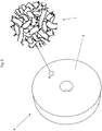
- figure 5 shows a grinding tool 4, in this case designed as a grinding wheel, which consists of a bonded abrasive body 5 using the agglomerates 1 according to the invention.
- the grinding tool or the grinding body can also have any other shape.
- the enlarged section A illustrates that 5 agglomerates 1 are embedded in the bond of the abrasive body.
Landscapes
- Chemical & Material Sciences (AREA)
- Engineering & Computer Science (AREA)
- Organic Chemistry (AREA)
- Materials Engineering (AREA)
- Inorganic Chemistry (AREA)
- Ceramic Engineering (AREA)
- Manufacturing & Machinery (AREA)
- Mechanical Engineering (AREA)
- Composite Materials (AREA)
- Structural Engineering (AREA)
- Dispersion Chemistry (AREA)
- Polishing Bodies And Polishing Tools (AREA)
Description
- Die Erfindung betrifft ein Agglomerat aus wenigstens zwei weitgehend stäbchenförmigen Schleifteilchen. Die vorliegende Erfindung betrifft auch ein Verfahren zum Herstellen eines solchen Agglomerats sowie ein Schleifwerkzeug.
- Agglomerate aus Schleifkörnern sind seit Langem bekannt und werden in vielen Variationen in gebundenen Schleifkörpern, beispielsweise Schleifscheiben, eingesetzt.
- So beschreibt beispielsweise die
EP2318468 gesinterte Schleifkornagglomerate aus Aluminiumoxid mit einem mittleren Primärteilchendurchmesser von weniger als fünf Mikrometern und einer im Wesentlichen sphärischen Außenkontur. - Der Vorteil der in der
EP2318468 geschilderten Schleifkornagglomerate besteht darin, dass feinteilige Schleifkörner als Primärteilchen eingesetzt werden können, aus denen dann ein Agglomeratkorn gebildet wird, welches im Vergleich zu einem Einzelkorn vergleichbarer Größe ein günstigeres Verschleißverhalten im Schleifprozess zeigt. Während ein Einzelkorn vergleichbarer Größe im Bearbeitungsprozess stumpf oder zerstört wird, brechen bei der Verwendung von Schleifkornagglomeraten gemäß '468 wiederholt einzelne Körnchen aus dem Verbund, sodass immer wieder neue Schleifkanten gebildet werden. So zeigt ein Schleifkörper unter Verwendung von Schleifkornagglomeraten gemäß derEP2318468 ein besseres Schliffbild sowie eine höhere Lebensdauer. In dem Verfahren zur Herstellung der Kornagglomerate gemäß derEP2318468 wird der Rohstoff mittels Nassvermahlung auf eine mittlere Teilchengröße von kleiner 5 Mikrometer, besonders bevorzugt kleiner 0,5 Mikrometer, vermahlen. Die erhaltene Dispersion wird über Sprühtrocknung getrocknet, wobei Agglomeratgrünkörper entstehen. Diese Agglomerate weisen einen Durchmesser zwischen fünf Mikrometer und 500 Mikrometer auf. Die so erhaltenen Agglomeratgrünkörper werden anschließend gesintert, wodurch die gewünschten Schleifkornagglomerate ohne den Einsatz von Bindemitteln gewonnen werden können. Die beschriebenen Kornagglomerate eignen sich aufgrund der mikroskopischen Primärkörner besonders für Feinschleifoperationen. - Die
US 3,048,482 von Hurst zeigt pyramidenförmige Schleifkörperchen, die aus einzelnen Schleifkörnern zusammengesetzt und von einem organischen Binder zusammengehalten werden. Diese Schleifkornagglomerate sind in Ausnehmungen in einer flexiblen Matrix eingebettet und dort über einen thermoplastischen Binder fixiert. - Agglomerate aus keramischen Aggregatteilchen und keramischen Schleif-Aggregatteilchen sind bereits aus der Schrift
DE 201 22 729 U1 bekannt, wobei die keramischen Aggregatteilchen in Stabform vorliegen können. - Agglomerate aus sphärischen Schleifteilchen sind bereits aus der Schrift
WO 02/38696 A1 - Gestreckte oder stäbchenförmige Schleifkörner sind beispielsweise aus der
US 3,387,957 an Howard bekannt. Howard beschreibt darin die Herstellung mikrokristalliner Schleifkörner aus Bauxit mit einem Aspektverhältnis von Länge zu Durchmesser größer als 1 und bis zu 5. Die Schrift zeigt auch die Verwendung dieser Körner in Schleifscheiben, wobei die länglichen Bauxitkörner in einer organischen Bindung eingebettet sind. - Solch stäbchenförmige oder gestreckte Schleifkörner können beispielsweise über Extrusion und anschließende Sinterung von Schleifmittel hergestellt werden und sind kommerziell verfügbar. So sind unter der Produktbezeichnung CERPASS TGE® von SAINT-GOBAIN Grains and Powders gestreckte Schleifkörner aus Korund erhältlich, die bei der sogenannten grit size von 36 eine Länge von etwa 500 Mikrometern aufweisen. Typische physikalische Eigenschaften dieses Produkts sind eine Härte von 21,60 GPa (nach Vickers Diamant), eine Dichte von 3,91 g/cm3 (Helium Pyknometrie) und eine Kristallitgröße von 0,17 µm (gemessen aus rasterelektronenmikroskopischen Aufnahmen).
- Die
EP 2 324 957 beschreibt die Herstellung und Verwendung filamentöser Sol-Gel-Aluminiumoxid -Schleifkörner. - Schleifkornagglomerate nach Stand der Technik sind aus mikroskopischen Schleifkörnern zusammengesetzte Gebilde ohne Vorzugsorientierung der individuellen Schleifkörner zueinander.
- Die Erfindung hat zur Aufgabe, verbesserte Schleifkornagglomerate sowie ein Schleifwerkzeug mit einem Schleifkörper unter Verwendung der erfindungsgemäßen Schleifkornagglomerate und ein Verfahren zur Herstellung der erfindungsgemäßen Schleifkornagglomerate und eines Schleifkörpers anzugeben. Ein weiterer Aspekt der Erfindung ist die Verbesserung der räumlichen Verteilung bzw. Orientierung von gestreckten oder stäbchenförmigen Schleifteilchen in einem Schleifkornagglomerat.
- Gelöst wird diese Aufgabe durch ein Schleifkornagglomerat nach Anspruch 1, einem Schleifwerkzeug nach Anspruch 7 sowie einem Verfahren zur Herstellung von Schleifkornagglomeraten nach Anspruch 10. Vorteilhafte Ausführungsformen sind in den Unteransprüchen angegeben.
- Das verbesserte Schleifkornagglomerat besteht aus wenigstens zwei weitgehend stäbchenförmigen Schleifteilchen, wobei die wenigstens zwei weitgehend stäbchenförmigen Schleifteilchen über eine Glasbindung miteinander verbunden sind, und die Längsachsen der wenigstens zwei stäbchenförmigen Schleifteilchen in unterschiedliche Raumrichtungen weisen. Unter Schleifteilchen wird in der Anmeldung ein abrasiver Körper verstanden, der entweder aus einem Schleifkorn besteht oder aus mehreren Schleifkörnern zusammengesetzt ist. Unter Schleifmittel ist der abrasive Werkstoff verstanden, aus dem ein Schleifkorn besteht.
- In Versuchen der Anmelderin hat sich nämlich herausgestellt, dass besonders interessante Verschleißeigenschaften erzielt werden, wenn die Schleifteilchen, aus denen das Schleifkornagglomerat zusammengesetzt ist, eine ausgeprägte Streckung aufweisen, d.h. eine stäbchenförmige Gestalt aufweisen. Unter "stäbchenförmig" sind freilich auch Abweichungen von der idealen Geometrie eines Zylinders gemeint. So können die stäbchenförmigen Schleifteilchen gekrümmt sein und / oder an ihren Enden etwa eine Nase oder eine Verdickung zeigen.
- Die wenigstens zwei stäbchenförmigen Schleifteilchen sind miteinander über eine Glasbindung verbunden. Dies kann beispielsweise so realisiert sein, dass die Schleifteilchen an ihren Berührungspunkten von erschmolzenem und wiedererstarrtem Glas benetzt und so miteinander verbunden sind. Die Verbindung befindet sich vorzugweise in der Mitte der stäbchenförmigen Schleifteilchen. Dadurch dass die Längsachsen der stäbchenförmigen Schleifteilchen in unterschiedliche Raumrichtungen weisen, ergibt sich eine äußere Gestalt, die an eine Panzersperre oder einen Igel erinnert. Diese Form von Schleifkornagglomeraten hat sich als besonders günstig hinsichtlich der Schleifeigenschaften erwiesen, denn so werden im Zuge der Abnützung immer wieder frische Schnittkanten angeboten, welche durch die Querschnitte der in unterschiedliche Raumrichtungen weisenden stäbchenförmigen Schleifteilchen gebildet sind.
- Günstigerweise besteht ein erfindungsgemäßes Schleifkornagglomerat aus einer Vielzahl von stäbchenförmigen Schleifteilchen, z.B. aus vier bis zwölf Schleifteilchen. Vorteilhaft ist es, wenn die Orientierung der stäbchenförmigen Schleifteilchen möglichst gleichmäßig in alle Raumrichtungen verteilt ist.
- Vorzugsweise kann vorgesehen sein, dass die Schleifteilchen von Schleifkörnern, bestehend aus Schleifmittel, weitgehend binderfrei dargestellt werden. Dieses Ausführungsbeispiel beschreibt den Fall, bei dem jeweils eines der stäbchenförmigen Schleifteilchen durch ein stäbchenförmiges Schleifkorn gebildet ist. Wie eingangs beschrieben, können solche Schleifteilchen durch Extrusion und anschließendes Sintern von Schleifmittel erzeugt werden.
- In einer weiteren bevorzugten Ausbildung bestehen die stäbchenförmigen Schleifteilchen aus einem Schleifmittel und einem Bindemittel. In diesem Fall sind die Schleifteilchen nicht durch ein Schleifkorn gebildet, sondern bestehen aus mehreren Primär-Schleifkörnern aus Schleifmittel, die über eine geeignete Bindung miteinander verbunden sind. Als Schleifmittel in Frage kommen alle bekannten abrasiven Werkstoffe wie etwa Korund, kubisches Bornitrid, Siliziumkarbid, Diamant.
- Zur Herstellung stäbchenförmiger Schleifteilchen werden die Primärkörner, die Abmessungen kleiner gleich des zu erzielenden Schleifteilchens aufweisen, mit einem Binder gemischt, diese Mischung formgebend verarbeitet, vorzugsweise extrudiert und anschließend auf geeignete Weise ausgehärtet.
- Das Beispiel ist nicht darauf beschränkt, dass die Schleifteilchen aus einem Schleifmittel allein und Binder bestehen. So können auch Mischungen verschiedener Schleifmittel in einem Schleifteilchen realisiert sein. Auch kann vorgesehen sein, dass ein Teil der Schleifkörner aus dem einen Schleifmittel oder einer Mischung von Schleifmitteln aufgebaut ist, und andere Schleifkörner des Agglomerats aus einem anderen Schleifmittel oder einer anderen Mischung von Schleifmitteln bestehen.
- In einer anderen bevorzugten Ausführungsform kann vorgesehen sein, dass ein Teil der Schleifteilchen von Schleifkörnern, bestehend aus Schleifmittel und weitgehend binderfrei, gebildet ist und dass der andere Teil der Schleifteilchen aus einem Schleifmittel und einem Bindemittel besteht. In anderen Worten besteht hier das Agglomerat aus einer Mischung von Schleifteilchen, welche jeweils durch ein stäbchenförmiges Schleifkorn allein gebildet sind, und anderen Schleifteilchen, welche aus mehreren Primär-Schleifkörnern aus Schleifmittel und geeigneter Bindung gebildet sind.
- Erfindungsgemäß ist die Ausprägung, dass die Schleifteilchen ein Aspektverhältnis von Länge zu Durchmesser von mindestens 2:1 aufweisen. Durch die ausgeprägte Streckung der Schleifteilchen werden besonders günstige Schleifeigenschaften erzielt. Dies ist dadurch erklärbar, dass die Schnittflächen stäbchenförmiger Teilchen weitestgehend kreisförmig oder elliptisch sind und diese Querschnittsform bei entsprechender Streckung des Teilchens während des Verschleißes für längere Zeit erhalten bleibt, wobei im Zuge der Abnützung immer wieder frische Schnittkanten gebildet werden. Dies soll anhand eines Beispiels erläutert werden: man stelle sich ein gestrecktes Schleifteilchen vor, dessen Längsachse bezüglich des Schleifwerkzeugs radial verläuft, d.h. der Vektor der Umfangsgeschwindigkeit des Schleifwerkzeuges steht normal auf die Längsachse des Schleifteilchens. Bei annähernd zylindrischer Form des Schleifteilchens bildet sich also eine kreisförmige Schnittfläche aus, die bei Abrieb des Schleifteilchens solange erhalten bleibt, bis das stäbchenförmige Schleifteilchen aufgezehrt ist.
- Im Versuch zeichnen sich Agglomerate dieser bevorzugten Ausprägung durch besonders aggressives Schleifverhalten aus und eignen sich besonders für Schleifoperationen mit hoher Kontaktzahl wie Innenrundschleifen oder Flachschleifen.
- In einer weiteren Ausführungsform ist vorgesehen, dass die Länge der Schleifteilchen wenigstens 100 Mikrometer, besonders bevorzugt rund 250 bis 800 Mikrometer beträgt.
- Die Verwendung makroskopischer Schleifteilchen, d.h. in ihrer Größenabmessung deutlich von üblicherweise verwendetem Schleifkorn abweichender Schleifteilchen hat sich als besonders vorteilhaft herausgestellt.
- Der im vorangegangenen Ausführungsbeispiel erläuterte Effekt ist nämlich besonders deutlich, wenn die Teilchen eine gewisse Mindestabmessung aufweisen. Die Wahl einer Länge der Schleifteilchen von wenigstens 100 Mikrometern, besonders bevorzugt rund 250 bis 800 Mikrometern bewirkt ein besonders aggressives Schleifverhalten bei gleichzeitig günstigem Werkzeugverschleiß.
- In Kombination mit dem Merkmal, dass die Schleifteilchen von Schleifkörnern aus Schleifmittel und weitgehend binderfrei dargestellt werden, werden besonders vorteilhafte Ergebnisse erzielt. Werden etwa Schleifteilchen aus mikrokristallinem Korund mit einer durchschnittlichen Länge von ca. 500 Mikrometern und einem Durchmesser von ca. 230 Mikrometern verwendet, sind besonders günstige Eigenschaften zu beobachten. Durch den muscheligen (conchoidalen) Bruch des mikrokristallinen Korunds weisen diese Schleifteilchen gute Selbstschärfeigenschaften auf. Die Abmessungen bewirken eine hohe absolute Festigkeit der Schleifteilchen.
- Weitere Ausführungsformen beschreiben ein Schleifwerkzeug mit einem Schleifkörper, wobei der Schleifkörper wenigstens zwei Agglomerate nach einem der vorhergehenden Beispiele aufweist, die in eine Bindungsmatrix eingebettet sind.
- Die zuvor beschriebenen Agglomerate werden über einen Binder zu einem Schleifkörper verbunden. Aus dem Schleifkörper kann ein Schleifwerkzeug, beispielsweise eine Schleifscheibe, hergestellt werden.
- In einer bevorzugten Ausführungsform ist vorgesehen, dass die Bindung des Schleifkörpers eine Kunstharzbindung ist.
- In einer alternativen Ausführungsform ist vorgesehen, dass die Bindung des Schleifkörpers eine Keramikbindung ist.
- Günstigerweise ist das Agglomerat dergestalt, dass die Schüttdichte der Agglomerate etwa 50 - 99% der Schüttdichte der Schleifteilchen als Ausgangsmaterial beträgt.
- Das Verfahren zur Herstellung eines Agglomerates umfasst die Schritte:
- Bereitstellen eines Gemisches aus wenigstens zwei stäbchenförmigen Schleifteilchen und Glaspartikeln, wobei die Glaspartikel blockig, kantig oder im Wesentlichen kugelförmig sind,
- Erhitzen des Gemisches auf eine Temperatur, die über der Schmelztemperatur der Glaspartikel und unter der Schmelztemperatur der Schleifteilchen liegt und
- Abkühlen des Gemisches auf eine Temperatur, die unterhalb der Schmelztemperatur der Glaspartikel liegt.
- Durch Aufschmelzen der Glasphase und die darauffolgende Erstarrung entstehen zwischen den Schleifteilchen feste Hälse aus Glas.
- Besonders vorteilhaft ist es, wenn der Anteil von Glaspartikeln im Gemisch von Schleifteilchen und Glaspartikeln zwischen 2 und 25 Gewichtsprozent liegt.
- In den Versuchen der Anmelderin hat sich überraschend herausgestellt, dass bei Verwendung kugelförmiger Glaspartikel, also Glasperlen, sich die räumliche Ausrichtung der stäbchenförmigen Schleifteilchen besonders günstig beeinflussen lässt. Es ist ja ein Ziel der gegenständlichen Erfindung, dass die Längsachsen der stäbchenförmigen Schleifteilchen in unterschiedliche Raumrichtungen weisen.
- Nach einer weiteren bevorzugten Ausführungsform ist vorgesehen, dass der Durchmesser der Glaspartikel im Bereich von 50 bis 1000, vorzugsweise zwischen 150 bis 250 Mikrometer liegt.
- In einem Versuch wurden stäbchenförmige Schleifteilchen mit einem Durchmesser von ca. 100 Mikrometern (CERPASS TGE® 120 grit) mit Glasperlen einer Fraktion von 150-250 Mikrometern gemischt. Das Gewichtsverhältnis von Korn zu Kugeln betrug dabei 100:5. Die nach dem Verfahren hergestellten Agglomerate weisen eine besonders gleichmäßige Verteilung der Orientierung der Körner in alle Raumrichtungen auf, in anderen Worten entsteht ein Agglomerat mit möglichst wenigen parallel zueinander liegenden Körnern.
- Die Erfindung wird weiter durch die Figuren veranschaulicht. Dabei zeigen:
- Fig. 1
- eine schematische Darstellung eines Kornagglomerates,
- Fig. 2
- eine schematische Darstellung einzelner Primärkörner,
- Fig. 3
- eine lichtmikroskopische Aufnahme einiger Kornagglomerate,
- Fig. 4
- ein Flussdiagramm des Herstellungsprozesses,
- Fig. 5
- ein Schleifwerkzeug, hier eine Schleifscheibe unter Verwendung der erfindungsgemäßen Agglomerate
-
Figur 1 zeigt schematisch ein Schleifkornagglomerat 1 aus mehreren stäbchenförmigen Schleifteilchen 2. Die einzelnen Schleifteilchen 2 sind über eine Glasbindung 3 miteinander verbunden. Die Glasbindung 3 ist in Form von Hälsen zwischen den stäbchenförmigen Schleifteilchen 2 ausgebildet. -
Figur 2 zeigt einzelne gestreckte Schleifteilchen 2. - In
Figur 3 sind in einer lichtmikroskopischen Aufnahme einige Schleifkornagglomerate 1 zu sehen. Es ist gut erkennbar, dass die stäbchenförmigen Schleifteilchen 2 in unterschiedliche Raumrichtungen weisen. -
Figur 4 illustriert schematisch den Herstellungsprozess zur Gewinnung von Schleifkornagglomeraten 1. -
Figur 5 zeigt ein Schleifwerkzeug 4, in diesem Fall als Schleifscheibe ausgebildet, das aus einem gebundenen Schleifkörper 5 unter Verwendung der erfindungsgemäßen Agglomerate 1 besteht. Das Schleifwerkzeug bzw. der Schleifkörper können natürlich auch beliebig andere Formen aufweisen. - Durch den vergrößerten Ausschnitt A wird illustriert, dass in die Bindung des Schleifkörpers 5 Agglomerate 1 eingebettet sind.
- Liste der verwendeten Bezugszeichen:
- 1
- Schleifkornagglomerat
- 2
- Schleifteilchen
- 3
- Glasbindung
- 4
- Schleifwerkzeug
Claims (12)
- Agglomerat (1) aus wenigstens zwei weitgehend stäbchenförmigen Schleifteilchen (2), dadurch gekennzeichnet, dass die wenigstens zwei der weitgehend stäbchenförmigen Schleifteilchen (2) über eine Glasbindung (3) miteinander verbunden sind, wobei die Längsachsen der wenigstens zwei stäbchenförmigen Schleifteilchen (2) in unterschiedliche Raumrichtungen weisen, wobei die Schleifteilchen (2) ein Aspektverhältnis von Länge zu Durchmesser von mindestens 2:1 aufweisen.
- Agglomerat (1) gemäß Anspruch 1, dadurch gekennzeichnet, dass die Schleifteilchen (2) von Schleifkörnern, bestehend aus Schleifmittel, weitgehend binderfrei dargestellt werden.
- Agglomerat (1) nach Anspruch 1, dadurch gekennzeichnet, dass die Schleifteilchen (2) aus wenigstens einem Schleifmittel und einem Bindemittel bestehen.
- Agglomerat (1) nach Anspruch 1, dadurch gekennzeichnet, dass ein Teil der Schleifteilchen (2) von Schleifkörnern, bestehend aus Schleifmittel und weitgehend binderfrei, gebildet ist und dass der andere Teil der Schleifteilchen (2) aus einem Schleifmittel und einem Bindemittel besteht.
- Agglomerat (1) nach wenigstens einem der vorangegangenen Ansprüche, dadurch gekennzeichnet, dass die Länge der Schleifteilchen (2) wenigstens 100 Mikrometer, besonders bevorzugt rund 250 bis 800 Mikrometer beträgt.
- Agglomerat (1) nach wenigstens einem der vorangegangenen Ansprüche, dadurch gekennzeichnet, dass die Schüttdichte des Agglomerats (1) etwa 50 - 99% der Schüttdichte der Schleifteilchen (2) beträgt.
- Schleifwerkzeug (4) mit einem Schleifkörper (5), dadurch gekennzeichnet, dass der Schleifkörper (5) wenigstens zwei Agglomerate (1) nach wenigstens einem der vorangegangenen Ansprüche aufweist, die in eine Bindungsmatrix eingebettet sind.
- Schleifwerkzeug (4) nach Anspruch 7, dadurch gekennzeichnet, dass die Bindung eine Kunstharzbindung ist.
- Schleifwerkzeug (4) nach Anspruch 7, dadurch gekennzeichnet, dass die Bindung eine Keramikbindung ist.
- Verfahren zur Herstellung eines Agglomerates (1) nach wenigstens einem der Ansprüche 1 bis 6, umfassend die folgenden Verfahrensschritte:- Bereitstellen eines Gemisches aus wenigstens zwei stäbchenförmigen Schleifteilchen (2) und Glaspartikeln, wobei die Glaspartikel blockig, kantig oder im Wesentlichen kugelförmig sind,- Erhitzen des Gemisches auf eine Temperatur, die über der Schmelztemperatur der Glaspartikel und unter der Schmelztemperatur der Schleifteilchen (2) liegt und- Abkühlen des Gemisches auf eine Temperatur, die unterhalb der Schmelztemperatur der Glaspartikel liegt.
- Verfahren nach Anspruch 10, dadurch gekennzeichnet, dass der Anteil von Glaspartikeln im Gemisch von Schleifteilchen (2) und Glaspartikeln zwischen 2 und 25 Gewichtsprozent liegt.
- Verfahren nach Anspruch 10 oder 11, dadurch gekennzeichnet, dass der Durchmesser der Glaspartikel im Bereich von 50 bis 1000, vorzugsweise zwischen 100 bis 500 Mikrometer liegt.
Priority Applications (2)
| Application Number | Priority Date | Filing Date | Title |
|---|---|---|---|
| EP21216300.0A EP3992263A1 (de) | 2014-03-25 | 2015-03-09 | Schleifteilchenagglomerat |
| SI201531855T SI3122835T1 (sl) | 2014-03-25 | 2015-03-09 | Aglomerat brusilnih delcev |
Applications Claiming Priority (2)
| Application Number | Priority Date | Filing Date | Title |
|---|---|---|---|
| ATA212/2014A AT515587B1 (de) | 2014-03-25 | 2014-03-25 | Schleifteilchenagglomerat |
| PCT/AT2015/000034 WO2015143461A1 (de) | 2014-03-25 | 2015-03-09 | Schleifteilchenagglomerat |
Related Child Applications (2)
| Application Number | Title | Priority Date | Filing Date |
|---|---|---|---|
| EP21216300.0A Division-Into EP3992263A1 (de) | 2014-03-25 | 2015-03-09 | Schleifteilchenagglomerat |
| EP21216300.0A Division EP3992263A1 (de) | 2014-03-25 | 2015-03-09 | Schleifteilchenagglomerat |
Publications (2)
| Publication Number | Publication Date |
|---|---|
| EP3122835A1 EP3122835A1 (de) | 2017-02-01 |
| EP3122835B1 true EP3122835B1 (de) | 2022-04-27 |
Family
ID=52828930
Family Applications (2)
| Application Number | Title | Priority Date | Filing Date |
|---|---|---|---|
| EP15715956.7A Active EP3122835B1 (de) | 2014-03-25 | 2015-03-09 | Schleifteilchenagglomerat |
| EP21216300.0A Pending EP3992263A1 (de) | 2014-03-25 | 2015-03-09 | Schleifteilchenagglomerat |
Family Applications After (1)
| Application Number | Title | Priority Date | Filing Date |
|---|---|---|---|
| EP21216300.0A Pending EP3992263A1 (de) | 2014-03-25 | 2015-03-09 | Schleifteilchenagglomerat |
Country Status (8)
| Country | Link |
|---|---|
| EP (2) | EP3122835B1 (de) |
| AT (1) | AT515587B1 (de) |
| DK (1) | DK3122835T3 (de) |
| ES (1) | ES2921802T3 (de) |
| HU (1) | HUE059335T2 (de) |
| PL (1) | PL3122835T3 (de) |
| SI (1) | SI3122835T1 (de) |
| WO (1) | WO2015143461A1 (de) |
Families Citing this family (19)
| Publication number | Priority date | Publication date | Assignee | Title |
|---|---|---|---|---|
| KR101667943B1 (ko) | 2012-01-10 | 2016-10-20 | 생-고뱅 세라믹스 앤드 플라스틱스, 인코포레이티드 | 복잡한 형상들을 가지는 연마 입자들 및 이의 성형 방법들 |
| PL2852473T3 (pl) | 2012-05-23 | 2021-06-28 | Saint-Gobain Ceramics & Plastics Inc. | Ukształtowane cząstki ścierne i sposoby ich formowania |
| BR112015024901B1 (pt) | 2013-03-29 | 2022-01-18 | Saint-Gobain Abrasifs | Partículas abrasivas tendo formas particulares e métodos para formar essas partículas |
| MX2016004000A (es) | 2013-09-30 | 2016-06-02 | Saint Gobain Ceramics | Particulas abrasivas moldeadas y metodos para formación de ellas. |
| JP6290428B2 (ja) | 2013-12-31 | 2018-03-07 | サンーゴバン アブレイシブズ,インコーポレイティド | 成形研磨粒子を含む研磨物品 |
| US9771507B2 (en) | 2014-01-31 | 2017-09-26 | Saint-Gobain Ceramics & Plastics, Inc. | Shaped abrasive particle including dopant material and method of forming same |
| MX394114B (es) | 2014-04-14 | 2025-03-24 | Saint Gobain Ceramics | Articulo abrasivo que incluye particulas abrasivas conformadas. |
| US9914864B2 (en) | 2014-12-23 | 2018-03-13 | Saint-Gobain Ceramics & Plastics, Inc. | Shaped abrasive particles and method of forming same |
| TWI634200B (zh) | 2015-03-31 | 2018-09-01 | 聖高拜磨料有限公司 | 固定磨料物品及其形成方法 |
| CN107636109A (zh) | 2015-03-31 | 2018-01-26 | 圣戈班磨料磨具有限公司 | 固定磨料制品和其形成方法 |
| WO2016201104A1 (en) | 2015-06-11 | 2016-12-15 | Saint-Gobain Ceramics & Plastics, Inc. | Abrasive article including shaped abrasive particles |
| WO2017197006A1 (en) | 2016-05-10 | 2017-11-16 | Saint-Gobain Ceramics & Plastics, Inc. | Abrasive particles and methods of forming same |
| US20170335155A1 (en) | 2016-05-10 | 2017-11-23 | Saint-Gobain Ceramics & Plastics, Inc. | Abrasive particles and methods of forming same |
| US10563105B2 (en) | 2017-01-31 | 2020-02-18 | Saint-Gobain Ceramics & Plastics, Inc. | Abrasive article including shaped abrasive particles |
| US12129422B2 (en) | 2019-12-27 | 2024-10-29 | Saint-Gobain Ceramics & Plastics, Inc. | Abrasive articles and methods of forming same |
| EP4081370A4 (de) | 2019-12-27 | 2024-04-24 | Saint-Gobain Ceramics & Plastics Inc. | Schleifartikel und verfahren zur formung davon |
| EP4081369A4 (de) | 2019-12-27 | 2024-04-10 | Saint-Gobain Ceramics & Plastics Inc. | Schleifartikel und verfahren zur formung davon |
| CN118541241A (zh) | 2021-12-30 | 2024-08-23 | 圣戈班磨料磨具有限公司 | 磨料制品及其形成方法 |
| MX2024007593A (es) | 2021-12-30 | 2024-08-20 | Saint Gobain Abrasives Inc | Artículos abrasivos y métodos de formación de los mismos. |
Family Cites Families (15)
| Publication number | Priority date | Publication date | Assignee | Title |
|---|---|---|---|---|
| US3048482A (en) | 1958-10-22 | 1962-08-07 | Rexall Drug Co | Abrasive articles and methods of making the same |
| US3387957A (en) | 1966-04-04 | 1968-06-11 | Carborundum Co | Microcrystalline sintered bauxite abrasive grain |
| US5738696A (en) * | 1996-07-26 | 1998-04-14 | Norton Company | Method for making high permeability grinding wheels |
| DE20122729U1 (de) * | 2000-10-06 | 2007-06-06 | 3M Innovative Properties Co., St. Paul | Keramische Aggregatteilchen |
| EP1770143A3 (de) * | 2000-10-06 | 2008-05-07 | 3M Innovative Properties Company | Agglomeriertes Schleifmittelkorn und Verfahren zu seiner Herstellung |
| WO2002032832A1 (en) * | 2000-10-16 | 2002-04-25 | 3M Innovative Properties Company | Method of making abrasive agglomerate particles and abrasive articles therefrom |
| US6551366B1 (en) * | 2000-11-10 | 2003-04-22 | 3M Innovative Properties Company | Spray drying methods of making agglomerate abrasive grains and abrasive articles |
| US6679758B2 (en) * | 2002-04-11 | 2004-01-20 | Saint-Gobain Abrasives Technology Company | Porous abrasive articles with agglomerated abrasives |
| US7090565B2 (en) * | 2002-04-11 | 2006-08-15 | Saint-Gobain Abrasives Technology Company | Method of centerless grinding |
| US6797023B2 (en) * | 2002-05-14 | 2004-09-28 | Saint-Gobain Abrasives Technology Company | Coated abrasives |
| US7722691B2 (en) | 2005-09-30 | 2010-05-25 | Saint-Gobain Abrasives, Inc. | Abrasive tools having a permeable structure |
| DE102008035515B3 (de) | 2008-07-30 | 2009-12-31 | Center For Abrasives And Refractories Research & Development C.A.R.R.D. Gmbh | Gesinterte Schleifkornagglomerate |
| PL2174751T3 (pl) * | 2008-10-10 | 2014-12-31 | Center For Abrasives And Refractories Res & Development C A R R D Gmbh | Aglomeraty ziaren ściernych, sposób ich wytwarzania, jak również ich zastosowanie do produkcji materiałów ściernych |
| WO2013003814A2 (en) * | 2011-06-30 | 2013-01-03 | Saint-Gobain Ceramics & Plastics, Inc. | An abrasive aggregate including silicon carbide and a method of making same |
| US20130000210A1 (en) * | 2011-06-30 | 2013-01-03 | Saint-Gobain Ceramics & Plastics, Inc. | Abrasive segment comprising abrasive aggregates including silicon carbide particles |
-
2014
- 2014-03-25 AT ATA212/2014A patent/AT515587B1/de active
-
2015
- 2015-03-09 HU HUE15715956A patent/HUE059335T2/hu unknown
- 2015-03-09 EP EP15715956.7A patent/EP3122835B1/de active Active
- 2015-03-09 EP EP21216300.0A patent/EP3992263A1/de active Pending
- 2015-03-09 SI SI201531855T patent/SI3122835T1/sl unknown
- 2015-03-09 PL PL15715956.7T patent/PL3122835T3/pl unknown
- 2015-03-09 WO PCT/AT2015/000034 patent/WO2015143461A1/de not_active Ceased
- 2015-03-09 ES ES15715956T patent/ES2921802T3/es active Active
- 2015-03-09 DK DK15715956.7T patent/DK3122835T3/da active
Also Published As
| Publication number | Publication date |
|---|---|
| AT515587A1 (de) | 2015-10-15 |
| AT515587B1 (de) | 2017-05-15 |
| HUE059335T2 (hu) | 2022-11-28 |
| ES2921802T3 (es) | 2022-08-31 |
| DK3122835T3 (da) | 2022-08-01 |
| WO2015143461A1 (de) | 2015-10-01 |
| PL3122835T3 (pl) | 2022-08-22 |
| SI3122835T1 (sl) | 2022-08-31 |
| EP3122835A1 (de) | 2017-02-01 |
| EP3992263A1 (de) | 2022-05-04 |
Similar Documents
| Publication | Publication Date | Title |
|---|---|---|
| EP3122835B1 (de) | Schleifteilchenagglomerat | |
| EP3645653B1 (de) | Geformtes keramisches schleifkorn | |
| EP2941354B1 (de) | Schleifpartikel und schleifmittel mit hoher schleifleistung | |
| DE69515180T2 (de) | Schlufprodukt | |
| EP3083869B1 (de) | Verfahren zur herstellung von schleifkörpern | |
| DE202014101739U1 (de) | Schleifkorn mit Knoten und Fortsätzen | |
| DE102018212732A1 (de) | Geformtes keramisches Schleifkorn, Verfahren zur Herstellung eines geformten keramischen Schleifkorns und Schleifartikel | |
| EP2938691B1 (de) | Schleifkorn mit höchstens drei flächen und einer ecke | |
| EP2692813A1 (de) | Schleifkorn mit Erhebungen verschiedener Höhen | |
| EP2692820A1 (de) | Schleifkorn mit Basiskörper, Erhebung und Öffnung | |
| DE102013212644A1 (de) | Verfahren zur Herstellung eines Schleifmittels | |
| EP2692816A1 (de) | Schleifkorn mit einander durchdringenden flächigen Körpern | |
| DD297994A5 (de) | Schleifmittelprodukte | |
| DE202014101741U1 (de) | Teilweise beschichtetes Schleifkorn | |
| EP2692819A1 (de) | Schleifkorn mit Basisfläche und Erhebungen | |
| EP2692821A1 (de) | Schleifkorn mit Basiskörper und Aufsatzkörper | |
| EP0826758B1 (de) | Verbundschneidkörper enthaltend Diamantpartikel und Verfahren zu deren Herstellung | |
| EP3704073B1 (de) | Verfahren zum herstellen eines baustoffgranulats auf basis von mineralkörnern | |
| DE19805889C2 (de) | Sinterkörper auf der Basis von Korund mit einer geschlossenen Zellstruktur, dessen Herstellung und Verwendung | |
| AT506893B1 (de) | Zweifärbiges keramikformteil | |
| DE102013111006B4 (de) | Polykristalline poröse Al2O3-Körper auf Basis von geschmolzenem Aluminiumoxid mit erhöhter Zähigkeit | |
| DE112019001807T5 (de) | Hochporöser, keramisch gebundener CBN-Schleifstein homogenen Aufbaus | |
| DE102010006250A1 (de) | Schleifkörper und Verfahren zur Herstellung hiervon | |
| EP3360944A2 (de) | Schleifmittel | |
| AT360363B (de) | Harzgebundene schleifkoerper mit synthetischen rd-diamantteilchen |
Legal Events
| Date | Code | Title | Description |
|---|---|---|---|
| STAA | Information on the status of an ep patent application or granted ep patent |
Free format text: STATUS: THE INTERNATIONAL PUBLICATION HAS BEEN MADE |
|
| PUAI | Public reference made under article 153(3) epc to a published international application that has entered the european phase |
Free format text: ORIGINAL CODE: 0009012 |
|
| STAA | Information on the status of an ep patent application or granted ep patent |
Free format text: STATUS: REQUEST FOR EXAMINATION WAS MADE |
|
| 17P | Request for examination filed |
Effective date: 20161017 |
|
| AK | Designated contracting states |
Kind code of ref document: A1 Designated state(s): AL AT BE BG CH CY CZ DE DK EE ES FI FR GB GR HR HU IE IS IT LI LT LU LV MC MK MT NL NO PL PT RO RS SE SI SK SM TR |
|
| AX | Request for extension of the european patent |
Extension state: BA ME |
|
| DAV | Request for validation of the european patent (deleted) | ||
| DAX | Request for extension of the european patent (deleted) | ||
| STAA | Information on the status of an ep patent application or granted ep patent |
Free format text: STATUS: EXAMINATION IS IN PROGRESS |
|
| 17Q | First examination report despatched |
Effective date: 20191212 |
|
| GRAP | Despatch of communication of intention to grant a patent |
Free format text: ORIGINAL CODE: EPIDOSNIGR1 |
|
| STAA | Information on the status of an ep patent application or granted ep patent |
Free format text: STATUS: GRANT OF PATENT IS INTENDED |
|
| INTG | Intention to grant announced |
Effective date: 20211115 |
|
| GRAS | Grant fee paid |
Free format text: ORIGINAL CODE: EPIDOSNIGR3 |
|
| GRAA | (expected) grant |
Free format text: ORIGINAL CODE: 0009210 |
|
| STAA | Information on the status of an ep patent application or granted ep patent |
Free format text: STATUS: THE PATENT HAS BEEN GRANTED |
|
| RIN1 | Information on inventor provided before grant (corrected) |
Inventor name: HIRSCHMANN, MARTIN |
|
| AK | Designated contracting states |
Kind code of ref document: B1 Designated state(s): AL AT BE BG CH CY CZ DE DK EE ES FI FR GB GR HR HU IE IS IT LI LT LU LV MC MK MT NL NO PL PT RO RS SE SI SK SM TR |
|
| REG | Reference to a national code |
Ref country code: GB Ref legal event code: FG4D Free format text: NOT ENGLISH |
|
| REG | Reference to a national code |
Ref country code: CH Ref legal event code: EP |
|
| REG | Reference to a national code |
Ref country code: DE Ref legal event code: R096 Ref document number: 502015015801 Country of ref document: DE |
|
| REG | Reference to a national code |
Ref country code: AT Ref legal event code: REF Ref document number: 1486944 Country of ref document: AT Kind code of ref document: T Effective date: 20220515 |
|
| REG | Reference to a national code |
Ref country code: IE Ref legal event code: FG4D Free format text: LANGUAGE OF EP DOCUMENT: GERMAN |
|
| REG | Reference to a national code |
Ref country code: FI Ref legal event code: FGE |
|
| REG | Reference to a national code |
Ref country code: DK Ref legal event code: T3 Effective date: 20220726 |
|
| REG | Reference to a national code |
Ref country code: NL Ref legal event code: FP |
|
| REG | Reference to a national code |
Ref country code: SE Ref legal event code: TRGR |
|
| REG | Reference to a national code |
Ref country code: LT Ref legal event code: MG9D |
|
| REG | Reference to a national code |
Ref country code: ES Ref legal event code: FG2A Ref document number: 2921802 Country of ref document: ES Kind code of ref document: T3 Effective date: 20220831 |
|
| PG25 | Lapsed in a contracting state [announced via postgrant information from national office to epo] |
Ref country code: PT Free format text: LAPSE BECAUSE OF FAILURE TO SUBMIT A TRANSLATION OF THE DESCRIPTION OR TO PAY THE FEE WITHIN THE PRESCRIBED TIME-LIMIT Effective date: 20220829 Ref country code: NO Free format text: LAPSE BECAUSE OF FAILURE TO SUBMIT A TRANSLATION OF THE DESCRIPTION OR TO PAY THE FEE WITHIN THE PRESCRIBED TIME-LIMIT Effective date: 20220727 Ref country code: LT Free format text: LAPSE BECAUSE OF FAILURE TO SUBMIT A TRANSLATION OF THE DESCRIPTION OR TO PAY THE FEE WITHIN THE PRESCRIBED TIME-LIMIT Effective date: 20220427 Ref country code: HR Free format text: LAPSE BECAUSE OF FAILURE TO SUBMIT A TRANSLATION OF THE DESCRIPTION OR TO PAY THE FEE WITHIN THE PRESCRIBED TIME-LIMIT Effective date: 20220427 Ref country code: GR Free format text: LAPSE BECAUSE OF FAILURE TO SUBMIT A TRANSLATION OF THE DESCRIPTION OR TO PAY THE FEE WITHIN THE PRESCRIBED TIME-LIMIT Effective date: 20220728 Ref country code: BG Free format text: LAPSE BECAUSE OF FAILURE TO SUBMIT A TRANSLATION OF THE DESCRIPTION OR TO PAY THE FEE WITHIN THE PRESCRIBED TIME-LIMIT Effective date: 20220727 |
|
| REG | Reference to a national code |
Ref country code: HU Ref legal event code: AG4A Ref document number: E059335 Country of ref document: HU |
|
| PG25 | Lapsed in a contracting state [announced via postgrant information from national office to epo] |
Ref country code: RS Free format text: LAPSE BECAUSE OF FAILURE TO SUBMIT A TRANSLATION OF THE DESCRIPTION OR TO PAY THE FEE WITHIN THE PRESCRIBED TIME-LIMIT Effective date: 20220427 Ref country code: LV Free format text: LAPSE BECAUSE OF FAILURE TO SUBMIT A TRANSLATION OF THE DESCRIPTION OR TO PAY THE FEE WITHIN THE PRESCRIBED TIME-LIMIT Effective date: 20220427 Ref country code: IS Free format text: LAPSE BECAUSE OF FAILURE TO SUBMIT A TRANSLATION OF THE DESCRIPTION OR TO PAY THE FEE WITHIN THE PRESCRIBED TIME-LIMIT Effective date: 20220827 |
|
| REG | Reference to a national code |
Ref country code: DE Ref legal event code: R097 Ref document number: 502015015801 Country of ref document: DE |
|
| PG25 | Lapsed in a contracting state [announced via postgrant information from national office to epo] |
Ref country code: SM Free format text: LAPSE BECAUSE OF FAILURE TO SUBMIT A TRANSLATION OF THE DESCRIPTION OR TO PAY THE FEE WITHIN THE PRESCRIBED TIME-LIMIT Effective date: 20220427 Ref country code: RO Free format text: LAPSE BECAUSE OF FAILURE TO SUBMIT A TRANSLATION OF THE DESCRIPTION OR TO PAY THE FEE WITHIN THE PRESCRIBED TIME-LIMIT Effective date: 20220427 Ref country code: EE Free format text: LAPSE BECAUSE OF FAILURE TO SUBMIT A TRANSLATION OF THE DESCRIPTION OR TO PAY THE FEE WITHIN THE PRESCRIBED TIME-LIMIT Effective date: 20220427 |
|
| PLBE | No opposition filed within time limit |
Free format text: ORIGINAL CODE: 0009261 |
|
| STAA | Information on the status of an ep patent application or granted ep patent |
Free format text: STATUS: NO OPPOSITION FILED WITHIN TIME LIMIT |
|
| PG25 | Lapsed in a contracting state [announced via postgrant information from national office to epo] |
Ref country code: AL Free format text: LAPSE BECAUSE OF FAILURE TO SUBMIT A TRANSLATION OF THE DESCRIPTION OR TO PAY THE FEE WITHIN THE PRESCRIBED TIME-LIMIT Effective date: 20220427 |
|
| 26N | No opposition filed |
Effective date: 20230130 |
|
| PG25 | Lapsed in a contracting state [announced via postgrant information from national office to epo] |
Ref country code: MC Free format text: LAPSE BECAUSE OF FAILURE TO SUBMIT A TRANSLATION OF THE DESCRIPTION OR TO PAY THE FEE WITHIN THE PRESCRIBED TIME-LIMIT Effective date: 20220427 |
|
| PG25 | Lapsed in a contracting state [announced via postgrant information from national office to epo] |
Ref country code: LU Free format text: LAPSE BECAUSE OF NON-PAYMENT OF DUE FEES Effective date: 20230309 |
|
| REG | Reference to a national code |
Ref country code: IE Ref legal event code: MM4A |
|
| PG25 | Lapsed in a contracting state [announced via postgrant information from national office to epo] |
Ref country code: IE Free format text: LAPSE BECAUSE OF NON-PAYMENT OF DUE FEES Effective date: 20230309 |
|
| PG25 | Lapsed in a contracting state [announced via postgrant information from national office to epo] |
Ref country code: BG Free format text: LAPSE BECAUSE OF FAILURE TO SUBMIT A TRANSLATION OF THE DESCRIPTION OR TO PAY THE FEE WITHIN THE PRESCRIBED TIME-LIMIT Effective date: 20220427 |
|
| PG25 | Lapsed in a contracting state [announced via postgrant information from national office to epo] |
Ref country code: BG Free format text: LAPSE BECAUSE OF FAILURE TO SUBMIT A TRANSLATION OF THE DESCRIPTION OR TO PAY THE FEE WITHIN THE PRESCRIBED TIME-LIMIT Effective date: 20220427 |
|
| PGFP | Annual fee paid to national office [announced via postgrant information from national office to epo] |
Ref country code: NL Payment date: 20250226 Year of fee payment: 11 |
|
| PGFP | Annual fee paid to national office [announced via postgrant information from national office to epo] |
Ref country code: DE Payment date: 20250327 Year of fee payment: 11 |
|
| PGFP | Annual fee paid to national office [announced via postgrant information from national office to epo] |
Ref country code: DK Payment date: 20250326 Year of fee payment: 11 Ref country code: FI Payment date: 20250318 Year of fee payment: 11 |
|
| PGFP | Annual fee paid to national office [announced via postgrant information from national office to epo] |
Ref country code: HU Payment date: 20250312 Year of fee payment: 11 |
|
| PGFP | Annual fee paid to national office [announced via postgrant information from national office to epo] |
Ref country code: SE Payment date: 20250228 Year of fee payment: 11 |
|
| PGFP | Annual fee paid to national office [announced via postgrant information from national office to epo] |
Ref country code: AT Payment date: 20250325 Year of fee payment: 11 Ref country code: SI Payment date: 20250221 Year of fee payment: 11 Ref country code: BE Payment date: 20250226 Year of fee payment: 11 |
|
| PGFP | Annual fee paid to national office [announced via postgrant information from national office to epo] |
Ref country code: FR Payment date: 20250221 Year of fee payment: 11 Ref country code: PL Payment date: 20250224 Year of fee payment: 11 Ref country code: CZ Payment date: 20250226 Year of fee payment: 11 |
|
| PGFP | Annual fee paid to national office [announced via postgrant information from national office to epo] |
Ref country code: IT Payment date: 20250306 Year of fee payment: 11 Ref country code: SK Payment date: 20250225 Year of fee payment: 11 Ref country code: GB Payment date: 20250224 Year of fee payment: 11 |
|
| PGFP | Annual fee paid to national office [announced via postgrant information from national office to epo] |
Ref country code: TR Payment date: 20250310 Year of fee payment: 11 |
|
| PGFP | Annual fee paid to national office [announced via postgrant information from national office to epo] |
Ref country code: ES Payment date: 20250402 Year of fee payment: 11 |
|
| PGFP | Annual fee paid to national office [announced via postgrant information from national office to epo] |
Ref country code: CH Payment date: 20250401 Year of fee payment: 11 |
|
| PG25 | Lapsed in a contracting state [announced via postgrant information from national office to epo] |
Ref country code: CY Free format text: LAPSE BECAUSE OF FAILURE TO SUBMIT A TRANSLATION OF THE DESCRIPTION OR TO PAY THE FEE WITHIN THE PRESCRIBED TIME-LIMIT; INVALID AB INITIO Effective date: 20150309 |