EP3122720B1 - Verfahren zum betreiben einer gasphasenphosgenierungsanlage - Google Patents
Verfahren zum betreiben einer gasphasenphosgenierungsanlage Download PDFInfo
- Publication number
- EP3122720B1 EP3122720B1 EP15711761.5A EP15711761A EP3122720B1 EP 3122720 B1 EP3122720 B1 EP 3122720B1 EP 15711761 A EP15711761 A EP 15711761A EP 3122720 B1 EP3122720 B1 EP 3122720B1
- Authority
- EP
- European Patent Office
- Prior art keywords
- phosgene
- zone
- reaction
- amine
- gas phase
- Prior art date
- Legal status (The legal status is an assumption and is not a legal conclusion. Google has not performed a legal analysis and makes no representation as to the accuracy of the status listed.)
- Active
Links
Images

Classifications
-
- C—CHEMISTRY; METALLURGY
- C07—ORGANIC CHEMISTRY
- C07C—ACYCLIC OR CARBOCYCLIC COMPOUNDS
- C07C263/00—Preparation of derivatives of isocyanic acid
- C07C263/10—Preparation of derivatives of isocyanic acid by reaction of amines with carbonyl halides, e.g. with phosgene
-
- B—PERFORMING OPERATIONS; TRANSPORTING
- B01—PHYSICAL OR CHEMICAL PROCESSES OR APPARATUS IN GENERAL
- B01J—CHEMICAL OR PHYSICAL PROCESSES, e.g. CATALYSIS OR COLLOID CHEMISTRY; THEIR RELEVANT APPARATUS
- B01J19/00—Chemical, physical or physico-chemical processes in general; Their relevant apparatus
- B01J19/0006—Controlling or regulating processes
-
- B—PERFORMING OPERATIONS; TRANSPORTING
- B01—PHYSICAL OR CHEMICAL PROCESSES OR APPARATUS IN GENERAL
- B01J—CHEMICAL OR PHYSICAL PROCESSES, e.g. CATALYSIS OR COLLOID CHEMISTRY; THEIR RELEVANT APPARATUS
- B01J19/00—Chemical, physical or physico-chemical processes in general; Their relevant apparatus
- B01J19/24—Stationary reactors without moving elements inside
-
- C—CHEMISTRY; METALLURGY
- C07—ORGANIC CHEMISTRY
- C07C—ACYCLIC OR CARBOCYCLIC COMPOUNDS
- C07C263/00—Preparation of derivatives of isocyanic acid
- C07C263/18—Separation; Purification; Stabilisation; Use of additives
- C07C263/20—Separation; Purification
-
- C—CHEMISTRY; METALLURGY
- C07—ORGANIC CHEMISTRY
- C07C—ACYCLIC OR CARBOCYCLIC COMPOUNDS
- C07C265/00—Derivatives of isocyanic acid
- C07C265/14—Derivatives of isocyanic acid containing at least two isocyanate groups bound to the same carbon skeleton
-
- B—PERFORMING OPERATIONS; TRANSPORTING
- B01—PHYSICAL OR CHEMICAL PROCESSES OR APPARATUS IN GENERAL
- B01J—CHEMICAL OR PHYSICAL PROCESSES, e.g. CATALYSIS OR COLLOID CHEMISTRY; THEIR RELEVANT APPARATUS
- B01J2219/00—Chemical, physical or physico-chemical processes in general; Their relevant apparatus
- B01J2219/00002—Chemical plants
- B01J2219/00027—Process aspects
-
- B—PERFORMING OPERATIONS; TRANSPORTING
- B01—PHYSICAL OR CHEMICAL PROCESSES OR APPARATUS IN GENERAL
- B01J—CHEMICAL OR PHYSICAL PROCESSES, e.g. CATALYSIS OR COLLOID CHEMISTRY; THEIR RELEVANT APPARATUS
- B01J2219/00—Chemical, physical or physico-chemical processes in general; Their relevant apparatus
- B01J2219/00049—Controlling or regulating processes
- B01J2219/00164—Controlling or regulating processes controlling the flow
-
- B—PERFORMING OPERATIONS; TRANSPORTING
- B01—PHYSICAL OR CHEMICAL PROCESSES OR APPARATUS IN GENERAL
- B01J—CHEMICAL OR PHYSICAL PROCESSES, e.g. CATALYSIS OR COLLOID CHEMISTRY; THEIR RELEVANT APPARATUS
- B01J2219/00—Chemical, physical or physico-chemical processes in general; Their relevant apparatus
- B01J2219/24—Stationary reactors without moving elements inside
Definitions
- the invention relates to a method for operating a gas phase phosgenation plant ( 100 ) for reacting an amine ( 2 ) with phosgene ( 1 ) to the corresponding isocyanate ( 4 ), in which the amine stream is shut off and the phosgene stream is maintained for decommissioning the gas phase phosgenation plant ( 100 ) ,
- a period which is 10 times, preferably 30 times, more preferably 60 times, most preferably 90 times
- the residence time of phosgene ( 1 ) in the essential parts of the gas phase phosgenation plant ( 100 ) during normal operation thereof from the time when the amine feed was completely shut off the phosgene supply is also turned off.
- an inert gas stream ( 30 ) is maintained during decommissioning.
- Isocyanates are produced in large quantities and serve mainly as starting materials for the production of polyurethanes. They are usually prepared by reacting the corresponding amines with phosgene, wherein phosgene is used in stoichiometric excess. The reaction of the amines with the phosgene can be carried out both in the gas phase and in the liquid phase.
- the procedure in the gas phase commonly referred to as gas phase phosgenation, is characterized in that the reaction conditions are chosen so that at least the reaction components amine, isocyanate and phosgene, but preferably all starting materials, products and reaction intermediates, are gaseous at the selected conditions.
- Advantages of gas phase phosgenation include u. a.
- the present invention relates exclusively to gas phase phosgenation and more particularly relates to a smooth process for starting up a gas phase phosgenation plant.
- EP-A-0 289 840 describes the preparation of diisocyanates by gas phase phosgenation, wherein the preparation according to the invention takes place in a turbulent flow at temperatures between 200 ° C and 600 ° C in a cylindrical space without moving parts.
- EP-A-0 570 799 relates to a process for the preparation of aromatic diisocyanates, in which the reaction of the associated diamine with the phosgene in a tubular reactor above the boiling temperature of the diamine is carried out within a mean contact time of 0.5 to 5 seconds.
- EP-A-0 699 657 describes a process for the preparation of aromatic diisocyanates in the gas phase in which the reaction of the associated diamine with the phosgene takes place in a two-zone reactor, wherein the first zone, which constitutes about 20% to 80% of the total reactor volume, is ideally mixed and the second zone, which accounts for 80% to 20% of the total reactor volume, can be characterized by a piston flow.
- the second reaction zone is designed as a tubular reactor.
- EP-A-1 449 826 discloses a process for preparing diisocyanates by phosgenating the corresponding diamines, in which the vaporized diamines, optionally diluted with an inert gas or with the vapors of an inert solvent, and phosgene are heated separately to temperatures of 200 ° C to 600 ° C and in a tubular reactor are mixed and reacted, wherein in the tubular reactor a number n ⁇ 2 are arranged parallel to the axis of the tubular reactor nozzles, wherein the diamines-containing stream is fed to the tubular reactor via the n nozzles and the phosgene stream to the tubular reactor over the remaining free Room is supplied.
- tubular reactors for the gas phase phosgenation is the subject of WO 2007/028715 .
- the reactor used has a mixing device and a reaction space.
- the reaction space in the front area comprises the mixing space in which predominantly the mixing of the gaseous educts phosgene and amine, optionally mixed with inert medium, takes place, which as a rule is accompanied by the onset of the reaction.
- the doctrine of WO 2007/028715 In the rear part of the reaction space then essentially only the reaction takes place and at most subordinate the mixing.
- WO 2008/055898 discloses a process for the preparation of isocyanates by phosgenation of the corresponding amines in the gas phase in a reactor analogous to WO 2007/028715 the reactor used has a mixing device and a reaction space, the rotationally symmetric reaction space can be structurally decomposed essentially into up to four longitudinal sections along the longitudinal axis of the reactor in the course of the flow, wherein the longitudinal sections differ in the size of the cross-sectional area through which flows.
- the changes in cross-sectional areas are not achieved by a volume installed in a tubular reactor, but by a corresponding expansion or constriction of the reactor outer wall.
- EP-A-1 275 639 discloses as a possible process variant for the preparation of isocyanates by phosgenation of the corresponding amines with phosgene in the gas phase also the use of a reactor in which the reaction space in the flow direction behind the mixing of the two starting materials has an extension of the flow-through cross-sectional area.
- the flow velocity of the Reaction mixture over the length of the reactor just kept constant. This increases the available reaction time for the same length of the reactor.
- EP-A-2,196,455 discloses that phosgene and the primary aromatic amines are reacted above the boiling temperature of the amines in a reactor containing a substantially rotationally symmetric reaction space to the flow direction, wherein the cross-sectional average flow velocity of the reaction mixture along the axis of the substantially rotationally symmetric reaction space in the portion of the reaction space, in the the conversion of the amino groups to the isocyanate groups is between 4% and 80%, not more than 8 m / sec, and wherein the cross-sectional average flow velocity of the reaction mixture along the axis of the substantially rotationally symmetric reaction space in this section of the reaction space is always below the cross-section average flow velocity at the beginning of this section lies.
- EP-A-1 935 876 discloses a gas phase process for producing isocyanates by reacting corresponding primary amines with phosgene, in which phosgene and the primary amines are reacted above the boiling point of the amines within a mean contact time of 0.05 to 15 seconds, the reaction being performed adiabatically.
- EP-A-2 408 738 discloses how to avoid phosgene dissociation in chlorine and carbon monoxide due to too long a residence time of the phosgene-containing streams at high temperature. By reducing the residence time of the phosgene at temperatures greater than 300 ° C to a maximum of 5 s and by limiting the temperature of contact with phosgene heat transfer surfaces of not more than 20 K above the phosgene temperature to be set this should be avoided.
- EP-B-1 935 875 a process for the preparation of isocyanates by reacting corresponding primary amines with phosgene in the gas phase is disclosed, in which the reaction mixture is conducted out of the reaction space through a cooling section to stop the reaction, into which liquids are injected, wherein the direct cooling in the Cooling section is carried out in one stage in two or more cooling zones connected in series (so-called "quenching" of the reaction mixture).
- WO 2013/029918 describes a process for the preparation of isocyanates by reacting the corresponding amines with phosgene, which can be carried out without problems even with different loadings of the gas phase plant, in particular should be carried out when driving the plant in the partial load range, the mixing and / or the reaction in each optimized residence time window by increasing the ratio of phosgene to amine or one or several inert substances are added to the phosgene and / or amine stream.
- the method according to the invention is intended to make it possible to operate an existing system with different capacities and with constant product and process quality. This should save the purchase of several plants with different nominal capacities.
- the application teaches that essential parameters of phosgenation, such as, in particular, the residence times of reactants in the individual apparatus, are optimized for the operation of the production plant at rated capacity, which can lead to problems in terms of yield and product purity when the plant is operated at less than rated capacity (see page 2, lines 20 to 36).
- essential parameters of phosgenation such as, in particular, the residence times of reactants in the individual apparatus
- the residence times of reactants in the individual apparatus are optimized for the operation of the production plant at rated capacity, which can lead to problems in terms of yield and product purity when the plant is operated at less than rated capacity (see page 2, lines 20 to 36).
- it is proposed to increase either the phosgene flow and / or the inert fraction (compare page 3, lines 5 to 19). , and preferably so that the total amount of flow of all components substantially equal to the rated capacity (see page 6, Z. 4 to 8).
- a gas phase phosgenation is a process procedure for the phosgenation of amines to give the corresponding isocyanates, in which the amines react in the gaseous state to form the isocyanates and in the course of the reaction all components present (starting materials, products, intermediates, by-products, if appropriate Inert substances) during the passage through the reaction zone to at least 95.0% by mass, preferably at least 98.0% by mass, more preferably at least 99.0% by mass, most preferably at least 99.8% by mass and specifically to at least 99.9% by mass, in each case based on the total mass of all components present, remain in the gas phase.
- starting materials, products, intermediates, by-products, if appropriate Inert substances starting materials, products, intermediates, by-products, if appropriate Inert substances
- the residence time of the phosgene ( 1 ) in step (II), which is relevant during normal operation of the gas phase phosgenation plant ( 100 ), is a mathematical variable which is calculated from the known volume flow of the phosgene leaving the device 1000 in normal operation (without any inert material present) known internal volume of the flowed through apparatuses including the connecting pipes is determined.
- the residence time of the inert gas stream ( 30 ) relevant in step (III) is determined by calculation. In this case, the volume flow of inert gas stream ( 30 ) is taken as the basis, which at the time at which the mass flow M '( 1 ), which leaves the device 1000 , zero.
- This inert gas stream ( 30 ) consists in the simplest embodiment of the inert gas stream from (I). Preferably, however, the inert gas stream from (II) is still maintained in (III). In this latter embodiment, therefore, the inert gas stream in (III) consists of the combined inert gas streams of (I) and (II).
- Suitable amines ( 2 ) are in particular isophoronediamine, hexamethylenediamine, bis (p-aminocyclohexyl) methane, toluenediamine and diphenylmethanediamine.
- the term "decommissioning of a gas phase phosgenation plant” encompasses all the process steps required for operating a gas phase phosgenation plant (which has a targeted production at a certain time, expressed as the targeted mass flow of amine to be reacted, M ' target ( 2 ) [eg, t (amine) / h] is operated), for example, to perform maintenance.
- M ' target ( 2 ) [eg, t (amine) / h] is operated)
- the operation of the gas phase production plant ( 100 ) at M ' Soll ( 2 ) is referred to as a control operation in the context of this invention.
- M ' target ( 2 ) may, but need not, correspond to the value of M' target ( 2 ) at nominal capacity M ' nominal ( 2 ) of the gas phase production plant ( 100 ).
- the nominal capacity of a production plant is specified in the professional world in terms of per year to be produced tons of product ("annual tonnes"), taking into account all the planned plant
- the amine is always shut off before the phosgene, thereby preventing backmixing of amine into the phosgene feeders and ensuring an excess of phosgene over amine even during the decommissioning of the gas phase phosgenation unit ( 100 ).
- an inert gas stream ( 30 ) By flushing the amine feed devices according to the invention with an inert gas stream ( 30 ), a backflow of phosgene into the amine feed devices (backmixing) is prevented.
- the purging of the device 2100 (and preferably also the device 1100 ), the mixing zone ( 3100 ), the reaction zone ( 3200 ) and the reaction termination zone ( 4000 ) with an inert gas stream ( 30 ) is set at the earliest after a period of time which is threefold, preferably 100 times, more preferably 200 times, most preferably 350 times the residence time of the inert gas stream ( 30 ) from (I), in the preferred embodiment of the combined inert gas streams ( 30 ) from (I) and (II), from the beginning of the mixing zone ( 3100 ) until it exits the reaction termination zone ( 4000 ), from the point in time when the mass flow of phosgene M '( 1 ) leaving the device 1000 is zero.
- Suitable devices for workup are in WO 2011/003532 , in particular page 5, line 19 to page 28, line 5, and in EP 1 371 636 B1 .
- EP 1 371 635 B1 and EP 1 413 571 B1 the entire document, respectively.
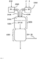
- the workup part ( 5000 ) can be subdivided into facilities for the recovery and recycling of unreacted phosgene (and for the separation of the coupled product hydrogen chloride) ( 5100 ) and in facilities for recovering the produced isocyanate in pure form (and possibly for the recovery of inert solvent) ( 5200 ) ,
- the processing part is in FIG. 1 indicated only schematically without the details listed below.
- the workup part ( 5000 ) in the devices 5100 comprises a washout column ( 5110 ) for removing isocyanate from the vapors ( 50 ) of the reaction termination zone ( 4000 ) by washing with an inert solvent, a phosgene absorption column ( 5120 ) for recovering phosgene from the Vapors of the washout column ( 5110 ) by absorption in an inert solvent, whereby hydrogen chloride and inerts ( 70 ) are separated from the phosgene, a phosgene absorption column ( 5130 ) for the separation of phosgene and inert solvent, and in the means 5200 a solvent column ( 5210 ) in particular for Separation of low-boiling components (in particular inert Solvent from the reaction termination zone ) from the crude isocyanate, a fine purification column ( 5220 ), in particular for the separation of high boilers (eg polyurea-containing residues) from the pre-purified
- the gaseous phosgene obtained is fed via the device 1100 to the mixing zone, while the separated inert solvent is preferably passed into the washout column ( 5110 ) and / or the phosgene absorption column (5120) .
- the compositions and mass flows of streams 10 and 20 are preferably coordinated so that in stream 10 phosgene ( 1 ) in a stoichiometric excess with respect to the primary amino groups of the amine ( 2 ) in stream 20 of at least 150% of theory, more preferably 160% to 350% of theory, and most preferably 170% to 300% of theory.
- one mole of phosgene reacts with one mole of amino groups, ie, theoretically, two moles of phosgene react with one mole of a diamine.
- the gaseous phosgene stream ( 10 ) may contain, in addition to phosgene ( 1 ), an inert substance ( 3 ).
- Inventive inert materials ( 3 ) are next to such substances that are already gaseous at room temperature and atmospheric pressure, such as nitrogen, helium or argon, and the vapors of inert organic solvents which are liquid at room temperature and atmospheric pressure, eg. As aromatic hydrocarbons, optionally with halogen substitution, such as. As chlorobenzene or dichlorobenzene (all isomers, preferably ortho- dichlorobenzene). Nitrogen is particularly preferably used for diluting the phosgene.
- the proportion of inert material ( 3 ) in the phosgene gas stream ( 10 ) can be selected as usual in the prior art.
- the gaseous amine stream ( 20 ) in addition to amine ( 2 ) still contain an inert material ( 3 ).
- the same inert substances ( 3 ) as described above for the phosgene gas stream ( 10 ) are possible. If both streams ( 10 and 20 ) contain an inert substance ( 3 ), the same inert substance ( 3 ) is preferably used.
- the operation of the gas phase phosgenation plant ( 100 ) at a desired value for the desired mass flow M ' target ( 2 ) can be carried out according to a method known from the prior art.
- the reaction mixture produced in the mixing zone ( 3100 ) is preferably passed continuously through the reaction zone ( 3200 ) while avoiding backmixing and preferably at a temperature of 200 ° C. to 600 ° C. and an absolute pressure of 80 mbar to 2,500 mbar within a average contact time of 0.05 to 15 seconds adiabatically or isothermally, preferably adiabatically, converted to a gaseous process product containing the desired isocyanate ( 4 ).
- Suitable embodiments are in EP 2 196 455 B1 and EP 1 935 876 B1 described.
- the gaseous process product ( 40 ) emerging from the reaction zone ( 3200 ) is rapidly cooled. This is preferably done by contacting with an inert solvent whose temperature is kept below the boiling point of the isocyanate ( 4 ) and above the decomposition temperature of the carbamic acid chloride corresponding to the reacted amine.
- Suitable embodiments are in EP 1 935 875 B1 described.
- uncondensed isocyanate ( 4 ) in this step is preferably separated off from the gaseous mixture remaining in the reaction termination zone by washing with a scrubbing liquid and preferably combined with the condensate ( 60 ) obtained in the reaction termination zone ( 4000 ).
- a suitable embodiment is in EP 1 935 875 B1 in particular in paragraphs [0024] and [0025].
- the desired isocyanate ( 4 ) is isolated by distillation from the thus obtained crude liquid process product ( 60 ).
- Suitable embodiments are known in the art and, for example, in WO 2013/139703 .
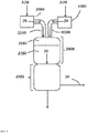
- step (I) of the process according to the invention the shutdown of the amine feed takes place in the mixing and reaction zone. This is done by reducing the registered in the device 2000 Amine mass flow M '( 2 ) of the value M' target ( 2 ) to zero. This reduction takes place steplessly or in stages, preferably continuously.
- an inert gas stream ( 30 ) is maintained through means 2100, mixing zone ( 3100 ), reaction zone ( 3200 ) and reaction termination zone ( 4000 ) (see also US Pat FIG. 2 ).
- the inert gas stream ( 30 ) consists of at least one inert substance ( 3 ), the same inert substances are suitable, as described above for the optional dilution of the phosgene in the gas stream ( 10 ).
- This inert gas stream ( 30 ) preferably has a temperature above the dew point of the amine ( 2 ) under the present pressure conditions. However, the temperature is preferably not so high that thermal decomposition of the starting materials or products still present in the apparatus would be to be feared.
- a temperature in the range from 200 ° C. to 600 ° C., particularly preferably in the range from 200 ° C. to 500 ° C. and very particularly preferably in the range from 250 ° C. to 500 ° C. is preferred.
- the maintenance of the inert gas stream ( 30 ) in step (I) can be done by ( a ) an inert material ( 3 ), preferably liquid at room temperature and normal pressure, having a temperature T 3 which is lower than that for the inert gas stream ( 30 ) in step (I ) target temperature (ie, preferably less than 200 ° C) is introduced into the device 2000 , heated there and then passed into the device 2100 and the other parts to be inerted plant parts.
- target temperature ie, preferably less than 200 ° C
- the inert gas stream ( 30 ) is provided in the device 2000 .
- This embodiment is particularly advantageous when the reaction mixture is diluted during the reaction in normal operation with the vapors of an inert material ( 3 ) present in liquid form at room temperature and normal pressure.
- inert substance ( 3 ) it is possible to introduce the inert substance ( 3 ) into the device 2000 in liquid form and to evaporate there first.
- inert substances ( 3 ) are inert solvents such as aromatic hydrocarbons, optionally with halogen substitution, such as.
- chlorobenzene or Dichlorobenzene all isomers, preferably ortho- dichlorobenzene.
- the inert substance ( 3 ) is heated (ie vaporized upon entry as liquid) to give an inert gas stream ( 30 ) having a temperature T 30 of preferably 200 ° C to 600 ° C, more preferably 200 ° C to 500 ° C and most preferably 250 ° C to 500 ° C, and an absolute pressure p 30 of preferably 100 mbar to 3,000 mbar, more preferably 150 mbar to 2,800 mbar and most preferably 200 mbar to 2,500 mbar.
- the streams ( 3 ) and ( 30 ) do not differ in their chemical composition, but only in temperature and possibly pressure.
- inert gas stream ( 30 ) having a temperature T 30 of preferably 200 ° C to 600 ° C, more preferably 200 ° C to 500 ° C and most preferably 250 ° C to 500 ° C ° C, and an absolute pressure p 30 of preferably 100 mbar to 3000 mbar, more preferably 150 mbar to 2800 mbar and most preferably 200 mbar to 2500 mbar, initiate and from there into the device 2100 and the other parts to be inerted to be transferred , It is also possible in this embodiment to further heat the introduced inert gas stream ( 30 ) in the device 2000 within the previously defined temperature ranges.
- the inert gas stream ( 30 ) can also be fed directly into the device 2100 .
- the pipeline between the device 2000 and the mixing zone (3100) forming part of the device 2100 is closed, more preferably immediately behind the device 2000.
- variant (A) no matter in which embodiment, is particularly advantageous when the reaction mixture is diluted during the reaction in the normal operation with an already gaseous at room temperature and atmospheric pressure inert material such as nitrogen, helium or argon.
- the pressure in the apparatus 2000 P 2000 by feeding the Inertstoffstroms (30) is adjusted to a value preferably lying above the pressure p 3100 in the mixing zone (3100) .
- the value for p 3100 is preferably 80 mbar (absolute) to 2,500 mbar (absolute), while the value p 2000 is preferably 100 mbar (absolute) to 3,000 mbar (absolute).
- step (II) of the method according to the invention the mass flow of phosgene M '( 1 ) leaving the device 1000 is reduced from the value M' target (1) to zero. This is done continuously or in stages, preferably continuously. Step (II) becomes particularly preferred only after a lapse of a period of at least 10 times the residence time, preferably at least 30 times the residence time at least 60 times the residence time, most preferably at least 90 times the residence time, of phosgene ( 1 ) leaving the device 1000 to exit from the reaction termination zone ( 4000 ) during normal operation of the gas phase phosgenation plant ( 100 ), calculated from the time of from which M ' (2) is zero.
- a gaseous inert gas stream ( 30 ) through the device 1100, the mixing zone ( 3100 ), the reaction zone ( 3200 ) and the reaction termination zone ( 4000 ) is maintained (see also FIG. 3 ).
- the inert gas stream ( 30 ) consists of at least one gaseous inert material ( 3 ), wherein the same inert substances are suitable, as described above for the optional dilution of the phosgene in the gas stream ( 10 ).
- the maintenance of the inert gas stream ( 30 ) in step (II) can be done by ( a ) an inert material ( 3 ), preferably liquid at room temperature and normal pressure, having a temperature T 3 which is lower than that for the inert gas stream ( 30 ) in step (II ) target temperature is introduced into the device 1000 , heated there and then passed into the device 1100 and the other parts of the system to be inerted.
- the temperature of the inert gas stream ( 30 ) of step (II) is from 200 ° C to 600 ° C, more preferably from 200 ° C to 500 ° C, and most preferably from 250 ° C to 500 ° C.
- inert substance ( 3 ) is inert solvents such as aromatic hydrocarbons, optionally with halogen substitution, such as.
- inert solvents such as aromatic hydrocarbons, optionally with halogen substitution, such as.
- chlorobenzene or dichlorobenzene all isomers, preferably ortho- dichlorobenzene.
- the inert substance ( 3 ) is heated (ie evaporated when introduced as a liquid) to give an inert gas stream ( 30 ) having a temperature T 30 of preferably 200 ° C to 600 ° C, more preferably 200 ° C to 500 ° C and most preferably 250 ° C to 500 ° C, and an absolute pressure p 30 of preferably 100 mbar to 3,000 mbar, more preferably 150 mbar to 2,800 mbar and most preferably 200 mbar to 2,500 mbar.
- the streams ( 3 ) and ( 30 ) do not differ in their chemical composition, but only in temperature and possibly pressure.
- step (I) is carried out according to variant (a), it is preferred to also carry out step (II) according to variant (a).
- an inert gas stream ( 30 ) having a temperature T 30 of preferably 200 ° C to 600 ° C, more preferably 200 ° C to 500 ° C and most preferably 250 ° C to 500 ° C ° C, and an absolute pressure p 30 of preferably 100 mbar to 3,000 mbar, more preferably 150 mbar to 2,800 mbar and most preferably 200 mbar to 2,500 mbar, to initiate. It is also possible in this embodiment to further heat the introduced inert gas stream ( 30 ) in the device 1000 within the previously defined temperature ranges. Alternatively, the inert gas stream ( 30 ) may also be fed directly into the device 1100 .
- Variant (b) no matter in which embodiment, is particularly advantageous when the reaction mixture is diluted during the reaction in normal operation with an inert material such as nitrogen, helium or argon already present in gaseous form at room temperature and atmospheric pressure. If step (I) is carried out according to variant (b), it is preferred to also carry out step (II) according to variant (b).
- step (II) only after a period of at least 10 times the residence time, preferably at least 30 times the residence time, more preferably at least 60 times the residence time, most preferably at least 90 times the residence time of phosgene ( 1 ) from the exit from the device 1000 to the exit from the reaction termination zone ( 4000 ) in the regular operation of the gas phase phosgenation plant ( 100 ), calculated from the time from which M ' (2) is zero, causes residual amounts of unreacted amine ( 2 ) can be phosgenated.
- steps (I) and (II) are preferably within less than 12 hours, preferably within less than 6 hours, more preferably within less than 3 hours, and all most preferably carried out in less than 1 hour.
- Inert gas flows (30) of identical composition are preferably used in steps (I) and (II).
- the inert gas stream ( 30 ) from (I) is maintained (III) for at least a period which is three times, preferably 100 times, more preferably 200 times, most preferably 350 times, the residence time of the inert gas stream ( 30 ). from entry into the mixing zone ( 3100 ) to exit from the reaction termination zone ( 4000 ), from the time when the mass flow of phosgene M '( 1 ) leaving the apparatus 1000 is zero.
- the inert gas stream from (II) is also maintained during this process, in which case the residence time of the combined inert gas streams from (I) and (II) is decisive. Following step (III), it may be possible - after cooling - to open system parts for maintenance work.
- the inert gas streams ( 30 ) from steps (I) and (II) are preferably discharged after exit from the reaction termination zone ( 4000 ) or, if present, preferably after passing through at least parts of the reprocessing devices 5100, via an exhaust gas discharge.
- the inert gas streams ( 30 ) from steps (I) and (II) preferably pass through the above-described apparatus washout column ( 5110 ) and phosgene absorption column ( 5120 ) and are subsequently discharged.
- reaction zones ( 3200 ) are to be operated in parallel, it is preferred, but not mandatory, to take them out of operation in succession as described above.
- the ancillary systems such as the HCl absorption, phosgene absorption, if necessary, solvent work-up or also the exhaust gas treatment) must be dimensioned so that the quantities of inert gas streams ( 30 ) required for the shutdown can be handled.
- Phosgene can flow into the device 2100 (preferably Amindüse) and it can lead to blockages, caking with polyurea, etc.
- desired phosgene excess in the continuous production at desired mass flow M ' target ( 2 ) is at least significantly undershot, at least for a short time, whereby by-products are formed because the flow equilibria are disturbed and uncontrolled mixing occurs.
- the residence time of the educts in the reaction space is disturbed if both reactant streams are switched off at the same time.
- the process of the present invention enables smooth reconnection of the plant and subsequent workup of the resulting crude isocyanate in a technically smooth manner with reduced or, ideally, no downtime with directly high end product quality. Elaborate cleaning work during a standstill can be avoided or at least reduced in scope.
- Ingredients in ppm or% are mass fractions based on the total mass of the respective substance (s).
- Toluene diamine (TDA) ( 2 ) is continuously evaporated in an amine evaporator ( 2000 ) together with nitrogen ( 3 ).
- the residence time of the TDA stream ( 20 ) from leaving the evaporator ( 2000 ) to the exit from the Amindüse is 5 seconds.
- the phosgene used is a mixture of fresh phosgene ( 1 ') and phosgene ( 1 " ) recovered in the working-up section ( 5000 ), mixing the two starting materials well and avoiding backmixing
- the temperature of the gaseous TDA stream ( 20 ) Nozzle mouth is 380 ° C (TDA has about 1 second residence time at this temperature in the inlet to the nozzle mouth.)
- the gaseous phosgene ( 10 ) has a temperature of 320 ° C when leaving the phosgene rectifier, wherein the residence time of the hot phosgene between last phosgene superheater and
- the gaseous mixture of streams ( 10 ) and ( 20 ) has a residence time of 8 seconds in the gas phase reactor ( 3000 ) and reacts at an absolute pressure of 1,692 mbar to form a gaseous reaction mixture ( 40 ).
- 4000 comprises a two-stage "quench” in which the gaseous reaction mixture ( 40 ) by spraying Ortho-dichlorobenzene (ODB) is cooled to 168 ° C, so that it condenses and in the sump ( 4100 ) a mixture ( 60 ) of crude TDI and ODB accumulates.
- ODB Ortho-dichlorobenzene
- Excess phosgene, formed in the reaction of hydrogen chloride and inert are largely degassed under these conditions from the bottom tank ( 4100 ), the entrainment of TDI is reduced by means of internals.
- This process residual gas stream ( 50 ) is used to recover entrained TDI, phosgene and hydrogen chloride, as in WO 2011/003532 , Page 11, lines 24 to 25 described, worked up ( 5100 ).
- the mixture ( 60 ) from the sump tank ( 4100 ) becomes, as in EP 1 413 571 B1 worked up ( 5200 ), wherein TDI ( 4 ) is obtained in a flow rate of 15.6 t / h.
- TDI ( 4 ) typically has a purity of> 99.97% (gas chromatography, GC), a residual solvent content of ODB of ⁇ 5 ppm (GC), a residual chlorine content of hydrolyzable chlorine of ⁇ 10 ppm (titration according to ASTM D4663), an acidity of bound chlorine ⁇ 5 ppm (titration according to ASTM D5629), and the color number, measured as a number of hazards, is ⁇ 15 (determined according to DIN EN ISO 6271).
- Comparative Example 1 Decommissioning of a Gas-Phase Phosgenation Plant (100) by Switching Off the Supply of Phosgene Before the Amine Supply
- a gas phase phosgenation plant ( 100 ) is operated at a production capacity of 15.6 t / h TDI as described in the general conditions for the production of TDI and then taken out of service as follows:
- the phosgene supply is interrupted while the amine supply is maintained for about 2 minutes.
- the amine TDA is no longer completely phosgenated during this time and the resulting intermediates and by-products clog the mixing zone ( 3100 ), the reaction zone ( 3200 ) and the subsequent reaction quench zone ("quench", 4000 ).
- the differential pressure of entry of the educts TDA gas stream ( 20 ) and phosgene gas stream ( 10 ) into the phosgenation reactor ( 3000 ) via the vapor gas outlet of the bottom of the reaction termination zone ( 4000 ) to the TDI wash column ( 5110 ) increases within the short time during the phosgene gas stream ( 10 ) was interrupted and the amine gas stream ( 20 ) continued to run (about 2 minutes) to 913 mbar instead of 10 mbar during normal operation. Cleaning the reactor and its periphery must be done before it can be restarted.
- Comparative Example 2 Decommissioning of a Gas Phase Phosphorization Plant (100) with Simultaneous Stopping of the Amine and Phosgene Feed
- the gas-phase plant ( 100 ) is operated at a production capacity of 15.6 t / h TDI as described in the general conditions for the production of TDI and then taken out of service as follows:
- the phosgene generator is turned off. Thereafter, the amine and phosgene feed to the phosgenation reactor ( 3000 ) are simultaneously interrupted. Subsequently, the phosgenation reactor (3000) is rendered inert with nitrogen until the phosgenation reactor and its piping periphery are freed from educts and product.
- the amine evaporator including downstream heat exchanger ( 2000 ) and the devices 2100 including the Amindüse be exposed to nitrogen, with a temperature of 380 ° C is set.
- the phosgenation reactor ( 3000 ) is educt-free and product-free and rendered inert with hot nitrogen.
- the amine evaporation in the amine evaporator is started so that TDA evaporates at 300 ° C.
- the TDA is gradually heated in other heat exchangers to 380 ° C and injected as a gaseous TDA stream ( 20 ) of a pressure of 1,691 mbar (absolute) through the Amindüse in the Phosgenierreaktor ( 3000 ).
- the Phosgenweg is opened, and a phosgene gas stream ( 10 ) with a mass flow of 61 t / h and a temperature of 320 ° C and a pressure of 1691 mbar (absolute) at the reactor inlet into the phosgenation reactor ( 3000 ) injected.
- the system reaches the control mode state after 45 minutes.
- the system After 7 days, the system must be shut down because the differential pressure of entry of the reactants TDA gas stream ( 20 ) and phosgene gas stream ( 10 ) in the phosgenation reactor ( 3000 ) on the vapor outlet at the bottom of the reaction termination zone ( 4000 ) to the TDI wash column ( 5110 ) over time to 793 mbar, instead of 10 mbar in normal operation, has risen, and the energy needed to vaporize phosgene and TDA and transfer of the gas streams ( 10 ) and ( 20 ) in the Phosgenierreaktor ( 3000 ) are hardly applied can (the boiling temperature of the TDA ( 2 ) limits the evaporator capacity with increasing pressure).
- polyurea-containing massive deposits are found at the outlet of the amine nozzle, along the surface of the reactor space and on the surfaces of the quench.
- a gas phase production plant ( 100 ) is operated at a production capacity of 15.6 t / h TDI as described in the general conditions for the production of TDI and then taken out of service as follows:
- the amine feed to the phosgenation reactor ( 3000 ) is stopped by closing the reactant-carrying line (part of the 2100 device) behind the amine evaporator ( 2000 ).
- An inert gas purge of the device 2100 is not performed.
- the phosgene generator is turned off, thus interrupting the supply of fresh phosgene ( 1 ').
- the phosgene cycle is shut down by the supply of recycled material -Phosgen (1 ") to the phosgenation reactor (3000) is interrupted. then, the phosgenation reactor (3000) is rendered inert with nitrogen.
- a phosgene cycle is established by recycling recycle phosgene ( 1 " ) from the workup ( 5100 ) of the vapors ( 50 ) of the reaction termination zone ( 4000 ) at a temperature of 320 ° C via the phosgenation reactor ( 3000 ), the reaction termination zone ( 4000 ) is moved back to the work-up. in the reaction termination zone (4000) during which only the (in the direction of flow of the reaction mixture 40) second quench in operation, so that the phosgene stream is cooled. in this Phosgen Vietnameselauf 61 t / h of phosgene are circulated. the loop 2100 including the Amindüse during its purged with a nitrogen gas stream (30).
- the amine evaporation is started by to 220 ° C pre-heated, liquid TDA (2) together with nitrogen in the amine evaporator (2000) is driven there, with the aid of a heat exchanger at 300 ° C and then evaporated with e is heated in a further heat exchanger at 410 ° C.
- the resulting TDA stream ( 20 ) is injected at an absolute pressure of 1654 mbar through the amine nozzle into the phosgenation reactor ( 3000 ).
- the amount of TDA ( 2 ) introduced into the phosgenation reactor ( 3000 ) during the start-up of the gas phase phosgenation unit ie, until the amine mass flow M'Soll ( 2 ) is reached, which is the case after 45 minutes) is infinitely variable 0 t / h increased to 12 t / h, the operating pressure in the phosgenation reactor ( 3000 ) at the end of commissioning is 1641 mbar (absolute).
- the first quencher in the flow direction of the reaction mixture ( 40 ) is put into operation shortly before the TDA gas stream ( 20 ) leaves the amine nozzle in the direction of the phosgenation reactor ( 3000 ) during commissioning.
- the phosgene consumed after the start of the plant is replaced by a mixture of fresh phosgene ( 1 ' ) and phosgene ( 1 ") recovered in the workup After 15 minutes 15.6 t / h of TDI ( 4 ) leave the last distillation column of workup stage.
- the gas phase phosgenation plant ( 100 ) is operated at a production capacity of 15.6 t / h TDI as described in the general conditions for the production of TDI and taken out of service as follows:
- the amine feed to the phosgenation reactor ( 3000 ) is stopped by closing the reactant-carrying line (part of the 2100 device) behind the amine evaporator ( 2000 ). Meanwhile, a gaseous nitrogen flow through the device 2100, the mixing zone (3100), the reaction zone (3200), the termination of the reaction zone (4000) and parts of the device 5100 (5120 Auswaschkolonne and Phosgenabsorptionskolonne 5120, both in FIG. 1 not shown) (step (I) of the method of the invention).
- the phosgene generator After reduction of the amine mass flow M '( 2 ) to zero, the phosgene generator is turned off, thus interrupting the supply of fresh phosgene ( 1' ) (step (II.a) of the process according to the invention).
- step (II.a) of the process according to the invention After 30 seconds (corresponding to about 4 times the residence time of phosgene (1) from exit from the device 1000 to exit from the reaction termination zone ( 4000 ) in the regular operation of the gas phase phosgenation (100)) the phosgene cycle is shut down by the supply of recycled material -Phosgen (1 ") to the phosgenation reactor (3000) is discontinued (step (II.b) of the process according to the invention).
- the device 1100, the reactor (3000), the termination of the reaction zone (4000) and parts of the device 5100 (Auswaschkolonne 5120 and Phosgenabsorptionskolonne 5120, both in FIG. 1 not shown) with nitrogen, which leaves the device 5100 by discharge from the phosgene absorption column ( 5120 ).
- the nitrogen streams from steps (I), (II.a) and (II.b) are after interruption of the phosgene cycle for 1 hour (corresponding to about 400 times the residence time of the combined inert gas streams ( 30 ) of entry into the mixing zone ( 3100 ) until exit from the reaction termination zone (4000)) (step (III) of the process according to the invention), after which the phosgenation reactor (3000) is freed from the educts and product.
- the operating pressure in the phosgenation reactor (3000) is 1651 mbar (absolute).
- the system must be turned off because the differential pressure of entry of the educts TDA gas stream (20) and phosgene gas stream ( 10 ) in the phosgenation reactor ( 3000 ) on the vapor outlet at the bottom of the reaction termination zone ( 4000 ) to the TDI wash column ( 5110 ) over time to 803 mbar, instead of 10 mbar in normal operation, has risen, and the energy needed to evaporate phosgene and TDA and transfer of the gas streams ( 10 ) and ( 20 ) in the Phosgenierreaktor ( 3000 ) are hardly applied can (the boiling temperature of the TDA ( 2 ) limits the evaporator capacity with increasing pressure).
- polyurea-containing massive deposits are found at the outlet of the amine nozzle, along the surface of the reactor space and on the surfaces of
- the gas phase phosgenation plant ( 100 ) is operated at a production capacity of 15.6 t / h TDI as described in the general conditions for the production of TDI and taken out of service as follows:
- the amine feed to the phosgenation reactor ( 3000 ) is stopped by closing the reactant-carrying line (part of the 2100 device) behind the amine evaporator ( 2000 ). Meanwhile, a gaseous nitrogen flow through the device 2100, the mixing zone (3100), the reaction zone (3200), the termination of the reaction zone (4000) and parts of the device 5100 (5120 Auswaschkolonne and Phosgenabsorptionskolonne 5120, both in FIG. 1 not shown) (step (I) of the method of the invention).
- step (II.a) of the process according to the invention After reduction of the amine mass flow M ' (2) to zero, the phosgene generator is turned off, thus interrupting the supply of fresh phosgene (1') (step (II.a) of the process according to the invention). After 15 minutes (corresponding to approximately 112 times the residence time of phosgene ( 1 ) from the outlet from the device 1000 to exit from the reaction termination zone ( 4000 ) in the regular operation of the gas phase (100) ) the phosgene cycle is shut down by the supply of recycled material -Phosgene ( 1 " ) to the phosgenation reactor ( 3000 ) is interrupted (step (II.b) of the invention Procedure).
- the nitrogen streams from steps (I), (II.a) and (II.b) are after interruption of the phosgene cycle for 1 hour (corresponding to about 400 times the residence time of the combined inert gas streams ( 30 ) of entry into the mixing zone ( 3100 ) until leaving the reaction termination zone (4000)) (step (III) of the process according to the invention), after which the phosgenation reactor ( 3000 ) is freed from the educts and product.
- Example 5 no blocking of the Amindüse and no formation of deposits in the Phosgenierreaktor are observed during decommissioning.
- the system can be put back into operation without problems and operated over a further phosgenation cycle of several months.
- the formation of unwanted by-products such as polyureas etc. is significantly reduced and the starting material is of high quality so that it does not have to be blended with TDI produced at a later date.
Landscapes
- Chemical & Material Sciences (AREA)
- Organic Chemistry (AREA)
- Chemical Kinetics & Catalysis (AREA)
- Organic Low-Molecular-Weight Compounds And Preparation Thereof (AREA)
Applications Claiming Priority (2)
| Application Number | Priority Date | Filing Date | Title |
|---|---|---|---|
| EP14162002 | 2014-03-27 | ||
| PCT/EP2015/056216 WO2015144682A1 (de) | 2014-03-27 | 2015-03-24 | Verfahren zum betreiben einer gasphasenphosgenierungsanlage |
Publications (2)
| Publication Number | Publication Date |
|---|---|
| EP3122720A1 EP3122720A1 (de) | 2017-02-01 |
| EP3122720B1 true EP3122720B1 (de) | 2018-06-13 |
Family
ID=50382339
Family Applications (1)
| Application Number | Title | Priority Date | Filing Date |
|---|---|---|---|
| EP15711761.5A Active EP3122720B1 (de) | 2014-03-27 | 2015-03-24 | Verfahren zum betreiben einer gasphasenphosgenierungsanlage |
Country Status (7)
| Country | Link |
|---|---|
| US (1) | US9845286B2 (enExample) |
| EP (1) | EP3122720B1 (enExample) |
| JP (1) | JP6621759B2 (enExample) |
| KR (1) | KR20160137544A (enExample) |
| CN (1) | CN106458864B (enExample) |
| HU (1) | HUE039136T2 (enExample) |
| WO (1) | WO2015144682A1 (enExample) |
Families Citing this family (5)
| Publication number | Priority date | Publication date | Assignee | Title |
|---|---|---|---|---|
| EP3421426A1 (de) * | 2017-06-29 | 2019-01-02 | Covestro Deutschland AG | Energieeffizientes verfahren zur bereitstellung von phosgen-dampf |
| US11365172B2 (en) * | 2017-07-03 | 2022-06-21 | Covestro Deutschland Ag | Production plant for producing a chemical product by reacting H-functional reactants with phosgene, and method for operating same with an interruption to production |
| EP3453700A1 (de) * | 2017-09-06 | 2019-03-13 | Covestro Deutschland AG | Verfahren zur reinigung phosgen-führender apparate |
| EP3678766B1 (en) * | 2017-09-06 | 2022-06-01 | Covestro Intellectual Property GmbH & Co. KG | Method for cleaning phosgene-conducting apparatuses |
| CN114195683B (zh) * | 2021-12-14 | 2023-03-17 | 山东新和成维生素有限公司 | 一种采用气相反应器制备异氰酸酯的方法及气相反应器 |
Family Cites Families (27)
| Publication number | Priority date | Publication date | Assignee | Title |
|---|---|---|---|---|
| JPS3510774B1 (enExample) * | 1954-12-01 | 1960-08-08 | ||
| DE3121036A1 (de) * | 1981-05-27 | 1982-12-16 | Bayer Ag, 5090 Leverkusen | Verfahren zur kontinuierlicehn herstellung von organischen mono- oder polyisocyanaten |
| FR2723585B1 (fr) | 1994-08-12 | 1996-09-27 | Rhone Poulenc Chimie | Procede de preparation de composes du type polyisocyanates aromatiques en phase gazeuse. |
| DE19942299A1 (de) * | 1999-09-04 | 2001-03-08 | Basf Ag | Verbessertes Verfahren zur Herstellung von Mono- und Oligo-Isocyanaten |
| DE10158160A1 (de) | 2001-11-28 | 2003-06-12 | Basf Ag | Herstellung von Isocyanaten in der Gasphase |
| DE10161384A1 (de) * | 2001-12-14 | 2003-06-18 | Bayer Ag | Verbessertes Verfahren für die Herstellung von (/Poly)-isocyanaten in der Gasphase |
| EP1371633A1 (en) | 2002-06-14 | 2003-12-17 | Bayer Ag | Process for the purification of mixtures of toluenediisocyanate incorporating a dividing-wall distillation column |
| EP1371634A1 (en) | 2002-06-14 | 2003-12-17 | Bayer Ag | Process for the purification of mixtures of toluenediisocyanate |
| ES2271171T3 (es) | 2002-10-22 | 2007-04-16 | Bayer Materialscience Ag | Procedimiento para la purificacion de toluendiisocianato que incorpora una columna de destilacion de pared divisoria para la purificacion final. |
| DE10260082A1 (de) * | 2002-12-19 | 2004-07-01 | Basf Ag | Verfahren zur kontinuierlichen Herstellung von Isocyanaten |
| DE10307141A1 (de) * | 2003-02-20 | 2004-09-02 | Bayer Ag | Verfahren zur Herstellung von (Poly)isocyanaten in der Gasphase |
| DE10349504A1 (de) | 2003-10-23 | 2005-05-25 | Bayer Technology Services Gmbh | Verfahren zur Herstellung von Isocyanaten in der Gasphase |
| DE102005036870A1 (de) | 2005-08-02 | 2007-02-08 | Bayer Materialscience Ag | Verfahren zur Gasphasenphosgenierung |
| DE102005037328A1 (de) | 2005-08-04 | 2007-02-08 | Basf Ag | Verfahren zur Herstellung von Isocyanaten |
| DE102005042392A1 (de) | 2005-09-06 | 2007-03-08 | Basf Ag | Verfahren zur Herstellung von Isocyanaten |
| DE102007056511A1 (de) | 2007-11-22 | 2009-05-28 | Bayer Materialscience Ag | Verfahren zur Herstellung aromatischer Diisocyanate in der Gasphase |
| US8779181B2 (en) | 2008-10-15 | 2014-07-15 | Basf Se | Process for preparing isocyanates |
| US20110301380A1 (en) * | 2009-03-06 | 2011-12-08 | Basf Se | Process and apparatus for preparing isocyanates |
| EP2408738B1 (de) | 2009-03-20 | 2017-07-26 | Basf Se | Verfahren zur herstellung von isocyanaten |
| DE102009032413A1 (de) * | 2009-07-09 | 2011-01-13 | Bayer Materialscience Ag | Verfahren zur Herstellung von Isocyanaten |
| JP5827248B2 (ja) * | 2010-02-26 | 2015-12-02 | ビーエーエスエフ ソシエタス・ヨーロピアBasf Se | 気相においてイソシアネートを製造する方法 |
| US9321720B2 (en) * | 2010-10-14 | 2016-04-26 | Basf Se | Process for preparing isocyanates |
| US8969615B2 (en) | 2011-03-31 | 2015-03-03 | Basf Se | Process for preparing isocyanates |
| US8816126B2 (en) * | 2011-09-02 | 2014-08-26 | Basf Se | Process for preparing isocyanates |
| WO2013029918A1 (de) * | 2011-09-02 | 2013-03-07 | Basf Se | Verfahren zur herstellung von isocyanaten |
| IN2014DN07241A (enExample) | 2012-03-19 | 2015-04-24 | Bayer Ip Gmbh | |
| US9932299B2 (en) | 2013-02-08 | 2018-04-03 | Covestro Deutschland Ag | Process for separating an isocyanate prepared by phosgenation of a primary amine in the gas phase from the gaseous crude product of the phosgenation |
-
2015
- 2015-03-24 HU HUE15711761A patent/HUE039136T2/hu unknown
- 2015-03-24 WO PCT/EP2015/056216 patent/WO2015144682A1/de not_active Ceased
- 2015-03-24 JP JP2016559191A patent/JP6621759B2/ja active Active
- 2015-03-24 KR KR1020167026161A patent/KR20160137544A/ko not_active Withdrawn
- 2015-03-24 CN CN201580015929.4A patent/CN106458864B/zh active Active
- 2015-03-24 US US15/127,826 patent/US9845286B2/en active Active
- 2015-03-24 EP EP15711761.5A patent/EP3122720B1/de active Active
Non-Patent Citations (1)
| Title |
|---|
| None * |
Also Published As
| Publication number | Publication date |
|---|---|
| CN106458864B (zh) | 2020-08-11 |
| US9845286B2 (en) | 2017-12-19 |
| WO2015144682A1 (de) | 2015-10-01 |
| US20170096389A1 (en) | 2017-04-06 |
| KR20160137544A (ko) | 2016-11-30 |
| JP6621759B2 (ja) | 2019-12-18 |
| CN106458864A (zh) | 2017-02-22 |
| HUE039136T2 (hu) | 2018-12-28 |
| EP3122720A1 (de) | 2017-02-01 |
| JP2017512793A (ja) | 2017-05-25 |
Similar Documents
| Publication | Publication Date | Title |
|---|---|---|
| EP3122719B1 (de) | Verfahren zum betreiben einer gasphasenphosgenierungsanlage | |
| EP3352896B1 (de) | Verfahren zur herstellung von isocyanaten | |
| EP3122720B1 (de) | Verfahren zum betreiben einer gasphasenphosgenierungsanlage | |
| EP3122718B1 (de) | Verfahren zur herstellung von isocyanaten | |
| EP3634947B1 (de) | Verfahren zur herstellung von isocyanaten in der gasphase | |
| EP2511258A1 (de) | Verfahren zur Herstellung von Isocyanaten | |
| EP3356324B1 (de) | Verfahren zur herstellung von isocyanaten | |
| EP2828235A1 (de) | Verfahren zur herstellung von isocyanaten | |
| EP3634946B1 (de) | Verfahren zur herstellung von isocyanaten | |
| EP2199276A1 (de) | Verfahren zur Herstellung von Isocyanaten in der Gasphase | |
| EP2953928B1 (de) | Verfahren zur abtrennung eines durch phosgenierung eines primären amins in der gasphase hergestellten isocyanats aus dem gasförmigen rohprodukt der phosgenierung | |
| EP3606630B1 (de) | Reinigungsvorrichtung für gasströme aus der isocyanatherstellung | |
| EP2062876B1 (de) | Verfahren zur Herstellung aromatischer Diisocyanate in der Gasphase | |
| EP2451774B1 (de) | Verfahren zur herstellung von isocyanaten in der gasphase | |
| EP3653605B1 (de) | Verfahren zur herstellung eines isocyanats durch teilweise adiabatisch betriebene phosgenierung des korrespondierenden amins | |
| EP2197836A1 (de) | Verfahren zur herstellung von isocyanaten | |
| EP3383840B1 (de) | Verfahren zur herstellung von isocyanaten | |
| EP3307708B1 (de) | Verfahren zur herstellung von diisocyanaten in der gasphase | |
| EP2566844B1 (de) | Verfahren zur herstellung von isocyanaten in der gasphase | |
| WO2004056760A1 (de) | Verfahren zur herstellung von (cyclo)aliphatischen isocyanaten | |
| EP3649179B1 (de) | Produktionsanlage zur herstellung eines chemischen produkts durch umsetzung h-funktioneller reaktanten mit phosgen und verfahren zum betreiben derselben | |
| WO2024260925A1 (de) | Verfahren zur herstellung von aliphatischen diisocyanaten in der gasphase |
Legal Events
| Date | Code | Title | Description |
|---|---|---|---|
| STAA | Information on the status of an ep patent application or granted ep patent |
Free format text: STATUS: THE INTERNATIONAL PUBLICATION HAS BEEN MADE |
|
| PUAI | Public reference made under article 153(3) epc to a published international application that has entered the european phase |
Free format text: ORIGINAL CODE: 0009012 |
|
| STAA | Information on the status of an ep patent application or granted ep patent |
Free format text: STATUS: REQUEST FOR EXAMINATION WAS MADE |
|
| 17P | Request for examination filed |
Effective date: 20161027 |
|
| AK | Designated contracting states |
Kind code of ref document: A1 Designated state(s): AL AT BE BG CH CY CZ DE DK EE ES FI FR GB GR HR HU IE IS IT LI LT LU LV MC MK MT NL NO PL PT RO RS SE SI SK SM TR |
|
| AX | Request for extension of the european patent |
Extension state: BA ME |
|
| DAV | Request for validation of the european patent (deleted) | ||
| DAX | Request for extension of the european patent (deleted) | ||
| GRAJ | Information related to disapproval of communication of intention to grant by the applicant or resumption of examination proceedings by the epo deleted |
Free format text: ORIGINAL CODE: EPIDOSDIGR1 |
|
| STAA | Information on the status of an ep patent application or granted ep patent |
Free format text: STATUS: GRANT OF PATENT IS INTENDED |
|
| GRAP | Despatch of communication of intention to grant a patent |
Free format text: ORIGINAL CODE: EPIDOSNIGR1 |
|
| INTG | Intention to grant announced |
Effective date: 20180116 |
|
| GRAS | Grant fee paid |
Free format text: ORIGINAL CODE: EPIDOSNIGR3 |
|
| GRAA | (expected) grant |
Free format text: ORIGINAL CODE: 0009210 |
|
| STAA | Information on the status of an ep patent application or granted ep patent |
Free format text: STATUS: THE PATENT HAS BEEN GRANTED |
|
| AK | Designated contracting states |
Kind code of ref document: B1 Designated state(s): AL AT BE BG CH CY CZ DE DK EE ES FI FR GB GR HR HU IE IS IT LI LT LU LV MC MK MT NL NO PL PT RO RS SE SI SK SM TR |
|
| REG | Reference to a national code |
Ref country code: GB Ref legal event code: FG4D Free format text: NOT ENGLISH |
|
| REG | Reference to a national code |
Ref country code: CH Ref legal event code: EP Ref country code: AT Ref legal event code: REF Ref document number: 1008377 Country of ref document: AT Kind code of ref document: T Effective date: 20180615 |
|
| REG | Reference to a national code |
Ref country code: IE Ref legal event code: FG4D Free format text: LANGUAGE OF EP DOCUMENT: GERMAN |
|
| REG | Reference to a national code |
Ref country code: DE Ref legal event code: R096 Ref document number: 502015004660 Country of ref document: DE |
|
| REG | Reference to a national code |
Ref country code: NL Ref legal event code: MP Effective date: 20180613 |
|
| REG | Reference to a national code |
Ref country code: LT Ref legal event code: MG4D |
|
| PG25 | Lapsed in a contracting state [announced via postgrant information from national office to epo] |
Ref country code: ES Free format text: LAPSE BECAUSE OF FAILURE TO SUBMIT A TRANSLATION OF THE DESCRIPTION OR TO PAY THE FEE WITHIN THE PRESCRIBED TIME-LIMIT Effective date: 20180613 Ref country code: SE Free format text: LAPSE BECAUSE OF FAILURE TO SUBMIT A TRANSLATION OF THE DESCRIPTION OR TO PAY THE FEE WITHIN THE PRESCRIBED TIME-LIMIT Effective date: 20180613 Ref country code: LT Free format text: LAPSE BECAUSE OF FAILURE TO SUBMIT A TRANSLATION OF THE DESCRIPTION OR TO PAY THE FEE WITHIN THE PRESCRIBED TIME-LIMIT Effective date: 20180613 Ref country code: CY Free format text: LAPSE BECAUSE OF FAILURE TO SUBMIT A TRANSLATION OF THE DESCRIPTION OR TO PAY THE FEE WITHIN THE PRESCRIBED TIME-LIMIT Effective date: 20180613 Ref country code: NO Free format text: LAPSE BECAUSE OF FAILURE TO SUBMIT A TRANSLATION OF THE DESCRIPTION OR TO PAY THE FEE WITHIN THE PRESCRIBED TIME-LIMIT Effective date: 20180913 Ref country code: FI Free format text: LAPSE BECAUSE OF FAILURE TO SUBMIT A TRANSLATION OF THE DESCRIPTION OR TO PAY THE FEE WITHIN THE PRESCRIBED TIME-LIMIT Effective date: 20180613 Ref country code: BG Free format text: LAPSE BECAUSE OF FAILURE TO SUBMIT A TRANSLATION OF THE DESCRIPTION OR TO PAY THE FEE WITHIN THE PRESCRIBED TIME-LIMIT Effective date: 20180913 |
|
| PG25 | Lapsed in a contracting state [announced via postgrant information from national office to epo] |
Ref country code: RS Free format text: LAPSE BECAUSE OF FAILURE TO SUBMIT A TRANSLATION OF THE DESCRIPTION OR TO PAY THE FEE WITHIN THE PRESCRIBED TIME-LIMIT Effective date: 20180613 Ref country code: LV Free format text: LAPSE BECAUSE OF FAILURE TO SUBMIT A TRANSLATION OF THE DESCRIPTION OR TO PAY THE FEE WITHIN THE PRESCRIBED TIME-LIMIT Effective date: 20180613 Ref country code: GR Free format text: LAPSE BECAUSE OF FAILURE TO SUBMIT A TRANSLATION OF THE DESCRIPTION OR TO PAY THE FEE WITHIN THE PRESCRIBED TIME-LIMIT Effective date: 20180914 Ref country code: HR Free format text: LAPSE BECAUSE OF FAILURE TO SUBMIT A TRANSLATION OF THE DESCRIPTION OR TO PAY THE FEE WITHIN THE PRESCRIBED TIME-LIMIT Effective date: 20180613 |
|
| REG | Reference to a national code |
Ref country code: HU Ref legal event code: AG4A Ref document number: E039136 Country of ref document: HU |
|
| PG25 | Lapsed in a contracting state [announced via postgrant information from national office to epo] |
Ref country code: NL Free format text: LAPSE BECAUSE OF FAILURE TO SUBMIT A TRANSLATION OF THE DESCRIPTION OR TO PAY THE FEE WITHIN THE PRESCRIBED TIME-LIMIT Effective date: 20180613 |
|
| PG25 | Lapsed in a contracting state [announced via postgrant information from national office to epo] |
Ref country code: RO Free format text: LAPSE BECAUSE OF FAILURE TO SUBMIT A TRANSLATION OF THE DESCRIPTION OR TO PAY THE FEE WITHIN THE PRESCRIBED TIME-LIMIT Effective date: 20180613 Ref country code: SK Free format text: LAPSE BECAUSE OF FAILURE TO SUBMIT A TRANSLATION OF THE DESCRIPTION OR TO PAY THE FEE WITHIN THE PRESCRIBED TIME-LIMIT Effective date: 20180613 Ref country code: IS Free format text: LAPSE BECAUSE OF FAILURE TO SUBMIT A TRANSLATION OF THE DESCRIPTION OR TO PAY THE FEE WITHIN THE PRESCRIBED TIME-LIMIT Effective date: 20181013 Ref country code: EE Free format text: LAPSE BECAUSE OF FAILURE TO SUBMIT A TRANSLATION OF THE DESCRIPTION OR TO PAY THE FEE WITHIN THE PRESCRIBED TIME-LIMIT Effective date: 20180613 Ref country code: PL Free format text: LAPSE BECAUSE OF FAILURE TO SUBMIT A TRANSLATION OF THE DESCRIPTION OR TO PAY THE FEE WITHIN THE PRESCRIBED TIME-LIMIT Effective date: 20180613 Ref country code: CZ Free format text: LAPSE BECAUSE OF FAILURE TO SUBMIT A TRANSLATION OF THE DESCRIPTION OR TO PAY THE FEE WITHIN THE PRESCRIBED TIME-LIMIT Effective date: 20180613 |
|
| PG25 | Lapsed in a contracting state [announced via postgrant information from national office to epo] |
Ref country code: IT Free format text: LAPSE BECAUSE OF FAILURE TO SUBMIT A TRANSLATION OF THE DESCRIPTION OR TO PAY THE FEE WITHIN THE PRESCRIBED TIME-LIMIT Effective date: 20180613 Ref country code: SM Free format text: LAPSE BECAUSE OF FAILURE TO SUBMIT A TRANSLATION OF THE DESCRIPTION OR TO PAY THE FEE WITHIN THE PRESCRIBED TIME-LIMIT Effective date: 20180613 |
|
| REG | Reference to a national code |
Ref country code: DE Ref legal event code: R097 Ref document number: 502015004660 Country of ref document: DE |
|
| PLBE | No opposition filed within time limit |
Free format text: ORIGINAL CODE: 0009261 |
|
| STAA | Information on the status of an ep patent application or granted ep patent |
Free format text: STATUS: NO OPPOSITION FILED WITHIN TIME LIMIT |
|
| 26N | No opposition filed |
Effective date: 20190314 |
|
| PG25 | Lapsed in a contracting state [announced via postgrant information from national office to epo] |
Ref country code: DK Free format text: LAPSE BECAUSE OF FAILURE TO SUBMIT A TRANSLATION OF THE DESCRIPTION OR TO PAY THE FEE WITHIN THE PRESCRIBED TIME-LIMIT Effective date: 20180613 Ref country code: SI Free format text: LAPSE BECAUSE OF FAILURE TO SUBMIT A TRANSLATION OF THE DESCRIPTION OR TO PAY THE FEE WITHIN THE PRESCRIBED TIME-LIMIT Effective date: 20180613 |
|
| PG25 | Lapsed in a contracting state [announced via postgrant information from national office to epo] |
Ref country code: MC Free format text: LAPSE BECAUSE OF FAILURE TO SUBMIT A TRANSLATION OF THE DESCRIPTION OR TO PAY THE FEE WITHIN THE PRESCRIBED TIME-LIMIT Effective date: 20180613 |
|
| REG | Reference to a national code |
Ref country code: CH Ref legal event code: PL |
|
| GBPC | Gb: european patent ceased through non-payment of renewal fee |
Effective date: 20190324 |
|
| PG25 | Lapsed in a contracting state [announced via postgrant information from national office to epo] |
Ref country code: AL Free format text: LAPSE BECAUSE OF FAILURE TO SUBMIT A TRANSLATION OF THE DESCRIPTION OR TO PAY THE FEE WITHIN THE PRESCRIBED TIME-LIMIT Effective date: 20180613 Ref country code: LU Free format text: LAPSE BECAUSE OF NON-PAYMENT OF DUE FEES Effective date: 20190324 |
|
| REG | Reference to a national code |
Ref country code: BE Ref legal event code: MM Effective date: 20190331 |
|
| PG25 | Lapsed in a contracting state [announced via postgrant information from national office to epo] |
Ref country code: CH Free format text: LAPSE BECAUSE OF NON-PAYMENT OF DUE FEES Effective date: 20190331 Ref country code: LI Free format text: LAPSE BECAUSE OF NON-PAYMENT OF DUE FEES Effective date: 20190331 Ref country code: IE Free format text: LAPSE BECAUSE OF NON-PAYMENT OF DUE FEES Effective date: 20190324 Ref country code: GB Free format text: LAPSE BECAUSE OF NON-PAYMENT OF DUE FEES Effective date: 20190324 |
|
| PG25 | Lapsed in a contracting state [announced via postgrant information from national office to epo] |
Ref country code: BE Free format text: LAPSE BECAUSE OF NON-PAYMENT OF DUE FEES Effective date: 20190331 |
|
| PG25 | Lapsed in a contracting state [announced via postgrant information from national office to epo] |
Ref country code: TR Free format text: LAPSE BECAUSE OF FAILURE TO SUBMIT A TRANSLATION OF THE DESCRIPTION OR TO PAY THE FEE WITHIN THE PRESCRIBED TIME-LIMIT Effective date: 20180613 |
|
| PG25 | Lapsed in a contracting state [announced via postgrant information from national office to epo] |
Ref country code: PT Free format text: LAPSE BECAUSE OF FAILURE TO SUBMIT A TRANSLATION OF THE DESCRIPTION OR TO PAY THE FEE WITHIN THE PRESCRIBED TIME-LIMIT Effective date: 20181015 Ref country code: MT Free format text: LAPSE BECAUSE OF FAILURE TO SUBMIT A TRANSLATION OF THE DESCRIPTION OR TO PAY THE FEE WITHIN THE PRESCRIBED TIME-LIMIT Effective date: 20180613 |
|
| PGFP | Annual fee paid to national office [announced via postgrant information from national office to epo] |
Ref country code: FR Payment date: 20210225 Year of fee payment: 7 |
|
| REG | Reference to a national code |
Ref country code: AT Ref legal event code: MM01 Ref document number: 1008377 Country of ref document: AT Kind code of ref document: T Effective date: 20200324 |
|
| PG25 | Lapsed in a contracting state [announced via postgrant information from national office to epo] |
Ref country code: AT Free format text: LAPSE BECAUSE OF NON-PAYMENT OF DUE FEES Effective date: 20200324 |
|
| PGFP | Annual fee paid to national office [announced via postgrant information from national office to epo] |
Ref country code: HU Payment date: 20220306 Year of fee payment: 8 |
|
| PG25 | Lapsed in a contracting state [announced via postgrant information from national office to epo] |
Ref country code: MK Free format text: LAPSE BECAUSE OF FAILURE TO SUBMIT A TRANSLATION OF THE DESCRIPTION OR TO PAY THE FEE WITHIN THE PRESCRIBED TIME-LIMIT Effective date: 20180613 |
|
| PG25 | Lapsed in a contracting state [announced via postgrant information from national office to epo] |
Ref country code: FR Free format text: LAPSE BECAUSE OF NON-PAYMENT OF DUE FEES Effective date: 20220331 |
|
| PG25 | Lapsed in a contracting state [announced via postgrant information from national office to epo] |
Ref country code: HU Free format text: LAPSE BECAUSE OF NON-PAYMENT OF DUE FEES Effective date: 20230325 |
|
| PGFP | Annual fee paid to national office [announced via postgrant information from national office to epo] |
Ref country code: DE Payment date: 20260218 Year of fee payment: 12 |