EP3122720B1 - Method for operating a gas phase phosgenation system - Google Patents
Method for operating a gas phase phosgenation system Download PDFInfo
- Publication number
- EP3122720B1 EP3122720B1 EP15711761.5A EP15711761A EP3122720B1 EP 3122720 B1 EP3122720 B1 EP 3122720B1 EP 15711761 A EP15711761 A EP 15711761A EP 3122720 B1 EP3122720 B1 EP 3122720B1
- Authority
- EP
- European Patent Office
- Prior art keywords
- phosgene
- zone
- reaction
- amine
- gas phase
- Prior art date
- Legal status (The legal status is an assumption and is not a legal conclusion. Google has not performed a legal analysis and makes no representation as to the accuracy of the status listed.)
- Active
Links
- 238000000034 method Methods 0.000 title claims description 66
- YGYAWVDWMABLBF-UHFFFAOYSA-N Phosgene Chemical compound ClC(Cl)=O YGYAWVDWMABLBF-UHFFFAOYSA-N 0.000 claims description 255
- 238000006243 chemical reaction Methods 0.000 claims description 127
- 239000007789 gas Substances 0.000 claims description 118
- 150000001412 amines Chemical class 0.000 claims description 113
- VOZKAJLKRJDJLL-UHFFFAOYSA-N tolylenediamine group Chemical group CC1=C(C=C(C=C1)N)N VOZKAJLKRJDJLL-UHFFFAOYSA-N 0.000 claims description 73
- 239000011261 inert gas Substances 0.000 claims description 64
- 238000002156 mixing Methods 0.000 claims description 63
- 230000008569 process Effects 0.000 claims description 35
- 150000002513 isocyanates Chemical class 0.000 claims description 32
- 239000012948 isocyanate Substances 0.000 claims description 30
- 239000000126 substance Substances 0.000 claims description 25
- 238000010626 work up procedure Methods 0.000 claims description 19
- 239000007788 liquid Substances 0.000 claims description 17
- 239000000203 mixture Substances 0.000 claims description 15
- 239000012442 inert solvent Substances 0.000 claims description 12
- 238000009835 boiling Methods 0.000 claims description 8
- 238000012423 maintenance Methods 0.000 claims description 7
- NAQMVNRVTILPCV-UHFFFAOYSA-N hexane-1,6-diamine Chemical compound NCCCCCCN NAQMVNRVTILPCV-UHFFFAOYSA-N 0.000 claims description 4
- 125000002924 primary amino group Chemical group [H]N([H])* 0.000 claims description 4
- 238000011084 recovery Methods 0.000 claims description 3
- RNLHGQLZWXBQNY-UHFFFAOYSA-N 3-(aminomethyl)-3,5,5-trimethylcyclohexan-1-amine Chemical compound CC1(C)CC(N)CC(C)(CN)C1 RNLHGQLZWXBQNY-UHFFFAOYSA-N 0.000 claims description 2
- DZIHTWJGPDVSGE-UHFFFAOYSA-N 4-[(4-aminocyclohexyl)methyl]cyclohexan-1-amine Chemical compound C1CC(N)CCC1CC1CCC(N)CC1 DZIHTWJGPDVSGE-UHFFFAOYSA-N 0.000 claims description 2
- CKDWPUIZGOQOOM-UHFFFAOYSA-N Carbamyl chloride Chemical compound NC(Cl)=O CKDWPUIZGOQOOM-UHFFFAOYSA-N 0.000 claims description 2
- ZZTCPWRAHWXWCH-UHFFFAOYSA-N diphenylmethanediamine Chemical compound C=1C=CC=CC=1C(N)(N)C1=CC=CC=C1 ZZTCPWRAHWXWCH-UHFFFAOYSA-N 0.000 claims description 2
- 238000010438 heat treatment Methods 0.000 claims 2
- 230000015556 catabolic process Effects 0.000 claims 1
- 239000012071 phase Substances 0.000 description 77
- IJGRMHOSHXDMSA-UHFFFAOYSA-N Atomic nitrogen Chemical compound N#N IJGRMHOSHXDMSA-UHFFFAOYSA-N 0.000 description 33
- 238000004519 manufacturing process Methods 0.000 description 28
- DVKJHBMWWAPEIU-UHFFFAOYSA-N toluene 2,4-diisocyanate Chemical compound CC1=CC=C(N=C=O)C=C1N=C=O DVKJHBMWWAPEIU-UHFFFAOYSA-N 0.000 description 23
- RFFLAFLAYFXFSW-UHFFFAOYSA-N 1,2-dichlorobenzene Chemical compound ClC1=CC=CC=C1Cl RFFLAFLAYFXFSW-UHFFFAOYSA-N 0.000 description 20
- 239000000463 material Substances 0.000 description 16
- 229910052757 nitrogen Inorganic materials 0.000 description 16
- OWIKHYCFFJSOEH-UHFFFAOYSA-N Isocyanic acid Chemical compound N=C=O OWIKHYCFFJSOEH-UHFFFAOYSA-N 0.000 description 15
- 239000000047 product Substances 0.000 description 15
- 239000011541 reaction mixture Substances 0.000 description 14
- 238000010521 absorption reaction Methods 0.000 description 11
- 230000015572 biosynthetic process Effects 0.000 description 9
- 238000001704 evaporation Methods 0.000 description 9
- 230000008020 evaporation Effects 0.000 description 9
- 238000002360 preparation method Methods 0.000 description 8
- 239000007858 starting material Substances 0.000 description 8
- VEXZGXHMUGYJMC-UHFFFAOYSA-N Hydrochloric acid Chemical compound Cl VEXZGXHMUGYJMC-UHFFFAOYSA-N 0.000 description 7
- 229920002396 Polyurea Polymers 0.000 description 7
- 239000006227 byproduct Substances 0.000 description 7
- 150000004985 diamines Chemical class 0.000 description 7
- 238000010791 quenching Methods 0.000 description 7
- 239000000376 reactant Substances 0.000 description 7
- XKRFYHLGVUSROY-UHFFFAOYSA-N Argon Chemical compound [Ar] XKRFYHLGVUSROY-UHFFFAOYSA-N 0.000 description 6
- MVPPADPHJFYWMZ-UHFFFAOYSA-N chlorobenzene Chemical compound ClC1=CC=CC=C1 MVPPADPHJFYWMZ-UHFFFAOYSA-N 0.000 description 6
- 229910000041 hydrogen chloride Inorganic materials 0.000 description 6
- IXCSERBJSXMMFS-UHFFFAOYSA-N hydrogen chloride Substances Cl.Cl IXCSERBJSXMMFS-UHFFFAOYSA-N 0.000 description 6
- 238000000926 separation method Methods 0.000 description 6
- 238000001816 cooling Methods 0.000 description 5
- 230000009467 reduction Effects 0.000 description 5
- 239000002904 solvent Substances 0.000 description 5
- ZAMOUSCENKQFHK-UHFFFAOYSA-N Chlorine atom Chemical compound [Cl] ZAMOUSCENKQFHK-UHFFFAOYSA-N 0.000 description 4
- 239000007795 chemical reaction product Substances 0.000 description 4
- 239000000460 chlorine Substances 0.000 description 4
- 238000004140 cleaning Methods 0.000 description 4
- 230000000052 comparative effect Effects 0.000 description 4
- 238000004821 distillation Methods 0.000 description 4
- 238000012546 transfer Methods 0.000 description 4
- OCJBOOLMMGQPQU-UHFFFAOYSA-N 1,4-dichlorobenzene Chemical compound ClC1=CC=C(Cl)C=C1 OCJBOOLMMGQPQU-UHFFFAOYSA-N 0.000 description 3
- 229910052786 argon Inorganic materials 0.000 description 3
- 150000004945 aromatic hydrocarbons Chemical class 0.000 description 3
- 229910052801 chlorine Inorganic materials 0.000 description 3
- 229940117389 dichlorobenzene Drugs 0.000 description 3
- 229910052736 halogen Inorganic materials 0.000 description 3
- 150000002367 halogens Chemical group 0.000 description 3
- 239000001307 helium Substances 0.000 description 3
- 229910052734 helium Inorganic materials 0.000 description 3
- SWQJXJOGLNCZEY-UHFFFAOYSA-N helium atom Chemical compound [He] SWQJXJOGLNCZEY-UHFFFAOYSA-N 0.000 description 3
- 239000000543 intermediate Substances 0.000 description 3
- 238000013021 overheating Methods 0.000 description 3
- 150000003141 primary amines Chemical class 0.000 description 3
- 238000010926 purge Methods 0.000 description 3
- 238000004064 recycling Methods 0.000 description 3
- 238000006467 substitution reaction Methods 0.000 description 3
- 125000003277 amino group Chemical group 0.000 description 2
- 238000010924 continuous production Methods 0.000 description 2
- 239000012043 crude product Substances 0.000 description 2
- 238000009792 diffusion process Methods 0.000 description 2
- 125000005442 diisocyanate group Chemical group 0.000 description 2
- 238000010790 dilution Methods 0.000 description 2
- 239000012895 dilution Substances 0.000 description 2
- 239000011552 falling film Substances 0.000 description 2
- 238000010574 gas phase reaction Methods 0.000 description 2
- 239000008246 gaseous mixture Substances 0.000 description 2
- 229920001228 polyisocyanate Polymers 0.000 description 2
- 239000007787 solid Substances 0.000 description 2
- 210000002023 somite Anatomy 0.000 description 2
- 238000004448 titration Methods 0.000 description 2
- 238000005406 washing Methods 0.000 description 2
- UGFAIRIUMAVXCW-UHFFFAOYSA-N Carbon monoxide Chemical compound [O+]#[C-] UGFAIRIUMAVXCW-UHFFFAOYSA-N 0.000 description 1
- 230000009471 action Effects 0.000 description 1
- -1 amine hydrochlorides Chemical class 0.000 description 1
- TZCXTZWJZNENPQ-UHFFFAOYSA-L barium sulfate Chemical compound [Ba+2].[O-]S([O-])(=O)=O TZCXTZWJZNENPQ-UHFFFAOYSA-L 0.000 description 1
- 230000000903 blocking effect Effects 0.000 description 1
- 229910052799 carbon Inorganic materials 0.000 description 1
- 229910002091 carbon monoxide Inorganic materials 0.000 description 1
- 239000007806 chemical reaction intermediate Substances 0.000 description 1
- NHYCGSASNAIGLD-UHFFFAOYSA-N chlorine monoxide Inorganic materials Cl[O] NHYCGSASNAIGLD-UHFFFAOYSA-N 0.000 description 1
- 230000009194 climbing Effects 0.000 description 1
- 238000010276 construction Methods 0.000 description 1
- 239000000356 contaminant Substances 0.000 description 1
- 238000005260 corrosion Methods 0.000 description 1
- 230000007797 corrosion Effects 0.000 description 1
- 238000000354 decomposition reaction Methods 0.000 description 1
- 230000007423 decrease Effects 0.000 description 1
- 238000011161 development Methods 0.000 description 1
- 238000007865 diluting Methods 0.000 description 1
- 229910001873 dinitrogen Inorganic materials 0.000 description 1
- 238000010494 dissociation reaction Methods 0.000 description 1
- 230000005593 dissociations Effects 0.000 description 1
- 230000003203 everyday effect Effects 0.000 description 1
- 238000011010 flushing procedure Methods 0.000 description 1
- 238000004817 gas chromatography Methods 0.000 description 1
- 238000000265 homogenisation Methods 0.000 description 1
- 239000012535 impurity Substances 0.000 description 1
- 239000004615 ingredient Substances 0.000 description 1
- 230000000977 initiatory effect Effects 0.000 description 1
- IQPQWNKOIGAROB-UHFFFAOYSA-N isocyanate group Chemical group [N-]=C=O IQPQWNKOIGAROB-UHFFFAOYSA-N 0.000 description 1
- 239000007791 liquid phase Substances 0.000 description 1
- 238000011068 loading method Methods 0.000 description 1
- 238000005457 optimization Methods 0.000 description 1
- 239000003960 organic solvent Substances 0.000 description 1
- 239000005056 polyisocyanate Substances 0.000 description 1
- 229920002635 polyurethane Polymers 0.000 description 1
- 239000004814 polyurethane Substances 0.000 description 1
- 239000002244 precipitate Substances 0.000 description 1
- 238000001556 precipitation Methods 0.000 description 1
- 230000002265 prevention Effects 0.000 description 1
- 150000003142 primary aromatic amines Chemical class 0.000 description 1
- 238000004886 process control Methods 0.000 description 1
- 238000012545 processing Methods 0.000 description 1
- 238000000746 purification Methods 0.000 description 1
- 230000000171 quenching effect Effects 0.000 description 1
- 230000035484 reaction time Effects 0.000 description 1
- 238000012958 reprocessing Methods 0.000 description 1
- 239000013557 residual solvent Substances 0.000 description 1
- 238000005201 scrubbing Methods 0.000 description 1
- 238000005507 spraying Methods 0.000 description 1
- 238000005979 thermal decomposition reaction Methods 0.000 description 1
- 239000002699 waste material Substances 0.000 description 1
- XLYOFNOQVPJJNP-UHFFFAOYSA-N water Substances O XLYOFNOQVPJJNP-UHFFFAOYSA-N 0.000 description 1
Images

Classifications
-
- C—CHEMISTRY; METALLURGY
- C07—ORGANIC CHEMISTRY
- C07C—ACYCLIC OR CARBOCYCLIC COMPOUNDS
- C07C263/00—Preparation of derivatives of isocyanic acid
- C07C263/10—Preparation of derivatives of isocyanic acid by reaction of amines with carbonyl halides, e.g. with phosgene
-
- B—PERFORMING OPERATIONS; TRANSPORTING
- B01—PHYSICAL OR CHEMICAL PROCESSES OR APPARATUS IN GENERAL
- B01J—CHEMICAL OR PHYSICAL PROCESSES, e.g. CATALYSIS OR COLLOID CHEMISTRY; THEIR RELEVANT APPARATUS
- B01J19/00—Chemical, physical or physico-chemical processes in general; Their relevant apparatus
- B01J19/0006—Controlling or regulating processes
-
- B—PERFORMING OPERATIONS; TRANSPORTING
- B01—PHYSICAL OR CHEMICAL PROCESSES OR APPARATUS IN GENERAL
- B01J—CHEMICAL OR PHYSICAL PROCESSES, e.g. CATALYSIS OR COLLOID CHEMISTRY; THEIR RELEVANT APPARATUS
- B01J19/00—Chemical, physical or physico-chemical processes in general; Their relevant apparatus
- B01J19/24—Stationary reactors without moving elements inside
-
- C—CHEMISTRY; METALLURGY
- C07—ORGANIC CHEMISTRY
- C07C—ACYCLIC OR CARBOCYCLIC COMPOUNDS
- C07C263/00—Preparation of derivatives of isocyanic acid
- C07C263/18—Separation; Purification; Stabilisation; Use of additives
- C07C263/20—Separation; Purification
-
- C—CHEMISTRY; METALLURGY
- C07—ORGANIC CHEMISTRY
- C07C—ACYCLIC OR CARBOCYCLIC COMPOUNDS
- C07C265/00—Derivatives of isocyanic acid
- C07C265/14—Derivatives of isocyanic acid containing at least two isocyanate groups bound to the same carbon skeleton
-
- B—PERFORMING OPERATIONS; TRANSPORTING
- B01—PHYSICAL OR CHEMICAL PROCESSES OR APPARATUS IN GENERAL
- B01J—CHEMICAL OR PHYSICAL PROCESSES, e.g. CATALYSIS OR COLLOID CHEMISTRY; THEIR RELEVANT APPARATUS
- B01J2219/00—Chemical, physical or physico-chemical processes in general; Their relevant apparatus
- B01J2219/00002—Chemical plants
- B01J2219/00027—Process aspects
-
- B—PERFORMING OPERATIONS; TRANSPORTING
- B01—PHYSICAL OR CHEMICAL PROCESSES OR APPARATUS IN GENERAL
- B01J—CHEMICAL OR PHYSICAL PROCESSES, e.g. CATALYSIS OR COLLOID CHEMISTRY; THEIR RELEVANT APPARATUS
- B01J2219/00—Chemical, physical or physico-chemical processes in general; Their relevant apparatus
- B01J2219/00049—Controlling or regulating processes
- B01J2219/00164—Controlling or regulating processes controlling the flow
-
- B—PERFORMING OPERATIONS; TRANSPORTING
- B01—PHYSICAL OR CHEMICAL PROCESSES OR APPARATUS IN GENERAL
- B01J—CHEMICAL OR PHYSICAL PROCESSES, e.g. CATALYSIS OR COLLOID CHEMISTRY; THEIR RELEVANT APPARATUS
- B01J2219/00—Chemical, physical or physico-chemical processes in general; Their relevant apparatus
- B01J2219/24—Stationary reactors without moving elements inside
Definitions
- the invention relates to a method for operating a gas phase phosgenation plant ( 100 ) for reacting an amine ( 2 ) with phosgene ( 1 ) to the corresponding isocyanate ( 4 ), in which the amine stream is shut off and the phosgene stream is maintained for decommissioning the gas phase phosgenation plant ( 100 ) ,
- a period which is 10 times, preferably 30 times, more preferably 60 times, most preferably 90 times
- the residence time of phosgene ( 1 ) in the essential parts of the gas phase phosgenation plant ( 100 ) during normal operation thereof from the time when the amine feed was completely shut off the phosgene supply is also turned off.
- an inert gas stream ( 30 ) is maintained during decommissioning.
- Isocyanates are produced in large quantities and serve mainly as starting materials for the production of polyurethanes. They are usually prepared by reacting the corresponding amines with phosgene, wherein phosgene is used in stoichiometric excess. The reaction of the amines with the phosgene can be carried out both in the gas phase and in the liquid phase.
- the procedure in the gas phase commonly referred to as gas phase phosgenation, is characterized in that the reaction conditions are chosen so that at least the reaction components amine, isocyanate and phosgene, but preferably all starting materials, products and reaction intermediates, are gaseous at the selected conditions.
- Advantages of gas phase phosgenation include u. a.
- the present invention relates exclusively to gas phase phosgenation and more particularly relates to a smooth process for starting up a gas phase phosgenation plant.
- EP-A-0 289 840 describes the preparation of diisocyanates by gas phase phosgenation, wherein the preparation according to the invention takes place in a turbulent flow at temperatures between 200 ° C and 600 ° C in a cylindrical space without moving parts.
- EP-A-0 570 799 relates to a process for the preparation of aromatic diisocyanates, in which the reaction of the associated diamine with the phosgene in a tubular reactor above the boiling temperature of the diamine is carried out within a mean contact time of 0.5 to 5 seconds.
- EP-A-0 699 657 describes a process for the preparation of aromatic diisocyanates in the gas phase in which the reaction of the associated diamine with the phosgene takes place in a two-zone reactor, wherein the first zone, which constitutes about 20% to 80% of the total reactor volume, is ideally mixed and the second zone, which accounts for 80% to 20% of the total reactor volume, can be characterized by a piston flow.
- the second reaction zone is designed as a tubular reactor.
- EP-A-1 449 826 discloses a process for preparing diisocyanates by phosgenating the corresponding diamines, in which the vaporized diamines, optionally diluted with an inert gas or with the vapors of an inert solvent, and phosgene are heated separately to temperatures of 200 ° C to 600 ° C and in a tubular reactor are mixed and reacted, wherein in the tubular reactor a number n ⁇ 2 are arranged parallel to the axis of the tubular reactor nozzles, wherein the diamines-containing stream is fed to the tubular reactor via the n nozzles and the phosgene stream to the tubular reactor over the remaining free Room is supplied.
- tubular reactors for the gas phase phosgenation is the subject of WO 2007/028715 .
- the reactor used has a mixing device and a reaction space.
- the reaction space in the front area comprises the mixing space in which predominantly the mixing of the gaseous educts phosgene and amine, optionally mixed with inert medium, takes place, which as a rule is accompanied by the onset of the reaction.
- the doctrine of WO 2007/028715 In the rear part of the reaction space then essentially only the reaction takes place and at most subordinate the mixing.
- WO 2008/055898 discloses a process for the preparation of isocyanates by phosgenation of the corresponding amines in the gas phase in a reactor analogous to WO 2007/028715 the reactor used has a mixing device and a reaction space, the rotationally symmetric reaction space can be structurally decomposed essentially into up to four longitudinal sections along the longitudinal axis of the reactor in the course of the flow, wherein the longitudinal sections differ in the size of the cross-sectional area through which flows.
- the changes in cross-sectional areas are not achieved by a volume installed in a tubular reactor, but by a corresponding expansion or constriction of the reactor outer wall.
- EP-A-1 275 639 discloses as a possible process variant for the preparation of isocyanates by phosgenation of the corresponding amines with phosgene in the gas phase also the use of a reactor in which the reaction space in the flow direction behind the mixing of the two starting materials has an extension of the flow-through cross-sectional area.
- the flow velocity of the Reaction mixture over the length of the reactor just kept constant. This increases the available reaction time for the same length of the reactor.
- EP-A-2,196,455 discloses that phosgene and the primary aromatic amines are reacted above the boiling temperature of the amines in a reactor containing a substantially rotationally symmetric reaction space to the flow direction, wherein the cross-sectional average flow velocity of the reaction mixture along the axis of the substantially rotationally symmetric reaction space in the portion of the reaction space, in the the conversion of the amino groups to the isocyanate groups is between 4% and 80%, not more than 8 m / sec, and wherein the cross-sectional average flow velocity of the reaction mixture along the axis of the substantially rotationally symmetric reaction space in this section of the reaction space is always below the cross-section average flow velocity at the beginning of this section lies.
- EP-A-1 935 876 discloses a gas phase process for producing isocyanates by reacting corresponding primary amines with phosgene, in which phosgene and the primary amines are reacted above the boiling point of the amines within a mean contact time of 0.05 to 15 seconds, the reaction being performed adiabatically.
- EP-A-2 408 738 discloses how to avoid phosgene dissociation in chlorine and carbon monoxide due to too long a residence time of the phosgene-containing streams at high temperature. By reducing the residence time of the phosgene at temperatures greater than 300 ° C to a maximum of 5 s and by limiting the temperature of contact with phosgene heat transfer surfaces of not more than 20 K above the phosgene temperature to be set this should be avoided.
- EP-B-1 935 875 a process for the preparation of isocyanates by reacting corresponding primary amines with phosgene in the gas phase is disclosed, in which the reaction mixture is conducted out of the reaction space through a cooling section to stop the reaction, into which liquids are injected, wherein the direct cooling in the Cooling section is carried out in one stage in two or more cooling zones connected in series (so-called "quenching" of the reaction mixture).
- WO 2013/029918 describes a process for the preparation of isocyanates by reacting the corresponding amines with phosgene, which can be carried out without problems even with different loadings of the gas phase plant, in particular should be carried out when driving the plant in the partial load range, the mixing and / or the reaction in each optimized residence time window by increasing the ratio of phosgene to amine or one or several inert substances are added to the phosgene and / or amine stream.
- the method according to the invention is intended to make it possible to operate an existing system with different capacities and with constant product and process quality. This should save the purchase of several plants with different nominal capacities.
- the application teaches that essential parameters of phosgenation, such as, in particular, the residence times of reactants in the individual apparatus, are optimized for the operation of the production plant at rated capacity, which can lead to problems in terms of yield and product purity when the plant is operated at less than rated capacity (see page 2, lines 20 to 36).
- essential parameters of phosgenation such as, in particular, the residence times of reactants in the individual apparatus
- the residence times of reactants in the individual apparatus are optimized for the operation of the production plant at rated capacity, which can lead to problems in terms of yield and product purity when the plant is operated at less than rated capacity (see page 2, lines 20 to 36).
- it is proposed to increase either the phosgene flow and / or the inert fraction (compare page 3, lines 5 to 19). , and preferably so that the total amount of flow of all components substantially equal to the rated capacity (see page 6, Z. 4 to 8).
- a gas phase phosgenation is a process procedure for the phosgenation of amines to give the corresponding isocyanates, in which the amines react in the gaseous state to form the isocyanates and in the course of the reaction all components present (starting materials, products, intermediates, by-products, if appropriate Inert substances) during the passage through the reaction zone to at least 95.0% by mass, preferably at least 98.0% by mass, more preferably at least 99.0% by mass, most preferably at least 99.8% by mass and specifically to at least 99.9% by mass, in each case based on the total mass of all components present, remain in the gas phase.
- starting materials, products, intermediates, by-products, if appropriate Inert substances starting materials, products, intermediates, by-products, if appropriate Inert substances
- the residence time of the phosgene ( 1 ) in step (II), which is relevant during normal operation of the gas phase phosgenation plant ( 100 ), is a mathematical variable which is calculated from the known volume flow of the phosgene leaving the device 1000 in normal operation (without any inert material present) known internal volume of the flowed through apparatuses including the connecting pipes is determined.
- the residence time of the inert gas stream ( 30 ) relevant in step (III) is determined by calculation. In this case, the volume flow of inert gas stream ( 30 ) is taken as the basis, which at the time at which the mass flow M '( 1 ), which leaves the device 1000 , zero.
- This inert gas stream ( 30 ) consists in the simplest embodiment of the inert gas stream from (I). Preferably, however, the inert gas stream from (II) is still maintained in (III). In this latter embodiment, therefore, the inert gas stream in (III) consists of the combined inert gas streams of (I) and (II).
- Suitable amines ( 2 ) are in particular isophoronediamine, hexamethylenediamine, bis (p-aminocyclohexyl) methane, toluenediamine and diphenylmethanediamine.
- the term "decommissioning of a gas phase phosgenation plant” encompasses all the process steps required for operating a gas phase phosgenation plant (which has a targeted production at a certain time, expressed as the targeted mass flow of amine to be reacted, M ' target ( 2 ) [eg, t (amine) / h] is operated), for example, to perform maintenance.
- M ' target ( 2 ) [eg, t (amine) / h] is operated)
- the operation of the gas phase production plant ( 100 ) at M ' Soll ( 2 ) is referred to as a control operation in the context of this invention.
- M ' target ( 2 ) may, but need not, correspond to the value of M' target ( 2 ) at nominal capacity M ' nominal ( 2 ) of the gas phase production plant ( 100 ).
- the nominal capacity of a production plant is specified in the professional world in terms of per year to be produced tons of product ("annual tonnes"), taking into account all the planned plant
- the amine is always shut off before the phosgene, thereby preventing backmixing of amine into the phosgene feeders and ensuring an excess of phosgene over amine even during the decommissioning of the gas phase phosgenation unit ( 100 ).
- an inert gas stream ( 30 ) By flushing the amine feed devices according to the invention with an inert gas stream ( 30 ), a backflow of phosgene into the amine feed devices (backmixing) is prevented.
- the purging of the device 2100 (and preferably also the device 1100 ), the mixing zone ( 3100 ), the reaction zone ( 3200 ) and the reaction termination zone ( 4000 ) with an inert gas stream ( 30 ) is set at the earliest after a period of time which is threefold, preferably 100 times, more preferably 200 times, most preferably 350 times the residence time of the inert gas stream ( 30 ) from (I), in the preferred embodiment of the combined inert gas streams ( 30 ) from (I) and (II), from the beginning of the mixing zone ( 3100 ) until it exits the reaction termination zone ( 4000 ), from the point in time when the mass flow of phosgene M '( 1 ) leaving the device 1000 is zero.
- Suitable devices for workup are in WO 2011/003532 , in particular page 5, line 19 to page 28, line 5, and in EP 1 371 636 B1 .
- EP 1 371 635 B1 and EP 1 413 571 B1 the entire document, respectively.
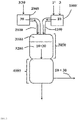
- the workup part ( 5000 ) can be subdivided into facilities for the recovery and recycling of unreacted phosgene (and for the separation of the coupled product hydrogen chloride) ( 5100 ) and in facilities for recovering the produced isocyanate in pure form (and possibly for the recovery of inert solvent) ( 5200 ) ,
- the processing part is in FIG. 1 indicated only schematically without the details listed below.
- the workup part ( 5000 ) in the devices 5100 comprises a washout column ( 5110 ) for removing isocyanate from the vapors ( 50 ) of the reaction termination zone ( 4000 ) by washing with an inert solvent, a phosgene absorption column ( 5120 ) for recovering phosgene from the Vapors of the washout column ( 5110 ) by absorption in an inert solvent, whereby hydrogen chloride and inerts ( 70 ) are separated from the phosgene, a phosgene absorption column ( 5130 ) for the separation of phosgene and inert solvent, and in the means 5200 a solvent column ( 5210 ) in particular for Separation of low-boiling components (in particular inert Solvent from the reaction termination zone ) from the crude isocyanate, a fine purification column ( 5220 ), in particular for the separation of high boilers (eg polyurea-containing residues) from the pre-purified
- the gaseous phosgene obtained is fed via the device 1100 to the mixing zone, while the separated inert solvent is preferably passed into the washout column ( 5110 ) and / or the phosgene absorption column (5120) .
- the compositions and mass flows of streams 10 and 20 are preferably coordinated so that in stream 10 phosgene ( 1 ) in a stoichiometric excess with respect to the primary amino groups of the amine ( 2 ) in stream 20 of at least 150% of theory, more preferably 160% to 350% of theory, and most preferably 170% to 300% of theory.
- one mole of phosgene reacts with one mole of amino groups, ie, theoretically, two moles of phosgene react with one mole of a diamine.
- the gaseous phosgene stream ( 10 ) may contain, in addition to phosgene ( 1 ), an inert substance ( 3 ).
- Inventive inert materials ( 3 ) are next to such substances that are already gaseous at room temperature and atmospheric pressure, such as nitrogen, helium or argon, and the vapors of inert organic solvents which are liquid at room temperature and atmospheric pressure, eg. As aromatic hydrocarbons, optionally with halogen substitution, such as. As chlorobenzene or dichlorobenzene (all isomers, preferably ortho- dichlorobenzene). Nitrogen is particularly preferably used for diluting the phosgene.
- the proportion of inert material ( 3 ) in the phosgene gas stream ( 10 ) can be selected as usual in the prior art.
- the gaseous amine stream ( 20 ) in addition to amine ( 2 ) still contain an inert material ( 3 ).
- the same inert substances ( 3 ) as described above for the phosgene gas stream ( 10 ) are possible. If both streams ( 10 and 20 ) contain an inert substance ( 3 ), the same inert substance ( 3 ) is preferably used.
- the operation of the gas phase phosgenation plant ( 100 ) at a desired value for the desired mass flow M ' target ( 2 ) can be carried out according to a method known from the prior art.
- the reaction mixture produced in the mixing zone ( 3100 ) is preferably passed continuously through the reaction zone ( 3200 ) while avoiding backmixing and preferably at a temperature of 200 ° C. to 600 ° C. and an absolute pressure of 80 mbar to 2,500 mbar within a average contact time of 0.05 to 15 seconds adiabatically or isothermally, preferably adiabatically, converted to a gaseous process product containing the desired isocyanate ( 4 ).
- Suitable embodiments are in EP 2 196 455 B1 and EP 1 935 876 B1 described.
- the gaseous process product ( 40 ) emerging from the reaction zone ( 3200 ) is rapidly cooled. This is preferably done by contacting with an inert solvent whose temperature is kept below the boiling point of the isocyanate ( 4 ) and above the decomposition temperature of the carbamic acid chloride corresponding to the reacted amine.
- Suitable embodiments are in EP 1 935 875 B1 described.
- uncondensed isocyanate ( 4 ) in this step is preferably separated off from the gaseous mixture remaining in the reaction termination zone by washing with a scrubbing liquid and preferably combined with the condensate ( 60 ) obtained in the reaction termination zone ( 4000 ).
- a suitable embodiment is in EP 1 935 875 B1 in particular in paragraphs [0024] and [0025].
- the desired isocyanate ( 4 ) is isolated by distillation from the thus obtained crude liquid process product ( 60 ).
- Suitable embodiments are known in the art and, for example, in WO 2013/139703 .
- step (I) of the process according to the invention the shutdown of the amine feed takes place in the mixing and reaction zone. This is done by reducing the registered in the device 2000 Amine mass flow M '( 2 ) of the value M' target ( 2 ) to zero. This reduction takes place steplessly or in stages, preferably continuously.
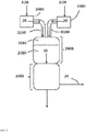
- an inert gas stream ( 30 ) is maintained through means 2100, mixing zone ( 3100 ), reaction zone ( 3200 ) and reaction termination zone ( 4000 ) (see also US Pat FIG. 2 ).
- the inert gas stream ( 30 ) consists of at least one inert substance ( 3 ), the same inert substances are suitable, as described above for the optional dilution of the phosgene in the gas stream ( 10 ).
- This inert gas stream ( 30 ) preferably has a temperature above the dew point of the amine ( 2 ) under the present pressure conditions. However, the temperature is preferably not so high that thermal decomposition of the starting materials or products still present in the apparatus would be to be feared.
- a temperature in the range from 200 ° C. to 600 ° C., particularly preferably in the range from 200 ° C. to 500 ° C. and very particularly preferably in the range from 250 ° C. to 500 ° C. is preferred.
- the maintenance of the inert gas stream ( 30 ) in step (I) can be done by ( a ) an inert material ( 3 ), preferably liquid at room temperature and normal pressure, having a temperature T 3 which is lower than that for the inert gas stream ( 30 ) in step (I ) target temperature (ie, preferably less than 200 ° C) is introduced into the device 2000 , heated there and then passed into the device 2100 and the other parts to be inerted plant parts.
- target temperature ie, preferably less than 200 ° C
- the inert gas stream ( 30 ) is provided in the device 2000 .
- This embodiment is particularly advantageous when the reaction mixture is diluted during the reaction in normal operation with the vapors of an inert material ( 3 ) present in liquid form at room temperature and normal pressure.
- inert substance ( 3 ) it is possible to introduce the inert substance ( 3 ) into the device 2000 in liquid form and to evaporate there first.
- inert substances ( 3 ) are inert solvents such as aromatic hydrocarbons, optionally with halogen substitution, such as.
- chlorobenzene or Dichlorobenzene all isomers, preferably ortho- dichlorobenzene.
- the inert substance ( 3 ) is heated (ie vaporized upon entry as liquid) to give an inert gas stream ( 30 ) having a temperature T 30 of preferably 200 ° C to 600 ° C, more preferably 200 ° C to 500 ° C and most preferably 250 ° C to 500 ° C, and an absolute pressure p 30 of preferably 100 mbar to 3,000 mbar, more preferably 150 mbar to 2,800 mbar and most preferably 200 mbar to 2,500 mbar.
- the streams ( 3 ) and ( 30 ) do not differ in their chemical composition, but only in temperature and possibly pressure.
- inert gas stream ( 30 ) having a temperature T 30 of preferably 200 ° C to 600 ° C, more preferably 200 ° C to 500 ° C and most preferably 250 ° C to 500 ° C ° C, and an absolute pressure p 30 of preferably 100 mbar to 3000 mbar, more preferably 150 mbar to 2800 mbar and most preferably 200 mbar to 2500 mbar, initiate and from there into the device 2100 and the other parts to be inerted to be transferred , It is also possible in this embodiment to further heat the introduced inert gas stream ( 30 ) in the device 2000 within the previously defined temperature ranges.
- the inert gas stream ( 30 ) can also be fed directly into the device 2100 .
- the pipeline between the device 2000 and the mixing zone (3100) forming part of the device 2100 is closed, more preferably immediately behind the device 2000.
- variant (A) no matter in which embodiment, is particularly advantageous when the reaction mixture is diluted during the reaction in the normal operation with an already gaseous at room temperature and atmospheric pressure inert material such as nitrogen, helium or argon.
- the pressure in the apparatus 2000 P 2000 by feeding the Inertstoffstroms (30) is adjusted to a value preferably lying above the pressure p 3100 in the mixing zone (3100) .
- the value for p 3100 is preferably 80 mbar (absolute) to 2,500 mbar (absolute), while the value p 2000 is preferably 100 mbar (absolute) to 3,000 mbar (absolute).
- step (II) of the method according to the invention the mass flow of phosgene M '( 1 ) leaving the device 1000 is reduced from the value M' target (1) to zero. This is done continuously or in stages, preferably continuously. Step (II) becomes particularly preferred only after a lapse of a period of at least 10 times the residence time, preferably at least 30 times the residence time at least 60 times the residence time, most preferably at least 90 times the residence time, of phosgene ( 1 ) leaving the device 1000 to exit from the reaction termination zone ( 4000 ) during normal operation of the gas phase phosgenation plant ( 100 ), calculated from the time of from which M ' (2) is zero.
- a gaseous inert gas stream ( 30 ) through the device 1100, the mixing zone ( 3100 ), the reaction zone ( 3200 ) and the reaction termination zone ( 4000 ) is maintained (see also FIG. 3 ).
- the inert gas stream ( 30 ) consists of at least one gaseous inert material ( 3 ), wherein the same inert substances are suitable, as described above for the optional dilution of the phosgene in the gas stream ( 10 ).
- the maintenance of the inert gas stream ( 30 ) in step (II) can be done by ( a ) an inert material ( 3 ), preferably liquid at room temperature and normal pressure, having a temperature T 3 which is lower than that for the inert gas stream ( 30 ) in step (II ) target temperature is introduced into the device 1000 , heated there and then passed into the device 1100 and the other parts of the system to be inerted.
- the temperature of the inert gas stream ( 30 ) of step (II) is from 200 ° C to 600 ° C, more preferably from 200 ° C to 500 ° C, and most preferably from 250 ° C to 500 ° C.
- inert substance ( 3 ) is inert solvents such as aromatic hydrocarbons, optionally with halogen substitution, such as.
- inert solvents such as aromatic hydrocarbons, optionally with halogen substitution, such as.
- chlorobenzene or dichlorobenzene all isomers, preferably ortho- dichlorobenzene.
- the inert substance ( 3 ) is heated (ie evaporated when introduced as a liquid) to give an inert gas stream ( 30 ) having a temperature T 30 of preferably 200 ° C to 600 ° C, more preferably 200 ° C to 500 ° C and most preferably 250 ° C to 500 ° C, and an absolute pressure p 30 of preferably 100 mbar to 3,000 mbar, more preferably 150 mbar to 2,800 mbar and most preferably 200 mbar to 2,500 mbar.
- the streams ( 3 ) and ( 30 ) do not differ in their chemical composition, but only in temperature and possibly pressure.
- step (I) is carried out according to variant (a), it is preferred to also carry out step (II) according to variant (a).
- an inert gas stream ( 30 ) having a temperature T 30 of preferably 200 ° C to 600 ° C, more preferably 200 ° C to 500 ° C and most preferably 250 ° C to 500 ° C ° C, and an absolute pressure p 30 of preferably 100 mbar to 3,000 mbar, more preferably 150 mbar to 2,800 mbar and most preferably 200 mbar to 2,500 mbar, to initiate. It is also possible in this embodiment to further heat the introduced inert gas stream ( 30 ) in the device 1000 within the previously defined temperature ranges. Alternatively, the inert gas stream ( 30 ) may also be fed directly into the device 1100 .
- Variant (b) no matter in which embodiment, is particularly advantageous when the reaction mixture is diluted during the reaction in normal operation with an inert material such as nitrogen, helium or argon already present in gaseous form at room temperature and atmospheric pressure. If step (I) is carried out according to variant (b), it is preferred to also carry out step (II) according to variant (b).
- step (II) only after a period of at least 10 times the residence time, preferably at least 30 times the residence time, more preferably at least 60 times the residence time, most preferably at least 90 times the residence time of phosgene ( 1 ) from the exit from the device 1000 to the exit from the reaction termination zone ( 4000 ) in the regular operation of the gas phase phosgenation plant ( 100 ), calculated from the time from which M ' (2) is zero, causes residual amounts of unreacted amine ( 2 ) can be phosgenated.
- steps (I) and (II) are preferably within less than 12 hours, preferably within less than 6 hours, more preferably within less than 3 hours, and all most preferably carried out in less than 1 hour.
- Inert gas flows (30) of identical composition are preferably used in steps (I) and (II).
- the inert gas stream ( 30 ) from (I) is maintained (III) for at least a period which is three times, preferably 100 times, more preferably 200 times, most preferably 350 times, the residence time of the inert gas stream ( 30 ). from entry into the mixing zone ( 3100 ) to exit from the reaction termination zone ( 4000 ), from the time when the mass flow of phosgene M '( 1 ) leaving the apparatus 1000 is zero.
- the inert gas stream from (II) is also maintained during this process, in which case the residence time of the combined inert gas streams from (I) and (II) is decisive. Following step (III), it may be possible - after cooling - to open system parts for maintenance work.
- the inert gas streams ( 30 ) from steps (I) and (II) are preferably discharged after exit from the reaction termination zone ( 4000 ) or, if present, preferably after passing through at least parts of the reprocessing devices 5100, via an exhaust gas discharge.
- the inert gas streams ( 30 ) from steps (I) and (II) preferably pass through the above-described apparatus washout column ( 5110 ) and phosgene absorption column ( 5120 ) and are subsequently discharged.
- reaction zones ( 3200 ) are to be operated in parallel, it is preferred, but not mandatory, to take them out of operation in succession as described above.
- the ancillary systems such as the HCl absorption, phosgene absorption, if necessary, solvent work-up or also the exhaust gas treatment) must be dimensioned so that the quantities of inert gas streams ( 30 ) required for the shutdown can be handled.
- Phosgene can flow into the device 2100 (preferably Amindüse) and it can lead to blockages, caking with polyurea, etc.
- desired phosgene excess in the continuous production at desired mass flow M ' target ( 2 ) is at least significantly undershot, at least for a short time, whereby by-products are formed because the flow equilibria are disturbed and uncontrolled mixing occurs.
- the residence time of the educts in the reaction space is disturbed if both reactant streams are switched off at the same time.
- the process of the present invention enables smooth reconnection of the plant and subsequent workup of the resulting crude isocyanate in a technically smooth manner with reduced or, ideally, no downtime with directly high end product quality. Elaborate cleaning work during a standstill can be avoided or at least reduced in scope.
- Ingredients in ppm or% are mass fractions based on the total mass of the respective substance (s).
- Toluene diamine (TDA) ( 2 ) is continuously evaporated in an amine evaporator ( 2000 ) together with nitrogen ( 3 ).
- the residence time of the TDA stream ( 20 ) from leaving the evaporator ( 2000 ) to the exit from the Amindüse is 5 seconds.
- the phosgene used is a mixture of fresh phosgene ( 1 ') and phosgene ( 1 " ) recovered in the working-up section ( 5000 ), mixing the two starting materials well and avoiding backmixing
- the temperature of the gaseous TDA stream ( 20 ) Nozzle mouth is 380 ° C (TDA has about 1 second residence time at this temperature in the inlet to the nozzle mouth.)
- the gaseous phosgene ( 10 ) has a temperature of 320 ° C when leaving the phosgene rectifier, wherein the residence time of the hot phosgene between last phosgene superheater and
- the gaseous mixture of streams ( 10 ) and ( 20 ) has a residence time of 8 seconds in the gas phase reactor ( 3000 ) and reacts at an absolute pressure of 1,692 mbar to form a gaseous reaction mixture ( 40 ).
- 4000 comprises a two-stage "quench” in which the gaseous reaction mixture ( 40 ) by spraying Ortho-dichlorobenzene (ODB) is cooled to 168 ° C, so that it condenses and in the sump ( 4100 ) a mixture ( 60 ) of crude TDI and ODB accumulates.
- ODB Ortho-dichlorobenzene
- Excess phosgene, formed in the reaction of hydrogen chloride and inert are largely degassed under these conditions from the bottom tank ( 4100 ), the entrainment of TDI is reduced by means of internals.
- This process residual gas stream ( 50 ) is used to recover entrained TDI, phosgene and hydrogen chloride, as in WO 2011/003532 , Page 11, lines 24 to 25 described, worked up ( 5100 ).
- the mixture ( 60 ) from the sump tank ( 4100 ) becomes, as in EP 1 413 571 B1 worked up ( 5200 ), wherein TDI ( 4 ) is obtained in a flow rate of 15.6 t / h.
- TDI ( 4 ) typically has a purity of> 99.97% (gas chromatography, GC), a residual solvent content of ODB of ⁇ 5 ppm (GC), a residual chlorine content of hydrolyzable chlorine of ⁇ 10 ppm (titration according to ASTM D4663), an acidity of bound chlorine ⁇ 5 ppm (titration according to ASTM D5629), and the color number, measured as a number of hazards, is ⁇ 15 (determined according to DIN EN ISO 6271).
- Comparative Example 1 Decommissioning of a Gas-Phase Phosgenation Plant (100) by Switching Off the Supply of Phosgene Before the Amine Supply
- a gas phase phosgenation plant ( 100 ) is operated at a production capacity of 15.6 t / h TDI as described in the general conditions for the production of TDI and then taken out of service as follows:
- the phosgene supply is interrupted while the amine supply is maintained for about 2 minutes.
- the amine TDA is no longer completely phosgenated during this time and the resulting intermediates and by-products clog the mixing zone ( 3100 ), the reaction zone ( 3200 ) and the subsequent reaction quench zone ("quench", 4000 ).
- the differential pressure of entry of the educts TDA gas stream ( 20 ) and phosgene gas stream ( 10 ) into the phosgenation reactor ( 3000 ) via the vapor gas outlet of the bottom of the reaction termination zone ( 4000 ) to the TDI wash column ( 5110 ) increases within the short time during the phosgene gas stream ( 10 ) was interrupted and the amine gas stream ( 20 ) continued to run (about 2 minutes) to 913 mbar instead of 10 mbar during normal operation. Cleaning the reactor and its periphery must be done before it can be restarted.
- Comparative Example 2 Decommissioning of a Gas Phase Phosphorization Plant (100) with Simultaneous Stopping of the Amine and Phosgene Feed
- the gas-phase plant ( 100 ) is operated at a production capacity of 15.6 t / h TDI as described in the general conditions for the production of TDI and then taken out of service as follows:
- the phosgene generator is turned off. Thereafter, the amine and phosgene feed to the phosgenation reactor ( 3000 ) are simultaneously interrupted. Subsequently, the phosgenation reactor (3000) is rendered inert with nitrogen until the phosgenation reactor and its piping periphery are freed from educts and product.
- the amine evaporator including downstream heat exchanger ( 2000 ) and the devices 2100 including the Amindüse be exposed to nitrogen, with a temperature of 380 ° C is set.
- the phosgenation reactor ( 3000 ) is educt-free and product-free and rendered inert with hot nitrogen.
- the amine evaporation in the amine evaporator is started so that TDA evaporates at 300 ° C.
- the TDA is gradually heated in other heat exchangers to 380 ° C and injected as a gaseous TDA stream ( 20 ) of a pressure of 1,691 mbar (absolute) through the Amindüse in the Phosgenierreaktor ( 3000 ).
- the Phosgenweg is opened, and a phosgene gas stream ( 10 ) with a mass flow of 61 t / h and a temperature of 320 ° C and a pressure of 1691 mbar (absolute) at the reactor inlet into the phosgenation reactor ( 3000 ) injected.
- the system reaches the control mode state after 45 minutes.
- the system After 7 days, the system must be shut down because the differential pressure of entry of the reactants TDA gas stream ( 20 ) and phosgene gas stream ( 10 ) in the phosgenation reactor ( 3000 ) on the vapor outlet at the bottom of the reaction termination zone ( 4000 ) to the TDI wash column ( 5110 ) over time to 793 mbar, instead of 10 mbar in normal operation, has risen, and the energy needed to vaporize phosgene and TDA and transfer of the gas streams ( 10 ) and ( 20 ) in the Phosgenierreaktor ( 3000 ) are hardly applied can (the boiling temperature of the TDA ( 2 ) limits the evaporator capacity with increasing pressure).
- polyurea-containing massive deposits are found at the outlet of the amine nozzle, along the surface of the reactor space and on the surfaces of the quench.
- a gas phase production plant ( 100 ) is operated at a production capacity of 15.6 t / h TDI as described in the general conditions for the production of TDI and then taken out of service as follows:
- the amine feed to the phosgenation reactor ( 3000 ) is stopped by closing the reactant-carrying line (part of the 2100 device) behind the amine evaporator ( 2000 ).
- An inert gas purge of the device 2100 is not performed.
- the phosgene generator is turned off, thus interrupting the supply of fresh phosgene ( 1 ').
- the phosgene cycle is shut down by the supply of recycled material -Phosgen (1 ") to the phosgenation reactor (3000) is interrupted. then, the phosgenation reactor (3000) is rendered inert with nitrogen.
- a phosgene cycle is established by recycling recycle phosgene ( 1 " ) from the workup ( 5100 ) of the vapors ( 50 ) of the reaction termination zone ( 4000 ) at a temperature of 320 ° C via the phosgenation reactor ( 3000 ), the reaction termination zone ( 4000 ) is moved back to the work-up. in the reaction termination zone (4000) during which only the (in the direction of flow of the reaction mixture 40) second quench in operation, so that the phosgene stream is cooled. in this Phosgen Vietnameselauf 61 t / h of phosgene are circulated. the loop 2100 including the Amindüse during its purged with a nitrogen gas stream (30).
- the amine evaporation is started by to 220 ° C pre-heated, liquid TDA (2) together with nitrogen in the amine evaporator (2000) is driven there, with the aid of a heat exchanger at 300 ° C and then evaporated with e is heated in a further heat exchanger at 410 ° C.
- the resulting TDA stream ( 20 ) is injected at an absolute pressure of 1654 mbar through the amine nozzle into the phosgenation reactor ( 3000 ).
- the amount of TDA ( 2 ) introduced into the phosgenation reactor ( 3000 ) during the start-up of the gas phase phosgenation unit ie, until the amine mass flow M'Soll ( 2 ) is reached, which is the case after 45 minutes) is infinitely variable 0 t / h increased to 12 t / h, the operating pressure in the phosgenation reactor ( 3000 ) at the end of commissioning is 1641 mbar (absolute).
- the first quencher in the flow direction of the reaction mixture ( 40 ) is put into operation shortly before the TDA gas stream ( 20 ) leaves the amine nozzle in the direction of the phosgenation reactor ( 3000 ) during commissioning.
- the phosgene consumed after the start of the plant is replaced by a mixture of fresh phosgene ( 1 ' ) and phosgene ( 1 ") recovered in the workup After 15 minutes 15.6 t / h of TDI ( 4 ) leave the last distillation column of workup stage.
- the gas phase phosgenation plant ( 100 ) is operated at a production capacity of 15.6 t / h TDI as described in the general conditions for the production of TDI and taken out of service as follows:
- the amine feed to the phosgenation reactor ( 3000 ) is stopped by closing the reactant-carrying line (part of the 2100 device) behind the amine evaporator ( 2000 ). Meanwhile, a gaseous nitrogen flow through the device 2100, the mixing zone (3100), the reaction zone (3200), the termination of the reaction zone (4000) and parts of the device 5100 (5120 Auswaschkolonne and Phosgenabsorptionskolonne 5120, both in FIG. 1 not shown) (step (I) of the method of the invention).
- the phosgene generator After reduction of the amine mass flow M '( 2 ) to zero, the phosgene generator is turned off, thus interrupting the supply of fresh phosgene ( 1' ) (step (II.a) of the process according to the invention).
- step (II.a) of the process according to the invention After 30 seconds (corresponding to about 4 times the residence time of phosgene (1) from exit from the device 1000 to exit from the reaction termination zone ( 4000 ) in the regular operation of the gas phase phosgenation (100)) the phosgene cycle is shut down by the supply of recycled material -Phosgen (1 ") to the phosgenation reactor (3000) is discontinued (step (II.b) of the process according to the invention).
- the device 1100, the reactor (3000), the termination of the reaction zone (4000) and parts of the device 5100 (Auswaschkolonne 5120 and Phosgenabsorptionskolonne 5120, both in FIG. 1 not shown) with nitrogen, which leaves the device 5100 by discharge from the phosgene absorption column ( 5120 ).
- the nitrogen streams from steps (I), (II.a) and (II.b) are after interruption of the phosgene cycle for 1 hour (corresponding to about 400 times the residence time of the combined inert gas streams ( 30 ) of entry into the mixing zone ( 3100 ) until exit from the reaction termination zone (4000)) (step (III) of the process according to the invention), after which the phosgenation reactor (3000) is freed from the educts and product.
- the operating pressure in the phosgenation reactor (3000) is 1651 mbar (absolute).
- the system must be turned off because the differential pressure of entry of the educts TDA gas stream (20) and phosgene gas stream ( 10 ) in the phosgenation reactor ( 3000 ) on the vapor outlet at the bottom of the reaction termination zone ( 4000 ) to the TDI wash column ( 5110 ) over time to 803 mbar, instead of 10 mbar in normal operation, has risen, and the energy needed to evaporate phosgene and TDA and transfer of the gas streams ( 10 ) and ( 20 ) in the Phosgenierreaktor ( 3000 ) are hardly applied can (the boiling temperature of the TDA ( 2 ) limits the evaporator capacity with increasing pressure).
- polyurea-containing massive deposits are found at the outlet of the amine nozzle, along the surface of the reactor space and on the surfaces of
- the gas phase phosgenation plant ( 100 ) is operated at a production capacity of 15.6 t / h TDI as described in the general conditions for the production of TDI and taken out of service as follows:
- the amine feed to the phosgenation reactor ( 3000 ) is stopped by closing the reactant-carrying line (part of the 2100 device) behind the amine evaporator ( 2000 ). Meanwhile, a gaseous nitrogen flow through the device 2100, the mixing zone (3100), the reaction zone (3200), the termination of the reaction zone (4000) and parts of the device 5100 (5120 Auswaschkolonne and Phosgenabsorptionskolonne 5120, both in FIG. 1 not shown) (step (I) of the method of the invention).
- step (II.a) of the process according to the invention After reduction of the amine mass flow M ' (2) to zero, the phosgene generator is turned off, thus interrupting the supply of fresh phosgene (1') (step (II.a) of the process according to the invention). After 15 minutes (corresponding to approximately 112 times the residence time of phosgene ( 1 ) from the outlet from the device 1000 to exit from the reaction termination zone ( 4000 ) in the regular operation of the gas phase (100) ) the phosgene cycle is shut down by the supply of recycled material -Phosgene ( 1 " ) to the phosgenation reactor ( 3000 ) is interrupted (step (II.b) of the invention Procedure).
- the nitrogen streams from steps (I), (II.a) and (II.b) are after interruption of the phosgene cycle for 1 hour (corresponding to about 400 times the residence time of the combined inert gas streams ( 30 ) of entry into the mixing zone ( 3100 ) until leaving the reaction termination zone (4000)) (step (III) of the process according to the invention), after which the phosgenation reactor ( 3000 ) is freed from the educts and product.
- Example 5 no blocking of the Amindüse and no formation of deposits in the Phosgenierreaktor are observed during decommissioning.
- the system can be put back into operation without problems and operated over a further phosgenation cycle of several months.
- the formation of unwanted by-products such as polyureas etc. is significantly reduced and the starting material is of high quality so that it does not have to be blended with TDI produced at a later date.
Landscapes
- Chemical & Material Sciences (AREA)
- Organic Chemistry (AREA)
- Chemical Kinetics & Catalysis (AREA)
- Organic Low-Molecular-Weight Compounds And Preparation Thereof (AREA)
Description
Die Erfindung betrifft ein Verfahren zum Betreiben einer Gasphasenphosgenierungsanlage (100) zur Umsetzung eines Amins (2) mit Phosgen (1) zum korrespondierenden Isocyanat (4), bei dem zur Außerbetriebnahme der Gasphasenphosgenierungsanlage (100) zunächst der Aminstrom abgestellt und der Phosgenstrom noch aufrechterhalten wird. Frühestens nach Verstreichen eines Zeitraums, welcher der 10-fachen, bevorzugt der 30-fachen, besonders bevorzugt der 60-fachen, ganz besonders bevorzugt der 90-fachen Verweilzeit von Phosgen (1) in den wesentlichen Teilen der Gasphasenphosgenierungsanlage (100) im Regelbetrieb derselben entspricht, gerechnet ab dem Zeitpunkt, ab dem der Aminzufluss vollständig abgestellt wurde, wird auch die Phosgenzufuhr abgestellt. Durch die Amin- und Phosgenzuführungseinrichtungen sowie durch alle anderen wesentlichen Teile der Gasphasenphosgenierungsanlage (100) wird während der Außerbetriebnahme ein Inertgasstrom (30) aufrechterhalten.The invention relates to a method for operating a gas phase phosgenation plant ( 100 ) for reacting an amine ( 2 ) with phosgene ( 1 ) to the corresponding isocyanate ( 4 ), in which the amine stream is shut off and the phosgene stream is maintained for decommissioning the gas phase phosgenation plant ( 100 ) , At the earliest after the lapse of a period which is 10 times, preferably 30 times, more preferably 60 times, most preferably 90 times, the residence time of phosgene ( 1 ) in the essential parts of the gas phase phosgenation plant ( 100 ) during normal operation thereof from the time when the amine feed was completely shut off, the phosgene supply is also turned off. Through the amine and phosgene feeders as well as through all other essential parts of the gas phase phosgenation plant ( 100 ) an inert gas stream ( 30 ) is maintained during decommissioning.
Isocyanate werden in großen Mengen hergestellt und dienen hauptsächlich als Ausgangsstoffe zur Herstellung von Polyurethanen. Ihre Herstellung erfolgt zumeist durch Umsetzung der entsprechenden Amine mit Phosgen, wobei Phosgen im stöchiometrischen Überschuss eingesetzt wird. Die Umsetzung der Amine mit dem Phosgen kann sowohl in der Gasphase als auch in der Flüssigphase erfolgen. Die Verfahrensführung in der Gasphase, üblicherweise als Gasphasenphosgenierung bezeichnet, zeichnet sich dadurch aus, dass die Reaktionsbedingungen so gewählt werden, dass zumindest die Reaktionskomponenten Amin, Isocyanat und Phosgen, bevorzugt jedoch sämtliche Edukte, Produkte und Reaktionszwischenprodukte, bei den gewählten Bedingungen gasförmig sind. Vorteile der Gasphasenphosgenierung sind u. a. ein verringertes Phosgenaufkommen (sog. Phosgen-"Hold-Up"), die Vermeidung schwer phosgenierbarer Zwischenprodukte, erhöhte Reaktionsausbeuten und ein geringerer Energiebedarf, da mit weniger Lösungsmittel gearbeitet wird. Die vorliegende Erfindung betrifft ausschließlich die Gasphasenphosgenierung und betrifft insbesondere ein reibungsloses Verfahren zur Inbetriebnahme einer Gasphasenphosgenierungsanlage.Isocyanates are produced in large quantities and serve mainly as starting materials for the production of polyurethanes. They are usually prepared by reacting the corresponding amines with phosgene, wherein phosgene is used in stoichiometric excess. The reaction of the amines with the phosgene can be carried out both in the gas phase and in the liquid phase. The procedure in the gas phase, commonly referred to as gas phase phosgenation, is characterized in that the reaction conditions are chosen so that at least the reaction components amine, isocyanate and phosgene, but preferably all starting materials, products and reaction intermediates, are gaseous at the selected conditions. Advantages of gas phase phosgenation include u. a. a reduced phosgene (so-called phosgene "hold-up"), the avoidance of difficult phosgenable intermediates, increased reaction yields and lower energy requirements, since working with less solvent. The present invention relates exclusively to gas phase phosgenation and more particularly relates to a smooth process for starting up a gas phase phosgenation plant.
Es sind aus dem Stand der Technik verschiedene Verfahren zur Herstellung von Isocyanaten durch Umsetzung von Aminen mit Phosgen in der Gasphase bekannt. Wichtig für eine gute Verfahrensführung ist eine gute Vermischung der Edukte der Gasphasenphosgenierung.
Die Optimierung des Einsatzes von Rohrreaktoren für die Gasphasenphosgenierung, wie er grundlegend in der
Nach der Lehre der
Wie in der
Gemäß der Lehre von
Eine Weiterentwicklung des Einsatzes von Rohrreaktoren für die Gasphasenphosgenierung ist Gegenstand von
In
In
In
Die Anmeldung lehrt, dass wesentliche Parameter einer Phosgenierung, wie insbesondere die Verweilzeiten der Reaktionspartner in den einzelnen Apparaten, für den Betrieb der Produktionsanlage bei Nennkapazität optimiert sind, was zu Problemen hinsichtlich Ausbeute und Produktreinheit führen kann, wenn die Anlage bei geringerer als Nennkapazität betrieben wird (vgl. S. 2, Z. 20 bis 36). Um die optimierten - engen - Verweilzeitfenster auch bei Teilauslastung (d. h. gegenüber Betrieb bei Nennkapazität verringertem Aminstrom) erreichen zu können, wird vorgeschlagen, entweder den Phosgenstrom und/oder den Inertenanteil zu erhöhen (vgl. S. 3, Z. 5 bis 19), und zwar bevorzugt so, dass der Gesamtmengenstrom aller Komponenten im Wesentlichen dem bei Nennkapazität entspricht (vgl. S. 6, Z. 4 bis 8). Die Anmeldung erwähnt zwar Abfahrprozesse in der Beschreibung des Hintergrunds der beanspruchten Erfindung auf S. 2, offenbart jedoch keinerlei technische Lehre zum konkreten Handeln, wie denn eine in Betrieb befindliche Produktionsanlage am vorteilhaftesten außer Betrieb genommen wird (d. h. Aminstrom und Phosgenstrom sind gleich null). Die in der Anmeldung offenbarten technischen Maßnahmen (d. h. die Erhöhung des Phosgenstroms und/oder des Inertenanteils) sind ausschließlich im Zusammenhang mit der Problematik des Betriebs einer Produktionsanlage bei geringerer als Nennkapazität bzw. mit der Problematik, wie eine bei Nennkapazität betriebene Anlage vorteilhafterweise auf den Betrieb (d. h. Amin- und Phosgenstrom sind signifikant größer als null) bei geringerer als Nennkapazität umgestellt werden kann (siehe die Beispiele), zu sehen.The application teaches that essential parameters of phosgenation, such as, in particular, the residence times of reactants in the individual apparatus, are optimized for the operation of the production plant at rated capacity, which can lead to problems in terms of yield and product purity when the plant is operated at less than rated capacity (see
Den beschriebenen Verfahren des Standes der Technik gelingt es zwar, eine Phosgenierung durchzuführen, ohne dass es bei den Endprodukten zu einer Qualitätseinbuße kommt, jedoch werden von wenigen Ausnahmen abgesehen nur solche Verfahren beschrieben, die sich im Normalbetrieb befinden. Der Abfahrprozess, also die sichere Außerbetriebnahme einer Gasphasenphosgenierungsanlage auf eine Art und Weise, welche eine reibungslose Wiederinbetriebnahme zu einem späteren Zeitpunkt ermöglicht, wird nicht beschrieben.Although the described prior art process succeeds in carrying out a phosgenation without any loss of quality in the end products, apart from a few exceptions, only those processes are described which are in normal operation. The Abfahrprozess, ie the safe decommissioning of a gas phase phosgenation plant in a manner that allows a smooth restart at a later date, is not described.
Dem Fachmann ist bekannt, dass ein kontinuierlich betriebener industrieller Prozess nicht ohne Not schlagartig außer Betrieb genommen werden sollte. Die Außerbetriebnahme (auch als Abfahren bezeichnet) einer Gasphasenphosgenierungsanlage ist ein im industriellen Alltag häufig auftretender Vorgang, der nicht zwangsläufig mit einem Öffnen oder einem anderen mechanischen Eingriff in die Phosgenieranlage verbunden sein muss. Das Abfahren zeichnet sich in der Praxis dadurch aus, dass es zu Abweichungen im Überschuss von Phosgen gegenüber Amin im Vergleich zum kontinuierlichen Betrieb bei der angestrebten Nennkapazität der Produktionsanlage kommen kann. Solche Abweichungen treten vor allen Dingen dann auf, wenn es z. B. durch Druckschwankungen zur Rückvermischung kommt. Dies ist insbesondere dann zu beobachten, wenn der aktuelle Mengenstrom an umzusetzendem Amin sehr klein ist im Vergleich zum angestrebten Mengenstrom an umzusetzendem Amin bei der angestrebten Nennkapazität der Anlage. Diese Mengenschwankungen im Verhältnis von Phosgen zu Amin sind nachteilig, da Feststoffe wie Polyharnstoff oder Aminhydrochloride ausfallen können. Darüber hinaus kann es bei nicht sachgemäßer Außerbetriebnahme zu unerwünschter Bildung von Tröpfchen an Amin kommen. Die Außerbetriebnahme einer Gasphasenphosgenierungsanlage ist daher ein kritischer Verfahrensschritt, da Fehler hierbei die spätere Wiederinbetriebnahme und die eigentliche kontinuierliche Produktion empfindlich stören können (bspw. durch Erhöhung des Differenzdrucks, welcher nötig ist, um eine ausreichende Strömung der Edukte und Produkte durch die Anlage zu gewährleisten).It is known to those skilled in the art that a continuously operated industrial process should not suddenly be shut down without emergency. The decommissioning (also referred to as shutdown) of a gas phase phosgenation plant is a frequently occurring in industrial everyday life process, which does not necessarily have to be associated with an opening or other mechanical intervention in the phosgenation. The departure is characterized in practice by the fact that it to deviations in excess of phosgene compared to amine compared to the continuous operation at the desired nominal capacity of the production plant can come. Such deviations occur above all things when it is z. B. comes due to pressure fluctuations for backmixing. This can be observed in particular when the actual mass flow of amine to be reacted is very small in comparison to the desired mass flow of amine to be reacted at the desired nominal capacity of the system. These volume fluctuations in the ratio of phosgene to amine are disadvantageous since solids such as polyurea or amine hydrochlorides can precipitate. In addition, if not properly decommissioned, undesirable formation of droplets of amine may occur. The decommissioning of a gas phase phosgenation plant is therefore a critical process step, since errors can disturb the later recommissioning and the actual continuous production sensitive (eg by increasing the differential pressure, which is necessary to ensure a sufficient flow of the reactants and products through the system) ,
Es bestand daher trotz der vielfältigen Fortschritte auf dem Gebiet der Gasphasenphosgenierung Bedarf an weiteren Verbesserungen. Diesem Bedarf Rechnung tragend ist ein Gegenstand der vorliegenden Erfindung ein Verfahren zum Betreiben einer Gasphasenphosgenierungsanlage (100) zur Umsetzung eines Amins (2) mit Phosgen (1) im stöchiometrischen Überschuss in Bezug auf die primären Aminogruppen des Amins (2) zum korrespondierenden Isocyanat (4), wobei die Gasphasenphosgenierungsanlage (100) mindestens
- (i) eine
Vorrichtung 1000 zur Bereitstellung eines gasförmigen Phosgenstroms (10), optional umfassend neben Phosgen (1) einen Inertstoff (3), - (ii) eine
Vorrichtung 2000 zur Bereitstellung eines gasförmigen Aminstroms (20), optional umfassend neben Amin (2) einen Inertstoff (3), - (iii) eine Mischzone (3100) zur Vermischung der
Ströme 10 und 20, wobei die Mischzone durch Einrichtungen (1100, 2100) jeweils mit derVorrichtung 1000 und derVorrichtung 2000 verbunden ist, - (iv) eine strömungstechnisch nach der Mischzone (3100) angeordnete Reaktionszone (3200) zur weiteren Umsetzung der zuvor
vermischten Ströme 10 und 20, - (v) eine strömungstechnisch nach der Reaktionszone (3200) angeordnete Reaktionsabbruchzone (4000) zur Beendigung der Umsetzung, und optional
- (vi) einen Aufarbeitungsteil (5000) umfassend Einrichtungen zur Rückgewinnung und Rückführung nicht umgesetzten Phosgens (1") (5100) und Einrichtungen zur Gewinnung des hergestellten Isocyanats in Reinform (5200)
bei dem im Regelbetrieb der Gasphasenphosgenierungsanlage (100) das Phosgen (1) im Phosgengasstrom (10) bevorzugt eine Mischung aus Frisch-Phosgen (1') und den Einrichtungen (5100) zurückgewonnenem Rezyklat-Phosgen (1") ist,
wobei
zur Außerbetriebnahme der Gasphasenphosgenierungsanlage (100) die folgenden Schritte durchlaufen werden:
- (I) Reduzierung des Amin-Massenflusses M'(2) auf null, wobei ein gasförmiger Inertgasstrom (30) durch die
Einrichtung 2100, die Mischzone (3100), die Reaktionszone (3200) und die Reaktionsabbruchzone (4000) aufrechterhalten wird; - (II) erst nach Verstreichen eines Zeitraums, der mindestens der 10-fachen Verweilzeit, bevorzugt mindestens der 30-fachen Verweilzeit, besonders bevorzugt mindestens der 60-fachen Verweilzeit, ganz besonders bevorzugt mindestens der 90-fachen Verweilzeit, von Phosgen (1) von Austritt aus der Vorrichtung 1000 bis Austritt aus der Reaktionsabbruchzone (4000) im Regelbetrieb der Gasphasenphosgenierungsanlage (100) entspricht, gerechnet ab dem Zeitpunkt, ab dem M'(2) null beträgt, Reduzierung des Massenflusses an Phosgen M'(1), welcher die
Vorrichtung 1000 verlässt, auf null, wobei ein gasförmiger Inertgasstrom (30) durch dieEinrichtung 1100, die Mischzone (3100), die Reaktionszone (3200) und die Reaktionsabbruchzone (4000) aufrechterhalten wird; - (III) Aufrechterhalten zumindest des Inertgasstroms (30) aus (I), bevorzugt der Inertgasströme (30) aus (I) und (II), mindestens für einen Zeitraum, welcher der dreifachen, bevorzugt mindestens der 100-fachen, besonders bevorzugt mindestens der 200-fachen, ganz besonders bevorzugt mindestens der 350-fachen, Verweilzeit des Inertgasstroms (30) von Eintritt in die Mischzone (3100) bis Austritt aus der Reaktionsabbruchzone (4000) entspricht, gerechnet ab dem Zeitpunkt, ab dem der Massenfluss an Phosgen M'(1), welcher die
Vorrichtung 1000 verlässt, null beträgt.
- (i) a
device 1000 for providing a gaseous phosgene stream ( 10 ), optionally comprising phosgene ( 1 ), an inert substance ( 3 ), - (ii) an
apparatus 2000 for providing a gaseous amine stream ( 20 ), optionally comprising in addition to amine ( 2 ) an inert substance ( 3 ), - (iii) a mixing zone ( 3100 ) for mixing the
streams apparatus 1000 and theapparatus 2000 , - (iv) a reaction zone ( 3200 ) arranged downstream of the mixing zone ( 3100 ) for further conversion of the previously
mixed streams - (v) a reaction termination zone ( 4000 ) arranged downstream of the reaction zone ( 3200 ) for terminating the reaction, and optional
- (vi) a work-up part ( 5000 ) comprising means for recovering and recycling unreacted phosgene ( 1 " ) ( 5100 ) and means for recovering the produced pure isocyanate ( 5200 )
in which the phosgene ( 1 ) in the phosgene gas stream ( 10 ) is preferably a mixture of fresh phosgene ( 1 ' ) and the recycled material ( 5100 ) recycled phosgene ( 1 ") in the regular operation of the gas phase phosgenation plant ( 100 ),
in which
to decommission the gas phase phosgenation plant ( 100 ), the following steps are taken:
- (I) reducing the amine mass flow M '( 2 ) to zero, maintaining a gaseous inert gas stream ( 30 ) through
means 2100, mixing zone ( 3100 ), reaction zone ( 3200 ) and reaction termination zone ( 4000 ); - (II) only after the lapse of a period of at least 10 times the residence time, preferably at least 30 times the residence time, more preferably at least 60 times the residence time, most preferably at least 90 times the residence time, of phosgene ( 1 ) of Exit from the
device 1000 until exit from the reaction termination zone ( 4000 ) during normal operation of the gas phase phosgenation plant ( 100 ), calculated from the time from which M '( 2 ) is zero, reducing the mass flow of phosgene M' ( 1 ), which theDevice 1000 exits to zero, maintaining a gaseous inert gas stream ( 30 ) throughdevice 1100, mixing zone ( 3100 ), reaction zone ( 3200 ), and reaction termination zone ( 4000 ); - (III) maintaining at least the inert gas stream ( 30 ) from (I), preferably the inert gas streams ( 30 ) from (I) and (II), at least for a period of time which is three times, preferably at least 100 times, more preferably at least the 200 times, more preferably at least 350 times, the residence time of the inert gas stream ( 30 ) from entry into the mixing zone ( 3100 ) to exit from the reaction termination zone ( 4000 ), calculated from the time from which the mass flow of phosgene M ' ( 1 ), which leaves the
device 1000 , is zero.
Unter einer Gasphasenphosgenierung ist erfindungsgemäß eine Verfahrensführung zur Phosgenierung von Aminen zu den korrespondierenden Isocyanaten zu verstehen, bei der die Amine im gasförmigen Zustand zu den Isocyanaten reagieren und im Verlauf der Reaktion sämtliche vorhandenen Komponenten (Edukte, Produkte, Zwischenprodukte, ggf. Nebenprodukte, ggf. Inertstoffe) während des Durchgangs durch die Reaktionszone zu mindestens 95,0 Massen-%, bevorzugt zu mindestens 98,0 Massen-%, besonders bevorzugt zu mindestens 99,0 Massen-%, ganz besonders bevorzugt zu mindestens 99,8 Massen-% und speziell zu mindestens 99,9 Massen-% jeweils bezogen auf die Gesamtmasse aller vorhandenen Komponenten, in der Gasphase verbleiben.According to the invention, a gas phase phosgenation is a process procedure for the phosgenation of amines to give the corresponding isocyanates, in which the amines react in the gaseous state to form the isocyanates and in the course of the reaction all components present (starting materials, products, intermediates, by-products, if appropriate Inert substances) during the passage through the reaction zone to at least 95.0% by mass, preferably at least 98.0% by mass, more preferably at least 99.0% by mass, most preferably at least 99.8% by mass and specifically to at least 99.9% by mass, in each case based on the total mass of all components present, remain in the gas phase.
Die Verweilzeit einer Komponente in einem Anlagenteil bezeichnet den Quotienten aus Volumenstrom der Komponente im Normzustand (angegeben als Vn /h, wobei Vn für m3 bei Normbedingungen steht ("Normkubikmeter")) und dem durchströmten Innenvolumen des betreffenden Anlagenteils (angegeben in m3). Ein Normkubikmeter Vn ist dabei diejenige Gasmenge, die bei
- einem Druck pn von 1,01325 bar,
- einer Luftfeuchtigkeit von 0 % (trockenes Gas) und
- einer Temperatur Tn von 273,15 K (tn = 0 °C) (Normbedingungen nach DIN 1343, STPD)
- a pressure p n of 1.01325 bar,
- a humidity of 0% (dry gas) and
- a temperature T n of 273.15 K ( t n = 0 ° C) (standard conditions according to DIN 1343, STPD)
Die in Schritt (II) relevante Verweilzeit des Phosgens (1) im Regelbetrieb der Gasphasenphosgenierungsanlage (100) ist eine rechnerische Größe, die aus dem bekannten Volumenstrom des Phosgens, das im Regelbetrieb die Vorrichtung 1000 verlässt (ohne evtl. vorhandenen Inertstoffanteil), und dem bekannten Innenvolumen der durchströmten Apparate inklusive der diese verbindenden Rohrleitungen ermittelt wird. In analoger Weise wird die in Schritt (III) relevante Verweilzeit des Inertgasstroms (30) rechnerisch ermittelt. Dabei wird der Volumenstrom an Inertgasstrom (30) zugrunde gelegt, welcher zu dem Zeitpunkt, an dem der Massenstrom M'(1), welcher die Vorrichtung 1000 verlässt, null erreicht, vorliegt. Dieser Inertgasstrom (30) besteht in der einfachsten Ausführungsform aus dem Inertgasstrom aus (I). Bevorzugt wird jedoch in (III) auch der Inertgasstrom aus (II) noch aufrechterhalten. In dieser letztgenannten Ausführungsform besteht der Inertgasstrom in (III) daher aus den vereinigten Inertgasströmen aus (I) und (II).The residence time of the phosgene ( 1 ) in step (II), which is relevant during normal operation of the gas phase phosgenation plant ( 100 ), is a mathematical variable which is calculated from the known volume flow of the phosgene leaving the
Geeignete Amine (2) sind dabei insbesondere Isophorondiamin, Hexamethylendiamin, Bis(p-aminocyclohexyl)methan, Toluylendiamin und Diphenylmethandiamin.Suitable amines ( 2 ) are in particular isophoronediamine, hexamethylenediamine, bis (p-aminocyclohexyl) methane, toluenediamine and diphenylmethanediamine.
Im Rahmen der vorliegenden Erfindung umfasst der Ausdruck "Außerbetriebnahme einer Gasphasenphosgenierungsanlage" alle Verfahrensschritte, die erforderlich sind, um eine in Betrieb befindliche Gasphasenphosgenierungsanlage (die mit einer zu einem bestimmten Zeitpunkt angestrebten Sollproduktion, ausgedrückt als angestrebter Massenfluss an umzusetzendem Amin, M'Soll(2) [z. B. t(Amin)/h], betrieben wird), außer Betrieb zu nehmen, beispielsweise um Wartungsarbeiten durchzuführen. Der Betrieb der Gasphasenproduktionsanlage (100) bei M'Soll(2) wird im Rahmen dieser Erfindung als Regelbetrieb bezeichnet. M'Soll(2) kann, muss aber nicht, dabei dem Wert von M'Soll(2) bei Nennkapazität M'Nenn(2) der Gasphasenproduktionsanlage (100) entsprechen. Die Nennkapazität einer Produktionsanlage wird in der Fachwelt in pro Jahr zu produzierender Tonnen an Produkt ("Jahrestonnen") angegeben, wobei alle planbaren Anlagenstillstände berücksichtigt werden.In the context of the present invention, the term "decommissioning of a gas phase phosgenation plant" encompasses all the process steps required for operating a gas phase phosgenation plant (which has a targeted production at a certain time, expressed as the targeted mass flow of amine to be reacted, M ' target ( 2 ) [eg, t (amine) / h] is operated), for example, to perform maintenance. The operation of the gas phase production plant ( 100 ) at M ' Soll ( 2 ) is referred to as a control operation in the context of this invention. M ' target ( 2 ) may, but need not, correspond to the value of M' target ( 2 ) at nominal capacity M ' nominal ( 2 ) of the gas phase production plant ( 100 ). The nominal capacity of a production plant is specified in the professional world in terms of per year to be produced tons of product ("annual tonnes"), taking into account all the planned plant downtimes.
Das Wort "ein" ist im Rahmen dieser Erfindung im Zusammenhang mit zählbaren Größen lediglich als unbestimmter Artikel und nur dann als Zahlwort zu verstehen, wenn dies ausdrücklich, etwa durch den Zusatz "genau ein", gesagt wird. Bspw. schließt der Ausdruck "eine Reaktionszone" die Möglichkeit des Vorhandenseins mehrerer (in Reihe oder parallel geschalteter) Reaktionszonen nicht aus.The word "a" is to be understood in the context of this invention in connection with countable quantities only as an indefinite article and only as a number word, if this is expressly said, for example by the addition "exactly one". For example. the term "one reaction zone" does not exclude the possibility of the presence of multiple (in series or parallel) reaction zones.
Erfindungsgemäß wesentlich ist, dass zur Außerbetriebnahme (zum "Abfahren") der Gasphasenphosgenierungsanlage (100) zunächst nur der Amin-Massenfluss M'(2) vom Wert M'Soll(2) auf null reduziert wird. Beim Abfahren wird das Amin immer vor dem Phosgen abgestellt, wodurch ein Rückvermischen von Amin in die Phosgenzuführungseinrichtungen verhindert und ein Überschuss an Phosgen gegenüber Amin auch während der Außerbetriebnahme der Gasphasenphosgenierungsanlage (100) sichergestellt wird. Durch das erfindungsgemäße Durchspülen der Aminzuführungseinrichtungen mit einem Inertgasstrom (30) wird ein Zurückströmen von Phosgen in die Aminzuführungseinrichtungen (Rückvermischung) verhindert. Das Durchspülen der Einrichtung 2100 (und bevorzugt auch der Einrichtung 1100), der Mischzone (3100), der Reaktionszone (3200) und der Reaktionsabbruchzone (4000) mit einem Inertgasstrom (30) wird frühestens nach einem Zeitraum eingestellt, welcher der dreifachen, bevorzugt der 100-fachen, besonders bevorzugt der 200-fachen, ganz besonders bevorzugt der 350-fachen Verweilzeit des Inertgasstroms (30) aus (I), in der bevorzugten Ausführungsform der vereinigten Inertgasströme (30) aus (I) und (II), von Beginn der Mischzone (3100) bis Austritt aus der Reaktionsabbruchzone (4000) entspricht, gerechnet ab dem Zeitpunkt, ab dem der Massenfluss an Phosgen M'(1), welcher die Vorrichtung 1000 verlässt, null beträgt.According to the invention, it is essential that for decommissioning (for "shutdown") of the gas phase phosgenation unit ( 100 ), initially only the mass flow M '( 2 ) of the value M' target ( 2 ) is reduced to zero. On shutdown, the amine is always shut off before the phosgene, thereby preventing backmixing of amine into the phosgene feeders and ensuring an excess of phosgene over amine even during the decommissioning of the gas phase phosgenation unit ( 100 ). By flushing the amine feed devices according to the invention with an inert gas stream ( 30 ), a backflow of phosgene into the amine feed devices (backmixing) is prevented. The purging of the device 2100 (and preferably also the device 1100 ), the mixing zone ( 3100 ), the reaction zone ( 3200 ) and the reaction termination zone ( 4000 ) with an inert gas stream ( 30 ) is set at the earliest after a period of time which is threefold, preferably 100 times, more preferably 200 times, most preferably 350 times the residence time of the inert gas stream ( 30 ) from (I), in the preferred embodiment of the combined inert gas streams ( 30 ) from (I) and (II), from the beginning of the mixing zone ( 3100 ) until it exits the reaction termination zone ( 4000 ), from the point in time when the mass flow of phosgene M '( 1 ) leaving the
Nachstehend werden die Schritte der Erfindung detailliert erläutert. Verschiedene Ausführungsformen sind dabei beliebig miteinander kombinierbar, solange sich für den Fachmann aus dem Kontext nicht eindeutig das Gegenteil ergibt.Hereinafter, the steps of the invention will be explained in detail. Various embodiments can be combined with one another as desired, as long as the opposite does not clearly result for the person skilled in the art from the context.
Erfindungsgemäß umfasst eine Gasphasenphosgenierungsanlage (100) mindestens die oben unter (i) bis (v) aufgeführten Einrichtungen (vgl. auch
- (i) Als Vorrichtung zur Bereitstellung eines gasförmigen Phosgenstroms (1000) kann grundsätzlich jede aus dem Stand der Technik bekannte, für die Überführung von Phosgen in die Gasphase geeignete, Vorrichtung verwendet werden. Bevorzugt erfolgt die Phosgengaserzeugung durch Destillation oder partielle Verdampfung in einer Destillationskolonne, wie in
DE102009032413A1 - (ii) Als Vorrichtung zur Bereitstellung eines gasförmigen Aminstroms (2000) kann grundsätzlich jede aus dem Stand der Technik bekannte, für die Überführung eines Amins in die Gasphase geeignete, Vorrichtung, wie dem Fachmann bekannte Verdampfungsapparaturen, verwendet werden. In einer bevorzugten Ausführungsform umfasst die
Vorrichtung 2000 eine Einrichtung zur Verdampfung und eine Einrichtung zur anschließenden Überhitzung des Amins (2). Ganz besonders bevorzugt sind mehrstufige Verdampfungs- und Überhitzungssysteme, in denen zwischen den Verdampfungs- und Überhitzungssystemen Tröpfchenabscheider eingebaut sind und/oder die Verdampfungsapparaturen auch die Funktion eines Tröpfchenabscheiders besitzen. Geeignete Tröpfchenabscheider sind z. B. beschrieben in "Droplet Separation", A. Bürkholz, VCH Verlagsgesellschaft, Weinheim - New York - Basel - Cambridge, 1989 - (iii) Der Aufbau einer erfindungsgemäß einsetzbaren Mischzone (3100) kann auf dem Fachmann bekannte Art und Weise erfolgen, bevorzugt wie in
EP-A-2 196 455 EP-A-1 935 876
- (i) As device for providing a gaseous phosgene stream (1000) it is possible in principle to use any device known from the prior art which is suitable for the conversion of phosgene into the gas phase. The phosgene gas production preferably takes place by distillation or partial evaporation in a distillation column, as in
DE102009032413A1 - (ii) As apparatus for providing a gaseous amine stream (2000), it is possible in principle to use any apparatus known from the prior art which is suitable for the conversion of an amine into the gas phase, such as evaporation apparatus known to the person skilled in the art. In a preferred embodiment, the
apparatus 2000 comprises means for evaporation and means for subsequent overheating of the amine ( 2 ). Very particular preference is given to multistage evaporation and overheating systems in which droplet separators are installed between the evaporation and overheating systems and / or the evaporation apparatuses also have the function of a droplet separator. Suitable droplet separators are z. As described in "Droplet Separation ", A. Bürkholz, VCH Verlagsgesellschaft, Weinheim - New York - Basel - Cambridge, 1989 - (iii) The construction of a mixing zone ( 3100 ) which can be used according to the invention can be carried out in a manner known to the person skilled in the art, preferably as in
EP-A-2,196,455 EP-A-1 935 876
Die Mischzone beginnt dort, wo im Regelbetrieb die Ströme (10) und (20) erstmals aufeinandertreffen. An dieser Stelle, auch als Eintritt in die Mischzone (3100) bezeichnet, vermischen sich während des Vorgangs der Außerbetriebnahme nach Einleitung von Schritt (II) die Inertgasströme aus (I) und (II) zu einem gemeinsamen Inertgasstrom, dessen Verweilzeit bis zum Austritt aus der Reaktionsabbruchzone (4000) die Grundlage für die Berechnung der Mindestdauer von Schritt (III) bildet.
- (iv) Die in der Mischzone (3100) erstmals aufeinandertreffenden Amin- und Phosgengasströme werden in einem Verweilzeitapparat, der Reaktionszone (3200), weiter umgesetzt. Mischzone (3100) und Reaktionszone (3200) können bevorzugt auch in einem einzigen Apparat, dem Reaktor (3000) vereinigt sein wie in
EP 2 196 455 A1
- (iv) The amine and phosgene gas streams meeting for the first time in the mixing zone ( 3100 ) are further reacted in a residence time apparatus, the reaction zone ( 3200 ) . The mixing zone ( 3100 ) and the reaction zone ( 3200 ) can preferably also be combined in a single apparatus, the reactor ( 3000 ) as in
EP 2 196 455 A1
Die Einrichtungen 1100 und 2100 , welche die Vorrichtungen zur Bereitstellung des gasförmigen Phosgen- (1000) bzw. Amingasstroms (2000) mit der Mischzone (3100) verbinden, sind erfindungsgemäß solche Einrichtungen, welche sich zur Überführung des jeweiligen Gasstroms (10) bzw. (20) aus den Vorrichtungen 1000 bzw. 2000 in die Mischzone (3100) eignen. Diese Einrichtungen umfassen neben Rohrleitungen zum Transport der Gasströme bevorzugt auch Düsenvorrichtungen, die eine intensive Durchmischung von Phosgengasstrom (10) und Amingasstrom (20) in der Mischzone (3100) gewährleisten. Es ist möglich, jeden der Gasströme (10) und (20) einzeln in die Mischzone (3100) einzudüsen. Bevorzugt ist jedoch eine Ausführungsform, in welcher die Rohrleitungen der Einrichtungen 1100 und 2100 in eine gemeinsame Düsenvorrichtung einmünden (in
- (v) Erfindungsgemäß einsetzbare Reaktionsabbruchzonen (4000) sind dem Fachmann bekannt. Bevorzugt ist eine Ausführungsform, wie sie in
EP 1 935 875 B1Vorrichtung 1000 verlässt, null beträgt. Besonders bevorzugt wird die Reaktionsabbruchzone erst nach einem Zeitraum, welcher mindestens der dreifachen, bevorzugt mindestens der 100-fachen, besonders bevorzugt mindestens der 200-fachen, ganz besonders bevorzugt mindestens der 350-fachen Verweilzeit des Inertgasstroms (30) von Eintritt in die Mischzone (3100) bis Austritt aus der Reaktionsabbruchzone (4000) entspricht, gerechnet ab dem Zeitpunkt, ab dem der Massenfluss an Phosgen M'(1), welcher dieVorrichtung 1000 verlässt, null beträgt.
- (v) Reaction termination zones (4000) which can be used according to the invention are known to the person skilled in the art. Preferred is an embodiment as shown in
EP 1 935 875 B1device 1000 is zero. Particularly preferably, the reaction termination zone is only after a period of at least three times, preferably at least 100 times, more preferably at least 200 times, most preferably at least 350 times the residence time of the inert gas stream ( 30 ) of entry into the mixing zone ( 3100 ) until exit from the reaction termination zone ( 4000 ), from the time point when the mass flow of phosgene M '( 1 ) leavingdevice 1000 is zero.
In einer besonders bevorzugten Ausgestaltung des erfindungsgemäßen Verfahrens wird das in der Reaktionsabbruchzone (4000) erhaltene Rohprodukt in derselben Gasphasenphosgenierungsanlage (100) aufgearbeitet, um das Isocyanat (4) aus dem flüssigen Gemisch (60) zu isolieren. In diesem Fall umfasst die Gasphasenphosgenierungsanlage (100) zusätzlich
- (vi) einen Aufarbeitungsteil (5000).
- (vi) a work-up part (5000) .
Geeignete Vorrichtungen zur Aufarbeitung sind in
Es ist möglich (in
Bei Betrieb der Gasphasenphosgenierungsanlage (100) mit dem angestrebten Soll-Massenfluss an umzusetzendem Amin von M'Soll (2) werden die Zusammensetzungen und Massenflüsse der Ströme 10 und 20 bevorzugt so aufeinander abgestimmt, dass in Strom 10 Phosgen (1) in einem stöchiometrischen Überschuss in Bezug auf die primären Aminogruppen des Amins (2) in Strom 20 von mindestens 150 % der Theorie, besonders bevorzugt 160 % bis 350 % der Theorie und ganz besonders bevorzugt 170 % bis 300 % der Theorie, vorliegt. Theoretisch reagiert ein Mol Phosgen mit einem Mol Aminogruppen, d. h., theoretisch reagieren zwei Mol Phosgen mit einem Mol eines Diamins. Der angestrebte Soll-Massenfluss M'soll (2) kann dabei der Nennkapazität der Gasphasenphosgenierungsanlage unter Zugrundelegung einer üblicher Anlagenverfügbarkeit entsprechen, d. h. der in einem bestimmten Zeitraum produzierten Menge an Isocyanat, für welche die Anlage konstruiert wurde (in der Regel als Tonnen pro Jahr angegeben). Wenn ungünstige Absatzbedingungen dies erforderlich machen, kann der angestrebte Soll-Massenfluss M'Soll(2) natürlich auch geringer sein. Dies ist für das erfindungsgemäße Verfahren nicht wesentlich. Beispielsweise ist es durchaus denkbar, das erfindungsgemäße Verfahren auf eine Gasphasenproduktionsanlage (100) anzuwenden, welche infolge eines schwierigen Marktumfelds zeitweise nur bei 50 % der Nennkapazität betrieben wird. Für die Dauer der schwierigen Marktsituation entspricht dann der Regelbetrieb der Produktion einem Amin-Massenfluss M'Soll(2) = 0,5 M'Nenn(2). When operating the gas phase phosgenation unit ( 100 ) with the desired target mass flow of amine to be reacted of M ' target (2) , the compositions and mass flows of
Der gasförmige Phosgenstrom (10) kann neben Phosgen (1) noch einen Inertstoff (3) enthalten. Erfindungsgemäß einsetzbare Inertstoffe (3) sind dabei neben solchen Stoffen, die bereits bei Raumtemperatur und Normaldruck gasförmig sind, wie Stickstoff, Helium oder Argon, auch die Dämpfe inerter organischer Lösungsmittel, die bei Raumtemperatur und Normaldruck flüssig sind, z. B. aromatische Kohlenwasserstoffe, ggf. mit Halogensubstitution, wie z. B. Chlorbenzol oder Dichlorbenzol (alle Isomere, bevorzugt ortho-Dichlorbenzol). Besonders bevorzugt wird Stickstoff zur Verdünnung des Phosgens eingesetzt. Der Anteil an Inertstoff (3) im Phosgengasstrom (10) kann dabei wie im Stand der Technik üblich gewählt werden.The gaseous phosgene stream ( 10 ) may contain, in addition to phosgene ( 1 ), an inert substance ( 3 ). Inventive inert materials ( 3 ) are next to such substances that are already gaseous at room temperature and atmospheric pressure, such as nitrogen, helium or argon, and the vapors of inert organic solvents which are liquid at room temperature and atmospheric pressure, eg. As aromatic hydrocarbons, optionally with halogen substitution, such as. As chlorobenzene or dichlorobenzene (all isomers, preferably ortho- dichlorobenzene). Nitrogen is particularly preferably used for diluting the phosgene. The proportion of inert material ( 3 ) in the phosgene gas stream ( 10 ) can be selected as usual in the prior art.
Ebenso kann der gasförmige Aminstrom (20) neben Amin (2) noch einen Inertstoff (3) enthalten. Hierbei sind die gleichen Inertstoffe (3), wie zuvor für den Phosgengasstrom (10) beschrieben, möglich. Enthalten beide Ströme (10 und 20) einen Inertstoff (3), so wird bevorzugt der gleiche Inertstoff (3) eingesetzt.Likewise, the gaseous amine stream ( 20 ) in addition to amine ( 2 ) still contain an inert material ( 3 ). In this case, the same inert substances ( 3 ) as described above for the phosgene gas stream ( 10 ) are possible. If both streams ( 10 and 20 ) contain an inert substance ( 3 ), the same inert substance ( 3 ) is preferably used.
Der Betrieb der Gasphasenphosgenierungsanlage (100) bei einem angestrebten Wert für den Soll-Massenfluss M'Soll(2) kann nach einem aus dem Stand der Technik bekannten Verfahren erfolgen. Bevorzugt wird hierzu das in der Mischzone (3100) erzeugte Reaktionsgemisch unter Vermeidung von Rückvermischung kontinuierlich durch die Reaktionszone (3200) geleitet und darin bevorzugt bei einer Temperatur von 200 °C bis 600 °C und einem absoluten Druck von 80 mbar bis 2.500 mbar innerhalb einer mittleren Kontaktzeit von 0,05 bis 15 Sekunden adiabat oder isotherm, bevorzugt adiabat, zu einem gasförmigen Verfahrensprodukt, enthaltend das gewünschte Isocyanat (4), umgesetzt. Geeignete Ausführungsformen sind in
In der Reaktionsabbruchzone (4000) wird das aus der Reaktionszone (3200) austretende, gasförmige Verfahrensprodukt (40), rasch abgekühlt. Bevorzugt geschieht dies durch Kontaktieren mit einem inerten Lösungsmittel, dessen Temperatur unterhalb der Siedetemperatur des Isocyanats (4) und oberhalb der Zersetzungstemperatur des dem umgesetzten Amin entsprechenden Carbaminsäurechlorids gehalten wird. Geeignete Ausführungsformen sind in
Im Anschluss wird aus dem so erhaltenen rohen flüssigen Verfahrensprodukt (60) das gewünschte Isocyanat (4) durch Destillation isoliert. Geeignete Ausführungsformen sind dem Fachmann bekannt und beispielsweise in
Die Hauptmenge des in der Reaktion nicht umgesetzten Phosgens verbleibt in der Gasphase (50), welche in der Reaktionsabbruchzone (4000) erhalten wird. Es ist bevorzugt, diese Gasphase in den Einrichtungen 5100 des bevorzugt vorhandenen Aufarbeitungsteils 5000 aufzuarbeiten, um dieses Phosgen rezyklieren zu können. Dieser Schritt ist aus dem Stand der Technik hinlänglich bekannt. Geeignete Ausführungsformen wurden weiter oben bereits beschrieben.The majority of the phosgene unreacted in the reaction remains in the gas phase ( 50 ) which is obtained in the reaction termination zone ( 4000 ). It is preferred to use this gas phase in the
Zur Außerbetriebnahme einer so betriebenen Gasphasenphosgenierungsanlage werden nun erfindungsgemäß die folgenden Schritte durchlaufen:
In Schritt (I) des erfindungsgemäßen Verfahrens erfolgt die Abschaltung der Aminzufuhr in die Misch- und Reaktionszone. Dies geschieht durch eine Reduzierung des in die Vorrichtung 2000 eingetragenen Aminmassenstroms M'(2) vom Wert M'Soll(2) auf null. Diese Reduzierung erfolgt stufenlos oder in Stufen, bevorzugt stufenlos.To decommission a gas-phase phosgenation plant operated in this way, the following steps are now carried out according to the invention:
In step (I) of the process according to the invention, the shutdown of the amine feed takes place in the mixing and reaction zone. This is done by reducing the registered in the
Während dieses Schrittes (I) wird ein Inertgasstrom (30) durch die Einrichtung 2100, die Mischzone (3100), die Reaktionszone (3200) und die Reaktionsabbruchzone (4000) aufrechterhalten (vgl. auch
Die Aufrechterhaltung des Inertgasstroms (30) in Schritt (I) kann geschehen, indem (a) ein bei Raumtemperatur und Normaldruck bevorzugt flüssig vorliegender Inertstoff (3) einer Temperatur T3, welche kleiner als die für den Inertgasstrom (30) in Schritt (I) angestrebte Temperatur (d. h. bevorzugt kleiner als 200 °C) ist, in die Vorrichtung 2000 eingeleitet, dort erhitzt und anschließend in die Einrichtung 2100 und die weiteren zu inertisierenden Anlagenteile geleitet wird. In der Variante (a) wird also der Inertgasstrom (30) in der Vorrichtung 2000 bereitgestellt. Diese Ausführungsform ist insbesondere dann vorteilhaft, wenn das Reaktionsgemisch während der Reaktion im Regelbetrieb mit den Dämpfen eines bei Raumtemperatur und Normaldruck flüssig vorliegenden Inertstoffs (3) verdünnt wird. Es ist möglich, den Inertstoff (3) flüssig in die Vorrichtung 2000 einzutragen und dort erst zu verdampfen. In der Variante (a) besonders geeignete Inertstoffe (3) sind inerte Lösungsmittel wie aromatische Kohlenwasserstoffe, ggf. mit Halogensubstitution, wie z. B. Chlorbenzol oder Dichlorbenzol (alle Isomere, bevorzugt ortho-Dichlorbenzol). In der Vorrichtung 2000 wird der Inertstoff (3) so erhitzt (d. h. bei Eintrag als Flüssigkeit verdampft), dass ein Inertgasstrom (30) erhalten wird, der eine Temperatur T30 von bevorzugt 200 °C bis 600 °C, besonders bevorzugt 200 °C bis 500 °C und ganz besonders bevorzugt 250 °C bis 500 °C, und einen absoluten Druck p30 von bevorzugt 100 mbar bis 3.000 mbar, besonders bevorzugt 150 mbar bis 2.800 mbar und ganz besonders bevorzugt 200 mbar bis 2.500 mbar, aufweist. Die Ströme (3) und (30) unterscheiden sich nicht in ihrer chemischen Zusammensetzung, sondern lediglich in Temperatur und ggf. Druck. Nachdem der in die Vorrichtung 2000 eingetragene Strom (3) erhitzt wurde, so dass er die Vorrichtung 2000 gasförmig verlässt, wird er als Strom (30) bezeichnet.The maintenance of the inert gas stream ( 30 ) in step (I) can be done by ( a ) an inert material ( 3 ), preferably liquid at room temperature and normal pressure, having a temperature T 3 which is lower than that for the inert gas stream ( 30 ) in step (I ) target temperature (ie, preferably less than 200 ° C) is introduced into the
Es ist (b) auch möglich, in die Vorrichtung 2000 direkt einen Inertgasstrom (30) einer Temperatur T30 von bevorzugt 200 °C bis 600 °C, besonders bevorzugt 200 °C bis 500 °C und ganz besonders bevorzugt 250 °C bis 500 °C, und eines absoluten Drucks p30 von bevorzugt 100 mbar bis 3.000 mbar, besonders bevorzugt 150 mbar bis 2800 mbar und ganz besonders bevorzugt 200 mbar bis 2500 mbar, einzuleiten und von dort in die Einrichtung 2100 und die anderen zu inertisierenden Anlagenteile zu überführen. Es ist in dieser Ausführungsform auch möglich, den eingeleiteten Inertgasstrom (30) in der Vorrichtung 2000 im Rahmen der zuvor definierten Temperaturbereiche weiter aufzuheizen. Alternativ kann der Inertgasstrom (30) auch direkt in die Einrichtung 2100 eingespeist werden. In dieser letztgenannte Ausführungsform wird bevorzugt nach Reduzierung des Massenflusses an Amin M'(2) auf null die Rohrleitung zwischen der Vorrichtung 2000 und der Mischzone (3100), welche Bestandteil der Einrichtung 2100 ist, geschlossen, insbesondere bevorzugt unmittelbar hinter der Vorrichtung 2000. Variante (a), egal in welcher Ausgestaltung, ist insbesondere dann vorteilhaft, wenn das Reaktionsgemisch während der Reaktion im Regelbetrieb mit einem bei Raumtemperatur und Normaldruck bereits gasförmig vorliegenden Inertstoff wie Stickstoff, Helium oder Argon verdünnt wird.It is also possible (b) to inject directly into the
Bis zur vollständigen Unterbrechung der Zufuhr von Amin (2) aus der Vorrichtung 2000 wird bevorzugt der Druck in der Vorrichtung 2000 p2000 durch Einspeisung des Inertstoffstroms (30) auf einen Wert eingestellt, der oberhalb des Drucks p3100 in der Mischzone (3100) liegt. Dabei beträgt der Wert für p3100 bevorzugt 80 mbar (absolut) bis 2.500 mbar (absolut), während der Wert p2000 bevorzugt 100 mbar (absolut) bis 3.000 mbar (absolut) beträgt.Until complete interruption of the supply of amine (2) from the
In Schritt (II) des erfindungsgemäßen Verfahrens wird der Massenfluss an Phosgen M'(1), welcher die Vorrichtung 1000 verlässt, vom Wert M'Soll (1) auf null reduziert. Dies geschieht stufenlos oder in Stufen, bevorzugt stufenlos. Schritt (II) wird erst nach Verstreichen eines Zeitraums, der mindestens der 10-fachen Verweilzeit, bevorzugt mindestens der 30-fachen Verweilzeit, besonders bevorzug mindestens der 60-fachen Verweilzeit, ganz besonders bevorzugt mindestens der 90-fachen Verweilzeit, von Phosgen (1) von Austritt aus der Vorrichtung 1000 bis Austritt aus der Reaktionsabbruchzone (4000) im Regelbetrieb der Gasphasenphosgenierungsanlage (100) entspricht, gerechnet ab dem Zeitpunkt, ab dem M'(2) null beträgt, durchgeführt. Dabei wird ein gasförmiger Inertgasstrom (30) durch die Einrichtung 1100, die Mischzone (3100), die Reaktionszone (3200) und die Reaktionsabbruchzone (4000) aufrechterhalten (vgl. auch
Die Aufrechterhaltung des Inertgasstroms (30) in Schritt (II) kann geschehen, indem (a) ein bei Raumtemperatur und Normaldruck bevorzugt flüssig vorliegender Inertstoff (3) einer Temperatur T3, welche kleiner als die für den Inertgasstrom (30) in Schritt (II) angestrebte Temperatur ist, in die Vorrichtung 1000 eingeleitet, dort erhitzt und anschließend in die Einrichtung 1100 und die anderen zu inertisierenden Anlagenteile geleitet wird. Bevorzugt beträgt die Temperatur des Inertgasstroms (30) von Schritt (II) 200 °C bis 600 °C, besonders bevorzugt 200 °C bis 500 °C und ganz besonders bevorzugt 250 °C bis 500 °C. Diese Ausführungsform ist insbesondere dann vorteilhaft, wenn das Reaktionsgemisch während der Reaktion im Regelbetrieb mit den Dämpfen eines bei Raumtemperatur und Normaldruck flüssig vorliegenden Inertstoffs (3) verdünnt wird. Es ist möglich, den Inertstoff (3) flüssig in die Vorrichtung 1000 einzutragen und dort erst zu verdampfen. In der Variante (a) besonders geeignete Inertstoffe (3) sind inerte Lösungsmittel wie aromatische Kohlenwasserstoffe, ggf. mit Halogensubstitution, wie z. B. Chlorbenzol oder Dichlorbenzol (alle Isomere, bevorzugt ortho-Dichlorbenzol). In der Vorrichtung 1000 wird der Inertstoff (3) so erhitzt (d. h. bei Eintrag als Flüssigkeit verdampft), dass ein Inertgasstrom (30) erhalten wird, der eine Temperatur T30 von bevorzugt 200 °C bis 600 °C, besonders bevorzugt 200 °C bis 500 °C und ganz besonders bevorzugt 250 °C bis 500 °C, und einen absoluten Druck p30 von bevorzugt 100 mbar bis 3.000 mbar, besonders bevorzugt 150 mbar bis 2.800 mbar und ganz besonders bevorzugt 200 mbar bis 2.500 mbar, aufweist. Die Ströme (3) und (30) unterscheiden sich nicht in ihrer chemischen Zusammensetzung, sondern lediglich in Temperatur und ggf. Druck. Nachdem der in die Vorrichtung 1000 eingetragene Strom (3) erhitzt wurde, so dass er die Vorrichtung 1000 gasförmig verlässt, wird er als Strom (30) bezeichnet. Wird Schritt (I) gemäß Variante (a) ausgeführt, so ist es bevorzugt, auch Schritt (II) gemäß Variante (a) auszuführen.The maintenance of the inert gas stream ( 30 ) in step (II) can be done by ( a ) an inert material ( 3 ), preferably liquid at room temperature and normal pressure, having a temperature T 3 which is lower than that for the inert gas stream ( 30 ) in step (II ) target temperature is introduced into the
Es ist (b) auch möglich, in die Vorrichtung 1000 direkt einen Inertgasstrom (30) einer Temperatur T30 von bevorzugt 200 °C bis 600 °C, besonders bevorzugt 200 °C bis 500 °C und ganz besonders bevorzugt 250 °C bis 500 °C, und eines absoluten Drucks p30 von bevorzugt 100 mbar bis 3.000 mbar, besonders bevorzugt 150 mbar bis 2.800 mbar und ganz besonders bevorzugt 200 mbar bis 2.500 mbar, einzuleiten. Es ist in dieser Ausführungsform auch möglich, den eingeleiteten Inertgasstrom (30) in der Vorrichtung 1000 im Rahmen der zuvor definierten Temperaturbereiche weiter aufzuheizen. Alternativ kann der Inertgasstrom (30) auch direkt in die Einrichtung 1100 eingespeist werden. Variante (b), egal in welcher Ausgestaltung, ist insbesondere dann vorteilhaft, wenn das Reaktionsgemisch während der Reaktion im Regelbetrieb mit einem bei Raumtemperatur und Normaldruck bereits gasförmig vorliegenden Inertstoff wie Stickstoff, Helium oder Argon verdünnt wird. Wird Schritt (I) gemäß Variante (b) ausgeführt, so ist es bevorzugt, auch Schritt (II) gemäß Variante (b) auszuführen.It is also (b) possible to directly inject into the
Die Durchführung des Schrittes (II) erst nach Verstreichen eines Zeitraums, der mindestens der 10-fachen Verweilzeit, bevorzugt mindestens der 30-fachen Verweilzeit, besonders bevorzug mindestens der 60-fachen Verweilzeit, ganz besonders bevorzugt mindestens der 90-fachen Verweilzeit von Phosgen (1) von Austritt aus der Vorrichtung 1000 bis Austritt aus der Reaktionsabbruchzone (4000) im Regelbetrieb der Gasphasenphosgenierungsanlage (100) entspricht, gerechnet ab dem Zeitpunkt, ab dem M'(2) null beträgt, bewirkt, dass Restmengen an noch nicht umgesetztem Amin (2) phosgeniert werden können.The implementation of step (II) only after a period of at least 10 times the residence time, preferably at least 30 times the residence time, more preferably at least 60 times the residence time, most preferably at least 90 times the residence time of phosgene ( 1 ) from the exit from the
In einer bevorzugten Ausgestaltung umfasst die Gasphasenphosgenierungsanlage (100) den Aufarbeitungsteil (5000). Dann ist es besonders bevorzugt im Regelbetrieb der Gasphasenphosgenierungsanlage (100) als Phosgen (1) im Phosgengasstrom (10) eine Mischung aus Frisch-Phosgen (1') und in den Einrichtungen 5100 zurückgewonnenem Rezyklat-Phosgen (1") einzusetzen. Diese Verfahrensführung erlaubt ferner eine besonders vorteilhafte Ausgestaltung des Schrittes (II) des erfindungsgemäßen Verfahrens dergestalt, dass nach erfolgter Reduktion des Aminmassenstroms M'(2) auf null,
- (II.a) zunächst die Zufuhr von Frisch-Phosgen (1') unterbrochen wird, und dann
- (II.b) erst nach Verstreichen eines Zeitraums, der mindestens der 10-fachen Verweilzeit, bevorzugt mindestens der 30-fachen Verweilzeit, besonders bevorzug mindestens der 60-fachen Verweilzeit, ganz besonders bevorzugt mindestens der 90-fachen Verweilzeit von Phosgen (1) von Austritt aus der Vorrichtung 1000 bis Austritt aus der Reaktionsabbruchzone (4000) im Regelbetrieb der Gasphasenphosgenierungsanlage (100) entspricht, gerechnet ab dem Zeitpunkt, ab dem M'(2) null beträgt, auch die Zufuhr von Rezyklat-Phosgen (1") unterbrochen wird, sodass der Massenfluss an Phosgen M'(1), welcher die
Vorrichtung 1000 verlässt, null beträgt,
- (II.a) first the supply of fresh phosgene ( 1 ' ) is interrupted, and then
- (II.b) only after the lapse of a period which is at least 10 times the residence time, preferably at least 30 times the residence time, more preferably at least 60 times the residence time, most preferably at least 90 times the residence time of phosgene ( 1 ) from the exit from the
device 1000 to exit from the reaction termination zone ( 4000 ) during normal operation of the gas phase phosgenation plant ( 100 ), calculated from the time from which M '( 2 ) is zero, and the supply of recycled phosgene ( 1 " ) interrupted so that the mass flow of phosgene M '( 1 ) leavingdevice 1000 is zero,
Unabhängig davon, ob die Gasphasenphosgenierungsanlage (100) den Aufarbeitungsteil 5000 umfasst, werden die Schritte (I) und (II) bevorzugt innerhalb von weniger als 12 Stunden, bevorzugt innerhalb von weniger als 6 Stunden, besonders bevorzugt innerhalb von weniger als 3 Stunden und ganz besonders bevorzugt innerhalb von weniger als 1 Stunde durchgeführt. Bevorzugt werden in den Schritten (I) und (II) Inertgasströme (30) identischer Zusammensetzung eingesetzt.Regardless of whether the gas phase phosgenation unit (100) comprises the work-up
Der Inertgasstrom (30) aus (I) wird (III) mindestens für einen Zeitraum aufrechterhalten, welcher der dreifachen, bevorzugt der 100-fachen, besonders bevorzugt der 200-fachen, ganz besonders bevorzugt der 350-fachen, Verweilzeit des Inertgasstroms (30) von Eintritt in die Mischzone (3100) bis Austritt aus der Reaktionsabbruchzone (4000) entspricht, gerechnet ab dem Zeitpunkt, ab dem der Massenflusses an Phosgen M'(1), welcher die Vorrichtung 1000 verlässt, null beträgt. In einer bevorzugten Ausführungsform wird währenddessen auch der Inertgasstrom aus (II) aufrechterhalten, wobei dann die Verweilzeit der vereinigten Inertgasströme aus (I) und (II) maßgeblich ist. Im Anschluss an Schritt (III) ist es - nach Abkühlung - ggf. möglich, Anlagenteile für Wartungsarbeiten zu öffnen.The inert gas stream ( 30 ) from (I) is maintained (III) for at least a period which is three times, preferably 100 times, more preferably 200 times, most preferably 350 times, the residence time of the inert gas stream ( 30 ). from entry into the mixing zone ( 3100 ) to exit from the reaction termination zone ( 4000 ), from the time when the mass flow of phosgene M '( 1 ) leaving the
Die Inertgasströme (30) aus den Schritten (I) und (II) werden bevorzugt nach Austritt aus der Reaktionsabbruchzone (4000) oder, sofern vorhanden, bevorzugt nach Durchlaufen mindestens von Teilen der Aufarbeitungseinrichtungen 5100, über eine Abgasausschleusung ausgetragen. In der bevorzugten Ausgestaltung des erfindungsgemäßen Verfahrens unter Einbeziehung des Aufarbeitungsteils (5000) durchlaufen die Inertgasströme (30) aus den Schritten (I) und (II) bevorzugt die weiter oben definierten Apparate Auswaschkolonne (5110) und Phosgenabsorptionskolonne (5120) und werden anschließend ausgeschleust.The inert gas streams ( 30 ) from steps (I) and (II) are preferably discharged after exit from the reaction termination zone ( 4000 ) or, if present, preferably after passing through at least parts of the
Sollen zwei oder mehr Reaktionszonen (3200) parallel betrieben werden, ist es bevorzugt, jedoch nicht zwingend, diese nacheinander, wie vorstehend beschrieben, außer Betrieb zu nehmen. Die Nebensysteme (wie die HCl-Absorption, Phosgenabsorption, ggf. Lösungsmittelaufarbeitung oder auch die Abgasbehandlung) müssen so dimensioniert sein, dass die zum Abfahren benötigten Mengen an Inertgasströmen (30) gehandhabt werden können.If two or more reaction zones ( 3200 ) are to be operated in parallel, it is preferred, but not mandatory, to take them out of operation in succession as described above. The ancillary systems (such as the HCl absorption, phosgene absorption, if necessary, solvent work-up or also the exhaust gas treatment) must be dimensioned so that the quantities of inert gas streams ( 30 ) required for the shutdown can be handled.
Fährt man alle Eduktwege gleichzeitig ab, dann können die oben beschriebenen Probleme auftreten. Phosgen kann in die Einrichtung 2100 (bevorzugt Amindüse) strömen und es kann zu Blockierungen, Anbackungen mit Polyharnstoff etc. kommen. Zusätzlich wird der in der kontinuierlichen Produktion bei Soll-Massenfluss M'Soll(2) angestrebte Phosgenüberschuss zumindest kurzzeitig signifikant unterschritten, wobei wiederum Nebenprodukte entstehen, weil die Strömungsgleichgewichte gestört sind und es zu unkontrollierter Vermischung kommt. Die Verweilzeit der Edukte im Reaktionsraum wird gestört, wenn beide Eduktströme gleichzeitig abgeschaltet werden.If one leaves all educt routes at the same time, then the problems described above can occur. Phosgene can flow into the device 2100 (preferably Amindüse) and it can lead to blockages, caking with polyurea, etc. In addition, the desired phosgene excess in the continuous production at desired mass flow M ' target ( 2 ) is at least significantly undershot, at least for a short time, whereby by-products are formed because the flow equilibria are disturbed and uncontrolled mixing occurs. The residence time of the educts in the reaction space is disturbed if both reactant streams are switched off at the same time.
Durch die erfindungsgemäßen Vorgehensweisen bei der Außerbetriebnahme einer Gasphasenphosgenierungsanlage (100) ergeben sich daher die folgenden Vorteile für die Wiederinbetriebnahme:
- i) Vermeidung von Verstopfungen in der Einrichtung 2100 (bevorzugt der Amindüse) und in der Mischzone (3100) und somit eine Vermeidung von sonst evtl. erforderlichem mehrfachem Anfahren, weil die Anlage zur Reinigung der Einrichtung 2100 (bevorzugt der Amindüse) abgefahren werden musste.
- ii) Bedingt durch (i), Einsparung von Energie.
- iii) Erhöhung der Produktivität der Gasphasen-Phosgenierungsanlage, weil nicht wegen der Entstehungen von Anbackungen und Ablagerungen mehrmals ab- und neu angefahren werden muss.
- iv) Erhöhung der Produktivität und Minimierung an Verlusten von Einsatzstoffen der Phosgenerzeugung.
- v) Vergleichmäßigung der Produktion und Erhöhung der Anlagensicherheit, weil die thermische Belastung der Phosgenierungsanlage (100) durch die Verringerung von Anfahrvorgängen reduziert wird.
- vi) Verringerte Nebenproduktbildung sowie eine verkürzte thermische Belastung des Produktes und damit einhergehend eine Erhöhung der relativen Ausbeute.
- vii) Vermeidung bzw. Verringerung von Niederschlägen, Anbackungen und Verstopfungen im Equipment (bspw. in
der Vorrichtung 2000 und der Einrichtung 2100 oder in der Reaktionszone vor dem Reaktionsabbruch) und damit einhergehend eine Verlängerung der Standzeit des Verfahrens. - viii) Geringerer Abfall nach Reinigung des Equipments (bspw. weniger Polyharnstoff zu entfernen, Vermeidung von Waschwasser, das Korrosion auslösen könnte).
- ix) Vermeidung von nicht spezifikationsgerechter Ware, die durch mehrfaches schlechtes An- und Abfahren entstehen kann. Solch eine qualitativ schlechte Anfahrware muss somit nicht mit qualitativ gutem Polyisocyanat verschnitten oder sogar im schlimmsten Fall verbrannt werden.
- i) Prevention of blockages in the device 2100 (preferably the Amindüse) and in the mixing zone ( 3100 ) and thus avoiding otherwise possibly required multiple startup, because the system for cleaning the device 2100 (preferably the Amindüse) had to be driven off.
- ii) Due to (i), saving energy.
- iii) Increasing the productivity of the gas-phase phosgenation plant, because it is not necessary to start and restart several times because of the formation of caking and deposits.
- iv) Increasing productivity and minimizing losses of phosgene feeds.
- v) equalization of production and increased plant safety, because the thermal load of the phosgenation plant ( 100 ) is reduced by reducing start-up.
- vi) Reduced by-product formation and a shortened thermal load of the product and, consequently, an increase in the relative yield.
- (vii) avoidance or reduction of precipitation, caking and clogging in the equipment (eg in the
apparatus 2000 and theequipment 2100 or in the equipment Reaction zone before the reaction termination) and, consequently, an extension of the service life of the process. - viii) Less waste after cleaning the equipment (eg less polyurea removal, avoidance of wash water which could cause corrosion).
- ix) Avoidance of goods that do not comply with the specifications, which can result from repeated bad start-ups and shutdowns. Such poor quality starting material does not have to be blended with good quality polyisocyanate, or even burned in the worst case.
Somit ermöglicht das erfindungsgemäße Verfahren durch Vermeidung von Rückvermischungen von Phosgen (1) in den Amingasstrom (20) während der Außerbetriebnahme einer Gasphasenphosgenierungsanlage eine reibungslose Wiederinbetriebnahme der Anlage und die anschließende Aufarbeitung des entstandenen Roh-Isocyanats in technisch reibungsloser Weise mit verminderten oder im Idealfall ohne Ausfallzeiten mit direkt hoher Endproduktqualität. Aufwändige Reinigungsarbeiten während eines Stillstands können so vermieden oder zumindest im Umfang verringert werden.Thus, by avoiding backmixing of phosgene ( 1 ) into the amine gas stream ( 20 ) during decommissioning of a gas phase phosgenation plant, the process of the present invention enables smooth reconnection of the plant and subsequent workup of the resulting crude isocyanate in a technically smooth manner with reduced or, ideally, no downtime with directly high end product quality. Elaborate cleaning work during a standstill can be avoided or at least reduced in scope.
Gehaltsangaben in ppm oder % sind Massenanteile bezogen auf die Gesamtmasse des jeweiligen Stoff(strom)s.Ingredients in ppm or% are mass fractions based on the total mass of the respective substance (s).
Toluylendiamin (TDA) (2) wird in einem Aminverdampfer (2000) gemeinsam mit Stickstoff (3) kontinuierlich verdampft. Der so erhaltene Amingasstrom (20), enthaltend 12 t/h gasförmiges TDA (2), wird über eine Leitung (2100), an deren zum Phosgenierungsreakor (3000) hin gelegenen Ende sich eine Amindüse befindet, kontinuierlich in den Phosgenierungsreaktor (3000) eingedüst. Die Verweilzeit des TDA-Stroms (20) von Verlassen des Verdampfers (2000) bis zum Austritt aus der Amindüse beträgt dabei 5 Sekunden. Gleichzeitig werden über einen Phosgengleichrichter, der, wie in
So hergestelltes TDI (4) hat typischerweise eine Reinheit von > 99,97 % (Gaschromatographie, GC), einen Restlösemittelgehalt an ODB von < 5 ppm (GC), einen Restchlorgehalt von hydrolisierbarem Chlor von < 10 ppm (Titration gemäß ASTM D4663), eine Acidität von gebundenem Chlor < 5 ppm (Titration gemäß ASTM D5629), und die Farbzahl, gemessen als Hazenzahl, ist < 15 (bestimmt nach DIN EN ISO 6271).Thus produced TDI ( 4 ) typically has a purity of> 99.97% (gas chromatography, GC), a residual solvent content of ODB of <5 ppm (GC), a residual chlorine content of hydrolyzable chlorine of <10 ppm (titration according to ASTM D4663), an acidity of bound chlorine <5 ppm (titration according to ASTM D5629), and the color number, measured as a number of hazards, is <15 (determined according to DIN EN ISO 6271).
Eine Gasphasenphosgenierungsanlage (100) wird, wie in den allgemeinen Bedingungen zur Herstellung von TDI beschrieben, bei einer Produktionskapazität von 15,6 t/h TDI betrieben und dann wie folgt außer Betrieb genommen:
Die Phosgenzufuhr wird unterbrochen, während die Aminzufuhr noch ca. 2 Minuten weiter aufrechterhalten wird. Das Amin TDA wird während dieser Zeit nicht mehr vollständig phosgeniert, und die entstehenden Zwischen- und Nebenprodukte verstopfen die Mischzone (3100), die Reaktionszone (3200) und die sich anschließende Reaktionsabbruchzone ("Quenche", 4000). Der Differenzdruck von Eintritt der Edukte TDA-Gasstrom (20) und Phosgen-Gasstrom (10) in den Phosgenierreaktor (3000) über den Brüdengasaustritt des Sumpfes der Reaktionsabbruchzone (4000) bis zur TDI-Auswaschkolonne (5110) steigt innerhalb der kurzen Zeit, während der Phosgengasstrom (10) unterbrochen und der Amingasstrom (20) noch weiter lief (ca. 2 Minuten), auf 913 mbar, statt 10 mbar bei Normalbetrieb, an. Eine Reinigung des Reaktors und seiner Peripherie muss vorgenommen werden, bevor eine Wiederinbetriebnahme möglich ist.A gas phase phosgenation plant ( 100 ) is operated at a production capacity of 15.6 t / h TDI as described in the general conditions for the production of TDI and then taken out of service as follows:
The phosgene supply is interrupted while the amine supply is maintained for about 2 minutes. The amine TDA is no longer completely phosgenated during this time and the resulting intermediates and by-products clog the mixing zone ( 3100 ), the reaction zone ( 3200 ) and the subsequent reaction quench zone ("quench", 4000 ). The differential pressure of entry of the educts TDA gas stream ( 20 ) and phosgene gas stream ( 10 ) into the phosgenation reactor ( 3000 ) via the vapor gas outlet of the bottom of the reaction termination zone ( 4000 ) to the TDI wash column ( 5110 ) increases within the short time during the phosgene gas stream ( 10 ) was interrupted and the amine gas stream ( 20 ) continued to run (about 2 minutes) to 913 mbar instead of 10 mbar during normal operation. Cleaning the reactor and its periphery must be done before it can be restarted.
Die Gasphasenanlage (100) wird, wie in den allgemeinen Bedingungen zur Herstellung von TDI beschrieben, bei einer Produktionskapazität von 15,6 t/h TDI betrieben und dann wie folgt außer Betrieb genommen:
Der Phosgengenerator wird abgestellt. Danach werden die Amin- und Phosgenzufuhr zum Phosgenierreaktor (3000) hin gleichzeitig unterbrochen. Anschließend wird der Phosgenierreaktor (3000) mit Stickstoff inertisiert, bis der Phosgenierreaktor und seine Rohrleitungsperipherie von Edukten und Produkt befreit sind.The gas-phase plant ( 100 ) is operated at a production capacity of 15.6 t / h TDI as described in the general conditions for the production of TDI and then taken out of service as follows:
The phosgene generator is turned off. Thereafter, the amine and phosgene feed to the phosgenation reactor ( 3000 ) are simultaneously interrupted. Subsequently, the phosgenation reactor (3000) is rendered inert with nitrogen until the phosgenation reactor and its piping periphery are freed from educts and product.
Nach einer kurzen Reaktionsunterbrechung werden der Aminverdampfer inklusive nachgeschalteter Wärmeaustauscher (2000) und die Einrichtungen 2100 inklusive der Amindüse mit Stickstoff beaufschlagt, wobei eine Temperatur von 380 °C eingestellt wird. Der Phosgenierreaktor (3000) ist Edukt- und Produkt-frei und mit heißem Stickstoff inertisiert. Die Aminverdampfung im Aminverdampfer wird gestartet, sodass TDA bei 300 °C verdampft. Anschließend wird das TDA in weiteren Wärmeaustauschern stufenweise auf 380 °C erhitzt und als gasförmiger TDA-Strom (20) eines Drucks von 1.691 mbar (absolut) durch die Amindüse in den Phosgenierreaktor (3000) eingedüst. Innerhalb von 45 Minuten wird der Massenstrom an TDA (2), welcher in den Phosgenierreaktor (3000) eingeleitet wird, stufenlos von 0 t/h auf 12 t/h erhöht. Kurz vor dem Durchtritt des TDA-Gasstroms (20) durch die Amindüse in den Phosgenierreaktor (3000) wird der Phosgenweg geöffnet, und ein Phosgengasstrom (10) wird mit einem Massenfluss von 61 t/h und einer Temperatur von 320 °C und einem Druck von 1691 mbar (absolut) am Reaktoreintritt in den Phosgenierreaktor (3000) eingedüst. Die Anlage erreicht nach 45 Minuten den Regelbetrieb-Zustand. Nach 7 Tagen muss die Anlage abgestellt werden, weil der Differenzdruck von Eintritt der Edukte TDA-Gasstrom (20) und Phosgen-Gasstrom (10) in den Phosgenierreaktor (3000) über den Brüdengasaustritt am Sumpf der Reaktionsabbruchzone (4000) bis zur TDI-Auswaschkolonne (5110) über die Zeit auf 793 mbar, statt 10 mbar bei Normalbetrieb, angestiegen ist, und die benötigte Energie zum Verdampfen von Phosgen und TDA und Überführung der Gasströme (10) und (20) in den Phosgenierreaktor (3000) kaum noch aufgebracht werden kann (die Siedetemperatur des TDA (2) limitiert bei zunehmendem Druck die Verdampferkapazität). Nach Abstellung und Öffnen der Anlage werden am Austritt der Amindüse, entlang der Oberfläche des Reaktorraumes und auf den Oberflächen der Quenchen Polyharnstoff-haltige massive Ablagerungen gefunden.After a short reaction interruption, the amine evaporator including downstream heat exchanger ( 2000 ) and the
Eine Gasphasenproduktionsanlage (100) wird, wie in den allgemeinen Bedingungen zur Herstellung von TDI beschrieben, bei einer Produktionskapazität von 15,6 t/h TDI betrieben und dann wie folgt außer Betrieb genommen:
Die Aminzufuhr zum Phosgenierreaktor (3000) wird unterbrochen, indem die Edukt-führende Rohrleitung (Bestandteil der Einrichtung 2100) hinter dem Aminverdampfer (2000) geschlossen wird. Eine Inertgasspülung der Einrichtung 2100 wird nicht durchgeführt. Danach wird der Phosgengenerator abgestellt und so die Zufuhr von Frisch-Phosgen (1') unterbrochen. Nach 15 Minuten (entsprechend ca. der 112-fachen Verweilzeit von Phosgen (1) von Austritt aus der Vorrichtung 1000 bis Austritt aus der Reaktionsabbruchzone (4000) im Regelbetrieb der Gasphasenphosgenierungsanlage (100)) wird der Phosgenkreislauf heruntergefahren, indem auch die Zufuhr von Rezyklat-Phosgen (1") zum Phosgenierreaktor (3000) unterbrochen wird. Anschließend wird der Phosgenierreaktor (3000) mit Stickstoff inertisiert.A gas phase production plant ( 100 ) is operated at a production capacity of 15.6 t / h TDI as described in the general conditions for the production of TDI and then taken out of service as follows:
The amine feed to the phosgenation reactor ( 3000 ) is stopped by closing the reactant-carrying line (part of the 2100 device) behind the amine evaporator ( 2000 ). An inert gas purge of the
Nach einem Kurzstillstand wird ein Phosgenkreislauf aufgebaut, indem Rezyklat-Phosgen (1") aus der Aufarbeitung (5100) der Brüden (50) der Reaktionsabbruchzone (4000) mit einer Temperatur von 320 °C über den Phosgenierungsreaktor (3000), die Reaktionsabbruchzone (4000) zurück zur Aufarbeitung gefahren wird. In der Reaktionsabbruchzone (4000) ist währenddessen nur die in Strömungsrichtung des Reaktionsgemisches (40) zweite Quenche in Betrieb, wodurch der Phosgenstrom abgekühlt wird. In diesem Phosgenkreislauf werden 61 t/h Phosgen umgewälzt. Die Leitung 2100 einschließlich der Amindüse werden währenddessen mit einem Stickstoffgasstrom (30) gespült. Sobald der Phosgenierungsreaktor (3000) auf 320 °C temperiert ist, wird die Aminverdampfung gestartet indem auf 220 °C vorgeheiztes, flüssiges TDA (2) gemeinsam mit Stickstoff in den Aminverdampfer (2000) gefahren wird, dort mit Hilfe eines Wärmeaustauschers bei 300 °C verdampft und anschließend mit einem weiteren Wärmeaustauscher auf 410 °C erhitzt wird. Der so erhaltene TDA-Strom (20) wird bei einem absoluten Druck von 1654 mbar durch die Amindüse in den Phosgenierungsreaktor (3000) eingedüst. Die Menge an TDA (2), die während der Inbetriebnahme der Gasphasenphosgenierungsanlage (d. h. bis der Amin-Massenfluss M'Soll(2) erreicht ist, was nach 45 Minuten der Fall ist) in den Phosgenierungsreaktor (3000) eingeleitet wird, wird stufenlos von 0 t/h auf 12 t/h erhöht, wobei der Betriebsdruck im Phosgenierungsreaktor (3000) am Ende der Inbetriebnahme 1641 mbar (absolut) beträgt. Die in Strömungsrichtung des Reaktionsgemisches (40) erste Quenche wird in Betrieb genommen kurz bevor erstmalig TDA-Gasstrom (20) bei der Inbetriebnahme die Amindüse in Richtung des Phosgenierungsreaktors (3000) verlässt. Das nach dem Start der Anlage verbrauchte Phosgen wird durch eine Mischung aus frischem Phosgen (1') und in der Aufarbeitung wiedergewonnenem Phosgen (1") ersetzt. Nach 60 Minuten verlassen 15,6 t/h an TDI (4) die letzte Destillationskolonne der Aufarbeitungsstufe.After a short stoppage, a phosgene cycle is established by recycling recycle phosgene ( 1 " ) from the workup ( 5100 ) of the vapors ( 50 ) of the reaction termination zone ( 4000 ) at a temperature of 320 ° C via the phosgenation reactor ( 3000 ), the reaction termination zone ( 4000 ) is moved back to the work-up. in the reaction termination zone (4000) during which only the (in the direction of flow of the reaction mixture 40) second quench in operation, so that the phosgene stream is cooled. in this Phosgenkreislauf 61 t / h of phosgene are circulated. the
Nach dem Anfahren steigt der Differenzdruck zwischen Aminverdampfung (2000) und Phosgenierungsreaktor (3000) immer weiter an. Nach 3 Stunden muss der Phosgenierungsreaktor (3000) abgestellt werden, weil der Betriebsdruck an der Amindüse auf 2,5 bar (absolut) gestiegen ist. Nach Abstellung und Öffnen der Anlage werden in der Austrittsöffnung der Amindüse und in der zur Amindüse führenden Rohrleitung verkohlte Rückstände gefunden. Dies ist auf Rückströmen von Phosgen in die Einrichtung 2100 während der Anfahrphase zurückzuführen, wobei TDI-Ablagerungen entstehen, welche die Austrittsöffnung der Amindüse verstopfen.After start-up, the differential pressure between amine evaporation ( 2000 ) and phosgenation reactor ( 3000 ) continues to increase. After 3 hours, the phosgenation reactor ( 3000 ) must be switched off because the operating pressure at the amine nozzle has risen to 2.5 bar (absolute). After shutting down and opening the system charred residues are found in the outlet opening of the Amindüse and in the pipeline leading to Amindüse. This is due to the backflow of phosgene into
Die Gasphasenphosgenierungsanlage (100) wird, wie in den allgemeinen Bedingungen zur Herstellung von TDI beschrieben, bei einer Produktionskapazität von 15,6 t/h TDI betrieben und wie folgt außer Betrieb genommen:
Die Aminzufuhr zum Phosgenierreaktor (3000) wird unterbrochen, indem die Edukt-führende Rohrleitung (Bestandteil der Einrichtung 2100) hinter dem Aminverdampfer (2000) geschlossen wird. Währenddessen wird ein gasförmiger Stickstoffstrom durch die Einrichtung 2100, die Mischzone (3100), die Reaktionszone (3200), die Reaktionsabbruchzone (4000) und Teile der Einrichtung 5100 (Auswaschkolonne 5120 und Phosgenabsorptionskolonne 5120, beide in
The amine feed to the phosgenation reactor ( 3000 ) is stopped by closing the reactant-carrying line (part of the 2100 device) behind the amine evaporator ( 2000 ). Meanwhile, a gaseous nitrogen flow through the
Nach einem eintägigen Wartungsstillstand in einem anderen Teil der Anlage wird die Gasphasenphosgenierungsanlage, wie in Beispiel 3 beschrieben, wieder in Betrieb genommen.After a one-day maintenance shutdown in another part of the plant, the gas phase phosgenation plant, as described in Example 3, again put into operation.
Am Ende der Inbetriebnahme, also nach dem Anfahren, beträgt der Betriebsdruck im Phosgenierungsreaktor (3000) 1651 mbar (absolut). Nach 13 Tagen muss die Anlage abgestellt werden, weil der Differenzdruck von Eintritt der Edukte TDA-Gasstrom (20) und Phosgen-Gasstrom (10) in den Phosgenierreaktor (3000) über den Brüdengasaustritt am Sumpf der Reaktionsabbruchzone (4000) bis zur TDI-Auswaschkolonne (5110) über die Zeit auf 803 mbar, statt 10 mbar bei Normalbetrieb, angestiegen ist, und die benötigte Energie zum Verdampfen von Phosgen und TDA und Überführung der Gasströme (10) und (20) in den Phosgenierreaktor (3000) kaum noch aufgebracht werden kann (die Siedetemperatur des TDA (2) limitiert bei zunehmendem Druck die Verdampferkapazität). Nach Abstellung und Öffnen der Anlage werden am Austritt der Amindüse, entlang der Oberfläche des Reaktorraumes und auf den Oberflächen der Quenchen Polyharnstoff-haltige massive Ablagerungen gefunden.At the end of commissioning, ie after starting up, the operating pressure in the phosgenation reactor (3000) is 1651 mbar (absolute). After 13 days, the system must be turned off because the differential pressure of entry of the educts TDA gas stream (20) and phosgene gas stream ( 10 ) in the phosgenation reactor ( 3000 ) on the vapor outlet at the bottom of the reaction termination zone ( 4000 ) to the TDI wash column ( 5110 ) over time to 803 mbar, instead of 10 mbar in normal operation, has risen, and the energy needed to evaporate phosgene and TDA and transfer of the gas streams ( 10 ) and ( 20 ) in the Phosgenierreaktor ( 3000 ) are hardly applied can (the boiling temperature of the TDA ( 2 ) limits the evaporator capacity with increasing pressure). After shutting off and opening the plant, polyurea-containing massive deposits are found at the outlet of the amine nozzle, along the surface of the reactor space and on the surfaces of the quench.
Die Gasphasenphosgenierungsanlage (100) wird, wie in den allgemeinen Bedingungen zur Herstellung von TDI beschrieben, bei einer Produktionskapazität von 15,6 t/h TDI betrieben und wie folgt außer Betrieb genommen:
Die Aminzufuhr zum Phosgenierreaktor (3000) wird unterbrochen, indem die Edukt-führende Rohrleitung (Bestandteil der Einrichtung 2100) hinter dem Aminverdampfer (2000) geschlossen wird. Währenddessen wird ein gasförmiger Stickstoffstrom durch die Einrichtung 2100, die Mischzone (3100), die Reaktionszone (3200), die Reaktionsabbruchzone (4000) und Teile der Einrichtung 5100 (Auswaschkolonne 5120 und Phosgenabsorptionskolonne 5120, beide in
The amine feed to the phosgenation reactor ( 3000 ) is stopped by closing the reactant-carrying line (part of the 2100 device) behind the amine evaporator ( 2000 ). Meanwhile, a gaseous nitrogen flow through the
Nach einem eintägigen Wartungsstillstand in einem anderen Teil der Anlage wird die Gasphasenphosgenierungsanlage, wie in Beispiel 3 beschrieben, wieder in Betrieb genommen.After a one-day maintenance shutdown in another part of the plant, the gas phase phosgenation plant, as described in Example 3, again put into operation.
In Beispiel 5 werden keine Verblockung der Amindüse und keine Entstehung von Ablagerungen im Phosgenierreaktor während der Außerbetriebnahme beobachtet. Die Anlage kann ohne Probleme wieder in Betrieb genommen und über einen weiteren Phosgenierzyklus von mehreren Monaten betrieben werden. Die Entstehung von unerwünschten Nebenprodukten wie Polyharnstoffen etc. ist signifikant reduziert, und die Anfahrware weist hohe Qualität auf, sodass diese nicht mit zu einem späteren Zeitpunkt produziertem TDI verschnitten werden muss.In Example 5, no blocking of the Amindüse and no formation of deposits in the Phosgenierreaktor are observed during decommissioning. The system can be put back into operation without problems and operated over a further phosgenation cycle of several months. The formation of unwanted by-products such as polyureas etc. is significantly reduced and the starting material is of high quality so that it does not have to be blended with TDI produced at a later date.
Claims (15)
- Method of operating a gas phase phosgenation plant (100) for reacting an amine (2) with phosgene (1) in a stoichiometric excess in relation to the primary amino groups of the amine (2) to give the corresponding isocyanate (4), said gas phase phosgenation plant (100) comprising at least(i) an apparatus 1000 for providing a gaseous phosgene stream (10), optionally comprising, as well as phosgene (1), an inert substance (3),(ii) an apparatus 2000 for providing a gaseous amine stream (20), optionally comprising, as well as amine (2), an inert substance (3),(iii) a mixing zone (3100) for mixing the streams (10) and (20), the mixing zone being connected by each of devices (1100, 2100) to the apparatus 1000 and the apparatus 2000,(iv) a reaction zone (3200) arranged downstream of the mixing zone (3100) for further conversion of the previously mixed streams (10) and (20),(v) a reaction stopping zone (4000) arranged downstream of the reaction zone (3200) to end the reaction, and optionally(vi) a workup section (5000) comprising devices for recovery and recyling of unconverted phosgene (1") (5100) and devices for obtaining the isocyanate prepared in pure form (5200),characterized in that
the gas phase phosgenation plant (100) is shut down by running the following steps:(I) reducing the amine mass flow rate M' (2) to zero, while maintaining a gaseous inert gas stream (30) through the device 2100, the mixing zone (3100), the reaction zone (3200) and the reaction stopping zone (4000);(II) only after a period corresponding to at least 10 times the residence time, preferably at least 30 times the residence time, more preferably at least 60 times the residence time and most preferably at least 90 times the residence time of phosgene (1) from exit from the apparatus 1000 to exit from the reaction stopping zone (4000) in the regular operation of the gas phase phosgenation plant (100) has elapsed, calculated from the moment from which M'(2) is zero:
reducing the mass flow rate of phosgene M'(1) leaving the apparatus 1000 to zero, while maintaining a gaseous inert gas stream (30) through the device 1100, the mixing zone (3100), the reaction zone (3200) and the reaction stopping zone (4000);(III) maintaining at least the inert gas stream (30) from (I), preferably the inert gas streams (30) from (I) and (II), at least for a period corresponding to three times, preferably 100 times, more preferably 200 times and most preferably 350 times the residence time of the inert gas stream (30) from entry into the mixing zone (3100) to exit from the reaction stopping zone (4000), calculated from the moment from which the mass flow rate of phosgene M'(1) leaving the apparatus 1000 is zero. - Method according to Claim 1, in which the gas phase phosgenation plant (100) includes the workup section (5000) and in which, in the regular operation of the gas phase phosgenation plant (100), the phosgene (1) in the phosgene gas stream (10) is a mixture of fresh phosgene (1') and recycled phosgene (1") recovered in the devices 5100.
- Method according to Claim 2, in which, after the amine mass flow rate M'(2) has been reduced to zero,(II.a) first the supply of fresh phosgene (1') is stopped, and then(II.b) only after a period corresponding to at least 10 times the residence time, preferably at least 30 times the residence time, more preferably at least 60 times the residence time and most preferably at least 90 times the residence time of phosgene (1) from exit from the apparatus 1000 to exit from the reaction stopping zone (4000) in the regular operation of the gas phase phosgenation plant (100) has elapsed, calculated from the moment from which M'(2) is zero, the supply of recycled phosgene (1") is also stopped, such that the mass flow rate of phosgene M' (1) leaving the apparatus 1000 is zero,with maintenance during (II.a) and (II.b) of a gaseous inert gas stream (30) through the device 1100, the mixing zone (3100), the reaction zone (3200) and the reaction stopping zone (4000).
- Method according to any of Claims 1 to 3, in which the compositions and mass flow rates of streams 10 and 20 in operation of the gas phase phosgenation plant (100) in regular operation are matched to one another such that phosgene (1) is present in stream 10 in a stoichiometric excess in relation to the primary amino groups of the amine (2) in stream 20 of at least 150% of theory.
- Method according to any of Claims 1 to 4, in which, in step (I), the amine mass flow rate M'(2) is reduced to zero continuously or in stages, preferably continuously.
- Method according to any of Claims 2 to 5, in which, in step (II.a), the supply of fresh phosgene (1') is reduced to zero continuously or in stages, preferably continuously.
- Method according to any of Claims 1 to 6, in which the device 1100 comprises a nozzle.
- Method according to any of Claims 1 to 7, in which the device 2100 comprises a nozzle.
- Method according to any of Claims 1 to 6, in which the devices 1100 and 2100 comprise a common nozzle apparatus.
- Method according to any of Claims 1 to 9, in which the reaction stopping zone (4000) is operated below the boiling temperature of the isocyanate (4) and above the breakdown temperature of the carbamoyl chloride corresponding to the amine (2) by contacting the gaseous process product exiting from the reaction zone (3200) with an inert solvent.
- Method according to Claim 10, in which the reaction stopping zone (4000) is taken out of operation no earlier than when the mass flow rate of phosgene M'(1) leaving the apparatus 1000 is zero.
- Method according to any of Claims 1 to 11, in which the inert gas stream (30) in step (I) is introduced into the apparatus 2000 or into the device 2100, and in which the inert gas stream (30) in step (II) is introduced into the apparatus 1000 or the device 1100.
- Method according to any of Claims 1 to 11, in which the inert gas stream (30) in step (I) is obtained by heating an inert substance (3) which is preferably liquid at room temperature and standard pressure and is introduced into the apparatus 2000, and in which the inert gas stream (30) in step (II) is obtained by heating an inert substance (3) which is preferably liquid at room temperature and standard pressure and is introduced into the apparatus 1000.
- Method according to any of Claims 1 to 13, in which the inert gas streams (30) in step (I) and in step (II) each independently have a temperature in the range from 200°C to 600°C.
- Method according to any of Claims 1 to 14, in which the amine (2) is selected from the group consisting of isophoronediamine, hexamethylenediamine, bis(p-aminocyclohexyl)methane, tolylenediamine and diphenylmethanediamine.
Applications Claiming Priority (2)
| Application Number | Priority Date | Filing Date | Title |
|---|---|---|---|
| EP14162002 | 2014-03-27 | ||
| PCT/EP2015/056216 WO2015144682A1 (en) | 2014-03-27 | 2015-03-24 | Process for operating a gas phase phosgenation plant |
Publications (2)
| Publication Number | Publication Date |
|---|---|
| EP3122720A1 EP3122720A1 (en) | 2017-02-01 |
| EP3122720B1 true EP3122720B1 (en) | 2018-06-13 |
Family
ID=50382339
Family Applications (1)
| Application Number | Title | Priority Date | Filing Date |
|---|---|---|---|
| EP15711761.5A Active EP3122720B1 (en) | 2014-03-27 | 2015-03-24 | Method for operating a gas phase phosgenation system |
Country Status (7)
| Country | Link |
|---|---|
| US (1) | US9845286B2 (en) |
| EP (1) | EP3122720B1 (en) |
| JP (1) | JP6621759B2 (en) |
| KR (1) | KR20160137544A (en) |
| CN (1) | CN106458864B (en) |
| HU (1) | HUE039136T2 (en) |
| WO (1) | WO2015144682A1 (en) |
Families Citing this family (5)
| Publication number | Priority date | Publication date | Assignee | Title |
|---|---|---|---|---|
| EP3421426A1 (en) * | 2017-06-29 | 2019-01-02 | Covestro Deutschland AG | Energy-efficient process for providing phosgene steam |
| WO2019007834A1 (en) * | 2017-07-03 | 2019-01-10 | Covestro Deutschland Ag | Production plant for producing a chemical product by reacting h-functional reactants with phosgene, and method for operating same |
| EP3453700A1 (en) * | 2017-09-06 | 2019-03-13 | Covestro Deutschland AG | Method for cleaning equipment conveying phosgene |
| CN110997126B (en) | 2017-09-06 | 2022-06-17 | 科思创德国股份有限公司 | Method for cleaning a device for processing phosgene |
| CN114195683B (en) * | 2021-12-14 | 2023-03-17 | 山东新和成维生素有限公司 | Method for preparing isocyanate by adopting gas phase reactor and gas phase reactor |
Family Cites Families (27)
| Publication number | Priority date | Publication date | Assignee | Title |
|---|---|---|---|---|
| JPS3510774B1 (en) * | 1954-12-01 | 1960-08-08 | ||
| DE3121036A1 (en) * | 1981-05-27 | 1982-12-16 | Bayer Ag, 5090 Leverkusen | METHOD FOR THE CONTINUOUS PRODUCTION OF ORGANIC MONO- OR POLYISOCYANATES |
| FR2723585B1 (en) | 1994-08-12 | 1996-09-27 | Rhone Poulenc Chimie | PROCESS FOR THE PREPARATION OF AROMATIC POLYISOCYANATE COMPOUNDS IN THE GASEOUS PHASE. |
| DE19942299A1 (en) * | 1999-09-04 | 2001-03-08 | Basf Ag | Improved process for the production of mono- and oligo-isocyanates |
| DE10158160A1 (en) | 2001-11-28 | 2003-06-12 | Basf Ag | Production of isocyanates in the gas phase |
| DE10161384A1 (en) * | 2001-12-14 | 2003-06-18 | Bayer Ag | Improved process for the production of (/ poly) -isocyanates in the gas phase |
| EP1371633A1 (en) | 2002-06-14 | 2003-12-17 | Bayer Ag | Process for the purification of mixtures of toluenediisocyanate incorporating a dividing-wall distillation column |
| EP1371634A1 (en) | 2002-06-14 | 2003-12-17 | Bayer Ag | Process for the purification of mixtures of toluenediisocyanate |
| DE60214195T2 (en) | 2002-10-22 | 2007-10-04 | Bayer Materialscience Ag | Process for the purification of diisocyanatotoluene using a distillation column with a dividing wall in the final purification |
| DE10260082A1 (en) * | 2002-12-19 | 2004-07-01 | Basf Ag | Process for the continuous production of isocyanates |
| DE10307141A1 (en) * | 2003-02-20 | 2004-09-02 | Bayer Ag | Process for the preparation of (poly) isocyanates in the gas phase |
| DE10349504A1 (en) | 2003-10-23 | 2005-05-25 | Bayer Technology Services Gmbh | Process for the preparation of isocyanates in the gas phase |
| DE102005036870A1 (en) | 2005-08-02 | 2007-02-08 | Bayer Materialscience Ag | Process for gas phase phosgenation |
| DE102005037328A1 (en) | 2005-08-04 | 2007-02-08 | Basf Ag | Process for the preparation of isocyanates |
| DE102005042392A1 (en) | 2005-09-06 | 2007-03-08 | Basf Ag | Process for the preparation of isocyanates |
| DE102007056511A1 (en) | 2007-11-22 | 2009-05-28 | Bayer Materialscience Ag | Process for the preparation of aromatic diisocyanates in the gas phase |
| KR20110084922A (en) | 2008-10-15 | 2011-07-26 | 바스프 에스이 | Method for producing isocyanates |
| KR20110135937A (en) * | 2009-03-06 | 2011-12-20 | 바스프 에스이 | Process and apparatus for preparing isocyanates |
| WO2010106131A2 (en) | 2009-03-20 | 2010-09-23 | Basf Se | Method and device for producing isocyanates |
| DE102009032413A1 (en) * | 2009-07-09 | 2011-01-13 | Bayer Materialscience Ag | Process for the preparation of isocyanates |
| EP2539314B1 (en) * | 2010-02-26 | 2015-04-08 | Basf Se | Method for producing isocyanates in the gas phase |
| US9321720B2 (en) * | 2010-10-14 | 2016-04-26 | Basf Se | Process for preparing isocyanates |
| US8969615B2 (en) | 2011-03-31 | 2015-03-03 | Basf Se | Process for preparing isocyanates |
| US8816126B2 (en) * | 2011-09-02 | 2014-08-26 | Basf Se | Process for preparing isocyanates |
| PT2751073T (en) * | 2011-09-02 | 2017-02-21 | Basf Se | Process for preparing isocyanates |
| ES2658214T3 (en) | 2012-03-19 | 2018-03-08 | Covestro Deutschland Ag | Procedure for the preparation of isocyanates |
| EP2953928B1 (en) | 2013-02-08 | 2017-08-09 | Covestro Deutschland AG | Method for the separation of an isocyanate produced by phosgenation of a primary amine in the gas phase from the gaseous raw product of the phosgenation |
-
2015
- 2015-03-24 WO PCT/EP2015/056216 patent/WO2015144682A1/en active Application Filing
- 2015-03-24 CN CN201580015929.4A patent/CN106458864B/en active Active
- 2015-03-24 KR KR1020167026161A patent/KR20160137544A/en unknown
- 2015-03-24 EP EP15711761.5A patent/EP3122720B1/en active Active
- 2015-03-24 US US15/127,826 patent/US9845286B2/en active Active
- 2015-03-24 JP JP2016559191A patent/JP6621759B2/en active Active
- 2015-03-24 HU HUE15711761A patent/HUE039136T2/en unknown
Non-Patent Citations (1)
| Title |
|---|
| None * |
Also Published As
| Publication number | Publication date |
|---|---|
| EP3122720A1 (en) | 2017-02-01 |
| WO2015144682A1 (en) | 2015-10-01 |
| HUE039136T2 (en) | 2018-12-28 |
| US9845286B2 (en) | 2017-12-19 |
| CN106458864B (en) | 2020-08-11 |
| US20170096389A1 (en) | 2017-04-06 |
| JP6621759B2 (en) | 2019-12-18 |
| KR20160137544A (en) | 2016-11-30 |
| JP2017512793A (en) | 2017-05-25 |
| CN106458864A (en) | 2017-02-22 |
Similar Documents
| Publication | Publication Date | Title |
|---|---|---|
| EP3122719B1 (en) | Method for operating a gas phase phosgenation system | |
| EP3352896B1 (en) | Method for making isocyanates | |
| EP3122720B1 (en) | Method for operating a gas phase phosgenation system | |
| EP2511258B1 (en) | Method for making isocyanates | |
| EP3122718B1 (en) | Method for manufacturing isocyanates | |
| EP2828235A1 (en) | Method for producing isocyanates | |
| EP2953928B1 (en) | Method for the separation of an isocyanate produced by phosgenation of a primary amine in the gas phase from the gaseous raw product of the phosgenation | |
| EP3653605B1 (en) | Method for the preparation of isocyanate by partially adiabatic phosgenation of the corresponding amine | |
| EP2451774B1 (en) | Method for producing isocyanates in the gas phase | |
| EP3634947B1 (en) | Method for the production of isocyanates in the gasphase | |
| EP2199276A1 (en) | Method for manufacturing isocyanates in the gaseous phase | |
| EP2197836A1 (en) | Method for the production of isocyanates | |
| EP3356324B1 (en) | Method for making isocyanates | |
| EP2062876A1 (en) | Method for manufacturing aromatic diisocyanates in the gaseous phase | |
| EP3307708B1 (en) | Method for manufacturing diisocyanates in the gaseous phase | |
| EP3634946B1 (en) | Process for the production of isocyanates | |
| EP3606630B1 (en) | Cleaning device for gas flows from isocyanate production | |
| EP3383840B1 (en) | Method for making isocyanates | |
| EP2566844B1 (en) | Method for producing isocyanates in the gas phase | |
| EP3649179B1 (en) | Production line for manufacture of a chemical product by reacting h functional reactants with phosgene and method for operating the same | |
| WO2004056760A1 (en) | Method for producing (cyclo)aliphatic isocyanates |
Legal Events
| Date | Code | Title | Description |
|---|---|---|---|
| STAA | Information on the status of an ep patent application or granted ep patent |
Free format text: STATUS: THE INTERNATIONAL PUBLICATION HAS BEEN MADE |
|
| PUAI | Public reference made under article 153(3) epc to a published international application that has entered the european phase |
Free format text: ORIGINAL CODE: 0009012 |
|
| STAA | Information on the status of an ep patent application or granted ep patent |
Free format text: STATUS: REQUEST FOR EXAMINATION WAS MADE |
|
| 17P | Request for examination filed |
Effective date: 20161027 |
|
| AK | Designated contracting states |
Kind code of ref document: A1 Designated state(s): AL AT BE BG CH CY CZ DE DK EE ES FI FR GB GR HR HU IE IS IT LI LT LU LV MC MK MT NL NO PL PT RO RS SE SI SK SM TR |
|
| AX | Request for extension of the european patent |
Extension state: BA ME |
|
| DAV | Request for validation of the european patent (deleted) | ||
| DAX | Request for extension of the european patent (deleted) | ||
| GRAJ | Information related to disapproval of communication of intention to grant by the applicant or resumption of examination proceedings by the epo deleted |
Free format text: ORIGINAL CODE: EPIDOSDIGR1 |
|
| STAA | Information on the status of an ep patent application or granted ep patent |
Free format text: STATUS: GRANT OF PATENT IS INTENDED |
|
| GRAP | Despatch of communication of intention to grant a patent |
Free format text: ORIGINAL CODE: EPIDOSNIGR1 |
|
| INTG | Intention to grant announced |
Effective date: 20180116 |
|
| GRAS | Grant fee paid |
Free format text: ORIGINAL CODE: EPIDOSNIGR3 |
|
| GRAA | (expected) grant |
Free format text: ORIGINAL CODE: 0009210 |
|
| STAA | Information on the status of an ep patent application or granted ep patent |
Free format text: STATUS: THE PATENT HAS BEEN GRANTED |
|
| AK | Designated contracting states |
Kind code of ref document: B1 Designated state(s): AL AT BE BG CH CY CZ DE DK EE ES FI FR GB GR HR HU IE IS IT LI LT LU LV MC MK MT NL NO PL PT RO RS SE SI SK SM TR |
|
| REG | Reference to a national code |
Ref country code: GB Ref legal event code: FG4D Free format text: NOT ENGLISH |
|
| REG | Reference to a national code |
Ref country code: CH Ref legal event code: EP Ref country code: AT Ref legal event code: REF Ref document number: 1008377 Country of ref document: AT Kind code of ref document: T Effective date: 20180615 |
|
| REG | Reference to a national code |
Ref country code: IE Ref legal event code: FG4D Free format text: LANGUAGE OF EP DOCUMENT: GERMAN |
|
| REG | Reference to a national code |
Ref country code: DE Ref legal event code: R096 Ref document number: 502015004660 Country of ref document: DE |
|
| REG | Reference to a national code |
Ref country code: NL Ref legal event code: MP Effective date: 20180613 |
|
| REG | Reference to a national code |
Ref country code: LT Ref legal event code: MG4D |
|
| PG25 | Lapsed in a contracting state [announced via postgrant information from national office to epo] |
Ref country code: ES Free format text: LAPSE BECAUSE OF FAILURE TO SUBMIT A TRANSLATION OF THE DESCRIPTION OR TO PAY THE FEE WITHIN THE PRESCRIBED TIME-LIMIT Effective date: 20180613 Ref country code: SE Free format text: LAPSE BECAUSE OF FAILURE TO SUBMIT A TRANSLATION OF THE DESCRIPTION OR TO PAY THE FEE WITHIN THE PRESCRIBED TIME-LIMIT Effective date: 20180613 Ref country code: LT Free format text: LAPSE BECAUSE OF FAILURE TO SUBMIT A TRANSLATION OF THE DESCRIPTION OR TO PAY THE FEE WITHIN THE PRESCRIBED TIME-LIMIT Effective date: 20180613 Ref country code: CY Free format text: LAPSE BECAUSE OF FAILURE TO SUBMIT A TRANSLATION OF THE DESCRIPTION OR TO PAY THE FEE WITHIN THE PRESCRIBED TIME-LIMIT Effective date: 20180613 Ref country code: NO Free format text: LAPSE BECAUSE OF FAILURE TO SUBMIT A TRANSLATION OF THE DESCRIPTION OR TO PAY THE FEE WITHIN THE PRESCRIBED TIME-LIMIT Effective date: 20180913 Ref country code: FI Free format text: LAPSE BECAUSE OF FAILURE TO SUBMIT A TRANSLATION OF THE DESCRIPTION OR TO PAY THE FEE WITHIN THE PRESCRIBED TIME-LIMIT Effective date: 20180613 Ref country code: BG Free format text: LAPSE BECAUSE OF FAILURE TO SUBMIT A TRANSLATION OF THE DESCRIPTION OR TO PAY THE FEE WITHIN THE PRESCRIBED TIME-LIMIT Effective date: 20180913 |
|
| PG25 | Lapsed in a contracting state [announced via postgrant information from national office to epo] |
Ref country code: RS Free format text: LAPSE BECAUSE OF FAILURE TO SUBMIT A TRANSLATION OF THE DESCRIPTION OR TO PAY THE FEE WITHIN THE PRESCRIBED TIME-LIMIT Effective date: 20180613 Ref country code: LV Free format text: LAPSE BECAUSE OF FAILURE TO SUBMIT A TRANSLATION OF THE DESCRIPTION OR TO PAY THE FEE WITHIN THE PRESCRIBED TIME-LIMIT Effective date: 20180613 Ref country code: GR Free format text: LAPSE BECAUSE OF FAILURE TO SUBMIT A TRANSLATION OF THE DESCRIPTION OR TO PAY THE FEE WITHIN THE PRESCRIBED TIME-LIMIT Effective date: 20180914 Ref country code: HR Free format text: LAPSE BECAUSE OF FAILURE TO SUBMIT A TRANSLATION OF THE DESCRIPTION OR TO PAY THE FEE WITHIN THE PRESCRIBED TIME-LIMIT Effective date: 20180613 |
|
| REG | Reference to a national code |
Ref country code: HU Ref legal event code: AG4A Ref document number: E039136 Country of ref document: HU |
|
| PG25 | Lapsed in a contracting state [announced via postgrant information from national office to epo] |
Ref country code: NL Free format text: LAPSE BECAUSE OF FAILURE TO SUBMIT A TRANSLATION OF THE DESCRIPTION OR TO PAY THE FEE WITHIN THE PRESCRIBED TIME-LIMIT Effective date: 20180613 |
|
| PG25 | Lapsed in a contracting state [announced via postgrant information from national office to epo] |
Ref country code: RO Free format text: LAPSE BECAUSE OF FAILURE TO SUBMIT A TRANSLATION OF THE DESCRIPTION OR TO PAY THE FEE WITHIN THE PRESCRIBED TIME-LIMIT Effective date: 20180613 Ref country code: SK Free format text: LAPSE BECAUSE OF FAILURE TO SUBMIT A TRANSLATION OF THE DESCRIPTION OR TO PAY THE FEE WITHIN THE PRESCRIBED TIME-LIMIT Effective date: 20180613 Ref country code: IS Free format text: LAPSE BECAUSE OF FAILURE TO SUBMIT A TRANSLATION OF THE DESCRIPTION OR TO PAY THE FEE WITHIN THE PRESCRIBED TIME-LIMIT Effective date: 20181013 Ref country code: EE Free format text: LAPSE BECAUSE OF FAILURE TO SUBMIT A TRANSLATION OF THE DESCRIPTION OR TO PAY THE FEE WITHIN THE PRESCRIBED TIME-LIMIT Effective date: 20180613 Ref country code: PL Free format text: LAPSE BECAUSE OF FAILURE TO SUBMIT A TRANSLATION OF THE DESCRIPTION OR TO PAY THE FEE WITHIN THE PRESCRIBED TIME-LIMIT Effective date: 20180613 Ref country code: CZ Free format text: LAPSE BECAUSE OF FAILURE TO SUBMIT A TRANSLATION OF THE DESCRIPTION OR TO PAY THE FEE WITHIN THE PRESCRIBED TIME-LIMIT Effective date: 20180613 |
|
| PG25 | Lapsed in a contracting state [announced via postgrant information from national office to epo] |
Ref country code: IT Free format text: LAPSE BECAUSE OF FAILURE TO SUBMIT A TRANSLATION OF THE DESCRIPTION OR TO PAY THE FEE WITHIN THE PRESCRIBED TIME-LIMIT Effective date: 20180613 Ref country code: SM Free format text: LAPSE BECAUSE OF FAILURE TO SUBMIT A TRANSLATION OF THE DESCRIPTION OR TO PAY THE FEE WITHIN THE PRESCRIBED TIME-LIMIT Effective date: 20180613 |
|
| REG | Reference to a national code |
Ref country code: DE Ref legal event code: R097 Ref document number: 502015004660 Country of ref document: DE |
|
| PLBE | No opposition filed within time limit |
Free format text: ORIGINAL CODE: 0009261 |
|
| STAA | Information on the status of an ep patent application or granted ep patent |
Free format text: STATUS: NO OPPOSITION FILED WITHIN TIME LIMIT |
|
| 26N | No opposition filed |
Effective date: 20190314 |
|
| PG25 | Lapsed in a contracting state [announced via postgrant information from national office to epo] |
Ref country code: DK Free format text: LAPSE BECAUSE OF FAILURE TO SUBMIT A TRANSLATION OF THE DESCRIPTION OR TO PAY THE FEE WITHIN THE PRESCRIBED TIME-LIMIT Effective date: 20180613 Ref country code: SI Free format text: LAPSE BECAUSE OF FAILURE TO SUBMIT A TRANSLATION OF THE DESCRIPTION OR TO PAY THE FEE WITHIN THE PRESCRIBED TIME-LIMIT Effective date: 20180613 |
|
| PG25 | Lapsed in a contracting state [announced via postgrant information from national office to epo] |
Ref country code: MC Free format text: LAPSE BECAUSE OF FAILURE TO SUBMIT A TRANSLATION OF THE DESCRIPTION OR TO PAY THE FEE WITHIN THE PRESCRIBED TIME-LIMIT Effective date: 20180613 |
|
| REG | Reference to a national code |
Ref country code: CH Ref legal event code: PL |
|
| GBPC | Gb: european patent ceased through non-payment of renewal fee |
Effective date: 20190324 |
|
| PG25 | Lapsed in a contracting state [announced via postgrant information from national office to epo] |
Ref country code: AL Free format text: LAPSE BECAUSE OF FAILURE TO SUBMIT A TRANSLATION OF THE DESCRIPTION OR TO PAY THE FEE WITHIN THE PRESCRIBED TIME-LIMIT Effective date: 20180613 Ref country code: LU Free format text: LAPSE BECAUSE OF NON-PAYMENT OF DUE FEES Effective date: 20190324 |
|
| REG | Reference to a national code |
Ref country code: BE Ref legal event code: MM Effective date: 20190331 |
|
| PG25 | Lapsed in a contracting state [announced via postgrant information from national office to epo] |
Ref country code: CH Free format text: LAPSE BECAUSE OF NON-PAYMENT OF DUE FEES Effective date: 20190331 Ref country code: LI Free format text: LAPSE BECAUSE OF NON-PAYMENT OF DUE FEES Effective date: 20190331 Ref country code: IE Free format text: LAPSE BECAUSE OF NON-PAYMENT OF DUE FEES Effective date: 20190324 Ref country code: GB Free format text: LAPSE BECAUSE OF NON-PAYMENT OF DUE FEES Effective date: 20190324 |
|
| PG25 | Lapsed in a contracting state [announced via postgrant information from national office to epo] |
Ref country code: BE Free format text: LAPSE BECAUSE OF NON-PAYMENT OF DUE FEES Effective date: 20190331 |
|
| PG25 | Lapsed in a contracting state [announced via postgrant information from national office to epo] |
Ref country code: TR Free format text: LAPSE BECAUSE OF FAILURE TO SUBMIT A TRANSLATION OF THE DESCRIPTION OR TO PAY THE FEE WITHIN THE PRESCRIBED TIME-LIMIT Effective date: 20180613 |
|
| PG25 | Lapsed in a contracting state [announced via postgrant information from national office to epo] |
Ref country code: PT Free format text: LAPSE BECAUSE OF FAILURE TO SUBMIT A TRANSLATION OF THE DESCRIPTION OR TO PAY THE FEE WITHIN THE PRESCRIBED TIME-LIMIT Effective date: 20181015 Ref country code: MT Free format text: LAPSE BECAUSE OF FAILURE TO SUBMIT A TRANSLATION OF THE DESCRIPTION OR TO PAY THE FEE WITHIN THE PRESCRIBED TIME-LIMIT Effective date: 20180613 |
|
| PGFP | Annual fee paid to national office [announced via postgrant information from national office to epo] |
Ref country code: FR Payment date: 20210225 Year of fee payment: 7 |
|
| REG | Reference to a national code |
Ref country code: AT Ref legal event code: MM01 Ref document number: 1008377 Country of ref document: AT Kind code of ref document: T Effective date: 20200324 |
|
| PG25 | Lapsed in a contracting state [announced via postgrant information from national office to epo] |
Ref country code: AT Free format text: LAPSE BECAUSE OF NON-PAYMENT OF DUE FEES Effective date: 20200324 |
|
| PGFP | Annual fee paid to national office [announced via postgrant information from national office to epo] |
Ref country code: HU Payment date: 20220306 Year of fee payment: 8 |
|
| PG25 | Lapsed in a contracting state [announced via postgrant information from national office to epo] |
Ref country code: MK Free format text: LAPSE BECAUSE OF FAILURE TO SUBMIT A TRANSLATION OF THE DESCRIPTION OR TO PAY THE FEE WITHIN THE PRESCRIBED TIME-LIMIT Effective date: 20180613 |
|
| PG25 | Lapsed in a contracting state [announced via postgrant information from national office to epo] |
Ref country code: FR Free format text: LAPSE BECAUSE OF NON-PAYMENT OF DUE FEES Effective date: 20220331 |
|
| PG25 | Lapsed in a contracting state [announced via postgrant information from national office to epo] |
Ref country code: HU Free format text: LAPSE BECAUSE OF NON-PAYMENT OF DUE FEES Effective date: 20230325 |
|
| PGFP | Annual fee paid to national office [announced via postgrant information from national office to epo] |
Ref country code: DE Payment date: 20240220 Year of fee payment: 10 |