EP3121602A1 - Unité de logement de récipients à réactifs et dispositif d'analyse automatique - Google Patents
Unité de logement de récipients à réactifs et dispositif d'analyse automatique Download PDFInfo
- Publication number
- EP3121602A1 EP3121602A1 EP15765498.9A EP15765498A EP3121602A1 EP 3121602 A1 EP3121602 A1 EP 3121602A1 EP 15765498 A EP15765498 A EP 15765498A EP 3121602 A1 EP3121602 A1 EP 3121602A1
- Authority
- EP
- European Patent Office
- Prior art keywords
- reagent
- reagent vessel
- opening
- cap
- vessel
- Prior art date
- Legal status (The legal status is an assumption and is not a legal conclusion. Google has not performed a legal analysis and makes no representation as to the accuracy of the status listed.)
- Withdrawn
Links
Images


Classifications
-
- G—PHYSICS
- G01—MEASURING; TESTING
- G01N—INVESTIGATING OR ANALYSING MATERIALS BY DETERMINING THEIR CHEMICAL OR PHYSICAL PROPERTIES
- G01N35/00—Automatic analysis not limited to methods or materials provided for in any single one of groups G01N1/00 - G01N33/00; Handling materials therefor
- G01N35/02—Automatic analysis not limited to methods or materials provided for in any single one of groups G01N1/00 - G01N33/00; Handling materials therefor using a plurality of sample containers moved by a conveyor system past one or more treatment or analysis stations
- G01N35/04—Details of the conveyor system
-
- G—PHYSICS
- G01—MEASURING; TESTING
- G01N—INVESTIGATING OR ANALYSING MATERIALS BY DETERMINING THEIR CHEMICAL OR PHYSICAL PROPERTIES
- G01N35/00—Automatic analysis not limited to methods or materials provided for in any single one of groups G01N1/00 - G01N33/00; Handling materials therefor
- G01N2035/00346—Heating or cooling arrangements
- G01N2035/00435—Refrigerated reagent storage
-
- G—PHYSICS
- G01—MEASURING; TESTING
- G01N—INVESTIGATING OR ANALYSING MATERIALS BY DETERMINING THEIR CHEMICAL OR PHYSICAL PROPERTIES
- G01N35/00—Automatic analysis not limited to methods or materials provided for in any single one of groups G01N1/00 - G01N33/00; Handling materials therefor
- G01N35/02—Automatic analysis not limited to methods or materials provided for in any single one of groups G01N1/00 - G01N33/00; Handling materials therefor using a plurality of sample containers moved by a conveyor system past one or more treatment or analysis stations
- G01N35/04—Details of the conveyor system
- G01N2035/0401—Sample carriers, cuvettes or reaction vessels
- G01N2035/0403—Sample carriers with closing or sealing means
- G01N2035/0405—Sample carriers with closing or sealing means manipulating closing or opening means, e.g. stoppers, screw caps, lids or covers
-
- G—PHYSICS
- G01—MEASURING; TESTING
- G01N—INVESTIGATING OR ANALYSING MATERIALS BY DETERMINING THEIR CHEMICAL OR PHYSICAL PROPERTIES
- G01N35/00—Automatic analysis not limited to methods or materials provided for in any single one of groups G01N1/00 - G01N33/00; Handling materials therefor
- G01N35/02—Automatic analysis not limited to methods or materials provided for in any single one of groups G01N1/00 - G01N33/00; Handling materials therefor using a plurality of sample containers moved by a conveyor system past one or more treatment or analysis stations
- G01N35/04—Details of the conveyor system
- G01N2035/0439—Rotary sample carriers, i.e. carousels
- G01N2035/0443—Rotary sample carriers, i.e. carousels for reagents
-
- G—PHYSICS
- G01—MEASURING; TESTING
- G01N—INVESTIGATING OR ANALYSING MATERIALS BY DETERMINING THEIR CHEMICAL OR PHYSICAL PROPERTIES
- G01N35/00—Automatic analysis not limited to methods or materials provided for in any single one of groups G01N1/00 - G01N33/00; Handling materials therefor
- G01N35/02—Automatic analysis not limited to methods or materials provided for in any single one of groups G01N1/00 - G01N33/00; Handling materials therefor using a plurality of sample containers moved by a conveyor system past one or more treatment or analysis stations
- G01N35/04—Details of the conveyor system
- G01N2035/0439—Rotary sample carriers, i.e. carousels
- G01N2035/0453—Multiple carousels working in parallel
Definitions
- the present invention relates to a reagent vessel housing unit that houses reagent vessels, and an automatic analysis device that includes the reagent vessel housing unit.
- An automatic analysis device is used in tests in various fields, such as in immunological tests, biochemical tests, and blood transfusion tests; performs analytical processing on multiple samples at the same time; and analyzes multiple components quickly with high precision.
- the automatic analysis device includes a reagent vessel housing unit that houses a reagent vessel that houses a reagent used in tests.
- Patent Literature 1 discloses a reagent vessel housing unit in which a mechanism that opens and closes a cap of a reagent vessel is provided at a cover member.
- reagent vessel housing unit that is capable of housing two types of reagent vessels. The two types of reagents are sucked at respective suction positions that differ from each other.
- reagent vessel housing unit and an automatic analysis device that are capable of opening and closing caps of two reagent vessels by one drive unit.
- a reagent vessel housing unit comprises a housing, a hollow cover member, a drive unit, a base member, a first opening/closing mechanism, and a second opening/closing mechanism.
- the housing houses a first reagent vessel and a second reagent vessel and has an opening portion, the first reagent vessel and the second reagent vessel each having a cap.
- the hollow cover member includes a bottom surface portion that covers the opening portion of the housing.
- the drive unit is disposed in the cover member.
- the base member is movable to an initial position, a first opening position, and a second opening position by a driving force of the drive unit, the initial position being where the cap of the first reagent vessel and the cap of the second reagent vessel are closed, the first opening position being where the cap of the first reagent vessel is opened, the second opening position being where the cap of the second reagent vessel is opened.
- the first opening/closing mechanism is operated by the base member and opens the cap of the first reagent vessel when the base member has moved to the first opening position.
- the second opening/closing mechanism is operated by the base member and opens the cap of the second reagent vessel when the base member has moved to the second opening position.
- An automatic analysis device comprises a reagent vessel housing unit that houses a first reagent vessel that houses a first reagent and a second reagent vessel that houses a second reagent; and a reaction unit that sucks the first reagent and the second reagent and that causes a reaction of the first reagent and the second reagent with a sample to occur.
- the reagent vessel housing unit includes a housing, a hollow cover member, a drive unit, a base member, a first opening/closing mechanism, and a second opening/closing mechanism.
- the housing houses a first reagent vessel and a second reagent vessel and has an opening portion, the first reagent vessel and the second reagent vessel each having a cap.
- the hollow cover member includes a bottom surface portion that covers the opening portion of the housing.
- the drive unit is disposed in the cover member.
- the base member is movable to an initial position, a first opening position, and a second opening position by a driving force of the drive unit, the initial position being where the cap of the first reagent vessel and the cap of the second reagent vessel are closed, the first opening position being where the cap of the first reagent vessel is opened, the second opening position being where the cap of the second reagent vessel is opened.
- the first opening/closing mechanism is operated by the base member and opens the cap of the first reagent vessel when the base member has moved to the first opening position.
- the second opening/closing mechanism is operated by the base member and opens the cap of the second reagent vessel when the base member has moved to the second opening position.
- the reagent vessel housing unit and the automatic analysis device it is possible to independently open and close the caps of two reagent vessels as a result of moving the base member to three positions, that is, the initial position, the first opening position, and the second opening position.
- Fig. 1 is a schematic explanatory view of the automatic analysis device according to the embodiment.
- the automatic analysis device 1 shown in Fig. 1 is applied to an immunology analysis device that performs immunology analysis of, for example, an antigen-antibody reaction of a sample.
- the automatic analysis device 1 includes a measuring device 2 and a controlling device 40 that controls the entire automatic analysis device 1 including the measuring device 2 and that analyzes measurement data that is output from the measuring device 2.
- the automatic analysis device 1 that is applied to an immunology analysis device performs measurements with high sensitivity by using, for example, Chemiluminescent Enzyme Immunoassay (CLEIA).
- the main steps of CLEIA include a reaction step of reacting a sample (antigen or antibody) and a reagent in a reactor vessel, a separating step (BF separation) of separating a reaction product (bound) and an unreacted substance (free) from each other in the reactor vessel, and a photometric measuring step of the emission quantity of light generated from an immune complex that is generated when each reagent and the sample react with each other.
- the measuring device 2 roughly includes a reactor vessel supplying unit 3, a sample installing unit 4, a reactor vessel transporting unit 5, a sample dispensing unit 6, a reagent vessel housing unit 7, a first reagent dispensing unit 8, a second reagent dispensing unit 9, an immune enzyme reaction unit 10, a first BF separating unit 11, a second BF separating unit 12, a substrate liquid cooler 14 and a detector 16.
- the reactor vessel supplying unit 3 houses a plurality of reactor vessels (cuvettes) 3a, and supplies the plurality of reactor vessels 3a one at a time to a transfer position.
- the reactor vessel 3a supplied to the transfer position is transported to the immune enzyme reaction unit 10 by the reactor vessel transporting unit 5.
- a sample and a predetermined reagent are injected into the reactor vessel 3a transported to the immune enzyme reaction unit 10.
- the reactor vessel transporting unit 5 includes an arm and a holding unit.
- the arm moves up and down in vertical directions and is rotatable around a vertical line that extends through a base end portion of the arm and that serves as a center axis.
- the holding unit is provided at an end portion of the arm.
- the reactor vessel 3a supplied to a supply position of the reactor vessel supplying unit 3 is held by the holding unit, and the arm rotates, so that the reactor vessel 3a is transported to a predetermined position on the immune enzyme reaction unit 10 at a predetermined timing.
- the sample installing unit 4 includes a turntable having the form of a substantially cylindrical vessel that is open at one end in an axial direction.
- the sample installing unit 4 houses a plurality of sample vessels 4a.
- the sample vessels 4a house samples of blood, urine, or the like, taken from an examinee.
- the plurality of sample vessels 4a are disposed side by side and apart from each other with predetermined intervals therebetween in a peripheral direction of the sample installing unit 4.
- the sample installing unit 4 is supported so as to be rotatable along the peripheral direction by a drive mechanism (not shown).
- the sample installing unit 4 is rotated at a predetermined speed for each predetermined angular range in the peripheral direction by the drive mechanism (not shown).
- the drive mechanism not shown in Fig.
- the sample vessels 4a that are arranged side by side in the peripheral direction of the sample installing unit 4 are provided in two rows that are apart from each other with a predetermined interval therebetween in a radial direction of the sample installing unit 4.
- a sample diluted by a predetermined diluent may be used as the sample.
- the sample dispensing unit 6 includes an arm and a probe.
- the arm moves up and down in vertical directions and is rotatable around a vertical line that extends through a base end portion of the arm and that serves as a center axis.
- the probe is provided at an end portion of the arm.
- the probe sucks the sample in the sample vessel 4a moved to a predetermined position on the sample installing unit 4, and the arm rotates, so that the sample is dispensed into the reactor vessel 3a that is at the predetermined position on the immune enzyme reaction unit 10 at a predetermined timing.
- the reagent vessel housing unit 7 houses a first reagent vessel 7a and a second reagent vessel 7b.
- the first reagent vessel 7a houses, as a first reagent, a magnetic reagent in which magnetic particles to whose surfaces an antibody that reacts with a target antigen in the sample are fixed are dispersed in a liquid.
- the second reagent housing vessel 7b houses, as a second reagent, a labeling reagent (enzyme antibody) that reacts with a reaction product in which the magnetic reagent and the antigen in the sample are combined with each other.
- the interior of the reagent vessel housing unit 7 is maintained at a predetermined temperature by a cold reserving mechanism (not shown).
- the first reagent (magnetic reagent) housed in the first reagent vessel 7a and the second reagent (labeling reagent) housed in the second reagent vessel 7b are kept cool at a predetermined temperature.
- the structure of the reagent vessel housing unit 7 is described in more detail below.
- the first reagent dispensing unit 8 includes an arm and a probe.
- the arm moves up and down in vertical directions and is rotatable around a vertical line that extends through a base end portion of the arm and that serves as a center axis.
- the probe is provided at an end portion of the arm.
- the probe sucks the first reagent (magnetic reagent) in the first reagent vessel 7a moved to a predetermined position on the reagent vessel housing unit 7 or the second reagent (labeling reagent) in the second reagent vessel 7b moved to the predetermined position on the reagent vessel housing unit 7.
- the arm is rotated, so that the first reagent or the second reagent is dispensed into the reactor vessel 3a that is at the predetermined position on the immune enzyme reaction unit 10 at a predetermined timing.
- the structure of the second reagent dispensing unit 9 is the same as the structure of the first reagent dispensing unit 8.
- a probe sucks the first reagent (magnetic reagent) in the first reagent vessel 7a moved to a predetermined position on the reagent vessel housing unit 7 or the second reagent (labeling reagent) in the second reagent vessel 7b moved to the predetermined position on the reagent vessel housing unit 7.
- the arm is rotated, so that the first reagent or the second reagent is dispensed into the reactor vessel 3a that is at the predetermined position on the immune enzyme reaction unit 10 at a predetermined timing.
- the immune enzyme reaction unit 10 includes a turntable having the form of a substantially cylindrical vessel that is open at one end in an axial direction.
- the immune enzyme reaction unit 10 is supported so as to be rotatable along the peripheral direction by a drive mechanism (not shown).
- the immune enzyme reaction unit 10 is rotated at a predetermined speed for each predetermined angular range in the peripheral direction thereof by the drive mechanism (not shown).
- the immune enzyme reaction unit 10 rotates counterclockwise.
- the reactor vessels 3a that are arranged side by side in the peripheral direction of the immune enzyme reaction unit 10 are provided in one row as a set and apart from each other with predetermined intervals therebetween in a radial direction of the immune enzyme reaction unit 10.
- the immune enzyme reaction unit 10 stirs a liquid mixture containing the magnetic reagent and the sample by an stirring mechanism (not shown), so that an immune reaction between the magnetic reagent and the antigen in the sample occurs for a certain period of time (primary immune reaction).
- the immune enzyme reaction unit 10 causes this reactor vessel 3a to move to a first magnetism collecting mechanism (magnets 13), so that a reaction product in which the antigen and the magnetic reagent have combined with each other is subjected to a magnetism collecting operation by a magnetic force.
- the interior of the reactor vessel 3a is cleaned to remove any unreacted substances that did not react with the magnetic reagent (primary BF separating operation).
- the first magnetism collecting mechanism is fixed to a position that corresponds to the position of the first BF separating unit 11 disposed in the vicinity of an outer peripheral portion of the immune enzyme reaction unit 10.
- the turntable of the immune enzyme reaction unit 10 includes two layers, that is, a fixed lower layer and a rotatable upper layer. Two magnets 13 serving as the first magnetism collecting mechanism are disposed at the turntable at the lower layer, and the reactor vessel 3a is disposed at the turntable at the upper layer. The two magnets 13 oppose each other so as to be disposed on both sides of the reactor vessels 3a, and perform a magnetism collecting operation on the reaction product in the reactor vessel 3a that has been moved to a location between the two magnets 13.
- the first BF separating unit 11 includes an arm 25, a nozzle 21 mounted on the arm 25, and a cleaning tank 24.
- a cleaning liquid is discharged into and sucked by the reactor vessel 3a into which the sample and the magnetic reagent have been injected to clean the interior of this reactor vessel 3a, so that any unreacted substances that did not react with the magnetic reagent are removed (BF cleaning operation).
- the arm 25 moves up and down in vertical directions and is rotatable around a vertical line that extends through a base end portion of the arm and that serves as a center axis.
- the arm 25 moves the nozzle 21 to the reactor vessel 3a that is at a primary BF separation position at the immune enzyme reaction unit 10, and to the cleaning tank 24 at a nozzle cleaning position at a side of the first BF separating unit 11.
- the first BF separating unit 11 When the reactor vessel 3a is transported to the primary BF separation position, the first BF separating unit 11 performs the primary BF separating operation. By the primary BF separating operation and the BF cleaning operation, the reaction product in which the magnetic reagent and the target antigen in the sample have combined with each other is subjected to the magnetism collecting operation in the reactor vessel 3a. Then, when the primary BF separating operation ends, the nozzle 21 is moved to the nozzle cleaning position where the cleaning tank 24 is situated by the arm 25.
- the immune enzyme reaction unit 10 stirs the liquid mixture containing the magnetic reagent and the sample by the stirring mechanism (not shown), so that an immune reaction between the reaction product and the labeling reagent occurs for a certain period of time (secondary immune reaction).
- the immune enzyme reaction unit 10 causes the reactor vessel 3a to move to a second magnetism collecting mechanism (not shown), so that an immune complex in which the reaction product and the labeling reagent have combined with each other is subjected to a magnetism collecting operation by a magnetic force.
- the interior of the reactor vessel 3a is cleaned to remove any unreacted substances that did not react with the labeling reagent (secondary BF separating operation).
- the second magnetism collecting mechanism includes two magnets 13, and is fixed to a position that corresponds to the position of the second BF separating unit 12 disposed in the vicinity of the outer peripheral portion of the immune enzyme reaction unit 10.
- the two magnets 13 of the second magnetism collecting mechanism are disposed below a nozzle 21 that is at a secondary BF separation position.
- the second BF separating unit 12 has a structure that is the same as that of the first BF separating unit 11, and is disposed apart from the first BF separating unit 11 with a predetermined distance therebetween in a peripheral direction.
- a cleaning liquid is discharged into and sucked by the reactor vessel 3a into which the labeling reagent has been injected to clean the interior of this reactor vessel 3a, so that any excess unreacted substances that did not react with the labeling reagent are removed (BF cleaning operation).
- An arm 25 moves up and down in vertical directions and is rotatable around a vertical line that extends through a base end portion of the arm and that serves as a center axis. The arm 25 moves the nozzle 21 to the reactor vessel 3a that is at the secondary BF separation position at the immune enzyme reaction unit 10, and to the cleaning tank 24 at a nozzle cleaning position that is situated at a side of the second BF separating unit 12.
- the second BF separating unit 12 When the reactor vessel 3a is transported to the secondary BF separation position, the second BF separating unit 12 performs the secondary BF separating operation.
- the secondary BF separating operation and the BF cleaning operation By the secondary BF separating operation and the BF cleaning operation, the immune complex in which the labeling reagent and the reaction product containing the magnetic reagent and the target antigen in the sample have combined with each other is subjected to the magnetism collecting operation in the reactor vessel 3a. Then, when the secondary BF separating operation ends, the arm 25 moves the nozzle 21 to the nozzle cleaning position where the cleaning tank 24 is situated.
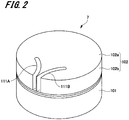
- Fig. 2 is a perspective view of the reagent vessel housing unit 7.
- Fig. 3 is a plan view of the reagent vessel housing unit.
- Fig. 4 is a sectional view of the reagent vessel housing unit 7.
- the reagent vessel housing unit 7 includes, for example, a housing 101 having the form of a substantially cylindrical vessel, a cover member 102 that covers an opening of the housing, a turntable 103 (see Fig. 4 ) disposed in the housing 101, and a table drive mechanism 104 (see Fig. 4 ).
- the turntable 103 is housed in an internal space 101a of the housing 101.
- the first reagent vessel 7a and the second reagent vessel 7b are placed on the turntable 103.
- the first reagent vessel 7a and the second reagent vessel 7b are disposed apart from each other with a predetermined interval therebetween along a peripheral direction of the turntable 103.
- the housing 101 keeps the first reagent vessel 7a and the second reagent vessel 7b, which are housed in the internal space 101a, cool at a predetermined temperature.
- the first reagent vessel 7a has a cap 71a that opens when pushed downward along an up-down direction.
- the second reagent vessel 7b has a cap 71b that opens when pushed downward in the up-down direction.
- the turntable 103 is supported so as to be rotatable in the peripheral direction by the table drive mechanism 104. In addition, the turntable 103 is rotated in a normal direction or in a reverse direction at a predetermined speed for each predetermined angular range in the peripheral direction thereof by the table drive mechanism 104.
- the cover member 102 has a hollow substantially cylindrical shape, with both ends in an axial direction being closed.
- the cover member 102 includes a substantially circular top surface portion 102a, a bottom surface portion 102c that opposes the top surface portion 102a and that covers the opening of the housing 101, and a side surface portion 102b that is substantially perpendicular to the top surface portion 102a and the bottom surface portion 102c.
- the cover member 102 has two grooved portions 111A and 111B through which a probe 201 that sucks a reagent passes.
- the two grooved portions 111A and 111B are continuously formed along the top surface portion 102a and the side surface portion 102b of the cover member 102, and are formed by cutting away the top surface portion 102a to form arcs.
- the two grooved portions 111A and 111B each have a first injection hole 112 and a second injection hole 113.
- First insertion holes 106 are formed in positions on the bottom surface portion 102c opposing the first injection holes 112.
- Second insertion holes 107 are formed in positions opposing the second injection holes 113.
- the first insertion holes 106 and the second insertion holes 107 extend through the bottom surface portion 102c in the up-down direction.
- the first injection holes 112 and the first insertion holes 106 are positioned above the first reagent vessel 7a housed in the housing 101.
- the second injection holes 113 and the second insertion hole 107 are positioned above the second reagent vessel 7b.
- the probe 201 passes through the first injection hole 112 and the first insertion hole 106.
- the probe 201 passes through the second injection hole 113 and the second insertion hole 107.
- a first cap opening/closing device 120A and a second cap opening/closing device 120B that open and close the cap 71a of the first reagent vessel 7a and the cap 71b of the second reagent vessel 7b are provided at the bottom surface portion 102c of the cover member 102.
- first cap opening/closing device 120A a structure of the first cap opening/closing device 120A and a structure of the second cap opening/closing device 120B are described in detail with reference to Figs. 5 to 8 . Since the first cap opening/closing device 120A and the second cap opening/closing device 120B have the same structure, the structure of the first cap opening/closing device 120A is only described here.
- Fig. 5 is a plan view of the first cap opening/closing device 120A and the second cap opening/closing device 120B.
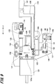
- Fig. 6 is a side view of the first cap opening/closing device 120A.
- Figs. 7 and 8 are each a sectional view of a main portion of the first cap opening/closing device 120A.
- the first cap opening/closing device 120A and the second cap opening/closing device 120B are provided on a support base 119 fixed to a surface of the bottom surface portion 102c.
- the first cap opening/closing device 120A includes a drive unit 121, a base member 122, a guide rail 123, a slider 124, a first opening/closing mechanism 135, a second opening/closing mechanism 136, a first shutter member 129, a second shutter member 130, and a sensor piece 131.
- the guide rail 123, a first sensor unit 132, and a second sensor unit 133 are fixed to the support base 119.
- the guide rail 123 is fixed to the support base 119 along a first direction X1 that is parallel to one surface of the bottom surface portion 102c.
- the slider 124 is supported so as to be slidable in the first direction X1 by the guide rail 123.
- the first sensor unit 132 is disposed closer to one side in the first direction X1 than the second sensor unit 133 is.
- an optical sensor including a light emitting section that emits light and a light receiving section that receives the light emitted from the light emitting section is used.
- a slide groove 116 is provided in the bottom surface portion 102c.
- the slide groove 116 is a recessed portion that is recessed by a predetermined depth from the one surface of the bottom surface portion 102c to the other surface of the bottom surface portion 102c.
- the slide groove 116 includes the first insertion hole 106 and the second insertion hole 107.
- the drive unit 121 is a direct-driven motor including a shaft member 121a.
- the drive unit 121 causes the shaft member 121a to advance and retreat in the first direction X1.
- the base member 122 is fixed to one end portion of the shaft member 121a in an axial direction via a fixing member 122a.
- the base member 122 is supported so as to be movable along the first direction X1 via the slider 124 by the guide rail 123.
- the base member 122 moves from an initial position shown in Fig. 5 to a first opening position (see Fig. 9 ) at the one side in the first direction X1, and to a second opening position (see Fig. 11 ) at the other side in the first direction X1.
- a first operating piece 127, a second operating piece 128, the first shutter member 129, the second shutter member 130, and the sensor piece 131 are fixed to the base member 122.
- the sensor piece 131 When the base member 122 is at the initial position, the sensor piece 131 is disposed between the first sensor unit 132 and the second sensor unit 133.
- the sensor piece 131 moves to a location between the light emitting section and the light receiving section of the first sensor unit 132, so that light from the light emitting unit is blocked.
- the base member 122 moves to the second opening position (see Fig. 11 )
- the sensor piece 131 moves to a location between the light emitting section and the light receiving section of the second sensor unit 133, so that light from the light emitting section is blocked. This makes it possible to determine whether the base member 122 has moved from the initial position to the first opening position (see Fig. 9 ) or to the second opening position (see Fig. 11 ).
- the present invention is not limited thereto.
- a mechanical sensor that performs mechanical switching between ON and OFF may be used.
- the first operating piece 127 and the second operating piece 128 are each formed by bending a flat member.
- the first operating piece 127 contacts or separates from a first rotary member 141 of the first opening/closing mechanism 135 (described later), and the second operating piece 128 contacts or separates from a second rotary member 171 of the second opening/closing mechanism 136 (described later).
- the first shutter member 129 and the second shutter member 130 are formed from substantially flat members.
- the first shutter member 129 and the second shutter member 130 are slidably placed in the slide groove 116 of the bottom surface portion 102c.
- the first shutter member 129 covers an opening of the first insertion hole 106 (see Fig. 7 )
- the second shutter member 130 covers an opening of the second insertion hole 107. This makes it possible to prevent cold air in the internal space 101a of the housing 101 (see Fig. 4 ) from flowing out to a side of the cover member 102 from the first insertion hole 106 and the second insertion hole 107, and to keep the temperature in the internal space 101a of the housing 101 at a predetermined temperature.
- the slide groove 116 in which the first shutter member 129 and the second shutter member 130 slide, it is possible to prevent the first shutter member 129 and the second shutter member 130 from interfering with the grooved portion 111A. In addition, it is possible to reduce the length from the top surface portion 102a of the cover member 102 to the bottom surface portion 102c, and to thinly form the cover member 102. It is to be noted that even if the slide groove 116 is not provided, the object of the present invention can be realized.
- the first opening/closing mechanism 135 is disposed at a side of the base member 122 where the first operating piece 127 is provided.
- the first opening/closing mechanism 135 includes the first rotary member 141, which is an exemplary first converting member, a supporting member 146 that rotatably supports the first rotary member 141, and a first pusher member 145.
- the first rotary member 141 has a substantially L shape, and includes a first piece portion 142 and a second piece portion 143 that is substantially perpendicularly bent from the first piece portion 142.
- a roller 142a is rotatably provided at an end portion of the first piece portion 142
- a roller 143a is rotatably provided at an end portion of the second piece portion 143.
- the first rotary member 141 is such that an intermediate portion between the first piece portion 142 and the second piece portion 143, that is, a location of the first rotary member 141 where it is bent is rotatably supported by the supporting member 146 via a rotary shaft 146a.
- the roller 142a at the first piece portion 142 contacts or separates from the first operating piece 127.
- the roller 143a at the second piece portion 143 abuts upon a head portion 151 of the first pusher member 145 (described later).
- the first piece portion 142 is positioned closer to the one side in the first direction X1 than the first operating piece 127 is.
- the first pusher member 145 includes, for example, the head portion 151, a shaft portion 152, a pushing portion 153, an adjusting plate 154, an adjusting screw 155, an adjusting spring 156, a spring bearing portion 157, and an urging spring 158.
- the shaft portion 152 extends through a through hole 119a of the support base 119 and a through hole 117 of the bottom surface portion 102c along a second direction Y, which is an up-down direction that is orthogonal to the first direction X1.
- One side of the shaft portion 152 in the second direction Y1 is exposed from the one surface of the bottom surface portion 102c to the interior of the cover member 102.
- the other side of the shaft portion 152 in the second direction Y1 is exposed from the other surface of the bottom surface portion 102c to a side of the internal space 101a of the housing 101.
- the head portion 151 is provided at the one side of the shaft portion 152 in the second direction Y1, that is, at a top portion thereof.
- a rectilinear slider 147 is fixed to the head portion 151.
- the rectilinear slider 147 is slidably supported by a rectilinear guide 148.
- the rectilinear guide 148 is disposed along the second direction Y1 from the one surface of the bottom surface portion 102c. Therefore, the rectilinear slider 147 slides along the rectilinear guide 148 in the second direction Y1. This restricts movements of the first pusher member 145 in directions other than the second direction Y1, and allows the first pusher member 145 to move in the second direction Y1.
- the spring bearing portion 157 through which the shaft portion 152 extends is fixed to the one surface of the bottom surface portion 102c.
- the urging spring 158 is interposed between the head portion 151 and the spring bearing portion 157.
- One end portion of the urging spring 158 in the second direction Y1 abuts upon the head portion 151, and the other end portion of the urging spring 158 in the second direction Y1 abuts upon the spring bearing portion 157.
- the urging spring 158 urges the head portion 151 towards one side in the second direction Y1.
- the first pusher member 145 is such that the head portion 151 abuts upon the second piece portion 143 of the first rotary member 141 to restrict movement to one side in the second direction Y1. Therefore, it is possible to, by an urging force of the urging spring 158, prevent the first pusher member 145 from being dislodged from the through holes 119a and 117 to the one side in the second direction Y1.
- the adjusting plate 154 is fixed to the other side of the shaft portion 152 in the second direction Y1, that is, a lower portion thereof, via a fixing screw 161.
- the flat pushing portion 153 is fixed to the adjusting plate 154 via the adjusting screw 155.
- the pushing portion 153 abuts upon the cap 71a of the first reagent vessel 7a.
- the pushing portion 153 pushes the cap 71a.
- the first reagent vessel 7a is such that a sealing member (not shown) in the cap 71a is pushed.
- the sealing member has a plurality of radially formed slits, and when pushed, the slits are uncovered.
- the pushing portion 153 has a through hole 153a and the adjusting plate 154 has a through hole 154a, the probe 201 passing through the through holes 153a and 154a.
- the adjusting spring 156 is interposed between the pushing portion 153 and the adjusting plate 154.
- One end portion of the adjusting spring 156 in the second direction Y1 abuts upon the adjusting plate 154, and the other end portion of the adjusting spring 156 in the second direction Y1 abuts upon the pushing portion 153.
- the interval between the pushing portion 153 and the adjusting plate 154 in the second direction Y1 and an urging force of the adjusting spring 156 are adjusted on the basis of a tightening amount of the adjusting screw 155. This makes it possible to adjust a pushing force of the first pusher member 145 with respect to the cap 71a of the first reagent vessel 7a.
- the second opening/closing mechanism 136 is disposed at a side of the base member 122 where the second operating piece 128 is provided.
- the second opening/closing mechanism 136 includes the second rotary member 171, which is an exemplary second converting member, a supporting member 176 that rotatably supports the second rotary member, and a second pusher member 175.
- the second rotary member 171 has a substantially L shape, and includes a first piece portion 172 and a second piece portion 173.
- a roller 172a is rotatably provided at an end portion of the first piece portion 172
- a roller 173a is rotatably provided at an end portion of the second piece portion 173.
- the second rotary member 171 is such that an intermediate portion between the first piece portion 172 and the second piece portion 173, that is, a location of the second rotary member 171 where it is bent, is rotatably supported by the supporting member 176 via a rotary shaft 176a.
- the roller 172a at the first piece portion 172 abuts upon the second operating piece 128.
- the roller 173a at the second piece portion 173 abuts upon a head portion 181 of the second pusher member 175 (described later).
- the first piece portion 172 is positioned closer to the other side in the first direction X1 than the second operating piece 128 is.
- the second pusher member 175 includes, for example, the head portion 181, a shaft portion 182, an adjusting nut 183, an adjusting plate 184, an adjusting screw 185, an adjusting spring 186, a spring bearing portion 187, and an urging spring 188.
- the shaft portion 182 extends through a through hole 119b of the support base 119 and a through hole 118 of the bottom surface portion 102c along the second direction Y.
- One side of the shaft portion 182 in the second direction Y1 is exposed from the one surface of the bottom surface portion 102c to the interior of the cover member 102.
- the other side of the shaft portion 182 in the second direction Y1 is exposed from the other surface of the bottom surface portion 102c to the side of the internal space 101a of the housing 101.
- the head portion 181 is provided at the one side of the shaft portion 182 in the second direction Y1, that is, at a top portion thereof.
- a rectilinear slider 177 is fixed to the head portion 181.
- the rectilinear slider 177 is slidably supported by a rectilinear guide 178.
- the rectilinear guide 178 is disposed along the second direction Y1 from the one surface of the bottom surface portion 102c. Therefore, the rectilinear slider 177 slides along the rectilinear guide 178 in the second direction Y1. This restricts movements of the second pusher member 175 in directions other than the second direction Y1, and allows the second pusher member 175 to move in the second direction Y1.
- the spring bearing portion 187 through which the shaft portion 182 extends is fixed to the one surface of the bottom surface portion 102c.
- the urging spring 188 is interposed between the head portion 181 and the spring bearing portion 187.
- the structure of the urging spring 188 is the same as the structure of the urging spring 158 of the first pusher member 145, and, thus, is not described.
- the adjusting plate 184 is fixed to the other side of the shaft portion 182 in the second direction Y1, that is, a lower portion thereof, via a fixing screw 162.
- the adjusting screw 185 which is an exemplary pushing portion, is fixed to the adjusting plate 184.
- the other end of the adjusting screw 185 in the second direction Y1 pushes the cap 71b of the second reagent vessel 7b (see Fig. 4 ).
- the adjusting nut 183 is provided at the other side of the adjusting screw 185 in the second direction Y1.
- the adjusting spring 186 is interposed between the adjusting nut 183 and the adjusting plate 184.
- the adjusting spring 186 is disposed at an outer side of the adjusting screw 185 in a peripheral direction thereof.
- One end portion of the adjusting spring 186 in the second direction Y1 abuts upon the adjusting plate 184, and the other end portion of the adjusting spring 186 in the second direction Y1 abuts upon the adjusting nut 183.
- An urging force of the adjusting spring 186 is adjusted by adjusting a tightening amount of the adjusting nut 183. This makes it possible to adjust a pushing force of the adjusting screw 185 with respect to the cap 71b by adjusting the urging force of the adjusting spring 186.
- Figs. 9 to 12 are each an explanatory view of an operation of the reagent vessel housing unit 7.
- the drive unit 121 is driven, and the shaft member 121a moves to the one side in the first direction X1.
- the base member 122 moves along the guide rail 123 from the initial position to the first opening position.
- the first sensor unit 132 detects that the base member 122 has moved from the initial position to the first opening position.
- the base member 122 moves, the first operating piece 127, the second operating piece 128, the first shutter member 129, and the second shutter member 130, which are fixed to the base member 122, move to the one side in the first direction X1. Therefore, as shown in Fig. 9 , the opening of the first insertion hole 106 that had been covered by the first shutter member 129 is uncovered. The opening of the second insertion hole 107 is covered by the second shutter member 130. This makes it possible to prevent cold air in the internal space 101a of the housing 101 from flowing out to the side of the cover member 102 from the second insertion hole 107 where suction is not performed.
- the first piece portion 142 of the first rotary member 141 of the first opening/closing mechanism 135 is pushed by the first operating piece 127 to the one side in the first direction X1.
- the first rotary member 141 is rotatably supported by the supporting member 146 via the rotary shaft 146a. Therefore, the first rotary member 141 rotates around the rotary shaft 146a as center. That is, the direction of a driving force of the drive unit 121 is converted from the first direction X1 to the second direction Y1 by the first rotary member 141.
- the second piece portion 143 moves to the other side in the second direction Y.
- the second piece portion 143 opposes the urging force of the urging spring 158 of the first pusher member 145, and pushes the head portion 151 to the other side in the second direction Y1.
- the head portion 151 and the shaft portion 152 move along the second direction Y1.
- the cap 71a of the first reagent vessel 7a (see Fig. 7 ) is pushed by the pushing portion 153 of the first pusher member 145, so that the first reagent vessel 7a is uncovered.
- the probe 201 moves to the other side in the second direction Y1, the probe 201 passes through the first injection hole 112 and the first insertion hole 106. That is, the probe 201 extends through the bottom surface portion 102c from the upper surface portion 102a of the cover member 102, and reaches the internal space 101a of the housing 101. Then, the first reagent housed in the first reagent vessel 7a is sucked by the probe 201.
- the suction of the first reagent by the probe 201 is completed, and the probe 201 retreats to a location above the first injection hole 112 (the one side in the second direction Y1), the drive unit 121 is driven, and the base member 122 moves to the initial position shown in Figs. 5 and 6 from the first opening position. Therefore, the first shutter member 129 moves to the other side in the first direction X1, and the opening of the first insertion hole 106 is covered again. Further, by moving the first operating piece 127 to the other side in the first direction X1, the pushing against the first rotary member 141 is stopped.
- the first pusher member 145 moves to the one side in the second direction Y1, and the head portion 151 pushes the second piece portion 143 of the first rotary member 141 to the one side in the second direction Y1.
- the first rotary member 141 rotates in a direction opposite to the direction shown in Fig. 10 , and returns to the initial position shown in Figs. 5 and 6 .
- the pushing against the cap 71a of the first reagent vessel 7a is stopped, and the first reagent vessel 7a is covered by the cap 71a.
- the drive unit 121 is driven, and the shaft member 121a moves to the other side in the first direction X1.
- the base member 122 secured to the shaft member 121a moves to the second opening position from the initial position.
- the base member 122 moves, the first operating piece 127, the second operating piece 128, the first shutter member 129, and the second shutter member 130, which are fixed to the base member 122, move to the other side in the first direction X1. Therefore, as shown in Fig. 11 , the opening of the second insertion opening 107 that had been covered by the second shutter member 130 is uncovered. The opening of the first insertion hole 106 is covered by the first shutter member 129. This makes it possible to prevent cold air in the internal space 101a of the housing 101 from flowing out to the side of the cover member 102 from the first insertion hole 106 where suction is not performed.
- the second operating piece 128 moves to the one side in the first direction X1, as shown in Fig. 12 , the first piece portion 172 of the second rotary member 171 of the second opening/closing mechanism 136 is pushed by the second operating piece 128 to the other side in the first direction X1.
- the second rotary member 171 is rotatably supported by the supporting member 176 via the rotary shaft 176a. Therefore, the second rotary member 171 rotates around the rotary shaft 176a as center. That is, the direction of a driving force of the drive unit 121 is converted from the first direction X1 to the second direction Y1 by the second rotary member 171.
- the head portion 181 of the second pusher member 175 is pushed to the other side in the second direction Y by the second piece portion 173 of the second rotary member 171.
- movements of the second pusher member 175 in directions other than the second direction Y1 are restricted by the rectilinear guide 178.
- the second pusher member 175 opposes an urging force of the urging spring 188, and moves to the other side in the second direction Y1.
- the cap 71b of the second reagent vessel 7b (see Fig. 4 ) is pushed by the adjusting screw 185 of the second pusher member 175, so that the second reagent vessel 7b is uncovered.
- the first operating piece 127 moves to the other side in the first direction X1
- the first operating piece 127 separates from the first piece portion 142 of the first rotary member 141 of the first opening/closing mechanism 135. Therefore, the first rotary member 141 of the first opening/closing mechanism 135 does not rotate.
- the first pusher member 145 remains at the initial position, and the cap 71a of the first reagent vessel 7a remains closed.
- the cap 71b of the second reagent vessel 7b can be closed by returning the base member 122 to the initial position from the second opening position.
- the reagent vessel housing unit 7 of the embodiment it is possible to open and close the caps 71a and 71b of the two respective reagent vessels 7a and 7b and uncover and cover the two insertion holes 106 and 107 by using one drive unit 121.
- This makes it possible to reduce the number of drive units 121, save electric power, and reduce the weight of the cover member 102.
- the present invention is not limited to the above-described embodiment illustrated in the drawings. Various modifications may be made within a scope that does not depart from the gist of the invention described in the claims. For example, although, in the above-described embodiment, an example in which the first shutter member 129 that covers the first insertion hole 106 and the second shutter member 130 that covers the second insertion hole 107 are formed as separate members is described, the first shutter member 129 and the second shutter member 130 may be integrated with each other.
- the present invention is not limited thereto.
- the cap of the first reagent vessel 7a and the cap of the second reagent vessel 7b may be opened and closed by sliding the caps in the first direction X1.
- the first opening/closing mechanism and the second opening/closing mechanism are operated by the base member and are slid along the first direction X1 to slide the cap of the first reagent vessel and the cap of the second reagent vessel.
- an immunology device that performs immunology tests is used
- the present invention is not limited thereto.
- a biochemical analysis device that is used in analyzing biological samples, such as blood or urine, or devices that perform various other types of analyses, such as a water analysis or a food analysis, may be used.
Landscapes
- Physics & Mathematics (AREA)
- Health & Medical Sciences (AREA)
- Life Sciences & Earth Sciences (AREA)
- Chemical & Material Sciences (AREA)
- Analytical Chemistry (AREA)
- Biochemistry (AREA)
- General Health & Medical Sciences (AREA)
- General Physics & Mathematics (AREA)
- Immunology (AREA)
- Pathology (AREA)
- Automatic Analysis And Handling Materials Therefor (AREA)
Applications Claiming Priority (2)
| Application Number | Priority Date | Filing Date | Title |
|---|---|---|---|
| JP2014058292A JP6326256B2 (ja) | 2014-03-20 | 2014-03-20 | 試薬容器収容ユニット及び自動分析装置 |
| PCT/JP2015/057578 WO2015141599A1 (fr) | 2014-03-20 | 2015-03-13 | Unité de logement de récipients à réactifs et dispositif d'analyse automatique |
Publications (2)
| Publication Number | Publication Date |
|---|---|
| EP3121602A1 true EP3121602A1 (fr) | 2017-01-25 |
| EP3121602A4 EP3121602A4 (fr) | 2017-11-22 |
Family
ID=54144568
Family Applications (1)
| Application Number | Title | Priority Date | Filing Date |
|---|---|---|---|
| EP15765498.9A Withdrawn EP3121602A4 (fr) | 2014-03-20 | 2015-03-13 | Unité de logement de récipients à réactifs et dispositif d'analyse automatique |
Country Status (4)
| Country | Link |
|---|---|
| US (1) | US9952243B2 (fr) |
| EP (1) | EP3121602A4 (fr) |
| JP (1) | JP6326256B2 (fr) |
| WO (1) | WO2015141599A1 (fr) |
Families Citing this family (2)
| Publication number | Priority date | Publication date | Assignee | Title |
|---|---|---|---|---|
| WO2016203856A1 (fr) * | 2015-06-17 | 2016-12-22 | 株式会社 日立ハイテクノロジーズ | Analyseur automatique |
| JP7165466B2 (ja) * | 2018-09-21 | 2022-11-04 | 株式会社日立ハイテク | 自動分析装置 |
Family Cites Families (11)
| Publication number | Priority date | Publication date | Assignee | Title |
|---|---|---|---|---|
| JPS58134773U (ja) | 1982-03-06 | 1983-09-10 | オリンパス光学工業株式会社 | 分析装置に用いる試薬容器 |
| JPH0720132A (ja) | 1993-06-30 | 1995-01-24 | Kyowa Medex Co Ltd | 試薬供給装置の試薬ボトル蓋構造 |
| EP0736182A1 (fr) | 1994-09-21 | 1996-10-09 | Roche Diagnostics GmbH | Dispositif d'ouverture de contenants a couvercle a charniere |
| JP2004156971A (ja) * | 2002-11-05 | 2004-06-03 | Olympus Corp | 試薬容器および自動分析装置 |
| JP4160364B2 (ja) | 2002-11-06 | 2008-10-01 | オリンパス株式会社 | 試薬容器および自動分析装置 |
| JP4961120B2 (ja) | 2005-08-04 | 2012-06-27 | ベックマン コールター, インコーポレイテッド | 試薬保冷装置 |
| JP4223029B2 (ja) * | 2005-08-10 | 2009-02-12 | オリンパス株式会社 | 試薬容器 |
| JP4861787B2 (ja) | 2006-10-10 | 2012-01-25 | シスメックス株式会社 | 試薬収容具および試薬容器保持具 |
| JP5042197B2 (ja) * | 2008-10-31 | 2012-10-03 | 株式会社日立ハイテクノロジーズ | 化学分析装置 |
| JP3159758U (ja) * | 2010-03-12 | 2010-06-03 | 株式会社日立ハイテクノロジーズ | 自動分析装置 |
| JP2014032099A (ja) | 2012-08-03 | 2014-02-20 | Hitachi High-Technologies Corp | 容器蓋開閉機構及びこれを備える自動分析装置 |
-
2014
- 2014-03-20 JP JP2014058292A patent/JP6326256B2/ja active Active
-
2015
- 2015-03-13 US US15/126,613 patent/US9952243B2/en not_active Expired - Fee Related
- 2015-03-13 EP EP15765498.9A patent/EP3121602A4/fr not_active Withdrawn
- 2015-03-13 WO PCT/JP2015/057578 patent/WO2015141599A1/fr active Application Filing
Also Published As
| Publication number | Publication date |
|---|---|
| US20170082647A1 (en) | 2017-03-23 |
| EP3121602A4 (fr) | 2017-11-22 |
| US9952243B2 (en) | 2018-04-24 |
| JP2015184034A (ja) | 2015-10-22 |
| WO2015141599A1 (fr) | 2015-09-24 |
| JP6326256B2 (ja) | 2018-05-16 |
Similar Documents
| Publication | Publication Date | Title |
|---|---|---|
| JP7233403B2 (ja) | 前処理カルーセルを有する診断分析装置および関連方法 | |
| US10775398B2 (en) | Automated diagnostic analyzers having vertically arranged carousels and related methods | |
| EP0712000B1 (fr) | Disposif d'incubation | |
| US7790114B2 (en) | Reagent-containing assembly | |
| CA2650258C (fr) | Systeme analytique automatise constant et a acces aleatoire | |
| US5635364A (en) | Assay verification control for an automated analytical system | |
| US8007722B2 (en) | Analyzer | |
| US9116129B2 (en) | Chemical analyzer | |
| EP1465728B1 (fr) | Ensemble de recipients empilables d'aliquotes | |
| JP5032088B2 (ja) | 分析装置および試薬収容具 | |
| AU2009314184B2 (en) | Reagent container pack | |
| JP2005509172A (ja) | 双方向性磁気試料ラック搬送システム | |
| US20170307534A1 (en) | Luminescence Measuring Device and Automatic Analysis Device | |
| US8066943B2 (en) | Clinical analyzer having a variable cycle time and throughput | |
| US20080063567A1 (en) | Analyzer with automatically actuated movable closure of pipetting openings | |
| US9889443B2 (en) | Sample analyzer and sample analyzing method | |
| JP6336791B2 (ja) | 自動分析装置における試薬容器受容位置のための閉鎖システム | |
| CA2462484A1 (fr) | Analyseur a sonde multifonctions fixe | |
| US7569189B2 (en) | Opening and closing a container | |
| CN210090483U (zh) | 一种样本分析仪及其测光设备 | |
| US9952243B2 (en) | Reagent vessel housing unit and automatic analysis device | |
| CN110809496B (zh) | 用于多通道免疫测定系统的模块化洗涤桥 | |
| CN220525834U (zh) | 样本分析仪 | |
| AU2013257454B2 (en) | Reagent container pack |
Legal Events
| Date | Code | Title | Description |
|---|---|---|---|
| PUAI | Public reference made under article 153(3) epc to a published international application that has entered the european phase |
Free format text: ORIGINAL CODE: 0009012 |
|
| 17P | Request for examination filed |
Effective date: 20160915 |
|
| AK | Designated contracting states |
Kind code of ref document: A1 Designated state(s): AL AT BE BG CH CY CZ DE DK EE ES FI FR GB GR HR HU IE IS IT LI LT LU LV MC MK MT NL NO PL PT RO RS SE SI SK SM TR |
|
| AX | Request for extension of the european patent |
Extension state: BA ME |
|
| DAV | Request for validation of the european patent (deleted) | ||
| DAX | Request for extension of the european patent (deleted) | ||
| RIC1 | Information provided on ipc code assigned before grant |
Ipc: G01N 35/02 20060101AFI20171012BHEP Ipc: G01N 35/00 20060101ALI20171012BHEP |
|
| A4 | Supplementary search report drawn up and despatched |
Effective date: 20171019 |
|
| GRAP | Despatch of communication of intention to grant a patent |
Free format text: ORIGINAL CODE: EPIDOSNIGR1 |
|
| INTG | Intention to grant announced |
Effective date: 20181120 |
|
| STAA | Information on the status of an ep patent application or granted ep patent |
Free format text: STATUS: THE APPLICATION IS DEEMED TO BE WITHDRAWN |
|
| 18D | Application deemed to be withdrawn |
Effective date: 20190402 |