EP3120798B1 - Elektromagnetisches system zum nachverfolgen einer position - Google Patents
Elektromagnetisches system zum nachverfolgen einer position Download PDFInfo
- Publication number
- EP3120798B1 EP3120798B1 EP16179117.3A EP16179117A EP3120798B1 EP 3120798 B1 EP3120798 B1 EP 3120798B1 EP 16179117 A EP16179117 A EP 16179117A EP 3120798 B1 EP3120798 B1 EP 3120798B1
- Authority
- EP
- European Patent Office
- Prior art keywords
- coil
- coils
- bri
- receiver coil
- frequency
- Prior art date
- Legal status (The legal status is an assumption and is not a legal conclusion. Google has not performed a legal analysis and makes no representation as to the accuracy of the status listed.)
- Active
Links
Images
Classifications
-
- G—PHYSICS
- G01—MEASURING; TESTING
- G01D—MEASURING NOT SPECIALLY ADAPTED FOR A SPECIFIC VARIABLE; ARRANGEMENTS FOR MEASURING TWO OR MORE VARIABLES NOT COVERED IN A SINGLE OTHER SUBCLASS; TARIFF METERING APPARATUS; MEASURING OR TESTING NOT OTHERWISE PROVIDED FOR
- G01D5/00—Mechanical means for transferring the output of a sensing member; Means for converting the output of a sensing member to another variable where the form or nature of the sensing member does not constrain the means for converting; Transducers not specially adapted for a specific variable
- G01D5/12—Mechanical means for transferring the output of a sensing member; Means for converting the output of a sensing member to another variable where the form or nature of the sensing member does not constrain the means for converting; Transducers not specially adapted for a specific variable using electric or magnetic means
- G01D5/14—Mechanical means for transferring the output of a sensing member; Means for converting the output of a sensing member to another variable where the form or nature of the sensing member does not constrain the means for converting; Transducers not specially adapted for a specific variable using electric or magnetic means influencing the magnitude of a current or voltage
- G01D5/20—Mechanical means for transferring the output of a sensing member; Means for converting the output of a sensing member to another variable where the form or nature of the sensing member does not constrain the means for converting; Transducers not specially adapted for a specific variable using electric or magnetic means influencing the magnitude of a current or voltage by varying inductance, e.g. by a movable armature
- G01D5/2006—Mechanical means for transferring the output of a sensing member; Means for converting the output of a sensing member to another variable where the form or nature of the sensing member does not constrain the means for converting; Transducers not specially adapted for a specific variable using electric or magnetic means influencing the magnitude of a current or voltage by varying inductance, e.g. by a movable armature by influencing the self-induction of one or more coils
-
- A—HUMAN NECESSITIES
- A61—MEDICAL OR VETERINARY SCIENCE; HYGIENE
- A61B—DIAGNOSIS; SURGERY; IDENTIFICATION
- A61B34/00—Computer-aided surgery; Manipulators or robots specially adapted for use in surgery
- A61B34/20—Surgical navigation systems; Devices for tracking or guiding surgical instruments, e.g. for frameless stereotaxis
-
- A—HUMAN NECESSITIES
- A61—MEDICAL OR VETERINARY SCIENCE; HYGIENE
- A61B—DIAGNOSIS; SURGERY; IDENTIFICATION
- A61B90/00—Instruments, implements or accessories specially adapted for surgery or diagnosis and not covered by any of the groups A61B1/00 - A61B50/00, e.g. for luxation treatment or for protecting wound edges
- A61B90/39—Markers, e.g. radio-opaque or breast lesions markers
-
- G—PHYSICS
- G01—MEASURING; TESTING
- G01D—MEASURING NOT SPECIALLY ADAPTED FOR A SPECIFIC VARIABLE; ARRANGEMENTS FOR MEASURING TWO OR MORE VARIABLES NOT COVERED IN A SINGLE OTHER SUBCLASS; TARIFF METERING APPARATUS; MEASURING OR TESTING NOT OTHERWISE PROVIDED FOR
- G01D5/00—Mechanical means for transferring the output of a sensing member; Means for converting the output of a sensing member to another variable where the form or nature of the sensing member does not constrain the means for converting; Transducers not specially adapted for a specific variable
- G01D5/12—Mechanical means for transferring the output of a sensing member; Means for converting the output of a sensing member to another variable where the form or nature of the sensing member does not constrain the means for converting; Transducers not specially adapted for a specific variable using electric or magnetic means
- G01D5/14—Mechanical means for transferring the output of a sensing member; Means for converting the output of a sensing member to another variable where the form or nature of the sensing member does not constrain the means for converting; Transducers not specially adapted for a specific variable using electric or magnetic means influencing the magnitude of a current or voltage
- G01D5/20—Mechanical means for transferring the output of a sensing member; Means for converting the output of a sensing member to another variable where the form or nature of the sensing member does not constrain the means for converting; Transducers not specially adapted for a specific variable using electric or magnetic means influencing the magnitude of a current or voltage by varying inductance, e.g. by a movable armature
- G01D5/204—Mechanical means for transferring the output of a sensing member; Means for converting the output of a sensing member to another variable where the form or nature of the sensing member does not constrain the means for converting; Transducers not specially adapted for a specific variable using electric or magnetic means influencing the magnitude of a current or voltage by varying inductance, e.g. by a movable armature by influencing the mutual induction between two or more coils
-
- A—HUMAN NECESSITIES
- A61—MEDICAL OR VETERINARY SCIENCE; HYGIENE
- A61B—DIAGNOSIS; SURGERY; IDENTIFICATION
- A61B34/00—Computer-aided surgery; Manipulators or robots specially adapted for use in surgery
- A61B34/20—Surgical navigation systems; Devices for tracking or guiding surgical instruments, e.g. for frameless stereotaxis
- A61B2034/2046—Tracking techniques
- A61B2034/2051—Electromagnetic tracking systems
-
- A—HUMAN NECESSITIES
- A61—MEDICAL OR VETERINARY SCIENCE; HYGIENE
- A61B—DIAGNOSIS; SURGERY; IDENTIFICATION
- A61B34/00—Computer-aided surgery; Manipulators or robots specially adapted for use in surgery
- A61B34/20—Surgical navigation systems; Devices for tracking or guiding surgical instruments, e.g. for frameless stereotaxis
- A61B2034/2072—Reference field transducer attached to an instrument or patient
-
- A—HUMAN NECESSITIES
- A61—MEDICAL OR VETERINARY SCIENCE; HYGIENE
- A61B—DIAGNOSIS; SURGERY; IDENTIFICATION
- A61B90/00—Instruments, implements or accessories specially adapted for surgery or diagnosis and not covered by any of the groups A61B1/00 - A61B50/00, e.g. for luxation treatment or for protecting wound edges
- A61B90/39—Markers, e.g. radio-opaque or breast lesions markers
- A61B2090/397—Markers, e.g. radio-opaque or breast lesions markers electromagnetic other than visible, e.g. microwave
-
- A—HUMAN NECESSITIES
- A61—MEDICAL OR VETERINARY SCIENCE; HYGIENE
- A61B—DIAGNOSIS; SURGERY; IDENTIFICATION
- A61B90/00—Instruments, implements or accessories specially adapted for surgery or diagnosis and not covered by any of the groups A61B1/00 - A61B50/00, e.g. for luxation treatment or for protecting wound edges
- A61B90/39—Markers, e.g. radio-opaque or breast lesions markers
- A61B2090/3983—Reference marker arrangements for use with image guided surgery
Definitions
- the present application relates to the field of electromagnetic position monitoring systems or electromagnetic locating systems. More particularly, it relates to electromagnetic position monitoring systems adapted to the medical field, for example for locating one or more tools used by a surgeon during a medical procedure.
- the joint analysis of the fields emitted by the emission coils and the fields received by the reception coils makes it possible to determine the position and / or the orientation of the reception device with respect to the transmission device.
- an embodiment provides an electromagnetic position monitoring system, comprising: a device for emitting an electromagnetic field comprising at least one transmission coil and, connected to the transmission coil, a first generator of an electrical signal for excitation of the transmission coil; a device for receiving the electromagnetic field emitted by the transmitting device, comprising at least one receiving coil and, connected to the receiving coil, a circuit for reading an electrical signal induced in the receiving coil; and a system for measuring at least one parameter of the receiving device, comprising, directly connected to the receiving coil by a track or a conducting wire, a second generator of an electrical signal for excitation of the receiving coil.
- the parameter is a parameter of the group comprising the series resistance and the own inductance of the receiving coil.
- the receiving device comprises at least two receiving coils
- the parameter is a parameter of the group comprising the series resistance of each receiving coil, the own inductance of each receiving coil, and the coefficient of reception. mutual inductance between two receiving coils.
- the parameter comprises the series resistance of each receiving coil
- the measurement system is adapted, for measuring the series resistance, to apply to a receiving coil end a DC voltage or a sinusoidal voltage of frequency at least 20 times lower than the cutoff frequency of the coil.
- the parameter comprises the own inductance of each receiver coil
- the system The measuring device is adapted, for measuring the own inductance, to apply a sinusoidal voltage with a frequency greater than the cut-off frequency of the coil to an end of the receiving coil.
- the parameter comprises the coefficient of mutual inductance between two reception coils
- the measurement system is adapted, for measuring the coefficient, to be applied on one end of one of the two reception coils a voltage sinusoidal frequency greater than the cutoff frequency of the coil.
- the read circuit comprises, associated with each receiving coil, a read amplification stage comprising an operational amplifier whose inverting input is connected to the output via a resistor of against -action and whose non-inverting input is connected to an application node of a reference potential, a first end of the receiving coil being connected to the inverting input of the operational amplifier.
- the second generator comprises, associated with each receiving coil, a controllable voltage source connected between the second end of the receiving coil and the application node of a reference potential.
- the second generator comprises a digital frequency synthesizer.
- the transmission coil comprises three transmission coils oriented along distinct axes
- the receiving coil comprises three reception coils oriented along distinct axes.
- connection will be used to designate a direct electrical connection, without intermediate electronic component, for example by means of one or more conducting tracks or conducting wires, and the term “coupled” or term “connected” to designate either a direct electrical connection (meaning “connected”) or a connection via one or more intermediate components (resistor, capacitor, etc.).
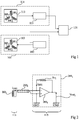
- the figure 1 schematically shows, in block form, an example of an electromagnetic position tracking system.
- the system of figure 1 comprises a device 101 for emitting an electromagnetic field comprising a set 103 of one or more emission coils.
- the assembly 103 comprises three transmitting coils BE 1 , BE 2 and BE 3 oriented along three distinct axes, for example along the three axes of FIG. an orthogonal reference.
- the transmitting device 101 further comprises a device 105 for generating electrical signals (voltages or currents) alternating excitation of the coils of the assembly 103, for example sinusoidal signals.
- the generator 105 is connected to at least one terminal of each of the coils BE 1 , BE 2 and BE 3 .
- the system of figure 1 further comprises a device 111 for receiving the electromagnetic field emitted by the transmitting device 101.
- the receiving device 111 comprises an assembly 113 of one or more receiving coils.
- the assembly 113 comprises three receiving coils BR 1 , BR 2 and BR 3 oriented along three distinct axes, for example along the three axes of a orthogonal reference.
- the receiving device 111 further comprises a device 115 for reading the electrical signals (voltages or currents) induced in the coils of the assembly 113 under the effect of the alternating fields emitted by the emission coils.
- the system of figure 1 further comprises a processing device 121, comprising for example a microprocessor, connected on the one hand to the generator 105 of the transmission device 101 and on the other hand to the reading device 115 of the receiving device 111.
- the links between the generator 105 and the processing device 121 and between the reading device 115 and the processing device 121 may be wired links or wireless links.
- the generator 105 is adapted to transmitting to the processing device 121 signals representative of the excitation signals that it applies across the transmit coils BE 1 , BE 2 and BE 3 .
- the reading device 115 is adapted to transmit to the processing device 121 signals representative of the signals read across the receiving coils BR 1 , BR 2 and BR 3 .
- the signals transmitted by the devices 105 and 115 to the processing device 121 are, for example, digital signals.
- the generator 105 comprises a circuit (not shown) for sampling and digitizing the analog excitation signals applied across the transmit coils BE 1 , BE 2 and BE 3
- the reading device 115 comprises a circuit (not shown) for sampling and digitizing the analog signals read across the receiving coils BR 1 , BR 2 and BR 3 .
- the set 103 of emission coils of the transmission device 101 defines a reference frame for locating the set 113 of reception coils of the reception device 111.
- the set 113 of reception coils can be fixed on an object to locate.
- the assembly 103 of emission coils can be fixed on the body of a patient or on a structure external to the body of the patient. serving as a repository.
- the assembly 113 of receiving coils can be fixed on a surgical tool that it is desired to be able to locate during the procedure.
- the emission coils BE 1 , BE 2 and BE 3 of the transmission device 101 each emit an alternating electromagnetic field.
- the generator 105 is configured to simultaneously apply different frequency excitation signals to the different coils of the assembly 103, in which case the coils of the assembly 103 simultaneously emit electromagnetic fields. alternative distinct frequencies. This makes it possible, at the level of the receiving device, to be able to spectrally discriminate the fields coming from the different emission coils.
- the generator is configured to sequentially apply to the different coils of the set 103 excitation signals of the same frequency, so that at a given instant, only one of the coils of the set 103 emits an electromagnetic field.
- the transmission frequency or frequencies of the device 101 are for example in the range from 1 to 50 kHz.
- Signals (for example digital) representative of the excitation signals applied by the generator 105 to the coils BE 1 , BE 2 and BE 3 are transmitted to the processing unit 121.
- reception device 111 At the level of the reception device 111, electrical signals are induced in the reception coils BR 1 , BR 2 and BR 3 under the effect of the electromagnetic fields emitted by the emission coils BE 1 , BE 2 and BE 3 . These signals are measured by the reading device 115 and transmitted (for example in digital form) to the processing unit 121.
- the processing device 121 comprises a synchronous and filtering demodulation unit (not shown in the figure) adapted from the signals transmitted by the generator 105 and the reading device 115, to be determined, for each of the reception coils of the 113, the intensity of the field picked up by the coil coming from each of the emission coils of the assembly 103. From the intensity of the fields picked up by the reception coils, the processing device 121 determines the position and / or orientation of the set of receive coils 113 relative to the set of transmit coils 103.
- the synchronous demodulation and filtering unit determines nine field values respectively corresponding to the field received by the coil BR 1 coming from the coil BE 1 , to the field received by the coil BR 1 from the BE 2 coil, to the field received by the coil BR 1 from the BE 3 coil, to the field received by the coil BR 2 from the BE coil 1 , to the field received by the coil BR 2 from the BE 2 coil, to the field received by the coil BR 2 from the coil BE 3 , to the field received by the coil BR 3 coming from the coil BE 1 , to the field received by the coil BR 3 coming from the coil BE 2 , and the field received by the coil BR 3 from the coil BE 3 .
- the processing unit 121 calculates the spatial position coordinates of the set of receive coils 113 along the three axes of the mark defined by the transmit coils, and three angular values defining the Orientation of the set of reception coils 113 with respect to the axes of the mark defined by the transmitting coils (this is referred to as a location system with six degrees of freedom).
- the accuracy of a locating system of the type described in relation to the figure 1 depends in particular on the accuracy of the measurement of the fields picked up by the coils of the receiving device. Thus, to obtain a good location accuracy, it is necessary to know precisely the transfer function of conversion into field values of the electrical signals (voltages or currents) measured across the coils of the receiving device 111.
- the reading device 115 of the receiving device 111 comprises a transimpedance type amplification device.
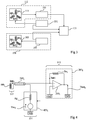
- An example of such an amplification device is illustrated in figure 2 .
- the figure 2 shows in greater detail a part of the reception device 111 of an electromagnetic position-tracking system of the type described in connection with the figure 1 .
- the reading device 115 comprises, associated with each of the reception coils BR i , with i integer ranging from 1 to 3, an amplification device 201 i of transimpedance type, that is to say comprising an operational amplifier 203 i whose inverting input (-) is connected to the output by a feedback resistor Rc i and whose non-inverting input (+) is connected to an application node of a reference potential GND, for example ground.
- an amplification device 201 i of transimpedance type that is to say comprising an operational amplifier 203 i whose inverting input (-) is connected to the output by a feedback resistor Rc i and whose non-inverting input (+) is connected to an application node of a reference potential GND, for example ground.
- the coil BR i has its two ends connected, for example by means of a coaxial cable 205 i respectively to the inverting input (-) and the non-inverting input (+) of the operational amplifier 203 i .
- the coil BR i is short-circuited because of the virtual ground present on the inverting input (-) of the operational amplifier 203 i .
- the coil BR i is crossed by a current i BRi proportional to the intensity of the magnetic field received by the coil.
- the operational amplifier 203 i supplies on its output node a voltage Vout i (referenced with respect to the node GND) amplified image of the current i BRi .
- the reading device 115 may further comprise, associated with each of the reception coils BR i , a sampling and digitizing circuit (not shown) adapted to sample and digitize the voltage Vout i , the digital output of this circuit being connected. to the processing device 121.
- the frequency response of the conversion gain K BRi is a high-pass response with a gain equal to (M BRi / L BRi ) * Rc i and a cut-off frequency equal to Rs BRi / (2 ⁇ L BRi ).
- the value of the inductance L BRi although less dependent on temperature variations, remains nevertheless liable to undergo drifts (depending in particular on the materials used, such as for example the use or not of a ferromagnetic core).
- the precise knowledge of this value can also be useful in a calibration phase of the electromagnetic system to constrain certain coefficients used by the calculation algorithm for determining the position and / or orientation.
- each coil re-emits a parasitic magnetic field proportional to the induced current flowing through it, this parasitic field being itself picked up by the other reception coils.
- the field B picked up by the reception coil BR 3 will not only comprise the useful field which one wishes to measure, namely the field emitted by the coils BE 1 , BE 2 and BE 3 of the transmission device 101, but also a parasitic field re-transmitted by the receiving coil BR 1 , and a parasitic field re-transmitted by the receiving coil BR 2 .
- the useful field picked up by each of the coils BR i it is necessary to know the parasitic fields emitted by the other reception coils of the assembly 113. For this, it is necessary to know with precision the coefficients of mutual inductance between the coils. different reception coils.
- the values of the mutual inductance coefficients are not very dependent on temperature variations, and fluctuate little in the short term. However, as for the inductance values L BRi , the knowledge of the mutual inductance coefficients can be useful in the calibration phase of the electromagnetic system to constrain certain coefficients used by the calculation algorithm for determining the position and / or orientation.
- the figure 3 schematically shows, in block form, an example of an embodiment of an electromagnetic position tracking system.
- the system of figure 3 includes elements common to the system of figure 1 . These items will not be detailed again. In the description that follows, only the differences between the system of the figure 3 and the system of figure 1 will be detailed.
- the system of figure 3 differs from the system of figure 1 in that it comprises, in addition to the transmission device 101, the receiving device 111 and the processing unit 121, a measurement system of the parameters of the receiving device 111, this measurement system making it possible to determine in-situ, that is to say during a phase of use of the system locating device for tracking the position of an object, the values of the parameters Rs BRi and / or L BRi and / or Ml i, i ' of the arrangement formed by the reception coils BR i and the reading amplification stages 201 i associated with the receiving coils.
- the parameter measuring system comprises a controllable device 331 for generating electrical signals (voltages or currents) for excitation of the reception coils of the assembly 113.
- the generator 331 is connected to at least one terminal of each of the reception coils. BR 1 , BR 2 and BR 3 .
- the generator 331 is connected to the processing device 121 by a wired or wireless link.
- the generator 331 is adapted to transmit to the processing device 121 signals (for example digital) representative of the excitation signals that it applies across the receiving coils BR 1 , BR 2 and BR 3 .
- the figure 4 further represents part of the location system of the figure 3 .
- the reading device 115 comprises, as in the example of the figure 2 associated with each of the reception coils BR i , a transimpedance-type amplification device 201 i comprising an operational amplifier 203 i whose inverting input (-) is connected to the output by a feedback resistor Rc i and whose non-inverting input (+) is connected to an application node of a reference potential GND, for example ground.
- the generator 331 comprises, associated with each of the reception coils BR i , a controllable voltage source 433 i connected to one end of the coil BR i and adapted to apply a voltage Vm i , referenced with respect to the node GND, on this end of the coil BR i .
- the other end of the coil BR i is connected to the inverting input (-) of the operational amplifier 203 i .
- a cable 205 i connects the two ends of the coil BR i respectively to the inverting input (-) of the operational amplifier 203 i and to the output of the source of controllable voltage 433 i .
- the coil BR i is not connected directly to the non-inverting input (+) of the operational amplifier 203 i , but is connected to the non-inverting input (+) via the source controllable voltage 433 i and the reference node GND.
- the series resistor Rs BRi associated with the receiving coil BR i that is to say the series resistance of the circuit connected between the inverting input (-) and the noninverting input (+) of the operational amplifier 203 i , not only comprises the resistance of the coil BR i and the resistance of the cable 205 i , but also comprises the series resistance R g of the controllable voltage source 433 i .
- the generator 331 controls the application, via the controllable voltage source 433 i , of a continuous or sinusoidal voltage Vm i on the terminal of the coil BR i connected to the voltage source 433 i .
- Vm i V ref cos 2 ⁇ f i t
- V ref denotes the amplitude of the sinusoidal voltage and f i its frequency.
- the voltage Vm i is amplified by the transimpedance amplification stage 201 i , the amplified image of this voltage forming a component of the output voltage V orti of the amplification stage 201 i .
- the frequency f i of the voltage Vm i is preferably chosen much lower than the cutoff frequency of the coil (equal to RS BRi / 2 ⁇ L BRi ), so that the impedance of the inductance of the coil BR i can be neglected before the series resistance to be measured.
- the frequency f i is chosen at least 20 times smaller than the cutoff frequency of the coil.
- the frequency f i can be in the range from 1 to 20 Hz for a cutoff frequency of the coil substantially equal to 1 kHz.
- the amplitude V ref of the sinusoidal voltage is chosen so as not to saturate the operational amplifier 203 i , that is to say so that the output voltage V orti of the amplification stage remains lower than the saturation output voltage of the amplifier 203i.
- the generator 331 controls the application, via the controllable voltage source 433 i , of a sinusoidal alternating voltage Vm i on the terminal of the coil BR i connected to the voltage source 433 i .
- V m i V ref cos 2 ⁇ f i t
- the frequency f i of the voltage Vm i is chosen close to or greater than the cutoff frequency of the coil (equal to RS BRi / 2 ⁇ L BRi ), so that the impedance of the inductance of the coil BR i is not negligible in front of the series resistance of the coil Rs BRi .
- the frequency f i is chosen between 1 and 50 times the cutoff frequency of the coil.
- the frequency f i can be in the range from 1 to 20 kHz for a cut-off frequency of the order of 1 kHz.
- the frequency f i is different from the transmission frequency or frequencies of the transmission device 101.
- the frequency f i is smaller than the lowest transmission frequency of the device transmission 101, or greater than the largest transmission frequency of the transmission device 101.
- the amplitude V ref of the voltage Vm i is chosen so as not to saturate the operational amplifier 203 i .
- the voltage Vm i is amplified by the transimpedance amplification stage 201 i .
- the amplified image of the voltage Vm i thus forms a frequency component f i of the output voltage V orti of the amplification stage 201 i , expressed as follows:
- V outifi t V ref cos 2 ⁇ f i t rc i R s BiS + The BiS j ⁇
- the processing device 121 can determine the value of the inductance L BRi by the following formula:
- the BiS 1 ⁇ R vs i 2 V ref V outifi 2 - R s Bri 2
- the generator 331 controls the application, via the controllable voltage source 433 i , of an alternating voltage Vm i sinusoidal on the terminal of the coil BR i connected to the voltage source 433 i .
- the frequency f i of the voltage Vm i is chosen close to or greater than the cutoff frequency of the RS BRi / 2 ⁇ L BRi coil , so that the impedance of the inductance of the coil BR i is not negligible in front of the series resistor Rs BRi .
- the frequency f i is chosen between 1 and 50 times the cutoff frequency of the coil.
- the frequency f i lies in the range from 1 to 20 kHz for a coil breaking frequency of about 1 kHz.
- the frequency f i is preferably different from the transmission frequency or frequencies of the transmission device 101.
- the frequency f i is smaller than the smallest frequency transmission of the transmission device 101, or greater than the largest transmission frequency of the transmission device 101.
- the amplitude V ref of the voltage Vm i is chosen so as not to saturate the operational amplifier 203 i .
- the applied voltage via the controllable voltage source 433 i ' , on the terminal of the coil BR i' connected to the voltage source 433 i ' , is for example zero. In any case, this voltage has no frequency component f i .
- the coil BR i emits an alternating electromagnetic field of frequency f i .
- V outi' a voltage V outi'
- V outi ' t - j ⁇ ml i , i ' i BiS cos 2 ⁇ f i t R vs i ' R s BiS ' + The BiS ' j ⁇
- the different coefficients of mutual inductance of the set 113 of reception coils namely the coefficients Ml 1.2 , Ml 1.3 and Ml 1.3 in the example with three reception coils can be determined simultaneously using separate excitation frequencies f i .
- the different coefficients of mutual inductance can be determined sequentially by using the same excitation frequency f i .
- Measurements of the parameters Rs BRi , L BRi and / or Ml i, i ' can be performed during a calibration phase prior to a position monitoring phase, and / or during the actual position tracking phase.
- the measurements of the parameters Rs BRi , L BRi and / or Ml i, i ' can be carried out continuously in parallel with the measurements of the electromagnetic fields coming from the emission device, provided that the excitation frequency or frequencies applied by the parameter measuring system on the receiving coils are different from the transmission frequency or frequencies of the transmitting device.
- the parameters Rs BRi , L BRi and / or Ml i, i ' can be measured simultaneously when the excitation frequencies used to measure them are different from each other.
- the generator 331 may comprise a digital frequency synthesizer (not shown), adapted to generate one or more sinusoidal signals of controllable frequencies, and, where appropriate, to add these signals.
- the controllable voltage source 433 i associated with each coil comprises for example a digital-analog converter (not shown) whose input is connected to a digital output of the frequency synthesizer, and whose output is connected to the coil BR i .
- a resistive voltage divider bridge may be provided between the output of the digital to analog converter and the end of the coil BR i connected to the voltage source 433 i to adjust the level of the excitation voltage. applied on the coil BR i .
- An advantage of the locating system described in relation to the Figures 3 and 4 is that it can measure possible drift of certain parameters of the receiving device. Knowing these drifts, it is in particular possible to correct the field values measured by the receiving device, and thus to improve the positioning accuracy of the set of reception coils with respect to known location systems.
- the described embodiments are not limited to the aforementioned application to the location of surgical tools, but may be applicable to other areas requiring the precise location of an object in a repository.
- the embodiments described are not limited to the abovementioned example of a location system with three emission coils and three reception coils, but more generally apply to any electromagnetic locating system comprising at least a transmitting coil and at least one receiving coil. It should be noted that in the case of a single-coil system, there is no need to perform a mutual coefficient of inductance measurement.
- the operations performed by the processing device 121 are implemented in the digital domain, the described embodiments are not limited to this particular case. .
- the operations performed by the device 121 may be implemented in whole or in part in the analog domain.
- the synchronous demodulation and filtering and / or synchronous detection operations can be implemented in the analog domain, and the position calculation operations from the measured field values can be implemented in the digital domain.
Landscapes
- Health & Medical Sciences (AREA)
- Surgery (AREA)
- Life Sciences & Earth Sciences (AREA)
- Engineering & Computer Science (AREA)
- Molecular Biology (AREA)
- General Health & Medical Sciences (AREA)
- Veterinary Medicine (AREA)
- Nuclear Medicine, Radiotherapy & Molecular Imaging (AREA)
- Public Health (AREA)
- Biomedical Technology (AREA)
- Heart & Thoracic Surgery (AREA)
- Medical Informatics (AREA)
- Animal Behavior & Ethology (AREA)
- Physics & Mathematics (AREA)
- General Physics & Mathematics (AREA)
- Pathology (AREA)
- Oral & Maxillofacial Surgery (AREA)
- Robotics (AREA)
- Measurement Of Length, Angles, Or The Like Using Electric Or Magnetic Means (AREA)
Claims (10)
- Ein elektromagnetisches Positionsverfolgungssystem, das Folgendes aufweist:eine elektromagnetische Feldemissionsvorrichtung (101), die wenigstens eine Emitterspule (BE1, BE2, BE3) aufweist und verbunden mit der wenigstens einen Emitterspule einen ersten Generator (101) eines elektrischen Signals zum Erregen der wenigstens einen Emitterspule;eine Vorrichtung (111) zum Empfangen des von der Emissionsvorrichtung (101) emittierten elektromagnetischen Feldes, die wenigstens eine Empfangsspule (BR1, BR2, BR3) aufweist, und verbunden mit der wenigstens einen Empfangsspule eine Schaltung (115) zum Lesen eines elektrischen Signals, das in der wenigstens einen Empfangsspule induziert wird; undein System zum Messen wenigstens eines Parameters der Empfangsvorrichtung (111), das einen zweiten Generator (331) eines elektrischen Signals aufweist zum Erregen der wenigstens einen Empfangsspule, dadurch gekennzeichnet, dassder zweite Generator (331) direkt mit der wenigstens einen Empfangsspule durch eine Leiterbahn oder einen Leiterdraht verbunden ist.
- System nach Anspruch 1, wobei der wenigstens eine Parameter ein Parameter aus der Gruppe ist, die den Serienwiderstand (RSBRi) und die Eigeninduktivität (LBRi) der wenigstens einen Empfangsspule (BRi) aufweist.
- System nach Anspruch 1, wobei die Empfangsvorrichtung (111) wenigstens zwei Empfangsspulen (BRi, BRi') aufweist und wobei der wenigstens eine Parameter ein Parameter aus der Gruppe ist, die den Serienwiderstand (RSBRi) von jeder Empfangsspule (BRi), die Eigeninduktivität (LBRi) von jeder Empfangsspule (BRi) und den Koeffizienten (Mli,i') der gemeinsamen Induktivität zwischen zwei Empfangsspulen (BRi, BRi') aufweist.
- System nach Anspruch 2 oder 3, wobei der wenigstens eine Parameter den Serienwiderstand (RSBRi) von jeder Empfangsspule (BRi) aufweist und wobei das Messsystem geeignet ist, den Serienwiderstand zu messen und an ein Ende der Empfangsspule (BRi) eine Gleichspannung oder eine Sinusspannung mit einer Frequenz anzulegen, die wenigstens 20 mal geringer als die Grenzfrequenz der Spule ist.
- System nach Anspruch 2 oder 3, wobei der wenigstens eine Parameter die Eigeninduktivität (LBRi) von jeder Empfangsspule (BRi) aufweist und wobei das Messsystem geeignet ist, die Eigeninduktivität zu messen und an ein Ende der Empfangsspule (BRi) eine Sinusspannung mit einer Frequenz größer als die Grenzfrequenz der Spule anzulegen.
- System nach Anspruch 3, wobei der wenigstens eine Parameter den Koeffizienten der gemeinsamen Induktivität (Mli,i') zwischen zwei Empfangsspulen (BRi, BRi') aufweist und wobei das Messsystem geeignet ist, den Koeffizienten zu messen und an ein Ende von einer der zwei Empfangsspulen (BRi) eine Sinusspannung mit einer Frequenz größer als die Grenzfrequenz der Spule anzulegen.
- System nach einem der Ansprüche 1 bis 6, wobei die Leseschaltung (115) assoziiert mit jeder Empfangsspule (BRi) eine Abfühlverstärkerstufe (201i) aufweist, die einen Funktionsverstärker (203i) aufweist, dessen invertierter Eingang (-) an den Ausgang durch einen Rückkopplungswiderstand (Rci) gekoppelt ist und dessen nichtinvertierter Eingang (+) an einen Knoten (GND) des Anlegens eines Referenzpotenzials gekoppelt ist, wobei ein erstes Ende der Empfangsspule (BRi) mit dem invertierten Eingang (-) des Funktionsverstärkers verbunden ist.
- System nach Anspruch 7, wobei der zweite Generator (331) assoziiert mit jeder Empfangsspule (BRi) eine steuerbare Spannungsquelle (433i) aufweist, die zwischen dem zweiten Ende der Empfangsspule (BRi) und dem Knoten (GND) des Anlegens eines Referenzpotentials verbunden ist.
- System nach einem der Ansprüche 1 bis 8, wobei der zweite Generator (331) einen digitalen Frequenzsynthesizer aufweist.
- System nach einem der Ansprüche 1 bis 9, wobei die wenigstens eine Emitterspule drei Emitterspulen (BE1, BE2, BE3) aufweist, die entlang verschiedener Achsen angeordnet sind und wobei die wenigstens eine Empfangsspule drei Empfangsspulen (BR1, BR2, BR3) aufweist, die entlang verschiedener Achsen angeordnet sind.
Applications Claiming Priority (1)
| Application Number | Priority Date | Filing Date | Title |
|---|---|---|---|
| FR1556827A FR3039284B1 (fr) | 2015-07-20 | 2015-07-20 | Systeme electromagnetique de suivi de position |
Publications (2)
| Publication Number | Publication Date |
|---|---|
| EP3120798A1 EP3120798A1 (de) | 2017-01-25 |
| EP3120798B1 true EP3120798B1 (de) | 2018-10-03 |
Family
ID=54066126
Family Applications (1)
| Application Number | Title | Priority Date | Filing Date |
|---|---|---|---|
| EP16179117.3A Active EP3120798B1 (de) | 2015-07-20 | 2016-07-12 | Elektromagnetisches system zum nachverfolgen einer position |
Country Status (3)
| Country | Link |
|---|---|
| US (1) | US10101179B2 (de) |
| EP (1) | EP3120798B1 (de) |
| FR (1) | FR3039284B1 (de) |
Families Citing this family (2)
| Publication number | Priority date | Publication date | Assignee | Title |
|---|---|---|---|---|
| CN116669649A (zh) * | 2020-12-16 | 2023-08-29 | 美敦力导航股份有限公司 | 用于改进的电磁跟踪的系统和方法 |
| US12575890B2 (en) * | 2020-12-16 | 2026-03-17 | Medtronic Navigation, Inc. | Systems and methods for improved electromagnetic tracking |
Family Cites Families (9)
| Publication number | Priority date | Publication date | Assignee | Title |
|---|---|---|---|---|
| US6172499B1 (en) | 1999-10-29 | 2001-01-09 | Ascension Technology Corporation | Eddy current error-reduced AC magnetic position measurement system |
| US6624626B2 (en) | 1999-11-01 | 2003-09-23 | Polhemus Inc. | Method and apparatus for electromagnetic position and orientation tracking with distortion compensation employing modulated signal |
| US6774624B2 (en) | 2002-03-27 | 2004-08-10 | Ge Medical Systems Global Technology Company, Llc | Magnetic tracking system |
| US7783441B2 (en) | 2003-04-17 | 2010-08-24 | Northern Digital Inc. | Eddy current detection and compensation |
| US7321228B2 (en) | 2003-07-31 | 2008-01-22 | Biosense Webster, Inc. | Detection of metal disturbance in a magnetic tracking system |
| US7292948B2 (en) | 2004-04-30 | 2007-11-06 | Alken Inc. | Magnetic position and orientation measurement system with eddy current distortion compensation |
| US7373271B1 (en) | 2004-09-20 | 2008-05-13 | Ascension Technology Corporation | System and method for measuring position and orientation using distortion-compensated magnetic fields |
| JP5752945B2 (ja) | 2011-01-24 | 2015-07-22 | オリンパス株式会社 | 内視鏡システム |
| US9474465B2 (en) | 2012-06-27 | 2016-10-25 | Ascension Technology Corporation | System and method for magnetic position tracking |
-
2015
- 2015-07-20 FR FR1556827A patent/FR3039284B1/fr not_active Expired - Fee Related
-
2016
- 2016-07-12 EP EP16179117.3A patent/EP3120798B1/de active Active
- 2016-07-20 US US15/215,440 patent/US10101179B2/en active Active
Non-Patent Citations (1)
| Title |
|---|
| None * |
Also Published As
| Publication number | Publication date |
|---|---|
| US10101179B2 (en) | 2018-10-16 |
| FR3039284A1 (fr) | 2017-01-27 |
| EP3120798A1 (de) | 2017-01-25 |
| US20170023381A1 (en) | 2017-01-26 |
| FR3039284B1 (fr) | 2017-08-25 |
Similar Documents
| Publication | Publication Date | Title |
|---|---|---|
| US20160356820A1 (en) | Current sensor chip with magnetic field sensor | |
| FR2503872A1 (fr) | Sonde active de tension pour instruments electroniques de mesure | |
| EP3120798A1 (de) | Elektromagnetisches system zum nachverfolgen einer position | |
| EP1030183A1 (de) | Stromsensor | |
| US9372217B2 (en) | Cable detector | |
| FR2624275A1 (fr) | Circuits et procedes d'etalonnage pour etalonner des ohmmetres tout en compensant l'erreur inherente a la resistance des cordons de raccordement | |
| EP1671140B1 (de) | Vorrichtung zur messung eines magnetfeldes | |
| JPH112671A (ja) | Squid磁束計 | |
| JPS6126240B2 (de) | ||
| JP2015133397A (ja) | マグネトインピーダンスを用いた磁気センサー素子 | |
| EP1671145A2 (de) | Magnetfeld-messsonde | |
| EP3649492B1 (de) | Verfahren zur kalibrierung eines magnetischen ortungsgerätes | |
| CH629311A5 (fr) | Circuit de mesure de difference de capacite. | |
| CN105116015A (zh) | 一种蔬果离子浓度的检测方法及装置 | |
| JP4942621B2 (ja) | インピーダンス測定装置、及び検出方法 | |
| FR2702279A1 (fr) | Magnétomètre différentiel à résonance. | |
| JP2019200203A (ja) | 電流計及び電流測定方法 | |
| CN109238133A (zh) | 高重频激光的光斑位置测量器件的数据采集方法和装置 | |
| EP0241416B1 (de) | Verfahren zur Fehlerortbestimmung an mindestens einem Leiter eines elektrischen Kabels und Anordnung zur Durchführung dieses Verfahrens | |
| CN219695917U (zh) | 毕萨定律验证电路及实验仪 | |
| US7148694B1 (en) | Contact impedance test circuit and method | |
| WO2025172317A1 (fr) | Procédé de localisation d'un ensemble de mesure de champ magnétique par un champ magnétique variable | |
| US5008523A (en) | Current measuring circuit with means for nullifying the effects of current source and lead resistance | |
| EP3710869B1 (de) | Verfahren zur kompensation eines magnetischen lokalisators, lokalisator und computerprogramm | |
| RU94009099A (ru) | Устройство для измерения магнитных полей |
Legal Events
| Date | Code | Title | Description |
|---|---|---|---|
| PUAI | Public reference made under article 153(3) epc to a published international application that has entered the european phase |
Free format text: ORIGINAL CODE: 0009012 |
|
| STAA | Information on the status of an ep patent application or granted ep patent |
Free format text: STATUS: THE APPLICATION HAS BEEN PUBLISHED |
|
| AK | Designated contracting states |
Kind code of ref document: A1 Designated state(s): AL AT BE BG CH CY CZ DE DK EE ES FI FR GB GR HR HU IE IS IT LI LT LU LV MC MK MT NL NO PL PT RO RS SE SI SK SM TR |
|
| AX | Request for extension of the european patent |
Extension state: BA ME |
|
| STAA | Information on the status of an ep patent application or granted ep patent |
Free format text: STATUS: REQUEST FOR EXAMINATION WAS MADE |
|
| 17P | Request for examination filed |
Effective date: 20170419 |
|
| RBV | Designated contracting states (corrected) |
Designated state(s): AL AT BE BG CH CY CZ DE DK EE ES FI FR GB GR HR HU IE IS IT LI LT LU LV MC MK MT NL NO PL PT RO RS SE SI SK SM TR |
|
| STAA | Information on the status of an ep patent application or granted ep patent |
Free format text: STATUS: EXAMINATION IS IN PROGRESS |
|
| 17Q | First examination report despatched |
Effective date: 20170713 |
|
| GRAP | Despatch of communication of intention to grant a patent |
Free format text: ORIGINAL CODE: EPIDOSNIGR1 |
|
| STAA | Information on the status of an ep patent application or granted ep patent |
Free format text: STATUS: GRANT OF PATENT IS INTENDED |
|
| INTG | Intention to grant announced |
Effective date: 20180525 |
|
| GRAS | Grant fee paid |
Free format text: ORIGINAL CODE: EPIDOSNIGR3 |
|
| GRAA | (expected) grant |
Free format text: ORIGINAL CODE: 0009210 |
|
| STAA | Information on the status of an ep patent application or granted ep patent |
Free format text: STATUS: THE PATENT HAS BEEN GRANTED |
|
| AK | Designated contracting states |
Kind code of ref document: B1 Designated state(s): AL AT BE BG CH CY CZ DE DK EE ES FI FR GB GR HR HU IE IS IT LI LT LU LV MC MK MT NL NO PL PT RO RS SE SI SK SM TR |
|
| REG | Reference to a national code |
Ref country code: GB Ref legal event code: FG4D Free format text: NOT ENGLISH |
|
| REG | Reference to a national code |
Ref country code: CH Ref legal event code: EP Ref country code: AT Ref legal event code: REF Ref document number: 1047807 Country of ref document: AT Kind code of ref document: T Effective date: 20181015 |
|
| REG | Reference to a national code |
Ref country code: IE Ref legal event code: FG4D Free format text: LANGUAGE OF EP DOCUMENT: FRENCH Ref country code: DE Ref legal event code: R096 Ref document number: 602016006178 Country of ref document: DE |
|
| REG | Reference to a national code |
Ref country code: NL Ref legal event code: MP Effective date: 20181003 |
|
| REG | Reference to a national code |
Ref country code: LT Ref legal event code: MG4D |
|
| REG | Reference to a national code |
Ref country code: AT Ref legal event code: MK05 Ref document number: 1047807 Country of ref document: AT Kind code of ref document: T Effective date: 20181003 |
|
| PG25 | Lapsed in a contracting state [announced via postgrant information from national office to epo] |
Ref country code: NL Free format text: LAPSE BECAUSE OF FAILURE TO SUBMIT A TRANSLATION OF THE DESCRIPTION OR TO PAY THE FEE WITHIN THE PRESCRIBED TIME-LIMIT Effective date: 20181003 |
|
| PG25 | Lapsed in a contracting state [announced via postgrant information from national office to epo] |
Ref country code: AT Free format text: LAPSE BECAUSE OF FAILURE TO SUBMIT A TRANSLATION OF THE DESCRIPTION OR TO PAY THE FEE WITHIN THE PRESCRIBED TIME-LIMIT Effective date: 20181003 Ref country code: ES Free format text: LAPSE BECAUSE OF FAILURE TO SUBMIT A TRANSLATION OF THE DESCRIPTION OR TO PAY THE FEE WITHIN THE PRESCRIBED TIME-LIMIT Effective date: 20181003 Ref country code: NO Free format text: LAPSE BECAUSE OF FAILURE TO SUBMIT A TRANSLATION OF THE DESCRIPTION OR TO PAY THE FEE WITHIN THE PRESCRIBED TIME-LIMIT Effective date: 20190103 Ref country code: LT Free format text: LAPSE BECAUSE OF FAILURE TO SUBMIT A TRANSLATION OF THE DESCRIPTION OR TO PAY THE FEE WITHIN THE PRESCRIBED TIME-LIMIT Effective date: 20181003 Ref country code: CZ Free format text: LAPSE BECAUSE OF FAILURE TO SUBMIT A TRANSLATION OF THE DESCRIPTION OR TO PAY THE FEE WITHIN THE PRESCRIBED TIME-LIMIT Effective date: 20181003 Ref country code: IS Free format text: LAPSE BECAUSE OF FAILURE TO SUBMIT A TRANSLATION OF THE DESCRIPTION OR TO PAY THE FEE WITHIN THE PRESCRIBED TIME-LIMIT Effective date: 20190203 Ref country code: FI Free format text: LAPSE BECAUSE OF FAILURE TO SUBMIT A TRANSLATION OF THE DESCRIPTION OR TO PAY THE FEE WITHIN THE PRESCRIBED TIME-LIMIT Effective date: 20181003 Ref country code: BG Free format text: LAPSE BECAUSE OF FAILURE TO SUBMIT A TRANSLATION OF THE DESCRIPTION OR TO PAY THE FEE WITHIN THE PRESCRIBED TIME-LIMIT Effective date: 20190103 Ref country code: PL Free format text: LAPSE BECAUSE OF FAILURE TO SUBMIT A TRANSLATION OF THE DESCRIPTION OR TO PAY THE FEE WITHIN THE PRESCRIBED TIME-LIMIT Effective date: 20181003 Ref country code: HR Free format text: LAPSE BECAUSE OF FAILURE TO SUBMIT A TRANSLATION OF THE DESCRIPTION OR TO PAY THE FEE WITHIN THE PRESCRIBED TIME-LIMIT Effective date: 20181003 Ref country code: LV Free format text: LAPSE BECAUSE OF FAILURE TO SUBMIT A TRANSLATION OF THE DESCRIPTION OR TO PAY THE FEE WITHIN THE PRESCRIBED TIME-LIMIT Effective date: 20181003 |
|
| PG25 | Lapsed in a contracting state [announced via postgrant information from national office to epo] |
Ref country code: GR Free format text: LAPSE BECAUSE OF FAILURE TO SUBMIT A TRANSLATION OF THE DESCRIPTION OR TO PAY THE FEE WITHIN THE PRESCRIBED TIME-LIMIT Effective date: 20190104 Ref country code: RS Free format text: LAPSE BECAUSE OF FAILURE TO SUBMIT A TRANSLATION OF THE DESCRIPTION OR TO PAY THE FEE WITHIN THE PRESCRIBED TIME-LIMIT Effective date: 20181003 Ref country code: AL Free format text: LAPSE BECAUSE OF FAILURE TO SUBMIT A TRANSLATION OF THE DESCRIPTION OR TO PAY THE FEE WITHIN THE PRESCRIBED TIME-LIMIT Effective date: 20181003 Ref country code: SE Free format text: LAPSE BECAUSE OF FAILURE TO SUBMIT A TRANSLATION OF THE DESCRIPTION OR TO PAY THE FEE WITHIN THE PRESCRIBED TIME-LIMIT Effective date: 20181003 Ref country code: PT Free format text: LAPSE BECAUSE OF FAILURE TO SUBMIT A TRANSLATION OF THE DESCRIPTION OR TO PAY THE FEE WITHIN THE PRESCRIBED TIME-LIMIT Effective date: 20190203 |
|
| REG | Reference to a national code |
Ref country code: DE Ref legal event code: R097 Ref document number: 602016006178 Country of ref document: DE |
|
| PG25 | Lapsed in a contracting state [announced via postgrant information from national office to epo] |
Ref country code: DK Free format text: LAPSE BECAUSE OF FAILURE TO SUBMIT A TRANSLATION OF THE DESCRIPTION OR TO PAY THE FEE WITHIN THE PRESCRIBED TIME-LIMIT Effective date: 20181003 Ref country code: IT Free format text: LAPSE BECAUSE OF FAILURE TO SUBMIT A TRANSLATION OF THE DESCRIPTION OR TO PAY THE FEE WITHIN THE PRESCRIBED TIME-LIMIT Effective date: 20181003 |
|
| PLBE | No opposition filed within time limit |
Free format text: ORIGINAL CODE: 0009261 |
|
| STAA | Information on the status of an ep patent application or granted ep patent |
Free format text: STATUS: NO OPPOSITION FILED WITHIN TIME LIMIT |
|
| PG25 | Lapsed in a contracting state [announced via postgrant information from national office to epo] |
Ref country code: RO Free format text: LAPSE BECAUSE OF FAILURE TO SUBMIT A TRANSLATION OF THE DESCRIPTION OR TO PAY THE FEE WITHIN THE PRESCRIBED TIME-LIMIT Effective date: 20181003 Ref country code: EE Free format text: LAPSE BECAUSE OF FAILURE TO SUBMIT A TRANSLATION OF THE DESCRIPTION OR TO PAY THE FEE WITHIN THE PRESCRIBED TIME-LIMIT Effective date: 20181003 Ref country code: SM Free format text: LAPSE BECAUSE OF FAILURE TO SUBMIT A TRANSLATION OF THE DESCRIPTION OR TO PAY THE FEE WITHIN THE PRESCRIBED TIME-LIMIT Effective date: 20181003 Ref country code: SK Free format text: LAPSE BECAUSE OF FAILURE TO SUBMIT A TRANSLATION OF THE DESCRIPTION OR TO PAY THE FEE WITHIN THE PRESCRIBED TIME-LIMIT Effective date: 20181003 |
|
| 26N | No opposition filed |
Effective date: 20190704 |
|
| PG25 | Lapsed in a contracting state [announced via postgrant information from national office to epo] |
Ref country code: SI Free format text: LAPSE BECAUSE OF FAILURE TO SUBMIT A TRANSLATION OF THE DESCRIPTION OR TO PAY THE FEE WITHIN THE PRESCRIBED TIME-LIMIT Effective date: 20181003 |
|
| PG25 | Lapsed in a contracting state [announced via postgrant information from national office to epo] |
Ref country code: MC Free format text: LAPSE BECAUSE OF FAILURE TO SUBMIT A TRANSLATION OF THE DESCRIPTION OR TO PAY THE FEE WITHIN THE PRESCRIBED TIME-LIMIT Effective date: 20181003 |
|
| REG | Reference to a national code |
Ref country code: CH Ref legal event code: PL |
|
| PG25 | Lapsed in a contracting state [announced via postgrant information from national office to epo] |
Ref country code: TR Free format text: LAPSE BECAUSE OF FAILURE TO SUBMIT A TRANSLATION OF THE DESCRIPTION OR TO PAY THE FEE WITHIN THE PRESCRIBED TIME-LIMIT Effective date: 20181003 |
|
| REG | Reference to a national code |
Ref country code: BE Ref legal event code: MM Effective date: 20190731 |
|
| PG25 | Lapsed in a contracting state [announced via postgrant information from national office to epo] |
Ref country code: LI Free format text: LAPSE BECAUSE OF NON-PAYMENT OF DUE FEES Effective date: 20190731 Ref country code: CH Free format text: LAPSE BECAUSE OF NON-PAYMENT OF DUE FEES Effective date: 20190731 Ref country code: BE Free format text: LAPSE BECAUSE OF NON-PAYMENT OF DUE FEES Effective date: 20190731 Ref country code: LU Free format text: LAPSE BECAUSE OF NON-PAYMENT OF DUE FEES Effective date: 20190712 |
|
| PG25 | Lapsed in a contracting state [announced via postgrant information from national office to epo] |
Ref country code: IE Free format text: LAPSE BECAUSE OF NON-PAYMENT OF DUE FEES Effective date: 20190712 |
|
| PG25 | Lapsed in a contracting state [announced via postgrant information from national office to epo] |
Ref country code: CY Free format text: LAPSE BECAUSE OF FAILURE TO SUBMIT A TRANSLATION OF THE DESCRIPTION OR TO PAY THE FEE WITHIN THE PRESCRIBED TIME-LIMIT Effective date: 20181003 |
|
| PG25 | Lapsed in a contracting state [announced via postgrant information from national office to epo] |
Ref country code: HU Free format text: LAPSE BECAUSE OF FAILURE TO SUBMIT A TRANSLATION OF THE DESCRIPTION OR TO PAY THE FEE WITHIN THE PRESCRIBED TIME-LIMIT; INVALID AB INITIO Effective date: 20160712 Ref country code: MT Free format text: LAPSE BECAUSE OF FAILURE TO SUBMIT A TRANSLATION OF THE DESCRIPTION OR TO PAY THE FEE WITHIN THE PRESCRIBED TIME-LIMIT Effective date: 20181003 |
|
| PG25 | Lapsed in a contracting state [announced via postgrant information from national office to epo] |
Ref country code: MK Free format text: LAPSE BECAUSE OF FAILURE TO SUBMIT A TRANSLATION OF THE DESCRIPTION OR TO PAY THE FEE WITHIN THE PRESCRIBED TIME-LIMIT Effective date: 20181003 |
|
| PGFP | Annual fee paid to national office [announced via postgrant information from national office to epo] |
Ref country code: DE Payment date: 20250722 Year of fee payment: 10 |
|
| PGFP | Annual fee paid to national office [announced via postgrant information from national office to epo] |
Ref country code: GB Payment date: 20250724 Year of fee payment: 10 |
|
| PGFP | Annual fee paid to national office [announced via postgrant information from national office to epo] |
Ref country code: FR Payment date: 20250722 Year of fee payment: 10 |