EP3120596B1 - Method and apparatus for controlling waiting time for determination of radio link failure in wireless communication system - Google Patents
Method and apparatus for controlling waiting time for determination of radio link failure in wireless communication system Download PDFInfo
- Publication number
- EP3120596B1 EP3120596B1 EP15764432.9A EP15764432A EP3120596B1 EP 3120596 B1 EP3120596 B1 EP 3120596B1 EP 15764432 A EP15764432 A EP 15764432A EP 3120596 B1 EP3120596 B1 EP 3120596B1
- Authority
- EP
- European Patent Office
- Prior art keywords
- timer
- handover
- event
- rlf
- waiting timer
- Prior art date
- Legal status (The legal status is an assumption and is not a legal conclusion. Google has not performed a legal analysis and makes no representation as to the accuracy of the status listed.)
- Active
Links
- 238000000034 method Methods 0.000 title claims description 76
- 238000004891 communication Methods 0.000 title claims description 35
- 238000005259 measurement Methods 0.000 claims description 60
- 230000007774 longterm Effects 0.000 claims description 5
- 238000011084 recovery Methods 0.000 description 6
- 238000001914 filtration Methods 0.000 description 4
- 238000013468 resource allocation Methods 0.000 description 4
- 230000001960 triggered effect Effects 0.000 description 2
- 230000005540 biological transmission Effects 0.000 description 1
- 238000010276 construction Methods 0.000 description 1
- 238000001514 detection method Methods 0.000 description 1
- 230000000694 effects Effects 0.000 description 1
- VJYFKVYYMZPMAB-UHFFFAOYSA-N ethoprophos Chemical compound CCCSP(=O)(OCC)SCCC VJYFKVYYMZPMAB-UHFFFAOYSA-N 0.000 description 1
- 238000005562 fading Methods 0.000 description 1
- 230000000977 initiatory effect Effects 0.000 description 1
- 238000012986 modification Methods 0.000 description 1
- 230000004048 modification Effects 0.000 description 1
- 238000012544 monitoring process Methods 0.000 description 1
- 230000000737 periodic effect Effects 0.000 description 1
Images


Classifications
-
- H—ELECTRICITY
- H04—ELECTRIC COMMUNICATION TECHNIQUE
- H04W—WIRELESS COMMUNICATION NETWORKS
- H04W24/00—Supervisory, monitoring or testing arrangements
- H04W24/08—Testing, supervising or monitoring using real traffic
-
- H—ELECTRICITY
- H04—ELECTRIC COMMUNICATION TECHNIQUE
- H04W—WIRELESS COMMUNICATION NETWORKS
- H04W36/00—Hand-off or reselection arrangements
- H04W36/0005—Control or signalling for completing the hand-off
- H04W36/0055—Transmission or use of information for re-establishing the radio link
- H04W36/0072—Transmission or use of information for re-establishing the radio link of resource information of target access point
-
- H—ELECTRICITY
- H04—ELECTRIC COMMUNICATION TECHNIQUE
- H04B—TRANSMISSION
- H04B17/00—Monitoring; Testing
- H04B17/30—Monitoring; Testing of propagation channels
- H04B17/309—Measuring or estimating channel quality parameters
-
- H—ELECTRICITY
- H04—ELECTRIC COMMUNICATION TECHNIQUE
- H04L—TRANSMISSION OF DIGITAL INFORMATION, e.g. TELEGRAPHIC COMMUNICATION
- H04L41/00—Arrangements for maintenance, administration or management of data switching networks, e.g. of packet switching networks
- H04L41/06—Management of faults, events, alarms or notifications
- H04L41/0604—Management of faults, events, alarms or notifications using filtering, e.g. reduction of information by using priority, element types, position or time
- H04L41/0622—Management of faults, events, alarms or notifications using filtering, e.g. reduction of information by using priority, element types, position or time based on time
-
- H—ELECTRICITY
- H04—ELECTRIC COMMUNICATION TECHNIQUE
- H04W—WIRELESS COMMUNICATION NETWORKS
- H04W24/00—Supervisory, monitoring or testing arrangements
- H04W24/10—Scheduling measurement reports ; Arrangements for measurement reports
-
- H—ELECTRICITY
- H04—ELECTRIC COMMUNICATION TECHNIQUE
- H04W—WIRELESS COMMUNICATION NETWORKS
- H04W36/00—Hand-off or reselection arrangements
- H04W36/24—Reselection being triggered by specific parameters
- H04W36/249—Reselection being triggered by specific parameters according to timing information
-
- H—ELECTRICITY
- H04—ELECTRIC COMMUNICATION TECHNIQUE
- H04W—WIRELESS COMMUNICATION NETWORKS
- H04W36/00—Hand-off or reselection arrangements
- H04W36/24—Reselection being triggered by specific parameters
- H04W36/30—Reselection being triggered by specific parameters by measured or perceived connection quality data
-
- H—ELECTRICITY
- H04—ELECTRIC COMMUNICATION TECHNIQUE
- H04W—WIRELESS COMMUNICATION NETWORKS
- H04W36/00—Hand-off or reselection arrangements
- H04W36/34—Reselection control
-
- H—ELECTRICITY
- H04—ELECTRIC COMMUNICATION TECHNIQUE
- H04W—WIRELESS COMMUNICATION NETWORKS
- H04W76/00—Connection management
- H04W76/10—Connection setup
- H04W76/18—Management of setup rejection or failure
-
- H—ELECTRICITY
- H04—ELECTRIC COMMUNICATION TECHNIQUE
- H04W—WIRELESS COMMUNICATION NETWORKS
- H04W76/00—Connection management
- H04W76/30—Connection release
- H04W76/38—Connection release triggered by timers
-
- H—ELECTRICITY
- H04—ELECTRIC COMMUNICATION TECHNIQUE
- H04W—WIRELESS COMMUNICATION NETWORKS
- H04W36/00—Hand-off or reselection arrangements
- H04W36/24—Reselection being triggered by specific parameters
- H04W36/30—Reselection being triggered by specific parameters by measured or perceived connection quality data
- H04W36/305—Handover due to radio link failure
-
- H—ELECTRICITY
- H04—ELECTRIC COMMUNICATION TECHNIQUE
- H04W—WIRELESS COMMUNICATION NETWORKS
- H04W76/00—Connection management
- H04W76/10—Connection setup
- H04W76/19—Connection re-establishment
Definitions
- the present disclosure relates to a method and apparatus for controlling an operation of a timer related to Radio Link Failure (RLF) in relation to handover in a wireless communication system.
- RLF Radio Link Failure
- the channel status to a serving cell is generally changed from time to time depending on the movement or communication environment of a User Equipment (UE), and if the channel status of the serving cell is not good, the UE may declare Radio Link Failure (RLF) to perform Radio Resource Control (RRC) connection reconfiguration, or may detect (or search for) a target cell for handover among the neighboring cells to perform a handover procedure.
- RLF Radio Link Failure
- RRC Radio Resource Control
- LTE Long Term Evolution
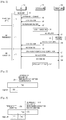
- FIG. 1 illustrates a handover procedure in an LTE system according to the related art.
- the LTE system may include a 3 rd Generation Partnership Project (3GPP) LTE-Advanced (LTE-A) system.
- 3GPP 3 rd Generation Partnership Project
- LTE-A LTE-Advanced
- a UE 110 may report the result to a serving evolved Node B (eNB) 130 of a serving cell, using a measurement report message.
- the serving eNB 130 may determine whether to perform handover, and request handover from a target eNB 150 of a target cell to which the UE 110 is to be handed over.
- the target eNB 150 may determine whether to admit handover of the UE 110 by performing admission control.
- the serving eNB 130 may transmit the information used to perform handover to the UE 110, using a handover command message.
- the UE 110 may perform a handover procedure to the target eNB 150, using the information included in the handover command message, and the UE 110 may terminate the handover procedure after sending a handover confirm message to the target eNB 150.
- reference numerals 11, 13 and 15 represent individual intervals determined by dividing the handover procedure.
- Reference numeral 11 represents a Time To Trigger (TTT) interval in which handover is triggered, and the TTT interval may be maintained while a handover timer TTT is running.
- TTT Time To Trigger
- handover may occur if the signal strength of the target eNB is greater than the signal strength of the serving eNB, meaning that the UE is located at the edge of the serving cell or a channel gain between the UE and the serving eNB is low. Therefore, the handover that occurs because the signal strength of the target eNB is higher than the signal strength of the serving eNB, and the RLF that occurs because the channel gain between the UE and the serving eNB is low, are highly likely to occur together.
- the handover and the RLF are defined through the conditions in the following Table 1.
- N310 is set to a predetermined number of times. As shown in Table 1, if the handover and RLF conditions are maintained for a specified time (e.g., timer TTT, and T310), the handover and RLF may be declared and an operation related thereto may be performed. If the handover and RLF conditions haven't been maintained for the specified time even though the handover and RLF conditions are satisfied, the conditions that have already occurred may be invalid.
- a specified time e.g., timer TTT, and T310
- the handover and the RLF may be the processes that are operated independently. Therefore, if the RLF is declared while the handover procedure is performed, the UE may perform RRC connection reconfiguration regardless of the remaining handover procedure.
- the handover and the RRC connection reconfiguration may cause service disconnection while performing the following operations, respectively.
- the RRC connection reconfiguration compared with the handover, uses additional time for cell search and system information acquisition.
- the cell search and the system information acquisition are operations using a longer time than downlink synchronization, uplink synchronization, and resource allocation. Therefore, it can be noted that when the UE desires to perform communication with a new eNB by performing handover or RRC connection reconfiguration by RLF, the handover is advantageous over the RRC connection reconfiguration in terms of the service disconnection time.
- the frequency of co-occurrence of the handover and the RLF has increased due to the introduction of small cells.
- the reason is as follows.
- the small cell has a small cell coverage area. If the small cells are installed at a high density, the UE may detect multiple small cells and may be subject to interference from them. Therefore, the number of handover areas may increase, and the number of areas where the RLF condition is satisfied due to the inter-cell interference may also increase. To cope with this, an operation of considering the handover and the RLF at the same time has been proposed recently. Details thereof are as follows.
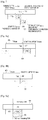
- FIG. 2 illustrates a scheme for early termination of an RLF timer in an LTE system according to the related art.
- the UE may terminate the RLF timer early upon expiration of the handover timer TTT as shown by reference numeral 201, without waiting for the remaining time of the RLF timer until the end, and then perform RRC connection reconfiguration.
- the RLF may occur when the channel gain between the UE and the serving eNB is low, and the RLF may be determined by a Block Error Rate (BLER) of a Physical Downlink Control Channel (PDCCH). Therefore, referring to FIG. 2 , the early termination technique for an RLF timer is to terminate the RLF timer early to reduce the waiting time that is unnecessary in performing RRC connection reconfiguration, determining that the UE is highly unlikely to successfully receive a handover command message from the serving eNB since the RLF timer of the UE has been started.
- BLER Block Error Rate
- PDCH Physical Downlink Control Channel
- the reason why the UE uses (or runs) the RLF timer without directly declaring the RLF is that the channel gain might be likely to get better again during the RLF timer. For this reason, in the early termination technique for an RLF timer according to the related art, the UE may not monitor the situation where the channel gain of the serving cell gets better again. In addition, since the UE performs RRC connection reconfiguration at all times after terminating the RLF timer early, the RLF may undergo a more complex procedure, compared with the RLF which may be automatically recovered.
- the fact that the RLF timer is running means that the channel gain between the UE and the serving eNB is very low on average, but the instantaneous channel gain might be likely to be high by fast fading. If this possibility is taken into consideration, even though the RLF timer is running, the UE is likely to successfully receive a handover command message and successfully perform handover. Therefore, quickly performing RRC connection reconfiguration at all times like in the early termination technique of the related art for an RLF timer T310 may not be considered the best solution.
- T312 timer a new timer called a T312 timer.
- the T312 timer will be referred to herein as a waiting timer.
- the technique for utilizing a waiting timer T312 may operate as follows.
- FIG. 3 illustrates an operation of a proposed waiting timer T312 in an LTE system according to the related art.
- the UE may perform a handover procedure during the waiting timer T312, and if the waiting timer T312 is terminated at time 303, the UE may terminate the RLF timer early without waiting for the remaining time of the RLF timer until the end, and then perform RRC connection reconfiguration.
- the technique for a waiting timer T312 in FIG. 3 has been provided by partially improving the early termination technique for an RLF timer, which has been described in FIG. 2 .
- the early termination technique for an RLF timer in FIG. 2 has not considered the possibility that the channel gain will be recovered again, and the possibility that the UE will successfully receive a handover command message since the instantaneous channel gain is high even though the overage channel gain is low.
- the UE may monitor whether the channel gain is recovered or the handover is successfully performed during the waiting timer T312, even after the handover timer TTT is terminated.
- the UE may terminate the RLF timer early, and then perform RRC connection reconfiguration, thus making it possible to prevent the increase in the service disconnection time of the UE.
- ERICSSON "Fast RLF recovery with new Handover-RLF timer", 3GPP DRAFT; R2-140558 - FAST RLF RECOVERY WITH NEW HANDOVER-RLF TIMER, 3RD GENERATION PARTNERSHIP PROJECT (3GPP), MOBILE COMPETENCE CENTRE ; 650, ROUTE DES LUCIOLES ; F-06921 SOPHIA-ANTIPOLIS CEDEX; vol. RAN WG2, no. Prague, Czech Republic; 20140210 - 20140214, 9 February 2014 , discloses schemes for radio link failure recovery using a timer that is started when a measurement event expiry is triggered and while another timer is running.
- an aspect of the present disclosure is to provide a method and apparatus for efficiently controlling a waiting time for determination of a Radio Link Failure (RLF) in a wireless communication system.
- RLF Radio Link Failure
- Another aspect of the present disclosure is to provide a method and apparatus for efficiently controlling an operation of a waiting timer upon determination of an RLF in a wireless communication system.
- a method for controlling a waiting time related to determination of an RLF in a wireless communication system as claimed in claim 1 is provided.
- a User Equipment for controlling a waiting time related to determination of an RLF in a wireless communication system as claimed in claim 13 is provided.
- LTE Long Term Evolution
- RLF Radio Link Failure
- various embodiments of the present disclosure may be applied to both of the homogeneous network including the same type of cells and the heterogeneous network including different types of cells.
- the heterogeneous network including macro cells and small cells macro-to-macro, macro-to-small, small-to-macro and/or small-to-small cell handovers may occur, and embodiments of the present disclosure may be generally applied regardless of these types of handovers.
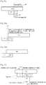
- FIG. 4 illustrates an example of a configuration of a wireless communication system for controlling an operation of a waiting timer T312 according to an embodiment of the present disclosure.
- the UE 470 may detect target eNBs 430 and 450 of target cells 43 and 45 for handover. Examples in FIGS.
- 5 to 12 correspond to proposed operations, namely an operation of the waiting timer T312 when the UE 470 has detected multiple target cells 43 and 45 for handover; an operation of the waiting timer T312, which is performed depending on whether the UE 470 has received a handover-related message; an operation of efficient configuration measures for the start point and length of the waiting timer T312; an operation of terminating the waiting timer T312; and an operation of the waiting timer T312, which is performed depending on the handover event and the entering/leaving condition.
- the number of target cells is assumed to be 2, for convenience of description. However, the present disclosure may be applied in the same way even if two or more target cells are present.
- FIG. 5 illustrates a scheme for controlling a waiting timer T312 when multiple target cells for handover are detected in a wireless communication system according to an embodiment of the present disclosure.
- a UE may detect multiple target cells (or target eNBs) that satisfy a handover condition. Particularly, in the heterogeneous network where multiple small cells are densely installed, more target cells may be detected, compared with in the homogeneous network including only the macro cells.
- the UE may start a handover timer 'a' TTTa by detecting a target cell 'a', and may start a handover timer 'b' TTTb by detecting a target cell 'b' while the handover timer 'a' TTTa is running.
- the UE may start a waiting timer 'a' T312a for the target cell 'a', and if the handover timer 'b' TTTb is terminated at time 503, the UE may start a waiting timer 'b' T312b for the target cell 'b'. If the waiting timer 'a' T312a for the target cell 'a' that the UE has first detected is terminated and the waiting timer T312 follows the above-described general operation, the UE may declare the RLF regardless of the remaining time of the RLF timer T310, and then perform RRC connection reconfiguration.
- the UE may declare the RLF based on the waiting timer T312 for the target cell that is detected later, instead of declaring the RLF based on the waiting timer T312 for the target cell that is detected first.
- the UE may declare the RLF when the waiting timer 'b' T312b for the later detected target cell 'b' is terminated as shown by reference numeral 507, instead of declaring the RLF when the waiting timer 'a' T312a for the first detected target cell 'a' is terminated at time 505 in FIG. 5 .
- the UE may attempt handover to the target cell 'a' until the waiting timer 'b' T312b is terminated, and at the same time, after the handover timer 'b' TTTb is terminated, the UE may attempt handover to the target cell 'b' until the waiting timer 'b' T312b is terminated.
- performing handover is advantageous over performing RRC connection reconfiguration in terms of the service disconnection time. Therefore, if there are multiple handover target eNBs, it is preferable for the UE to have the opportunity to sequentially perform handover to each of the target eNBs. To this end, it is more efficient for the UE to declare the RLF based on the waiting timer 'b' T312b for the later detected target cell 'b' as shown in the example of FIG. 5 .
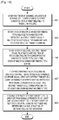
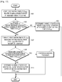
- FIG. 13 is a flowchart illustrating a UE's operation of controlling a waiting timer T312 in accordance with the scheme in FIG. 5 according to an embodiment of the present disclosure.
- the UE may start an RLF timer if the channel situation of the serving cell corresponds to a start condition of the RLF timer.
- the UE may start each of multiple handover timers TTTs related to handover for detected multiple target cells, if the multiple target cells for handover are detected while the RLF timer is running.
- the UE may start each of the multiple waiting timers T312s related to a waiting time of the radio link failure to correspond to the handover timers TTTs, each time each of the multiple handover timers TTTs is terminated.
- the UE may stop the running of the RLF timer, determine (or declare) the channel situation of the serving cell as the RLF situation, and perform RRC connection reconfiguration.
- the UE may newly update (or reset) the running waiting timer T312, each time each of the multiple handover timers TTTs is terminated. If the waiting timer T312 is terminated before the RLF timer is terminated, the UE may stop the running of the RLF timer, determine (or declare) the channel situation of the serving cell as the RLF situation, and perform RRC connection reconfiguration. In order to support this operation, the details (underlined parts) as shown in Table 3 below may be added to Technical Specification (TS) 36.331, 5.5.4.1 Measurement report triggering - General item in the specification for the 3rd Generation Partnership Project (3GPP) LTE system.
- 3GPP 3rd Generation Partnership Project
- the event corresponding with the eventId of the corresponding reportConfig within VarMeasConfig is fulfilled for one or more applicable cells not included in the cellsTriggeredList for all measurements after layer 3 filtering taken during timeToTrigger defined for this event within the VarMeasConfig (a subsequent cell triggers the event) : 3> set the numberOfReportsSent defined within the VadMeasReportList for this meosId to 0; 3> include the concerned cell(s) in the cellsTriggeredList defined within the VarMeasReportList for this measId ; 3> if the event is A3 or A4 or A5 and if the UE supports timer T312 and if the variable useT312-r12 is set for this event and if T310 is running; 4> if T312 is not running; 5> start timer T312 with the value configured in the corresponding measObiectEUTRA ; 4> else; 5> reset timer T312 with the
- the UE when a UE has detected multiple target cells for handover, it is preferable for the UE to perform handover to the target cell that has the best signal strength or quality. Therefore, it is possible to adaptively control the declaration time for the RLF based on the signal strengths of the multiple target cells.
- FIG. 6 illustrates a scheme for controlling a waiting timer T312 based on signal strengths of multiple target cells for handover in a wireless communication system according to an embodiment of the present disclosure.
- the UE may start a handover timer 'a' TTTa by detecting a target cell 'a', and may start a handover timer 'b' TTTb by detecting a target cell 'b' while the handover timer 'a' TTTa is running.
- the UE may start a waiting timer 'a' T312a for the target cell 'a', and if the handover timer 'b' TTTb is terminated at time 603, the UE may start a waiting timer 'b' T312b for the target cell 'b'.
- the UE may determine at time 605 whether the waiting timer 'b' T312b for the target cell 'b' is running, and if the waiting timer 'b' T312b is running, the UE may compare the signal strength of the target cell 'a' with the signal strength of the target cell 'b'.
- the UE may wait until the waiting timer 'b' T312b for the target cell 'b' is terminated, and if the signal strength of the target cell 'b' is less than the signal strength of the target cell 'a', the UE may declare the RLF as soon as the waiting timer 'a' T312a is terminated, without waiting until the waiting timer 'b' T312b for the target cell 'b' is terminated, and then perform RRC connection reconfiguration.
- the scheme in FIG. 6 is efficient in terms of the fact that the UE prefers the handover target eNB having the best signal strength.
- the UE may postpone the RLF declaration, if a handover target eNB having a better signal strength is present at the time the RLF declaration is possible. Otherwise, the UE may immediately declare the RLF. Through this operation, the UE may reduce the handover time, and may quickly start the RRC connection reconfiguration process.
- FIG. 14 is a flowchart illustrating a UE's operation of controlling a waiting timer T312 in accordance with the scheme in FIG. 6 according to an embodiment of the present disclosure.
- the UE may start an RLF timer if the channel situation of the serving cell corresponds to a start condition of the RLF timer.
- the UE may start each of multiple handover timers TTTs related to handover for detected multiple target cells, if the multiple target cells for handover are detected while the RLF timer is running.
- the UE may start each of the multiple waiting timers T312s related to a waiting time of the radio link failure to correspond to the handover timers TTTs, each time each of the multiple handover timers TTTs is terminated.
- the UE may compare the signal strength of a first target cell corresponding to the expired waiting timer T312 with the signal strength of at least one second target cell corresponding to at least one running waiting timer T312. In operation 1409, if the signal strength of the first target cell is greater than the signal strength of the at least one second target cell before the RLF timer is terminated, the UE may stop the running of the RLF timer, determine the channel situation of the serving cell as the RLF situation, and perform RRC connection reconfiguration.
- FIG. 7 illustrates a scheme for controlling a waiting timer T312 depending on whether a handover-related message is received in a wireless communication system according to an embodiment of the present disclosure.
- a UE may send a measurement report message to a serving eNB after expiration of a handover timer TTT, and receive a handover command message from a target eNB. Since the measurement report message is transmitted over an uplink and the handover command message is transmitted over a downlink, the two messages may experience different channel qualities while being transmitted. Therefore, transmission/reception of the two handover-related messages may be considered independent of each other, and a different waiting timer T312 may be applied to each message.
- the waiting timer that is applied when the UE receives Acknowledgement (ACK) for the measurement report message after expiration of the handover timer TTT is defined as T312 MR
- the waiting timer that is applied when the UE receives a handover command message after receiving the ACK for the measurement report message is defined as T312 HOCMD
- the UE may terminate the handover timer TTT and then start T312 MR at time 701 in FIG. 7 .
- the UE fails to receive ACK for the measurement report message during T312 MR , the UE may declare the RLF and perform RRC connection reconfiguration after expiration of T312 MR , at time 703.
- the UE may terminate T312 MR and start T312 HOCMD at time 705. If the UE fails to receive a handover command message during T312 HOCMD , the UE may declare the RLF and perform RRC connection reconfiguration after expiration of T312HOCMD, at time 707. However, if the UE has successfully received a handover command message during T312 HOCMD , the UE may continue the remaining handover process. If T312 MR and T312 HOCMD are separately defined as shown in the example of FIG. 7 , it is possible to separately control the waiting timers depending on the uplink and downlink performances between the UE and the serving eNB.
- FIG. 15 is a flowchart illustrating a UE's operation of separately controlling a waiting timer T312 based on whether a handover-related message is received in accordance with the scheme in FIG. 7 according to an embodiment of the present disclosure.
- the UE may start a first waiting timer T312 MR related to measurement report, if a handover timer TTT expires (or is terminated).
- the UE may determine whether ACK for the measurement report message is received from an eNB while the first waiting timer T312 MR is running. If the UE fails to receive ACK, the UE may determine the channel situation of the serving cell as the RLF situation and perform RRC connection reconfiguration after expiration of the first waiting timer T312 MR , in operation 1505.
- the UE may terminate the first waiting timer T312 MR and start a second waiting timer T312 HOCMD related to reception of the handover command message, in operation 1507.
- the UE may determine whether the handover command message is received while the second waiting timer T312 HOCMD is running. If the UE has received the handover command message, the UE may perform the handover procedure in operation 1511, and if the UE has failed to receive the handover command message, the UE may determine the channel situation of the serving cell as the RLF situation and perform RRC connection reconfiguration after expiration of the second waiting timer T312 HOCMD , in operation 1513.
- FIGS. 8a to 10 to describe a scheme for controlling the start point and length of a waiting timer T312 in various embodiments of the present disclosure.
- the early termination technique for an RLF timer T310 is to allow a UE to immediately declare the RLF upon detection of a handover target eNB and perform RRC connection reconfiguration, in order to reduce the time for which the UE is connected to the serving eNB even though the channel gain with the serving eNB is not good. Therefore, if the early termination technique for an RLF timer T310 is used, it is possible to reduce the time for which the UE is connected to the serving eNB having a poor channel gain, but the UE's opportunity to monitor the recovery of the channel gain of the serving cell may be likely to be reduced. In other words, there is a trade-off relationship between the time for which the UE may experience the low channel gain and the possibility that the channel gain will be recovered.
- the operation control for the waiting timer T312 has been proposed to improve the trade-off relationship.
- this operation control instead of immediately declaring the RLF upon detecting a handover target eNB, the UE may attempt handover while additionally monitoring the channel during the waiting timer T312, and declare the RLF without waiting any longer, if the waiting timer T312 expires.
- the trade-off relationship between the time for which the UE may experience the low channel gain and the possibility that the channel gain will be recovered may still exist depending on the start point and length of the waiting timer T312. Therefore, it is necessary to control the start point and length of the waiting timer T312 taking into account the trade-off relationship between the time for which the UE may experience the low channel gain and the possibility that the channel gain will be recovered.
- FIGS. 8a and 8b illustrate a scheme for controlling a start point of a waiting timer T312 in a wireless communication system according to various embodiments of the present disclosure.
- the UE may immediately start the waiting timer T312 if the handover timer TTT expires. If the handover timer TTT expires at the beginning of the running of the RLF timer T310 as shown in FIG. 8a , a relatively long RLF timer T310 may be left for the UE as shown by reference numeral 801. On the other hand, if the handover timer TTT expires at the middle of the RLF timer T310 as shown in FIG. 8b , a relatively short RLF timer T310 may be left for the UE as shown by reference numeral 803.
- the UE may monitor the channel recovery of the serving eNB and attempt handover only during the waiting timer T312 that starts after expiration of the handover timer TTT. Therefore, in the examples of FIGS. 8a and 8b , in order to ensure the RLF timer T310 of a predetermined time for all UEs, the start point of the waiting timer T312 may be controlled so that the waiting timer T312 may start after a predetermined minimum guaranteed time (T310min) 805 of the RLF timer T310 as shown by reference numeral 807.
- T310min predetermined minimum guaranteed time
- the following operations (1) to (3) are proposed to allow a UE to be guaranteed the RLF timer T310 of a minimum of T310min regardless of the point where the handover timer TTT has expired.
- all UEs may be guaranteed the time for which the channel gain of the serving eNB is recovered and the UEs attempt handover for a predetermined time, after detecting a target cell for handover.
- the present disclosure proposes a scheme for controlling the length of the waiting timer T312 in proportion to the remaining time of the RLF timer T310.
- a UE that has detected a target cell for handover at the beginning of the RLF timer T310 may have the time for which the channel gain of the serving eNB is recovered and the UE attempts handover for a longer time, because the time up to now since the decrease in the channel gain of the serving eNB is still short.
- a UE that has detected a target cell since the middle of the RLF timer T310 may be controlled to have the time for which the channel gain of the serving eNB is recovered and the UE attempts handover for a shorter time, because the time up to now since the decrease in the channel gain of the serving eNB is relatively long.
- FIGS. 9a and 9b illustrate a scheme for controlling a length of a waiting timer T312 in a wireless communication system according to various embodiments of the present disclosure.
- the UE may determine the remaining time (Remaining T310 and Remaining T310') of the RLF timers T310 as shown by reference numerals 901 and 905.
- the UE may determine a length of the waiting timer T312 by multiplying the remaining time (Remaining T310 and Remaining T310') of the RLF timer T310 by a predetermined value as shown by reference numerals 903 and 907. According to an embodiment of the present disclosure, since FIG. 9a is longer than FIG.
- the UE may be controlled so that the time length of the waiting timer T312 in FIG. 9a may be longer than the time length of the waiting timer T312 in FIG. 9b in proportion to the remaining time.
- FIGS. 10a and 10b illustrate another scheme for controlling a start point of a waiting timer T312 in a wireless communication system according to various embodiments of the present disclosure.
- the waiting timer T312 may start only if the handover timer TTT expires while the RLF timer T310 is running. There is no big difference between a case where the handover timer TTT has expired slightly earlier than the RLF timer T310 as shown in FIG. 10a and a case where the handover timer TTT has expired slightly later than the RLF timer T310 as shown in FIG. 10b .
- the waiting timer T312 does not start in the case of FIG. 10a , and the waiting timer T312 starts in the case of FIG. 10b .
- the present disclosure proposes an embodiment shown in FIGS. 10a and 10b .
- the UE may start the handover timer TTT after detecting a handover target eNB.
- the UE may attempt handover, if the handover timer TTT expires after being maintained. If the RLF timer T310 starts due to the low signal quality of the serving eNB, the UE may determine whether the handover timer TTT has expired. If the handover timer TTT has expired before the start of the RLF timer T310 as shown in FIG. 10a , the UE may determine the expiration time of the handover timer TTT.
- the UE may start the waiting timer T312 at the start time of the RLF timer T310. If the difference 1001 between the expiration time of the handover timer TTT and the start time of the RLF timer T310 is greater than the threshold, the UE may not apply the technique for a waiting timer T312 and the early termination technique for an RLF timer T310. If these operations are applied, the UE may start the waiting timer T312 even though the handover timer TTT has expired before the start of the RLF timer T310.
- the case in FIG. 10b is the same case as the above examples in which the UE immediately starts the waiting timer T312 after the expiration of the handover timer TTT.
- the UE may declare the RLF regardless of the remaining time of the RLF timer T310, and perform RRC connection reconfiguration.
- the present disclosure proposes a control scheme of terminating the waiting timer T312 during its running, if a predetermined termination condition is satisfied.
- the termination conditions of the waiting timer T312, which are proposed in an embodiment of the present disclosure, may include:
- condition (1) if the UE successfully sends a measurement report message to the serving eNB, the serving eNB may send a handover request message to its neighboring eNBs.
- a neighboring eNB that has received the handover request message may be aware of the fact that the UE will be connected to the neighboring eNB itself soon. Therefore, in a case where the UE has successfully sent the measurement report message, even though the UE performs RRC connection reconfiguration, it is possible to reduce the time for RRC connection reconfiguration. In this case, the UE may terminate the waiting timer T312 and perform RRC connection reconfiguration.
- condition (2) and condition (3) it is not necessary to maintain the waiting timer T312, since the handover is being performed smoothly and the channel gain between the UE and the serving eNB has been recovered. Therefore, the UE may terminate the waiting timer T312.
- Condition (4) will be described with reference to Table 4 below.
- some events A1 to A6 are defined as shown in Table 4, so if the signal strength or quality of the UE satisfies at least one of the following events, the UE may report the measurement result to the serving eNB.
- a message used for the report is a measurement report message, and the serving eNB that has received the measurement report message may determine whether to perform handover of the UE.
- the events in Table 4 are defined in the specifications of the 3GPP LTE system.
- events A1 and A2 are not related to the signal strength or quality for neighboring eNBs. These events may be less related to the early termination technique for an RLF timer T310 and the utilizing technique for a waiting timer T312. The reason is that even though the UE early terminates the RLF timer T310, the UE has not discovered the neighboring eNB to which the UE will perform RRC connection reconfiguration.
- an event A6 considers only the signal strength or quality of a Secondary Cell (SCell), and does not consider the signal strength or quality of a Primary Cell (PCell).
- SCell Secondary Cell
- PCell Primary Cell
- This case may also be less related to the early termination technique for an RLF timer T310 and the technique for a waiting timer T312.
- the reason is that according to the specifications of the 3GPP LTE system, which have been published up to now, the UE does not declare the RLF for the SCell. However, if the UE declares the RLF even for the SCell as the specifications of the 3GPP LTE system are changed in the future, the event A6 may also be highly related to the early termination technique for an RLF timer T310 and the technique for a waiting timer T312.
- the technique for a waiting timer T312 may be applied when the RLF timer T310 is running (i.e., the signal quality of the serving eNB is not good). Therefore, the technique for a waiting timer T312 is highly likely to be applied to the handover event in which neighboring eNBs are taken into consideration. In other words, the technique for a waiting timer T312 is highly likely to be applied to the events A3, A4 and A5 in which the signal strength or quality of the neighboring eNBs are taken into consideration. Therefore, in an embodiment of the present disclosure, the eNB may inform the UE whether to apply the technique for a waiting timer T312, when the UE has satisfied a specific event.
- FIG. 16 is a flowchart illustrating a UE's operation of controlling a waiting timer T312 when the UE satisfies a specific event according to an embodiment of the present disclosure.
- the UE may start the RLF timer if the channel situation of the serving cell corresponds to a start condition of the RLF timer.
- the UE may determine in operation 1605 whether the specific event supports the technique for a waiting timer T312. If the specific event supports the technique for a waiting timer T312, the UE may start the waiting timer T312 by applying the technique for a waiting timer T312 in operation 1607.
- the UE may determine the presence/absence of the RLF in a manner according to the related art.
- the UE may apply the technique for a waiting timer T312 (i.e., may start the waiting timer T312). However, if the UE has satisfied another specific event, the UE may not apply the technique for a waiting timer T312 (i.e., may not start the waiting timer T312).
- the details as shown in Tables 5 to 7 below may be added to TS 36.331, 5.5.4.1 Measurement report triggering General item, and MeasObjectEUTRA information element, and ReportConfigEUTRA information element items in the specification for the 3GPP LTE system.
- MeasObjectEUTRA information element and ReportConfigEUTRA information element may be included in an RRC message (e.g., an RRC connection (re)configuration message) that is sent from the eNB to the UE in Evolved Universal Terrestrial Radio Access Network (EUTRAN) as known in the 3GPP LTE standard.
- the RRC connection (re)configuration message may be sent from the eNB to the UE, for (re)configuration of an RRC connection such as resource allocation/de-allocation, handover, measurement configuration, and cell addition/release.
- the information for supporting the technique for a waiting timer T312, which is proposed in an embodiment of the present disclosure, may be provided to the UE through the MeasObjectEUTRA information element and ReportConfigEUTRA information element, and the UE may receive the waiting timer information through an RRC message before occurrence of the specific event.
- the UE since the UE should know when and what the UE should measure, the UE may receive an RRC connection (re)configuration message including the waiting timer information before occurrence of the running of the RLF timer T310 and the expiration of the handover timer TTT.
- the waiting timer information may include at least one of information indicating support/non-support of the waiting timer T312 in the network and a configured value for the waiting timer T312.
- ReportConfigEUTRA information element may include information indicating support/non-support of the waiting timer T312.
- MeasObjectEUTRA information element may include a configured value for the waiting timer T312. The configured value may be construed as a configured time of the waiting timer T312. The configured value for the waiting timer T312 may be individually configured for each event as illustrated in Table 6.
- 3> initiate the measurement reporting procedure, as specified in 5.5.5; 2> if the triggerType is set to event and if the entry condition applicable for this event, i.e. the event corresponding with the eventId of the corresponding reportConfig within VarMeasConfig.
- 3> set the numberOfReportsSent defined within the VarMeasReportList for this measId to 0; 3> include the concerned cell(s) in the cellsTriggeredList defined within the VarMeasReportList for this measId: 3> if the UE supports T312 and if useT312-r12 is included for this event and if T310 is running; 4> if T312 is not running; 5> start timer T312 with the value configured in the corresponding memObject ; 3> initiate the measurement reporting procedure, as specified in 5.5.5;
- MeasObjectEUTRA MeasObjectEUTRA information element [[t312-r12 ENUMERATED (ms0, ms50, ms100, ms200, ms300, ms400, ms500, ms1000 ⁇ OPTIONAL,Need ON]] MeasObjectEUTRA field descriptions t312-r12 The value of timer T312. Value ms0 represents 0 ms 50ms represents 50 ms and so on.
- the known events A1 to A6 defined in the specifications of the 3GPP LTE system may have handover entering condition and leaving condition as shown in Tables 8 to 13 below.
- Ms is the measurement result of the serving cell, not taking into account any offsets
- Hys is the hysteresis parameter for this event (i.e. hysteresis as defined within reportConfigEUTRA for this event).
- Thresh is the threshold parameter for this event (i.e. a1-ThreShold as defined within reportConfigEUTRA for this event).
- Ms is expressed in dBm in case of RSRP, or in dB in case of RSRQ.
- Hys is expressed in dB.
- Thresh is expressed in the same unit as Ms.
- Table 8 shows the handover entering and leaving conditions for the event A1.
- Ms is the measurement result of the serving cell, not taking into account any offsets.
- Hys is the hysteresis parameter for this event (i.e. hysteresis as defined within reportConfigEUTRA for this event).
- Thresh is the threshold parameter for this event (i.e. a2-Threshold as defined within reportConfigEUTRA for this event).
- Ms is expressed in dBm in case of RSRP, or in dB in case of RSRQ.
- Hys is expressed in dB.
- Thresh is expressed in the same unit as Ms .
- Table 9 shows the handover entering and leaving conditions for the event A2.
- Hys is the hysteresis parameter for this event Off is the offset parameter for this event Mn, Mp arc expressed in dBm in case of RSRP, or in dB in case of RSRQ. Ofn, Ocn, Ofp, Ocp, Hys, Off are expressed in dB.
- Table 10 shows the handover entering and leaving conditions for the event A3.
- Table 11 shows the handover entering and leaving conditions for the event A4.
- Thresh 1 is the threshold parameter for this event
- Thresh 2 is the threshold parameter for this event Mn
- Mp are expressed in dBm in case of RSRP, or in dB in case of RSRQ Ofn, Ocn, Hys are expressed in dB.
- Thresh1 is expressed in the same unit as Mp .
- Thresh2 is expressed in the same unit as Mn .
- Table 12 shows the handover entering and leaving conditions for the event A5.
- Mn is the measurement result of the neighbouring cell. not taking into account any offsets.
- Ocn is the cell specific offset of the neighbour cell (i.e. cellIndividualOffset as defined within measObjectEUTRA corresponding to the frequency of the neighbour cell), and set to zero if not configured for the neighbour cell.
- Ms is the measurement result of the serving cell, not taking into account any offsets.
- Ocs is the cell specific offset of the serving cell (i.e.
- Hys is the hysteresis parameter for this event (i.e. hysteresis as defined within reportConfigEUTRA for this event).
- Off is the offset parameter for this event (i.e. a6-Offset as defined within reportConfigEUTRA for this event).
- Mn Ms are expressed in dBm in case of RSRP. or in dB in case of RSRQ.
- Ocn, Ocs, Hys, Off are expressed in dB.
- Table 13 represents handover entering and leaving conditions for the event A6.
- the UE may send a measurement report message to the serving eNB to request initiation of handover.
- the UE may send a measurement report message to the serving eNB to request termination of the ongoing handover.
- operations of the UE and the eNB may be distinguished depending on whether the measurement report message is a measurement report message that is sent as the measured signal strength or quality satisfies the handover entering condition, or a measurement report message that is sent as the measured signal strength or quality satisfies the handover leaving condition.
- the basic operation of the technique for a waiting timer T312 may start the waiting timer T312 regardless of which condition the measurement report message satisfies when the message is sent. If the UE satisfies an entering condition for a specific event and the event is an event to which the technique for a waiting timer T312 is applied, it is preferable for the UE to start the waiting timer T312. However, if the UE satisfies a leaving condition and has sent a measurement report message, the UE may consider the following situation.
- FIG. 11 illustrates a scheme for controlling a waiting timer T312 based on a handover leaving condition in a wireless communication system according to an embodiment of the present disclosure.
- the UE may start the RLF timer T310 as the UE satisfies a start condition of the RLF timer T310, and the UE may start and maintain the handover timer TTT at time 1101 as the UE satisfies a handover entering condition for a specific handover event with respect to a target cell 'a'.
- the UE may start the waiting timer T312 at time 1103 after expiration of the handover timer TTT.
- the UE may satisfy the handover leaving condition at time 1105 for a specific handover event with respect to the target cell 'a' during the handover timer TTT in the interval of the waiting timer T312.
- the target cell 'a' may be no longer an appropriate handover target cell from the perspective of the UE. Therefore, even though the UE declares the RLF and performs RRC connection reconfiguration after expiration of the waiting timer T312, there may be no neighboring eNBs to which the UE will perform RRC connection reconfiguration. Therefore, instead of declaring the RLF and performing RRC connection reconfiguration after terminating the waiting timer T312, it may be preferable for the UE to terminate the running waiting timer T312 and wait for the situation where the channel of the serving eNB is getting better, while waiting for the RLF timer T310.
- the UE may immediately terminate the waiting timer T312, if the UE satisfies the handover leaving condition for the target cell 'a' during the handover timer TTT as shown by reference numeral 1107 in FIG. 11 .
- FIG. 17 is a flowchart illustrating a UE's operation of controlling a waiting timer T312 based on a handover leaving condition in a wireless communication system according to an embodiment of the present disclosure.
- the UE may start the RLF timer if the channel situation of the serving cell corresponds to a start condition of the RLF timer related to the RLF.
- the UE may start the handover timer TTT related to handover for a detected target cell, if a target cell for handover is detected while the RLF timer is running.
- the UE may start the waiting timer T312 related to the waiting time of the RLF.
- the UE may terminate the waiting timer T312 and monitor the channel situation of the serving cell while the RLF timer is running.
- FIG. 12 illustrates another scheme for controlling a waiting timer T312 based on a handover leaving condition in a wireless communication system according to an embodiment of the present disclosure.
- the UE may start the RLF timer T310 as the UE satisfies a start condition of the RLF timer T310.
- the UE may start and maintain a handover timer 'a' TTTa, as the UE satisfies the handover entering condition for a specific handover event with respect to a target cell 'a'.
- the UE may start and maintain a handover timer 'b' TTTb, as the UE satisfies the handover entering condition for a specific handover event with respect to a target cell 'b'.
- the UE may start the waiting timer T312 after expiration of the handover timer 'a' TTTa for the target cell 'a'.
- the target cell 'b' may be no longer an appropriate handover target cell from the perspective of the UE.
- the target cell 'a' may be still a proper handover target cell, since the handover leaving condition hasn't been satisfied after the satisfaction of the handover entering condition.
- the waiting timer T312 should be kept. Therefore, in this embodiment of the present disclosure, even though the UE satisfies the handover leaving condition at time 1211 for a specific handover event with respect to the target cell 'b' during the handover timer TTT, the UE may maintain the waiting timer T312a at time 1213 for the target cell 'a' without terminating the waiting timer T312a, if the UE now satisfies the handover entering condition for the specific handover event and there is the target cell 'a' for which the UE maintains the handover timer TTT.
- the UE may maintain the running waiting timer T312, and if there is no other eNB that satisfies an entering condition and maintains the entering condition, the UE may terminate the waiting timer T312.
- the UE may periodically send a measurement report message to the eNB, even though the above events A1 to A6 do not occur.
- the technique for a waiting timer T312 may not be applied in an embodiment of the preset disclosure. In other words, the UE may not start the waiting timer T312 with respect to the periodic measurement report message.
- the length of the waiting timer T312 may be different depending on the type of the target cell for handover of the UE. For example, as shown in Table 14 below, if the target cell is a pico cell, a waiting timer T312_Pico, a length of which is configured as a relatively small value, may be used, and if the target cell is a macro cell, a waiting timer T312_Macro, a length of which is configured as a relatively large value, may be used (T312_Macro > T312_Pico).
- Information about the waiting timer T312_Pico or T312_Macro that has a different length depending on the type of the target cell may be transmitted to the UE by the eNB in a unicast manner, a broadcast manner, or another predetermined manner.
- the length of the waiting timer T312 may be determined depending on (or in proportion to) the length of the handover timer TTT to which the ongoing handover is applied. For example, if the handover timer TTT has a large value, the waiting timer T312 may also have a large value, and if the handover timer TTT has a small value, the waiting timer T312 may also have a small value. It is also possible to classify the handover timer TTT for each interval, and then cause the waiting timer T312 to correspond to each interval.
- the waiting timers T312 may correspond to 50, 100, 150, 200 and 250 ms, in each interval.
- 'a' is a scaling parameter
- the eNB may transmit information about the scaling parameter 'a' to the UE in a unicast manner, a broadcast manner, or another predetermined manner.
- the waiting timer T312 uses the signal strength (e.g., Reference Signal Received Power (RSRP)) of the target cell to which the UE performs handover.
- the waiting timer T312 may be configured such that if RSRP of the target cell is high, the waiting timer T312 may have a small value and if RSRP of the target cell is low, the waiting timer T312 may have a large value.
- it is also possible to configure the waiting timer T312 by scaling the RLF timer T310 in the manner of (T312 b*T310).
- RSRPtarget is RSRP of the target cell.
- its information may be transmitted to the UE by the eNB in a unicast manner or a broadcast manner, or a predetermined value may be used.
- RSRP of the target cell may be classified for each interval as shown in Table 16 below, and it is also possible to cause the waiting timer T312 to correspond to each interval.
- the waiting timer T312 uses the ratio (RSRPtarget/RSRPserving) (hereinafter, referred to as an 'RSRP ratio') between RSRP of the target cell to which the UE performs handover, and RSRP of the current serving cell.
- the waiting timer T312 may be configured such that if the RSRP ratio has a large value, the waiting timer T312 may have a small value, and if the RSRP ratio has a small value, the waiting timer T312 may have a large value.
- the UE may configure the waiting timer T312 that the UE itself will use, by multiplying the maximum waiting timer T312, a value of which is received from the eNB in a unicast manner or a broadcast manner, or a value of which is known in a predetermined manner, by the RSRP ratio.
- FIG. 18 illustrates a scheme for configuring a waiting timer T312 according to an embodiment of the present disclosure.
- the UE may configure the waiting timer T312 1803 by multiplying the remaining RLF timer T310 1807 by the RSRP ratio.
- reference numeral 1801 represents the handover timer TTT
- reference numeral 1805 represents the RLF timer T310.
- FIG. 19 illustrates a configuration of a UE controlling an operation of a waiting timer T312 according to an embodiment of the present disclosure.
- the UE in FIG. 19 may be implemented to include a transceiver 1910 for transmitting and receiving data to/from an eNB of each cell, a measurer 1930 for measuring the signal strength of each cell for cell search for handover, and a controller 1950 for controlling an operation of the waiting timer T312 by applying at least one of the schemes described in FIGS. 4 to 18 .
- various embodiments of the present disclosure correspond to the solutions to various situations, which occur when the technique for a waiting timer T312 is used, which enables the waiting timer T312 to smoothly operate and to have a framework for optimizing the technique for a waiting timer T312, in the LTE system.
- various embodiments of the present disclosure may prevent the decrease in handover opportunities while reducing the service disconnection time if possible, which may occur when the UE experiences the handover and the RLF at the same time.
Description
- The present disclosure relates to a method and apparatus for controlling an operation of a timer related to Radio Link Failure (RLF) in relation to handover in a wireless communication system.
- In a wireless communication system, the channel status to a serving cell is generally changed from time to time depending on the movement or communication environment of a User Equipment (UE), and if the channel status of the serving cell is not good, the UE may declare Radio Link Failure (RLF) to perform Radio Resource Control (RRC) connection reconfiguration, or may detect (or search for) a target cell for handover among the neighboring cells to perform a handover procedure.
- First, a handover procedure in a Long Term Evolution (LTE) system that is an example of the wireless communication system will be described.
-
FIG. 1 illustrates a handover procedure in an LTE system according to the related art. Herein, the LTE system may include a 3rd Generation Partnership Project (3GPP) LTE-Advanced (LTE-A) system. - Referring to
FIG. 1 , inoperations 101 to 107, if aUE 110 detects a handover event by measuring the strength (e.g., Reference Signal Received Power (RSRP)) of a downlink signal, theUE 110 may report the result to a serving evolved Node B (eNB) 130 of a serving cell, using a measurement report message. Inoperations 109 to 119, the servingeNB 130 may determine whether to perform handover, and request handover from atarget eNB 150 of a target cell to which theUE 110 is to be handed over. Thetarget eNB 150 may determine whether to admit handover of theUE 110 by performing admission control. If handover of theUE 110 is admitted, the servingeNB 130 may transmit the information used to perform handover to theUE 110, using a handover command message. Inoperations 121 to 127, theUE 110 may perform a handover procedure to thetarget eNB 150, using the information included in the handover command message, and theUE 110 may terminate the handover procedure after sending a handover confirm message to thetarget eNB 150. Referring toFIG. 1 ,reference numerals Reference numeral 11 represents a Time To Trigger (TTT) interval in which handover is triggered, and the TTT interval may be maintained while a handover timer TTT is running. - Generally, in the wireless communication system, handover may occur if the signal strength of the target eNB is greater than the signal strength of the serving eNB, meaning that the UE is located at the edge of the serving cell or a channel gain between the UE and the serving eNB is low. Therefore, the handover that occurs because the signal strength of the target eNB is higher than the signal strength of the serving eNB, and the RLF that occurs because the channel gain between the UE and the serving eNB is low, are highly likely to occur together. In the LTE system, the handover and the RLF are defined through the conditions in the following Table 1.
-
[Table 1] Conditions Condition maintaining time (timer) Handover RSRPtarget > RSRPserving + Δ TTT (time-to-trigger) RLF 'BLERPDCCH < BLERthreshold' has occurred N310 times (out-of-sync indication is received N310 times) T310 - In Table 1, "N310" is set to a predetermined number of times. As shown in Table 1, if the handover and RLF conditions are maintained for a specified time (e.g., timer TTT, and T310), the handover and RLF may be declared and an operation related thereto may be performed. If the handover and RLF conditions haven't been maintained for the specified time even though the handover and RLF conditions are satisfied, the conditions that have already occurred may be invalid.
- Basically, the handover and the RLF may be the processes that are operated independently. Therefore, if the RLF is declared while the handover procedure is performed, the UE may perform RRC connection reconfiguration regardless of the remaining handover procedure. The handover and the RRC connection reconfiguration may cause service disconnection while performing the following operations, respectively.
-
[Table 2] Operations Handover Downlink synchronization → uplink synchronization → resource allocation RRC connection reconfiguration Cell search → downlink synchronization → system information acquisition → uplink synchronization → resource allocation - As shown in Table 2, the RRC connection reconfiguration, compared with the handover, uses additional time for cell search and system information acquisition. Generally, the cell search and the system information acquisition are operations using a longer time than downlink synchronization, uplink synchronization, and resource allocation. Therefore, it can be noted that when the UE desires to perform communication with a new eNB by performing handover or RRC connection reconfiguration by RLF, the handover is advantageous over the RRC connection reconfiguration in terms of the service disconnection time.
- In a heterogeneous network including various types of cells, the frequency of co-occurrence of the handover and the RLF has increased due to the introduction of small cells. The reason is as follows. First, the small cell has a small cell coverage area. If the small cells are installed at a high density, the UE may detect multiple small cells and may be subject to interference from them. Therefore, the number of handover areas may increase, and the number of areas where the RLF condition is satisfied due to the inter-cell interference may also increase. To cope with this, an operation of considering the handover and the RLF at the same time has been proposed recently. Details thereof are as follows.
-
FIG. 2 illustrates a scheme for early termination of an RLF timer in an LTE system according to the related art. - Referring to
FIG. 2 , while an RLF timer T310 is running, if a handover timer TTT is started, maintained and terminated (or expired), the UE may terminate the RLF timer early upon expiration of the handover timer TTT as shown byreference numeral 201, without waiting for the remaining time of the RLF timer until the end, and then perform RRC connection reconfiguration. - As described above, the RLF may occur when the channel gain between the UE and the serving eNB is low, and the RLF may be determined by a Block Error Rate (BLER) of a Physical Downlink Control Channel (PDCCH). Therefore, referring to
FIG. 2 , the early termination technique for an RLF timer is to terminate the RLF timer early to reduce the waiting time that is unnecessary in performing RRC connection reconfiguration, determining that the UE is highly unlikely to successfully receive a handover command message from the serving eNB since the RLF timer of the UE has been started. - However, the reason why the UE uses (or runs) the RLF timer without directly declaring the RLF is that the channel gain might be likely to get better again during the RLF timer. For this reason, in the early termination technique for an RLF timer according to the related art, the UE may not monitor the situation where the channel gain of the serving cell gets better again. In addition, since the UE performs RRC connection reconfiguration at all times after terminating the RLF timer early, the RLF may undergo a more complex procedure, compared with the RLF which may be automatically recovered.
- In addition, the fact that the RLF timer is running means that the channel gain between the UE and the serving eNB is very low on average, but the instantaneous channel gain might be likely to be high by fast fading. If this possibility is taken into consideration, even though the RLF timer is running, the UE is likely to successfully receive a handover command message and successfully perform handover. Therefore, quickly performing RRC connection reconfiguration at all times like in the early termination technique of the related art for an RLF timer T310 may not be considered the best solution.
- Therefore, in order to address the disadvantages of the early termination technique for an RLF timer, a new timer called a T312 timer has been introduced. For convenience, the T312 timer will be referred to herein as a waiting timer. The technique for utilizing a waiting timer T312 may operate as follows.
-
FIG. 3 illustrates an operation of a proposed waiting timer T312 in an LTE system according to the related art. - Referring to
FIG. 3 , while the RLF timer T310 is running, if the handover timer TTT is started, and then terminated attime 301, the UE may perform a handover procedure during the waiting timer T312, and if the waiting timer T312 is terminated attime 303, the UE may terminate the RLF timer early without waiting for the remaining time of the RLF timer until the end, and then perform RRC connection reconfiguration. The technique for a waiting timer T312 inFIG. 3 has been provided by partially improving the early termination technique for an RLF timer, which has been described inFIG. 2 . - The early termination technique for an RLF timer in
FIG. 2 has not considered the possibility that the channel gain will be recovered again, and the possibility that the UE will successfully receive a handover command message since the instantaneous channel gain is high even though the overage channel gain is low. However, by introducing the waiting timer T312 as shown inFIG. 3 , the UE may monitor whether the channel gain is recovered or the handover is successfully performed during the waiting timer T312, even after the handover timer TTT is terminated. In addition, if the waiting timer T312 is terminated, the UE may terminate the RLF timer early, and then perform RRC connection reconfiguration, thus making it possible to prevent the increase in the service disconnection time of the UE. - However, as to the technique for a waiting timer T312, there are no specific proposed measures for determining by which scheme the UE will operate the waiting timer T312 in various situations which may occur in the network. Therefore, the measures to control the waiting timer T312 more efficiently are desired.
- The above information is presented as background information only to assist with an understanding of the present disclosure. No determination has been made, and no assertion is made, as to whether any of the above might be applicable as prior art with regard to the present disclosure.
ERICSSON: "Fast RLF recovery with new Handover-RLF timer", 3GPP DRAFT; R2-140558 - FAST RLF RECOVERY WITH NEW HANDOVER-RLF TIMER, 3RD GENERATION PARTNERSHIP PROJECT (3GPP), MOBILE COMPETENCE CENTRE ; 650, ROUTE DES LUCIOLES ; F-06921 SOPHIA-ANTIPOLIS CEDEX; vol. RAN WG2, no. Prague, Czech Republic; 20140210 - 20140214, 9 February 2014, discloses schemes for radio link failure recovery using a timer that is started when a measurement event expiry is triggered and while another timer is running. - Aspects of the present disclosure are to address at least the above-mentioned problems and/or disadvantages and to provide at least the advantages described below. Accordingly, an aspect of the present disclosure is to provide a method and apparatus for efficiently controlling a waiting time for determination of a Radio Link Failure (RLF) in a wireless communication system.
- Another aspect of the present disclosure is to provide a method and apparatus for efficiently controlling an operation of a waiting timer upon determination of an RLF in a wireless communication system.
- In accordance with an aspect of the present disclosure, a method for controlling a waiting time related to determination of an RLF in a wireless communication system as claimed in claim 1 is provided.
- In accordance with another aspect of the present disclosure, a User Equipment (UE) for controlling a waiting time related to determination of an RLF in a wireless communication system as claimed in
claim 13 is provided. - Other aspects, advantages, and salient features of the disclosure will become apparent to those skilled in the art from the following detailed description, which, taken in conjunction with the annexed drawings, discloses various embodiments of the present disclosure.
- The above and other aspects, features, and advantages of certain embodiments of the present disclosure will be more apparent from the following description taken in conjunction with the accompanying drawings, in which:
-
FIG. 1 illustrates a handover procedure in a Long Term Evolution (LTE) system according to the related art; -
FIG. 2 illustrates a scheme for early termination of a Radio Link Failure (RLF) timer in an LTE system according to the related art; -
FIG. 3 illustrates an operation of a proposed waiting timer T312 in an LTE system according to the related art; -
FIG. 4 illustrates an example of a configuration of a wireless communication system for controlling an operation of a waiting timer T312 according to an embodiment of the present disclosure; -
FIG. 5 illustrates a scheme for controlling a waiting timer T312 when multiple target cells for handover are detected in a wireless communication system according to an embodiment of the present disclosure; -
FIG. 6 illustrates a scheme for controlling a waiting timer T312 based on signal strengths of multiple target cells for handover in a wireless communication system according to an embodiment of the present disclosure; -
FIG. 7 illustrates a scheme for controlling a waiting timer T312 depending on whether a handover-related message is received in a wireless communication system according to an embodiment of the present disclosure; -
FIGS. 8a and 8b illustrate a scheme for controlling a start point of a waiting timer T312 in a wireless communication system according to various embodiments of the present disclosure; -
FIGS. 9a and9b illustrate a scheme for controlling a length of a waiting timer T312 in a wireless communication system according to various embodiments of the present disclosure; -
FIGS. 10a and 10b illustrate another scheme for controlling a start point of a waiting timer T312 in a wireless communication system according to various embodiments of the present disclosure; -
FIG. 11 illustrates a control scheme based on a termination condition of a waiting timer T312 in a wireless communication system according to an embodiment of the present disclosure; -
FIG. 12 illustrates another scheme for controlling a waiting timer T312 based on a handover leaving condition in a wireless communication system according to an embodiment of the present disclosure; -
FIG. 13 is a flowchart illustrating a User Equipment's (UE's) operation of controlling a waiting timer T312 in accordance with the scheme inFIG. 5 according to an embodiment of the present disclosure; -
FIG. 14 is a flowchart illustrating a UE's operation of controlling a waiting timer T312 in accordance with the scheme inFIG. 6 according to an embodiment of the present disclosure; -
FIG. 15 is a flowchart illustrating a UE's operation of separately controlling a waiting timer T312 based on whether a handover-related message is received in accordance with the scheme inFIG. 7 according to an embodiment of the present disclosure; -
FIG. 16 is a flowchart illustrating a UE's operation of controlling a waiting timer T312 when the UE satisfies a specific event according to an embodiment of the present disclosure; -
FIG. 17 is a flowchart illustrating a UE's operation of controlling a waiting timer T312 based on a handover leaving condition in a wireless communication system according to an embodiment of the present disclosure; -
FIG. 18 illustrates a scheme for configuring a waiting timer T312 according to an embodiment of the present disclosure; and -
FIG. 19 illustrates a configuration of a UE controlling an operation of a waiting timer T312 according to an embodiment of the present disclosure. - Throughout the drawings, like reference numerals will be understood to refer to like parts, components, and structures.
- The following description with reference to the accompanying drawings is provided to assist in a comprehensive understanding of various embodiments of the present disclosure as defined by the claims. It includes various specific details to assist in that understanding but these are to be regarded as merely exemplary. Accordingly, those of ordinary skill in the art will recognize that various changes and modifications of the various embodiments described herein can be made without departing from the scope of the present disclosure. In addition, descriptions of well-known functions and constructions may be omitted for clarity and conciseness.
- The terms and words used in the following description and claims are not limited to the bibliographical meanings, but, are merely used by the inventor to enable a clear and consistent understanding of the present disclosure. Accordingly, it should be apparent to those skilled in the art that the following description of various embodiments of the present disclosure is provided for illustration purpose only and not for the purpose of limiting the present disclosure as defined by the appended claims.
- It is to be understood that the singular forms "a," "an," and "the" include plural referents unless the context clearly dictates otherwise. Thus, for example, reference to "a component surface" includes reference to one or more of such surfaces.
- By the term "substantially" it is meant that the recited characteristic, parameter, or value need not be achieved exactly, but that deviations or variations, including for example, tolerances, measurement error, measurement accuracy limitations and other factors known to those of skill in the art, may occur in amounts that do not preclude the effect the characteristic was intended to provide.
- Although various embodiments of the present disclosure will be described with reference to, for example, a Long Term Evolution (LTE) system, the various embodiments of the present disclosure may be applied to various other wireless communication systems that can use or run a waiting timer upon determination of a Radio Link Failure (RLF), in the same way.
- In addition, various embodiments of the present disclosure may be applied to both of the homogeneous network including the same type of cells and the heterogeneous network including different types of cells. For example, in the heterogeneous network including macro cells and small cells, macro-to-macro, macro-to-small, small-to-macro and/or small-to-small cell handovers may occur, and embodiments of the present disclosure may be generally applied regardless of these types of handovers.
- First, for a better understanding of the present disclosure, the general operation of the waiting timer T312 will be described as operations (1) to (5) below.
- (1) If the situation where a channel gain between the UE and the serving evolved Node B (eNB) is low and Block Error Rate (BLER)PDCCH is lower than BLERthreshold (i.e., the block error rate BLERPDCCH of a Physical Downlink Control Channel (PDCCH) is lower than a predetermined threshold BLERthreshold in the LTE system) occurs a predetermined number of times, the RLF timer T310 may be started.
- (2) If the User Equipment (UE) detects a target eNB that satisfies a handover condition, the handover timer Time To Trigger (TTT) may be started.
- (3) If the handover timer TTT is terminated, the waiting timer T312 may be started.
- (4) The UE may attempt handover until the waiting timer T312 is terminated.
- (5) If the waiting timer T312 is terminated, the UE may declare the RLF regardless of the remaining RLF timer T310, and perform Radio Resource Control (RRC) connection reconfiguration.
-
FIG. 4 illustrates an example of a configuration of a wireless communication system for controlling an operation of a waiting timer T312 according to an embodiment of the present disclosure. - Referring to
FIG. 4 , if a handover event occurs while aUE 470 is performing communication with a servingeNB 410 of a servingcell 41, theUE 470 may detecttarget eNBs target cells FIGS. 5 to 12 correspond to proposed operations, namely an operation of the waiting timer T312 when theUE 470 has detectedmultiple target cells UE 470 has received a handover-related message; an operation of efficient configuration measures for the start point and length of the waiting timer T312; an operation of terminating the waiting timer T312; and an operation of the waiting timer T312, which is performed depending on the handover event and the entering/leaving condition. In the examples ofFIGS. 4 to 12 , the number of target cells is assumed to be 2, for convenience of description. However, the present disclosure may be applied in the same way even if two or more target cells are present. -
FIG. 5 illustrates a scheme for controlling a waiting timer T312 when multiple target cells for handover are detected in a wireless communication system according to an embodiment of the present disclosure. - In the actual network environment, a UE may detect multiple target cells (or target eNBs) that satisfy a handover condition. Particularly, in the heterogeneous network where multiple small cells are densely installed, more target cells may be detected, compared with in the homogeneous network including only the macro cells.
- Referring to
FIG. 5 , a situation where there are two target cells for handover is illustrated. First, the UE may start a handover timer 'a' TTTa by detecting a target cell 'a', and may start a handover timer 'b' TTTb by detecting a target cell 'b' while the handover timer 'a' TTTa is running. In addition, if the handover timer 'a' TTTa is terminated attime 501, the UE may start a waiting timer 'a' T312a for the target cell 'a', and if the handover timer 'b' TTTb is terminated attime 503, the UE may start a waiting timer 'b' T312b for the target cell 'b'. If the waiting timer 'a' T312a for the target cell 'a' that the UE has first detected is terminated and the waiting timer T312 follows the above-described general operation, the UE may declare the RLF regardless of the remaining time of the RLF timer T310, and then perform RRC connection reconfiguration. - In the example of
FIG. 5 , unlike in the general operation of the waiting timer T312, if there are multiple handover target eNBs, the UE may declare the RLF based on the waiting timer T312 for the target cell that is detected later, instead of declaring the RLF based on the waiting timer T312 for the target cell that is detected first. In other words, the UE may declare the RLF when the waiting timer 'b' T312b for the later detected target cell 'b' is terminated as shown byreference numeral 507, instead of declaring the RLF when the waiting timer 'a' T312a for the first detected target cell 'a' is terminated attime 505 inFIG. 5 . After the handover timer 'a' TTTa is terminated, the UE may attempt handover to the target cell 'a' until the waiting timer 'b' T312b is terminated, and at the same time, after the handover timer 'b' TTTb is terminated, the UE may attempt handover to the target cell 'b' until the waiting timer 'b' T312b is terminated. For the UE, performing handover is advantageous over performing RRC connection reconfiguration in terms of the service disconnection time. Therefore, if there are multiple handover target eNBs, it is preferable for the UE to have the opportunity to sequentially perform handover to each of the target eNBs. To this end, it is more efficient for the UE to declare the RLF based on the waiting timer 'b' T312b for the later detected target cell 'b' as shown in the example ofFIG. 5 . -
FIG. 13 is a flowchart illustrating a UE's operation of controlling a waiting timer T312 in accordance with the scheme inFIG. 5 according to an embodiment of the present disclosure. - Referring to
FIG. 13 , inoperation 1301, the UE may start an RLF timer if the channel situation of the serving cell corresponds to a start condition of the RLF timer. Inoperation 1303, the UE may start each of multiple handover timers TTTs related to handover for detected multiple target cells, if the multiple target cells for handover are detected while the RLF timer is running. Inoperation 1305, the UE may start each of the multiple waiting timers T312s related to a waiting time of the radio link failure to correspond to the handover timers TTTs, each time each of the multiple handover timers TTTs is terminated. Inoperation 1307, if all of the multiple waiting timers T312s are terminated before the RLF timer is terminated, the UE may stop the running of the RLF timer, determine (or declare) the channel situation of the serving cell as the RLF situation, and perform RRC connection reconfiguration. - In another embodiment of the present disclosure, if the UE operates one waiting timer T312, the UE may newly update (or reset) the running waiting timer T312, each time each of the multiple handover timers TTTs is terminated. If the waiting timer T312 is terminated before the RLF timer is terminated, the UE may stop the running of the RLF timer, determine (or declare) the channel situation of the serving cell as the RLF situation, and perform RRC connection reconfiguration. In order to support this operation, the details (underlined parts) as shown in Table 3 below may be added to Technical Specification (TS) 36.331, 5.5.4.1 Measurement report triggering - General item in the specification for the 3rd Generation Partnership Project (3GPP) LTE system.
-
[Table 3] 2> if the triggerType is set to event and if the entry condition applicable for this event, i.e. the event corresponding with the eventId of the corresponding reportConfig within VarMeasConfig, is fulfilled for one or more applicable cells for all measurements after layer 3 filtering taken during timeToTrigger defined for this event within the VarMeasConfig, while the VarMeasReportList does not include an measurement reporting entry for this measId (a first cell triggers the event): 3> include a measurement reporting entry within the VarMeasReporrList for this measld; 3> set the numberOfReportsSent defined within the VarMeasReportList for this measId to 0; 3> include the concerned cell(s) in the cellsTriggeredList defined within the VarMeasReportList for this measId; 3> if the event is A3 or A4 or A5 and if the UE supports timer T312 and if the variable useT312-r12 is set for this event and if T310 is running; 4> if T312 is not running; 5> start timer T312 with the value configured in the corresponding measObjectEUTRA; 4> else: 5> reset timer T312 with the value configured in the corresponding measObjectEUTRA; 3> initiate the measurement reporting procedure, as specified in 5.5.5; 2> if the triggerType is set to event and if the entry condition applicable for this event, i.e. the event corresponding with the eventId of the corresponding reportConfig within VarMeasConfig, is fulfilled for one or more applicable cells not included in the cellsTriggeredList for all measurements after layer 3 filtering taken during timeToTrigger defined for this event within the VarMeasConfig (a subsequent cell triggers the event) : 3> set the numberOfReportsSent defined within the VadMeasReportList for this meosId to 0; 3> include the concerned cell(s) in the cellsTriggeredList defined within the VarMeasReportList for this measId; 3> if the event is A3 or A4 or A5 and if the UE supports timer T312 and if the variable useT312-r12 is set for this event and if T310 is running; 4> if T312 is not running; 5> start timer T312 with the value configured in the corresponding measObiectEUTRA; 4> else; 5> reset timer T312 with the value configured in the corresponding measObiectEUTRA; 3> initiate the measurement reporting procedure, as specified in 5.5.5; - Generally, when a UE has detected multiple target cells for handover, it is preferable for the UE to perform handover to the target cell that has the best signal strength or quality. Therefore, it is possible to adaptively control the declaration time for the RLF based on the signal strengths of the multiple target cells.
-
FIG. 6 illustrates a scheme for controlling a waiting timer T312 based on signal strengths of multiple target cells for handover in a wireless communication system according to an embodiment of the present disclosure. - Referring to
FIG. 6 , the UE may start a handover timer 'a' TTTa by detecting a target cell 'a', and may start a handover timer 'b' TTTb by detecting a target cell 'b' while the handover timer 'a' TTTa is running. In addition, if the handover timer 'a' TTTa is terminated attime 601, the UE may start a waiting timer 'a' T312a for the target cell 'a', and if the handover timer 'b' TTTb is terminated attime 603, the UE may start a waiting timer 'b' T312b for the target cell 'b'. If the waiting timer 'a' T312a for the first detected target cell 'a' is terminated, the UE may determine attime 605 whether the waiting timer 'b' T312b for the target cell 'b' is running, and if the waiting timer 'b' T312b is running, the UE may compare the signal strength of the target cell 'a' with the signal strength of the target cell 'b'. If the signal strength of the target cell 'b' is greater than the signal strength of the target cell 'a', the UE may wait until the waiting timer 'b' T312b for the target cell 'b' is terminated, and if the signal strength of the target cell 'b' is less than the signal strength of the target cell 'a', the UE may declare the RLF as soon as the waiting timer 'a' T312a is terminated, without waiting until the waiting timer 'b' T312b for the target cell 'b' is terminated, and then perform RRC connection reconfiguration. - The scheme in
FIG. 6 is efficient in terms of the fact that the UE prefers the handover target eNB having the best signal strength. In other words, the UE may postpone the RLF declaration, if a handover target eNB having a better signal strength is present at the time the RLF declaration is possible. Otherwise, the UE may immediately declare the RLF. Through this operation, the UE may reduce the handover time, and may quickly start the RRC connection reconfiguration process. -
FIG. 14 is a flowchart illustrating a UE's operation of controlling a waiting timer T312 in accordance with the scheme inFIG. 6 according to an embodiment of the present disclosure. - Referring to
FIG. 14 , inoperation 1401, the UE may start an RLF timer if the channel situation of the serving cell corresponds to a start condition of the RLF timer. Inoperation 1403, the UE may start each of multiple handover timers TTTs related to handover for detected multiple target cells, if the multiple target cells for handover are detected while the RLF timer is running. Inoperation 1405, the UE may start each of the multiple waiting timers T312s related to a waiting time of the radio link failure to correspond to the handover timers TTTs, each time each of the multiple handover timers TTTs is terminated. - In
operation 1407, if an expired waiting timer T312 among the plurality waiting timers T312s is determined, the UE may compare the signal strength of a first target cell corresponding to the expired waiting timer T312 with the signal strength of at least one second target cell corresponding to at least one running waiting timer T312. Inoperation 1409, if the signal strength of the first target cell is greater than the signal strength of the at least one second target cell before the RLF timer is terminated, the UE may stop the running of the RLF timer, determine the channel situation of the serving cell as the RLF situation, and perform RRC connection reconfiguration. -
FIG. 7 illustrates a scheme for controlling a waiting timer T312 depending on whether a handover-related message is received in a wireless communication system according to an embodiment of the present disclosure. - First, as described in the handover procedure in
FIG. 1 , a UE may send a measurement report message to a serving eNB after expiration of a handover timer TTT, and receive a handover command message from a target eNB. Since the measurement report message is transmitted over an uplink and the handover command message is transmitted over a downlink, the two messages may experience different channel qualities while being transmitted. Therefore, transmission/reception of the two handover-related messages may be considered independent of each other, and a different waiting timer T312 may be applied to each message. - If the waiting timer that is applied when the UE receives Acknowledgement (ACK) for the measurement report message after expiration of the handover timer TTT is defined as T312MR, and the waiting timer that is applied when the UE receives a handover command message after receiving the ACK for the measurement report message is defined as T312HOCMD, then the UE may terminate the handover timer TTT and then start T312MR at
time 701 inFIG. 7 . If the UE fails to receive ACK for the measurement report message during T312MR, the UE may declare the RLF and perform RRC connection reconfiguration after expiration of T312MR, attime 703. On the other hand, if the UE has successfully received ACK for the measurement report message during T312MR, the UE may terminate T312MR and start T312HOCMD at time 705. If the UE fails to receive a handover command message during T312HOCMD, the UE may declare the RLF and perform RRC connection reconfiguration after expiration of T312HOCMD, attime 707. However, if the UE has successfully received a handover command message during T312HOCMD, the UE may continue the remaining handover process. If T312MR and T312HOCMD are separately defined as shown in the example ofFIG. 7 , it is possible to separately control the waiting timers depending on the uplink and downlink performances between the UE and the serving eNB. -
FIG. 15 is a flowchart illustrating a UE's operation of separately controlling a waiting timer T312 based on whether a handover-related message is received in accordance with the scheme inFIG. 7 according to an embodiment of the present disclosure. - Referring to
FIG. 15 , inoperation 1501, the UE may start a first waiting timer T312 MR related to measurement report, if a handover timer TTT expires (or is terminated). Inoperation 1503, the UE may determine whether ACK for the measurement report message is received from an eNB while the first waiting timer T312MR is running. If the UE fails to receive ACK, the UE may determine the channel situation of the serving cell as the RLF situation and perform RRC connection reconfiguration after expiration of the first waiting timer T312MR, inoperation 1505. On the other hand, if it is determined inoperation 1503 that the UE has received ACK, the UE may terminate the first waiting timer T312MR and start a second waiting timer T312HOCMD related to reception of the handover command message, inoperation 1507. Inoperation 1509, the UE may determine whether the handover command message is received while the second waiting timer T312HOCMD is running. If the UE has received the handover command message, the UE may perform the handover procedure inoperation 1511, and if the UE has failed to receive the handover command message, the UE may determine the channel situation of the serving cell as the RLF situation and perform RRC connection reconfiguration after expiration of the second waiting timer T312 HOCMD, inoperation 1513. - Reference will now be made to
FIGS. 8a to 10 , to describe a scheme for controlling the start point and length of a waiting timer T312 in various embodiments of the present disclosure. - First, the early termination technique for an RLF timer T310 is to allow a UE to immediately declare the RLF upon detection of a handover target eNB and perform RRC connection reconfiguration, in order to reduce the time for which the UE is connected to the serving eNB even though the channel gain with the serving eNB is not good. Therefore, if the early termination technique for an RLF timer T310 is used, it is possible to reduce the time for which the UE is connected to the serving eNB having a poor channel gain, but the UE's opportunity to monitor the recovery of the channel gain of the serving cell may be likely to be reduced. In other words, there is a trade-off relationship between the time for which the UE may experience the low channel gain and the possibility that the channel gain will be recovered.
- The operation control for the waiting timer T312 has been proposed to improve the trade-off relationship. In this operation control, instead of immediately declaring the RLF upon detecting a handover target eNB, the UE may attempt handover while additionally monitoring the channel during the waiting timer T312, and declare the RLF without waiting any longer, if the waiting timer T312 expires. However, even if the operation control for the waiting timer T312 is used, the trade-off relationship between the time for which the UE may experience the low channel gain and the possibility that the channel gain will be recovered may still exist depending on the start point and length of the waiting timer T312. Therefore, it is necessary to control the start point and length of the waiting timer T312 taking into account the trade-off relationship between the time for which the UE may experience the low channel gain and the possibility that the channel gain will be recovered.
-
FIGS. 8a and 8b illustrate a scheme for controlling a start point of a waiting timer T312 in a wireless communication system according to various embodiments of the present disclosure. - In the above-described basic operation of the waiting timer T312, after detecting a handover target eNB, the UE may immediately start the waiting timer T312 if the handover timer TTT expires. If the handover timer TTT expires at the beginning of the running of the RLF timer T310 as shown in
FIG. 8a , a relatively long RLF timer T310 may be left for the UE as shown byreference numeral 801. On the other hand, if the handover timer TTT expires at the middle of the RLF timer T310 as shown inFIG. 8b , a relatively short RLF timer T310 may be left for the UE as shown byreference numeral 803. In both of the above two cases, the UE may monitor the channel recovery of the serving eNB and attempt handover only during the waiting timer T312 that starts after expiration of the handover timer TTT. Therefore, in the examples ofFIGS. 8a and 8b , in order to ensure the RLF timer T310 of a predetermined time for all UEs, the start point of the waiting timer T312 may be controlled so that the waiting timer T312 may start after a predetermined minimum guaranteed time (T310min) 805 of the RLF timer T310 as shown byreference numeral 807. - As another example, the following operations (1) to (3) are proposed to allow a UE to be guaranteed the RLF timer T310 of a minimum of T310min regardless of the point where the handover timer TTT has expired.
- (1) If the handover timer TTT expires while the RLF timer T310 is running, the UE may determine the remaining RLF timer T310.
- (2) If the remaining RLF timer T310 is less or shorter than T310min, the UE may immediately start the waiting timer T312 after expiration of the handover timer TTT as in the general operation of the technique for a waiting timer T312.
- (3) If the remaining RLF timer T310 is greater or longer than T310min, the UE may start the waiting timer T312 after waiting for T310min.
- When the above operations (1) to (3) are applied, all UEs may be guaranteed the time for which the channel gain of the serving eNB is recovered and the UEs attempt handover for a predetermined time, after detecting a target cell for handover.
- In addition, it is possible to adjust the length of the waiting timer T312 depending on the time of the RLF timer T310 that is left at the expiration time of the handover timer TTT. If the remaining time of the RLF timer T310 is longer, the length of the waiting timer T312 may be set longer, and if the remaining time of the RLF timer T310 is shorter, the length of the waiting timer T312 may be set shorter. In other words, the present disclosure proposes a scheme for controlling the length of the waiting timer T312 in proportion to the remaining time of the RLF timer T310. If the proposed scheme for controlling the length of the waiting timer T312 is applied, a UE that has detected a target cell for handover at the beginning of the RLF timer T310 may have the time for which the channel gain of the serving eNB is recovered and the UE attempts handover for a longer time, because the time up to now since the decrease in the channel gain of the serving eNB is still short. On the other hand, a UE that has detected a target cell since the middle of the RLF timer T310 may be controlled to have the time for which the channel gain of the serving eNB is recovered and the UE attempts handover for a shorter time, because the time up to now since the decrease in the channel gain of the serving eNB is relatively long.
-
FIGS. 9a and9b illustrate a scheme for controlling a length of a waiting timer T312 in a wireless communication system according to various embodiments of the present disclosure. - Referring to
FIGS. 9a and9b , if the handover timer TTT expires while the RLF timer T310 is running, the UE may determine the remaining time (Remaining T310 and Remaining T310') of the RLF timers T310 as shown byreference numerals reference numerals FIG. 9a is longer thanFIG. 9b in terms of the remaining time of the RLF timer T310, the UE may be controlled so that the time length of the waiting timer T312 inFIG. 9a may be longer than the time length of the waiting timer T312 inFIG. 9b in proportion to the remaining time. -
FIGS. 10a and 10b illustrate another scheme for controlling a start point of a waiting timer T312 in a wireless communication system according to various embodiments of the present disclosure. - If a situation where the handover timer TTT has expired slightly earlier than the RLF timer T310 is assumed as another example, this may be the same as an example in
FIG. 10a . According to the general operation of the technique for a waiting timer T312, the waiting timer T312 may start only if the handover timer TTT expires while the RLF timer T310 is running. There is no big difference between a case where the handover timer TTT has expired slightly earlier than the RLF timer T310 as shown inFIG. 10a and a case where the handover timer TTT has expired slightly later than the RLF timer T310 as shown inFIG. 10b . However, according to the general operation of the technique for a waiting timer T312, the waiting timer T312 does not start in the case ofFIG. 10a , and the waiting timer T312 starts in the case ofFIG. 10b . In order to reduce the difference in operation and ensure the consistent operation of the waiting timer T312, the present disclosure proposes an embodiment shown inFIGS. 10a and 10b . - Referring to
FIGS. 10a and 10b , another embodiment of the present disclosure to control the start point of the waiting timer T312 will be described. The UE may start the handover timer TTT after detecting a handover target eNB. The UE may attempt handover, if the handover timer TTT expires after being maintained. If the RLF timer T310 starts due to the low signal quality of the serving eNB, the UE may determine whether the handover timer TTT has expired. If the handover timer TTT has expired before the start of the RLF timer T310 as shown inFIG. 10a , the UE may determine the expiration time of the handover timer TTT. If adifference 1001 between the expiration time of the handover timer TTT and the start time of the RLF timer T310 is less than or equal to a predetermined threshold, the UE may start the waiting timer T312 at the start time of the RLF timer T310. If thedifference 1001 between the expiration time of the handover timer TTT and the start time of the RLF timer T310 is greater than the threshold, the UE may not apply the technique for a waiting timer T312 and the early termination technique for an RLF timer T310. If these operations are applied, the UE may start the waiting timer T312 even though the handover timer TTT has expired before the start of the RLF timer T310. The case inFIG. 10b is the same case as the above examples in which the UE immediately starts the waiting timer T312 after the expiration of the handover timer TTT. - In the basic operation of the waiting timer T312, if the waiting timer T312 expires, the UE may declare the RLF regardless of the remaining time of the RLF timer T310, and perform RRC connection reconfiguration. However, the present disclosure proposes a control scheme of terminating the waiting timer T312 during its running, if a predetermined termination condition is satisfied.
- The termination conditions of the waiting timer T312, which are proposed in an embodiment of the present disclosure, may include:
- (1) a condition that the UE has received ACK for a measurement report message;
- (2) a condition that the UE has successfully received a handover command message;
- (3) a condition that the RLF timer T310 is terminated due to the recovery of the channel gain between the UE and the serving eNB; and
- (4) a condition that a leaving condition for a handover event is satisfied.
- In the case of condition (1), if the UE successfully sends a measurement report message to the serving eNB, the serving eNB may send a handover request message to its neighboring eNBs. A neighboring eNB that has received the handover request message may be aware of the fact that the UE will be connected to the neighboring eNB itself soon. Therefore, in a case where the UE has successfully sent the measurement report message, even though the UE performs RRC connection reconfiguration, it is possible to reduce the time for RRC connection reconfiguration. In this case, the UE may terminate the waiting timer T312 and perform RRC connection reconfiguration. In the case of condition (2) and condition (3), it is not necessary to maintain the waiting timer T312, since the handover is being performed smoothly and the channel gain between the UE and the serving eNB has been recovered. Therefore, the UE may terminate the waiting timer T312. Condition (4) will be described with reference to Table 4 below.
- In the 3GPP LTE system, some events A1 to A6 are defined as shown in Table 4, so if the signal strength or quality of the UE satisfies at least one of the following events, the UE may report the measurement result to the serving eNB. A message used for the report is a measurement report message, and the serving eNB that has received the measurement report message may determine whether to perform handover of the UE.
-
[Table 4] Event Description A1 Serving > Threshold A2 Serving < Threshold A3 Neighbor > PCell + Offset A4 Neighbor > Threshold A5 PCell < Threshold1 and Neighbor > Threshold2 A6 Neighbor > SCell + Offset - The events in Table 4 are defined in the specifications of the 3GPP LTE system. In Table 4, events A1 and A2 are not related to the signal strength or quality for neighboring eNBs. These events may be less related to the early termination technique for an RLF timer T310 and the utilizing technique for a waiting timer T312. The reason is that even though the UE early terminates the RLF timer T310, the UE has not discovered the neighboring eNB to which the UE will perform RRC connection reconfiguration. In addition, an event A6 considers only the signal strength or quality of a Secondary Cell (SCell), and does not consider the signal strength or quality of a Primary Cell (PCell). This case may also be less related to the early termination technique for an RLF timer T310 and the technique for a waiting timer T312. The reason is that according to the specifications of the 3GPP LTE system, which have been published up to now, the UE does not declare the RLF for the SCell. However, if the UE declares the RLF even for the SCell as the specifications of the 3GPP LTE system are changed in the future, the event A6 may also be highly related to the early termination technique for an RLF timer T310 and the technique for a waiting timer T312.
- The technique for a waiting timer T312 may be applied when the RLF timer T310 is running (i.e., the signal quality of the serving eNB is not good). Therefore, the technique for a waiting timer T312 is highly likely to be applied to the handover event in which neighboring eNBs are taken into consideration. In other words, the technique for a waiting timer T312 is highly likely to be applied to the events A3, A4 and A5 in which the signal strength or quality of the neighboring eNBs are taken into consideration. Therefore, in an embodiment of the present disclosure, the eNB may inform the UE whether to apply the technique for a waiting timer T312, when the UE has satisfied a specific event.
-
FIG. 16 is a flowchart illustrating a UE's operation of controlling a waiting timer T312 when the UE satisfies a specific event according to an embodiment of the present disclosure. - Referring to
FIG. 16 , inoperation 1601, the UE may start the RLF timer if the channel situation of the serving cell corresponds to a start condition of the RLF timer. As a result of the measurement by the UE, if a measurement report triggering entering condition for a specific event is satisfied during the time of the handover timer TTT inoperation 1603, the UE may determine inoperation 1605 whether the specific event supports the technique for a waiting timer T312. If the specific event supports the technique for a waiting timer T312, the UE may start the waiting timer T312 by applying the technique for a waiting timer T312 inoperation 1607. - On the other hand, if the specific event does not support the technique for a waiting timer T312, the UE may determine the presence/absence of the RLF in a manner according to the related art.
- In the example of
FIG. 16 , if the UE has satisfied a specific event, the UE may apply the technique for a waiting timer T312 (i.e., may start the waiting timer T312). However, if the UE has satisfied another specific event, the UE may not apply the technique for a waiting timer T312 (i.e., may not start the waiting timer T312). In order to support these operations, the details (underlined parts) as shown in Tables 5 to 7 below may be added to TS 36.331, 5.5.4.1 Measurement report triggering General item, and MeasObjectEUTRA information element, and ReportConfigEUTRA information element items in the specification for the 3GPP LTE system. Here, MeasObjectEUTRA information element and ReportConfigEUTRA information element may be included in an RRC message (e.g., an RRC connection (re)configuration message) that is sent from the eNB to the UE in Evolved Universal Terrestrial Radio Access Network (EUTRAN) as known in the 3GPP LTE standard. The RRC connection (re)configuration message may be sent from the eNB to the UE, for (re)configuration of an RRC connection such as resource allocation/de-allocation, handover, measurement configuration, and cell addition/release. The information (e.g., waiting timer information) for supporting the technique for a waiting timer T312, which is proposed in an embodiment of the present disclosure, may be provided to the UE through the MeasObjectEUTRA information element and ReportConfigEUTRA information element, and the UE may receive the waiting timer information through an RRC message before occurrence of the specific event. In terms of measurement, since the UE should know when and what the UE should measure, the UE may receive an RRC connection (re)configuration message including the waiting timer information before occurrence of the running of the RLF timer T310 and the expiration of the handover timer TTT. - The waiting timer information may include at least one of information indicating support/non-support of the waiting timer T312 in the network and a configured value for the waiting timer T312.
- In Table 7 below, ReportConfigEUTRA information element may include information indicating support/non-support of the waiting timer T312. In Table 6 below, MeasObjectEUTRA information element may include a configured value for the waiting timer T312. The configured value may be construed as a configured time of the waiting timer T312. The configured value for the waiting timer T312 may be individually configured for each event as illustrated in Table 6.
- In addition, referring to "if the entry condition applicable for this event ~ " in the first line in Table 5 below, it can be noted in an embodiment of the present disclosure that the waiting timer T312 is started, if an entering condition of each event is satisfied.
-
[Table 5] 5.5.4.1 General 2> if the triggerType is set to event and if the entry condition applicable for this event, i.e. the event corresponding with the eventId of the corresponding reportConfig within VarMeasConfig, is fulfilled for one or more applicable cells for all measurements after layer 3 filtering taken during timeToTrigger defined for this event within the VarMeasConfig, while the VarMeasReportList does not include an measurement reporting entry for this measId (a first cell triggers the event): 3> include a measurement reporting entry within the VarMeasReportList for this measId; 3> set the numberOfReportsSent defined within the VarMeasReportList for this measId to 0; 3> include the concerned cell(s) in the cellsTriggeredList defined within the VarMeasReportList for this measId; 3> if the UE supports T312 and if usT312-r12 is included for this event and if T310 is running; 4> if T312 is not running; 5> stat timer T312 with the value configured in the corresponding measObject. 3> initiate the measurement reporting procedure, as specified in 5.5.5; 2> if the triggerType is set to event and if the entry condition applicable for this event, i.e. the event corresponding with the eventId of the corresponding reportConfig within VarMeasConfig. is fulfilled for one or more applicable cells not included in the cellsTriggeredList for all measurements after layer 3 filtering taken during timeToTrigger defined for this event within the VarMeasConfig (a subsequent cell triggers the event); 3> set the numberOfReportsSent defined within the VarMeasReportList for this measId to 0; 3> include the concerned cell(s) in the cellsTriggeredList defined within the VarMeasReportList for this measId: 3> if the UE supports T312 and if useT312-r12 is included for this event and if T310 is running; 4> if T312 is not running; 5> start timer T312 with the value configured in the corresponding memObject; 3> initiate the measurement reporting procedure, as specified in 5.5.5; -
[Table 6] MeasObjectEUTRA MeasObjectEUTRA information element [[t312-r12 ENUMERATED (ms0, ms50, ms100, ms200, ms300, ms400, ms500, ms1000} OPTIONAL,Need ON]] MeasObjectEUTRA field descriptions t312-r12 The value of timer T312. Value ms0 represents 0 ms 50ms represents 50 ms and so on. -

- Next, the known events A1 to A6 defined in the specifications of the 3GPP LTE system may have handover entering condition and leaving condition as shown in Tables 8 to 13 below.
-
[Table 8] Inequality AI-1 (Entering condition) Ms - Hys > Thresh Inequality A1-2 (Leaving condition) Ms + Hys < Thresh The variables in the formula are defined as follows: Ms is the measurement result of the serving cell, not taking into account any offsets Hys is the hysteresis parameter for this event (i.e. hysteresis as defined within reportConfigEUTRA for this event). Thresh is the threshold parameter for this event (i.e. a1-ThreShold as defined within reportConfigEUTRA for this event). Ms is expressed in dBm in case of RSRP, or in dB in case of RSRQ. Hys is expressed in dB. Thresh is expressed in the same unit as Ms. - Table 8 shows the handover entering and leaving conditions for the event A1.
-
[Table 9] Inequality A2-1 (Entering condition) Ms + Hys < Thresh Inequality A2-2 (Leaving condition) Ms- Hys > Thresh The variables in the formula are defined as follows: Ms is the measurement result of the serving cell, not taking into account any offsets. Hys is the hysteresis parameter for this event (i.e. hysteresis as defined within reportConfigEUTRA for this event). Thresh is the threshold parameter for this event (i.e. a2-Threshold as defined within reportConfigEUTRA for this event). Ms is expressed in dBm in case of RSRP, or in dB in case of RSRQ. Hys is expressed in dB. Thresh is expressed in the same unit as Ms. - Table 9 shows the handover entering and leaving conditions for the event A2.
-
[Table 10] Inequality A3-1 (Entering condition) Mh+ Ofh + Ocn- Hys > Mp+ Ofp+ Ocp- Off Inequality A3-2 (Leaving condition) Mh+ Ofn + Ccn+ Hys < Mp+ Qfp+ Ocp- Off Mn is the measurement result of the neighbouring cell, not taking into acount any offsets. Ofn is the frequency specific offset of the frequency of the neighbour cell Ocn is the cell specific offset of the neighbour cell Mp is the measurement result of the PCell, not taking into account any offsets. Ofp is the frequency specific offset of the primary frequency Ocp is the cdl specific offset of the PCell. Hys is the hysteresis parameter for this event Off is the offset parameter for this event Mn, Mp arc expressed in dBm in case of RSRP, or in dB in case of RSRQ. Ofn, Ocn, Ofp, Ocp, Hys, Off are expressed in dB. - Table 10 shows the handover entering and leaving conditions for the event A3.
-
[Table 11] Inequality A4-1 (Entering condition) Mh+ Ofn+ Ocn-Hys> Thresh Inequality A4-2 (Leaving condition) Mh+ Ofn+ Ocn+ Hys < Thresh Mn is the measurement result of the neighbouring cell, not taking into account any offsets. Ofn is the frequency specific offset of the frequency of the neighbour cell Ocn is the cell specific offset of the neighbour cell Hys is the hysteresis parameter for this event Thresh is the threshold parameter for this event Mn is expressed in dBm in case of RSRP, or in dB in ease of RSRQ Ofn, Ocn, Hys are expressed in dB. Thresh is expressed in the same unit as Mn. - Table 11 shows the handover entering and leaving conditions for the event A4.
- Table 12
[Table 12] Inequality A5-1 (Entering condition 1) Mp+ Hys < Thresh1 InequalityA5-2 (Entering condition 2) Mh+ Ofn+ Ocn- Hys > Thresh2 Inequality A5-3 (Leaving condition 1) Mp-Hys> Thresh1 InequalityA5-4 (Leaving condition 2) Mh+ Ofn+ Ocn-Hys< Thresh2 Mp is the measurement result of the PCell, not taking into account any offsets. Mn is the measurement result of the neighbouring cell, not taking into account any offsets. Ofn is the frequency specific offset of the fiequency of the neighbour cell Ocn is the cell specific offset of the neighbour cell Hys is the hysteresis parameter for this event Thresh1 is the threshold parameter for this event Thresh2 is the threshold parameter for this event Mn, Mp are expressed in dBm in case of RSRP, or in dB in case of RSRQ Ofn, Ocn, Hys are expressed in dB. Thresh1 is expressed in the same unit as Mp . Thresh2 is expressed in the same unit as Mn. - Table 12 shows the handover entering and leaving conditions for the event A5.
-
[Table 13] Inequality A6-1 (Entering condition) Mn + Ocn-Hys > Ms + Ocs + Off Inequality A6-2 (Leaving condition) Mn + Ocn + Hys < Ms + Ocs + Off The variables in the formula are defined as follows: Mn is the measurement result of the neighbouring cell. not taking into account any offsets. Ocn is the cell specific offset of the neighbour cell (i.e. cellIndividualOffset as defined within measObjectEUTRA corresponding to the frequency of the neighbour cell), and set to zero if not configured for the neighbour cell. Ms is the measurement result of the serving cell, not taking into account any offsets. Ocs is the cell specific offset of the serving cell (i.e. cellIndividualOffset as defined within measObjectEUTRA corresponding to the serving frequency), and is set to zero if not configured for the serving cell. Hys is the hysteresis parameter for this event (i.e. hysteresis as defined within reportConfigEUTRA for this event). Off is the offset parameter for this event (i.e. a6-Offset as defined within reportConfigEUTRA for this event). Mn, Ms are expressed in dBm in case of RSRP. or in dB in case of RSRQ. Ocn, Ocs, Hys, Off are expressed in dB. - Table 13 represents handover entering and leaving conditions for the event A6.
- In Tables 8 to 13, if the signal strength or quality measured by the UE for each event satisfies the handover entering condition during the handover timer TTT, the UE may send a measurement report message to the serving eNB to request initiation of handover. In addition, if the signal strength or quality measured by the UE for each event satisfies the handover leaving condition during the handover timer TTT, the UE may send a measurement report message to the serving eNB to request termination of the ongoing handover. As such, operations of the UE and the eNB may be distinguished depending on whether the measurement report message is a measurement report message that is sent as the measured signal strength or quality satisfies the handover entering condition, or a measurement report message that is sent as the measured signal strength or quality satisfies the handover leaving condition.
- However, the basic operation of the technique for a waiting timer T312 may start the waiting timer T312 regardless of which condition the measurement report message satisfies when the message is sent. If the UE satisfies an entering condition for a specific event and the event is an event to which the technique for a waiting timer T312 is applied, it is preferable for the UE to start the waiting timer T312. However, if the UE satisfies a leaving condition and has sent a measurement report message, the UE may consider the following situation.
-
FIG. 11 illustrates a scheme for controlling a waiting timer T312 based on a handover leaving condition in a wireless communication system according to an embodiment of the present disclosure. - Referring to
FIG. 11 , the UE may start the RLF timer T310 as the UE satisfies a start condition of the RLF timer T310, and the UE may start and maintain the handover timer TTT attime 1101 as the UE satisfies a handover entering condition for a specific handover event with respect to a target cell 'a'. The UE may start the waiting timer T312 attime 1103 after expiration of the handover timer TTT. The UE may satisfy the handover leaving condition attime 1105 for a specific handover event with respect to the target cell 'a' during the handover timer TTT in the interval of the waiting timer T312. - In this case, the target cell 'a' may be no longer an appropriate handover target cell from the perspective of the UE. Therefore, even though the UE declares the RLF and performs RRC connection reconfiguration after expiration of the waiting timer T312, there may be no neighboring eNBs to which the UE will perform RRC connection reconfiguration. Therefore, instead of declaring the RLF and performing RRC connection reconfiguration after terminating the waiting timer T312, it may be preferable for the UE to terminate the running waiting timer T312 and wait for the situation where the channel of the serving eNB is getting better, while waiting for the RLF timer T310. Therefore, in this embodiment, the UE may immediately terminate the waiting timer T312, if the UE satisfies the handover leaving condition for the target cell 'a' during the handover timer TTT as shown by
reference numeral 1107 inFIG. 11 . -
FIG. 17 is a flowchart illustrating a UE's operation of controlling a waiting timer T312 based on a handover leaving condition in a wireless communication system according to an embodiment of the present disclosure. - Referring to
FIG. 17 , inoperation 1701, the UE may start the RLF timer if the channel situation of the serving cell corresponds to a start condition of the RLF timer related to the RLF. Inoperation 1703, the UE may start the handover timer TTT related to handover for a detected target cell, if a target cell for handover is detected while the RLF timer is running. Inoperation 1705, upon expiration of the handover timer TTT, the UE may start the waiting timer T312 related to the waiting time of the RLF. Inoperation 1707, if the target cell maintains the handover leaving condition during the handover timer TTT while the waiting timer T312 is running, the UE may terminate the waiting timer T312 and monitor the channel situation of the serving cell while the RLF timer is running. -
FIG. 12 illustrates another scheme for controlling a waiting timer T312 based on a handover leaving condition in a wireless communication system according to an embodiment of the present disclosure. - Referring to
FIG. 12 , the UE may start the RLF timer T310 as the UE satisfies a start condition of the RLF timer T310. Attimes times - On the other hand, at
time 1203, the UE may start the waiting timer T312 after expiration of the handover timer 'a' TTTa for the target cell 'a'. In addition, if the UE satisfies the handover leaving condition for a specific handover event with respect to the target cell 'b' during the handover timer TTT while the waiting timer T312a for the target cell 'a' is running after the handover timer 'b' TTTb is terminated, the target cell 'b' may be no longer an appropriate handover target cell from the perspective of the UE. However, the target cell 'a' may be still a proper handover target cell, since the handover leaving condition hasn't been satisfied after the satisfaction of the handover entering condition. Therefore, given the target cell 'a', the waiting timer T312 should be kept. Therefore, in this embodiment of the present disclosure, even though the UE satisfies the handover leaving condition attime 1211 for a specific handover event with respect to the target cell 'b' during the handover timer TTT, the UE may maintain the waiting timer T312a attime 1213 for the target cell 'a' without terminating the waiting timer T312a, if the UE now satisfies the handover entering condition for the specific handover event and there is the target cell 'a' for which the UE maintains the handover timer TTT. - In other words, when a specific eNB has satisfied the leaving condition for the handover event, if there is another eNB that satisfies an entering condition and maintains the entering condition, the UE may maintain the running waiting timer T312, and if there is no other eNB that satisfies an entering condition and maintains the entering condition, the UE may terminate the waiting timer T312.
- In addition, the UE may periodically send a measurement report message to the eNB, even though the above events A1 to A6 do not occur. In this case, the technique for a waiting timer T312 may not be applied in an embodiment of the preset disclosure. In other words, the UE may not start the waiting timer T312 with respect to the periodic measurement report message.
- Although both of the handover entering condition and the handover leaving condition for a handover event have been considered in an embodiment of the present disclosure, an optional operation, in which the handover leaving condition is not applied, is also possible. In this case, it is possible to prevent the waiting timer T312 from being started by the handover leaving condition.
- Various embodiments of the present disclosure to configure the waiting timer T312 will be described below.
- In an embodiment of the present disclosure, the length of the waiting timer T312 may be different depending on the type of the target cell for handover of the UE. For example, as shown in Table 14 below, if the target cell is a pico cell, a waiting timer T312_Pico, a length of which is configured as a relatively small value, may be used, and if the target cell is a macro cell, a waiting timer T312_Macro, a length of which is configured as a relatively large value, may be used (T312_Macro > T312_Pico).
-

- Information about the waiting timer T312_Pico or T312_Macro that has a different length depending on the type of the target cell may be transmitted to the UE by the eNB in a unicast manner, a broadcast manner, or another predetermined manner.
- In addition, in an embodiment of the present disclosure, the length of the waiting timer T312 may be determined depending on (or in proportion to) the length of the handover timer TTT to which the ongoing handover is applied. For example, if the handover timer TTT has a large value, the waiting timer T312 may also have a large value, and if the handover timer TTT has a small value, the waiting timer T312 may also have a small value. It is also possible to classify the handover timer TTT for each interval, and then cause the waiting timer T312 to correspond to each interval. For example, as shown in Table 15 below, if the handover timers TTT are classified as the intervals of [0, 200] ms, [201, 400] ms, [401, 600] ms, [601, 800] ms, [801 and 1000] ms, then the waiting timers T312 may correspond to 50, 100, 150, 200 and 250 ms, in each interval.
-

- In an embodiment of the present disclosure, it is also possible to configure the waiting timer T312 by scaling the handover timer TTT in the manner of (T312 = a*TTT). Here, 'a' is a scaling parameter, and the eNB may transmit information about the scaling parameter 'a' to the UE in a unicast manner, a broadcast manner, or another predetermined manner.
- In addition, in an embodiment of the present disclosure, it is also possible to configure the waiting timer T312 using the signal strength (e.g., Reference Signal Received Power (RSRP)) of the target cell to which the UE performs handover. For example, the waiting timer T312 may be configured such that if RSRP of the target cell is high, the waiting timer T312 may have a small value and if RSRP of the target cell is low, the waiting timer T312 may have a large value. In an embodiment of the present disclosure, it is also possible to configure the waiting timer T312 by scaling the RLF timer T310 in the manner of (T312 = b*T310). The scaling parameter 'b' may be set as b = RSRPtarget/constant. RSRPtarget is RSRP of the target cell. As for a value of the constant, its information may be transmitted to the UE by the eNB in a unicast manner or a broadcast manner, or a predetermined value may be used. In an embodiment of the present disclosure, RSRP of the target cell may be classified for each interval as shown in Table 16 below, and it is also possible to cause the waiting timer T312 to correspond to each interval.
-

- Further, in an embodiment of the present disclosure, it is possible to configure the waiting timer T312 using the ratio (RSRPtarget/RSRPserving) (hereinafter, referred to as an 'RSRP ratio') between RSRP of the target cell to which the UE performs handover, and RSRP of the current serving cell. For example, the waiting timer T312 may be configured such that if the RSRP ratio has a large value, the waiting timer T312 may have a small value, and if the RSRP ratio has a small value, the waiting timer T312 may have a large value. In an embodiment of the present disclosure, the UE may configure the waiting timer T312 that the UE itself will use, by multiplying the maximum waiting timer T312, a value of which is received from the eNB in a unicast manner or a broadcast manner, or a value of which is known in a predetermined manner, by the RSRP ratio.
-
FIG. 18 illustrates a scheme for configuring a waiting timer T312 according to an embodiment of the present disclosure. - In an embodiment of the present disclosure, referring to
FIG. 18 , the UE may configure thewaiting timer T312 1803 by multiplying the remainingRLF timer T310 1807 by the RSRP ratio. Referring toFIG. 18 ,reference numeral 1801 represents the handover timer TTT, andreference numeral 1805 represents the RLF timer T310. In an embodiment of the present disclosure, it is also possible to classify the RSRP ratio for each interval, and then cause the waiting timer T312 to correspond to each interval, as shown in Table 17 below. -

-
FIG. 19 illustrates a configuration of a UE controlling an operation of a waiting timer T312 according to an embodiment of the present disclosure. - The UE in
FIG. 19 may be implemented to include atransceiver 1910 for transmitting and receiving data to/from an eNB of each cell, ameasurer 1930 for measuring the signal strength of each cell for cell search for handover, and acontroller 1950 for controlling an operation of the waiting timer T312 by applying at least one of the schemes described inFIGS. 4 to 18 . - The above-described embodiments of the present disclosure correspond to the solutions to various situations, which occur when the technique for a waiting timer T312 is used, which enables the waiting timer T312 to smoothly operate and to have a framework for optimizing the technique for a waiting timer T312, in the LTE system. In addition, various embodiments of the present disclosure may prevent the decrease in handover opportunities while reducing the service disconnection time if possible, which may occur when the UE experiences the handover and the RLF at the same time.
- While the present disclosure has been shown and described with reference to various embodiments thereof, it will be understood by those skilled in the art that various changes in form and details may be made therein without departing from the scope of the present disclosure as defined by the appended claims.
Claims (14)
- A method for identifying a radio link failure by a user equipment, UE, (110) in a third generation partnership project, 3GPP, long term evolution, LTE, wireless communication system, the method comprising:receiving a message including a MeasObjectEUTRA information element, IE, including a length of a first timer (1803) from a network;starting the first timer (1803) if an entering condition related to an event is satisfied and a second timer (1805) related to the radio link failure is running; anddetermining that the radio link failure occurs if the first timer (1803) expires,wherein whether the entering condition related to the event is satisfied is identified based on measurement result of the UE.
- The method of claim 1, wherein the message includes a ReportConfigEUTRA IE including a parameter informing that the first timer is used.
- The method of claim 2, wherein the starting of the first timer comprises:
if the second timer is running and the event satisfies a predetermined condition in the network, determining whether the first timer is supported in the event based on the parameter. - The method of claim 1, wherein the message is a radio resource control, RRC, message.
- The method of claim 2, wherein the parameter is configured for each event corresponding to a measurement result by the UE.
- The method of claim 1, wherein the first timer (1803) is not started, if a leaving condition of each event is satisfied.
- The method of claim 1, wherein if the UE transmits a measurement report that the UE periodically transmits to the network, the first timer (1803) is not started for the measurement report.
- The method of claim 2, wherein the starting of the first timer comprises:
if an entering condition related to the event is satisfied during a time of a third timer related to a handover, determining whether the first timer (1803) is supported in the event based on the parameter. - The method of claim 2, further comprising:determining whether the first timer is supported in the event based on the parameter; andif the first timer (1803) is not supported for the event, determining whether the radio link failure occurs based on the second timer.
- The method of claim 1, further comprising:
stopping the first timer, if the UE receives a handover command from the network. - The method of claim 1, wherein the first timer (1803) is stopped if an acknowledgement in response to a measurement report is received from the network.
- The method of claim 1, wherein the first timer (1803) is stopped if a channel condition for the UE is recovered and the second timer is stopped.
- A user equipment, UE, (110) in a third generation partnership project, 3GPP, long term evolution, LTE, wireless communication system, the UE comprising:a transceiver (1910) configured to transmit or receive data in a network; anda controller (1950) configured to:receive a message including a MeasObjectEUTRA information element, IE, including a length of a first timer (1803) from the network;start the first timer if an entering condition related to an event is satisfied and a second timer (1805) related to the radio link failure is running; anddetermine that the radio link failure occurs if the first timer (1803) expires,wherein whether the entering condition related to the event is satisfied is identified based on measurement result of the UE.
- The UE of claim 13, wherein the controller is further configured to be operated according to one of claims 2 to 12.
Priority Applications (1)
| Application Number | Priority Date | Filing Date | Title |
|---|---|---|---|
| EP20195137.3A EP3823350A1 (en) | 2014-03-21 | 2015-03-20 | Method and apparatus for controlling waiting time for determination of radio link failure in wireless communication system |
Applications Claiming Priority (2)
| Application Number | Priority Date | Filing Date | Title |
|---|---|---|---|
| KR20140033479 | 2014-03-21 | ||
| PCT/KR2015/002777 WO2015142128A1 (en) | 2014-03-21 | 2015-03-20 | Method and apparatus for controlling waiting time for determination of radio link failure in wireless communication system |
Related Child Applications (1)
| Application Number | Title | Priority Date | Filing Date |
|---|---|---|---|
| EP20195137.3A Division EP3823350A1 (en) | 2014-03-21 | 2015-03-20 | Method and apparatus for controlling waiting time for determination of radio link failure in wireless communication system |
Publications (3)
| Publication Number | Publication Date |
|---|---|
| EP3120596A1 EP3120596A1 (en) | 2017-01-25 |
| EP3120596A4 EP3120596A4 (en) | 2017-12-06 |
| EP3120596B1 true EP3120596B1 (en) | 2020-09-09 |
Family
ID=54143414
Family Applications (2)
| Application Number | Title | Priority Date | Filing Date |
|---|---|---|---|
| EP15764432.9A Active EP3120596B1 (en) | 2014-03-21 | 2015-03-20 | Method and apparatus for controlling waiting time for determination of radio link failure in wireless communication system |
| EP20195137.3A Pending EP3823350A1 (en) | 2014-03-21 | 2015-03-20 | Method and apparatus for controlling waiting time for determination of radio link failure in wireless communication system |
Family Applications After (1)
| Application Number | Title | Priority Date | Filing Date |
|---|---|---|---|
| EP20195137.3A Pending EP3823350A1 (en) | 2014-03-21 | 2015-03-20 | Method and apparatus for controlling waiting time for determination of radio link failure in wireless communication system |
Country Status (7)
| Country | Link |
|---|---|
| US (4) | US9924419B2 (en) |
| EP (2) | EP3120596B1 (en) |
| JP (1) | JP6536913B2 (en) |
| KR (1) | KR102287866B1 (en) |
| CN (2) | CN112584456A (en) |
| AU (1) | AU2015232126B2 (en) |
| WO (1) | WO2015142128A1 (en) |
Cited By (1)
| Publication number | Priority date | Publication date | Assignee | Title |
|---|---|---|---|---|
| WO2023212052A1 (en) * | 2022-04-26 | 2023-11-02 | Interdigital Patent Holdings, Inc. | Method and apparatus for enhanced rlf handling in wireless systems |
Families Citing this family (39)
| Publication number | Priority date | Publication date | Assignee | Title |
|---|---|---|---|---|
| KR101849869B1 (en) * | 2014-04-25 | 2018-04-17 | 엘지전자 주식회사 | Method for declaring radio link failure performed by terminal in wireless communication system and terminal using the method |
| CN105472667B (en) * | 2014-06-23 | 2020-04-28 | 索尼公司 | Electronic device in wireless communication system and method thereof |
| US11356872B2 (en) * | 2015-01-30 | 2022-06-07 | Lg Electronics Inc. | Radio link monitoring method in wireless communication system and device therefor |
| WO2016148487A1 (en) * | 2015-03-18 | 2016-09-22 | 엘지전자 주식회사 | Method for processing loss of access in a wireless communication system, and device therefor |
| KR102564318B1 (en) * | 2015-08-21 | 2023-08-07 | 삼성전자주식회사 | Apparatus and method for supporting handover with multi-connectivity |
| EP3373639B1 (en) | 2015-11-03 | 2021-04-07 | LG Electronics Inc. | Method and device for performing measurement report by terminal on basis of ttt abort timer |
| US10631210B2 (en) * | 2015-11-06 | 2020-04-21 | Guangdong Oppo Mobile Telecommunications Corp., Ltd. | Method and device for anchor replacement |
| JP2019091954A (en) * | 2016-03-23 | 2019-06-13 | シャープ株式会社 | Terminal device, base station device, communication method, and integrated circuit |
| CN108886728A (en) * | 2016-04-01 | 2018-11-23 | 瑞典爱立信有限公司 | Method and apparatus for the resource distribution in switching |
| KR102447859B1 (en) * | 2016-04-26 | 2022-09-27 | 삼성전자 주식회사 | Method and apparatus of supporting handover in wireless communication system |
| US10502634B2 (en) * | 2016-05-02 | 2019-12-10 | Hastings Fiber Glass Products, Inc. | Temperature measuring head unit for a hot stick |
| KR20180090658A (en) * | 2017-02-03 | 2018-08-13 | 삼성전자주식회사 | Method and apparatus for processing a security key in a handover using multiple connections in a mobile communication system |
| WO2018172605A1 (en) * | 2017-03-20 | 2018-09-27 | Nokia Technologies Oy | Radio link management |
| US10986548B2 (en) * | 2017-03-23 | 2021-04-20 | Apple Inc. | Enhanced conditional handover |
| ES2925895T3 (en) * | 2017-04-14 | 2022-10-20 | Beijing Xiaomi Mobile Software Co Ltd | Method and device for switching cells and user equipment |
| US10085213B1 (en) * | 2017-05-15 | 2018-09-25 | Apple Inc. | Device, system, and method for a high power mode for a cellular connection |
| CN109392031B (en) * | 2017-08-04 | 2020-08-28 | 北京佰才邦技术有限公司 | Cell switching method, terminal equipment and original base station |
| EP3666033B1 (en) * | 2017-08-11 | 2022-03-09 | Telefonaktiebolaget LM Ericsson (Publ) | Aperiodic and periodic indications for blf and rlf |
| JP7030960B2 (en) * | 2017-09-12 | 2022-03-07 | オッポ広東移動通信有限公司 | Information processing method, upper layer functional entity and computer storage medium |
| CN111557110A (en) * | 2018-01-08 | 2020-08-18 | 联想(北京)有限公司 | Method and apparatus for UE handover |
| CN110072244B (en) * | 2018-01-24 | 2022-07-29 | 大唐移动通信设备有限公司 | Control method and device of radio link failure timer |
| CN110611581A (en) * | 2018-06-15 | 2019-12-24 | 维沃移动通信有限公司 | Cell management method, terminal and network side equipment |
| WO2020025022A1 (en) * | 2018-08-01 | 2020-02-06 | 夏普株式会社 | Control method for user equipment, and user equipment |
| WO2020067976A1 (en) * | 2018-09-27 | 2020-04-02 | Telefonaktiebolaget Lm Ericsson (Publ) | Methods and apparatuses for wireless device timer configuration |
| CN112106403B (en) * | 2018-09-27 | 2022-03-22 | Oppo广东移动通信有限公司 | Switching timing method, terminal equipment and network equipment |
| CA3118213A1 (en) * | 2018-11-01 | 2020-05-07 | Telefonaktiebolaget Lm Ericsson (Publ) | Mobility procedure |
| US11184232B2 (en) * | 2018-11-26 | 2021-11-23 | Eagle Technology, Llc | Radio frequency (RF) communication system providing enhanced RF equipment configuration updates for mobile vehicles based upon reward matrices and related methods |
| EP3681243B1 (en) * | 2019-01-10 | 2023-11-15 | Nokia Technologies Oy | Improving communication efficiency |
| KR20200091274A (en) * | 2019-01-22 | 2020-07-30 | 삼성전자주식회사 | A method and an apparatus for radio link monitoring and radio link failure in a sidelink communication |
| WO2020162704A1 (en) * | 2019-02-08 | 2020-08-13 | Samsung Electronics Co., Ltd. | Method and apparatus for performing communication in wireless communication system |
| CN111565426B (en) * | 2019-02-14 | 2024-01-16 | 华为技术有限公司 | Information transmission method and device |
| CN111615155B (en) * | 2019-04-09 | 2022-03-15 | 维沃移动通信有限公司 | Terminal switching method and communication equipment |
| EP3964025A1 (en) | 2019-05-02 | 2022-03-09 | Nokia Technologies Oy | Robust beam failure recovery using a non-serving cell |
| WO2021033023A1 (en) * | 2019-08-21 | 2021-02-25 | Lenovo (Singapore) Pte. Ltd. | Radio link failure recovery |
| WO2021063487A1 (en) * | 2019-10-01 | 2021-04-08 | Nokia Technologies Oy | Enhanced radio link failure detection for wireless networks |
| US11076439B2 (en) | 2020-01-01 | 2021-07-27 | PanPsy Technologies, LLC | Wireless device and wireless network processes for secondary cell to primary cell scheduling |
| CN113676942B (en) * | 2020-05-15 | 2023-09-26 | 上海朗帛通信技术有限公司 | Method and apparatus in a node for wireless communication |
| CN113747610A (en) * | 2020-05-28 | 2021-12-03 | 上海朗帛通信技术有限公司 | Method and arrangement in a communication node used for wireless communication |
| US20220345960A1 (en) * | 2021-04-23 | 2022-10-27 | Qualcomm Incorporated | Device performance when t312 configured |
Family Cites Families (30)
| Publication number | Priority date | Publication date | Assignee | Title |
|---|---|---|---|---|
| US6587441B1 (en) * | 1999-01-22 | 2003-07-01 | Technology Alternatives, Inc. | Method and apparatus for transportation of data over a managed wireless network using unique communication protocol |
| CN101132611B (en) * | 2006-08-24 | 2012-04-04 | 华为技术有限公司 | Method and terminal for controlling connection reconstruction in long-term evolution system |
| JP5538802B2 (en) * | 2008-11-04 | 2014-07-02 | 三菱電機株式会社 | COMMUNICATION METHOD, MOBILE COMMUNICATION SYSTEM, MOBILE TERMINAL, AND BASE STATION CONTROL DEVICE |
| US8929894B2 (en) | 2009-01-06 | 2015-01-06 | Qualcomm Incorporated | Handover failure messaging schemes |
| JP5161375B2 (en) * | 2009-01-30 | 2013-03-13 | インターデイジタル パテント ホールディングス インコーポレイテッド | Method and apparatus for performing physical dedicated channel establishment and monitoring procedures |
| US8711709B2 (en) * | 2009-03-12 | 2014-04-29 | Interdigital Patent Holdings, Inc. | Method and apparatus for monitoring for a radio link failure |
| US20100240359A1 (en) * | 2009-03-22 | 2010-09-23 | Chih-Hsiang Wu | Method of Handling Radio link Failure in a Wireless Communication System and Related Communication Device |
| US8700029B2 (en) * | 2009-03-22 | 2014-04-15 | Htc Corporation | Method of handling radio link failure detection in a wireless communication system and related communication device |
| US8295165B2 (en) * | 2009-07-27 | 2012-10-23 | Lg Electronics Inc. | Apparatus and method for handling radio link failure in wireless communication system |
| CN101998474B (en) * | 2009-08-13 | 2012-07-18 | 电信科学技术研究院 | Method and device for judging wireless link failure in carrier wave aggregation technology |
| US8892101B2 (en) * | 2009-11-23 | 2014-11-18 | Nokia Corporation | Radio problem detection assisted rescue handover |
| US8605684B2 (en) * | 2010-01-08 | 2013-12-10 | Blackberry Limited | System and method for coordinated multi-point network operation to reduce radio link failure |
| JP5551275B2 (en) * | 2010-02-10 | 2014-07-16 | ブラックベリー リミテッド | Method and apparatus for status / mode transmission |
| EP2550772B1 (en) * | 2010-03-22 | 2013-12-11 | Telefonaktiebolaget LM Ericsson (publ) | Apparatus and method in a telecommunications network |
| US9084195B2 (en) * | 2010-04-01 | 2015-07-14 | Nokia Technologies Oy | Multiple timing advance and carrier aggregation |
| CN102884830B (en) * | 2010-04-28 | 2015-04-29 | Lg电子株式会社 | Method and apparatus for reporting a cell quality measurement result for MDT by a terminal |
| EP2387271B1 (en) * | 2010-05-11 | 2015-10-21 | Telefonaktiebolaget L M Ericsson (publ) | Handover measurement transmission depending on handover probability |
| US8305966B2 (en) * | 2010-06-29 | 2012-11-06 | Intel Corporation | Femto backhaul fault detection and recovery |
| EP2641422B1 (en) * | 2010-11-18 | 2019-05-01 | Nokia Solutions and Networks Oy | Enhanced connection recovery method for multi-rat deployments |
| US8977268B2 (en) * | 2011-07-21 | 2015-03-10 | Alcatel Lucent | Methods and systems for controlling handovers in a co-channel network |
| US9055560B2 (en) * | 2012-01-18 | 2015-06-09 | Mediatek Inc. | Method of enhanced connection recovery and loss-less data recovery |
| EP2810499B1 (en) * | 2012-01-30 | 2017-07-19 | Telefonaktiebolaget LM Ericsson (publ) | User equipment, radio base station and methods for controlling a time alignment timer |
| US9301221B2 (en) * | 2012-04-02 | 2016-03-29 | Lg Electronics Inc. | Method for reselecting cell by user equipment in wireless communication system and device therefor |
| US9210619B2 (en) * | 2012-06-20 | 2015-12-08 | Ofinno Technologies, Llc | Signalling mechanisms for wireless device handover |
| WO2014010892A1 (en) | 2012-07-11 | 2014-01-16 | 엘지전자 주식회사 | Method and user equipment for performing measurement on cell |
| CN103731894B (en) * | 2012-10-12 | 2018-01-02 | 华为终端(东莞)有限公司 | Method for switching network and device |
| EP2952055B1 (en) * | 2013-02-01 | 2017-08-23 | Nokia Solutions and Networks Oy | Handling a radio link failure in communications |
| US20140274006A1 (en) * | 2013-03-15 | 2014-09-18 | Qualcomm Incorporated | System and methods for avoiding call failures in dual-sim devices |
| EP2802185B1 (en) * | 2013-04-01 | 2019-11-13 | Innovative Sonic Corporation | Method and Apparatus for Adding Serving Cells in a Wireless Communication System |
| EP2836050B1 (en) * | 2013-08-09 | 2017-07-19 | HTC Corporation | Method, device and network for radio network temporary identifier allocation in dual connectivity |
-
2015
- 2015-03-20 EP EP15764432.9A patent/EP3120596B1/en active Active
- 2015-03-20 AU AU2015232126A patent/AU2015232126B2/en not_active Ceased
- 2015-03-20 CN CN202011438215.3A patent/CN112584456A/en active Pending
- 2015-03-20 JP JP2016557573A patent/JP6536913B2/en active Active
- 2015-03-20 EP EP20195137.3A patent/EP3823350A1/en active Pending
- 2015-03-20 WO PCT/KR2015/002777 patent/WO2015142128A1/en active Application Filing
- 2015-03-20 KR KR1020150039266A patent/KR102287866B1/en active IP Right Grant
- 2015-03-20 US US14/663,926 patent/US9924419B2/en active Active
- 2015-03-20 CN CN201580026113.1A patent/CN106537971B8/en active Active
-
2018
- 2018-02-01 US US15/886,219 patent/US10313935B2/en active Active
-
2019
- 2019-05-28 US US16/423,895 patent/US10638383B2/en active Active
-
2020
- 2020-04-27 US US16/859,119 patent/US11265778B2/en active Active
Non-Patent Citations (1)
| Title |
|---|
| None * |
Cited By (1)
| Publication number | Priority date | Publication date | Assignee | Title |
|---|---|---|---|---|
| WO2023212052A1 (en) * | 2022-04-26 | 2023-11-02 | Interdigital Patent Holdings, Inc. | Method and apparatus for enhanced rlf handling in wireless systems |
Also Published As
| Publication number | Publication date |
|---|---|
| CN112584456A (en) | 2021-03-30 |
| US10313935B2 (en) | 2019-06-04 |
| JP6536913B2 (en) | 2019-07-03 |
| CN106537971B (en) | 2020-12-25 |
| CN106537971B8 (en) | 2021-03-05 |
| EP3120596A4 (en) | 2017-12-06 |
| CN106537971A (en) | 2017-03-22 |
| US20200260346A1 (en) | 2020-08-13 |
| WO2015142128A1 (en) | 2015-09-24 |
| US11265778B2 (en) | 2022-03-01 |
| KR20150110407A (en) | 2015-10-02 |
| US20180160343A1 (en) | 2018-06-07 |
| AU2015232126B2 (en) | 2018-08-30 |
| US20190281512A1 (en) | 2019-09-12 |
| KR102287866B1 (en) | 2021-08-10 |
| AU2015232126A1 (en) | 2016-09-15 |
| EP3823350A1 (en) | 2021-05-19 |
| US20150271717A1 (en) | 2015-09-24 |
| US9924419B2 (en) | 2018-03-20 |
| EP3120596A1 (en) | 2017-01-25 |
| US10638383B2 (en) | 2020-04-28 |
| JP2017508404A (en) | 2017-03-23 |
Similar Documents
| Publication | Publication Date | Title |
|---|---|---|
| US11265778B2 (en) | Method and apparatus for controlling waiting time for determination of radio link failure in wireless communication system | |
| US10512019B2 (en) | Method of handling radio link failure in wireless communication system based on multi-eNB connectivity and apparatus thereof | |
| JP6485565B2 (en) | User equipment and method | |
| US10721645B2 (en) | Communication device and a method thereby, a base station and a method thereby, and a system | |
| EP2664189B1 (en) | Method of enhanced connection recovery and cell selection | |
| JP6082817B2 (en) | Method for recovering when wireless link failure occurs by terminal supporting multiple wireless connection technologies and apparatus therefor | |
| JP5603885B2 (en) | Control of energy consumption of wireless network nodes | |
| JP5916262B2 (en) | Handover method in cellular radio communication system | |
| EP3039916B1 (en) | Communications system, infrastructure equipment, communication terminal and method | |
| KR102189790B1 (en) | Method and apparatus for radio link failure handling in multi-base station connectivity based wireless communication system | |
| EP2806691A1 (en) | Cell handover and activation in heterogeneous networks | |
| JP5802311B2 (en) | Control of energy consumption of wireless network nodes | |
| JP6001138B2 (en) | Control of energy consumption of wireless network nodes | |
| KR20150124386A (en) | Methods for controlling the radio link monitoring operation and Apparatuses thereof | |
| EP2903343A1 (en) | A method for ul-dl decoupling, low power node, network and computer program product |
Legal Events
| Date | Code | Title | Description |
|---|---|---|---|
| STAA | Information on the status of an ep patent application or granted ep patent |
Free format text: STATUS: THE INTERNATIONAL PUBLICATION HAS BEEN MADE |
|
| PUAI | Public reference made under article 153(3) epc to a published international application that has entered the european phase |
Free format text: ORIGINAL CODE: 0009012 |
|
| STAA | Information on the status of an ep patent application or granted ep patent |
Free format text: STATUS: REQUEST FOR EXAMINATION WAS MADE |
|
| 17P | Request for examination filed |
Effective date: 20161019 |
|
| AK | Designated contracting states |
Kind code of ref document: A1 Designated state(s): AL AT BE BG CH CY CZ DE DK EE ES FI FR GB GR HR HU IE IS IT LI LT LU LV MC MK MT NL NO PL PT RO RS SE SI SK SM TR |
|
| AX | Request for extension of the european patent |
Extension state: BA ME |
|
| DAV | Request for validation of the european patent (deleted) | ||
| DAX | Request for extension of the european patent (deleted) | ||
| A4 | Supplementary search report drawn up and despatched |
Effective date: 20171106 |
|
| RIC1 | Information provided on ipc code assigned before grant |
Ipc: H04W 36/00 20090101AFI20171027BHEP Ipc: H04W 76/02 20090101ALI20171027BHEP Ipc: H04W 36/30 20090101ALN20171027BHEP Ipc: H04W 76/06 20090101ALN20171027BHEP |
|
| STAA | Information on the status of an ep patent application or granted ep patent |
Free format text: STATUS: EXAMINATION IS IN PROGRESS |
|
| 17Q | First examination report despatched |
Effective date: 20190625 |
|
| REG | Reference to a national code |
Ref country code: DE Ref legal event code: R079 Ref document number: 602015058805 Country of ref document: DE Free format text: PREVIOUS MAIN CLASS: H04W0024000000 Ipc: H04W0036000000 |
|
| GRAP | Despatch of communication of intention to grant a patent |
Free format text: ORIGINAL CODE: EPIDOSNIGR1 |
|
| STAA | Information on the status of an ep patent application or granted ep patent |
Free format text: STATUS: GRANT OF PATENT IS INTENDED |
|
| RIC1 | Information provided on ipc code assigned before grant |
Ipc: H04W 36/00 20090101AFI20200319BHEP Ipc: H04W 36/30 20090101ALN20200319BHEP Ipc: H04W 76/19 20180101ALN20200319BHEP |
|
| RIN1 | Information on inventor provided before grant (corrected) |
Inventor name: NIGAM, ANSHUMAN Inventor name: LEE, SUNG-JIN Inventor name: JUNG, JUNG-SOO Inventor name: RYOO, SUN-HEUI Inventor name: MOON, JUNG-MIN |
|
| INTG | Intention to grant announced |
Effective date: 20200422 |
|
| GRAS | Grant fee paid |
Free format text: ORIGINAL CODE: EPIDOSNIGR3 |
|
| GRAA | (expected) grant |
Free format text: ORIGINAL CODE: 0009210 |
|
| STAA | Information on the status of an ep patent application or granted ep patent |
Free format text: STATUS: THE PATENT HAS BEEN GRANTED |
|
| AK | Designated contracting states |
Kind code of ref document: B1 Designated state(s): AL AT BE BG CH CY CZ DE DK EE ES FI FR GB GR HR HU IE IS IT LI LT LU LV MC MK MT NL NO PL PT RO RS SE SI SK SM TR |
|
| REG | Reference to a national code |
Ref country code: GB Ref legal event code: FG4D |
|
| REG | Reference to a national code |
Ref country code: AT Ref legal event code: REF Ref document number: 1313128 Country of ref document: AT Kind code of ref document: T Effective date: 20200915 Ref country code: CH Ref legal event code: EP |
|
| REG | Reference to a national code |
Ref country code: DE Ref legal event code: R096 Ref document number: 602015058805 Country of ref document: DE |
|
| REG | Reference to a national code |
Ref country code: IE Ref legal event code: FG4D |
|
| REG | Reference to a national code |
Ref country code: NL Ref legal event code: FP |
|
| REG | Reference to a national code |
Ref country code: LT Ref legal event code: MG4D |
|
| PG25 | Lapsed in a contracting state [announced via postgrant information from national office to epo] |
Ref country code: SE Free format text: LAPSE BECAUSE OF FAILURE TO SUBMIT A TRANSLATION OF THE DESCRIPTION OR TO PAY THE FEE WITHIN THE PRESCRIBED TIME-LIMIT Effective date: 20200909 Ref country code: NO Free format text: LAPSE BECAUSE OF FAILURE TO SUBMIT A TRANSLATION OF THE DESCRIPTION OR TO PAY THE FEE WITHIN THE PRESCRIBED TIME-LIMIT Effective date: 20201209 Ref country code: BG Free format text: LAPSE BECAUSE OF FAILURE TO SUBMIT A TRANSLATION OF THE DESCRIPTION OR TO PAY THE FEE WITHIN THE PRESCRIBED TIME-LIMIT Effective date: 20201209 Ref country code: HR Free format text: LAPSE BECAUSE OF FAILURE TO SUBMIT A TRANSLATION OF THE DESCRIPTION OR TO PAY THE FEE WITHIN THE PRESCRIBED TIME-LIMIT Effective date: 20200909 Ref country code: FI Free format text: LAPSE BECAUSE OF FAILURE TO SUBMIT A TRANSLATION OF THE DESCRIPTION OR TO PAY THE FEE WITHIN THE PRESCRIBED TIME-LIMIT Effective date: 20200909 Ref country code: GR Free format text: LAPSE BECAUSE OF FAILURE TO SUBMIT A TRANSLATION OF THE DESCRIPTION OR TO PAY THE FEE WITHIN THE PRESCRIBED TIME-LIMIT Effective date: 20201210 Ref country code: LT Free format text: LAPSE BECAUSE OF FAILURE TO SUBMIT A TRANSLATION OF THE DESCRIPTION OR TO PAY THE FEE WITHIN THE PRESCRIBED TIME-LIMIT Effective date: 20200909 |
|
| REG | Reference to a national code |
Ref country code: AT Ref legal event code: MK05 Ref document number: 1313128 Country of ref document: AT Kind code of ref document: T Effective date: 20200909 |
|
| PG25 | Lapsed in a contracting state [announced via postgrant information from national office to epo] |
Ref country code: LV Free format text: LAPSE BECAUSE OF FAILURE TO SUBMIT A TRANSLATION OF THE DESCRIPTION OR TO PAY THE FEE WITHIN THE PRESCRIBED TIME-LIMIT Effective date: 20200909 Ref country code: PL Free format text: LAPSE BECAUSE OF FAILURE TO SUBMIT A TRANSLATION OF THE DESCRIPTION OR TO PAY THE FEE WITHIN THE PRESCRIBED TIME-LIMIT Effective date: 20200909 Ref country code: RS Free format text: LAPSE BECAUSE OF FAILURE TO SUBMIT A TRANSLATION OF THE DESCRIPTION OR TO PAY THE FEE WITHIN THE PRESCRIBED TIME-LIMIT Effective date: 20200909 |
|
| PG25 | Lapsed in a contracting state [announced via postgrant information from national office to epo] |
Ref country code: CZ Free format text: LAPSE BECAUSE OF FAILURE TO SUBMIT A TRANSLATION OF THE DESCRIPTION OR TO PAY THE FEE WITHIN THE PRESCRIBED TIME-LIMIT Effective date: 20200909 Ref country code: EE Free format text: LAPSE BECAUSE OF FAILURE TO SUBMIT A TRANSLATION OF THE DESCRIPTION OR TO PAY THE FEE WITHIN THE PRESCRIBED TIME-LIMIT Effective date: 20200909 Ref country code: PT Free format text: LAPSE BECAUSE OF FAILURE TO SUBMIT A TRANSLATION OF THE DESCRIPTION OR TO PAY THE FEE WITHIN THE PRESCRIBED TIME-LIMIT Effective date: 20210111 Ref country code: SM Free format text: LAPSE BECAUSE OF FAILURE TO SUBMIT A TRANSLATION OF THE DESCRIPTION OR TO PAY THE FEE WITHIN THE PRESCRIBED TIME-LIMIT Effective date: 20200909 Ref country code: RO Free format text: LAPSE BECAUSE OF FAILURE TO SUBMIT A TRANSLATION OF THE DESCRIPTION OR TO PAY THE FEE WITHIN THE PRESCRIBED TIME-LIMIT Effective date: 20200909 |
|
| PG25 | Lapsed in a contracting state [announced via postgrant information from national office to epo] |
Ref country code: AT Free format text: LAPSE BECAUSE OF FAILURE TO SUBMIT A TRANSLATION OF THE DESCRIPTION OR TO PAY THE FEE WITHIN THE PRESCRIBED TIME-LIMIT Effective date: 20200909 Ref country code: AL Free format text: LAPSE BECAUSE OF FAILURE TO SUBMIT A TRANSLATION OF THE DESCRIPTION OR TO PAY THE FEE WITHIN THE PRESCRIBED TIME-LIMIT Effective date: 20200909 Ref country code: ES Free format text: LAPSE BECAUSE OF FAILURE TO SUBMIT A TRANSLATION OF THE DESCRIPTION OR TO PAY THE FEE WITHIN THE PRESCRIBED TIME-LIMIT Effective date: 20200909 Ref country code: IS Free format text: LAPSE BECAUSE OF FAILURE TO SUBMIT A TRANSLATION OF THE DESCRIPTION OR TO PAY THE FEE WITHIN THE PRESCRIBED TIME-LIMIT Effective date: 20210109 |
|
| REG | Reference to a national code |
Ref country code: DE Ref legal event code: R097 Ref document number: 602015058805 Country of ref document: DE |
|
| PG25 | Lapsed in a contracting state [announced via postgrant information from national office to epo] |
Ref country code: SK Free format text: LAPSE BECAUSE OF FAILURE TO SUBMIT A TRANSLATION OF THE DESCRIPTION OR TO PAY THE FEE WITHIN THE PRESCRIBED TIME-LIMIT Effective date: 20200909 |
|
| PLBE | No opposition filed within time limit |
Free format text: ORIGINAL CODE: 0009261 |
|
| STAA | Information on the status of an ep patent application or granted ep patent |
Free format text: STATUS: NO OPPOSITION FILED WITHIN TIME LIMIT |
|
| 26N | No opposition filed |
Effective date: 20210610 |
|
| PG25 | Lapsed in a contracting state [announced via postgrant information from national office to epo] |
Ref country code: SI Free format text: LAPSE BECAUSE OF FAILURE TO SUBMIT A TRANSLATION OF THE DESCRIPTION OR TO PAY THE FEE WITHIN THE PRESCRIBED TIME-LIMIT Effective date: 20200909 Ref country code: DK Free format text: LAPSE BECAUSE OF FAILURE TO SUBMIT A TRANSLATION OF THE DESCRIPTION OR TO PAY THE FEE WITHIN THE PRESCRIBED TIME-LIMIT Effective date: 20200909 |
|
| PG25 | Lapsed in a contracting state [announced via postgrant information from national office to epo] |
Ref country code: MC Free format text: LAPSE BECAUSE OF FAILURE TO SUBMIT A TRANSLATION OF THE DESCRIPTION OR TO PAY THE FEE WITHIN THE PRESCRIBED TIME-LIMIT Effective date: 20200909 |
|
| REG | Reference to a national code |
Ref country code: CH Ref legal event code: PL |
|
| REG | Reference to a national code |
Ref country code: BE Ref legal event code: MM Effective date: 20210331 |
|
| PG25 | Lapsed in a contracting state [announced via postgrant information from national office to epo] |
Ref country code: IE Free format text: LAPSE BECAUSE OF NON-PAYMENT OF DUE FEES Effective date: 20210320 Ref country code: LI Free format text: LAPSE BECAUSE OF NON-PAYMENT OF DUE FEES Effective date: 20210331 Ref country code: LU Free format text: LAPSE BECAUSE OF NON-PAYMENT OF DUE FEES Effective date: 20210320 Ref country code: CH Free format text: LAPSE BECAUSE OF NON-PAYMENT OF DUE FEES Effective date: 20210331 |
|
| PG25 | Lapsed in a contracting state [announced via postgrant information from national office to epo] |
Ref country code: BE Free format text: LAPSE BECAUSE OF NON-PAYMENT OF DUE FEES Effective date: 20210331 |
|
| PGFP | Annual fee paid to national office [announced via postgrant information from national office to epo] |
Ref country code: NL Payment date: 20230221 Year of fee payment: 9 |
|
| PGFP | Annual fee paid to national office [announced via postgrant information from national office to epo] |
Ref country code: FR Payment date: 20230221 Year of fee payment: 9 |
|
| PG25 | Lapsed in a contracting state [announced via postgrant information from national office to epo] |
Ref country code: HU Free format text: LAPSE BECAUSE OF FAILURE TO SUBMIT A TRANSLATION OF THE DESCRIPTION OR TO PAY THE FEE WITHIN THE PRESCRIBED TIME-LIMIT; INVALID AB INITIO Effective date: 20150320 |
|
| PGFP | Annual fee paid to national office [announced via postgrant information from national office to epo] |
Ref country code: IT Payment date: 20230222 Year of fee payment: 9 Ref country code: GB Payment date: 20230220 Year of fee payment: 9 Ref country code: DE Payment date: 20230220 Year of fee payment: 9 |
|
| PG25 | Lapsed in a contracting state [announced via postgrant information from national office to epo] |
Ref country code: CY Free format text: LAPSE BECAUSE OF FAILURE TO SUBMIT A TRANSLATION OF THE DESCRIPTION OR TO PAY THE FEE WITHIN THE PRESCRIBED TIME-LIMIT Effective date: 20200909 |
|
| PGFP | Annual fee paid to national office [announced via postgrant information from national office to epo] |
Ref country code: NL Payment date: 20240221 Year of fee payment: 10 |