EP3120099B1 - Échangeur de chaleur, système de réacteur comprenant cet échangeur de chaleur et procédé d'équilibrage thermique d'un réacteur - Google Patents
Échangeur de chaleur, système de réacteur comprenant cet échangeur de chaleur et procédé d'équilibrage thermique d'un réacteur Download PDFInfo
- Publication number
- EP3120099B1 EP3120099B1 EP15710466.2A EP15710466A EP3120099B1 EP 3120099 B1 EP3120099 B1 EP 3120099B1 EP 15710466 A EP15710466 A EP 15710466A EP 3120099 B1 EP3120099 B1 EP 3120099B1
- Authority
- EP
- European Patent Office
- Prior art keywords
- heat exchanger
- heat
- reactor
- transfer medium
- liquid
- Prior art date
- Legal status (The legal status is an assumption and is not a legal conclusion. Google has not performed a legal analysis and makes no representation as to the accuracy of the status listed.)
- Active
Links
- 238000000034 method Methods 0.000 title claims description 16
- 239000007788 liquid Substances 0.000 claims description 52
- 238000006243 chemical reaction Methods 0.000 claims description 19
- 150000003839 salts Chemical class 0.000 claims description 12
- HGINCPLSRVDWNT-UHFFFAOYSA-N Acrolein Chemical compound C=CC=O HGINCPLSRVDWNT-UHFFFAOYSA-N 0.000 claims description 8
- 239000007789 gas Substances 0.000 claims description 6
- 230000003647 oxidation Effects 0.000 claims description 6
- 238000007254 oxidation reaction Methods 0.000 claims description 6
- 239000012071 phase Substances 0.000 claims description 5
- VQTUBCCKSQIDNK-UHFFFAOYSA-N Isobutene Chemical compound CC(C)=C VQTUBCCKSQIDNK-UHFFFAOYSA-N 0.000 claims description 4
- STNJBCKSHOAVAJ-UHFFFAOYSA-N Methacrolein Chemical compound CC(=C)C=O STNJBCKSHOAVAJ-UHFFFAOYSA-N 0.000 claims description 4
- CTQNGGLPUBDAKN-UHFFFAOYSA-N O-Xylene Chemical group CC1=CC=CC=C1C CTQNGGLPUBDAKN-UHFFFAOYSA-N 0.000 claims description 4
- QQONPFPTGQHPMA-UHFFFAOYSA-N Propene Chemical compound CC=C QQONPFPTGQHPMA-UHFFFAOYSA-N 0.000 claims description 4
- 238000001816 cooling Methods 0.000 claims description 4
- 239000007792 gaseous phase Substances 0.000 claims description 3
- SMZOUWXMTYCWNB-UHFFFAOYSA-N 2-(2-methoxy-5-methylphenyl)ethanamine Chemical compound COC1=CC=C(C)C=C1CCN SMZOUWXMTYCWNB-UHFFFAOYSA-N 0.000 claims description 2
- NIXOWILDQLNWCW-UHFFFAOYSA-N 2-Propenoic acid Natural products OC(=O)C=C NIXOWILDQLNWCW-UHFFFAOYSA-N 0.000 claims description 2
- CERQOIWHTDAKMF-UHFFFAOYSA-N Methacrylic acid Chemical compound CC(=C)C(O)=O CERQOIWHTDAKMF-UHFFFAOYSA-N 0.000 claims description 2
- LGRFSURHDFAFJT-UHFFFAOYSA-N Phthalic anhydride Natural products C1=CC=C2C(=O)OC(=O)C2=C1 LGRFSURHDFAFJT-UHFFFAOYSA-N 0.000 claims description 2
- JHIWVOJDXOSYLW-UHFFFAOYSA-N butyl 2,2-difluorocyclopropane-1-carboxylate Chemical compound CCCCOC(=O)C1CC1(F)F JHIWVOJDXOSYLW-UHFFFAOYSA-N 0.000 claims description 2
- 229940078552 o-xylene Drugs 0.000 claims description 2
- 238000007789 sealing Methods 0.000 claims 2
- XLYOFNOQVPJJNP-UHFFFAOYSA-N water Substances O XLYOFNOQVPJJNP-UHFFFAOYSA-N 0.000 description 17
- 239000002826 coolant Substances 0.000 description 9
- 239000000203 mixture Substances 0.000 description 6
- 238000010438 heat treatment Methods 0.000 description 5
- 239000002585 base Substances 0.000 description 4
- 239000003054 catalyst Substances 0.000 description 4
- 230000001276 controlling effect Effects 0.000 description 4
- FGIUAXJPYTZDNR-UHFFFAOYSA-N potassium nitrate Chemical compound [K+].[O-][N+]([O-])=O FGIUAXJPYTZDNR-UHFFFAOYSA-N 0.000 description 4
- LPXPTNMVRIOKMN-UHFFFAOYSA-M sodium nitrite Chemical compound [Na+].[O-]N=O LPXPTNMVRIOKMN-UHFFFAOYSA-M 0.000 description 4
- 238000000926 separation method Methods 0.000 description 3
- 239000003513 alkali Substances 0.000 description 2
- 238000007599 discharging Methods 0.000 description 2
- 239000003921 oil Substances 0.000 description 2
- 235000010333 potassium nitrate Nutrition 0.000 description 2
- 239000004323 potassium nitrate Substances 0.000 description 2
- VWDWKYIASSYTQR-UHFFFAOYSA-N sodium nitrate Chemical compound [Na+].[O-][N+]([O-])=O VWDWKYIASSYTQR-UHFFFAOYSA-N 0.000 description 2
- 235000010288 sodium nitrite Nutrition 0.000 description 2
- 230000008023 solidification Effects 0.000 description 2
- 238000007711 solidification Methods 0.000 description 2
- IOVCWXUNBOPUCH-UHFFFAOYSA-M Nitrite anion Chemical compound [O-]N=O IOVCWXUNBOPUCH-UHFFFAOYSA-M 0.000 description 1
- 230000001154 acute effect Effects 0.000 description 1
- 238000009835 boiling Methods 0.000 description 1
- 238000011109 contamination Methods 0.000 description 1
- 230000007797 corrosion Effects 0.000 description 1
- 238000005260 corrosion Methods 0.000 description 1
- 230000007547 defect Effects 0.000 description 1
- 238000006073 displacement reaction Methods 0.000 description 1
- 235000012489 doughnuts Nutrition 0.000 description 1
- 230000005496 eutectics Effects 0.000 description 1
- 238000001704 evaporation Methods 0.000 description 1
- 230000008020 evaporation Effects 0.000 description 1
- 230000005484 gravity Effects 0.000 description 1
- 239000013529 heat transfer fluid Substances 0.000 description 1
- 238000007689 inspection Methods 0.000 description 1
- 238000012423 maintenance Methods 0.000 description 1
- 230000014759 maintenance of location Effects 0.000 description 1
- 239000000463 material Substances 0.000 description 1
- 238000005259 measurement Methods 0.000 description 1
- 150000002823 nitrates Chemical class 0.000 description 1
- ZLMJMSJWJFRBEC-OUBTZVSYSA-N potassium-40 Chemical compound [40K] ZLMJMSJWJFRBEC-OUBTZVSYSA-N 0.000 description 1
- 239000000700 radioactive tracer Substances 0.000 description 1
- 239000012429 reaction media Substances 0.000 description 1
- 230000003134 recirculating effect Effects 0.000 description 1
- 230000001105 regulatory effect Effects 0.000 description 1
- 239000011833 salt mixture Substances 0.000 description 1
- 235000010344 sodium nitrate Nutrition 0.000 description 1
- 239000004317 sodium nitrate Substances 0.000 description 1
- 239000007787 solid Substances 0.000 description 1
- 238000009834 vaporization Methods 0.000 description 1
- 230000008016 vaporization Effects 0.000 description 1
- 238000009423 ventilation Methods 0.000 description 1
Images
Classifications
-
- F—MECHANICAL ENGINEERING; LIGHTING; HEATING; WEAPONS; BLASTING
- F28—HEAT EXCHANGE IN GENERAL
- F28D—HEAT-EXCHANGE APPARATUS, NOT PROVIDED FOR IN ANOTHER SUBCLASS, IN WHICH THE HEAT-EXCHANGE MEDIA DO NOT COME INTO DIRECT CONTACT
- F28D7/00—Heat-exchange apparatus having stationary tubular conduit assemblies for both heat-exchange media, the media being in contact with different sides of a conduit wall
- F28D7/16—Heat-exchange apparatus having stationary tubular conduit assemblies for both heat-exchange media, the media being in contact with different sides of a conduit wall the conduits being arranged in parallel spaced relation
-
- B—PERFORMING OPERATIONS; TRANSPORTING
- B01—PHYSICAL OR CHEMICAL PROCESSES OR APPARATUS IN GENERAL
- B01J—CHEMICAL OR PHYSICAL PROCESSES, e.g. CATALYSIS OR COLLOID CHEMISTRY; THEIR RELEVANT APPARATUS
- B01J8/00—Chemical or physical processes in general, conducted in the presence of fluids and solid particles; Apparatus for such processes
- B01J8/02—Chemical or physical processes in general, conducted in the presence of fluids and solid particles; Apparatus for such processes with stationary particles, e.g. in fixed beds
- B01J8/06—Chemical or physical processes in general, conducted in the presence of fluids and solid particles; Apparatus for such processes with stationary particles, e.g. in fixed beds in tube reactors; the solid particles being arranged in tubes
- B01J8/067—Heating or cooling the reactor
-
- F—MECHANICAL ENGINEERING; LIGHTING; HEATING; WEAPONS; BLASTING
- F28—HEAT EXCHANGE IN GENERAL
- F28F—DETAILS OF HEAT-EXCHANGE AND HEAT-TRANSFER APPARATUS, OF GENERAL APPLICATION
- F28F27/00—Control arrangements or safety devices specially adapted for heat-exchange or heat-transfer apparatus
-
- B—PERFORMING OPERATIONS; TRANSPORTING
- B01—PHYSICAL OR CHEMICAL PROCESSES OR APPARATUS IN GENERAL
- B01J—CHEMICAL OR PHYSICAL PROCESSES, e.g. CATALYSIS OR COLLOID CHEMISTRY; THEIR RELEVANT APPARATUS
- B01J2208/00—Processes carried out in the presence of solid particles; Reactors therefor
- B01J2208/00008—Controlling the process
- B01J2208/00017—Controlling the temperature
- B01J2208/00106—Controlling the temperature by indirect heat exchange
- B01J2208/00168—Controlling the temperature by indirect heat exchange with heat exchange elements outside the bed of solid particles
- B01J2208/00212—Plates; Jackets; Cylinders
- B01J2208/00221—Plates; Jackets; Cylinders comprising baffles for guiding the flow of the heat exchange medium
-
- B—PERFORMING OPERATIONS; TRANSPORTING
- B01—PHYSICAL OR CHEMICAL PROCESSES OR APPARATUS IN GENERAL
- B01J—CHEMICAL OR PHYSICAL PROCESSES, e.g. CATALYSIS OR COLLOID CHEMISTRY; THEIR RELEVANT APPARATUS
- B01J2208/00—Processes carried out in the presence of solid particles; Reactors therefor
- B01J2208/00008—Controlling the process
- B01J2208/00017—Controlling the temperature
- B01J2208/00106—Controlling the temperature by indirect heat exchange
- B01J2208/00168—Controlling the temperature by indirect heat exchange with heat exchange elements outside the bed of solid particles
- B01J2208/00256—Controlling the temperature by indirect heat exchange with heat exchange elements outside the bed of solid particles in a heat exchanger for the heat exchange medium separate from the reactor
-
- B—PERFORMING OPERATIONS; TRANSPORTING
- B01—PHYSICAL OR CHEMICAL PROCESSES OR APPARATUS IN GENERAL
- B01J—CHEMICAL OR PHYSICAL PROCESSES, e.g. CATALYSIS OR COLLOID CHEMISTRY; THEIR RELEVANT APPARATUS
- B01J2208/00—Processes carried out in the presence of solid particles; Reactors therefor
- B01J2208/00008—Controlling the process
- B01J2208/00017—Controlling the temperature
- B01J2208/00106—Controlling the temperature by indirect heat exchange
- B01J2208/00265—Part of all of the reactants being heated or cooled outside the reactor while recycling
-
- F—MECHANICAL ENGINEERING; LIGHTING; HEATING; WEAPONS; BLASTING
- F28—HEAT EXCHANGE IN GENERAL
- F28D—HEAT-EXCHANGE APPARATUS, NOT PROVIDED FOR IN ANOTHER SUBCLASS, IN WHICH THE HEAT-EXCHANGE MEDIA DO NOT COME INTO DIRECT CONTACT
- F28D21/00—Heat-exchange apparatus not covered by any of the groups F28D1/00 - F28D20/00
- F28D2021/0019—Other heat exchangers for particular applications; Heat exchange systems not otherwise provided for
- F28D2021/0022—Other heat exchangers for particular applications; Heat exchange systems not otherwise provided for for chemical reactors
-
- F—MECHANICAL ENGINEERING; LIGHTING; HEATING; WEAPONS; BLASTING
- F28—HEAT EXCHANGE IN GENERAL
- F28D—HEAT-EXCHANGE APPARATUS, NOT PROVIDED FOR IN ANOTHER SUBCLASS, IN WHICH THE HEAT-EXCHANGE MEDIA DO NOT COME INTO DIRECT CONTACT
- F28D21/00—Heat-exchange apparatus not covered by any of the groups F28D1/00 - F28D20/00
- F28D2021/0019—Other heat exchangers for particular applications; Heat exchange systems not otherwise provided for
- F28D2021/0061—Other heat exchangers for particular applications; Heat exchange systems not otherwise provided for for phase-change applications
- F28D2021/0064—Vaporizers, e.g. evaporators
-
- F—MECHANICAL ENGINEERING; LIGHTING; HEATING; WEAPONS; BLASTING
- F28—HEAT EXCHANGE IN GENERAL
- F28F—DETAILS OF HEAT-EXCHANGE AND HEAT-TRANSFER APPARATUS, OF GENERAL APPLICATION
- F28F2265/00—Safety or protection arrangements; Arrangements for preventing malfunction
- F28F2265/12—Safety or protection arrangements; Arrangements for preventing malfunction for preventing overpressure
Definitions
- the present invention relates to a heat exchanger, to a reactor arrangement comprising a reactor and this heat exchanger, and to a method for controlling the temperature of a reactor.
- EP 1 882 518 A2 discloses a heat exchanger having the features in the preamble of patent claim 1.
- Heat exchangers for reactors and similar devices are known in principle from the prior art. So describes DE 22 07 166 A1 a cooling unit for reactors with a recirculating heat transfer medium, for which a circulation pump and a cooler are arranged outside of a reaction vessel.
- the circulation pump and the radiator are housed in two juxtaposed housings.
- an expansion vessel for the heat transfer medium is arranged above and in connection with the pump housing and a vapor separator for the coolant immediately above the radiator housing and in connection with the radiator tubes.
- a rupture disc can be arranged in the cover of the expansion vessel.
- DE 10 2006 034 811 A1 describes, in connection with a method for changing the temperature of a tube bundle reactor, a salt bath cooler whose cooling medium is not particularly limited.
- the cooler has an expansion tank in which a level measurement is arranged. Upon reaching a predetermined level value of the excess heat transfer fluid flows through an overflow, or a emergency relief from.
- the emergency relief is used with excessive expansion of the heat carrier, it also works for the case in which breaks, for example, a tube of an evaporative cooler.
- Generic heat exchangers in particular Salzbadkühler, may have a height between 4 m and 8 m.
- pipe breakers especially in the lower part of the radiator tubes, that is, in only a small distance to the radiator tube bottom occur.
- the jacket of the cooler is subjected to a pressure for which it is normally not designed.
- generic heat exchangers i. in particular cooler designed with liquid heat transfer medium without pressure.
- a pressure build-up due to a pipe breaker can cause the jacket of the cooler itself breaks and the heat carrier pours outwards. This creates an acute danger to humans and the environment.
- the present invention has the object to provide an improved heat exchanger, which ensures in particular a fast and safe pressure relief in the event of leakage. It is a further object to provide a corresponding reactor arrangement and to provide a method for controlling the temperature of a reactor, which do not have the disadvantages of the prior art.
- the heat exchanger (1) is characterized in that the heat exchanger (1) has a second safety device (19) which is arranged in the vicinity of the heat exchanger base (11), wherein the second safety device is an emergency release.
- the heat exchanger (1) according to the invention has the advantage that by providing the safety device (19) in the vicinity of the heat exchanger bottom (11) an overpressure on the side of the liquid heat carrier (7) can be quickly and safely reduced, without the need for Heat exchanger (1) located heat transfer medium (7) over the greater part of the height of the heat exchanger (1) displaced or must be passed. Thus, a heat exchanger (1) is provided, which is secured against substantially all pressure increases.
- the safety device (19) the heat exchanger housing (5) can be further designed without pressure, which is reflected in the cost of the heat exchanger (1), or the entire system.
- the heat exchanger housing (5) is designed together with the heat exchanger cover (9) and the heat exchanger bottom (11) for a pressure of up to 3 bar, which the heat transfer medium (7) hydrostatically and generates by a circulation pump for the heat carrier (7) becomes.
- the wording "near" with respect to the heat exchanger cover (9) and the heat exchanger base (11) means that the emergency relief connection (17) is arranged in the upper third, in particular in the upper fourth of the heat exchanger housing (5), and that the safety device ( 19) in the lower third, in particular in the lower quarter and very particularly preferably in the lower fifth of the heat exchanger housing (5) is arranged.
- a first object of the present invention is a heat exchanger (1) comprising a bundle of at least two heat exchanger tubes (3), a heat exchanger housing (5), a heat exchanger hood (9), a heat exchanger bottom (11), an inlet (13) and a drain (15) and a Notendlastungsstutzen (17).
- the heat exchanger (1) according to the invention is characterized in that it has a Safety device (19) which is arranged in the vicinity of the heat exchanger base (11).
- the heat exchanger (1) according to the invention is a cooler in a specific embodiment.
- the safety device (19) is an emergency release.
- "Emergency relaxation" in the context of the present invention is essentially understood to mean a pipeline which leads out of the heat exchanger housing (5) in the vicinity of the heat exchanger floor (11) and leads substantially vertically upward, so that the emergency expansion at least over the liquid level of the liquid Heat carrier (7) in the heat exchanger housing (5) also extends.
- the safety device (19) is filled to a certain level with the liquid heat carrier (7).
- the safety device (19) is provided with a tracer heating in order to keep the liquid heat carrier (7) at substantially the same viscosity as the heat carrier (7) in the interior of the heat exchanger (1).
- the heat transfer column in the safety device (19) is pushed upwards. That is, the example of a Rohrr adopteders with the leakage of water and / or steam in the heat transfer medium (7) resulting water vapor can expand in a simple and advantageous manner in the safety device (19).
- the water vapor in this case has to displace or penetrate a substantially smaller column of the heat carrier (7), compared to the mass of the heat carrier (7) in the interior of the heat exchanger (1).
- the diameter of the safety device (19) is between 100 mm and 800 mm.
- the ratio of the free cross-sectional area of the safety device (19) to the free cross-sectional area of a heat exchanger tube (3) is between 15 and 1,600. With this ratio, it is ensured in the case of leakage of a heat exchanger tube (3) that the exiting vapor / liquid mixture can be removed in the heat exchanger housing (5) without a large pressure build-up. If the ratio of the diameters is not sufficient, an increased leakage occurs Pressure increase up to the vapor pressure of the heat carrier used (7) at the appropriate temperature.
- free cross-sectional area is understood to mean the area which is effectively available to the flow of the heat carrier (7).
- the heat exchanger (1) on a collecting device (21) for the heat transfer medium (7) which is downstream of the safety device (19) and / or the emergency relief nozzle (17).
- a larger amount of heat transfer medium (7) by increasing pressure on the safety device (19) and / or the emergency relief nozzle (17) is displaced can be collected by the collecting device (21) of the heat carrier (7), without leaving the Exit system.
- this increases the safety since no heat carrier (7) emerges at high temperature, and on the other hand, the heat carrier (7) can be returned to the heat exchanger (1) without contamination after removal of the disturbance by the collecting device (21).
- the collecting device (21) has a tracing heating in order to prevent an increase in the viscosity of the heat carrier (7) up to its solidification.
- the collecting device (21) can also serve to buffer differences in level of the heat carrier (7) and / or the heat transfer medium (7) at a shutdown of the entire system, for example, during inspection work completely or partially.
- the heat exchanger (1) has a device for separating the liquid heat carrier (7) from a gaseous phase, which causes an effective separation of gas and liquid in case of leakage, when the exiting mixture is two-phase (vapor / liquid) ,
- said device is arranged on the collecting device (21).
- the collecting device (21) it is preferable to ventilate the collecting device (21) over a sufficiently dimensioned cross section to the atmosphere in order to deliver the separated gas, for example steam, to the atmosphere without a large pressure build-up in the collecting device (21).
- the ratio of the available cross-sectional areas for the ventilation with respect to the cross-sectional area of a heat exchanger tube (3) in the range of 500 to 1,000,000 to choose.
- the separator (23) should in case of leakage in the Normal operation in the pipeline system located liquid volume of the heat carrier (7) after the emergency relief nozzle (17) and / or the safety device (19) largely absorb, so as the pressure loss, which, if one does not provide this measure, by a liquid plug is formed when passing through the Piping system to the catcher (21) is pressed.
- the retention volume of the separator (23) should therefore correspond at least to the piping volume of the pipeline between the safety device (19) and the separator (23).
- the heat exchanger (1) internals (25) for deflecting the liquid heat carrier (7) and the internals (25) on or between the individual heat exchanger tubes (3) and / or at or between the individual heat exchanger tubes (3) and the housing (5) are positioned.
- the internals (25) are baffles which may be annular or disk-shaped. This is also referred to as a "disk and donut arrangement".
- the internals (25) are aligned horizontally, so that the heat transfer medium (7), the heat exchanger tubes (3) flows substantially transversely.
- the heat exchanger (1) is a Salzbadkühler and / or that the liquid heat carrier (7) is a molten salt.
- a molten salt a mixture of alkali nitrates and alkali nitrite is preferable.
- Particularly preferred salt mixtures consist of 53 wt .-% potassium nitrate, 40 wt .-% sodium nitrite and 7 wt .-% sodium nitrate or 60 wt .-% potassium nitrate and 40 wt .-% sodium nitrite. These mixtures form a eutectic and melt at about 142 ° C. The working temperature of these molten salts is between 200 ° C and 500 ° C.
- the present invention can also be applied to heat transfer oils.
- heat transfer oils are limited in their maximum operating temperature but usually to 250 ° C to 280 ° C, which is not sufficient for the cooling of many exothermic reactions, for example in tube bundle reactors.
- a further subject of the present invention is a reactor arrangement (101) comprising a reactor (27), a heat exchanger (1) connected to the reactor (27) as defined above and one with the reactor (27) and / or the pump (29) connected to the heat exchanger (1) for circulating at least part of the liquid heat carrier (7).
- the reactor arrangement (101) according to the invention comprises the heat exchanger (1) according to the invention, substantially the same advantages as described above are achieved.
- an overpressure occurring in the heat exchanger (1) on the side of the liquid heat carrier (7) can be rapidly and safely reduced.
- the heat carrier (7) located in the heat exchanger (1) does not essentially have to be displaced or passed through, since the pressure can be dissipated via the safety device (19) of the heat exchanger (1).
- the heat exchanger system of the reactor arrangement (101) can thus be designed essentially without pressure, which reduces the costs for the reactor arrangement (101).
- the reactor arrangement (101) is designed for a pressure of up to 3 bar, which the heat transfer medium (7) hydrostatically applies and which is produced by a circulation pump for the heat transfer medium (7).
- the reaction volume of the reactor (27) is designed on the side of the reaction media to the prevailing reaction pressures of up to 80 bar.
- heat exchanger (1) connected to the reactor (27) is to be understood in the sense of the present invention that the inlet (13) provided on the heat exchanger housing (5) and the outlet (15) provided on the heat exchanger housing (5) the heat carrier (7) in a suitable manner with corresponding feed and outflows of the reactor (27) connected, in particular welded, are.
- a control valve is installed either in the inlet (13) or in the outlet (15), so that via the heat exchanger (1) circulated amount of the liquid heat carrier (7) and thus the temperature in the reactor (27) set or regulated can.
- the reactor (27) is a tube bundle reactor for carrying out exothermic or endothermic reactions.
- the heat produced during the exothermic reaction is absorbed by the liquid heat carrier (7) and supplied to the heat exchanger (1) according to the invention, in this case a cooler, by circulating the heat carrier (7).
- the heat exchanger (1) according to the invention can, as described above, be a salt bath heat exchanger.
- the heat exchanger tubes (3) of the salt bath cooler can be evaporator tubes in which water is evaporated. In this way, the reaction can be energy released in the form of steam and used for example to drive steam turbines or for heating purposes profit
- the heat exchanger (1) according to the invention can also be used for steam superheating. This is particularly advantageous when the recovered and superheated steam is e.g. to be converted into electrical energy via a steam turbine.
- already generated steam for example from a first heat exchanger according to the invention (1), via a further heat exchanger according to the invention (1) is passed to increase the steam temperature. Consequently, with the present invention, the efficiency can be significantly increased.
- the reactor assembly (101) may further comprise an expansion tank, not shown in the figures. Depending on the temperature changes the density of the heat carrier (7), that is, the volume occupied by it. For this purpose, a sufficiently large expansion space, in the present case by the expansion tank to provide. Otherwise, by the expansion of the heat carrier (7), a further pressure on the heat exchanger (1) and / or the reactor (27) would be exercised.
- a defect can occur on the heat exchanger tubes (3).
- These leaks may be in the form of one or more small to larger holes as well as up to the complete demolition of a heat exchanger tube (3).
- the cooling medium side of the Heat exchanger (1) operated at a higher pressure than the heat carrier side of the reactor (27).
- cooling medium for example water
- the cooling medium enters the liquid heat carrier (7) through the leakage point. Ruling on the heat transfer medium temperature conditions above the boiling point of the cooling medium, the cooling medium evaporates quite quickly and then quickly leads to an increase in pressure. This pressure increase can occur unexpectedly and unpredictably, so that no countermeasures can be carried out in a sufficiently short time.
- the resulting overpressure is reduced via the safety device (19) in that the resulting vapor displaces or penetrates the column of the heat carrier (7) in the safety device (19) so that damage to the heat exchanger housing (5) is avoided ,
- a resulting overpressure is reduced from 2 bar via the safety device (19).
- the first temperature T1 is discharged at least a portion of the liquid heat carrier (7) from the reactor (27), 200 ° C to 450 ° C, while the second temperature T2 at which the liquid heat carrier (7) is discharged from the heat exchanger (1) is 120 ° C to 300 ° C.
- the heat transfer medium (7) meanders in step b) between the heat exchanger tubes (3).
- the heat carrier (7) at the lower end of the heat exchanger (1) is supplied and discharged at the upper end of the heat exchanger (1) through the outlet (15). This guidance of the heat carrier (7) ensures optimal heat transfer from the heat carrier (7) to the cooling medium in the heat exchanger tubes (3).
- the process according to the invention is carried out in a reactor (27) as a tube bundle reactor for carrying out exothermic or endothermic reactions.
- the reaction which is carried out in the reactor (27) can be in particular a partial gas phase oxidation.
- This partial gas phase oxidation preferably comprises the oxidation of propene to acrolein, isobutene to methacrolein, acrolein to acrylic acid, methacrolein to methacrylic acid and o-xylene to phthalic anhydride.
- the heat exchanger (1) described above is used for the temperature control of a reactor (27) for carrying out exothermic reactions, wherein the reactor (27) is a shell-and-tube reactor and the liquid heat carrier (7) is a molten salt.
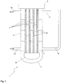
- FIG. 1 An inventive heat exchanger 1 is in FIG. 1 shown.
- the outer shell of the heat exchanger 1 is formed by the heat exchanger housing 5, the upward-closing heat exchanger hood 9 and the downwardly closing heat exchanger bottom 11.
- the heat exchanger tubes 3 are at least partially filled with water, which from a in FIG. 1 not shown connection is introduced.
- baffles 25 are installed in one embodiment so that a heat transfer medium 7 in meandering flow, the heat exchanger tubes 3 flows around.
- the liquid heat carrier 7 is supplied through a provided on the heat exchanger housing 5 inlet 13 in the lower half of the heat exchanger housing 5.
- the feed takes place approximately at the height of the heat exchanger tube bottom 31.
- the heat transfer medium 7 is largely transversely to the orientation of the heat exchanger tubes 3, that is carried out substantially horizontally on and between the heat exchanger tubes 3 and passed through the respective baffles 25.
- the cooled in its temperature heat transfer 7 is discharged again through a provided on the heat exchanger housing 5 drain 15 from the heat exchanger 1.
- the drain 15 is located in particular close to the heat exchanger hood 9. How the FIG. 1 can be seen, there is a Notentlastungsstutzen 17 also in the upper region of the heat exchanger housing 5 close to the heat exchanger hood 9.
- the emergency relief pipe 17 usually has a diameter between 100 mm and 800 mm.
- the safety device 19 according to the invention is arranged in the lower region of the heat exchanger housing 5, in particular in the lower third, preferably in the lower quarter, in particular in the lower fifth.
- the safety device 19 is in particular a Notentschreib, which is formed by a kind riser.
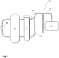
- FIG. 2 shows a reactor assembly 101 with a reactor 27, which is preferably a tube bundle reactor for performing exothermic or endothermic reactions.
- a reactor 27 which is preferably a tube bundle reactor for performing exothermic or endothermic reactions.
- a bundle of vertically aligned contact tubes is arranged between two tubesheets.
- the catalyst tubes can be filled with a bed of catalyst material (fixed bed catalyst).
- the catalyst tubes are surrounded by the liquid heat carrier 7, which absorbs and dissipates the heat generated during the exothermic reaction or which supplies the heat required in the endothermic reaction.
- the constant reaction conditions are created by circulating the heat carrier 7 at a predetermined temperature with a pump for temperature control.
- the heat transfer medium 7 enters the reactor 27 in the vicinity of the lower tube plate and leaves it in the vicinity of the upper tube plate.
- the reactor 27 is traversed by the heat carrier 7, which is circulated for circulation at least partially by at least one pump 29.
- the pump 29 and the corresponding supply and discharge lines of the pump 29 are accompanied by heating, so that no unwanted cooling and thus viscosity reduction of the heat carrier 7 occurs.
- the pump 29 is attached directly to the reactor housing.
- the heat exchanger 1 according to the invention is arranged substantially opposite to the pump 29.
- this is arranged at a relatively small distance, that is, with a distance of 10 cm to 250 cm from the reactor 27. From the heat exchanger 1 leads in the upper part, as in FIG. 1 already shown, the emergency relief 17 out.
- the safety device 19 essential to the invention is arranged in the lower region of the heat exchanger 1.
- the liquid heat carrier 7 can be separated from the water / steam mixture. This can be done in particular by means of a device for separating the liquid heat carrier 7 from a gaseous phase. The separation can be carried out by a cyclone separator or simply by gravity separation. The heat transfer medium 7 can then have an in FIG. 2 not shown line to the heat exchanger 1 and the reactor 27 are fed again.
Landscapes
- Engineering & Computer Science (AREA)
- Physics & Mathematics (AREA)
- Thermal Sciences (AREA)
- Mechanical Engineering (AREA)
- General Engineering & Computer Science (AREA)
- Chemical & Material Sciences (AREA)
- Organic Chemistry (AREA)
- Chemical Kinetics & Catalysis (AREA)
- Heat-Exchange Devices With Radiators And Conduit Assemblies (AREA)
- Structure Of Emergency Protection For Nuclear Reactors (AREA)
- Heat-Pump Type And Storage Water Heaters (AREA)
- Details Of Heat-Exchange And Heat-Transfer (AREA)
Claims (15)
- Échangeur de chaleur (1) comprenant- un faisceau d'au moins deux tubes d'échangeur de chaleur (3), le faisceau de tubes d'échangeur de chaleur (3) étant orienté verticalement et fermé vers le bas par un fond de tube d'échangeur de chaleur (31),- un boîtier d'échangeur de chaleur (5) entourant le faisceau de tubes d'échangeur de chaleur (3), le faisceau de tubes d'échangeur de chaleur (3) placé dans le boîtier d'échangeur de chaleur (5) étant entouré par un caloporteur liquide (7),- un capot d'échangeur de chaleur (9) fermant vers le haut le boîtier d'échangeur de chaleur (5),- un fond d'échangeur de chaleur (11) fermant vers le bas le boîtier d'échangeur de chaleur (5),- une entrée (15) prévue au niveau du boîtier d'échangeur de chaleur (5) et destinée à l'entrée du caloporteur (7) dans l'échangeur de chaleur (1),- une sortie (13) prévue au niveau du boîtier d'échangeur de chaleur (5) et destinée à la sortie du caloporteur (7) de l'échangeur de chaleur (1) et- une buse de décharge d'urgence (17), disposée à proximité du capot d'échangeur de chaleur (9),caractérisé en ce que
l'échangeur de chaleur (1) comporte un deuxième dispositif de sécurité (19) disposé à proximité du fond d'échangeur de chaleur (11), le deuxième dispositif de sécurité (19) étant une détente d'urgence. - Échangeur de chaleur (1) selon la revendication 1, le rapport de la section transversale libre du dispositif de sécurité (19) à la section transversale libre d'un tube d'échangeur de chaleur (3) étant compris entre 15 et 1600.
- Échangeur de chaleur (1) selon la revendication 1 ou 2, l'échangeur de chaleur (1) comportant un dispositif collecteur (21) destiné au caloporteur (7) et situé en aval du dispositif de sécurité (19) et/ou de la buse de décharge d'urgence (17).
- Échangeur de chaleur (1) selon l'une des revendications 1 à 3, l'échangeur de chaleur (1) comportant un dispositif de séparation du caloporteur liquide (7) d'une phase gazeuse.
- Échangeur de chaleur (1) selon l'une des revendications 1 à 4, l'échangeur de chaleur (1) comprenant entre le dispositif de sécurité (19) et le dispositif collecteur (21) un séparateur (23) destiné à une partie du caloporteur liquide (7).
- Échangeur de chaleur (1) selon l'une des revendications 1 à 5, l'échangeur de chaleur (1) comporte des éléments intégrés (25) destinés à dévier le caloporteur liquide (7) et les éléments intégrés (25) étant positionnés au niveau des tubes d'échangeur de chaleur individuels (3) ou entre ceux-ci et/ou au niveau des tubes d'échangeur de chaleur individuels (3) et du boîtier d'échangeur de chaleur (5) ou entre ceux-ci.
- Échangeur de chaleur (1) selon l'une des revendications 1 à 6, l'échangeur de chaleur (1) étant un échangeur de chaleur à bain de sel et/ou le caloporteur liquide (7) étant un sel fondu.
- Ensemble formant réacteur (101) comprenant- un réacteur (27)- un échangeur de chaleur (1), relié au réacteur (27), selon l'une des revendications 1 à 7,- une pompe (29) reliée au réacteur (27) et/ou à l'échangeur de chaleur (1) et destinée à faire circuler au moins une partie du caloporteur liquide (7).
- Ensemble formant réacteur (101) selon la revendication 8, le réacteur (27) étant un réacteur à faisceau de tubes destiné à réaliser des réactions exothermiques ou endothermiques.
- Procédé de régulation de température d'un réacteur (27), le procédé comprenant les étapes suivantes :a) introduire au moins une partie d'un caloporteur liquide (7), qui est déchargée du réacteur (27) à une première température T1, par une entrée dans l'échangeur de chaleur (1) selon l'une des revendications 1 à 7,b) rincer les tubes d'échangeur de chaleur (3) de l'échangeur de chaleur (1) avec le caloporteur liquide (7), de la chaleur étant échangée entre le caloporteur (7) et les tubes d'échangeur de chaleur (3),c) évacuer le caloporteur liquide (7) à une deuxième température T2 de l'échangeur de chaleur (1) et amener le caloporteur liquide (7) au réacteur (27),dans le cas d'une augmentation de pression dans l'échangeur de chaleur (1), la surpression résultante étant réduite au moins par l'intermédiaire d'un dispositif de sécurité (19).
- Procédé selon la revendication 10, le fluide caloporteur (7) serpentant à l'étape b) entre les tubes d'échangeur de chaleur (3).
- Procédé selon la revendication 10 ou 11, le réacteur (27) étant un réacteur à faisceau de tubes destiné à mettre en oeuvre des réactions exothermiques ou endothermiques.
- Procédé selon l'une des revendications 10 à 12, la réaction réalisée dans le réacteur (27) étant une oxydation partielle en phase gazeuse.
- Procédé selon la revendication 13, l'oxydation partielle en phase gazeuse comprenant l'oxydation du propène en acroléine, de l'isobutène en méthacroléine, de l'acroléine en acide acrylique, de la méthacroléine en acide méthacrylique et de l'o-xylène en anhydride phtalique.
- Utilisation de l'échangeur de chaleur (1) selon l'une des revendications 1 à 7 pour refroidir un réacteur (27) réalisant des réactions exothermiques, le réacteur (27) étant un réacteur à faisceau de tubes et le caloporteur liquide (7) étant un sel fondu.
Applications Claiming Priority (3)
| Application Number | Priority Date | Filing Date | Title |
|---|---|---|---|
| US201461954669P | 2014-03-18 | 2014-03-18 | |
| DE102014103691.3A DE102014103691A1 (de) | 2014-03-18 | 2014-03-18 | Wärmetauscher, Reaktoranordnung umfassend diesen Wärmetauscher und Verfahren zum Temperieren eines Reaktors |
| PCT/EP2015/054962 WO2015140009A2 (fr) | 2014-03-18 | 2015-03-10 | Échangeur de chaleur, système de réacteur comprenant cet échangeur de chaleur et procédé d'équilibrage thermique d'un réacteur |
Publications (2)
| Publication Number | Publication Date |
|---|---|
| EP3120099A2 EP3120099A2 (fr) | 2017-01-25 |
| EP3120099B1 true EP3120099B1 (fr) | 2019-06-12 |
Family
ID=54053408
Family Applications (1)
| Application Number | Title | Priority Date | Filing Date |
|---|---|---|---|
| EP15710466.2A Active EP3120099B1 (fr) | 2014-03-18 | 2015-03-10 | Échangeur de chaleur, système de réacteur comprenant cet échangeur de chaleur et procédé d'équilibrage thermique d'un réacteur |
Country Status (12)
| Country | Link |
|---|---|
| US (1) | US9797657B2 (fr) |
| EP (1) | EP3120099B1 (fr) |
| JP (1) | JP6429895B2 (fr) |
| KR (1) | KR102364341B1 (fr) |
| CN (1) | CN106104188B (fr) |
| BR (1) | BR112016021210B1 (fr) |
| DE (1) | DE102014103691A1 (fr) |
| MY (1) | MY182526A (fr) |
| RU (1) | RU2676167C2 (fr) |
| SG (1) | SG11201607209UA (fr) |
| TW (1) | TWI664387B (fr) |
| WO (1) | WO2015140009A2 (fr) |
Families Citing this family (5)
| Publication number | Priority date | Publication date | Assignee | Title |
|---|---|---|---|---|
| DE102014114193A1 (de) | 2014-09-30 | 2015-08-13 | Basf Se | Verfahren und Anlage zur Rückgewinnung von Acrylsäure |
| US20170356701A1 (en) * | 2016-06-13 | 2017-12-14 | Chevron U.S.A. Inc. | Apparatus, systems and methods for protection against high pressure gas intrusion in shell and tube heat exchangers |
| GEP20227358B (en) | 2017-10-27 | 2022-02-25 | Stamicarbon | High pressure carbamate condenser |
| EP3534100A1 (fr) * | 2018-02-28 | 2019-09-04 | Valeo Autosystemy SP. Z.O.O. | Échangeur de chaleur |
| CN117500585A (zh) | 2021-06-16 | 2024-02-02 | 巴斯夫欧洲公司 | 将催化气相反应的管式反应器关闭和加热的方法 |
Family Cites Families (15)
| Publication number | Priority date | Publication date | Assignee | Title |
|---|---|---|---|---|
| DE898917C (de) * | 1942-09-20 | 1953-12-07 | Aenne Maria Luise Moos | Allseitig geschlossener Solekuehler |
| DE1057623B (de) * | 1955-02-08 | 1959-05-21 | Foster Wheeler Ltd | Zum Waermeaustausch zwischen einer Fluessigkeit und einem anderen Medium dienender Waermeaustauscher |
| BE795180A (fr) | 1972-02-16 | 1973-05-29 | Deggendorfer Werft Eisenbau | Groupe refroidisseur destine a des appareils pour la realisation de reactions chimiques exothermiques |
| US4511432A (en) * | 1982-09-07 | 1985-04-16 | Sephton Hugo H | Feed distribution method for vertical tube evaporation |
| ZA200004211B (en) * | 1999-08-31 | 2001-02-14 | Nippon Catalytic Chem Ind | Method for catalytic gas phase oxidation. |
| DE102004041777A1 (de) * | 2004-08-28 | 2006-03-02 | Bayer Materialscience Ag | Verfahren und Vorrichtung zur Herstellung von Phosgen |
| WO2007048603A2 (fr) * | 2005-10-26 | 2007-05-03 | Behr Gmbh & Co. Kg | Echangeur de chaleur et procede de fabrication d'un echangeur de chaleur |
| DE102006034811A1 (de) * | 2006-07-27 | 2008-01-31 | Man Dwe Gmbh | Verfahren zur Temperaturänderung eines Rohrbündelreaktors |
| CN101977677B (zh) * | 2008-01-25 | 2015-02-18 | 巴斯夫欧洲公司 | 进行高压反应的反应器,启动的方法和进行反应的方法 |
| DE102008048405B3 (de) * | 2008-09-23 | 2010-04-22 | Alstom Technology Ltd. | Rohrbündel-Wärmetauscher zur Regelung eines breiten Leistungsbereiches |
| CN201444004U (zh) * | 2009-06-22 | 2010-04-28 | 大连优力特换热设备制造有限公司 | 一种可拆卸板式换热器 |
| JP2012149871A (ja) * | 2010-12-28 | 2012-08-09 | Sumitomo Chemical Co Ltd | 多管式熱交換構造 |
| CN102455139B (zh) * | 2011-10-18 | 2014-04-16 | 张周卫 | 一种带真空绝热的双股流低温螺旋缠绕管式换热器 |
| RU134687U1 (ru) * | 2013-04-08 | 2013-11-20 | Федеральное государственное бюджетное образовательное учреждение высшего профессионального образования "Санкт-Петербургский государственный морской технический университет" | Система пассивного отвода тепла реакторной установки |
| CN203349689U (zh) * | 2013-05-16 | 2013-12-18 | 江苏昊隆换热器有限公司 | 一种新型板式换热器 |
-
2014
- 2014-03-18 DE DE102014103691.3A patent/DE102014103691A1/de not_active Withdrawn
-
2015
- 2015-03-10 MY MYPI2016001659A patent/MY182526A/en unknown
- 2015-03-10 EP EP15710466.2A patent/EP3120099B1/fr active Active
- 2015-03-10 JP JP2016558126A patent/JP6429895B2/ja active Active
- 2015-03-10 BR BR112016021210-0A patent/BR112016021210B1/pt active IP Right Grant
- 2015-03-10 SG SG11201607209UA patent/SG11201607209UA/en unknown
- 2015-03-10 WO PCT/EP2015/054962 patent/WO2015140009A2/fr active Application Filing
- 2015-03-10 RU RU2016140695A patent/RU2676167C2/ru active
- 2015-03-10 CN CN201580014566.2A patent/CN106104188B/zh active Active
- 2015-03-10 KR KR1020167028745A patent/KR102364341B1/ko active IP Right Grant
- 2015-03-18 TW TW104108662A patent/TWI664387B/zh active
- 2015-03-18 US US14/661,408 patent/US9797657B2/en active Active
Non-Patent Citations (1)
| Title |
|---|
| None * |
Also Published As
| Publication number | Publication date |
|---|---|
| CN106104188B (zh) | 2018-10-09 |
| RU2676167C2 (ru) | 2018-12-26 |
| CN106104188A (zh) | 2016-11-09 |
| KR102364341B1 (ko) | 2022-02-17 |
| KR20160133544A (ko) | 2016-11-22 |
| JP2017510783A (ja) | 2017-04-13 |
| WO2015140009A3 (fr) | 2016-03-10 |
| DE102014103691A1 (de) | 2015-09-24 |
| JP6429895B2 (ja) | 2018-11-28 |
| TWI664387B (zh) | 2019-07-01 |
| RU2016140695A (ru) | 2018-04-18 |
| SG11201607209UA (en) | 2016-10-28 |
| EP3120099A2 (fr) | 2017-01-25 |
| MY182526A (en) | 2021-01-25 |
| BR112016021210B1 (pt) | 2020-12-29 |
| TW201544784A (zh) | 2015-12-01 |
| WO2015140009A2 (fr) | 2015-09-24 |
| US20150267967A1 (en) | 2015-09-24 |
| RU2016140695A3 (fr) | 2018-10-24 |
| US9797657B2 (en) | 2017-10-24 |
Similar Documents
| Publication | Publication Date | Title |
|---|---|---|
| EP3120099B1 (fr) | Échangeur de chaleur, système de réacteur comprenant cet échangeur de chaleur et procédé d'équilibrage thermique d'un réacteur | |
| EP1882518B1 (fr) | Procédé de modification de la température d'un réacteur à faisceau tubulaire | |
| DE3414717A1 (de) | Verfahren und reaktor zur durchfuehrung exothermer katalytischer reaktionen | |
| DE1941005A1 (de) | Dampferzeuger,insbesondere fuer einen Betrieb mit fluessigem Metall oder geschmolzenen Salzen als Heizmedium | |
| DE2400882A1 (de) | Mantel- und rohrwaermeaustauscher | |
| DE2432131A1 (de) | Notkuehleinrichtung fuer einen kernreaktor | |
| DE2109825B2 (de) | Dampferzeuger mit in einem vertikalen Druckbehälter angeordneten Rohrbündel | |
| WO2014009346A1 (fr) | Dispositif et procédé de préparation du phosgène | |
| DE1929474B2 (de) | Wärmeaustauscher fur heiße stro mende Gase | |
| EP3032209B1 (fr) | Systeme de refroidisseur a injection | |
| EP3536763A1 (fr) | Système de refroidissement | |
| DE1927949A1 (de) | Dampferzeugungs- und -ueberhitzungsvorrichtung,insbesondere fuer mit geschmolzenem Metall,geschmolzenem Metallsalz od.dgl. als Waermeuebertrager arbeitende Kernreaktoren | |
| EP1060475A1 (fr) | Enceinte de confinement et procede pour actionner un condenseur dans une centrale nucleaire | |
| DE1576867B2 (de) | Im Kuhlmittelstrom eines Kernreaktors angeordneter Dampferzeuger | |
| DE2851197A1 (de) | Fluessigmetall-beheizter dampferzeuger mit integrierter zwischenueberhitzung | |
| DE2621258A1 (de) | Kernenergieanlage mit verbesserten einrichtungen zur nach- und notwaermeabfuhr | |
| EP3984046B1 (fr) | Système de refroidissement de cuve de réacteur sous pression | |
| DE2249811A1 (de) | Waermeaustauscher | |
| WO2015140008A1 (fr) | Système de réacteur et utilisation dudit système | |
| WO2016005132A1 (fr) | Système et procédé pour faire fonctionner un évaporateur de gaz liquéfié | |
| CH628131A5 (de) | Dampferzeuger mit einem druckkessel und einem rohrbuendel. | |
| DE102021002515B3 (de) | Sicherheitsbehälterkühlsystem | |
| DE2824667C2 (de) | Dampfbeheizter Wärmeübertrager, insbesondere für kondensatseitige Regelung der Wärmeübertragung | |
| DE1576867C (de) | Im Kühlmittelstrom eines Kernreaktors angeordneter Dampferzeuger | |
| DE102011005481A1 (de) | Wärmetauscher |
Legal Events
| Date | Code | Title | Description |
|---|---|---|---|
| STAA | Information on the status of an ep patent application or granted ep patent |
Free format text: STATUS: THE INTERNATIONAL PUBLICATION HAS BEEN MADE |
|
| PUAI | Public reference made under article 153(3) epc to a published international application that has entered the european phase |
Free format text: ORIGINAL CODE: 0009012 |
|
| STAA | Information on the status of an ep patent application or granted ep patent |
Free format text: STATUS: REQUEST FOR EXAMINATION WAS MADE |
|
| 17P | Request for examination filed |
Effective date: 20161018 |
|
| AK | Designated contracting states |
Kind code of ref document: A2 Designated state(s): AL AT BE BG CH CY CZ DE DK EE ES FI FR GB GR HR HU IE IS IT LI LT LU LV MC MK MT NL NO PL PT RO RS SE SI SK SM TR |
|
| AX | Request for extension of the european patent |
Extension state: BA ME |
|
| DAV | Request for validation of the european patent (deleted) | ||
| DAX | Request for extension of the european patent (deleted) | ||
| STAA | Information on the status of an ep patent application or granted ep patent |
Free format text: STATUS: EXAMINATION IS IN PROGRESS |
|
| 17Q | First examination report despatched |
Effective date: 20180104 |
|
| GRAP | Despatch of communication of intention to grant a patent |
Free format text: ORIGINAL CODE: EPIDOSNIGR1 |
|
| STAA | Information on the status of an ep patent application or granted ep patent |
Free format text: STATUS: GRANT OF PATENT IS INTENDED |
|
| INTG | Intention to grant announced |
Effective date: 20190104 |
|
| GRAS | Grant fee paid |
Free format text: ORIGINAL CODE: EPIDOSNIGR3 |
|
| GRAA | (expected) grant |
Free format text: ORIGINAL CODE: 0009210 |
|
| STAA | Information on the status of an ep patent application or granted ep patent |
Free format text: STATUS: THE PATENT HAS BEEN GRANTED |
|
| AK | Designated contracting states |
Kind code of ref document: B1 Designated state(s): AL AT BE BG CH CY CZ DE DK EE ES FI FR GB GR HR HU IE IS IT LI LT LU LV MC MK MT NL NO PL PT RO RS SE SI SK SM TR |
|
| REG | Reference to a national code |
Ref country code: GB Ref legal event code: FG4D Free format text: NOT ENGLISH |
|
| REG | Reference to a national code |
Ref country code: CH Ref legal event code: EP |
|
| REG | Reference to a national code |
Ref country code: AT Ref legal event code: REF Ref document number: 1143112 Country of ref document: AT Kind code of ref document: T Effective date: 20190615 |
|
| REG | Reference to a national code |
Ref country code: DE Ref legal event code: R096 Ref document number: 502015009307 Country of ref document: DE |
|
| REG | Reference to a national code |
Ref country code: IE Ref legal event code: FG4D Free format text: LANGUAGE OF EP DOCUMENT: GERMAN |
|
| REG | Reference to a national code |
Ref country code: NL Ref legal event code: MP Effective date: 20190612 |
|
| REG | Reference to a national code |
Ref country code: LT Ref legal event code: MG4D |
|
| PG25 | Lapsed in a contracting state [announced via postgrant information from national office to epo] |
Ref country code: HR Free format text: LAPSE BECAUSE OF FAILURE TO SUBMIT A TRANSLATION OF THE DESCRIPTION OR TO PAY THE FEE WITHIN THE PRESCRIBED TIME-LIMIT Effective date: 20190612 Ref country code: NO Free format text: LAPSE BECAUSE OF FAILURE TO SUBMIT A TRANSLATION OF THE DESCRIPTION OR TO PAY THE FEE WITHIN THE PRESCRIBED TIME-LIMIT Effective date: 20190912 Ref country code: SE Free format text: LAPSE BECAUSE OF FAILURE TO SUBMIT A TRANSLATION OF THE DESCRIPTION OR TO PAY THE FEE WITHIN THE PRESCRIBED TIME-LIMIT Effective date: 20190612 Ref country code: FI Free format text: LAPSE BECAUSE OF FAILURE TO SUBMIT A TRANSLATION OF THE DESCRIPTION OR TO PAY THE FEE WITHIN THE PRESCRIBED TIME-LIMIT Effective date: 20190612 Ref country code: AL Free format text: LAPSE BECAUSE OF FAILURE TO SUBMIT A TRANSLATION OF THE DESCRIPTION OR TO PAY THE FEE WITHIN THE PRESCRIBED TIME-LIMIT Effective date: 20190612 Ref country code: LT Free format text: LAPSE BECAUSE OF FAILURE TO SUBMIT A TRANSLATION OF THE DESCRIPTION OR TO PAY THE FEE WITHIN THE PRESCRIBED TIME-LIMIT Effective date: 20190612 |
|
| PG25 | Lapsed in a contracting state [announced via postgrant information from national office to epo] |
Ref country code: BG Free format text: LAPSE BECAUSE OF FAILURE TO SUBMIT A TRANSLATION OF THE DESCRIPTION OR TO PAY THE FEE WITHIN THE PRESCRIBED TIME-LIMIT Effective date: 20190912 Ref country code: RS Free format text: LAPSE BECAUSE OF FAILURE TO SUBMIT A TRANSLATION OF THE DESCRIPTION OR TO PAY THE FEE WITHIN THE PRESCRIBED TIME-LIMIT Effective date: 20190612 Ref country code: GR Free format text: LAPSE BECAUSE OF FAILURE TO SUBMIT A TRANSLATION OF THE DESCRIPTION OR TO PAY THE FEE WITHIN THE PRESCRIBED TIME-LIMIT Effective date: 20190913 Ref country code: LV Free format text: LAPSE BECAUSE OF FAILURE TO SUBMIT A TRANSLATION OF THE DESCRIPTION OR TO PAY THE FEE WITHIN THE PRESCRIBED TIME-LIMIT Effective date: 20190612 |
|
| PG25 | Lapsed in a contracting state [announced via postgrant information from national office to epo] |
Ref country code: NL Free format text: LAPSE BECAUSE OF FAILURE TO SUBMIT A TRANSLATION OF THE DESCRIPTION OR TO PAY THE FEE WITHIN THE PRESCRIBED TIME-LIMIT Effective date: 20190612 Ref country code: CZ Free format text: LAPSE BECAUSE OF FAILURE TO SUBMIT A TRANSLATION OF THE DESCRIPTION OR TO PAY THE FEE WITHIN THE PRESCRIBED TIME-LIMIT Effective date: 20190612 Ref country code: RO Free format text: LAPSE BECAUSE OF FAILURE TO SUBMIT A TRANSLATION OF THE DESCRIPTION OR TO PAY THE FEE WITHIN THE PRESCRIBED TIME-LIMIT Effective date: 20190612 Ref country code: EE Free format text: LAPSE BECAUSE OF FAILURE TO SUBMIT A TRANSLATION OF THE DESCRIPTION OR TO PAY THE FEE WITHIN THE PRESCRIBED TIME-LIMIT Effective date: 20190612 Ref country code: PT Free format text: LAPSE BECAUSE OF FAILURE TO SUBMIT A TRANSLATION OF THE DESCRIPTION OR TO PAY THE FEE WITHIN THE PRESCRIBED TIME-LIMIT Effective date: 20191014 Ref country code: SK Free format text: LAPSE BECAUSE OF FAILURE TO SUBMIT A TRANSLATION OF THE DESCRIPTION OR TO PAY THE FEE WITHIN THE PRESCRIBED TIME-LIMIT Effective date: 20190612 |
|
| PG25 | Lapsed in a contracting state [announced via postgrant information from national office to epo] |
Ref country code: SM Free format text: LAPSE BECAUSE OF FAILURE TO SUBMIT A TRANSLATION OF THE DESCRIPTION OR TO PAY THE FEE WITHIN THE PRESCRIBED TIME-LIMIT Effective date: 20190612 Ref country code: IT Free format text: LAPSE BECAUSE OF FAILURE TO SUBMIT A TRANSLATION OF THE DESCRIPTION OR TO PAY THE FEE WITHIN THE PRESCRIBED TIME-LIMIT Effective date: 20190612 Ref country code: IS Free format text: LAPSE BECAUSE OF FAILURE TO SUBMIT A TRANSLATION OF THE DESCRIPTION OR TO PAY THE FEE WITHIN THE PRESCRIBED TIME-LIMIT Effective date: 20191012 Ref country code: ES Free format text: LAPSE BECAUSE OF FAILURE TO SUBMIT A TRANSLATION OF THE DESCRIPTION OR TO PAY THE FEE WITHIN THE PRESCRIBED TIME-LIMIT Effective date: 20190612 |
|
| REG | Reference to a national code |
Ref country code: DE Ref legal event code: R097 Ref document number: 502015009307 Country of ref document: DE |
|
| PG25 | Lapsed in a contracting state [announced via postgrant information from national office to epo] |
Ref country code: TR Free format text: LAPSE BECAUSE OF FAILURE TO SUBMIT A TRANSLATION OF THE DESCRIPTION OR TO PAY THE FEE WITHIN THE PRESCRIBED TIME-LIMIT Effective date: 20190612 |
|
| PLBE | No opposition filed within time limit |
Free format text: ORIGINAL CODE: 0009261 |
|
| STAA | Information on the status of an ep patent application or granted ep patent |
Free format text: STATUS: NO OPPOSITION FILED WITHIN TIME LIMIT |
|
| PG25 | Lapsed in a contracting state [announced via postgrant information from national office to epo] |
Ref country code: PL Free format text: LAPSE BECAUSE OF FAILURE TO SUBMIT A TRANSLATION OF THE DESCRIPTION OR TO PAY THE FEE WITHIN THE PRESCRIBED TIME-LIMIT Effective date: 20190612 Ref country code: DK Free format text: LAPSE BECAUSE OF FAILURE TO SUBMIT A TRANSLATION OF THE DESCRIPTION OR TO PAY THE FEE WITHIN THE PRESCRIBED TIME-LIMIT Effective date: 20190612 |
|
| 26N | No opposition filed |
Effective date: 20200313 |
|
| PG25 | Lapsed in a contracting state [announced via postgrant information from national office to epo] |
Ref country code: IS Free format text: LAPSE BECAUSE OF FAILURE TO SUBMIT A TRANSLATION OF THE DESCRIPTION OR TO PAY THE FEE WITHIN THE PRESCRIBED TIME-LIMIT Effective date: 20200224 Ref country code: SI Free format text: LAPSE BECAUSE OF FAILURE TO SUBMIT A TRANSLATION OF THE DESCRIPTION OR TO PAY THE FEE WITHIN THE PRESCRIBED TIME-LIMIT Effective date: 20190612 |
|
| PG2D | Information on lapse in contracting state deleted |
Ref country code: IS |
|
| PG25 | Lapsed in a contracting state [announced via postgrant information from national office to epo] |
Ref country code: MC Free format text: LAPSE BECAUSE OF FAILURE TO SUBMIT A TRANSLATION OF THE DESCRIPTION OR TO PAY THE FEE WITHIN THE PRESCRIBED TIME-LIMIT Effective date: 20190612 |
|
| REG | Reference to a national code |
Ref country code: CH Ref legal event code: PL |
|
| PG25 | Lapsed in a contracting state [announced via postgrant information from national office to epo] |
Ref country code: LU Free format text: LAPSE BECAUSE OF NON-PAYMENT OF DUE FEES Effective date: 20200310 |
|
| PG25 | Lapsed in a contracting state [announced via postgrant information from national office to epo] |
Ref country code: FR Free format text: LAPSE BECAUSE OF NON-PAYMENT OF DUE FEES Effective date: 20200331 Ref country code: CH Free format text: LAPSE BECAUSE OF NON-PAYMENT OF DUE FEES Effective date: 20200331 Ref country code: IE Free format text: LAPSE BECAUSE OF NON-PAYMENT OF DUE FEES Effective date: 20200310 Ref country code: LI Free format text: LAPSE BECAUSE OF NON-PAYMENT OF DUE FEES Effective date: 20200331 |
|
| GBPC | Gb: european patent ceased through non-payment of renewal fee |
Effective date: 20200310 |
|
| PG25 | Lapsed in a contracting state [announced via postgrant information from national office to epo] |
Ref country code: GB Free format text: LAPSE BECAUSE OF NON-PAYMENT OF DUE FEES Effective date: 20200310 |
|
| REG | Reference to a national code |
Ref country code: AT Ref legal event code: MM01 Ref document number: 1143112 Country of ref document: AT Kind code of ref document: T Effective date: 20200310 |
|
| PG25 | Lapsed in a contracting state [announced via postgrant information from national office to epo] |
Ref country code: AT Free format text: LAPSE BECAUSE OF NON-PAYMENT OF DUE FEES Effective date: 20200310 |
|
| PG25 | Lapsed in a contracting state [announced via postgrant information from national office to epo] |
Ref country code: MT Free format text: LAPSE BECAUSE OF FAILURE TO SUBMIT A TRANSLATION OF THE DESCRIPTION OR TO PAY THE FEE WITHIN THE PRESCRIBED TIME-LIMIT Effective date: 20190612 Ref country code: CY Free format text: LAPSE BECAUSE OF FAILURE TO SUBMIT A TRANSLATION OF THE DESCRIPTION OR TO PAY THE FEE WITHIN THE PRESCRIBED TIME-LIMIT Effective date: 20190612 |
|
| PG25 | Lapsed in a contracting state [announced via postgrant information from national office to epo] |
Ref country code: MK Free format text: LAPSE BECAUSE OF FAILURE TO SUBMIT A TRANSLATION OF THE DESCRIPTION OR TO PAY THE FEE WITHIN THE PRESCRIBED TIME-LIMIT Effective date: 20190612 |
|
| PGFP | Annual fee paid to national office [announced via postgrant information from national office to epo] |
Ref country code: BE Payment date: 20230323 Year of fee payment: 9 |
|
| PGFP | Annual fee paid to national office [announced via postgrant information from national office to epo] |
Ref country code: DE Payment date: 20240328 Year of fee payment: 10 |