EP3120048B1 - Gear shifter including a position sensor assembly - Google Patents
Gear shifter including a position sensor assembly Download PDFInfo
- Publication number
- EP3120048B1 EP3120048B1 EP14710899.7A EP14710899A EP3120048B1 EP 3120048 B1 EP3120048 B1 EP 3120048B1 EP 14710899 A EP14710899 A EP 14710899A EP 3120048 B1 EP3120048 B1 EP 3120048B1
- Authority
- EP
- European Patent Office
- Prior art keywords
- shift lever
- axis
- element carrier
- path
- position sensors
- Prior art date
- Legal status (The legal status is an assumption and is not a legal conclusion. Google has not performed a legal analysis and makes no representation as to the accuracy of the status listed.)
- Active
Links
Images


Classifications
-
- F—MECHANICAL ENGINEERING; LIGHTING; HEATING; WEAPONS; BLASTING
- F16—ENGINEERING ELEMENTS AND UNITS; GENERAL MEASURES FOR PRODUCING AND MAINTAINING EFFECTIVE FUNCTIONING OF MACHINES OR INSTALLATIONS; THERMAL INSULATION IN GENERAL
- F16H—GEARING
- F16H59/00—Control inputs to control units of change-speed-, or reversing-gearings for conveying rotary motion
- F16H59/02—Selector apparatus
- F16H59/08—Range selector apparatus
- F16H59/10—Range selector apparatus comprising levers
- F16H59/105—Range selector apparatus comprising levers consisting of electrical switches or sensors
-
- F—MECHANICAL ENGINEERING; LIGHTING; HEATING; WEAPONS; BLASTING
- F16—ENGINEERING ELEMENTS AND UNITS; GENERAL MEASURES FOR PRODUCING AND MAINTAINING EFFECTIVE FUNCTIONING OF MACHINES OR INSTALLATIONS; THERMAL INSULATION IN GENERAL
- F16H—GEARING
- F16H59/00—Control inputs to control units of change-speed-, or reversing-gearings for conveying rotary motion
- F16H59/02—Selector apparatus
- F16H59/0204—Selector apparatus for automatic transmissions with means for range selection and manual shifting, e.g. range selector with tiptronic
-
- F—MECHANICAL ENGINEERING; LIGHTING; HEATING; WEAPONS; BLASTING
- F16—ENGINEERING ELEMENTS AND UNITS; GENERAL MEASURES FOR PRODUCING AND MAINTAINING EFFECTIVE FUNCTIONING OF MACHINES OR INSTALLATIONS; THERMAL INSULATION IN GENERAL
- F16H—GEARING
- F16H59/00—Control inputs to control units of change-speed-, or reversing-gearings for conveying rotary motion
- F16H59/02—Selector apparatus
- F16H59/04—Ratio selector apparatus
- F16H59/044—Ratio selector apparatus consisting of electrical switches or sensors
-
- F—MECHANICAL ENGINEERING; LIGHTING; HEATING; WEAPONS; BLASTING
- F16—ENGINEERING ELEMENTS AND UNITS; GENERAL MEASURES FOR PRODUCING AND MAINTAINING EFFECTIVE FUNCTIONING OF MACHINES OR INSTALLATIONS; THERMAL INSULATION IN GENERAL
- F16H—GEARING
- F16H59/00—Control inputs to control units of change-speed-, or reversing-gearings for conveying rotary motion
- F16H59/02—Selector apparatus
- F16H2059/026—Details or special features of the selector casing or lever support
- F16H2059/0269—Ball joints or spherical bearings for supporting the lever
Definitions
- the present invention is directed to a gear shifter for a transmission of a vehicle comprising a shift lever which is mounted in a housing to be pivotable about a first axis, a position sensor assembly disposed stationary in the housing and comprising a plurality of position sensors distributed along a path, a sensor triggering element mounted on an element carrier which is moveably mounted in the housing and coupled to the shift lever by a linkage in such a manner to be able to move the sensor triggering element along said path of position sensors in response to pivotal shift movements of the shift lever about the first axis.
- Such gear shifters are for example utilized in shift-by-wire gear shifter assemblies or in Tip-Tronic shifters (including mechanical PRND and an electrical manual shifting mode) in which the positioning of the shift lever is detected by a position sensor assembly, and a corresponding control signal is transmitted to the transmission for actuating it in the desired manner.
- a sensor triggering element e.g. a magnet
- a particular position sensor is activated when the sensor triggering element is positioned in close proximity to the particular position sensor.
- a gear shifter is disclosed in US 7, 614, 319 B2 .
- a shift lever is mounted in a housing to be pivotable about a first axis.
- the shift lever disclosed is indeed also pivotable about a second axis perpendicular to the first axis.
- a position sensor assembly is disposed stationary in the housing and comprises a plurality of position sensors distributed along a path.
- a sensor triggering element is mounted on an element carrier which is connected to the shift lever such that it follows the pivotable shift movements of the shift lever about the first axis. This movement of the element carrier is accompanied by moving the sensor triggering element along the path of position sensors.
- the position sensor that is in close proximity to the sensor triggering element signals the presence of the sensor triggering element and thus gives an indication of the positioning of the shift lever.
- the element carrier is connected to the shift lever at a position spaced apart from the pivotal mounting of the shift lever.
- the element carrier presses the sensor triggering element against a console wall on which the paths of position sensors is mounted.
- the sensor triggering element slides along the console wall with its position sensor path. The distances the sensor triggering element travels during pivotal shift movements of the shift lever depends only on the vertical distance of the sensor triggering element from the pivotal bearing of the shift lever in the housing.
- US 6,530,293 B1 describes a shift mechanism for vehicle transmissions with a selector lever pivotable about an axis.
- a component that is fixed to the selector lever and moves with the selector lever has a projecting element that is engaged by a fork-shaped receptacle of a support component carrying a permanent magnet for determining the position of the shift mechanism. Rotation of the selector lever about the first axis is transmitted to the support component by the engagement between the projecting element and the receptacle.
- JP 2008 239057 A discloses a gear shifter according to the preamble of claim 1.
- a link mechanism has a pair of links corresponding to the select direction and the shift direction. Magnets are attached to tips of the links.
- a receptacle for the end of a pivoting select lever is provided in the links to convert the movement of the select lever operated and turned in a vertical plane into a movement of the magnets in a horizontal plane relative to corresponding sensor components.
- JP S61 36751 U discloses a select lever pivotable about a pivot point.
- a spherical end of the select lever is received spaced from the pivot point in a receptacle of a carrier with a position sensor that moves relative to corresponding sensor components to indicate the position of the shift mechanism.
- the carrier is adapted to rotate about a rotational axis and to displace along the same.
- gear shifter comprising the features of claim 1.
- Preferred embodiments of the invention are set out in the depended claims.
- the element carrier is pivotally mounted in the housing with respect to the position sensor assembly at a pivot point which is spaced apart from the path of position sensors and the sensor triggering element such that a pivotal movement of the element carrier moves the sensor triggering element along the path of position sensors.
- the linkage is coupled to the element carrier at a location on the element carrier between its pivotal mounting and the sensor triggering element. Due to this arrangement the sensor triggering element is further away from the pivot point of the element carrier than the coupling of the linkage. Therefore, movements of the linkage in response to pivotal shift movements of the shift lever are transmitted into sensor triggering element movements over a longer distance because the sensor triggering element is disposed further away from the pivot axis of the element carrier than the coupling of the linkage to the element carrier.
- the pivotal shift movements of the shift lever are transmitted into sensor triggering element movements with a transmission ratio > 1. Since the sensor triggering element travels over a longer distance between shift positions of the shift lever the position sensors can be disposed along the path with greater distances in between. When the sensor triggering element is in proximity to one of the position sensors so that the position sensor senses its presence, the next position sensors along the path are sufficiently spaced apart so that an accidental triggering of one of the adjacent position sensors is excluded.
- the pivot axis of the pivotal mounting of the element carrier is parallel to the first axis, i.e. the element carrier pivots in a plane parallel to the plane in which the shift lever pivots during shift movements of the shift lever.
- the linkage transmitting shift lever movements to the element carrier comprises a link lever which is coupled at one of its ends to a lower end portion of the shift lever below the pivotal bearing of the shift lever in the housing, and which is rotably coupled at its other end to the element carrier.
- the shift lever is mounted in the housing to be pivotable about a second axis perpendicular to the first axis. This second axis allows to select a particular shift gate.
- the shift lever is pivotable about the second axis and the link lever is rotatably coupled to the shift lever to be pivotable about an axis parallel to the second axis.
- the link lever is coupled to the element carrier by a ball joint so that it can accommodate shift movements of the shift lever as well as select movements of the shift lever between different shift gates, whereas the element carrier is limited in its movements to a plane.
- the pivotal mounting of the element carrier comprises a pivot pin stationary with respect to the housing, and the element carrier is provided with an elongated slot for receiving the pivot pin such that the element carrier may be displaced with respect to the pivot pin which may slide along the elongated slot, when the shift lever is pivoted about the second axis.
- the position sensor assembly comprises a second path of position sensors disposed parallel to but displaced with respect to the first path such that the sensor triggering element on the element carrier may be brought from a positioning in alignment with the first path to a positioning in alignment with the second path of position sensors by pivoting the shift lever about the second axis in a first direction, and vice versa by pivoting the shift lever back in the opposite direction.
- the sensor triggering element comprises a magnet
- the position sensors comprise Hall sensors.
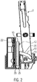
- the embodiment of the gear shifter according to the present invention shown in Figs. 1 to 9 comprises a shift lever 2 mounted in a housing (not shown), wherein the pivotal bearings of the shift lever 2 in the housing have been omitted to simplify the drawings.
- the shift lever 2 may be pivoted about a first axis, which first axis is perpendicular to the Figure plane of Figs. 6 to 9 so that during pivotal shift movements the shift lever 2 moves within the Figure plane of Figs. 6 to 9 .
- the shift lever 2 is further pivotable about a second axis, which second axis is perpendicular to the Figure plane of Figs. 2 to 5 , to move the shift lever from a first to a second shift gate and vice versa.
- the pivotal bearings of the shift lever 2 in the housing are proximately in the middle of the shift lever 2 shown in the Figures.
- a linkage 18 in the form of a U-shaped bracket is coupled to a lower end portion of the shift lever 2.
- the outer ends of the linkage legs 19 of the U-shaped bracket are each coupled to the shift lever 2 by a respective pin which is received in a coupling recess in the shift lever 2 such that the linkage 18 may pivot about the pins coupling the outer ends of its linkage legs 19 to the shift lever.
- the linkage apex 20 in the middle between the two outer ends of the linkage legs 19 is coupled to an element carrier 10 by a ball joint (not shown).
- the element carrier 10 is disposed in front of a wall 28 of an inner housing structure 22 and is moveable with respect to the wall surface.
- a pivot pin 12 is connected to the wall of the inner housing structure and is received within an elongated slot 11 (see Figs. 6 to 9 ) of element carrier 10. In this manner the element carrier 10 may pivot about pivot pin 12, and be moved up and down, wherein the positioning of the element carrier 10 is determined by the positioning of the linkage apex 20 of the linkage 18 which is coupled to the element carrier 10 by a ball joint (not shown).
- element carrier 10 is received and guided with its lower portion in a recess formed by the wall 28 of the inner housing structure 22 and a further wall 29 of the housing structure. In this recess the element carrier 10 can move vertically up and down (see Figs. 2 and 3 ), and may pivot about the pivot pin 12.
- the element carrier 10 carries in a lower end portion thereof a sensor triggering element 8, for example a magnet.
- a position sensor assembly 4 On the inner wall of the inner housing structure 22 against which the element carrier 10 is moved a position sensor assembly 4 (see Figs. 6 to 9 ) is disposed.
- This position sensor assembly 4 comprises three position sensors 6 distributed along a first path. In the illustrated embodiment there is a second path of position sensors disposed above the first path of position sensors 6.
- Each position sensor may for example include a hall sensor which is triggered by the sensor triggering element 8 when it comes into close proximity of one of the position sensors. In the position illustrated in Fig. 6 the first position sensor 6 on the right hand side would be triggered by the sensor triggering element 8, whereas all the remaining position sensors would be left inactivated.
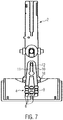
- a shift movement of the shift lever 2 is illustrated in Figs. 6 and 7 , wherein the shift movement of the shift lever 2 is transmitted by linkage 18 to the element carrier 10 such that it pivots about pivot pin 12.
- This pivotal movement of the element carrier 10 results in a corresponding pivotal movement of the sensor triggering element 8 carried at the lower end of the element carrier 10.
- the sensor triggering element 8 reached the central position sensor 6 in the path of position sensors 6.
- the shift movement of Figs. 6 and 7 is shown in a front view. In this view the lower end portion of the shift lever 2 is moved approximately perpendicular to the Figure plane during a shift movement.
- This pivotal movement of the shift lever 2 is accompanied by a slight pivotal movement of linkage 18 such that the linkage apex 20 is slightly pivoted downwards.
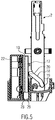
- Figs. 3 and 4 illustrate a shift movement of the shift lever 2 about the second axis, wherein this pivot movement of the shift lever 2 is in the Figure plane of Figs. 3 and 4 .
- This movement of the shift lever 2 corresponds to the movement between two shift gates.
- the lower end portion of the shift lever 2 is moved closer to the element carrier 10.
- the linkage apex 20 of linkage 18 is pivoted upwards.
- This pivoting of the linkage apex 20 upwards moves element carrier 10 in sliding contact against the wall 28 of the inner housing 22 vertically upwards.
- a corresponding movement can be seen in side view in Figs. 7 and 8 .
- Figs. 7 and 8 As can be seen from Figs.
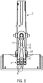
- the pivotal movement of the shift lever from Fig. 3 to Fig. 4 has the effect that the element carrier 10 is vertically lifted such that the sensor triggering element 8 carried at its lower end is moved from the central position sensor of the first path of position sensors ( Fig. 7 ) to the central position sensor of the second path of position sensors disposed above the first path of position sensors 6 ( Fig. 8 ).
- the element carrier 10 slides upwards with respect to the stationary pivot pin 12 which is accompanied by a relative movement of the pivot pin 12 within the elongated slot 11 of the element carrier 10.
- Figs. 8 and 9 illustrate a further shift movement of the shift lever 2 from a vertical upright positioning of the shift lever 2 ( Fig. 8 ) to a pivoted position of the shift lever 2 ( Fig. 8 ). Again, this shift movement of the shift lever is transmitted by the linkage 18 to the element carrier 10 such that it performs a pivotal movement about pivot pin 12 which moves the sensor triggering element 8 at its lower end from the central position sensor to the position sensor on the right hand side of the second path of opposition sensors.
- the front views corresponding to Figs. 8 and 9 are shown in Figs. 4 and 5 .
- the position sensors 6 may be placed at a greater distance to each other along the path of position sensors as compared to a transmission to the sensor triggering element with transmission ratio of 1 or smaller.
- the positioning of the position sensors 6 at a greater distance along the path of position sensors 6 permits a more reliable performance of the position sensor assembly since the risk that an adjacent position sensor is erroneously activated because it is too close to an adjacent position sensor which was not intended to be activated, is reduced.
Description
- The present invention is directed to a gear shifter for a transmission of a vehicle comprising a shift lever which is mounted in a housing to be pivotable about a first axis, a position sensor assembly disposed stationary in the housing and comprising a plurality of position sensors distributed along a path, a sensor triggering element mounted on an element carrier which is moveably mounted in the housing and coupled to the shift lever by a linkage in such a manner to be able to move the sensor triggering element along said path of position sensors in response to pivotal shift movements of the shift lever about the first axis.
- Such gear shifters are for example utilized in shift-by-wire gear shifter assemblies or in Tip-Tronic shifters (including mechanical PRND and an electrical manual shifting mode) in which the positioning of the shift lever is detected by a position sensor assembly, and a corresponding control signal is transmitted to the transmission for actuating it in the desired manner. There is a sensor triggering element (e.g. a magnet) which is moved in response to shift movements along a path of position sensors, wherein a particular position sensor is activated when the sensor triggering element is positioned in close proximity to the particular position sensor.
- A gear shifter is disclosed in
US 7, 614, 319 B2 . A shift lever is mounted in a housing to be pivotable about a first axis. The shift lever disclosed is indeed also pivotable about a second axis perpendicular to the first axis. A position sensor assembly is disposed stationary in the housing and comprises a plurality of position sensors distributed along a path. A sensor triggering element is mounted on an element carrier which is connected to the shift lever such that it follows the pivotable shift movements of the shift lever about the first axis. This movement of the element carrier is accompanied by moving the sensor triggering element along the path of position sensors. The position sensor that is in close proximity to the sensor triggering element signals the presence of the sensor triggering element and thus gives an indication of the positioning of the shift lever. In the gear shifter disclosed there is a second path of position sensors displaced vertically above the first part of sensors. By pivoting the shift lever about the second axis the remote end of the element carrier is vertically moved, and in this manner the sensor triggering element may be moved between the first and second paths of sensor elements. - The element carrier is connected to the shift lever at a position spaced apart from the pivotal mounting of the shift lever. The element carrier presses the sensor triggering element against a console wall on which the paths of position sensors is mounted. During shift movements of the shift lever the sensor triggering element slides along the console wall with its position sensor path. The distances the sensor triggering element travels during pivotal shift movements of the shift lever depends only on the vertical distance of the sensor triggering element from the pivotal bearing of the shift lever in the housing.
- For such gear shifters there are two conflicting design goals. On the one hand it is desired to realize a compact gear shifter design. This requires that the length of the shift lever extending vertically below the pivotal bearing is limited. This implies rather short travelling distances of the lower end of the shift lever to which the linkage to the element carrier is coupled when the shift lever is moved between the shift positions, and this in turn implies rather short distances between the sensor triggering element positions corresponding to the shift positions. On the other hand it is desired that the position sensor assembly gives a good spatial resolution in indicating the shift lever position, or in other words gives a reliable indication of the actual shift lever position. For this aspect it would be desirable to have the position sensors for subsequent shift positions to be spaced apart by a certain minimum distance so that the position sensor assembly can in a reliable manner discriminate between different positions of the sensor triggering element and thus of the shift lever.
-
US 6,530,293 B1 describes a shift mechanism for vehicle transmissions with a selector lever pivotable about an axis. A component that is fixed to the selector lever and moves with the selector lever has a projecting element that is engaged by a fork-shaped receptacle of a support component carrying a permanent magnet for determining the position of the shift mechanism. Rotation of the selector lever about the first axis is transmitted to the support component by the engagement between the projecting element and the receptacle. -
JP 2008 239057 A -
JP S61 36751 U - It is an object of the present invention to provide a gear shifter which allows to be realized in a compact design and which allows to accurately and efficiently discriminate between the various positions of the shift lever.
- This object is achieved by gear shifter comprising the features of claim 1. Preferred embodiments of the invention are set out in the depended claims.
- According to the present invention the element carrier is pivotally mounted in the housing with respect to the position sensor assembly at a pivot point which is spaced apart from the path of position sensors and the sensor triggering element such that a pivotal movement of the element carrier moves the sensor triggering element along the path of position sensors. The linkage is coupled to the element carrier at a location on the element carrier between its pivotal mounting and the sensor triggering element. Due to this arrangement the sensor triggering element is further away from the pivot point of the element carrier than the coupling of the linkage. Therefore, movements of the linkage in response to pivotal shift movements of the shift lever are transmitted into sensor triggering element movements over a longer distance because the sensor triggering element is disposed further away from the pivot axis of the element carrier than the coupling of the linkage to the element carrier. In other words the pivotal shift movements of the shift lever are transmitted into sensor triggering element movements with a transmission ratio > 1. Since the sensor triggering element travels over a longer distance between shift positions of the shift lever the position sensors can be disposed along the path with greater distances in between. When the sensor triggering element is in proximity to one of the position sensors so that the position sensor senses its presence, the next position sensors along the path are sufficiently spaced apart so that an accidental triggering of one of the adjacent position sensors is excluded.
- In a preferred embodiment the pivot axis of the pivotal mounting of the element carrier is parallel to the first axis, i.e. the element carrier pivots in a plane parallel to the plane in which the shift lever pivots during shift movements of the shift lever.
- The linkage transmitting shift lever movements to the element carrier comprises a link lever which is coupled at one of its ends to a lower end portion of the shift lever below the pivotal bearing of the shift lever in the housing, and which is rotably coupled at its other end to the element carrier.
- The shift lever is mounted in the housing to be pivotable about a second axis perpendicular to the first axis. This second axis allows to select a particular shift gate. According to the invention, the shift lever is pivotable about the second axis and the link lever is rotatably coupled to the shift lever to be pivotable about an axis parallel to the second axis. The link lever is coupled to the element carrier by a ball joint so that it can accommodate shift movements of the shift lever as well as select movements of the shift lever between different shift gates, whereas the element carrier is limited in its movements to a plane. The pivotal mounting of the element carrier comprises a pivot pin stationary with respect to the housing, and the element carrier is provided with an elongated slot for receiving the pivot pin such that the element carrier may be displaced with respect to the pivot pin which may slide along the elongated slot, when the shift lever is pivoted about the second axis.
- In the aforementioned case of a second shift gate the position sensor assembly comprises a second path of position sensors disposed parallel to but displaced with respect to the first path such that the sensor triggering element on the element carrier may be brought from a positioning in alignment with the first path to a positioning in alignment with the second path of position sensors by pivoting the shift lever about the second axis in a first direction, and vice versa by pivoting the shift lever back in the opposite direction.
- In a preferred embodiment the sensor triggering element comprises a magnet, and the position sensors comprise Hall sensors.
- The invention will in the following be described for preferred embodiments with reference to the drawings in which:
-
Fig. 1 shows a perspective view of a gear shifter of the present invention, -
Figs. 2 to 5 show front views of the gear shifter ofFig. 1 in different positions of the gear shifter, and -
Figs. 6 to 9 show side views of the gear shifter of the previous Figures in different positions of the gear shifter. - The embodiment of the gear shifter according to the present invention shown in
Figs. 1 to 9 comprises ashift lever 2 mounted in a housing (not shown), wherein the pivotal bearings of theshift lever 2 in the housing have been omitted to simplify the drawings. Theshift lever 2 may be pivoted about a first axis, which first axis is perpendicular to the Figure plane ofFigs. 6 to 9 so that during pivotal shift movements theshift lever 2 moves within the Figure plane ofFigs. 6 to 9 . Theshift lever 2 is further pivotable about a second axis, which second axis is perpendicular to the Figure plane ofFigs. 2 to 5 , to move the shift lever from a first to a second shift gate and vice versa. The pivotal bearings of theshift lever 2 in the housing are proximately in the middle of theshift lever 2 shown in the Figures. - A
linkage 18 in the form of a U-shaped bracket is coupled to a lower end portion of theshift lever 2. In particular the outer ends of thelinkage legs 19 of the U-shaped bracket are each coupled to theshift lever 2 by a respective pin which is received in a coupling recess in theshift lever 2 such that thelinkage 18 may pivot about the pins coupling the outer ends of itslinkage legs 19 to the shift lever. - The
linkage apex 20 in the middle between the two outer ends of thelinkage legs 19 is coupled to anelement carrier 10 by a ball joint (not shown). Theelement carrier 10 is disposed in front of awall 28 of aninner housing structure 22 and is moveable with respect to the wall surface. - A
pivot pin 12 is connected to the wall of the inner housing structure and is received within an elongated slot 11 (seeFigs. 6 to 9 ) ofelement carrier 10. In this manner theelement carrier 10 may pivot aboutpivot pin 12, and be moved up and down, wherein the positioning of theelement carrier 10 is determined by the positioning of thelinkage apex 20 of thelinkage 18 which is coupled to theelement carrier 10 by a ball joint (not shown). - As can be seen in the views of
Figs. 2 to 4 ,element carrier 10 is received and guided with its lower portion in a recess formed by thewall 28 of theinner housing structure 22 and afurther wall 29 of the housing structure. In this recess theelement carrier 10 can move vertically up and down (seeFigs. 2 and3 ), and may pivot about thepivot pin 12. - The
element carrier 10 carries in a lower end portion thereof asensor triggering element 8, for example a magnet. On the inner wall of theinner housing structure 22 against which theelement carrier 10 is moved a position sensor assembly 4 (seeFigs. 6 to 9 ) is disposed. This position sensor assembly 4 comprises threeposition sensors 6 distributed along a first path. In the illustrated embodiment there is a second path of position sensors disposed above the first path ofposition sensors 6. Each position sensor may for example include a hall sensor which is triggered by thesensor triggering element 8 when it comes into close proximity of one of the position sensors. In the position illustrated inFig. 6 thefirst position sensor 6 on the right hand side would be triggered by thesensor triggering element 8, whereas all the remaining position sensors would be left inactivated. - A shift movement of the
shift lever 2 is illustrated inFigs. 6 and7 , wherein the shift movement of theshift lever 2 is transmitted bylinkage 18 to theelement carrier 10 such that it pivots aboutpivot pin 12. This pivotal movement of theelement carrier 10 results in a corresponding pivotal movement of thesensor triggering element 8 carried at the lower end of theelement carrier 10. InFig. 7 thesensor triggering element 8 reached thecentral position sensor 6 in the path ofposition sensors 6. InFigs. 2 and3 the shift movement ofFigs. 6 and7 is shown in a front view. In this view the lower end portion of theshift lever 2 is moved approximately perpendicular to the Figure plane during a shift movement. This pivotal movement of theshift lever 2 is accompanied by a slight pivotal movement oflinkage 18 such that thelinkage apex 20 is slightly pivoted downwards. -
Figs. 3 and4 illustrate a shift movement of theshift lever 2 about the second axis, wherein this pivot movement of theshift lever 2 is in the Figure plane ofFigs. 3 and4 . This movement of theshift lever 2 corresponds to the movement between two shift gates. As can be seen fromFigs. 3 and4 the lower end portion of theshift lever 2 is moved closer to theelement carrier 10. During this movement thelinkage apex 20 oflinkage 18 is pivoted upwards. This pivoting of thelinkage apex 20 upwards moveselement carrier 10 in sliding contact against thewall 28 of theinner housing 22 vertically upwards. A corresponding movement can be seen in side view inFigs. 7 and8 . As can be seen fromFigs. 7 and8 the pivotal movement of the shift lever fromFig. 3 to Fig. 4 has the effect that theelement carrier 10 is vertically lifted such that thesensor triggering element 8 carried at its lower end is moved from the central position sensor of the first path of position sensors (Fig. 7 ) to the central position sensor of the second path of position sensors disposed above the first path of position sensors 6 (Fig. 8 ). During this vertical lifting movement theelement carrier 10 slides upwards with respect to thestationary pivot pin 12 which is accompanied by a relative movement of thepivot pin 12 within theelongated slot 11 of theelement carrier 10. -
Figs. 8 and9 illustrate a further shift movement of theshift lever 2 from a vertical upright positioning of the shift lever 2 (Fig. 8 ) to a pivoted position of the shift lever 2 (Fig. 8 ). Again, this shift movement of the shift lever is transmitted by thelinkage 18 to theelement carrier 10 such that it performs a pivotal movement aboutpivot pin 12 which moves thesensor triggering element 8 at its lower end from the central position sensor to the position sensor on the right hand side of the second path of opposition sensors. The front views corresponding toFigs. 8 and9 are shown inFigs. 4 and5 . - Due to the coupling of the
linkage 18 at theelement carrier 10 at a position between thepivot pin 12 and thesensor triggering element 8 at its lower end the pivotal movement of theshift lever 2 transmitted bylinkage 18 to theelement carrier 10 is translated into an enlarged pivotal movement ofelement carrier 10 compared toshift lever 2. This transmission of pivotal movement with a transmission ratio larger than 1 can for example be seen from a comparison ofFigs. 8 and9 which shows thatelement carrier 10 pivots over a larger angular range in this transition compared to the angular movement of theshift lever 2. In this manner a transmission of the shift lever movement into a sensor triggering element movement with a transmission ratio larger than 1 is achieved. Therefore theposition sensors 6 may be placed at a greater distance to each other along the path of position sensors as compared to a transmission to the sensor triggering element with transmission ratio of 1 or smaller. The positioning of theposition sensors 6 at a greater distance along the path ofposition sensors 6 permits a more reliable performance of the position sensor assembly since the risk that an adjacent position sensor is erroneously activated because it is too close to an adjacent position sensor which was not intended to be activated, is reduced.
Claims (4)
- Gear shifter for a transmission of a vehicle comprising
a shift lever (2) which is mounted in a housing to be pivotable about a first axis and to be pivotable about a second axis perpendicular to the first axis,
a position sensor assembly (4) disposed stationary in the housing and comprising a plurality of position sensors (6) distributed along a path,
a sensor triggering element (8) mounted on an element carrier (10) which is moveably mounted in the housing and coupled to the shift lever (2) by a linkage (18) in such a manner to be able to move the sensor triggering element (8) along said path of position sensors (6) in response to pivotal shift movements of the shift lever (2) about the first axis,
wherein the element carrier (10) is pivotally mounted with respect to the position sensor assembly (4) at a pivot point (12) spaced apart from the sensor triggering element (8) carried by it and spaced apart from the path of position sensors (6) such that a pivotal movement of the element carrier (10) moves the sensor triggering element (8) along the path of position sensors (6), and wherein the coupling of the linkage (18) to the element carrier (10) is located on the element carrier between its pivot point (12) and the sensor triggering element,
characterized in that the linkage comprises a link lever rotatably coupled at one of its ends (19) to a lower end portion of the shift lever (2) below its pivotal bearing in the housing to be pivotable about an axis parallel to the second axis and rotatably coupled at its other end to the element carrier (10) by a ball joint, and
in that the pivotal mounting of the element carrier (10) comprises a pivot pin (12) stationary with respect to the housing and the element carrier is provided with an elongated slot (11) for receiving the pivot pin such that the element carrier (10) may be displaced with respect to the pivot pin when the shift lever is pivoted about the second axis. - Gear shifter according to claim 1, characterized in that the pivot axis of the pivot point (12) of the element carrier (10) is parallel to the first axis.
- Gear shifter according to any of the preceding claims, characterized in that the position sensor assembly (4) comprises a second path of position sensors disposed parallel to but displaced with respect to the first path such that the sensor triggering element (8) on the element carrier (10) may be brought from a positioning in alignment with the first path to a positioning in alignment with the second path of position sensors by pivoting the shift lever (2) about the second axis in a first direction, and vice versa by pivoting the shift lever back in the opposite direction.
- Gear shifter according to any of the preceding claims, characterized in that the sensor triggering element (8) comprises a magnet and that the position sensors (6) comprise Hall sensors.
Applications Claiming Priority (1)
| Application Number | Priority Date | Filing Date | Title |
|---|---|---|---|
| PCT/EP2014/055451 WO2015139740A1 (en) | 2014-03-18 | 2014-03-18 | Gear shifter including a position sensor assembly |
Publications (2)
| Publication Number | Publication Date |
|---|---|
| EP3120048A1 EP3120048A1 (en) | 2017-01-25 |
| EP3120048B1 true EP3120048B1 (en) | 2018-06-20 |
Family
ID=50289678
Family Applications (1)
| Application Number | Title | Priority Date | Filing Date |
|---|---|---|---|
| EP14710899.7A Active EP3120048B1 (en) | 2014-03-18 | 2014-03-18 | Gear shifter including a position sensor assembly |
Country Status (3)
| Country | Link |
|---|---|
| US (1) | US10323742B2 (en) |
| EP (1) | EP3120048B1 (en) |
| WO (1) | WO2015139740A1 (en) |
Families Citing this family (6)
| Publication number | Priority date | Publication date | Assignee | Title |
|---|---|---|---|---|
| WO2017036539A1 (en) | 2015-09-03 | 2017-03-09 | Kongsberg Automotive Ab | Gearshift assembly including a position sensor assembly |
| JP6391632B2 (en) * | 2016-07-28 | 2018-09-19 | 株式会社東海理化電機製作所 | Shift device |
| DE202016105265U1 (en) | 2016-09-21 | 2016-10-07 | Kongsberg Automotive Ab | Switching device for a vehicle transmission |
| US10871220B2 (en) * | 2017-04-11 | 2020-12-22 | Lokar, Inc. | Shifter mechanism with manual shift function |
| EP3453925B1 (en) | 2017-09-08 | 2021-08-18 | Fico Triad, S.A. | Shift by wire shifter device |
| JP7409601B2 (en) * | 2018-01-05 | 2024-01-09 | 株式会社東海理化電機製作所 | shift device |
Family Cites Families (22)
| Publication number | Priority date | Publication date | Assignee | Title |
|---|---|---|---|---|
| US3913115A (en) * | 1974-05-28 | 1975-10-14 | Bell & Howell Co | Film perforation sensor |
| JPS6136751U (en) | 1984-08-09 | 1986-03-07 | マツダ株式会社 | Automotive gear shift position detection device |
| US5307918A (en) * | 1992-09-15 | 1994-05-03 | Otis Elevator Company | Escalator combplate stop switch assembly |
| DE19526059C2 (en) * | 1995-07-17 | 1999-05-27 | Lemfoerder Metallwaren Ag | Switching device for an automatic transmission of a motor vehicle |
| DE19924791C1 (en) * | 1999-05-29 | 2001-02-08 | Deere & Co | Switching device for motor vehicle transmissions |
| EP1314912B1 (en) * | 2001-11-22 | 2006-09-27 | Kabushiki Kaisha Tokai Rika Denki Seisakusho | Shift device |
| DE10231015B4 (en) | 2002-07-09 | 2006-08-31 | ZF Lemförder Metallwaren AG | Motion translator for an isodistant switching sensor |
| DE10319720B3 (en) * | 2003-05-02 | 2004-09-23 | Cherry Gmbh | Gear-change lever for use with automatic transmission for road vehicle has pivot shaft at bottom end and sideways extension with ball end near bottom end |
| SE525342C2 (en) | 2003-06-27 | 2005-02-08 | Kongsberg Automotive Ab | Device for symmetrical gear lever |
| US20050028631A1 (en) * | 2003-08-05 | 2005-02-10 | Watkins Steven Alan | Compact short-throw shifter linkage |
| DE102006044404B4 (en) * | 2005-09-16 | 2009-03-05 | Preh Gmbh | Device and method for detecting an angular position of a selector lever |
| US8457973B2 (en) * | 2006-03-04 | 2013-06-04 | AT&T Intellectual Propert II, L.P. | Menu hierarchy skipping dialog for directed dialog speech recognition |
| DE102006021078B3 (en) * | 2006-05-05 | 2007-08-23 | Cherry Gmbh | Electronic selecting lever module for an automatic gear box of a motor vehicle comprises a mechanism with an interacting rotor, a slide and a sleeve |
| JP4806647B2 (en) | 2007-03-28 | 2011-11-02 | 株式会社東海理化電機製作所 | Lever operating position determination device for transmission operating lever |
| EP1992845B1 (en) | 2007-05-15 | 2011-08-17 | ZF Friedrichshafen AG | Electronic selector lever module |
| DE102007032545B4 (en) * | 2007-05-15 | 2009-03-05 | Cherry Gmbh | Electronic selector lever module |
| US20100242654A1 (en) * | 2007-12-19 | 2010-09-30 | Bae Systems Plc | Control Stick Apparatus |
| DE102010002110A1 (en) * | 2010-02-18 | 2011-08-18 | ZF Friedrichshafen AG, 88046 | sensor arrangement |
| WO2015032454A1 (en) * | 2013-09-09 | 2015-03-12 | Kongsberg Automotive Ab | Shift lever assembly with electronic detection of modes of transmission |
| DE102014201477A1 (en) * | 2014-01-28 | 2015-07-30 | Zf Friedrichshafen Ag | Translation device and method for translating an operating angle of a selector lever for a shift operation for a vehicle transmission |
| WO2017036539A1 (en) | 2015-09-03 | 2017-03-09 | Kongsberg Automotive Ab | Gearshift assembly including a position sensor assembly |
| KR102320047B1 (en) * | 2017-07-05 | 2021-11-01 | 삼성전자주식회사 | Integrated circuit device and method of manufacturing the same |
-
2014
- 2014-03-18 US US15/300,483 patent/US10323742B2/en active Active
- 2014-03-18 WO PCT/EP2014/055451 patent/WO2015139740A1/en active Application Filing
- 2014-03-18 EP EP14710899.7A patent/EP3120048B1/en active Active
Non-Patent Citations (1)
| Title |
|---|
| None * |
Also Published As
| Publication number | Publication date |
|---|---|
| US10323742B2 (en) | 2019-06-18 |
| WO2015139740A1 (en) | 2015-09-24 |
| US20170122429A1 (en) | 2017-05-04 |
| EP3120048A1 (en) | 2017-01-25 |
Similar Documents
| Publication | Publication Date | Title |
|---|---|---|
| EP3120048B1 (en) | Gear shifter including a position sensor assembly | |
| EP3483479B1 (en) | Shifter assembly | |
| US7322457B2 (en) | Shifting device for the mechanical coupling-free transmission of shift commands to the automatic transmission of a motor vehicle | |
| JP6657261B2 (en) | Device for detecting position of travel range selection lever, and automobile | |
| US8322245B2 (en) | Shift lever apparatus | |
| JP5652846B2 (en) | Shift-by-wire gearshift device | |
| US10352435B2 (en) | Integrated electronic shift lever assembly for vehicle | |
| US11073205B2 (en) | Shift lever assembly with position sensing | |
| EP3344899B1 (en) | Gearshift assembly including a position sensor assembly | |
| US5321993A (en) | Transmission shift control apparatus | |
| US20140007729A1 (en) | Shifter Assembly | |
| EP3453925B1 (en) | Shift by wire shifter device | |
| KR101186483B1 (en) | Shift Lever Assembly Capable of In-Situ Rotation and Linear Movement | |
| JP6685610B2 (en) | AT shift lever device | |
| JP2008137440A (en) | Shift lever device | |
| JP2017178060A (en) | Shifter | |
| JP2010195194A (en) | Shift lever device | |
| JP2008137441A (en) | Shift lever device | |
| JP6653975B2 (en) | AT shift lever device | |
| CN104061323A (en) | Variable-speed operating device | |
| JPH0522671Y2 (en) | ||
| JP5107985B2 (en) | Joystick | |
| EP3124310B1 (en) | Lever device | |
| JP2001105925A (en) | Shift switch device for vehicle | |
| JPS62128308A (en) | Position switch in change lever unit |
Legal Events
| Date | Code | Title | Description |
|---|---|---|---|
| PUAI | Public reference made under article 153(3) epc to a published international application that has entered the european phase |
Free format text: ORIGINAL CODE: 0009012 |
|
| STAA | Information on the status of an ep patent application or granted ep patent |
Free format text: STATUS: REQUEST FOR EXAMINATION WAS MADE |
|
| 17P | Request for examination filed |
Effective date: 20160929 |
|
| AK | Designated contracting states |
Kind code of ref document: A1 Designated state(s): AL AT BE BG CH CY CZ DE DK EE ES FI FR GB GR HR HU IE IS IT LI LT LU LV MC MK MT NL NO PL PT RO RS SE SI SK SM TR |
|
| AX | Request for extension of the european patent |
Extension state: BA ME |
|
| DAX | Request for extension of the european patent (deleted) | ||
| GRAP | Despatch of communication of intention to grant a patent |
Free format text: ORIGINAL CODE: EPIDOSNIGR1 |
|
| STAA | Information on the status of an ep patent application or granted ep patent |
Free format text: STATUS: GRANT OF PATENT IS INTENDED |
|
| INTG | Intention to grant announced |
Effective date: 20180305 |
|
| GRAS | Grant fee paid |
Free format text: ORIGINAL CODE: EPIDOSNIGR3 |
|
| GRAA | (expected) grant |
Free format text: ORIGINAL CODE: 0009210 |
|
| STAA | Information on the status of an ep patent application or granted ep patent |
Free format text: STATUS: THE PATENT HAS BEEN GRANTED |
|
| AK | Designated contracting states |
Kind code of ref document: B1 Designated state(s): AL AT BE BG CH CY CZ DE DK EE ES FI FR GB GR HR HU IE IS IT LI LT LU LV MC MK MT NL NO PL PT RO RS SE SI SK SM TR |
|
| REG | Reference to a national code |
Ref country code: GB Ref legal event code: FG4D |
|
| REG | Reference to a national code |
Ref country code: IE Ref legal event code: FG4D |
|
| REG | Reference to a national code |
Ref country code: AT Ref legal event code: REF Ref document number: 1010833 Country of ref document: AT Kind code of ref document: T Effective date: 20180715 |
|
| REG | Reference to a national code |
Ref country code: DE Ref legal event code: R096 Ref document number: 602014027265 Country of ref document: DE |
|
| REG | Reference to a national code |
Ref country code: NL Ref legal event code: MP Effective date: 20180620 |
|
| PG25 | Lapsed in a contracting state [announced via postgrant information from national office to epo] |
Ref country code: LT Free format text: LAPSE BECAUSE OF FAILURE TO SUBMIT A TRANSLATION OF THE DESCRIPTION OR TO PAY THE FEE WITHIN THE PRESCRIBED TIME-LIMIT Effective date: 20180620 Ref country code: NO Free format text: LAPSE BECAUSE OF FAILURE TO SUBMIT A TRANSLATION OF THE DESCRIPTION OR TO PAY THE FEE WITHIN THE PRESCRIBED TIME-LIMIT Effective date: 20180920 Ref country code: SE Free format text: LAPSE BECAUSE OF FAILURE TO SUBMIT A TRANSLATION OF THE DESCRIPTION OR TO PAY THE FEE WITHIN THE PRESCRIBED TIME-LIMIT Effective date: 20180620 Ref country code: BG Free format text: LAPSE BECAUSE OF FAILURE TO SUBMIT A TRANSLATION OF THE DESCRIPTION OR TO PAY THE FEE WITHIN THE PRESCRIBED TIME-LIMIT Effective date: 20180920 Ref country code: FI Free format text: LAPSE BECAUSE OF FAILURE TO SUBMIT A TRANSLATION OF THE DESCRIPTION OR TO PAY THE FEE WITHIN THE PRESCRIBED TIME-LIMIT Effective date: 20180620 |
|
| REG | Reference to a national code |
Ref country code: LT Ref legal event code: MG4D |
|
| PG25 | Lapsed in a contracting state [announced via postgrant information from national office to epo] |
Ref country code: RS Free format text: LAPSE BECAUSE OF FAILURE TO SUBMIT A TRANSLATION OF THE DESCRIPTION OR TO PAY THE FEE WITHIN THE PRESCRIBED TIME-LIMIT Effective date: 20180620 Ref country code: LV Free format text: LAPSE BECAUSE OF FAILURE TO SUBMIT A TRANSLATION OF THE DESCRIPTION OR TO PAY THE FEE WITHIN THE PRESCRIBED TIME-LIMIT Effective date: 20180620 Ref country code: HR Free format text: LAPSE BECAUSE OF FAILURE TO SUBMIT A TRANSLATION OF THE DESCRIPTION OR TO PAY THE FEE WITHIN THE PRESCRIBED TIME-LIMIT Effective date: 20180620 Ref country code: GR Free format text: LAPSE BECAUSE OF FAILURE TO SUBMIT A TRANSLATION OF THE DESCRIPTION OR TO PAY THE FEE WITHIN THE PRESCRIBED TIME-LIMIT Effective date: 20180921 |
|
| REG | Reference to a national code |
Ref country code: AT Ref legal event code: MK05 Ref document number: 1010833 Country of ref document: AT Kind code of ref document: T Effective date: 20180620 |
|
| PG25 | Lapsed in a contracting state [announced via postgrant information from national office to epo] |
Ref country code: NL Free format text: LAPSE BECAUSE OF FAILURE TO SUBMIT A TRANSLATION OF THE DESCRIPTION OR TO PAY THE FEE WITHIN THE PRESCRIBED TIME-LIMIT Effective date: 20180620 |
|
| PG25 | Lapsed in a contracting state [announced via postgrant information from national office to epo] |
Ref country code: IS Free format text: LAPSE BECAUSE OF FAILURE TO SUBMIT A TRANSLATION OF THE DESCRIPTION OR TO PAY THE FEE WITHIN THE PRESCRIBED TIME-LIMIT Effective date: 20181020 Ref country code: AT Free format text: LAPSE BECAUSE OF FAILURE TO SUBMIT A TRANSLATION OF THE DESCRIPTION OR TO PAY THE FEE WITHIN THE PRESCRIBED TIME-LIMIT Effective date: 20180620 Ref country code: EE Free format text: LAPSE BECAUSE OF FAILURE TO SUBMIT A TRANSLATION OF THE DESCRIPTION OR TO PAY THE FEE WITHIN THE PRESCRIBED TIME-LIMIT Effective date: 20180620 Ref country code: RO Free format text: LAPSE BECAUSE OF FAILURE TO SUBMIT A TRANSLATION OF THE DESCRIPTION OR TO PAY THE FEE WITHIN THE PRESCRIBED TIME-LIMIT Effective date: 20180620 Ref country code: SK Free format text: LAPSE BECAUSE OF FAILURE TO SUBMIT A TRANSLATION OF THE DESCRIPTION OR TO PAY THE FEE WITHIN THE PRESCRIBED TIME-LIMIT Effective date: 20180620 Ref country code: PL Free format text: LAPSE BECAUSE OF FAILURE TO SUBMIT A TRANSLATION OF THE DESCRIPTION OR TO PAY THE FEE WITHIN THE PRESCRIBED TIME-LIMIT Effective date: 20180620 Ref country code: CZ Free format text: LAPSE BECAUSE OF FAILURE TO SUBMIT A TRANSLATION OF THE DESCRIPTION OR TO PAY THE FEE WITHIN THE PRESCRIBED TIME-LIMIT Effective date: 20180620 |
|
| PG25 | Lapsed in a contracting state [announced via postgrant information from national office to epo] |
Ref country code: ES Free format text: LAPSE BECAUSE OF FAILURE TO SUBMIT A TRANSLATION OF THE DESCRIPTION OR TO PAY THE FEE WITHIN THE PRESCRIBED TIME-LIMIT Effective date: 20180620 Ref country code: IT Free format text: LAPSE BECAUSE OF FAILURE TO SUBMIT A TRANSLATION OF THE DESCRIPTION OR TO PAY THE FEE WITHIN THE PRESCRIBED TIME-LIMIT Effective date: 20180620 Ref country code: SM Free format text: LAPSE BECAUSE OF FAILURE TO SUBMIT A TRANSLATION OF THE DESCRIPTION OR TO PAY THE FEE WITHIN THE PRESCRIBED TIME-LIMIT Effective date: 20180620 |
|
| REG | Reference to a national code |
Ref country code: DE Ref legal event code: R097 Ref document number: 602014027265 Country of ref document: DE |
|
| PLBE | No opposition filed within time limit |
Free format text: ORIGINAL CODE: 0009261 |
|
| STAA | Information on the status of an ep patent application or granted ep patent |
Free format text: STATUS: NO OPPOSITION FILED WITHIN TIME LIMIT |
|
| 26N | No opposition filed |
Effective date: 20190321 |
|
| PG25 | Lapsed in a contracting state [announced via postgrant information from national office to epo] |
Ref country code: DK Free format text: LAPSE BECAUSE OF FAILURE TO SUBMIT A TRANSLATION OF THE DESCRIPTION OR TO PAY THE FEE WITHIN THE PRESCRIBED TIME-LIMIT Effective date: 20180620 |
|
| PG25 | Lapsed in a contracting state [announced via postgrant information from national office to epo] |
Ref country code: SI Free format text: LAPSE BECAUSE OF FAILURE TO SUBMIT A TRANSLATION OF THE DESCRIPTION OR TO PAY THE FEE WITHIN THE PRESCRIBED TIME-LIMIT Effective date: 20180620 |
|
| PG25 | Lapsed in a contracting state [announced via postgrant information from national office to epo] |
Ref country code: MC Free format text: LAPSE BECAUSE OF FAILURE TO SUBMIT A TRANSLATION OF THE DESCRIPTION OR TO PAY THE FEE WITHIN THE PRESCRIBED TIME-LIMIT Effective date: 20180620 |
|
| REG | Reference to a national code |
Ref country code: CH Ref legal event code: PL |
|
| PG25 | Lapsed in a contracting state [announced via postgrant information from national office to epo] |
Ref country code: LU Free format text: LAPSE BECAUSE OF NON-PAYMENT OF DUE FEES Effective date: 20190318 Ref country code: AL Free format text: LAPSE BECAUSE OF FAILURE TO SUBMIT A TRANSLATION OF THE DESCRIPTION OR TO PAY THE FEE WITHIN THE PRESCRIBED TIME-LIMIT Effective date: 20180620 |
|
| REG | Reference to a national code |
Ref country code: BE Ref legal event code: MM Effective date: 20190331 |
|
| PG25 | Lapsed in a contracting state [announced via postgrant information from national office to epo] |
Ref country code: LI Free format text: LAPSE BECAUSE OF NON-PAYMENT OF DUE FEES Effective date: 20190331 Ref country code: CH Free format text: LAPSE BECAUSE OF NON-PAYMENT OF DUE FEES Effective date: 20190331 Ref country code: IE Free format text: LAPSE BECAUSE OF NON-PAYMENT OF DUE FEES Effective date: 20190318 |
|
| PG25 | Lapsed in a contracting state [announced via postgrant information from national office to epo] |
Ref country code: BE Free format text: LAPSE BECAUSE OF NON-PAYMENT OF DUE FEES Effective date: 20190331 |
|
| PG25 | Lapsed in a contracting state [announced via postgrant information from national office to epo] |
Ref country code: TR Free format text: LAPSE BECAUSE OF FAILURE TO SUBMIT A TRANSLATION OF THE DESCRIPTION OR TO PAY THE FEE WITHIN THE PRESCRIBED TIME-LIMIT Effective date: 20180620 |
|
| PG25 | Lapsed in a contracting state [announced via postgrant information from national office to epo] |
Ref country code: PT Free format text: LAPSE BECAUSE OF FAILURE TO SUBMIT A TRANSLATION OF THE DESCRIPTION OR TO PAY THE FEE WITHIN THE PRESCRIBED TIME-LIMIT Effective date: 20181022 Ref country code: MT Free format text: LAPSE BECAUSE OF NON-PAYMENT OF DUE FEES Effective date: 20190318 |
|
| PG25 | Lapsed in a contracting state [announced via postgrant information from national office to epo] |
Ref country code: CY Free format text: LAPSE BECAUSE OF FAILURE TO SUBMIT A TRANSLATION OF THE DESCRIPTION OR TO PAY THE FEE WITHIN THE PRESCRIBED TIME-LIMIT Effective date: 20180620 |
|
| PG25 | Lapsed in a contracting state [announced via postgrant information from national office to epo] |
Ref country code: HU Free format text: LAPSE BECAUSE OF FAILURE TO SUBMIT A TRANSLATION OF THE DESCRIPTION OR TO PAY THE FEE WITHIN THE PRESCRIBED TIME-LIMIT; INVALID AB INITIO Effective date: 20140318 |
|
| PG25 | Lapsed in a contracting state [announced via postgrant information from national office to epo] |
Ref country code: MK Free format text: LAPSE BECAUSE OF FAILURE TO SUBMIT A TRANSLATION OF THE DESCRIPTION OR TO PAY THE FEE WITHIN THE PRESCRIBED TIME-LIMIT Effective date: 20180620 |
|
| PGFP | Annual fee paid to national office [announced via postgrant information from national office to epo] |
Ref country code: FR Payment date: 20230221 Year of fee payment: 10 |
|
| PGFP | Annual fee paid to national office [announced via postgrant information from national office to epo] |
Ref country code: GB Payment date: 20230202 Year of fee payment: 10 Ref country code: DE Payment date: 20230131 Year of fee payment: 10 |