EP3120003B1 - Procédé et appareil de démarrage d'une turbine à gaz - Google Patents
Procédé et appareil de démarrage d'une turbine à gaz Download PDFInfo
- Publication number
- EP3120003B1 EP3120003B1 EP15710776.4A EP15710776A EP3120003B1 EP 3120003 B1 EP3120003 B1 EP 3120003B1 EP 15710776 A EP15710776 A EP 15710776A EP 3120003 B1 EP3120003 B1 EP 3120003B1
- Authority
- EP
- European Patent Office
- Prior art keywords
- fuel
- line
- main line
- flow rate
- main
- Prior art date
- Legal status (The legal status is an assumption and is not a legal conclusion. Google has not performed a legal analysis and makes no representation as to the accuracy of the status listed.)
- Active
Links
- 238000000034 method Methods 0.000 title claims description 26
- 239000000446 fuel Substances 0.000 claims description 118
- 238000002485 combustion reaction Methods 0.000 claims description 31
- 239000012530 fluid Substances 0.000 claims description 15
- 238000007789 sealing Methods 0.000 claims description 15
- 230000001105 regulatory effect Effects 0.000 claims description 14
- 238000004891 communication Methods 0.000 claims description 13
- 238000011144 upstream manufacturing Methods 0.000 claims description 10
- 239000002360 explosive Substances 0.000 claims description 5
- 238000010304 firing Methods 0.000 claims description 2
- 230000001276 controlling effect Effects 0.000 claims 2
- 239000007789 gas Substances 0.000 description 37
- 239000000203 mixture Substances 0.000 description 4
- 238000004880 explosion Methods 0.000 description 3
- 230000007257 malfunction Effects 0.000 description 2
- 208000027418 Wounds and injury Diseases 0.000 description 1
- 238000009825 accumulation Methods 0.000 description 1
- 230000006378 damage Effects 0.000 description 1
- 208000014674 injury Diseases 0.000 description 1
- 230000003287 optical effect Effects 0.000 description 1
- 238000010248 power generation Methods 0.000 description 1
- 238000010926 purge Methods 0.000 description 1
- 239000000126 substance Substances 0.000 description 1
Images

Classifications
-
- F—MECHANICAL ENGINEERING; LIGHTING; HEATING; WEAPONS; BLASTING
- F02—COMBUSTION ENGINES; HOT-GAS OR COMBUSTION-PRODUCT ENGINE PLANTS
- F02C—GAS-TURBINE PLANTS; AIR INTAKES FOR JET-PROPULSION PLANTS; CONTROLLING FUEL SUPPLY IN AIR-BREATHING JET-PROPULSION PLANTS
- F02C9/00—Controlling gas-turbine plants; Controlling fuel supply in air- breathing jet-propulsion plants
- F02C9/26—Control of fuel supply
- F02C9/32—Control of fuel supply characterised by throttling of fuel
-
- F—MECHANICAL ENGINEERING; LIGHTING; HEATING; WEAPONS; BLASTING
- F02—COMBUSTION ENGINES; HOT-GAS OR COMBUSTION-PRODUCT ENGINE PLANTS
- F02C—GAS-TURBINE PLANTS; AIR INTAKES FOR JET-PROPULSION PLANTS; CONTROLLING FUEL SUPPLY IN AIR-BREATHING JET-PROPULSION PLANTS
- F02C7/00—Features, components parts, details or accessories, not provided for in, or of interest apart form groups F02C1/00 - F02C6/00; Air intakes for jet-propulsion plants
- F02C7/22—Fuel supply systems
- F02C7/222—Fuel flow conduits, e.g. manifolds
-
- F—MECHANICAL ENGINEERING; LIGHTING; HEATING; WEAPONS; BLASTING
- F02—COMBUSTION ENGINES; HOT-GAS OR COMBUSTION-PRODUCT ENGINE PLANTS
- F02C—GAS-TURBINE PLANTS; AIR INTAKES FOR JET-PROPULSION PLANTS; CONTROLLING FUEL SUPPLY IN AIR-BREATHING JET-PROPULSION PLANTS
- F02C7/00—Features, components parts, details or accessories, not provided for in, or of interest apart form groups F02C1/00 - F02C6/00; Air intakes for jet-propulsion plants
- F02C7/22—Fuel supply systems
- F02C7/228—Dividing fuel between various burners
-
- F—MECHANICAL ENGINEERING; LIGHTING; HEATING; WEAPONS; BLASTING
- F02—COMBUSTION ENGINES; HOT-GAS OR COMBUSTION-PRODUCT ENGINE PLANTS
- F02C—GAS-TURBINE PLANTS; AIR INTAKES FOR JET-PROPULSION PLANTS; CONTROLLING FUEL SUPPLY IN AIR-BREATHING JET-PROPULSION PLANTS
- F02C7/00—Features, components parts, details or accessories, not provided for in, or of interest apart form groups F02C1/00 - F02C6/00; Air intakes for jet-propulsion plants
- F02C7/22—Fuel supply systems
- F02C7/232—Fuel valves; Draining valves or systems
-
- F—MECHANICAL ENGINEERING; LIGHTING; HEATING; WEAPONS; BLASTING
- F02—COMBUSTION ENGINES; HOT-GAS OR COMBUSTION-PRODUCT ENGINE PLANTS
- F02C—GAS-TURBINE PLANTS; AIR INTAKES FOR JET-PROPULSION PLANTS; CONTROLLING FUEL SUPPLY IN AIR-BREATHING JET-PROPULSION PLANTS
- F02C7/00—Features, components parts, details or accessories, not provided for in, or of interest apart form groups F02C1/00 - F02C6/00; Air intakes for jet-propulsion plants
- F02C7/22—Fuel supply systems
- F02C7/236—Fuel delivery systems comprising two or more pumps
-
- F—MECHANICAL ENGINEERING; LIGHTING; HEATING; WEAPONS; BLASTING
- F02—COMBUSTION ENGINES; HOT-GAS OR COMBUSTION-PRODUCT ENGINE PLANTS
- F02C—GAS-TURBINE PLANTS; AIR INTAKES FOR JET-PROPULSION PLANTS; CONTROLLING FUEL SUPPLY IN AIR-BREATHING JET-PROPULSION PLANTS
- F02C7/00—Features, components parts, details or accessories, not provided for in, or of interest apart form groups F02C1/00 - F02C6/00; Air intakes for jet-propulsion plants
- F02C7/26—Starting; Ignition
- F02C7/264—Ignition
-
- F—MECHANICAL ENGINEERING; LIGHTING; HEATING; WEAPONS; BLASTING
- F02—COMBUSTION ENGINES; HOT-GAS OR COMBUSTION-PRODUCT ENGINE PLANTS
- F02C—GAS-TURBINE PLANTS; AIR INTAKES FOR JET-PROPULSION PLANTS; CONTROLLING FUEL SUPPLY IN AIR-BREATHING JET-PROPULSION PLANTS
- F02C9/00—Controlling gas-turbine plants; Controlling fuel supply in air- breathing jet-propulsion plants
- F02C9/26—Control of fuel supply
- F02C9/28—Regulating systems responsive to plant or ambient parameters, e.g. temperature, pressure, rotor speed
-
- F—MECHANICAL ENGINEERING; LIGHTING; HEATING; WEAPONS; BLASTING
- F05—INDEXING SCHEMES RELATING TO ENGINES OR PUMPS IN VARIOUS SUBCLASSES OF CLASSES F01-F04
- F05D—INDEXING SCHEME FOR ASPECTS RELATING TO NON-POSITIVE-DISPLACEMENT MACHINES OR ENGINES, GAS-TURBINES OR JET-PROPULSION PLANTS
- F05D2220/00—Application
- F05D2220/30—Application in turbines
- F05D2220/32—Application in turbines in gas turbines
-
- F—MECHANICAL ENGINEERING; LIGHTING; HEATING; WEAPONS; BLASTING
- F05—INDEXING SCHEMES RELATING TO ENGINES OR PUMPS IN VARIOUS SUBCLASSES OF CLASSES F01-F04
- F05D—INDEXING SCHEME FOR ASPECTS RELATING TO NON-POSITIVE-DISPLACEMENT MACHINES OR ENGINES, GAS-TURBINES OR JET-PROPULSION PLANTS
- F05D2240/00—Components
- F05D2240/35—Combustors or associated equipment
-
- F—MECHANICAL ENGINEERING; LIGHTING; HEATING; WEAPONS; BLASTING
- F05—INDEXING SCHEMES RELATING TO ENGINES OR PUMPS IN VARIOUS SUBCLASSES OF CLASSES F01-F04
- F05D—INDEXING SCHEME FOR ASPECTS RELATING TO NON-POSITIVE-DISPLACEMENT MACHINES OR ENGINES, GAS-TURBINES OR JET-PROPULSION PLANTS
- F05D2260/00—Function
- F05D2260/85—Starting
Definitions
- the present invention relates to a method for starting a gas turbine. Such method is potentially applicable to every kind of gas turbine, such as the ones used for mechanical power (compressors or pumps drive) and for power generation (electrical generators).
- a gas turbine is known from the state of the art, comprising a combustion chamber provided with one or more nozzles. Such nozzles are used to inject fuel, which is then burned inside the combustion chamber. The hot exhaust gases that exit the combustion chamber are then used to move an impeller attached to a shaft, thus providing mechanical work.
- An example described in this disclosure relates to a method of upgrading a previous apparatus for regulating the flow of fuel in a gas turbine.
- the previous apparatus is connected to a nozzle array and to a fuel source for injecting fuel into a combustion chamber of a gas turbine.
- the previous apparatus comprises a main line in fluid communication with the fuel source and the nozzle array, so as to transfer fuel from the fuel source to the nozzle array.
- the previous apparatus also comprises a main flow regulator placed on the main line and configured to vary the flow of fuel on the main line up to a main line maximum flow rate.
- the method of upgrading the previous apparatus itself comprises the steps of providing an auxiliary line and placing it in fluid communication with the fuel source and with the nozzle array, so as to transfer fuel from the fuel source to the nozzle array.
- the auxiliary is sized so that its maximum flow rate is less than the main line maximum flow rate.
- An auxiliary flow regulator is then placed on the auxiliary line to vary the flow of fuel on the auxiliary line up to an auxiliary line maximum flow rate.
- this allows to apply the above described method for starting a gas turbine to an apparatus not specifically designed for it.
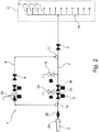
- a vent valve 6 is present on the main line 4, preferably downstream of the sealing device 5.
- the main line 4 branches to reach the first 3a and the second set 3b of nozzles 3.
- the main line comprises a main branch 4a which branches into a primary 4b and into a secondary branch 4c.
- the primary branch 4b is placed in fluid connection with the main branch 4a and with the first set 3a of nozzles 3.
- the secondary branch 4c is placed in fluid connection with the main branch 4a and with the second set 3b of nozzles 3.
- the above described sealing device 5 and vent valve 6 are placed on the main branch 4a of the main line 4.
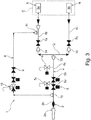
- the auxiliary line 8 connects back to the primary branch 4b of the main line 4, in particular downstream of the expansion zone 12. Similarly to the embodiment shown in figure 2 , the auxiliary line 8 connects to the primary branch 4b downstream of the primary flow regulator 7a. Another variant is possible (not shown in the drawings) in which the auxiliary line 8 connects to the primary branch 4b upstream of the primary flow regulator 7a.
- the auxiliary line 8 is provided with its own auxiliary sealing device 15.
- Such auxiliary sealing device 15 is substantially similar to the sealing device 5 described above.
- the auxiliary line 8 is provided with an auxiliary flow regulator 9, which is configured to vary the flow of fuel on the auxiliary fuel line 9 itself. Indeed, the auxiliary flow regulator 9 ensures that the flow along the auxiliary line 8 can never exceed the auxiliary line 8 maximum flow rate. This maximum flow rate is less than the maximum flow rate of the main line 4.
- the auxiliary flow regulator 9 is in particular placed directly downstream with respect to the auxiliary sealing device 15.
- the exact value of the LEL depends on the phisical/chemical properties of the fuel, on the temperature of the air, and on other general phisical properties so that its precise value can easily be computed by the person skilled in the art if all such properties are known or can be reasonably assumed to be inside a specific range (such as is generally the case during the design of a gas turbine).
- the main line 4 is opened in order to increase the main line 4 fuel flow rate.
- the gas turbine is warmed up for several minutes.
- the sealing device 5 is gradually opened, in particular with reference to the first 5a and second valve 5b.
- the main flow regulator 7 can then be controlled in order to further increase the flow of fuel inside the combustion chamber "C".
Claims (13)
- Procédé de démarrage d'une turbine à gaz, la turbine à gaz comprenant un appareil (1) pour réguler l'écoulement de carburant vers une chambre de combustion (C) dans la turbine à gaz, l'appareil (1) comprenant une ligne principale (4) configurée pour être placée de façon sélectionnable en communication fluidique avec une source de carburant (2) et avec au moins une buse d'un réseau de buses (N) pour transférer du carburant à partir de ladite source de carburant (2) vers l'au moins une buse du réseau de buses (N), dans lequel l'au moins une buse du réseau de buses (N) est configurée pour injecter du carburant dans la chambre de combustion (C), l'appareil comprenant en outre une ligne auxiliaire (8) configurée pour être placée de façon sélectionnable en communication fluidique avec ladite source de carburant (2) et avec l'au moins une buse du réseau de buses (N) pour transférer du carburant à partir de ladite source de carburant (2) vers l'au moins une buse du réseau de buses (N), dans lequel la ligne auxiliaire (8) inclut une première extrémité qui se ramifie à partir de la ligne principale (4) et une deuxième extrémité, en aval de la première extrémité de la ligne auxiliaire (8), qui se reconnecte à la ligne principale (4), la ligne auxiliaire (8) configurée pour diriger sélectivement tout le carburant reçu au niveau de la première extrémité vers la deuxième extrémité, le procédé comprenant :- le maintien de la ligne principale (4) dans un état scellé pour empêcher du carburant de s'écouler de la source de carburant vers l'au moins une buse du réseau de buses par l'intermédiaire de la ligne principale (4) tout en augmentant le débit de carburant de la ligne auxiliaire (8), du carburant s'écoulant de la source de carburant vers l'au moins une buse du réseau de buses (N) par l'intermédiaire de la ligne auxiliaire (8), dans lequel le débit de carburant de ligne auxiliaire est inférieur ou égal à un débit maximal prédéterminé de ligne auxiliaire ;- l'allumage de la turbine à gaz tout en maintenant la ligne principale (4) dans l'état scellé ; et- après que la combustion a démarré dans la chambre de combustion (C), l'ouverture de la ligne principale (4) à partir de l'état scellé pour augmenter un débit de carburant de la ligne principale (4) du carburant s'écoulant de la source de carburant vers l'au moins une buse du réseau de buses à travers la ligne principale (4), dans lequel le débit de carburant de ligne principale est inférieur ou égal à un débit maximal prédéterminé de ligne principale ;dans lequel le débit maximal prédéterminé de la ligne auxiliaire (8) est inférieur au débit maximal prédéterminé de la ligne principale (4) ; et
dans lequel le débit maximal prédéterminé de la ligne auxiliaire (8) est inférieur à 15 % du débit total maximal de carburant, le débit total maximal de carburant étant une somme du débit maximal prédéterminé de ligne auxiliaire et du débit maximal prédéterminé de ligne principale. - Procédé selon la revendication précédente, dans lequel le débit maximal de la ligne auxiliaire (8) est tel que la concentration en carburant est inférieure à la limite inférieure d'explosivité.
- Procédé selon la revendication 1 ou la revendication 2, comprenant également l'étape de détection d'une flamme à l'intérieur de la chambre de combustion (C) avant l'étape d'ouverture de la ligne principale (4).
- Procédé selon la revendication précédente, dans lequel l'écoulement de carburant le long de la ligne principale (4) est augmenté progressivement pour éviter des pics de pression sur la ligne principale (4).
- Procédé selon l'une quelconque des revendications précédentes, dans lequel ledit appareil (1) comprend également un régulateur d'écoulement principal (7) placé dans la ligne principale (4) et configuré pour faire varier l'écoulement de carburant dans la ligne principale (4) jusqu'au débit maximal de ligne principale ; un régulateur d'écoulement auxiliaire (9) placé dans la ligne auxiliaire (8) et configuré pour faire varier l'écoulement de carburant dans la ligne auxiliaire (8) jusqu'au débit maximal de la ligne auxiliaire (8).
- Procédé selon la revendication précédente, dans lequel le régulateur d'écoulement auxiliaire (9) est un orifice.
- Procédé selon la revendication 5 ou 6, dans lequel la ligne auxiliaire (8) est connectée à la ligne principale (4) en amont du régulateur d'écoulement principal (7) pour améliorer la faible capacité de commande d'écoulement du régulateur d'écoulement principal (7) en réduisant sa pression en amont.
- Procédé selon la revendication précédente, comprenant en outre l'étape de commande dudit régulateur d'écoulement auxiliaire (9) pour obtenir une valeur de pression prédéterminée en amont dudit régulateur d'écoulement principal (7).
- Procédé selon la revendication précédente, dans lequel ladite valeur de pression prédéterminée est une fonction de la vitesse de rotation de la turbomachine.
- Procédé selon la revendication 5 ou 6, dans lequel la ligne auxiliaire (8) est connectée à la ligne principale (4) en aval du régulateur d'écoulement principal (7).
- Procédé selon la revendication précédente, comprenant en outre l'étape de commande dudit régulateur d'écoulement auxiliaire (9) pour obtenir un débit prédéterminé le long de ladite ligne auxiliaire (8).
- Procédé selon la revendication 10 ou 11, dans lequel l'appareil (1) comprend également un dispositif de scellage (5) en amont du régulateur d'écoulement principal (7), le procédé comprenant également les étapes d'ouverture dudit régulateur d'écoulement principal (7) à une course prédéfinie, d'ouverture progressive dudit dispositif de scellage (5) tout en réduisant le débit de la ligne auxiliaire (8) pour maintenir le débit total essentiellement constant pendant l'ouverture du dispositif de scellage (5).
- Appareil (1) pour réguler l'écoulement de carburant vers une chambre de combustion (C) dans une turbine à gaz, l'appareil (1) comprenant une ligne principale (4) configurée pour être placée de façon sélectionnable en communication fluidique avec une source de carburant (2) et avec au moins une buse d'un réseau de buses (N) pour transférer du carburant à partir de ladite source de carburant (2) vers l'au moins une buse du réseau de buses (N), dans lequel l'au moins une buse du réseau de buses (N) est configurée pour injecter du carburant dans la chambre de combustion (C), l'appareil comprenant en outre une ligne auxiliaire (8) configurée pour être placée de façon sélectionnable en communication fluidique avec ladite source de carburant (2) et avec l'au moins une buse du réseau de buses (N) pour transférer du carburant à partir de ladite source de carburant (2) vers l'au moins une buse du réseau de buses (N), dans lequel la ligne auxiliaire (8) inclut une première extrémité qui se ramifie à partir de la ligne principale (4) et une deuxième extrémité, en aval de la première extrémité de la ligne auxiliaire (8), qui se reconnecte à la ligne principale (4), la ligne auxiliaire (8) configurée pour diriger sélectivement tout le carburant reçu au niveau de la première extrémité vers la deuxième extrémité, l'appareil étant agencé pour être mis en oeuvre pour démarrer la turbine à gaz par le procédé de l'une quelconque des revendications précédentes.
Applications Claiming Priority (2)
| Application Number | Priority Date | Filing Date | Title |
|---|---|---|---|
| ITCO20140007 | 2014-03-18 | ||
| PCT/EP2015/055647 WO2015140200A1 (fr) | 2014-03-18 | 2015-03-18 | Procédé de démarrage d'une turbine à gaz |
Publications (2)
| Publication Number | Publication Date |
|---|---|
| EP3120003A1 EP3120003A1 (fr) | 2017-01-25 |
| EP3120003B1 true EP3120003B1 (fr) | 2021-04-28 |
Family
ID=50693754
Family Applications (1)
| Application Number | Title | Priority Date | Filing Date |
|---|---|---|---|
| EP15710776.4A Active EP3120003B1 (fr) | 2014-03-18 | 2015-03-18 | Procédé et appareil de démarrage d'une turbine à gaz |
Country Status (7)
| Country | Link |
|---|---|
| US (1) | US10533503B2 (fr) |
| EP (1) | EP3120003B1 (fr) |
| JP (2) | JP2017518453A (fr) |
| AU (1) | AU2015233563B2 (fr) |
| BR (1) | BR112016020810B1 (fr) |
| CA (1) | CA2942835C (fr) |
| WO (1) | WO2015140200A1 (fr) |
Families Citing this family (4)
| Publication number | Priority date | Publication date | Assignee | Title |
|---|---|---|---|---|
| US11459959B2 (en) * | 2016-09-16 | 2022-10-04 | General Electric Company | Method for starting a gas turbine |
| IT201700073686A1 (it) * | 2017-06-30 | 2018-12-30 | Nuovo Pignone Tecnologie Srl | Metodo e sistema per l'avvio sicuro di turbine a gas |
| US11506125B2 (en) * | 2018-08-01 | 2022-11-22 | General Electric Company | Fluid manifold assembly for gas turbine engine |
| WO2023140045A1 (fr) * | 2022-01-24 | 2023-07-27 | 三菱重工業株式会社 | Dispositif de commande de turbine à gaz, turbine à gaz et procédé de commande de turbine à gaz |
Citations (3)
| Publication number | Priority date | Publication date | Assignee | Title |
|---|---|---|---|---|
| JP2000008877A (ja) * | 1998-06-29 | 2000-01-11 | Toyota Central Res & Dev Lab Inc | 燃焼器の流体供給装置 |
| EP1985822A2 (fr) * | 2007-04-19 | 2008-10-29 | Pratt & Whitney Canada Corp. | Mesure d'écoulement de carburant au démarrage |
| US20130055719A1 (en) * | 2010-03-26 | 2013-03-07 | Kawasaki Jukogyo Kabushiki Kaisha | Fuel supply device of gas turbine engine |
Family Cites Families (22)
| Publication number | Priority date | Publication date | Assignee | Title |
|---|---|---|---|---|
| US2971575A (en) | 1955-04-14 | 1961-02-14 | Bendix Corp | Fuel flow control for engines |
| US3729929A (en) | 1971-03-09 | 1973-05-01 | Westinghouse Electric Corp | Fuel control system for a gas turbine |
| JPS5171411A (fr) * | 1974-12-18 | 1976-06-21 | Hitachi Ltd | |
| JPS55161921A (en) | 1979-06-04 | 1980-12-16 | Nissan Motor Co Ltd | Fuel control device for gas turbine engine |
| US4292801A (en) * | 1979-07-11 | 1981-10-06 | General Electric Company | Dual stage-dual mode low nox combustor |
| JPS61207830A (ja) * | 1985-03-12 | 1986-09-16 | Hitachi Ltd | ブラツクスタ−ト用のガスタ−ビン燃料ガス昇圧装置 |
| US5095221A (en) | 1989-11-03 | 1992-03-10 | Westinghouse Electric Corp. | Gas turbine control system having partial hood control |
| JPH07224688A (ja) * | 1994-02-09 | 1995-08-22 | Mitsubishi Heavy Ind Ltd | ガスタービンの燃料供給方法 |
| AU730820B2 (en) | 1995-12-26 | 2001-03-15 | Kabushiki Kaisha Toshiba | Fuel supply apparatus for gas turbine and control unit for the same |
| JP2002364384A (ja) * | 2001-06-05 | 2002-12-18 | Nishishiba Electric Co Ltd | ガスタービンの燃料供給方法 |
| US6810677B2 (en) * | 2001-08-27 | 2004-11-02 | Elliot Energy Systems, Inc. | Method for gas turbine light-off |
| US7036302B2 (en) | 2004-03-15 | 2006-05-02 | General Electric Company | Controlled pressure fuel nozzle system |
| JP4119909B2 (ja) * | 2005-09-14 | 2008-07-16 | 三菱重工業株式会社 | ガスタービンの燃焼制御装置 |
| JP4119908B2 (ja) | 2005-09-14 | 2008-07-16 | 三菱重工業株式会社 | ガスタービンの燃焼制御装置 |
| US7481061B2 (en) | 2005-11-10 | 2009-01-27 | Siemens Energy, Inc. | Fuel control for starting a gas turbine engine |
| JP4831820B2 (ja) * | 2006-05-22 | 2011-12-07 | 三菱重工業株式会社 | ガスタービン出力学習回路及びこれを備えたガスタービンの燃焼制御装置 |
| US8820087B2 (en) | 2008-09-08 | 2014-09-02 | Siemens Energy, Inc. | Method and system for controlling fuel to a dual stage nozzle |
| US8015791B2 (en) | 2008-11-18 | 2011-09-13 | General Electric Company | Fuel control system for gas turbine and feed forward control method |
| JP5529676B2 (ja) * | 2010-08-20 | 2014-06-25 | 三菱重工業株式会社 | ガスタービン燃焼器の燃料供給系統およびガスタービン燃焼器の燃料供給方法 |
| US8744634B2 (en) * | 2010-11-19 | 2014-06-03 | General Electric Company | Safety instrumented system (SIS) for a turbine system |
| US9070730B2 (en) | 2011-10-07 | 2015-06-30 | Varian Semiconductor Equipment Associates, Inc. | Method and apparatus for removing a vertically-oriented substrate from a cassette |
| DE112012005659B4 (de) * | 2012-01-13 | 2024-01-18 | Mitsubishi Heavy Industries, Ltd. | Brennstoff-Zufuhrvorrichtung, Brennstoff-Strömungsratensteuereinheit und Gasturbinenkraftwerk |
-
2015
- 2015-03-18 AU AU2015233563A patent/AU2015233563B2/en not_active Ceased
- 2015-03-18 JP JP2016556853A patent/JP2017518453A/ja active Pending
- 2015-03-18 WO PCT/EP2015/055647 patent/WO2015140200A1/fr active Application Filing
- 2015-03-18 EP EP15710776.4A patent/EP3120003B1/fr active Active
- 2015-03-18 BR BR112016020810-2A patent/BR112016020810B1/pt not_active IP Right Cessation
- 2015-03-18 CA CA2942835A patent/CA2942835C/fr active Active
- 2015-03-18 US US15/126,629 patent/US10533503B2/en active Active
-
2020
- 2020-05-28 JP JP2020093428A patent/JP7073445B2/ja active Active
Patent Citations (3)
| Publication number | Priority date | Publication date | Assignee | Title |
|---|---|---|---|---|
| JP2000008877A (ja) * | 1998-06-29 | 2000-01-11 | Toyota Central Res & Dev Lab Inc | 燃焼器の流体供給装置 |
| EP1985822A2 (fr) * | 2007-04-19 | 2008-10-29 | Pratt & Whitney Canada Corp. | Mesure d'écoulement de carburant au démarrage |
| US20130055719A1 (en) * | 2010-03-26 | 2013-03-07 | Kawasaki Jukogyo Kabushiki Kaisha | Fuel supply device of gas turbine engine |
Also Published As
| Publication number | Publication date |
|---|---|
| BR112016020810B1 (pt) | 2022-03-15 |
| CA2942835C (fr) | 2022-11-08 |
| CA2942835A1 (fr) | 2015-09-24 |
| WO2015140200A1 (fr) | 2015-09-24 |
| JP2017518453A (ja) | 2017-07-06 |
| BR112016020810A2 (fr) | 2017-08-15 |
| JP7073445B2 (ja) | 2022-05-23 |
| EP3120003A1 (fr) | 2017-01-25 |
| AU2015233563B2 (en) | 2018-11-01 |
| AU2015233563A1 (en) | 2016-09-29 |
| JP2020143672A (ja) | 2020-09-10 |
| US20170074174A1 (en) | 2017-03-16 |
| US10533503B2 (en) | 2020-01-14 |
Similar Documents
| Publication | Publication Date | Title |
|---|---|---|
| US11459959B2 (en) | Method for starting a gas turbine | |
| JP7073445B2 (ja) | ガスタービンを始動させるための方法 | |
| EP2843211B1 (fr) | Turbine à gaz présentant un meilleur comportement d'émissions de charge partielle et procédé de fonctionnement | |
| EP3208443B1 (fr) | Système de combustion étagé | |
| EP3061949B1 (fr) | Système de combustion étagée | |
| GB2563659B (en) | Combustion staging system for fuel injectors of a gas turbine engine | |
| EP3217000B1 (fr) | Système d'activation de combustion | |
| EP3735560B1 (fr) | Chambre de combustion de turbine à gaz comprenant une torche d'allumage et méthode pour alimenter une torche d'allumage en carburant | |
| US20180163636A1 (en) | Fuel supply system | |
| US10982858B2 (en) | Combustion staging system | |
| EP4123145A1 (fr) | Moteur polycarburant pour aéronef | |
| EP2762709B1 (fr) | Procédé d'exploitation d'un système de chauffage à combustible | |
| US8844295B2 (en) | Method for meeting a purge flow requirement for a power plant and a power plant having a purge control system | |
| EP3171005B1 (fr) | Système d'alimentation en carburant destiné à être utilisé dans un moteur à turbine à gaz et procédé de commande d'un événement de survitesse dans celui-ci | |
| EP2746555B1 (fr) | Système d'alimentation en carburant pour une turbine à gaz et procédé d'alimentation en carburant | |
| JP2011144806A (ja) | ガスタービンエンジンで使用するための燃料制御アセンブリシステム及び装置 |
Legal Events
| Date | Code | Title | Description |
|---|---|---|---|
| STAA | Information on the status of an ep patent application or granted ep patent |
Free format text: STATUS: THE INTERNATIONAL PUBLICATION HAS BEEN MADE |
|
| PUAI | Public reference made under article 153(3) epc to a published international application that has entered the european phase |
Free format text: ORIGINAL CODE: 0009012 |
|
| STAA | Information on the status of an ep patent application or granted ep patent |
Free format text: STATUS: REQUEST FOR EXAMINATION WAS MADE |
|
| 17P | Request for examination filed |
Effective date: 20161018 |
|
| AK | Designated contracting states |
Kind code of ref document: A1 Designated state(s): AL AT BE BG CH CY CZ DE DK EE ES FI FR GB GR HR HU IE IS IT LI LT LU LV MC MK MT NL NO PL PT RO RS SE SI SK SM TR |
|
| AX | Request for extension of the european patent |
Extension state: BA ME |
|
| DAV | Request for validation of the european patent (deleted) | ||
| DAX | Request for extension of the european patent (deleted) | ||
| STAA | Information on the status of an ep patent application or granted ep patent |
Free format text: STATUS: EXAMINATION IS IN PROGRESS |
|
| 17Q | First examination report despatched |
Effective date: 20200417 |
|
| GRAP | Despatch of communication of intention to grant a patent |
Free format text: ORIGINAL CODE: EPIDOSNIGR1 |
|
| STAA | Information on the status of an ep patent application or granted ep patent |
Free format text: STATUS: GRANT OF PATENT IS INTENDED |
|
| INTG | Intention to grant announced |
Effective date: 20201118 |
|
| GRAS | Grant fee paid |
Free format text: ORIGINAL CODE: EPIDOSNIGR3 |
|
| GRAA | (expected) grant |
Free format text: ORIGINAL CODE: 0009210 |
|
| STAA | Information on the status of an ep patent application or granted ep patent |
Free format text: STATUS: THE PATENT HAS BEEN GRANTED |
|
| AK | Designated contracting states |
Kind code of ref document: B1 Designated state(s): AL AT BE BG CH CY CZ DE DK EE ES FI FR GB GR HR HU IE IS IT LI LT LU LV MC MK MT NL NO PL PT RO RS SE SI SK SM TR |
|
| REG | Reference to a national code |
Ref country code: GB Ref legal event code: FG4D |
|
| REG | Reference to a national code |
Ref country code: CH Ref legal event code: EP |
|
| REG | Reference to a national code |
Ref country code: AT Ref legal event code: REF Ref document number: 1387305 Country of ref document: AT Kind code of ref document: T Effective date: 20210515 |
|
| REG | Reference to a national code |
Ref country code: DE Ref legal event code: R096 Ref document number: 602015068613 Country of ref document: DE |
|
| REG | Reference to a national code |
Ref country code: IE Ref legal event code: FG4D |
|
| REG | Reference to a national code |
Ref country code: LT Ref legal event code: MG9D |
|
| REG | Reference to a national code |
Ref country code: AT Ref legal event code: MK05 Ref document number: 1387305 Country of ref document: AT Kind code of ref document: T Effective date: 20210428 |
|
| PG25 | Lapsed in a contracting state [announced via postgrant information from national office to epo] |
Ref country code: FI Free format text: LAPSE BECAUSE OF FAILURE TO SUBMIT A TRANSLATION OF THE DESCRIPTION OR TO PAY THE FEE WITHIN THE PRESCRIBED TIME-LIMIT Effective date: 20210428 Ref country code: LT Free format text: LAPSE BECAUSE OF FAILURE TO SUBMIT A TRANSLATION OF THE DESCRIPTION OR TO PAY THE FEE WITHIN THE PRESCRIBED TIME-LIMIT Effective date: 20210428 Ref country code: NL Free format text: LAPSE BECAUSE OF FAILURE TO SUBMIT A TRANSLATION OF THE DESCRIPTION OR TO PAY THE FEE WITHIN THE PRESCRIBED TIME-LIMIT Effective date: 20210428 Ref country code: BG Free format text: LAPSE BECAUSE OF FAILURE TO SUBMIT A TRANSLATION OF THE DESCRIPTION OR TO PAY THE FEE WITHIN THE PRESCRIBED TIME-LIMIT Effective date: 20210728 Ref country code: AT Free format text: LAPSE BECAUSE OF FAILURE TO SUBMIT A TRANSLATION OF THE DESCRIPTION OR TO PAY THE FEE WITHIN THE PRESCRIBED TIME-LIMIT Effective date: 20210428 Ref country code: HR Free format text: LAPSE BECAUSE OF FAILURE TO SUBMIT A TRANSLATION OF THE DESCRIPTION OR TO PAY THE FEE WITHIN THE PRESCRIBED TIME-LIMIT Effective date: 20210428 |
|
| PG25 | Lapsed in a contracting state [announced via postgrant information from national office to epo] |
Ref country code: IS Free format text: LAPSE BECAUSE OF FAILURE TO SUBMIT A TRANSLATION OF THE DESCRIPTION OR TO PAY THE FEE WITHIN THE PRESCRIBED TIME-LIMIT Effective date: 20210828 Ref country code: LV Free format text: LAPSE BECAUSE OF FAILURE TO SUBMIT A TRANSLATION OF THE DESCRIPTION OR TO PAY THE FEE WITHIN THE PRESCRIBED TIME-LIMIT Effective date: 20210428 Ref country code: GR Free format text: LAPSE BECAUSE OF FAILURE TO SUBMIT A TRANSLATION OF THE DESCRIPTION OR TO PAY THE FEE WITHIN THE PRESCRIBED TIME-LIMIT Effective date: 20210729 Ref country code: ES Free format text: LAPSE BECAUSE OF FAILURE TO SUBMIT A TRANSLATION OF THE DESCRIPTION OR TO PAY THE FEE WITHIN THE PRESCRIBED TIME-LIMIT Effective date: 20210428 Ref country code: PT Free format text: LAPSE BECAUSE OF FAILURE TO SUBMIT A TRANSLATION OF THE DESCRIPTION OR TO PAY THE FEE WITHIN THE PRESCRIBED TIME-LIMIT Effective date: 20210830 Ref country code: PL Free format text: LAPSE BECAUSE OF FAILURE TO SUBMIT A TRANSLATION OF THE DESCRIPTION OR TO PAY THE FEE WITHIN THE PRESCRIBED TIME-LIMIT Effective date: 20210428 Ref country code: NO Free format text: LAPSE BECAUSE OF FAILURE TO SUBMIT A TRANSLATION OF THE DESCRIPTION OR TO PAY THE FEE WITHIN THE PRESCRIBED TIME-LIMIT Effective date: 20210728 Ref country code: SE Free format text: LAPSE BECAUSE OF FAILURE TO SUBMIT A TRANSLATION OF THE DESCRIPTION OR TO PAY THE FEE WITHIN THE PRESCRIBED TIME-LIMIT Effective date: 20210428 Ref country code: RS Free format text: LAPSE BECAUSE OF FAILURE TO SUBMIT A TRANSLATION OF THE DESCRIPTION OR TO PAY THE FEE WITHIN THE PRESCRIBED TIME-LIMIT Effective date: 20210428 |
|
| REG | Reference to a national code |
Ref country code: NL Ref legal event code: MP Effective date: 20210428 |
|
| PG25 | Lapsed in a contracting state [announced via postgrant information from national office to epo] |
Ref country code: RO Free format text: LAPSE BECAUSE OF FAILURE TO SUBMIT A TRANSLATION OF THE DESCRIPTION OR TO PAY THE FEE WITHIN THE PRESCRIBED TIME-LIMIT Effective date: 20210428 Ref country code: DK Free format text: LAPSE BECAUSE OF FAILURE TO SUBMIT A TRANSLATION OF THE DESCRIPTION OR TO PAY THE FEE WITHIN THE PRESCRIBED TIME-LIMIT Effective date: 20210428 Ref country code: EE Free format text: LAPSE BECAUSE OF FAILURE TO SUBMIT A TRANSLATION OF THE DESCRIPTION OR TO PAY THE FEE WITHIN THE PRESCRIBED TIME-LIMIT Effective date: 20210428 Ref country code: CZ Free format text: LAPSE BECAUSE OF FAILURE TO SUBMIT A TRANSLATION OF THE DESCRIPTION OR TO PAY THE FEE WITHIN THE PRESCRIBED TIME-LIMIT Effective date: 20210428 Ref country code: SK Free format text: LAPSE BECAUSE OF FAILURE TO SUBMIT A TRANSLATION OF THE DESCRIPTION OR TO PAY THE FEE WITHIN THE PRESCRIBED TIME-LIMIT Effective date: 20210428 Ref country code: SM Free format text: LAPSE BECAUSE OF FAILURE TO SUBMIT A TRANSLATION OF THE DESCRIPTION OR TO PAY THE FEE WITHIN THE PRESCRIBED TIME-LIMIT Effective date: 20210428 |
|
| REG | Reference to a national code |
Ref country code: DE Ref legal event code: R097 Ref document number: 602015068613 Country of ref document: DE |
|
| PLBE | No opposition filed within time limit |
Free format text: ORIGINAL CODE: 0009261 |
|
| STAA | Information on the status of an ep patent application or granted ep patent |
Free format text: STATUS: NO OPPOSITION FILED WITHIN TIME LIMIT |
|
| 26N | No opposition filed |
Effective date: 20220131 |
|
| PG25 | Lapsed in a contracting state [announced via postgrant information from national office to epo] |
Ref country code: IS Free format text: LAPSE BECAUSE OF FAILURE TO SUBMIT A TRANSLATION OF THE DESCRIPTION OR TO PAY THE FEE WITHIN THE PRESCRIBED TIME-LIMIT Effective date: 20210828 Ref country code: AL Free format text: LAPSE BECAUSE OF FAILURE TO SUBMIT A TRANSLATION OF THE DESCRIPTION OR TO PAY THE FEE WITHIN THE PRESCRIBED TIME-LIMIT Effective date: 20210428 |
|
| PG25 | Lapsed in a contracting state [announced via postgrant information from national office to epo] |
Ref country code: IT Free format text: LAPSE BECAUSE OF FAILURE TO SUBMIT A TRANSLATION OF THE DESCRIPTION OR TO PAY THE FEE WITHIN THE PRESCRIBED TIME-LIMIT Effective date: 20210428 |
|
| PG25 | Lapsed in a contracting state [announced via postgrant information from national office to epo] |
Ref country code: MC Free format text: LAPSE BECAUSE OF FAILURE TO SUBMIT A TRANSLATION OF THE DESCRIPTION OR TO PAY THE FEE WITHIN THE PRESCRIBED TIME-LIMIT Effective date: 20210428 |
|
| REG | Reference to a national code |
Ref country code: CH Ref legal event code: PL |
|
| GBPC | Gb: european patent ceased through non-payment of renewal fee |
Effective date: 20220318 |
|
| REG | Reference to a national code |
Ref country code: BE Ref legal event code: MM Effective date: 20220331 |
|
| PG25 | Lapsed in a contracting state [announced via postgrant information from national office to epo] |
Ref country code: LU Free format text: LAPSE BECAUSE OF NON-PAYMENT OF DUE FEES Effective date: 20220318 Ref country code: LI Free format text: LAPSE BECAUSE OF NON-PAYMENT OF DUE FEES Effective date: 20220331 Ref country code: IE Free format text: LAPSE BECAUSE OF NON-PAYMENT OF DUE FEES Effective date: 20220318 Ref country code: GB Free format text: LAPSE BECAUSE OF NON-PAYMENT OF DUE FEES Effective date: 20220318 Ref country code: FR Free format text: LAPSE BECAUSE OF NON-PAYMENT OF DUE FEES Effective date: 20220331 Ref country code: CH Free format text: LAPSE BECAUSE OF NON-PAYMENT OF DUE FEES Effective date: 20220331 |
|
| PG25 | Lapsed in a contracting state [announced via postgrant information from national office to epo] |
Ref country code: BE Free format text: LAPSE BECAUSE OF NON-PAYMENT OF DUE FEES Effective date: 20220331 |
|
| PGFP | Annual fee paid to national office [announced via postgrant information from national office to epo] |
Ref country code: DE Payment date: 20230221 Year of fee payment: 9 |
|
| PG25 | Lapsed in a contracting state [announced via postgrant information from national office to epo] |
Ref country code: HU Free format text: LAPSE BECAUSE OF FAILURE TO SUBMIT A TRANSLATION OF THE DESCRIPTION OR TO PAY THE FEE WITHIN THE PRESCRIBED TIME-LIMIT; INVALID AB INITIO Effective date: 20150318 |
|
| PG25 | Lapsed in a contracting state [announced via postgrant information from national office to epo] |
Ref country code: MK Free format text: LAPSE BECAUSE OF FAILURE TO SUBMIT A TRANSLATION OF THE DESCRIPTION OR TO PAY THE FEE WITHIN THE PRESCRIBED TIME-LIMIT Effective date: 20210428 Ref country code: CY Free format text: LAPSE BECAUSE OF FAILURE TO SUBMIT A TRANSLATION OF THE DESCRIPTION OR TO PAY THE FEE WITHIN THE PRESCRIBED TIME-LIMIT Effective date: 20210428 |
|
| PGFP | Annual fee paid to national office [announced via postgrant information from national office to epo] |
Ref country code: DE Payment date: 20240220 Year of fee payment: 10 |