EP2746555B1 - Système d'alimentation en carburant pour une turbine à gaz et procédé d'alimentation en carburant - Google Patents
Système d'alimentation en carburant pour une turbine à gaz et procédé d'alimentation en carburant Download PDFInfo
- Publication number
- EP2746555B1 EP2746555B1 EP13196431.4A EP13196431A EP2746555B1 EP 2746555 B1 EP2746555 B1 EP 2746555B1 EP 13196431 A EP13196431 A EP 13196431A EP 2746555 B1 EP2746555 B1 EP 2746555B1
- Authority
- EP
- European Patent Office
- Prior art keywords
- fuel
- nozzles
- circuit
- gas turbine
- primary
- Prior art date
- Legal status (The legal status is an assumption and is not a legal conclusion. Google has not performed a legal analysis and makes no representation as to the accuracy of the status listed.)
- Active
Links
- 239000000446 fuel Substances 0.000 title claims description 209
- 238000000034 method Methods 0.000 title claims description 13
- 238000002347 injection Methods 0.000 claims 1
- 239000007924 injection Substances 0.000 claims 1
- 239000007789 gas Substances 0.000 description 28
- 238000002485 combustion reaction Methods 0.000 description 4
- 230000001052 transient effect Effects 0.000 description 3
- 238000010586 diagram Methods 0.000 description 2
- VNWKTOKETHGBQD-UHFFFAOYSA-N methane Chemical compound C VNWKTOKETHGBQD-UHFFFAOYSA-N 0.000 description 2
- 239000000203 mixture Substances 0.000 description 2
- 230000001627 detrimental effect Effects 0.000 description 1
- 239000012530 fluid Substances 0.000 description 1
- 239000007788 liquid Substances 0.000 description 1
- 239000003345 natural gas Substances 0.000 description 1
- 230000007704 transition Effects 0.000 description 1
Images


Classifications
-
- F—MECHANICAL ENGINEERING; LIGHTING; HEATING; WEAPONS; BLASTING
- F02—COMBUSTION ENGINES; HOT-GAS OR COMBUSTION-PRODUCT ENGINE PLANTS
- F02C—GAS-TURBINE PLANTS; AIR INTAKES FOR JET-PROPULSION PLANTS; CONTROLLING FUEL SUPPLY IN AIR-BREATHING JET-PROPULSION PLANTS
- F02C9/00—Controlling gas-turbine plants; Controlling fuel supply in air- breathing jet-propulsion plants
- F02C9/26—Control of fuel supply
- F02C9/263—Control of fuel supply by means of fuel metering valves
-
- F—MECHANICAL ENGINEERING; LIGHTING; HEATING; WEAPONS; BLASTING
- F02—COMBUSTION ENGINES; HOT-GAS OR COMBUSTION-PRODUCT ENGINE PLANTS
- F02C—GAS-TURBINE PLANTS; AIR INTAKES FOR JET-PROPULSION PLANTS; CONTROLLING FUEL SUPPLY IN AIR-BREATHING JET-PROPULSION PLANTS
- F02C7/00—Features, components parts, details or accessories, not provided for in, or of interest apart form groups F02C1/00 - F02C6/00; Air intakes for jet-propulsion plants
- F02C7/22—Fuel supply systems
- F02C7/222—Fuel flow conduits, e.g. manifolds
-
- F—MECHANICAL ENGINEERING; LIGHTING; HEATING; WEAPONS; BLASTING
- F02—COMBUSTION ENGINES; HOT-GAS OR COMBUSTION-PRODUCT ENGINE PLANTS
- F02C—GAS-TURBINE PLANTS; AIR INTAKES FOR JET-PROPULSION PLANTS; CONTROLLING FUEL SUPPLY IN AIR-BREATHING JET-PROPULSION PLANTS
- F02C9/00—Controlling gas-turbine plants; Controlling fuel supply in air- breathing jet-propulsion plants
- F02C9/26—Control of fuel supply
- F02C9/28—Regulating systems responsive to plant or ambient parameters, e.g. temperature, pressure, rotor speed
-
- F—MECHANICAL ENGINEERING; LIGHTING; HEATING; WEAPONS; BLASTING
- F23—COMBUSTION APPARATUS; COMBUSTION PROCESSES
- F23K—FEEDING FUEL TO COMBUSTION APPARATUS
- F23K5/00—Feeding or distributing other fuel to combustion apparatus
- F23K5/02—Liquid fuel
- F23K5/06—Liquid fuel from a central source to a plurality of burners
-
- F—MECHANICAL ENGINEERING; LIGHTING; HEATING; WEAPONS; BLASTING
- F23—COMBUSTION APPARATUS; COMBUSTION PROCESSES
- F23K—FEEDING FUEL TO COMBUSTION APPARATUS
- F23K5/00—Feeding or distributing other fuel to combustion apparatus
- F23K5/02—Liquid fuel
- F23K5/14—Details thereof
-
- F—MECHANICAL ENGINEERING; LIGHTING; HEATING; WEAPONS; BLASTING
- F23—COMBUSTION APPARATUS; COMBUSTION PROCESSES
- F23R—GENERATING COMBUSTION PRODUCTS OF HIGH PRESSURE OR HIGH VELOCITY, e.g. GAS-TURBINE COMBUSTION CHAMBERS
- F23R3/00—Continuous combustion chambers using liquid or gaseous fuel
- F23R3/28—Continuous combustion chambers using liquid or gaseous fuel characterised by the fuel supply
- F23R3/34—Feeding into different combustion zones
-
- F—MECHANICAL ENGINEERING; LIGHTING; HEATING; WEAPONS; BLASTING
- F02—COMBUSTION ENGINES; HOT-GAS OR COMBUSTION-PRODUCT ENGINE PLANTS
- F02C—GAS-TURBINE PLANTS; AIR INTAKES FOR JET-PROPULSION PLANTS; CONTROLLING FUEL SUPPLY IN AIR-BREATHING JET-PROPULSION PLANTS
- F02C7/00—Features, components parts, details or accessories, not provided for in, or of interest apart form groups F02C1/00 - F02C6/00; Air intakes for jet-propulsion plants
- F02C7/22—Fuel supply systems
- F02C7/228—Dividing fuel between various burners
-
- F—MECHANICAL ENGINEERING; LIGHTING; HEATING; WEAPONS; BLASTING
- F02—COMBUSTION ENGINES; HOT-GAS OR COMBUSTION-PRODUCT ENGINE PLANTS
- F02C—GAS-TURBINE PLANTS; AIR INTAKES FOR JET-PROPULSION PLANTS; CONTROLLING FUEL SUPPLY IN AIR-BREATHING JET-PROPULSION PLANTS
- F02C9/00—Controlling gas-turbine plants; Controlling fuel supply in air- breathing jet-propulsion plants
- F02C9/26—Control of fuel supply
- F02C9/32—Control of fuel supply characterised by throttling of fuel
- F02C9/34—Joint control of separate flows to main and auxiliary burners
-
- F—MECHANICAL ENGINEERING; LIGHTING; HEATING; WEAPONS; BLASTING
- F05—INDEXING SCHEMES RELATING TO ENGINES OR PUMPS IN VARIOUS SUBCLASSES OF CLASSES F01-F04
- F05D—INDEXING SCHEME FOR ASPECTS RELATING TO NON-POSITIVE-DISPLACEMENT MACHINES OR ENGINES, GAS-TURBINES OR JET-PROPULSION PLANTS
- F05D2220/00—Application
- F05D2220/70—Application in combination with
- F05D2220/76—Application in combination with an electrical generator
-
- F—MECHANICAL ENGINEERING; LIGHTING; HEATING; WEAPONS; BLASTING
- F23—COMBUSTION APPARATUS; COMBUSTION PROCESSES
- F23K—FEEDING FUEL TO COMBUSTION APPARATUS
- F23K2300/00—Pretreatment and supply of liquid fuel
- F23K2300/20—Supply line arrangements
Definitions
- the subject matter disclosed herein relates to gas turbine engines, and more particularly to a fuel routing system of such gas turbine engines, as well as a method of routing fuel therein.
- Gas turbine engines are often connected to an electrical load, such as a generator for supplying electrical power.
- Significant generator speed overshoot may occur if the electrical load is instantaneously removed, thereby causing a transient condition.
- the transient condition may take place when either a utility breaker to an external grid or the generator breaker trips to an open state.
- Generator speed overshoot may cause damage to associated equipment as a result of over-frequency of the generator.
- control of the gas turbine engine will command an emergency shutdown and force an operator to conduct a time consuming and costly gas turbine engine restart cycle.
- EP 1 278014 describes a fuel delivery system for a combustor having injectors supplied by first and second manifolds.
- a fuel routing system of a gas turbine engine includes a primary fuel circuit feeding a fuel distribution manifold which directs fuel to a combustion chamber. Also included is a secondary fuel circuit extending from the primary fuel circuit to a plurality of fuel nozzles configured to direct fuel to the combustor chamber. Further included is a main fuel flow control valve disposed in the primary fuel circuit for restricting fuel flow to the fuel distribution manifold upon removal of an electrical load operably coupled to the gas turbine engine. Yet further included is a plurality of check valves located between the secondary fuel circuit and the primary fuel circuit for restricting the fuel flow from the secondary fuel circuit to the primary fuel circuit.
- a method of routing fuel in a gas turbine engine includes determining that an electrical load operably coupled to the gas turbine engine has been removed. Also included is closing a main fuel flow control valve for restricting a fuel flow along a primary fuel circuit to a fuel distribution manifold. Further included is routing a fuel to a secondary fuel circuit in communication with a plurality of fuel nozzles comprising a subset of a total number of fuel nozzles of the gas turbine engine.
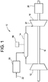
- the gas turbine engine 10 includes a compressor section 12, a combustor section 14, a turbine section 16, a rotor 18 and a fuel nozzle arrangement 20. It is to be appreciated that one embodiment of the gas turbine engine 10 may include a plurality of compressor sections 12, combustor sections 14, turbine sections 16, rotors 18 and fuel nozzle arrangements 20.
- the compressor section 12 and the turbine section 16 are coupled by the rotor 18.
- the rotor 18 may be a single rotor or a plurality of rotor segments coupled together to form the rotor 18.
- the combustor section 14 uses a combustible liquid and/or gas fuel, such as natural gas or a synthetic gas, to run the gas turbine engine 10.
- the fuel nozzle arrangement 20 is in fluid communication with an air supply and a fuel supply 22.
- the fuel nozzle arrangement 20 creates an air-fuel mixture, and discharges the air-fuel mixture into the combustor section 14, thereby causing a combustion that creates a hot pressurized exhaust gas.
- the combustor section 14 directs the hot pressurized gas through a transition piece into a turbine nozzle (or "stage one nozzle"), and other stages of buckets and nozzles causing rotation of the turbine section 16 within a turbine casing 24.
- Rotation of the turbine section 16 causes the rotor 18 to rotate, thereby compressing the air as it flows into the compressor section 12. Additionally, the rotor 18 may be operably coupled to an electrical load 26, such as a generator, configured to convert the mechanical rotational power of the rotor 18 into electrical power.
- an electrical load 26 such as a generator
- the fuel routing system 30 includes the fuel supply 22 and the fuel nozzle arrangement 20 described above.
- a primary fuel circuit 32 is shown and extends from the fuel supply 22 to a fuel distribution manifold 34 configured to deliver fuel to the fuel nozzle arrangement 20.
- the fuel nozzle arrangement 20 comprises a total number of fuel nozzles that may range depending on the type of the gas turbine engine 10 that the fuel nozzle arrangement 20 is associated with. In one embodiment, the total number of fuel nozzles ranges from about 10 to about 100 fuel nozzles. In another embodiment, the total number of fuel nozzles ranges from about 30 to about 36 fuel nozzles.
- fuel is routed through the primary fuel circuit 32, which may include a number of associated components for routing and treating the fuel during passage to the combustion chamber(s) 14.
- the primary fuel circuit 32 may include a number of associated components for routing and treating the fuel during passage to the combustion chamber(s) 14.
- at least one pump or compressor 36, a heater 38, a main fuel flow control valve 41, and one or more shutoff valves 40 may be included at various positions along the primary fuel circuit 32.
- at least one vent line 42 may be included to selectively vent contents of the primary fuel circuit 32 to an external location, such as the atmosphere. Additional components may be included and the preceding examples are merely illustrative.
- a secondary fuel circuit 50 branches off of the primary fuel circuit 32 and extends between the primary fuel circuit 32 and a plurality of fuel nozzles 52 of the fuel nozzle arrangement 20.
- the plurality of fuel nozzles 52 comprises merely a subset of the total number of fuel nozzles of the fuel nozzle arrangement 20, with the portion less than the total number of fuel nozzles.
- the number of the plurality of fuel nozzles 52 is less than about half of the total number of fuel nozzles.
- the number of the plurality of fuel nozzles 52 ranges from about 8 fuel nozzles to about 18 fuel nozzles.
- the number of the plurality of fuel nozzles 52 ranges from about 8 fuel nozzles to about 10 fuel nozzles.
- the secondary fuel circuit 50 comprises a plurality of separate fuel lines 53 that each route fuel to a respective fuel nozzle.
- Closing the main fuel flow control valve 41 to prevent fuel flow is required upon removal of the electrical load 26, which leads to an open state. To avoid detrimental system operation that may occur during removal of the electrical load 26, the fuel flow to the combustor section 14 is rapidly reduced. The rapid reduction in fuel flow is accomplished by routing of the fuel from the fuel supply 22 to the plurality of fuel nozzles 52 through a secondary fuel flow control valve 43, which as described above is less than the total number of fuel nozzles of the fuel nozzle arrangement 20.
- the plurality of fuel nozzles 52 are positioned proximate to at least one flame detector 56 ( FIG.
- the at least one flame detector 56 is configured to detect burning from at least one fuel nozzle. The failure to detect burning by the at least one flame detector 56 typically results in an automatic shutdown of the gas turbine engine 10. To avoid a full shutdown, and thereby a full startup sequence, the plurality of fuel nozzles 52 are located such that the at least one flame detector 56 detects burning within at least one segment of the combustor section 14.
- a blowoff valve 58 disposed within the at least one vent line 42 is opened to vent contents of the primary fuel circuit 32 to the atmosphere.
- the at least one vent line 42 is disposed between the main fuel flow control valve 41 and the fuel distribution manifold 34.
- a plurality of check valves 60 are located between the plurality of fuel nozzles 52 and the primary fuel circuit 32 and remain closed during closed operation of the secondary fuel flow control valve 43.
- a method of routing fuel in a gas turbine engine 100 is also provided.
- the gas turbine engine 10 and more specifically the fuel routing system 30 have been previously described and specific structural components need not be described in further detail.
- the method of routing fuel in a gas turbine engine 100 includes determining that an electrical load operably coupled to the gas turbine engine has been removed 102.
- a main fuel flow control valve 41 is closed for restricting a fuel flow along a primary fuel circuit to a fuel distribution manifold 104.
- the fuel is routed to a secondary fuel circuit in communication with a plurality of fuel nozzles comprising a portion of a total number of fuel nozzles of the gas turbine engine 106.
- the fuel in the main fuel supply circuit 32 is vented to the atmosphere by opening the blowoff valve 58.
Landscapes
- Engineering & Computer Science (AREA)
- Chemical & Material Sciences (AREA)
- Combustion & Propulsion (AREA)
- Mechanical Engineering (AREA)
- General Engineering & Computer Science (AREA)
- Feeding And Controlling Fuel (AREA)
- Control Of Turbines (AREA)
- Engine Equipment That Uses Special Cycles (AREA)
Claims (15)
- Système d'alimentation en carburant (30) d'une turbine à gaz (10) comprenant :un circuit de carburant primaire (32) alimentant un collecteur de distribution de carburant (34) qui dirige du carburant vers une chambre de combustion (14) ;un circuit de carburant secondaire (50) s'étendant du circuit de carburant primaire (32) à une pluralité d'injecteurs de carburant (52) configuré pour diriger du carburant vers la chambre de combustion (14) ;une soupape de commande d'écoulement de carburant principale (41) disposée dans le circuit de carburant primaire (32) pour limiter un écoulement de carburant vers le collecteur de distribution de carburant (34) lors de l'élimination d'une charge électrique couplée de manière opérationnelle à la turbine à gaz (10) ; etune pluralité de clapets antiretour (60) situés entre le circuit de carburant secondaire (50) et le circuit de carburant primaire (32) pour limiter l'écoulement de carburant du circuit de carburant secondaire (50) vers le circuit de carburant primaire (32).
- Système d'alimentation en carburant selon la revendication 1, dans lequel le circuit de carburant secondaire (50) comprend une pluralité de conduites de carburant chacune en communication avec l'un de la pluralité d'injecteurs de carburant.
- Système d'alimentation en carburant selon la revendication 1 ou la revendication 2, dans lequel la pluralité d'injecteurs de carburant (52) comprend une partie d'un nombre total d'injecteurs de carburant de la turbine à gaz (10), et, dans lequel, la partie du nombre total d'injecteurs de carburant est un sous-ensemble du nombre total d'injecteurs de carburant.
- Système d'alimentation en carburant selon la revendication 3, dans lequel le nombre total d'injecteurs de carburant (52) comprend d'environ 10 injecteurs de carburant à environ 100 injecteurs de carburant.
- Système d'alimentation en carburant selon une quelconque revendication précédente, comprenant en outre une conduite d'aération (42) s'étendant depuis le circuit de carburant primaire (32) et s'étendant vers un emplacement configuré pour aérer le contenu du circuit de carburant primaire (32) vers l'atmosphère.
- Système d'alimentation en carburant selon la revendication 5, comprenant en outre une soupape de purge (58) disposée dans la conduite d'aération (42), la soupape de purge (58) étant dans un état ouvert pendant une condition fermée de la soupape de commande d'écoulement de carburant principale (41).
- Système d'alimentation en carburant selon la revendication 5 ou la revendication 6, dans lequel la conduite d'aération (42) est disposée entre la soupape de commande d'écoulement de carburant principale (41) et le collecteur de distribution de carburant (34).
- Système d'alimentation en carburant selon une quelconque revendication précédente, comprenant en outre au moins un détecteur de flamme (56) à proximité du collecteur de distribution de carburant (34) pour détecter une combustion depuis au moins un injecteur de carburant, dans lequel, de préférence, la pluralité d'injecteurs de carburant (52) en communication avec le circuit de carburant secondaire (50) sont disposés à proximité de l'au moins un détecteur de flamme (56).
- Système d'alimentation en carburant selon une quelconque revendication précédente, dans lequel la pluralité d'injecteurs de carburant (52) comprend d'environ 8 injecteurs de carburant à environ 18 injecteurs de carburant.
- Procédé d'alimentation en carburant dans une turbine à gaz comprenant :la détermination (102) du fait qu'une charge électrique couplée de manière opérationnelle à la turbine à gaz a été éliminée ;la fermeture (104) d'une soupape de commande d'écoulement de carburant principale pour limiter un écoulement de carburant le long d'un circuit de carburant primaire vers un collecteur de distribution de carburant ; etl'alimentation (106) en carburant d'un circuit de carburant secondaire en communication avec une pluralité d'injecteurs de carburant comprenant une partie d'un nombre total d'injecteurs de carburant de la turbine à gaz.
- Procédé selon la revendication 10, dans lequel la pluralité d'injecteurs de carburant comprend un sous-ensemble du nombre total d'injecteurs de carburant pour obtenir une surface globale efficace réduite pour l'injection de carburant.
- Procédé selon la revendication 10 ou la revendication 11, comprenant en outre la limitation de l'écoulement de carburant entre le circuit de carburant primaire et une pluralité de conduites de carburant du circuit de carburant secondaire en fermant une pluralité de clapets antiretour disposés entre chacune de la pluralité de conduites de carburant et le circuit de carburant primaire.
- Procédé selon la revendication 10, 11 ou 12, comprenant en outre l'ouverture d'une soupape de purge disposée dans une conduite d'aération pendant une condition fermée de la soupape de commande d'écoulement de carburant principale.
- Procédé selon la revendication 10, 11, 12 ou 13, comprenant en outre la sélection desquels du nombre total d'injecteurs de carburant comprennent la pluralité d'injecteurs de carburant.
- Procédé selon la revendication 14, dans lequel la sélection de la pluralité d'injecteurs de carburant à proximité immédiate d'au moins un détecteur de flamme disposé à proximité du collecteur de distribution de carburant.
Applications Claiming Priority (1)
| Application Number | Priority Date | Filing Date | Title |
|---|---|---|---|
| US13/718,499 US9353691B2 (en) | 2012-12-18 | 2012-12-18 | Fuel routing system of a gas turbine engine and method of routing fuel |
Publications (3)
| Publication Number | Publication Date |
|---|---|
| EP2746555A2 EP2746555A2 (fr) | 2014-06-25 |
| EP2746555A3 EP2746555A3 (fr) | 2018-04-11 |
| EP2746555B1 true EP2746555B1 (fr) | 2020-02-26 |
Family
ID=49766912
Family Applications (1)
| Application Number | Title | Priority Date | Filing Date |
|---|---|---|---|
| EP13196431.4A Active EP2746555B1 (fr) | 2012-12-18 | 2013-12-10 | Système d'alimentation en carburant pour une turbine à gaz et procédé d'alimentation en carburant |
Country Status (3)
| Country | Link |
|---|---|
| US (1) | US9353691B2 (fr) |
| EP (1) | EP2746555B1 (fr) |
| JP (1) | JP6247522B2 (fr) |
Families Citing this family (3)
| Publication number | Priority date | Publication date | Assignee | Title |
|---|---|---|---|---|
| FR3021073B1 (fr) * | 2014-05-19 | 2019-06-07 | Safran Helicopter Engines | Architecture d'injection de carburant amelioree. |
| US10287909B2 (en) * | 2015-05-29 | 2019-05-14 | Pratt & Whitney Canada Corp. | Method and kit for preserving a fuel system of an aircraft engine |
| US20230366353A1 (en) * | 2022-05-13 | 2023-11-16 | General Electric Company | Purge system for a hydrogen fuel system |
Family Cites Families (30)
| Publication number | Priority date | Publication date | Assignee | Title |
|---|---|---|---|---|
| US2846845A (en) * | 1953-06-24 | 1958-08-12 | Gen Electric | Fuel drainage system for plural manifolds |
| US3658249A (en) * | 1970-10-21 | 1972-04-25 | Gen Motors Corp | Apparatus and method for burning contaminated fuel |
| US3805519A (en) * | 1972-05-05 | 1974-04-23 | Westinghouse Electric Corp | Fuel control system for a multi-fuel gas turbine |
| US4344280A (en) * | 1980-01-24 | 1982-08-17 | Hitachi, Ltd. | Combustor of gas turbine |
| US4402184A (en) * | 1980-12-08 | 1983-09-06 | International Harvester Company | Gas turbine engines |
| DE3543908C1 (de) * | 1985-12-12 | 1987-01-29 | Mtu Muenchen Gmbh | Einrichtung zur Steuerung der Brennstoffzufuhr zum Nachbrenner eines Nebenstrom-Gasturbinenstrahltriebwerkes |
| US4949538A (en) * | 1988-11-28 | 1990-08-21 | General Electric Company | Combustor gas feed with coordinated proportioning |
| JPH03932A (ja) * | 1989-02-10 | 1991-01-07 | Toshiba Corp | ターボ機械の制御方法およびその制御装置 |
| US5103629A (en) * | 1989-11-20 | 1992-04-14 | Westinghouse Electric Corp. | Gas turbine control system having optimized ignition air flow control |
| US5301500A (en) | 1990-07-09 | 1994-04-12 | General Electric Company | Gas turbine engine for controlling stall margin |
| JPH04124522A (ja) * | 1990-09-17 | 1992-04-24 | Hitachi Ltd | 燃焼装置の燃料供給方法、燃料供給系統および拡散燃料ノズル |
| US5896736A (en) | 1997-03-06 | 1999-04-27 | General Electric Company | Load rejection rapid acting fuel-air controller for gas turbine |
| GB0023727D0 (en) * | 2000-09-27 | 2000-11-08 | Lucas Industries Ltd | Control system |
| JP3706552B2 (ja) * | 2001-07-09 | 2005-10-12 | 三菱重工業株式会社 | 一軸コンバインドプラント |
| EP1278014B1 (fr) * | 2001-07-18 | 2007-01-24 | Rolls-Royce PLC | Dispositif d'alimentation en carburant |
| US6892544B2 (en) * | 2002-04-29 | 2005-05-17 | Honeywell International Inc. | Flow divider & purge air system for a gas turbine engine |
| US7624564B2 (en) * | 2004-07-23 | 2009-12-01 | Power Systems Mfg., Llc | Apparatus and method for providing an off-gas to a combustion system |
| US7549293B2 (en) * | 2006-02-15 | 2009-06-23 | General Electric Company | Pressure control method to reduce gas turbine fuel supply pressure requirements |
| US7457688B2 (en) | 2006-09-19 | 2008-11-25 | General Electric Company | Method and system for detection and transfer to electrical island operation |
| CN101802369B (zh) * | 2007-07-24 | 2014-03-26 | 阿尔斯托姆科技有限公司 | 用于燃烧装置运行的方法以及用于执行该方法的燃烧装置 |
| GB0722669D0 (en) * | 2007-11-20 | 2007-12-27 | Goodrich Control Sys Ltd | Fuel staging system |
| JP4979615B2 (ja) * | 2008-03-05 | 2012-07-18 | 株式会社日立製作所 | 燃焼器及び燃焼器の燃料供給方法 |
| US8438830B2 (en) * | 2008-05-05 | 2013-05-14 | General Electric Company | Primary manifold dual gas turbine fuel system |
| US8997499B2 (en) * | 2009-03-04 | 2015-04-07 | Alstom Technology Ltd | Load rejection and recovery using a secondary fuel nozzle |
| GB201000274D0 (en) * | 2010-01-11 | 2010-02-24 | Rolls Royce Plc | Fuel control arrangement |
| US8783007B2 (en) * | 2010-05-04 | 2014-07-22 | General Electric Company | Liquid fuel system and method |
| EP2469057B1 (fr) * | 2010-12-22 | 2013-11-13 | Rolls-Royce Engine Control Systems Ltd | Système de gradation de combustible |
| US9631560B2 (en) * | 2011-11-22 | 2017-04-25 | United Technologies Corporation | Fuel-air mixture distribution for gas turbine engine combustors |
| US20140123651A1 (en) * | 2012-11-06 | 2014-05-08 | Ernest W. Smith | System for providing fuel to a combustor assembly in a gas turbine engine |
| US9303562B2 (en) * | 2013-01-15 | 2016-04-05 | General Electric Company | Methods and systems for operating gas turbine engines |
-
2012
- 2012-12-18 US US13/718,499 patent/US9353691B2/en active Active
-
2013
- 2013-12-10 EP EP13196431.4A patent/EP2746555B1/fr active Active
- 2013-12-16 JP JP2013258769A patent/JP6247522B2/ja active Active
Non-Patent Citations (1)
| Title |
|---|
| None * |
Also Published As
| Publication number | Publication date |
|---|---|
| JP2014118973A (ja) | 2014-06-30 |
| US9353691B2 (en) | 2016-05-31 |
| EP2746555A2 (fr) | 2014-06-25 |
| EP2746555A3 (fr) | 2018-04-11 |
| JP6247522B2 (ja) | 2017-12-13 |
| US20140165580A1 (en) | 2014-06-19 |
Similar Documents
| Publication | Publication Date | Title |
|---|---|---|
| US8479523B2 (en) | Method for gas turbine operation during under-frequency operation through use of air extraction | |
| US20150027129A1 (en) | Gas turbine with adjustable cooling air system | |
| EP2713027B1 (fr) | Moteur à turbine à gaz | |
| US11549687B2 (en) | Combustion staging system | |
| KR101536776B1 (ko) | 가스 터빈 내 부하 변화를 제어하는 방법 | |
| US20090053036A1 (en) | Systems and Methods for Extending Gas Turbine Emissions Compliance | |
| CN106762158B (zh) | 用于操作燃气涡轮的同时维持排放标准的系统和方法 | |
| US20170002748A1 (en) | Gas-turbine control device, gas turbine, and gas-turbine control method | |
| US20170016395A1 (en) | Power augmentation system for a gas turbine | |
| EP2746555B1 (fr) | Système d'alimentation en carburant pour une turbine à gaz et procédé d'alimentation en carburant | |
| EP2840238B1 (fr) | Fonctionnement d'une centrale électrique à turbine à gaz avec séparation de dioxyde de carbone | |
| US10309319B2 (en) | Compressor arrangement and gas turbine engine | |
| JP6633962B2 (ja) | 航空機用ガスタービン・エンジンの制御装置 | |
| US9611752B2 (en) | Compressor start bleed system for a turbine system and method of controlling a compressor start bleed system | |
| US8844295B2 (en) | Method for meeting a purge flow requirement for a power plant and a power plant having a purge control system | |
| EP3171005B1 (fr) | Système d'alimentation en carburant destiné à être utilisé dans un moteur à turbine à gaz et procédé de commande d'un événement de survitesse dans celui-ci | |
| US11078838B2 (en) | Gas turbine engine compressor control method | |
| EP2829705A1 (fr) | Turbine à gaz et procédé de commande de turbine à gaz |
Legal Events
| Date | Code | Title | Description |
|---|---|---|---|
| PUAI | Public reference made under article 153(3) epc to a published international application that has entered the european phase |
Free format text: ORIGINAL CODE: 0009012 |
|
| 17P | Request for examination filed |
Effective date: 20131210 |
|
| AK | Designated contracting states |
Kind code of ref document: A2 Designated state(s): AL AT BE BG CH CY CZ DE DK EE ES FI FR GB GR HR HU IE IS IT LI LT LU LV MC MK MT NL NO PL PT RO RS SE SI SK SM TR |
|
| AX | Request for extension of the european patent |
Extension state: BA ME |
|
| PUAL | Search report despatched |
Free format text: ORIGINAL CODE: 0009013 |
|
| AK | Designated contracting states |
Kind code of ref document: A3 Designated state(s): AL AT BE BG CH CY CZ DE DK EE ES FI FR GB GR HR HU IE IS IT LI LT LU LV MC MK MT NL NO PL PT RO RS SE SI SK SM TR |
|
| AX | Request for extension of the european patent |
Extension state: BA ME |
|
| RIC1 | Information provided on ipc code assigned before grant |
Ipc: F23R 3/34 20060101ALI20180307BHEP Ipc: F02C 9/28 20060101ALI20180307BHEP Ipc: F02C 7/22 20060101AFI20180307BHEP |
|
| STAA | Information on the status of an ep patent application or granted ep patent |
Free format text: STATUS: REQUEST FOR EXAMINATION WAS MADE |
|
| R17P | Request for examination filed (corrected) |
Effective date: 20181011 |
|
| RBV | Designated contracting states (corrected) |
Designated state(s): AL AT BE BG CH CY CZ DE DK EE ES FI FR GB GR HR HU IE IS IT LI LT LU LV MC MK MT NL NO PL PT RO RS SE SI SK SM TR |
|
| GRAP | Despatch of communication of intention to grant a patent |
Free format text: ORIGINAL CODE: EPIDOSNIGR1 |
|
| STAA | Information on the status of an ep patent application or granted ep patent |
Free format text: STATUS: GRANT OF PATENT IS INTENDED |
|
| INTG | Intention to grant announced |
Effective date: 20190906 |
|
| GRAS | Grant fee paid |
Free format text: ORIGINAL CODE: EPIDOSNIGR3 |
|
| GRAA | (expected) grant |
Free format text: ORIGINAL CODE: 0009210 |
|
| STAA | Information on the status of an ep patent application or granted ep patent |
Free format text: STATUS: THE PATENT HAS BEEN GRANTED |
|
| AK | Designated contracting states |
Kind code of ref document: B1 Designated state(s): AL AT BE BG CH CY CZ DE DK EE ES FI FR GB GR HR HU IE IS IT LI LT LU LV MC MK MT NL NO PL PT RO RS SE SI SK SM TR |
|
| REG | Reference to a national code |
Ref country code: GB Ref legal event code: FG4D |
|
| REG | Reference to a national code |
Ref country code: CH Ref legal event code: EP |
|
| REG | Reference to a national code |
Ref country code: DE Ref legal event code: R096 Ref document number: 602013066201 Country of ref document: DE |
|
| REG | Reference to a national code |
Ref country code: AT Ref legal event code: REF Ref document number: 1237901 Country of ref document: AT Kind code of ref document: T Effective date: 20200315 |
|
| REG | Reference to a national code |
Ref country code: IE Ref legal event code: FG4D |
|
| PG25 | Lapsed in a contracting state [announced via postgrant information from national office to epo] |
Ref country code: FI Free format text: LAPSE BECAUSE OF FAILURE TO SUBMIT A TRANSLATION OF THE DESCRIPTION OR TO PAY THE FEE WITHIN THE PRESCRIBED TIME-LIMIT Effective date: 20200226 Ref country code: RS Free format text: LAPSE BECAUSE OF FAILURE TO SUBMIT A TRANSLATION OF THE DESCRIPTION OR TO PAY THE FEE WITHIN THE PRESCRIBED TIME-LIMIT Effective date: 20200226 Ref country code: NO Free format text: LAPSE BECAUSE OF FAILURE TO SUBMIT A TRANSLATION OF THE DESCRIPTION OR TO PAY THE FEE WITHIN THE PRESCRIBED TIME-LIMIT Effective date: 20200526 |
|
| REG | Reference to a national code |
Ref country code: NL Ref legal event code: MP Effective date: 20200226 |
|
| REG | Reference to a national code |
Ref country code: LT Ref legal event code: MG4D |
|
| PG25 | Lapsed in a contracting state [announced via postgrant information from national office to epo] |
Ref country code: BG Free format text: LAPSE BECAUSE OF FAILURE TO SUBMIT A TRANSLATION OF THE DESCRIPTION OR TO PAY THE FEE WITHIN THE PRESCRIBED TIME-LIMIT Effective date: 20200526 Ref country code: GR Free format text: LAPSE BECAUSE OF FAILURE TO SUBMIT A TRANSLATION OF THE DESCRIPTION OR TO PAY THE FEE WITHIN THE PRESCRIBED TIME-LIMIT Effective date: 20200527 Ref country code: HR Free format text: LAPSE BECAUSE OF FAILURE TO SUBMIT A TRANSLATION OF THE DESCRIPTION OR TO PAY THE FEE WITHIN THE PRESCRIBED TIME-LIMIT Effective date: 20200226 Ref country code: IS Free format text: LAPSE BECAUSE OF FAILURE TO SUBMIT A TRANSLATION OF THE DESCRIPTION OR TO PAY THE FEE WITHIN THE PRESCRIBED TIME-LIMIT Effective date: 20200626 Ref country code: SE Free format text: LAPSE BECAUSE OF FAILURE TO SUBMIT A TRANSLATION OF THE DESCRIPTION OR TO PAY THE FEE WITHIN THE PRESCRIBED TIME-LIMIT Effective date: 20200226 Ref country code: LV Free format text: LAPSE BECAUSE OF FAILURE TO SUBMIT A TRANSLATION OF THE DESCRIPTION OR TO PAY THE FEE WITHIN THE PRESCRIBED TIME-LIMIT Effective date: 20200226 |
|
| PG25 | Lapsed in a contracting state [announced via postgrant information from national office to epo] |
Ref country code: NL Free format text: LAPSE BECAUSE OF FAILURE TO SUBMIT A TRANSLATION OF THE DESCRIPTION OR TO PAY THE FEE WITHIN THE PRESCRIBED TIME-LIMIT Effective date: 20200226 |
|
| PG25 | Lapsed in a contracting state [announced via postgrant information from national office to epo] |
Ref country code: SK Free format text: LAPSE BECAUSE OF FAILURE TO SUBMIT A TRANSLATION OF THE DESCRIPTION OR TO PAY THE FEE WITHIN THE PRESCRIBED TIME-LIMIT Effective date: 20200226 Ref country code: RO Free format text: LAPSE BECAUSE OF FAILURE TO SUBMIT A TRANSLATION OF THE DESCRIPTION OR TO PAY THE FEE WITHIN THE PRESCRIBED TIME-LIMIT Effective date: 20200226 Ref country code: CZ Free format text: LAPSE BECAUSE OF FAILURE TO SUBMIT A TRANSLATION OF THE DESCRIPTION OR TO PAY THE FEE WITHIN THE PRESCRIBED TIME-LIMIT Effective date: 20200226 Ref country code: LT Free format text: LAPSE BECAUSE OF FAILURE TO SUBMIT A TRANSLATION OF THE DESCRIPTION OR TO PAY THE FEE WITHIN THE PRESCRIBED TIME-LIMIT Effective date: 20200226 Ref country code: PT Free format text: LAPSE BECAUSE OF FAILURE TO SUBMIT A TRANSLATION OF THE DESCRIPTION OR TO PAY THE FEE WITHIN THE PRESCRIBED TIME-LIMIT Effective date: 20200719 Ref country code: ES Free format text: LAPSE BECAUSE OF FAILURE TO SUBMIT A TRANSLATION OF THE DESCRIPTION OR TO PAY THE FEE WITHIN THE PRESCRIBED TIME-LIMIT Effective date: 20200226 Ref country code: EE Free format text: LAPSE BECAUSE OF FAILURE TO SUBMIT A TRANSLATION OF THE DESCRIPTION OR TO PAY THE FEE WITHIN THE PRESCRIBED TIME-LIMIT Effective date: 20200226 Ref country code: SM Free format text: LAPSE BECAUSE OF FAILURE TO SUBMIT A TRANSLATION OF THE DESCRIPTION OR TO PAY THE FEE WITHIN THE PRESCRIBED TIME-LIMIT Effective date: 20200226 Ref country code: DK Free format text: LAPSE BECAUSE OF FAILURE TO SUBMIT A TRANSLATION OF THE DESCRIPTION OR TO PAY THE FEE WITHIN THE PRESCRIBED TIME-LIMIT Effective date: 20200226 |
|
| REG | Reference to a national code |
Ref country code: AT Ref legal event code: MK05 Ref document number: 1237901 Country of ref document: AT Kind code of ref document: T Effective date: 20200226 |
|
| REG | Reference to a national code |
Ref country code: DE Ref legal event code: R097 Ref document number: 602013066201 Country of ref document: DE |
|
| PLBE | No opposition filed within time limit |
Free format text: ORIGINAL CODE: 0009261 |
|
| STAA | Information on the status of an ep patent application or granted ep patent |
Free format text: STATUS: NO OPPOSITION FILED WITHIN TIME LIMIT |
|
| PG25 | Lapsed in a contracting state [announced via postgrant information from national office to epo] |
Ref country code: IT Free format text: LAPSE BECAUSE OF FAILURE TO SUBMIT A TRANSLATION OF THE DESCRIPTION OR TO PAY THE FEE WITHIN THE PRESCRIBED TIME-LIMIT Effective date: 20200226 Ref country code: AT Free format text: LAPSE BECAUSE OF FAILURE TO SUBMIT A TRANSLATION OF THE DESCRIPTION OR TO PAY THE FEE WITHIN THE PRESCRIBED TIME-LIMIT Effective date: 20200226 |
|
| 26N | No opposition filed |
Effective date: 20201127 |
|
| PG25 | Lapsed in a contracting state [announced via postgrant information from national office to epo] |
Ref country code: PL Free format text: LAPSE BECAUSE OF FAILURE TO SUBMIT A TRANSLATION OF THE DESCRIPTION OR TO PAY THE FEE WITHIN THE PRESCRIBED TIME-LIMIT Effective date: 20200226 Ref country code: SI Free format text: LAPSE BECAUSE OF FAILURE TO SUBMIT A TRANSLATION OF THE DESCRIPTION OR TO PAY THE FEE WITHIN THE PRESCRIBED TIME-LIMIT Effective date: 20200226 |
|
| REG | Reference to a national code |
Ref country code: CH Ref legal event code: PL |
|
| PG25 | Lapsed in a contracting state [announced via postgrant information from national office to epo] |
Ref country code: MC Free format text: LAPSE BECAUSE OF FAILURE TO SUBMIT A TRANSLATION OF THE DESCRIPTION OR TO PAY THE FEE WITHIN THE PRESCRIBED TIME-LIMIT Effective date: 20200226 |
|
| REG | Reference to a national code |
Ref country code: BE Ref legal event code: MM Effective date: 20201231 |
|
| PG25 | Lapsed in a contracting state [announced via postgrant information from national office to epo] |
Ref country code: IE Free format text: LAPSE BECAUSE OF NON-PAYMENT OF DUE FEES Effective date: 20201210 Ref country code: LU Free format text: LAPSE BECAUSE OF NON-PAYMENT OF DUE FEES Effective date: 20201210 |
|
| PG25 | Lapsed in a contracting state [announced via postgrant information from national office to epo] |
Ref country code: LI Free format text: LAPSE BECAUSE OF NON-PAYMENT OF DUE FEES Effective date: 20201231 Ref country code: CH Free format text: LAPSE BECAUSE OF NON-PAYMENT OF DUE FEES Effective date: 20201231 |
|
| PG25 | Lapsed in a contracting state [announced via postgrant information from national office to epo] |
Ref country code: TR Free format text: LAPSE BECAUSE OF FAILURE TO SUBMIT A TRANSLATION OF THE DESCRIPTION OR TO PAY THE FEE WITHIN THE PRESCRIBED TIME-LIMIT Effective date: 20200226 Ref country code: MT Free format text: LAPSE BECAUSE OF FAILURE TO SUBMIT A TRANSLATION OF THE DESCRIPTION OR TO PAY THE FEE WITHIN THE PRESCRIBED TIME-LIMIT Effective date: 20200226 Ref country code: CY Free format text: LAPSE BECAUSE OF FAILURE TO SUBMIT A TRANSLATION OF THE DESCRIPTION OR TO PAY THE FEE WITHIN THE PRESCRIBED TIME-LIMIT Effective date: 20200226 |
|
| PG25 | Lapsed in a contracting state [announced via postgrant information from national office to epo] |
Ref country code: MK Free format text: LAPSE BECAUSE OF FAILURE TO SUBMIT A TRANSLATION OF THE DESCRIPTION OR TO PAY THE FEE WITHIN THE PRESCRIBED TIME-LIMIT Effective date: 20200226 Ref country code: AL Free format text: LAPSE BECAUSE OF FAILURE TO SUBMIT A TRANSLATION OF THE DESCRIPTION OR TO PAY THE FEE WITHIN THE PRESCRIBED TIME-LIMIT Effective date: 20200226 |
|
| PG25 | Lapsed in a contracting state [announced via postgrant information from national office to epo] |
Ref country code: BE Free format text: LAPSE BECAUSE OF NON-PAYMENT OF DUE FEES Effective date: 20201231 |
|
| P01 | Opt-out of the competence of the unified patent court (upc) registered |
Effective date: 20230522 |
|
| REG | Reference to a national code |
Ref country code: DE Ref legal event code: R082 Ref document number: 602013066201 Country of ref document: DE Ref country code: DE Ref legal event code: R081 Ref document number: 602013066201 Country of ref document: DE Owner name: GENERAL ELECTRIC TECHNOLOGY GMBH, CH Free format text: FORMER OWNER: GENERAL ELECTRIC COMPANY, SCHENECTADY, NY, US |
|
| PGFP | Annual fee paid to national office [announced via postgrant information from national office to epo] |
Ref country code: GB Payment date: 20231124 Year of fee payment: 11 |
|
| PGFP | Annual fee paid to national office [announced via postgrant information from national office to epo] |
Ref country code: FR Payment date: 20231122 Year of fee payment: 11 Ref country code: DE Payment date: 20231121 Year of fee payment: 11 |
|
| REG | Reference to a national code |
Ref country code: GB Ref legal event code: 732E Free format text: REGISTERED BETWEEN 20240222 AND 20240228 |