EP3119337B1 - Methods and devices for tele-surgical table registration - Google Patents
Methods and devices for tele-surgical table registration Download PDFInfo
- Publication number
- EP3119337B1 EP3119337B1 EP15765677.8A EP15765677A EP3119337B1 EP 3119337 B1 EP3119337 B1 EP 3119337B1 EP 15765677 A EP15765677 A EP 15765677A EP 3119337 B1 EP3119337 B1 EP 3119337B1
- Authority
- EP
- European Patent Office
- Prior art keywords
- surgical
- manipulator
- surgical table
- manipulator assembly
- registration
- Prior art date
- Legal status (The legal status is an assumption and is not a legal conclusion. Google has not performed a legal analysis and makes no representation as to the accuracy of the status listed.)
- Active
Links
Images


Classifications
-
- A—HUMAN NECESSITIES
- A61—MEDICAL OR VETERINARY SCIENCE; HYGIENE
- A61B—DIAGNOSIS; SURGERY; IDENTIFICATION
- A61B34/00—Computer-aided surgery; Manipulators or robots specially adapted for use in surgery
- A61B34/30—Surgical robots
- A61B34/35—Surgical robots for telesurgery
-
- A—HUMAN NECESSITIES
- A61—MEDICAL OR VETERINARY SCIENCE; HYGIENE
- A61B—DIAGNOSIS; SURGERY; IDENTIFICATION
- A61B34/00—Computer-aided surgery; Manipulators or robots specially adapted for use in surgery
- A61B34/20—Surgical navigation systems; Devices for tracking or guiding surgical instruments, e.g. for frameless stereotaxis
-
- A—HUMAN NECESSITIES
- A61—MEDICAL OR VETERINARY SCIENCE; HYGIENE
- A61B—DIAGNOSIS; SURGERY; IDENTIFICATION
- A61B34/00—Computer-aided surgery; Manipulators or robots specially adapted for use in surgery
- A61B34/30—Surgical robots
-
- A—HUMAN NECESSITIES
- A61—MEDICAL OR VETERINARY SCIENCE; HYGIENE
- A61B—DIAGNOSIS; SURGERY; IDENTIFICATION
- A61B34/00—Computer-aided surgery; Manipulators or robots specially adapted for use in surgery
- A61B34/30—Surgical robots
- A61B34/37—Leader-follower robots
-
- A—HUMAN NECESSITIES
- A61—MEDICAL OR VETERINARY SCIENCE; HYGIENE
- A61B—DIAGNOSIS; SURGERY; IDENTIFICATION
- A61B90/00—Instruments, implements or accessories specially adapted for surgery or diagnosis and not covered by any of the groups A61B1/00 - A61B50/00, e.g. for luxation treatment or for protecting wound edges
- A61B90/90—Identification means for patients or instruments, e.g. tags
- A61B90/98—Identification means for patients or instruments, e.g. tags using electromagnetic means, e.g. transponders
-
- A—HUMAN NECESSITIES
- A61—MEDICAL OR VETERINARY SCIENCE; HYGIENE
- A61G—TRANSPORT, PERSONAL CONVEYANCES, OR ACCOMMODATION SPECIALLY ADAPTED FOR PATIENTS OR DISABLED PERSONS; OPERATING TABLES OR CHAIRS; CHAIRS FOR DENTISTRY; FUNERAL DEVICES
- A61G13/00—Operating tables; Auxiliary appliances therefor
- A61G13/02—Adjustable operating tables; Controls therefor
-
- G—PHYSICS
- G16—INFORMATION AND COMMUNICATION TECHNOLOGY [ICT] SPECIALLY ADAPTED FOR SPECIFIC APPLICATION FIELDS
- G16H—HEALTHCARE INFORMATICS, i.e. INFORMATION AND COMMUNICATION TECHNOLOGY [ICT] SPECIALLY ADAPTED FOR THE HANDLING OR PROCESSING OF MEDICAL OR HEALTHCARE DATA
- G16H40/00—ICT specially adapted for the management or administration of healthcare resources or facilities; ICT specially adapted for the management or operation of medical equipment or devices
- G16H40/60—ICT specially adapted for the management or administration of healthcare resources or facilities; ICT specially adapted for the management or operation of medical equipment or devices for the operation of medical equipment or devices
- G16H40/63—ICT specially adapted for the management or administration of healthcare resources or facilities; ICT specially adapted for the management or operation of medical equipment or devices for the operation of medical equipment or devices for local operation
-
- A—HUMAN NECESSITIES
- A61—MEDICAL OR VETERINARY SCIENCE; HYGIENE
- A61B—DIAGNOSIS; SURGERY; IDENTIFICATION
- A61B34/00—Computer-aided surgery; Manipulators or robots specially adapted for use in surgery
- A61B34/20—Surgical navigation systems; Devices for tracking or guiding surgical instruments, e.g. for frameless stereotaxis
- A61B2034/2046—Tracking techniques
- A61B2034/2051—Electromagnetic tracking systems
-
- A—HUMAN NECESSITIES
- A61—MEDICAL OR VETERINARY SCIENCE; HYGIENE
- A61B—DIAGNOSIS; SURGERY; IDENTIFICATION
- A61B34/00—Computer-aided surgery; Manipulators or robots specially adapted for use in surgery
- A61B34/20—Surgical navigation systems; Devices for tracking or guiding surgical instruments, e.g. for frameless stereotaxis
- A61B2034/2046—Tracking techniques
- A61B2034/2055—Optical tracking systems
-
- A—HUMAN NECESSITIES
- A61—MEDICAL OR VETERINARY SCIENCE; HYGIENE
- A61B—DIAGNOSIS; SURGERY; IDENTIFICATION
- A61B34/00—Computer-aided surgery; Manipulators or robots specially adapted for use in surgery
- A61B34/20—Surgical navigation systems; Devices for tracking or guiding surgical instruments, e.g. for frameless stereotaxis
- A61B2034/2046—Tracking techniques
- A61B2034/2059—Mechanical position encoders
-
- A—HUMAN NECESSITIES
- A61—MEDICAL OR VETERINARY SCIENCE; HYGIENE
- A61B—DIAGNOSIS; SURGERY; IDENTIFICATION
- A61B34/00—Computer-aided surgery; Manipulators or robots specially adapted for use in surgery
- A61B34/20—Surgical navigation systems; Devices for tracking or guiding surgical instruments, e.g. for frameless stereotaxis
- A61B2034/2046—Tracking techniques
- A61B2034/2061—Tracking techniques using shape-sensors, e.g. fiber shape sensors with Bragg gratings
-
- A—HUMAN NECESSITIES
- A61—MEDICAL OR VETERINARY SCIENCE; HYGIENE
- A61B—DIAGNOSIS; SURGERY; IDENTIFICATION
- A61B34/00—Computer-aided surgery; Manipulators or robots specially adapted for use in surgery
- A61B34/20—Surgical navigation systems; Devices for tracking or guiding surgical instruments, e.g. for frameless stereotaxis
- A61B2034/2068—Surgical navigation systems; Devices for tracking or guiding surgical instruments, e.g. for frameless stereotaxis using pointers, e.g. pointers having reference marks for determining coordinates of body points
-
- A—HUMAN NECESSITIES
- A61—MEDICAL OR VETERINARY SCIENCE; HYGIENE
- A61B—DIAGNOSIS; SURGERY; IDENTIFICATION
- A61B90/00—Instruments, implements or accessories specially adapted for surgery or diagnosis and not covered by any of the groups A61B1/00 - A61B50/00, e.g. for luxation treatment or for protecting wound edges
- A61B90/39—Markers, e.g. radio-opaque or breast lesions markers
- A61B2090/392—Radioactive markers
-
- A—HUMAN NECESSITIES
- A61—MEDICAL OR VETERINARY SCIENCE; HYGIENE
- A61B—DIAGNOSIS; SURGERY; IDENTIFICATION
- A61B90/00—Instruments, implements or accessories specially adapted for surgery or diagnosis and not covered by any of the groups A61B1/00 - A61B50/00, e.g. for luxation treatment or for protecting wound edges
- A61B90/39—Markers, e.g. radio-opaque or breast lesions markers
- A61B2090/3937—Visible markers
-
- A—HUMAN NECESSITIES
- A61—MEDICAL OR VETERINARY SCIENCE; HYGIENE
- A61G—TRANSPORT, PERSONAL CONVEYANCES, OR ACCOMMODATION SPECIALLY ADAPTED FOR PATIENTS OR DISABLED PERSONS; OPERATING TABLES OR CHAIRS; CHAIRS FOR DENTISTRY; FUNERAL DEVICES
- A61G2203/00—General characteristics of devices
- A61G2203/30—General characteristics of devices characterised by sensor means
-
- A—HUMAN NECESSITIES
- A61—MEDICAL OR VETERINARY SCIENCE; HYGIENE
- A61G—TRANSPORT, PERSONAL CONVEYANCES, OR ACCOMMODATION SPECIALLY ADAPTED FOR PATIENTS OR DISABLED PERSONS; OPERATING TABLES OR CHAIRS; CHAIRS FOR DENTISTRY; FUNERAL DEVICES
- A61G2205/00—General identification or selection means
- A61G2205/60—General identification or selection means using magnetic or electronic identifications, e.g. chips, RFID, electronic tags
-
- G—PHYSICS
- G05—CONTROLLING; REGULATING
- G05B—CONTROL OR REGULATING SYSTEMS IN GENERAL; FUNCTIONAL ELEMENTS OF SUCH SYSTEMS; MONITORING OR TESTING ARRANGEMENTS FOR SUCH SYSTEMS OR ELEMENTS
- G05B2219/00—Program-control systems
- G05B2219/30—Nc systems
- G05B2219/40—Robotics, robotics mapping to robotics vision
- G05B2219/40415—Semi active robot, cobot, guides surgeon, operator to planned trajectory, constraint
-
- G—PHYSICS
- G05—CONTROLLING; REGULATING
- G05B—CONTROL OR REGULATING SYSTEMS IN GENERAL; FUNCTIONAL ELEMENTS OF SUCH SYSTEMS; MONITORING OR TESTING ARRANGEMENTS FOR SUCH SYSTEMS OR ELEMENTS
- G05B2219/00—Program-control systems
- G05B2219/30—Nc systems
- G05B2219/45—Nc applications
- G05B2219/45119—Telesurgery with local assistent, voice communication
Definitions
- Minimally invasive medical techniques are intended to reduce the amount of extraneous tissue that is damaged during diagnostic or surgical procedures, thereby reducing patient recovery time, discomfort, and deleterious side effects.
- One effect of minimally invasive surgery for example, is reduced post-operative hospital recovery times. Because the average hospital stay for a standard surgery is typically significantly longer than the average stay for an analogous minimally invasive surgery, increased use of minimally invasive techniques could save millions of dollars in hospital costs each year. While many of the surgeries performed each year in the United States could potentially be performed in a minimally invasive manner, only a portion of the current surgeries use these advantageous techniques due to limitations in minimally invasive surgical instruments and the additional surgical training involved in mastering them.
- Minimally invasive tele-surgical systems have been developed to increase a surgeon's dexterity and avoid some of the limitations of traditional minimally invasive techniques.
- the surgeon uses some form of remote control (e.g. , a servomechanism or the like) to manipulate surgical instrument movements, rather than directly holding and moving the instruments by hand.
- the surgeon can be provided with an image of the surgical site at a surgical workstation. While viewing a two or three dimensional image of the surgical site on a display, the surgeon performs the surgical procedures on the patient by manipulating master control devices, which in turn control motion of the servo-mechanically operated instruments.
- the servomechanism used for telesurgery will often accept input from two master controllers (one for each of the surgeon's hands) and may include two or more tele-surgical arms on each of which a surgical instrument is mounted. Operative communication between master controllers and associated manipulator arm and instrument assemblies is typically achieved through a control system.
- the control system typically includes at least one processor that relays input commands from the master controllers to the associated manipulator arm and instrument assemblies and back from the instrument and arm assemblies to the associated master controllers in the case of, for example, force feedback or the like.
- One example of a tele-surgical system is the DA VINCI ® system available from Intuitive Surgical, Inc. of Sunnyvale, Calif.
- a variety of structural arrangements can be used to support the surgical instrument at the surgical site during tele-surgery.
- the driven linkage or "slave" is often called a tele-surgical manipulator, and exemplary linkage arrangements for use as a tele-surgical manipulator during minimally invasive tele-surgery are described in U.S. Pat. Nos. 7,594,912 ; 6,758,843 ; 6,246,200 ; and 5,800,423 .
- These linkages often make use of a parallelogram arrangement to hold an instrument having a shaft.
- Such a manipulator structure can constrain movement of the instrument so that the instrument pivots about a remote center of manipulation positioned in space along the length of the rigid shaft.
- an end effector of the surgical instrument can be positioned safely by moving the proximal end of the shaft using the manipulator linkage without imposing potentially dangerous forces against the abdominal wall.
- Alternative manipulator structures are described, for example, in U.S. Pat. Nos. 7,763,015 ; 6,702,805 ; 6,676,669 ; 5,855,583 ; 5,808,665 ; 5,445,166 ; and 5,184,601 .
- a variety of structural arrangements can also be used to support and position the telesurgical manipulator and the surgical instrument at the surgical site during tele-surgery.
- Supporting linkage mechanisms sometimes referred to as set-up joints, or set-up joint arms, are often used to position and align each manipulator with the respective incision point in a patient's body.
- the supporting linkage mechanism facilitates the alignment of a surgical manipulator with a desired surgical incision point and targeted anatomy.
- Exemplary supporting linkage mechanisms are described in U.S. Pat. Nos. 6,246,200 and 6,788,018 .
- US 2013/085510 A1 discloses a robotically-assisted surgical system in which a platform for supporting a patient is physically and operatively coupled to a surgical robot and an associated controller. As a result, the position of the patient can be controlled remotely using the robot, and the controller can have an awareness of the position and orientation of the patient with respect to the operating room and with respect to various components of the robot.
- US 2013/0218137 A1 discloses a system for conducting a medical procedure in an operating room that includes a first camera-based 3-D position of a procedure object in the operating room based upon an outer shape of the procedure object relative to the first camera-based 3-D motion sensor; and a controller operatively coupled to the first camera-based 3-D motion sensor and configured to automatically monitor progress of the medical procedure based at least in part upon one or more positions of the procedure object relative to time as compared with a predetermined operational plan for moving the procedure object over time, the one or more positions based at least in part upon the signals.
- US 2006/0025668 A1 discloses a system and method for embedding tracking technology in a medical table.
- a plurality of table sensors is attached to a medical table to form an array.
- An instrument sensor is attached to an instrument. At least one of the table sensors and the instrument sensor generates at least one magnetic dipole field.
- the instrument sensor is moved relative to the array while at least one of the table sensors and the instrument sensor measures at least one vector component of the field.
- the measured vector component(s) are communicated to tracker electronics that determine at least one of a position and orientation of the instrument sensor relative to the array.
- US 2013/0178870 A1 discloses a robotic surgery system for supporting a patient and a robotic surgical manipulator.
- the robotic surgery system includes a base, a pillar coupled to the base at a first end and extending vertically upwardly to an opposing second end, and an attachment structure coupled to the second end of the pillar.
- a patient table is coupled to the attachment structure.
- a robot support arm has a first end coupled to the attachment structure. The robot support arm extends vertically upwardly from the first end to a second end. The robot support arm may further extend horizontally over the patient table to support a robotic surgical manipulator that will extend generally downward from the robot support arm toward a patient supported by the patient table to place an end effector of the robotic surgical manipulator adjacent a desired surgical site on the patient.
- US 8,483,800 B2 discloses a system for integrating radiolucent tracking sensors in a medical table, table mat, or surgical drape of a surgical navigation system, allowing the surgical navigation system to be less obtrusive in a surgery environment.
- a plurality of radiolucent magnetoresistance sensors are integrated into a table, table mat, or surgical draping of a surgical navigation system for improving surgical navigation workflow and eliminating image artifacts from intraoperative images.
- the plurality of radiolucent magnetoresistance sensors may be located within a table or adjacent to a table surface.
- US 5,224,680 A discloses a surgical instrument holder adapted to be received and retained by an operating room table clamping apparatus.
- the holder is particularly suited for adjustably mounting and stabilizing a laparoscope, endoscope or similar instrument which has an elongated shaft.
- the holder comprises a clamping assembly mounted at one end of the holder for holding the shaft of the instrument.
- the clamping assembly includes a pair of movable jaws adapted for being closed about the shaft of the instrument.
- Means carried by another end of the holder for cooperating with the operating room table clamping apparatus are provided.
- US 7,166,144 B2 discloses a method for calibrating both the position of the tip of a surgical tool and the orientation of that tool includes attaching a tracking device capable of communication with the surgical navigation system to the surgical tool using an adapter, where the adapter has a known relation between the tracking device and the axis of the surgical tool. The method then performs a calibration process to calculate the position of the tip of the surgical tool and the position of the tracking device and orientation data for the surgical tool from the known relation between the tracking device and the axis of the surgical tool and from the tool tip position. Lastly, the method stores the position of the tool tip for the surgical tool and the orientation data within memory of the surgical navigation system so the position and the orientation of the surgical tool can be tracked by the surgical navigation system.
- the adapter has a body with an interior surface that defines an opening through which a surgical tool can be inserted, the opening having an axis.
- the adapter also has a docking structure for a tracking device such that there is a known relation between the tracking device and the axis of the opening and the axis of a tool that is inserted in the opening.
- the present invention provides a tele-operation surgical system and a method of registration for a manipulator assembly as disclosed in the appended independent claims.
- Kinematic linkage structures and associated control systems described herein are particularly beneficial in performing minimally invasive surgical procedures on a patient. Such procedures often utilize interrelated and coordinated movement between multiple manipulators, each of which is highly configurable, having a range of alternative configuration for a given end effector position within the surgical environment. For various reasons, it may be desirable to position the patient in a particular position and/or orientation for a particular procedure. In addition, in some procedures, it may be further desirable to alter the position and/or orientation of the patient during a procedure.
- certain patient positions and/or orientations may be particularly useful in accessing certain areas within the surgical workspace or it may be desirable for a patient to be disposed in particular alignments (e.g. inclined along one or more axes) during a procedure for various physiological reasons.
- alignments e.g. inclined along one or more axes
- various positions of the surgical table can present certain challenges during operation of tele-surgical manipulators, particularly in systems having multiple manipulators. Therefore, it would be desirable for such manipulator systems to have a means by which the surgical table can be "registered" with the manipulator assembly such that a spacial relationship between the surgical table and the manipulator assembly can be determined and utilized in calculating movement of the surgical manipulators.
- the registration devices and methods described herein may be applied to various applications, including non-surgical applications, such as may be used in testing, simulations, and/or setup or in various industrial applications to register a supporting substrate with an adjacent manipulator or robotic assembly.
- Methods of registration include determining a position and/or orientation of the surgical table relative the manipulator assembly based on a sense of a registration feature of the surgical table.
- the registration features may include various contact or non-contact means to determine a position and/or orientation of the surgical table relative to the manipulator assembly or relative to a common frame of reference.
- the registration feature comprises a registration device mounted to the table at a particular location through which a manipulator of the assembly attaches to the table.
- the registration device is configured to constrain movement of the manipulator arm along one or more degrees of freedom that correspond to one or more degrees of freedom of the surgical table such that sensed joint states of the manipulator attached to the table through the device can be used to determine a position and/or orientation of the device.
- the registration feature may include one or more markers which can be sensed by a sensor external to the surgical table, linear encoders attached to the table, shape sensors, or various other features suitable for determining a spatial relationship between the surgical table and the manipulator assembly or external frame of reference.
- kinematic linkage structures and control systems described herein are particularly beneficial in helping system users to arrange the tele-surgical manipulator structure on a particular patient.
- tele-surgical systems may have one or more kinematic linkage systems that are configured to support and help align the manipulator structure with the surgical work site. While the high degree of configurability of these kinematic systems offer many advantages and advanced features, it can be difficult to locate a location of a manipulator feature of the manipulator assembly with respect to a separate component, such as a surgical table, particularly when the surgical table is separately positionable from the manipulator assembly.
- the manipulator assembly can be registered with the surgical table either during initial set-up, or during a procedure, so that a position and/or orientation of the surgical table relative to the manipulator assembly can be determined and potentially utilized in calculated manipulator movements or surgical table movements (either automatic or user driven).
- Such registration methods allow further utilization of various calculated movement of the manipulators described in related applications, including but not limited to various null-space movement and collision avoidance movements, and may further be used to determine a position and/or orientation of the surgical table to any manipulator or associated component of the manipulator assembly.
- the registration methods described herein may be used in conjunction with various other aspects and registration features, such as any of those described in U.S. Application No. 14/101,769 filed on December 10, 2013 , entitled, "Collision Avoidance During Controlled Movement of Image Capturing Device and Manipulatable Device Movable Arms,".
- the systems, devices and methods described herein, while applied to these particular surgical systems, may be used with various different types of manipulator systems, in accordance with the aspects of the invention described herein.
- FIG. 1 is a plan view illustration of a Minimally Invasive Telesurgical (MIRS) system 10, typically used for performing a minimally invasive diagnostic or surgical procedure on a Patient 12 who is lying down on an Operating Table 14.
- the system can include a Surgeon's Console 16 for use by a Surgeon 18 during the procedure.
- One or more Assistants 20 may also participate in the procedure.
- the MIRS system 10 can further include a Patient Side Cart 22 (surgical robot) and an Electronics Cart 24.
- the Patient Side Cart 22 can manipulate at least one removably coupled tool assembly 26 (hereinafter simply referred to as a "tool") through a minimally invasive incision in the body of the Patient 12 while the Surgeon 18 views the surgical site through the Console 16.
- An image of the surgical site can be obtained by an endoscope 28, such as a stereoscopic endoscope, which can be manipulated by the Patient Side Cart 22 to orient the endoscope 28.
- the Electronics Cart 24 can be used to process the images of the surgical site for subsequent display to the Surgeon 18 through the Surgeon's Console 16.
- the number of surgical tools 26 used at one time will generally depend on the diagnostic or surgical procedure and the space constraints within the operating room among other factors. If it is necessary to change one or more of the tools 26 being used during a procedure, an Assistant 20 may remove the tool 26 from the Patient Side Cart 22, and replace it with another tool 26 from a tray 30 in the operating room.
- FIG. 2 is a perspective view of the Surgeon's Console 16.
- the Surgeon's Console 16 includes a left eye display 32 and a right eye display 34 for presenting the Surgeon 18 with a coordinated stereo view of the surgical site that enables depth perception.
- the Console 16 further includes one or more input control devices 36, which in turn cause the Patient Side Cart 22 (shown in FIG. 1 ) to manipulate one or more tools.
- the input control devices 36 can provide the same degrees of freedom as their associated tools 26 (shown in FIG. 1 ) to provide the Surgeon with telepresence, or the perception that the input control devices 36 are integral with the tools 26 so that the Surgeon has a strong sense of directly controlling the tools 26.
- position, force, and tactile feedback sensors may be employed to transmit position, force, and tactile sensations from the tools 26 back to the Surgeon's hands through the input control devices 36.
- the Surgeon's Console 16 is usually located in the same room as the patient so that the Surgeon may directly monitor the procedure, be physically present if necessary, and speak to an Assistant directly rather than over the telephone or other communication medium. However, the Surgeon can be located in a different room, a completely different building, or other remote location from the Patient allowing for remote surgical procedures.
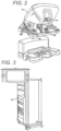
- FIG. 3 is a perspective view of the Electronics Cart 24.
- the Electronics Cart 24 can be coupled with the endoscope 28 and can include a processor to process captured images for subsequent display, such as to a Surgeon on the Surgeon's Console, or on another suitable display located locally and/or remotely.
- the Electronics Cart 24 can process the captured images to present the Surgeon with coordinated stereo images of the surgical site.
- Such coordination can include alignment between the opposing images and can include adjusting the stereo working distance of the stereoscopic endoscope.
- image processing can include the use of previously determined camera calibration parameters to compensate for imaging errors of the image capture device, such as optical aberrations.
- FIG. 4 diagrammatically illustrates a tele-surgical system 50 (such as N41RS system 10 of FIG. 1 ).
- a Surgeon's Console 52 (such as Surgeon's Console 16 in FIG.1 ) can be used by a Surgeon to control a Patient Side Cart (Surgical Robot) 54 (such as Patent Side Cart 22 in FIG. 1 ) during a minimally invasive procedure.
- the Patient Side Cart 54 can use an imaging device, such as a stereoscopic endoscope, to capture images of the procedure site and output the captured images to an Electronics Cart 56 (such as the Electronics Cart 24 in FIG. 1 ).
- the Electronics Cart 56 can process the captured images in a variety of ways prior to any subsequent display.
- the Electronics Cart 56 can overlay the captured images with a virtual control interface prior to displaying the combined images to the Surgeon via the Surgeon's Console 52.
- the Patient Side Cart 54 can output the captured images for processing outside the Electronics Cart 56.
- the Patient Side Cart 54 can output the captured images to a processor 58, which can be used to process the captured images.
- the images can also be processed by a combination the Electronics Cart 56 and the processor 58, which can be coupled together to process the captured images jointly, sequentially, and/or combinations thereof.
- One or more separate displays 60 can also be coupled with the processor 58 and/or the Electronics Cart 56 for local and/or remote display of images, such as images of the procedure site, or other related images.
- Processor 58 will typically include a combination of hardware and software, with the software comprising tangible media embodying computer readable code instructions for performing the method steps of the control functionally described herein.
- the hardware typically includes one or more data processing boards, which may be co-located but will often have components distributed among the manipulator structures described herein.
- the software will often comprise a non-volatile media, and could also comprise a monolithic code but will more typically comprise a number of subroutines, optionally running in any of a wide variety of distributed data processing architectures.
- FIGS. 5A and 5B show a Patient Side Cart 22 and a surgical tool 62, respectively,
- the surgical tool 62 is an example of the surgical tools 26.
- the Patient Side Cart 22 shown provides for the manipulation of three surgical tools 26 and an imaging device 28, such as a stereoscopic endoscope used for the capture of images of the site of the procedure. Manipulation is provided by manipulator mechanisms having a number of joints.
- the imaging device 28 and the surgical tools 26 can be positioned and manipulated through incisions in the patient so that a kinematic remote center is maintained at the incision to minimize the size of the incision.
- Images of the surgical site can include images of the distal ends of the surgical tools 26 when they are positioned within the field-of-view of the imaging device 28.
- Surgical tools 26 are inserted into the patient by inserting a tubular cannula 64 through a minimally invasive access aperture such as an incision, natural orifice, percutaneous penetration, or the like.
- Cannula 64 is mounted to the manipulator arm and the shaft of surgical tool 26 passes through the lumen of the cannula.
- the manipulator arm may transmit signals indicating that the cannula has been mounted thereon.
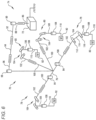
- FIG. 6 is a perspective schematic representation of a tele-surgical system 70, in accordance with many embodiments.
- the surgery system 70 includes a mounting base 72, a support linkage 74, an orienting platform 76, a plurality of outer set-up linkages 78 (two shown), a plurality of inner set-up linkages 80 (two shown), and a plurality of surgical instrument manipulators 82.
- Each of the manipulators 82 is operable to selectively articulate a surgical instrument mounted to the manipulator 82 and insertable into a patient along an insertion axis.
- Each of the manipulators 82 is attached to and supported by one of the set-up linkages 78, 80.
- Each of the outer set-up linkages 78 is rotationally coupled to and supported by the orienting platform 76 by a first set-up linkage joint 84.
- Each of the inner set-up linkages 80 is fixedly attached to and supported by the orienting platform 76.
- the orienting platform 76 is rotationally coupled to and supported by the support linkage 74.
- the support linkage 74 is fixedly attached to and supported by the mounting base 72.
- the mounting base 72 is movable and floor supported, thereby enabling selective repositioning of the overall surgery system 70, for example, within an operating room.
- the mounting base 72 can include a steerable wheel assembly and/or any other suitable support features that provide for both selective repositioning as well as selectively preventing movement of the mounting base 72 from a selected position.
- the mounting base 72 can also have other suitable configurations, for example, a ceiling mount, fixed floor/pedestal mount, a wall mount, or an interface configured for being supported by any other suitable mounting surface.
- the support linkage 74 is operable to selectively position and/or orient the orienting platform 76 relative to the mounting base 72.
- the support linkage 74 includes a column base 86, a translatable column member 88, a shoulder joint 90, a boom base member 92, a boom first stage member 94, a boom second stage member 96, and a wrist joint 98.
- the column base 86 is fixedly attached to the mounting base 72.
- the translatable column member 88 is slideably coupled to the column base 86 for translation relative to column base 86. In many embodiments, the translatable column member 88 translates relative to the column base 86 along a vertically oriented axis.
- the boom base member 92 is rotationally coupled to the translatable column member 88 by the shoulder joint 90.
- the shoulder joint 90 is operable to selectively orient the boom base member 92 in a horizontal plane relative to the translatable column member 88, which has a fixed angular orientation relative to the column base 86 and the mounting base 72.
- the boom first stage member 94 is selectively translatable relative to the boom base member 92 in a horizontal direction, which in many embodiments is aligned with both the boom base member 92 and the boom first stage member 94.
- the boom second stage member 96 is likewise selectively translatable relative to the boom first stage member 94 in a horizontal direction, which in many embodiments is aligned with the boom first stage member 94 and the boom second stage member 96.
- the support linkage 74 is operable to selectively set the distance between the shoulder joint 90 and the distal end of the boom second stage member 96.
- the wrist joint 98 rotationally couples the distal end of the boom second stage member 96 to the orienting platform 76.
- the wrist joint 98 is operable to selectively set the angular orientation of the orienting platform 76 relative to the mounting base 72.
- Each of the set-up linkages 78, 80 is operable to selectively position and/or orient the associated manipulator 82 relative to the orienting platform 76.
- Each of the set-up linkages 78, 80 includes a set-up linkage base link 100, a set-up linkage extension link 102, a set-up linkage parallelogram linkage portion 104, a set-up linkage vertical link 106, a second set-up linkage joint 108, and a manipulator support link 110.
- each of the set-up linkage base links 100 of the outer set-up linkages 78 can be selectively oriented relative to the orienting platform 76 via the operation of the a first set-up linkage joint 84.
- each of the set-up linkage base links 100 of the inner set-up linkages 80 is fixedly attached to the orienting platform 76.
- Each of the inner set-up linkages 80 can also be rotationally attached to the orienting platform 76 similar to the outer set-up linkages via an additional first set-up linkage joints 84.
- Each of the set-up linkage extension links 102 is translatable relative to the associated set-up linkage base link 100 in a horizontal direction, which in many embodiments is aligned with the associated set-up linkage base link and the set-up linkage extension link 102,
- Each of the set-up linkage parallelogram linkage portions 104 configured and operable to selectively translate the set-up linkage vertical link 106 in a vertical direction while keeping the set-up linkage vertical link 106 vertically oriented.
- each of the set-up linkage parallelogram linkage portions 104 includes a first parallelogram joint 112, a coupling link 114, and a second parallelogram 116.
- the first parallelogram joint 112 rotationally couples the coupling link 114 to the set-up linkage extension link 102.
- the second parallelogram joint 116 rotationally couples the set-up linkage vertical link 106 to the coupling link 114.
- the first parallelogram joint 112 is rotationally tied to the second parallelogram joint 116 such that rotation of the coupling link 114 relative to the set-up linkage extension link 102 is matched by a counteracting rotation of the set-up linkage vertical link 106 relative to the coupling link 114 so as to maintain the set-up linkage vertical link 106 vertically oriented while the set-up linkage vertical link 106 is selectively translated vertically.
- the second set-up linkage joint 108 is operable to selectively orient the manipulator support link 110 relative to the set-up linkage vertical link 106, thereby selectively orienting the associated attached manipulator 82 relative to the set-up linkage vertical link 106.
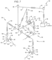
- FIG. 7 is a perspective schematic representation of a tele-surgical system 120, in accordance with many embodiments.
- the surgery system 120 includes the mounting base 72, a support linkage 122, an orienting platform 124, a plurality of set-up linkages 126 (four shown), and a plurality of the surgical instrument manipulators 82.
- Each of the manipulators 82 is operable to selectively articulate a surgical instrument mounted to the manipulator 82 and insertable into a patient along an insertion axis.
- Each of the manipulators 82 is attached to and supported by one of the set-up linkages 126.
- Each of the set-up linkages 126 is rotationally coupled to and supported by the orienting platform 124 by the first set-up linkage joint 84.
- the orienting platform 124 is rotationally coupled to and supported by the support linkage 122.
- the support linkage 122 is fixedly attached to and supported by the mounting base 72.
- the support linkage 122 is operable to selectively position and/or orient the orienting platform 124 relative to the mounting base 72.
- the support linkage 122 includes the column base 86, the translatable column member 88, the shoulder joint 90, the boom base member 92, the boom first stage member 94, and the wrist joint 98.
- the support linkage 122 is operable to selectively set the distance between the shoulder joint 90 and the distal end of the boom first stage member 94.
- the wrist joint 98 rotationally couples the distal end of the boom first stage member 94 to the orienting platform 124.
- the wrist joint 98 is operable to selectively set the angular orientation of the orienting platform 124 relative to the mounting base 72.
- Each of the set-up linkages 126 is operable to selectively position and/or orient the associated manipulator 82 relative to the orienting platform 124.
- Each of the set-up linkages 126 includes the set-up linkage base link 100, the set-up linkage extension link 102, the set-up linkage vertical link 106, the second set-up linkage joint 108, a tornado mechanism support link 128, and a tornado mechanism 130.
- Each of the set-up linkage base links 100 of the set-up linkages 126 can be selectively oriented relative to the orienting platform 124 via the operation of the associated first set-up linkage joint 84.
- Each of the set-up linkage vertical links 106 is selectively translatable in a vertical direction relative to the associated set-up linkage extension link 102.
- the second set-up linkage joint 108 is operable to selectively orient the tornado mechanism support link 128 relative to the set-up linkage vertical link 106
- Each of the tornado mechanisms 130 includes a tornado joint 132, a coupling link 134, and a manipulator support 136.
- the coupling link 134 fixedly couples the manipulator support 136 to the tornado joint 132.
- the tornado joint 130 is operable to rotate the manipulator support 136 relative to the tornado mechanism support link 128 around a tornado axis 136.
- the tornado mechanism 128 is configured to position and orient the manipulator support 134 such that the remote center of manipulation (RC) of the manipulator 82 is intersected by the tornado axis 136. Accordingly, operation of the tornado joint 132 can be used to reorient the associated manipulator 82 relative to the patient without moving the associated remote center of manipulation (RC) relative to the patient.
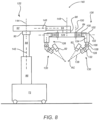
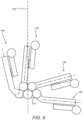
- FIG. 8 is a simplified representation of a tele-surgical system 140, in accordance with many embodiments, in conformance with the schematic representation of the tele-surgical system 120 of FIG. 7 . Because the surgery system 140 conforms to the tele-surgical system 120 of FIG. 7 , the same reference numbers are used for analogous components and the corresponding description of the analogous components set forth above is applicable to the surgery system 140 and is omitted here to avoid repetition.
- the support linkage 122 is configured to selectively position and orient the orienting platform 124 relative to the mounting base 72 via relative movement between links of the support linkage 122 along multiple set-up structure axes.
- the translatable column member 88 is selectively repositionable relative to the column base 86 along a first set-up structure (SUS) axis 142, which is vertically oriented in many embodiments.
- the shoulder joint 90 is operable to selectively orient the boom base member 92 relative to the translatable column member 88 around a second SUS axis 144, which is vertically oriented in many embodiments.
- the boom first stage member 94 is selectively repositionable relative to the boom base member 92 along a third SUS axis 146, which is horizontally oriented in many embodiments.
- the wrist joint 98 is operable to selectively orient the orienting platform 124 relative to the boom first stage member 94 around a fourth SUS axis 148, which is vertically oriented in many embodiments.
- Each of the set-up linkages 126 is configured to selectively position and orient the associated manipulator 82 relative to the orienting platform 124 via relative movement between links of the set-up linkage 126 along multiple set-up joint (SUJ) axes.
- Each of the first set-up linkage joint 84 is operable to selectively orient the associated set-up linkage base link 100 relative to the orienting platform 124 around a first SUJ axis 150, which in many embodiments is vertically oriented.
- Each of the set-up linkage extension links 102 can be selectively repositioned relative to the associated set-up linkage base link 10 along a second SUJ axis 152, which is horizontally oriented in many embodiments.
- Each of the set-up linkage vertical links 106 can be selectively repositioned relative to the associated set-up linkage extension link 102 along a third SUJ axis 154, which is vertically oriented in many embodiments.
- Each of the second set-up linkage joints 108 is operable to selectively orient the tornado mechanism support link 128 relative to the set-up linkage vertical link 106 around the third SUJ axis 154.
- Each of the tornado joints 132 is operable to rotate the associated manipulator 82 around the associated tornado axis 138.
- FIG. 9 illustrates rotational orientation limits of the set-up linkages 126 relative to the orienting platform 124, in accordance with many embodiments.
- Each of the set-up linkages 126 is shown in a clockwise limit orientation relative to the orienting platform 124.
- a corresponding counter-clockwise limit orientation is represented by a mirror image of FIG. 9 relative to a vertically-oriented mirror plane.
- each of the two inner set-up linkages 126 can be oriented from 5 degrees from a vertical reference 156 in one direction to 75 degrees from the vertical reference 156 in the opposite direction.
- each of the two outer set-up linkages can be oriented from 15 degrees to 95 degrees from the vertical reference 1 56 in a corresponding direction.
- a surgical assistant, surgeon, technical support, or other user In use, it will often be desirable for a surgical assistant, surgeon, technical support, or other user to configure some or all of the linkages of tele-surgical system 140 for surgery, including the set-up structure linkage, the set-up joints, and/or each of the manipulators. Included among the task in configuring these linkages will be positioning the orienting platform 124 relative to first stage member 94 about vertical fourth SUS axis 148 of wrist joint 98.
- a joint drive motor 121 and/or brake system 123 is coupled to wrist joint 98, with one exemplary embodiment including both a drive 121 and brake 123. Additionally, a joint sensor system will typically sense an angular configuration or position of wrist joint 98.
- An exemplary user interface, system, and method for manually configuring the system for use will be described herein with reference to manual articulation of orienting platform 124 by articulation of wrist joint 98 about fourth SUS axis 148, as schematically illustrated by arrow 127.
- alternative embodiments may be employed to articulate one or more alternative joints of the overall kinematic system, including one or more alternative joints of the set-up structure, one or more of the set-up joints, or one or more of the joints of the manipulators linkages.
- Use of the exemplary embodiment for articulating the motorized wrist joint embodiments may allow a user to efficiently position manipulators 82.
- the manual articulation of wrist joint 98 as described herein can improve speed and ease of use while manually docking manipulators 82 to their associated cannulas 64, as shown in FIG. SB.
- FIG. 10 shows a center of gravity diagram associated with a rotational limit of a support linkage for a tele-surgical system 160, in accordance with many embodiments.
- a shoulder joint of the support linkage 164 can be configured to limit rotation of the support structure 164 around a set-up structure (SDS) shoulder-joint axis 166 to prevent exceeding a predetermined stability limit of the mounting base.
- SDS set-up structure
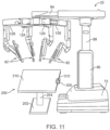
- FIG. 11 illustrates an overview of an example system including the Patient Side Cart 22 having multiple manipulator arms 82 supported by associated set-up structure linkages 126 under which a surgical table 200 is disposed.
- the surgical table 200 is a separate structure from the Patient. Side Cart such that the surgical table is separately positionable, and often independently positionable, from the Patient Side Cart. It is understood however, that in certain other aspects, the registration methods described herein allow for a separately positionable surgical table to be controlled in coordination with calculated movements of the manipulator such that the surgical table remains separately positionable but may no longer be considered independently positionable since such movements would be coordinated by the system.
- surgical table 200 includes a surgical table patient support surface 210, supported by a support column 204 attached to a support base 202.
- the system further includes a registration feature 300 that allows the system to register the surgical table relative the Patient Side Cart such that a spatial relationship between the manipulators of the Patient Side Cart and the surgical table patient surface 210 can be determined and may be utilized in calculated manipulator movements or commanded surgical table movements. While the registration feature 300 may encompass various different structures, described and shown in subsequent figures, FIG. 11 illustrates a registration feature that includes a table-mounted registration device 310, described in further detail below.
- FIG. 12 illustrates an example surgical table 200 for use with a surgical manipulator system.
- the surgical table 200 may include one or more joints (not shown) that when actuated move the surgical table top to a desired position and/or orientation.
- the one or more joints may include driven joints, manually articulated joints, or a combination thereof.
- Such joints may include translatable joints, such as hydraulics, as well as rotatable and pivotal joints, such as any of those described herein.
- the one or more joints may be adjusted by a patient side-assistant or anesthesiologist, as needed, or may be configured to be adjusted by a more remote user, such as a physician from the Surgeon Console, or by the system according to an autonomous algorithm or according to one or more calculated movements, such as a compensating movement for physiological movements, such as patient breathing and the like.
- the surgical table 200 includes the surgical table patient support surface 210 supported by a support column 204 extending vertically from a support base 202.
- the surgical table 200 is positionable along at least one degree of freedom, preferably along multiple degrees of freedom, and even more preferably along six degrees of freedom.
- the example surgical table 200 can be translated in three different directions orthogonal to one another, along the x-axis, the y-axis and vertically along the z-axis, and can be pivoted about axis 214 extending along the length of the patient support surface 210, pivoted about axis 216 extending along the width of the patient support surface 210 and pivoted about axis 212 extending vertically.
- the example surgical table 200 is positionable along six degrees of freedom. These various positions and/or orientations of the patient support surface 210 allowed by these six degrees of freedom may be utilized during initial set-up to achieve a desired position, orientation or inclination of the patent or may be utilized during a procedure as needed to reposition the patient for any reason.
- the pivotal movements need not be centered along those particular axes shown, such that a table may provide such pivotal movements along various other axes in the same directions, thereby allowing the surgical table top to provide pivotal movements about various locations on or off the table top.
- the surgical table is configured to provide such movements about an isocenter at or near a cannula through which an instrument is inserted within a minimally invasive aperture.
- Registration may be performed using various different approaches, for example approaches that include contact with the surgical table in accordance with the claimed invention and approaches that do not require direct physical contact with the surgical table. not covered by the claimed invention. While each of these approaches may offer certain advantages for particular systems or applications, it is appreciated that any aspect of these approaches may be modified and/or combined such that a method may include aspects of contact-based approaches in addition to non-contact based approaches. Examples of these approaches are described in further detail below.
- registration is performed by facilitated contact between the Patient Side Cart and the surgical table.
- Methods of registration may include contacting the surgical table at one or more locations with a component of the Patient Side Cart and determining a position and/or orientation of the surgical table relative the Patient Side Cart. This may be accomplished by determining the position and/or orientation of the surgical table relative to a frame of reference of the Patient Side Cart or a common frame of reference having a known or determinable relationship to both the Patient Side Cart and the surgical table.
- contact with the surgical table may include contacting multiple locations with one or more location components associated with the Patient Side Cart so that the position and/or orientation of the surgical table can be determined by a determined state of the location component.
- a manipulator arm may function as the location component for registration purposes by using one or more joint sensors of the manipulator to determine a location of the contact point of the surgical table relative to the Patient Side Cart or corresponding frame of reference. If a geometry of the surgical table is known, the position and/or orientation of the surgical table can be determined with fewer points of contact, for example three points of contact. However, if a geometry of the surgical table is unknown, additional points of contact may be used to determine the bounds of the table, for example at least four contact locations (e.g.
- contact locations utilized may differ according to the table geometry.
- certain surgical tables may include multiple planes that are movable relative each other (e.g. a dentist's chair) such that additional contact locations may be utilized to determine a position or orientation of the chair.
- sensed joint states of a chair having multiple planes may be used in conjunction with any of the registration features described herein to determine a position and/or orientation of the chair relative to the manipulator assembly.
- contact with the surgical table includes contacting a single location with a location component and determining a position and/or orientation along one or more degrees of freedom of the surgical table by constraining movement of the location component along corresponding degrees of freedom.
- the registration feature 300 is a table-mounted registration device 310 to which a distal portion of a manipulator 82 can be releasably coupled.
- movement of the manipulator 82 is constrained along multiple degrees of freedom such that the position and/or orientation of the surgical table in corresponding degrees of freedom of the surgical table can be determined from joint sensors of the manipulator.
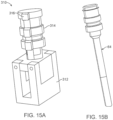
- FIGS. 15A illustrates an example table-mounted registration device 310, in accordance with aspects of the claimed invention, having a table-mount portion 312 and a cannula mount knob 314 configured for releasably coupling with a cannula mount of a distal portion of the manipulator 82.
- the cannula mount knob 314 may be a solid element cylindrical element shaped according to the dimensions of a cannula 64 (shown in FIG. 15B ), for which the cannula mount of the manipulator 82 is designed to be attached.
- the knob is configured to be received within the cannula mount clamp described in U.S. Patent No. 8,182,469 .
- the cannula mount knob 314 includes a table-mount portion 312 that mounts to a side-bar of the surgical table and an orientation key 316 that protrudes radially outward from the knob 314 so as to constrain rotational movement of the cannula mount so that each of the six degrees of freedom of the surgical table can be determined from the joint state sensors of the manipulator when attached to the table through the registration device. While this feature is described within the context of the cannula mount of the manipulator, it is appreciated that the registration device 310 may be configured to attach to any portion of any manipulator, of the Patient Side Cart or a component (even a temporarily attached component) extending therebetween so as to allow determination of a spatial relationship between the surgical table and the Patient Side Cart and associated manipulators.
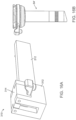
- FIGS. 16A illustrates another example table-mounted registration device 310 having a table-mount portion 312 and a cannula mount element 314' corresponding to another type of cannula 64.'
- the approach described in FIG. 15A can be used in various types of manipulator systems by fabricating a table-mounted registration device to resemble a cannula used in a particular manipulator system to allow registration using existing features of the system.
- FIG. 16A also further details the means by which the table-mounted device 310 attached to the table. While the table-mounted registration device can be attached to the surgical table by various means, it is particularly useful if such a device can be attached without requiring modification of or installation of additional structures to the table.
- the registration device 310 may include a side-bar mount 312 that mounts to the side-bar by engaging the side-bar as well as the support by which the side-bar mounts to the table.
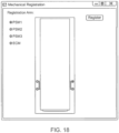
- a side-bar 212 typically mounts to the surgical table by two such lateral supports near opposite ends of the side bar such that in a surgical table having side-bars 212 on both sides, there would be four such locations at which such a registration device 310 could be mounted (see for example FIG. 18 ).
- the position and/or orientation of the table can be more accurately determined using a known or estimated geometry of the table. For example, as shown in FIG. 18 , if there are four possible locations on the table at which the registration device 310 can be attached, then the position and /or orientation of the table can be accurately determined, typically within less than one centimeter or less, using a known geometry of the surgical table and the joint state sensor data from the manipulator attached to the registration device 310 mounted to the table at known location.
- the system may be configured such that a user inputs the location of the table to which the registration device is attached as well as which manipulator is coupled with the registration device (for example, by use of a dialog box prompt shown in FIG. 18 ).
- the system may automatically detect, such as by use of a mechanical means, RFID, sonar or optical sensing means, at which location of the table the registration device 310 is attached as well as which manipulator is coupled with the registration device 310.
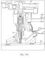
- FIGS. 17A-17D illustrate additional views of the table-mounted registration device 310 similar to that in FIG. 15A , which is mounted to a side-bar 212 of the surgical table and to which the cannula mount of a manipulator is mounted to facilitate registration between the surgical table and the Patient Side Cart.
- spring-loaded linear encoders can be mounted on the Patient Side Cart. As illustrated in FIG. 20 , each of the spring-loaded linear encoders 330 can be stretched and attached to hooks on the side of the table so as to extend between the surgical table and the Patient Side Cart, or an associated component. In one aspect, at least three linear encoders are used so that readings from the linear encoders can be triangulated to determine the position and pose of the surgical table relative Patient Side Cart and surgical table. It is further appreciated that such encoders can also be used extending between the surgical table and an external frame of reference, such as the floor of the surgical room, to allow registration through a common external frame of reference. This approach can be used initially within a pre-docking registration or such encoders can remain attached so as to allow determination of the position and/or orientation of the surgical table during the procedure and maintain registration throughout the procedure without otherwise requiring use of one of the manipulators.
- the system may utilize a flexible arm equipped with shape sensors.
- the shape sensor is a hose-like object hanging on the side of the Patient Side Cart which has a tip that can be locked to the side of the table.
- the locking mechanism has sensors which detect connection/disconnection.
- Shape sensors e.g., optical shape sensing fibers
- Shape information can be used to calculate the relative pose of the Patient Side Cart with respect to the table.
- the shape sensor such as a cable shape sensor, optical fiber, flex or position orientation sensing member, can be attached or locked to a side of the table, such that the position and/or orientation can readily be determined by the system based on input from the shape sensor.
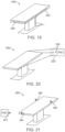
- FIG. 19 shows a shape cable sensor 320 extending attached to two sides of the surgical table so as to allow for determination of a position and pose of the surgical table from a sensed output from the shape cable.
- This is advantageous as the shape sensor allows the position and/or orientation to be dynamically sensed during a procedure such that registration between the manipulators and surgical table is substantially continuous during a procedure.
- the methods of registration described herein may further include any of the aspects described in U.S. Application No. 7,930,065 filed July 20, 2006 , entitled “Robotic Surgery System Including Position Sensors Using Fiber Bragg Gratings,”.
- one or more shape sensor cords can be attached to one or more particular locations of the surgical table to allow the system to determine a position and/or orientation of the table.
- shape sensor cables may be incorporated into the cables by which the Patient Side Cart and the surgical table are powered such that the Patient Side Cart can be registered to one another through an external frame of reference, such as the surgical operating room to which the cords are attached.
- the system may utilize such a shape sensor cord extending directly between the Patient Side Cart and the surgical table, which can be used for registration purposes, in addition to various other purposes.
- various other non-contact means may be used by which to determine a position and/or orientation of the surgical table relative the Patient Side Cart.
- Such means may include any of optical or radiation sensing means, sonar, laser range sensors, or any other suitable means.
- such sensing means can be attached to the Patient Side Cart and configured to sense one or more points on the surgical table (e.g. RFID tags, identifiable optical or laser markers) such that the position and/or orientation of the table relative the Patient Side Cart can be determined before and/or during the procedure.
- RFID tags e.g. RFID tags, identifiable optical or laser markers
- This approach particularly when using RFID tags, may be on one or both of the surgical table and the Patient Side Cart to determine absolute locations or relative locations between the surgical table and the Patient Side Cart so as to allow for registration therebetween. An example of this approach is illustrated in FIG.
- FIG. 21 which show an RFID sensor 341 attached to the Patient Side Cart (not shown) that can sense a position of each of three RFID tags 340 attached to the table at various locations. By triangulating the signals from each of the RFID tags, the position and pose of the surgical table can be determined.
- this approach can also be used to allow registration through a common external frame of reference, such as by sensing the RFID location from an external reference frame, such as a known location in the surgical room.
- the methods described herein may perform registration using absolute location or relative location for real-time location using point-to-point distance determination between multiple RFID tags or various other real-time location approaches.
- methods of registration include a pre-docking registration.
- a manipulator arm Prior to docking the surgical manipulators to a patient on the patient support surface of the surgical table, a manipulator arm is docked to a table-side mounted registration device 310 (such as in FIG. 15A or FIG. 16A ).
- a table-side mounted registration device 310 such as in FIG. 15A or FIG. 16A .
- PSM Patient Side Manipulator
- SUJs Set-up Joints
- the registration device 310 is configured such that it can only be attached to the table in a unique way, that is at one or more particular locations of the table at a particular alignment/orientation relative to the table (e.g. such as at one of four locations where the side rails connect to the table top). Therefore the pose of the gadget with respect to the table can readily be determined, such as from CAD models of the table geometry or from a calibration of the table top using one or more sensors or an external tracker.
- the surgical operating table can be motorized and encoders can be used with the actuation joints of the table (q table ) to provide its position and orientation.
- pre-docking registration between the Patient Side Cart and the surgical operating table would be performed once before a procedure, after which generally the Patient Side Cart (PCS) would not be moved since this may necessitate another registration during the procedure in which the manipulators would be undocked, another registration performed and then re-docking the manipulators with the patient.
- PCS Patient Side Cart
- the manipulator used for registration may remain docked during the entire procedure such that registration would be substantially continuous allowing movement of the surgical table during a procedure without requiring performing of additional registration steps during the procedure.
- One drawback with this approach is that the use of one manipulator may be lost such that this approach may not be suitable for a procedure utilizing each of the manipulators.
- any of the alternative technologies or approaches described herein may be utilized to perform registration in accordance with aspects of the invention.
- one possible scenario is to leave one of the manipulator arms connected to the registration gadget during the operation. In such cases, it is possible to detect any motion of the Patient Side Cart and generate alarms if the Patient Side Cart has moved during the operation. In one aspect, this can be done, by (a) releasing Setup Joint (SUJ) brakes and monitoring their encoder values or (b) monitoring the torque on Set-Up Joints and manipulator joints or a combination thereof.
- SAJ Setup Joint
- a mobile surgical manipulator when a mobile surgical manipulator is docked to the patient, generally, it is not feasible to move the table. If table motion is needed for any reason (including reorienting the patient), generally, a user must undock the manipulators from the patient, move the table and then re-dock the manipulators with the patient.
- the system By using a manipulator arm that remains attached to the table through a registration device mounted on the surgical table during the procedure, the system creates a closed kinematic chain between the robot and the table. This can be used to perform a real-time registration of the surgical table and the manipulator assembly. Therefore, if the surgical table is moving, any manipulator arms docked with the patient can be moved accordingly and there is no need for undocking the robot.
- a separately positionable surgical table can be incorporated into a surgical system having a manipulator assembly such that movements between the surgical table and the manipulator assembly can be coordinated such that further advantageous features may be realized.
Landscapes
- Health & Medical Sciences (AREA)
- Engineering & Computer Science (AREA)
- Life Sciences & Earth Sciences (AREA)
- Surgery (AREA)
- Biomedical Technology (AREA)
- Public Health (AREA)
- General Health & Medical Sciences (AREA)
- Medical Informatics (AREA)
- Robotics (AREA)
- Animal Behavior & Ethology (AREA)
- Veterinary Medicine (AREA)
- Nuclear Medicine, Radiotherapy & Molecular Imaging (AREA)
- Heart & Thoracic Surgery (AREA)
- Molecular Biology (AREA)
- Epidemiology (AREA)
- Primary Health Care (AREA)
- General Business, Economics & Management (AREA)
- Business, Economics & Management (AREA)
- Physics & Mathematics (AREA)
- Pathology (AREA)
- Oral & Maxillofacial Surgery (AREA)
- Electromagnetism (AREA)
- Manipulator (AREA)
- Radiology & Medical Imaging (AREA)
Applications Claiming Priority (2)
| Application Number | Priority Date | Filing Date | Title |
|---|---|---|---|
| US201461954538P | 2014-03-17 | 2014-03-17 | |
| PCT/US2015/020891 WO2015142798A1 (en) | 2014-03-17 | 2015-03-17 | Methods and devices for tele-surgical table registration |
Publications (3)
| Publication Number | Publication Date |
|---|---|
| EP3119337A1 EP3119337A1 (en) | 2017-01-25 |
| EP3119337A4 EP3119337A4 (en) | 2017-12-06 |
| EP3119337B1 true EP3119337B1 (en) | 2024-05-15 |
Family
ID=54145194
Family Applications (1)
| Application Number | Title | Priority Date | Filing Date |
|---|---|---|---|
| EP15765677.8A Active EP3119337B1 (en) | 2014-03-17 | 2015-03-17 | Methods and devices for tele-surgical table registration |
Country Status (6)
Families Citing this family (199)
| Publication number | Priority date | Publication date | Assignee | Title |
|---|---|---|---|---|
| US11871901B2 (en) | 2012-05-20 | 2024-01-16 | Cilag Gmbh International | Method for situational awareness for surgical network or surgical network connected device capable of adjusting function based on a sensed situation or usage |
| US20140005640A1 (en) | 2012-06-28 | 2014-01-02 | Ethicon Endo-Surgery, Inc. | Surgical end effector jaw and electrode configurations |
| JP6660302B2 (ja) | 2014-03-17 | 2020-03-11 | インテュイティブ サージカル オペレーションズ, インコーポレイテッド | 基準目標に合わせるシステム及び方法 |
| EP3119337B1 (en) | 2014-03-17 | 2024-05-15 | Intuitive Surgical Operations, Inc. | Methods and devices for tele-surgical table registration |
| WO2016069650A1 (en) | 2014-10-27 | 2016-05-06 | Intuitive Surgical Operations, Inc. | System and method for integrated surgical table icons |
| EP4082466B1 (en) | 2014-10-27 | 2025-07-30 | Intuitive Surgical Operations, Inc. | System for instrument disturbance compensation |
| CN107072864B (zh) | 2014-10-27 | 2019-06-14 | 直观外科手术操作公司 | 用于配准到手术台的系统及方法 |
| JP6644061B2 (ja) | 2014-10-27 | 2020-02-12 | インテュイティブ サージカル オペレーションズ, インコーポレイテッド | 能動的ブレーキ解放制御装置を備える医療デバイス |
| KR102799097B1 (ko) | 2014-10-27 | 2025-04-23 | 인튜어티브 서지컬 오퍼레이션즈 인코포레이티드 | 반응 운동 동안 제어점을 감시하기 위한 시스템 및 방법 |
| EP3741345A1 (en) | 2014-10-27 | 2020-11-25 | Intuitive Surgical Operations, Inc. | System for integrated surgical table motion |
| KR102545930B1 (ko) | 2014-10-27 | 2023-06-22 | 인튜어티브 서지컬 오퍼레이션즈 인코포레이티드 | 통합 수술 테이블을 위한 시스템 및 방법 |
| US10603135B2 (en) * | 2014-10-30 | 2020-03-31 | Intuitive Surgical Operations, Inc. | System and method for an articulated arm based tool guide |
| WO2016069998A1 (en) | 2014-10-30 | 2016-05-06 | Intuitive Surgical Operations, Inc. | System and method for articulated arm stabilization |
| US11504192B2 (en) | 2014-10-30 | 2022-11-22 | Cilag Gmbh International | Method of hub communication with surgical instrument systems |
| DE102015113110B4 (de) * | 2015-08-10 | 2019-03-14 | MAQUET GmbH | Ansteuervorrichtung mindestens einer Antriebseinrichtung eines Operationstisches und Verfahren zum Ansteuern |
| EP3337419B1 (en) * | 2015-08-19 | 2020-08-12 | Brainlab AG | Reference array holder |
| EP3200719B1 (en) | 2015-11-02 | 2019-05-22 | Brainlab AG | Determining a configuration of a medical robotic arm |
| GB201521814D0 (en) | 2015-12-10 | 2016-01-27 | Cambridge Medical Robotics Ltd | Arm location |
| CN110602976B (zh) * | 2017-04-07 | 2022-11-15 | 奥瑞斯健康公司 | 患者导引器对准 |
| KR102422733B1 (ko) * | 2017-05-12 | 2022-07-18 | 사이버 서저리, 에스. 엘. | 정형외과 수술을 위한 수술 로봇 |
| US10792119B2 (en) * | 2017-05-22 | 2020-10-06 | Ethicon Llc | Robotic arm cart and uses therefor |
| US10856948B2 (en) * | 2017-05-31 | 2020-12-08 | Verb Surgical Inc. | Cart for robotic arms and method and apparatus for registering cart to surgical table |
| US10485623B2 (en) * | 2017-06-01 | 2019-11-26 | Verb Surgical Inc. | Robotic arm cart with fine position adjustment features and uses therefor |
| US11052930B2 (en) | 2017-06-16 | 2021-07-06 | Verb Surgical Inc. | Robotic arm cart having locking swivel joints and other position adjustment features and uses therefor |
| US10913145B2 (en) * | 2017-06-20 | 2021-02-09 | Verb Surgical Inc. | Cart for robotic arms and method and apparatus for cartridge or magazine loading of arms |
| EP3644889A4 (en) | 2017-06-28 | 2021-04-07 | Intuitive Surgical Operations, Inc. | SYSTEMS AND METHODS FOR PROJECTING AN ENDOSCOPIC IMAGE ON A THREE-DIMENSIONAL VOLUME |
| US12011236B2 (en) | 2017-08-08 | 2024-06-18 | Intuitive Surgical Operations, Inc. | Systems and methods for rendering alerts in a display of a teleoperational system |
| DE102017118126A1 (de) | 2017-08-09 | 2019-02-14 | avateramedical GmBH | Robotisches Operationssystem |
| US11291510B2 (en) | 2017-10-30 | 2022-04-05 | Cilag Gmbh International | Method of hub communication with surgical instrument systems |
| US11045197B2 (en) | 2017-10-30 | 2021-06-29 | Cilag Gmbh International | Clip applier comprising a movable clip magazine |
| US20190125476A1 (en) | 2017-10-30 | 2019-05-02 | Ethicon Llc | Surgical instrument systems comprising lockout mechanisms |
| US11911045B2 (en) | 2017-10-30 | 2024-02-27 | Cllag GmbH International | Method for operating a powered articulating multi-clip applier |
| US11510741B2 (en) | 2017-10-30 | 2022-11-29 | Cilag Gmbh International | Method for producing a surgical instrument comprising a smart electrical system |
| US11311342B2 (en) | 2017-10-30 | 2022-04-26 | Cilag Gmbh International | Method for communicating with surgical instrument systems |
| US11801098B2 (en) | 2017-10-30 | 2023-10-31 | Cilag Gmbh International | Method of hub communication with surgical instrument systems |
| US11229436B2 (en) | 2017-10-30 | 2022-01-25 | Cilag Gmbh International | Surgical system comprising a surgical tool and a surgical hub |
| US11317919B2 (en) | 2017-10-30 | 2022-05-03 | Cilag Gmbh International | Clip applier comprising a clip crimping system |
| US11564756B2 (en) | 2017-10-30 | 2023-01-31 | Cilag Gmbh International | Method of hub communication with surgical instrument systems |
| CN112315585B (zh) | 2017-12-27 | 2022-04-08 | 上海微创医疗机器人(集团)股份有限公司 | 手术机器人终端 |
| US11432885B2 (en) | 2017-12-28 | 2022-09-06 | Cilag Gmbh International | Sensing arrangements for robot-assisted surgical platforms |
| US12376855B2 (en) | 2017-12-28 | 2025-08-05 | Cilag Gmbh International | Safety systems for smart powered surgical stapling |
| US11419667B2 (en) | 2017-12-28 | 2022-08-23 | Cilag Gmbh International | Ultrasonic energy device which varies pressure applied by clamp arm to provide threshold control pressure at a cut progression location |
| US11559308B2 (en) | 2017-12-28 | 2023-01-24 | Cilag Gmbh International | Method for smart energy device infrastructure |
| US11100631B2 (en) | 2017-12-28 | 2021-08-24 | Cilag Gmbh International | Use of laser light and red-green-blue coloration to determine properties of back scattered light |
| US11389164B2 (en) | 2017-12-28 | 2022-07-19 | Cilag Gmbh International | Method of using reinforced flexible circuits with multiple sensors to optimize performance of radio frequency devices |
| US10892995B2 (en) | 2017-12-28 | 2021-01-12 | Ethicon Llc | Surgical network determination of prioritization of communication, interaction, or processing based on system or device needs |
| WO2019133143A1 (en) | 2017-12-28 | 2019-07-04 | Ethicon Llc | Surgical hub and modular device response adjustment based on situational awareness |
| US11166772B2 (en) | 2017-12-28 | 2021-11-09 | Cilag Gmbh International | Surgical hub coordination of control and communication of operating room devices |
| US11179208B2 (en) | 2017-12-28 | 2021-11-23 | Cilag Gmbh International | Cloud-based medical analytics for security and authentication trends and reactive measures |
| US11969216B2 (en) | 2017-12-28 | 2024-04-30 | Cilag Gmbh International | Surgical network recommendations from real time analysis of procedure variables against a baseline highlighting differences from the optimal solution |
| US11832840B2 (en) | 2017-12-28 | 2023-12-05 | Cilag Gmbh International | Surgical instrument having a flexible circuit |
| US11903601B2 (en) | 2017-12-28 | 2024-02-20 | Cilag Gmbh International | Surgical instrument comprising a plurality of drive systems |
| US11896443B2 (en) | 2017-12-28 | 2024-02-13 | Cilag Gmbh International | Control of a surgical system through a surgical barrier |
| US20190201042A1 (en) | 2017-12-28 | 2019-07-04 | Ethicon Llc | Determining the state of an ultrasonic electromechanical system according to frequency shift |
| US11844579B2 (en) | 2017-12-28 | 2023-12-19 | Cilag Gmbh International | Adjustments based on airborne particle properties |
| US11464559B2 (en) | 2017-12-28 | 2022-10-11 | Cilag Gmbh International | Estimating state of ultrasonic end effector and control system therefor |
| US11304699B2 (en) | 2017-12-28 | 2022-04-19 | Cilag Gmbh International | Method for adaptive control schemes for surgical network control and interaction |
| US11013563B2 (en) | 2017-12-28 | 2021-05-25 | Ethicon Llc | Drive arrangements for robot-assisted surgical platforms |
| US11160605B2 (en) | 2017-12-28 | 2021-11-02 | Cilag Gmbh International | Surgical evacuation sensing and motor control |
| US11376002B2 (en) | 2017-12-28 | 2022-07-05 | Cilag Gmbh International | Surgical instrument cartridge sensor assemblies |
| US11364075B2 (en) | 2017-12-28 | 2022-06-21 | Cilag Gmbh International | Radio frequency energy device for delivering combined electrical signals |
| US11273001B2 (en) | 2017-12-28 | 2022-03-15 | Cilag Gmbh International | Surgical hub and modular device response adjustment based on situational awareness |
| US11786251B2 (en) | 2017-12-28 | 2023-10-17 | Cilag Gmbh International | Method for adaptive control schemes for surgical network control and interaction |
| US11317937B2 (en) | 2018-03-08 | 2022-05-03 | Cilag Gmbh International | Determining the state of an ultrasonic end effector |
| US11284936B2 (en) | 2017-12-28 | 2022-03-29 | Cilag Gmbh International | Surgical instrument having a flexible electrode |
| US20190201112A1 (en) | 2017-12-28 | 2019-07-04 | Ethicon Llc | Computer implemented interactive surgical systems |
| US11529187B2 (en) | 2017-12-28 | 2022-12-20 | Cilag Gmbh International | Surgical evacuation sensor arrangements |
| US11308075B2 (en) | 2017-12-28 | 2022-04-19 | Cilag Gmbh International | Surgical network, instrument, and cloud responses based on validation of received dataset and authentication of its source and integrity |
| US11253315B2 (en) | 2017-12-28 | 2022-02-22 | Cilag Gmbh International | Increasing radio frequency to create pad-less monopolar loop |
| US11266468B2 (en) | 2017-12-28 | 2022-03-08 | Cilag Gmbh International | Cooperative utilization of data derived from secondary sources by intelligent surgical hubs |
| US11678881B2 (en) | 2017-12-28 | 2023-06-20 | Cilag Gmbh International | Spatial awareness of surgical hubs in operating rooms |
| US11540855B2 (en) | 2017-12-28 | 2023-01-03 | Cilag Gmbh International | Controlling activation of an ultrasonic surgical instrument according to the presence of tissue |
| US20190201090A1 (en) | 2017-12-28 | 2019-07-04 | Ethicon Llc | Capacitive coupled return path pad with separable array elements |
| US11234756B2 (en) | 2017-12-28 | 2022-02-01 | Cilag Gmbh International | Powered surgical tool with predefined adjustable control algorithm for controlling end effector parameter |
| US11291495B2 (en) | 2017-12-28 | 2022-04-05 | Cilag Gmbh International | Interruption of energy due to inadvertent capacitive coupling |
| US11998193B2 (en) | 2017-12-28 | 2024-06-04 | Cilag Gmbh International | Method for usage of the shroud as an aspect of sensing or controlling a powered surgical device, and a control algorithm to adjust its default operation |
| US12127729B2 (en) | 2017-12-28 | 2024-10-29 | Cilag Gmbh International | Method for smoke evacuation for surgical hub |
| US11786245B2 (en) | 2017-12-28 | 2023-10-17 | Cilag Gmbh International | Surgical systems with prioritized data transmission capabilities |
| US20190201142A1 (en) * | 2017-12-28 | 2019-07-04 | Ethicon Llc | Automatic tool adjustments for robot-assisted surgical platforms |
| US11410259B2 (en) | 2017-12-28 | 2022-08-09 | Cilag Gmbh International | Adaptive control program updates for surgical devices |
| US11633237B2 (en) | 2017-12-28 | 2023-04-25 | Cilag Gmbh International | Usage and technique analysis of surgeon / staff performance against a baseline to optimize device utilization and performance for both current and future procedures |
| US11304763B2 (en) | 2017-12-28 | 2022-04-19 | Cilag Gmbh International | Image capturing of the areas outside the abdomen to improve placement and control of a surgical device in use |
| US11571234B2 (en) | 2017-12-28 | 2023-02-07 | Cilag Gmbh International | Temperature control of ultrasonic end effector and control system therefor |
| US11056244B2 (en) | 2017-12-28 | 2021-07-06 | Cilag Gmbh International | Automated data scaling, alignment, and organizing based on predefined parameters within surgical networks |
| US11464535B2 (en) | 2017-12-28 | 2022-10-11 | Cilag Gmbh International | Detection of end effector emersion in liquid |
| US11278281B2 (en) | 2017-12-28 | 2022-03-22 | Cilag Gmbh International | Interactive surgical system |
| US10758310B2 (en) | 2017-12-28 | 2020-09-01 | Ethicon Llc | Wireless pairing of a surgical device with another device within a sterile surgical field based on the usage and situational awareness of devices |
| US11589888B2 (en) | 2017-12-28 | 2023-02-28 | Cilag Gmbh International | Method for controlling smart energy devices |
| US11896322B2 (en) | 2017-12-28 | 2024-02-13 | Cilag Gmbh International | Sensing the patient position and contact utilizing the mono-polar return pad electrode to provide situational awareness to the hub |
| US11132462B2 (en) | 2017-12-28 | 2021-09-28 | Cilag Gmbh International | Data stripping method to interrogate patient records and create anonymized record |
| US11937769B2 (en) | 2017-12-28 | 2024-03-26 | Cilag Gmbh International | Method of hub communication, processing, storage and display |
| US11423007B2 (en) | 2017-12-28 | 2022-08-23 | Cilag Gmbh International | Adjustment of device control programs based on stratified contextual data in addition to the data |
| US11026751B2 (en) | 2017-12-28 | 2021-06-08 | Cilag Gmbh International | Display of alignment of staple cartridge to prior linear staple line |
| US11446052B2 (en) | 2017-12-28 | 2022-09-20 | Cilag Gmbh International | Variation of radio frequency and ultrasonic power level in cooperation with varying clamp arm pressure to achieve predefined heat flux or power applied to tissue |
| US11969142B2 (en) | 2017-12-28 | 2024-04-30 | Cilag Gmbh International | Method of compressing tissue within a stapling device and simultaneously displaying the location of the tissue within the jaws |
| US11857152B2 (en) | 2017-12-28 | 2024-01-02 | Cilag Gmbh International | Surgical hub spatial awareness to determine devices in operating theater |
| US12396806B2 (en) | 2017-12-28 | 2025-08-26 | Cilag Gmbh International | Adjustment of a surgical device function based on situational awareness |
| US11109866B2 (en) | 2017-12-28 | 2021-09-07 | Cilag Gmbh International | Method for circular stapler control algorithm adjustment based on situational awareness |
| US11818052B2 (en) | 2017-12-28 | 2023-11-14 | Cilag Gmbh International | Surgical network determination of prioritization of communication, interaction, or processing based on system or device needs |
| US11559307B2 (en) | 2017-12-28 | 2023-01-24 | Cilag Gmbh International | Method of robotic hub communication, detection, and control |
| US11744604B2 (en) | 2017-12-28 | 2023-09-05 | Cilag Gmbh International | Surgical instrument with a hardware-only control circuit |
| US11424027B2 (en) | 2017-12-28 | 2022-08-23 | Cilag Gmbh International | Method for operating surgical instrument systems |
| US11304720B2 (en) | 2017-12-28 | 2022-04-19 | Cilag Gmbh International | Activation of energy devices |
| US11659023B2 (en) | 2017-12-28 | 2023-05-23 | Cilag Gmbh International | Method of hub communication |
| US11666331B2 (en) | 2017-12-28 | 2023-06-06 | Cilag Gmbh International | Systems for detecting proximity of surgical end effector to cancerous tissue |
| US12207817B2 (en) | 2017-12-28 | 2025-01-28 | Cilag Gmbh International | Safety systems for smart powered surgical stapling |
| US11257589B2 (en) | 2017-12-28 | 2022-02-22 | Cilag Gmbh International | Real-time analysis of comprehensive cost of all instrumentation used in surgery utilizing data fluidity to track instruments through stocking and in-house processes |
| US11202570B2 (en) | 2017-12-28 | 2021-12-21 | Cilag Gmbh International | Communication hub and storage device for storing parameters and status of a surgical device to be shared with cloud based analytics systems |
| US11311306B2 (en) | 2017-12-28 | 2022-04-26 | Cilag Gmbh International | Surgical systems for detecting end effector tissue distribution irregularities |
| US12096916B2 (en) | 2017-12-28 | 2024-09-24 | Cilag Gmbh International | Method of sensing particulate from smoke evacuated from a patient, adjusting the pump speed based on the sensed information, and communicating the functional parameters of the system to the hub |
| US12062442B2 (en) | 2017-12-28 | 2024-08-13 | Cilag Gmbh International | Method for operating surgical instrument systems |
| US11771487B2 (en) | 2017-12-28 | 2023-10-03 | Cilag Gmbh International | Mechanisms for controlling different electromechanical systems of an electrosurgical instrument |
| US11419630B2 (en) | 2017-12-28 | 2022-08-23 | Cilag Gmbh International | Surgical system distributed processing |
| US11096693B2 (en) | 2017-12-28 | 2021-08-24 | Cilag Gmbh International | Adjustment of staple height of at least one row of staples based on the sensed tissue thickness or force in closing |
| US11832899B2 (en) | 2017-12-28 | 2023-12-05 | Cilag Gmbh International | Surgical systems with autonomously adjustable control programs |
| US11147607B2 (en) | 2017-12-28 | 2021-10-19 | Cilag Gmbh International | Bipolar combination device that automatically adjusts pressure based on energy modality |
| US11576677B2 (en) | 2017-12-28 | 2023-02-14 | Cilag Gmbh International | Method of hub communication, processing, display, and cloud analytics |
| US20190206569A1 (en) | 2017-12-28 | 2019-07-04 | Ethicon Llc | Method of cloud based data analytics for use with the hub |
| US11076921B2 (en) | 2017-12-28 | 2021-08-03 | Cilag Gmbh International | Adaptive control program updates for surgical hubs |
| US11602393B2 (en) | 2017-12-28 | 2023-03-14 | Cilag Gmbh International | Surgical evacuation sensing and generator control |
| US11324557B2 (en) | 2017-12-28 | 2022-05-10 | Cilag Gmbh International | Surgical instrument with a sensing array |
| US11304745B2 (en) | 2017-12-28 | 2022-04-19 | Cilag Gmbh International | Surgical evacuation sensing and display |
| US11864728B2 (en) | 2017-12-28 | 2024-01-09 | Cilag Gmbh International | Characterization of tissue irregularities through the use of mono-chromatic light refractivity |
| CN110051436B (zh) * | 2018-01-18 | 2020-04-17 | 上海舍成医疗器械有限公司 | 自动化协同工作组件及其在手术器械中的应用 |
| US11298148B2 (en) | 2018-03-08 | 2022-04-12 | Cilag Gmbh International | Live time tissue classification using electrical parameters |
| US12303159B2 (en) | 2018-03-08 | 2025-05-20 | Cilag Gmbh International | Methods for estimating and controlling state of ultrasonic end effector |
| US11678927B2 (en) | 2018-03-08 | 2023-06-20 | Cilag Gmbh International | Detection of large vessels during parenchymal dissection using a smart blade |
| US11259830B2 (en) | 2018-03-08 | 2022-03-01 | Cilag Gmbh International | Methods for controlling temperature in ultrasonic device |
| US11589865B2 (en) | 2018-03-28 | 2023-02-28 | Cilag Gmbh International | Methods for controlling a powered surgical stapler that has separate rotary closure and firing systems |
| US11219453B2 (en) | 2018-03-28 | 2022-01-11 | Cilag Gmbh International | Surgical stapling devices with cartridge compatible closure and firing lockout arrangements |
| US11471156B2 (en) | 2018-03-28 | 2022-10-18 | Cilag Gmbh International | Surgical stapling devices with improved rotary driven closure systems |
| US11090047B2 (en) | 2018-03-28 | 2021-08-17 | Cilag Gmbh International | Surgical instrument comprising an adaptive control system |
| US11207067B2 (en) | 2018-03-28 | 2021-12-28 | Cilag Gmbh International | Surgical stapling device with separate rotary driven closure and firing systems and firing member that engages both jaws while firing |
| US11129611B2 (en) | 2018-03-28 | 2021-09-28 | Cilag Gmbh International | Surgical staplers with arrangements for maintaining a firing member thereof in a locked configuration unless a compatible cartridge has been installed therein |
| US11278280B2 (en) | 2018-03-28 | 2022-03-22 | Cilag Gmbh International | Surgical instrument comprising a jaw closure lockout |
| US10888385B2 (en) * | 2018-07-09 | 2021-01-12 | Point Robotics Medtech Inc. | Calibration device and calibration method for surgical instrument |
| US12171513B2 (en) | 2018-10-05 | 2024-12-24 | Kawasaki Jukogyo Kabushiki Kaisha | Surgical system and patient-side apparatus |
| US11648067B2 (en) | 2018-10-05 | 2023-05-16 | Kawasaki Jukogyo Kabushiki Kaisha | Medical manipulator and surgical system including the same |
| JP6820389B2 (ja) * | 2018-10-05 | 2021-01-27 | 川崎重工業株式会社 | 外科手術システムの患者側装置および外科手術システム |
| CN109431602A (zh) * | 2018-10-09 | 2019-03-08 | 北京术锐技术有限公司 | 一种基于柔性手术臂的多孔微创机器人系统及其使用方法 |
| CN112190337B (zh) * | 2018-10-09 | 2023-12-05 | 北京术锐机器人股份有限公司 | 一种腹腔镜柔性手术机器人系统 |
| CN109431605A (zh) * | 2018-10-09 | 2019-03-08 | 北京术锐技术有限公司 | 一种基于柔性手术臂的经皮穿刺机器人系统及其使用方法 |
| CN109431603A (zh) * | 2018-10-09 | 2019-03-08 | 北京术锐技术有限公司 | 用于内窥镜治疗术式的柔性机器人手术系统及其使用方法 |
| CN112842533B (zh) * | 2018-10-09 | 2023-09-05 | 北京术锐机器人股份有限公司 | 柔性手术工具及血管介入手术机器人系统 |
| US11717366B2 (en) | 2018-12-26 | 2023-08-08 | Kawasaki Jukogyo Kabushiki Kaisha | Medical manipulator |
| US11737658B2 (en) | 2018-12-26 | 2023-08-29 | Kawasaki Jukogyo Kabushiki Kaisha | Manipulator arm and patient-side system for surgical system |
| CN109498154A (zh) * | 2018-12-28 | 2019-03-22 | 北京术锐技术有限公司 | 一种双弯曲型柔性手术工具系统 |
| US11464511B2 (en) | 2019-02-19 | 2022-10-11 | Cilag Gmbh International | Surgical staple cartridges with movable authentication key arrangements |
| US11291445B2 (en) | 2019-02-19 | 2022-04-05 | Cilag Gmbh International | Surgical staple cartridges with integral authentication keys |
| US11369377B2 (en) | 2019-02-19 | 2022-06-28 | Cilag Gmbh International | Surgical stapling assembly with cartridge based retainer configured to unlock a firing lockout |
| US11357503B2 (en) | 2019-02-19 | 2022-06-14 | Cilag Gmbh International | Staple cartridge retainers with frangible retention features and methods of using same |
| US11317915B2 (en) | 2019-02-19 | 2022-05-03 | Cilag Gmbh International | Universal cartridge based key feature that unlocks multiple lockout arrangements in different surgical staplers |
| JP2020141833A (ja) | 2019-03-06 | 2020-09-10 | 川崎重工業株式会社 | 外科手術システムの制御方法および外科手術システム |
| WO2020214193A1 (en) * | 2019-04-15 | 2020-10-22 | Covidien Lp | System and method for aligning a surgical robotic arm |
| USD964564S1 (en) | 2019-06-25 | 2022-09-20 | Cilag Gmbh International | Surgical staple cartridge retainer with a closure system authentication key |
| USD950728S1 (en) | 2019-06-25 | 2022-05-03 | Cilag Gmbh International | Surgical staple cartridge |
| USD952144S1 (en) | 2019-06-25 | 2022-05-17 | Cilag Gmbh International | Surgical staple cartridge retainer with firing system authentication key |
| US11399906B2 (en) | 2019-06-27 | 2022-08-02 | Cilag Gmbh International | Robotic surgical system for controlling close operation of end-effectors |
| US11607278B2 (en) | 2019-06-27 | 2023-03-21 | Cilag Gmbh International | Cooperative robotic surgical systems |
| US11547468B2 (en) | 2019-06-27 | 2023-01-10 | Cilag Gmbh International | Robotic surgical system with safety and cooperative sensing control |
| US11413102B2 (en) | 2019-06-27 | 2022-08-16 | Cilag Gmbh International | Multi-access port for surgical robotic systems |
| US11723729B2 (en) | 2019-06-27 | 2023-08-15 | Cilag Gmbh International | Robotic surgical assembly coupling safety mechanisms |
| US11612445B2 (en) * | 2019-06-27 | 2023-03-28 | Cilag Gmbh International | Cooperative operation of robotic arms |
| US11376082B2 (en) | 2019-06-27 | 2022-07-05 | Cilag Gmbh International | Robotic surgical system with local sensing of functional parameters based on measurements of multiple physical inputs |
| US20210038330A1 (en) * | 2019-07-17 | 2021-02-11 | Transenterix Surgical, Inc. | Method and apparatus for optimizing range of motion of two robotic arms in a robotic surgical system |
| CN110638529B (zh) * | 2019-09-20 | 2021-04-27 | 和宇健康科技股份有限公司 | 一种手术远程控制方法、装置、存储介质及终端设备 |
| CN110638601B (zh) * | 2019-10-10 | 2021-11-23 | 南方医科大学第五附属医院 | 一种耳鼻喉综合诊疗台 |
| CN110897717B (zh) * | 2019-12-09 | 2021-06-18 | 苏州微创畅行机器人有限公司 | 导航手术系统及其注册方法与电子设备 |
| CN111035452B (zh) * | 2019-12-27 | 2021-07-02 | 苏州微创畅行机器人有限公司 | 定位工具、机械臂系统、手术系统以及注册配准方法 |
| KR102378428B1 (ko) * | 2019-12-31 | 2022-03-23 | 동의대학교 산학협력단 | 의료용 로봇 장치 및 이의 시스템 |
| JP7439603B2 (ja) * | 2020-03-23 | 2024-02-28 | Toppanホールディングス株式会社 | 可視化装置、可視化方法、およびプログラム |
| EP4114299A1 (en) | 2020-06-03 | 2023-01-11 | Covidien LP | Surgical robotic system user interfaces |
| US20230285796A1 (en) * | 2020-08-03 | 2023-09-14 | Rudy Alexander Riveron | Tissue configuration platform |
| US11980426B2 (en) | 2020-08-03 | 2024-05-14 | Warsaw Orthopedic, Inc. | System and method for preliminary registration |
| US11596567B2 (en) | 2020-10-05 | 2023-03-07 | Mazor Robotics Ltd. | Systems and methods for determining and maintaining a center of rotation |
| EP4236852A1 (en) | 2020-10-30 | 2023-09-06 | MAKO Surgical Corp. | Robotic surgical system with cut selection logic |
| WO2022104771A1 (zh) * | 2020-11-23 | 2022-05-27 | 诺创智能医疗科技(杭州)有限公司 | 手术机器人 |
| KR102499857B1 (ko) * | 2021-01-29 | 2023-02-15 | 재단법인 한국마이크로의료로봇연구원 | 마이크로 로봇 제어용 듀얼 하이브리드 전자석 모듈 |
| WO2022237538A1 (zh) * | 2021-05-10 | 2022-11-17 | 上海微创医疗机器人(集团)股份有限公司 | 手术机器人系统、调整系统和存储介质 |
| US12358136B2 (en) | 2021-06-30 | 2025-07-15 | Cilag Gmbh International | Grasping work determination and indications thereof |
| US11974829B2 (en) | 2021-06-30 | 2024-05-07 | Cilag Gmbh International | Link-driven articulation device for a surgical device |
| US11931026B2 (en) | 2021-06-30 | 2024-03-19 | Cilag Gmbh International | Staple cartridge replacement |
| USD1044829S1 (en) | 2021-07-29 | 2024-10-01 | Mako Surgical Corp. | Display screen or portion thereof with graphical user interface |
| USD985588S1 (en) | 2021-08-19 | 2023-05-09 | Covidien Lp | Display screen with a graphical user interface for an endoscope pitch indicator |
| USD992588S1 (en) | 2021-08-19 | 2023-07-18 | Covidien Lp | Operating room team display screen with a graphical user interface of a surgical robotic arm |
| USD1003915S1 (en) | 2021-08-19 | 2023-11-07 | Covidien Lp | Surgeon display screen with a graphical user interface having electrosurgical buttons |
| USD988352S1 (en) | 2021-08-19 | 2023-06-06 | Covidien Lp | Display screen with graphical user interface for surgeon console |
| WO2023021423A1 (en) * | 2021-08-20 | 2023-02-23 | Covidien Lp | Surgical robotic system with orientation setup device and method |
| CN114564050A (zh) * | 2022-03-03 | 2022-05-31 | 瑞龙诺赋(上海)医疗科技有限公司 | 手术平台定位系统、位姿信息确定方法以及装置 |
| WO2024001725A1 (zh) * | 2022-07-01 | 2024-01-04 | 深圳市精锋医疗科技股份有限公司 | 一种手术系统、控制方法、以及可读存储介质 |
| KR102540580B1 (ko) * | 2022-08-16 | 2023-06-07 | 주식회사 티와이메디칼 | 골 접합용 장치 세트 |
| KR102540589B1 (ko) * | 2022-08-16 | 2023-06-07 | 주식회사 티와이메디칼 | 골 접합용 나사 세트 |
| USD1066416S1 (en) | 2022-11-03 | 2025-03-11 | Covidien Lp | Display screen with graphical user interface |
| USD1065219S1 (en) | 2022-11-03 | 2025-03-04 | Covidien Lp | Display screen with graphical user interface |
| USD1065249S1 (en) | 2022-11-03 | 2025-03-04 | Covidien Lp | Display screen with graphical user interface |
| USD1070875S1 (en) | 2022-11-11 | 2025-04-15 | Covidien Lp | Display screen or portion thereof with graphical user interface |
| USD1066369S1 (en) | 2022-11-11 | 2025-03-11 | Covidien Lp | Display screen with graphical user interface |
| USD1068846S1 (en) | 2022-11-11 | 2025-04-01 | Covidien Lp | Display screen with graphical user interface |
| USD1066368S1 (en) | 2022-11-11 | 2025-03-11 | Covidien Lp | Display screen with graphical user interface |
Citations (1)
| Publication number | Priority date | Publication date | Assignee | Title |
|---|---|---|---|---|
| US7166114B2 (en) * | 2002-09-18 | 2007-01-23 | Stryker Leibinger Gmbh & Co Kg | Method and system for calibrating a surgical tool and adapter thereof |
Family Cites Families (37)
| Publication number | Priority date | Publication date | Assignee | Title |
|---|---|---|---|---|
| JPS61281305A (ja) * | 1985-06-06 | 1986-12-11 | Toyota Motor Corp | 多関節ロボツト制御装置 |
| JPS63169278A (ja) | 1987-01-08 | 1988-07-13 | 株式会社クボタ | ロボツトの位置決め装置 |
| US5177563A (en) * | 1989-02-01 | 1993-01-05 | Texas A&M University System | Method and apparatus for locating physical objects |
| US5224680A (en) * | 1991-08-22 | 1993-07-06 | Automated Medical Products Corp. | Surgical instrument holder |
| US5400638A (en) * | 1992-01-14 | 1995-03-28 | Korea Institute Of Science And Technology | Calibration system for compensation of arm length variation of an industrial robot due to peripheral temperature change |
| JPH08137528A (ja) | 1994-11-02 | 1996-05-31 | Yaskawa Electric Corp | ロボットと回転テーブルのキャリブレーション方法 |
| US5980535A (en) * | 1996-09-30 | 1999-11-09 | Picker International, Inc. | Apparatus for anatomical tracking |
| US8182469B2 (en) * | 1997-11-21 | 2012-05-22 | Intuitive Surgical Operations, Inc. | Surgical accessory clamp and method |
| US6070109A (en) * | 1998-03-10 | 2000-05-30 | Fanuc Robotics North America, Inc. | Robot calibration system |
| WO2001000370A1 (de) * | 1999-06-26 | 2001-01-04 | Kuka Schweissanlagen Gmbh | Verfahren und vorrichtung zum kalibrieren von robotermessstationen, manipulatoren und mitgeführten optischen messeinrichtungen |
| US6456684B1 (en) | 1999-07-23 | 2002-09-24 | Inki Mun | Surgical scanning system and process for use thereof |
| EP2070487B1 (en) | 2002-08-13 | 2014-03-05 | NeuroArm Surgical, Ltd. | Microsurgical robot system |
| US7166144B2 (en) | 2003-04-16 | 2007-01-23 | Cognis Corporation | Interlaced series parallel configuration for metal solvent extraction plants |
| US20060025668A1 (en) * | 2004-08-02 | 2006-02-02 | Peterson Thomas H | Operating table with embedded tracking technology |
| EP1815949A1 (en) | 2006-02-03 | 2007-08-08 | The European Atomic Energy Community (EURATOM), represented by the European Commission | Medical robotic system with manipulator arm of the cylindrical coordinate type |
| JP4271249B2 (ja) | 2007-06-14 | 2009-06-03 | ファナック株式会社 | 嵌合装置 |
| US8400094B2 (en) * | 2007-12-21 | 2013-03-19 | Intuitive Surgical Operations, Inc. | Robotic surgical system with patient support |
| CN102015221B (zh) * | 2008-04-30 | 2012-09-05 | Abb技术有限公司 | 用于确定机器人坐标系与位于机器人工作范围内的本地坐标系之间的关系的方法和系统 |
| US8483800B2 (en) * | 2008-11-29 | 2013-07-09 | General Electric Company | Surgical navigation enabled imaging table environment |
| WO2011050456A1 (en) * | 2009-10-28 | 2011-05-05 | Imris Inc. | Automatic registration of images for image guided surgery |
| US8521331B2 (en) * | 2009-11-13 | 2013-08-27 | Intuitive Surgical Operations, Inc. | Patient-side surgeon interface for a minimally invasive, teleoperated surgical instrument |
| FR2954903B1 (fr) * | 2010-01-05 | 2012-03-02 | Edap Tms France | Procede et appareil de localisation et de visualisation d'une cible par rapport a un point focal d'un systeme de traitement |
| DE102010010192A1 (de) * | 2010-03-04 | 2011-09-08 | Siemens Aktiengesellschaft | Medizinische Untersuchungs- und/oder Behandlungsvorrichtung |
| JP4837113B2 (ja) | 2010-03-18 | 2011-12-14 | ファナック株式会社 | ロボットを用いた嵌合装置 |
| JP2012076188A (ja) * | 2010-10-04 | 2012-04-19 | Leptrino Co Ltd | パラレルリンク機構および駆動ステージ |
| US20130085510A1 (en) | 2011-09-30 | 2013-04-04 | Ethicon Endo-Surgery, Inc. | Robot-mounted surgical tables |
| US20130218137A1 (en) * | 2011-12-30 | 2013-08-22 | Mako Surgical Corp. | Integrated surgery system |
| DE102012208037A1 (de) * | 2012-05-14 | 2013-11-14 | Siemens Aktiengesellschaft | Patientenlagerungsvorrichtung, eine medizinischen Bildgebungsvorrichtung mit der Patientenlagerungsvorrichtung sowie ein Verfahren zu einer Markierung einer maximalen Aufenthaltsfläche |
| US10206693B2 (en) * | 2012-07-19 | 2019-02-19 | MRI Interventions, Inc. | MRI-guided medical interventional systems and methods |
| KR102397265B1 (ko) | 2012-08-03 | 2022-05-12 | 스트리커 코포레이션 | 로봇 수술을 위한 시스템 및 방법 |
| WO2014025305A1 (en) * | 2012-08-08 | 2014-02-13 | Ortoma Ab | Method and system for computer assisted surgery |
| JP2014176943A (ja) * | 2013-03-15 | 2014-09-25 | Yaskawa Electric Corp | ロボットシステム、校正方法及び被加工物の製造方法 |
| JP6255724B2 (ja) * | 2013-06-10 | 2018-01-10 | セイコーエプソン株式会社 | ロボットおよびロボットの操作方法 |
| EP3119337B1 (en) | 2014-03-17 | 2024-05-15 | Intuitive Surgical Operations, Inc. | Methods and devices for tele-surgical table registration |
| KR102296451B1 (ko) * | 2014-12-08 | 2021-09-06 | 큐렉소 주식회사 | 중재시술 로봇용 공간정합 시스템 |
| CN110602976B (zh) | 2017-04-07 | 2022-11-15 | 奥瑞斯健康公司 | 患者导引器对准 |
| CN113331948B (zh) * | 2021-05-28 | 2022-12-09 | 浙江德尚韵兴医疗科技有限公司 | 一种介入手术机器人系统、标定装置及标定方法 |
-
2015
- 2015-03-17 EP EP15765677.8A patent/EP3119337B1/en active Active
- 2015-03-17 WO PCT/US2015/020891 patent/WO2015142798A1/en active Application Filing
- 2015-03-17 KR KR1020167027824A patent/KR102360482B1/ko active Active
- 2015-03-17 US US15/126,480 patent/US11173005B2/en active Active
- 2015-03-17 CN CN201580020657.7A patent/CN106456263B/zh active Active
- 2015-03-17 JP JP2016557631A patent/JP6619748B2/ja active Active
-
2018
- 2018-11-07 US US16/183,688 patent/US10874467B2/en active Active
-
2021
- 2021-08-24 US US17/410,725 patent/US12329480B2/en active Active
-
2025
- 2025-05-19 US US19/212,384 patent/US20250275821A1/en active Pending
Patent Citations (1)
| Publication number | Priority date | Publication date | Assignee | Title |
|---|---|---|---|---|
| US7166114B2 (en) * | 2002-09-18 | 2007-01-23 | Stryker Leibinger Gmbh & Co Kg | Method and system for calibrating a surgical tool and adapter thereof |
Also Published As
| Publication number | Publication date |
|---|---|
| KR20160135240A (ko) | 2016-11-25 |
| KR102360482B1 (ko) | 2022-02-10 |
| WO2015142798A1 (en) | 2015-09-24 |
| US10874467B2 (en) | 2020-12-29 |
| EP3119337A4 (en) | 2017-12-06 |
| US11173005B2 (en) | 2021-11-16 |
| US20170079730A1 (en) | 2017-03-23 |
| JP2017513550A (ja) | 2017-06-01 |
| CN106456263B (zh) | 2019-08-16 |
| JP6619748B2 (ja) | 2019-12-11 |
| US20190069963A1 (en) | 2019-03-07 |
| EP3119337A1 (en) | 2017-01-25 |
| US12329480B2 (en) | 2025-06-17 |
| CN106456263A (zh) | 2017-02-22 |
| US20210378770A1 (en) | 2021-12-09 |
| US20250275821A1 (en) | 2025-09-04 |
Similar Documents
| Publication | Publication Date | Title |
|---|---|---|
| US12329480B2 (en) | Methods and devices for tele-surgical table registration | |
| US12349992B2 (en) | User initiated break-away clutching of a robotic system | |
| JP6993457B2 (ja) | 基準マーカーを用いたテーブル姿勢追跡のための方法及び装置 | |
| JP7155221B2 (ja) | マルチポート手術ロボットシステム構造 | |
| US20240407857A1 (en) | System and method for inter-arm registration | |
| JP7736656B2 (ja) | マルチポート手術ロボットシステム構造 |
Legal Events
| Date | Code | Title | Description |
|---|---|---|---|
| STAA | Information on the status of an ep patent application or granted ep patent |
Free format text: STATUS: THE INTERNATIONAL PUBLICATION HAS BEEN MADE |
|
| PUAI | Public reference made under article 153(3) epc to a published international application that has entered the european phase |
Free format text: ORIGINAL CODE: 0009012 |
|
| STAA | Information on the status of an ep patent application or granted ep patent |
Free format text: STATUS: REQUEST FOR EXAMINATION WAS MADE |
|
| 17P | Request for examination filed |
Effective date: 20161017 |
|
| AK | Designated contracting states |
Kind code of ref document: A1 Designated state(s): AL AT BE BG CH CY CZ DE DK EE ES FI FR GB GR HR HU IE IS IT LI LT LU LV MC MK MT NL NO PL PT RO RS SE SI SK SM TR |
|
| AX | Request for extension of the european patent |
Extension state: BA ME |
|
| DAV | Request for validation of the european patent (deleted) | ||
| DAX | Request for extension of the european patent (deleted) | ||
| A4 | Supplementary search report drawn up and despatched |
Effective date: 20171108 |
|
| RIC1 | Information provided on ipc code assigned before grant |
Ipc: A61B 90/98 20160101ALN20171102BHEP Ipc: A61B 90/00 20160101ALI20171102BHEP Ipc: A61B 34/37 20160101ALN20171102BHEP Ipc: A61B 34/20 20160101ALN20171102BHEP Ipc: A61B 34/35 20160101ALN20171102BHEP Ipc: A61B 34/30 20160101AFI20171102BHEP |
|
| STAA | Information on the status of an ep patent application or granted ep patent |
Free format text: STATUS: EXAMINATION IS IN PROGRESS |
|
| 17Q | First examination report despatched |
Effective date: 20200110 |
|
| P01 | Opt-out of the competence of the unified patent court (upc) registered |
Effective date: 20230510 |
|
| RIC1 | Information provided on ipc code assigned before grant |
Ipc: A61B 90/98 20160101ALN20231129BHEP Ipc: A61B 34/20 20160101ALN20231129BHEP Ipc: A61B 34/35 20160101ALN20231129BHEP Ipc: A61B 34/37 20160101ALN20231129BHEP Ipc: A61B 90/00 20160101ALI20231129BHEP Ipc: A61B 34/30 20160101AFI20231129BHEP |
|
| GRAP | Despatch of communication of intention to grant a patent |
Free format text: ORIGINAL CODE: EPIDOSNIGR1 |
|
| STAA | Information on the status of an ep patent application or granted ep patent |
Free format text: STATUS: GRANT OF PATENT IS INTENDED |
|
| RIC1 | Information provided on ipc code assigned before grant |
Ipc: A61B 90/98 20160101ALN20231212BHEP Ipc: A61B 34/20 20160101ALN20231212BHEP Ipc: A61B 34/35 20160101ALN20231212BHEP Ipc: A61B 34/37 20160101ALN20231212BHEP Ipc: A61B 90/00 20160101ALI20231212BHEP Ipc: A61B 34/30 20160101AFI20231212BHEP |
|
| INTG | Intention to grant announced |
Effective date: 20240105 |
|
| RIC1 | Information provided on ipc code assigned before grant |
Ipc: A61B 90/98 20160101ALN20231220BHEP Ipc: A61B 34/20 20160101ALN20231220BHEP Ipc: A61B 34/35 20160101ALN20231220BHEP Ipc: A61B 34/37 20160101ALN20231220BHEP Ipc: A61B 90/00 20160101ALI20231220BHEP Ipc: A61B 34/30 20160101AFI20231220BHEP |
|
| GRAS | Grant fee paid |
Free format text: ORIGINAL CODE: EPIDOSNIGR3 |
|
| GRAA | (expected) grant |
Free format text: ORIGINAL CODE: 0009210 |
|
| STAA | Information on the status of an ep patent application or granted ep patent |
Free format text: STATUS: THE PATENT HAS BEEN GRANTED |
|
| AK | Designated contracting states |
Kind code of ref document: B1 Designated state(s): AL AT BE BG CH CY CZ DE DK EE ES FI FR GB GR HR HU IE IS IT LI LT LU LV MC MK MT NL NO PL PT RO RS SE SI SK SM TR |
|
| REG | Reference to a national code |
Ref country code: CH Ref legal event code: EP Ref country code: GB Ref legal event code: FG4D |
|
| REG | Reference to a national code |
Ref country code: IE Ref legal event code: FG4D |
|
| REG | Reference to a national code |
Ref country code: DE Ref legal event code: R096 Ref document number: 602015088711 Country of ref document: DE |
|
| REG | Reference to a national code |
Ref country code: LT Ref legal event code: MG9D |
|
| REG | Reference to a national code |
Ref country code: NL Ref legal event code: MP Effective date: 20240515 |
|
| PG25 | Lapsed in a contracting state [announced via postgrant information from national office to epo] |
Ref country code: IS Free format text: LAPSE BECAUSE OF FAILURE TO SUBMIT A TRANSLATION OF THE DESCRIPTION OR TO PAY THE FEE WITHIN THE PRESCRIBED TIME-LIMIT Effective date: 20240915 |
|
| PG25 | Lapsed in a contracting state [announced via postgrant information from national office to epo] |
Ref country code: BG Free format text: LAPSE BECAUSE OF FAILURE TO SUBMIT A TRANSLATION OF THE DESCRIPTION OR TO PAY THE FEE WITHIN THE PRESCRIBED TIME-LIMIT Effective date: 20240515 |
|
| PG25 | Lapsed in a contracting state [announced via postgrant information from national office to epo] |
Ref country code: HR Free format text: LAPSE BECAUSE OF FAILURE TO SUBMIT A TRANSLATION OF THE DESCRIPTION OR TO PAY THE FEE WITHIN THE PRESCRIBED TIME-LIMIT Effective date: 20240515 Ref country code: FI Free format text: LAPSE BECAUSE OF FAILURE TO SUBMIT A TRANSLATION OF THE DESCRIPTION OR TO PAY THE FEE WITHIN THE PRESCRIBED TIME-LIMIT Effective date: 20240515 |
|
| PG25 | Lapsed in a contracting state [announced via postgrant information from national office to epo] |
Ref country code: GR Free format text: LAPSE BECAUSE OF FAILURE TO SUBMIT A TRANSLATION OF THE DESCRIPTION OR TO PAY THE FEE WITHIN THE PRESCRIBED TIME-LIMIT Effective date: 20240816 |
|
| PG25 | Lapsed in a contracting state [announced via postgrant information from national office to epo] |
Ref country code: PT Free format text: LAPSE BECAUSE OF FAILURE TO SUBMIT A TRANSLATION OF THE DESCRIPTION OR TO PAY THE FEE WITHIN THE PRESCRIBED TIME-LIMIT Effective date: 20240916 |
|
| REG | Reference to a national code |
Ref country code: AT Ref legal event code: MK05 Ref document number: 1686280 Country of ref document: AT Kind code of ref document: T Effective date: 20240515 |
|
| PG25 | Lapsed in a contracting state [announced via postgrant information from national office to epo] |
Ref country code: NL Free format text: LAPSE BECAUSE OF FAILURE TO SUBMIT A TRANSLATION OF THE DESCRIPTION OR TO PAY THE FEE WITHIN THE PRESCRIBED TIME-LIMIT Effective date: 20240515 |
|
| PG25 | Lapsed in a contracting state [announced via postgrant information from national office to epo] |
Ref country code: ES Free format text: LAPSE BECAUSE OF FAILURE TO SUBMIT A TRANSLATION OF THE DESCRIPTION OR TO PAY THE FEE WITHIN THE PRESCRIBED TIME-LIMIT Effective date: 20240515 |
|
| PG25 | Lapsed in a contracting state [announced via postgrant information from national office to epo] |
Ref country code: AT Free format text: LAPSE BECAUSE OF FAILURE TO SUBMIT A TRANSLATION OF THE DESCRIPTION OR TO PAY THE FEE WITHIN THE PRESCRIBED TIME-LIMIT Effective date: 20240515 |
|
| PG25 | Lapsed in a contracting state [announced via postgrant information from national office to epo] |
Ref country code: PL Free format text: LAPSE BECAUSE OF FAILURE TO SUBMIT A TRANSLATION OF THE DESCRIPTION OR TO PAY THE FEE WITHIN THE PRESCRIBED TIME-LIMIT Effective date: 20240515 |
|
| PG25 | Lapsed in a contracting state [announced via postgrant information from national office to epo] |
Ref country code: LV Free format text: LAPSE BECAUSE OF FAILURE TO SUBMIT A TRANSLATION OF THE DESCRIPTION OR TO PAY THE FEE WITHIN THE PRESCRIBED TIME-LIMIT Effective date: 20240515 |
|
| PG25 | Lapsed in a contracting state [announced via postgrant information from national office to epo] |
Ref country code: PT Free format text: LAPSE BECAUSE OF FAILURE TO SUBMIT A TRANSLATION OF THE DESCRIPTION OR TO PAY THE FEE WITHIN THE PRESCRIBED TIME-LIMIT Effective date: 20240916 Ref country code: PL Free format text: LAPSE BECAUSE OF FAILURE TO SUBMIT A TRANSLATION OF THE DESCRIPTION OR TO PAY THE FEE WITHIN THE PRESCRIBED TIME-LIMIT Effective date: 20240515 Ref country code: NO Free format text: LAPSE BECAUSE OF FAILURE TO SUBMIT A TRANSLATION OF THE DESCRIPTION OR TO PAY THE FEE WITHIN THE PRESCRIBED TIME-LIMIT Effective date: 20240815 Ref country code: NL Free format text: LAPSE BECAUSE OF FAILURE TO SUBMIT A TRANSLATION OF THE DESCRIPTION OR TO PAY THE FEE WITHIN THE PRESCRIBED TIME-LIMIT Effective date: 20240515 Ref country code: LV Free format text: LAPSE BECAUSE OF FAILURE TO SUBMIT A TRANSLATION OF THE DESCRIPTION OR TO PAY THE FEE WITHIN THE PRESCRIBED TIME-LIMIT Effective date: 20240515 Ref country code: IS Free format text: LAPSE BECAUSE OF FAILURE TO SUBMIT A TRANSLATION OF THE DESCRIPTION OR TO PAY THE FEE WITHIN THE PRESCRIBED TIME-LIMIT Effective date: 20240915 Ref country code: HR Free format text: LAPSE BECAUSE OF FAILURE TO SUBMIT A TRANSLATION OF THE DESCRIPTION OR TO PAY THE FEE WITHIN THE PRESCRIBED TIME-LIMIT Effective date: 20240515 Ref country code: GR Free format text: LAPSE BECAUSE OF FAILURE TO SUBMIT A TRANSLATION OF THE DESCRIPTION OR TO PAY THE FEE WITHIN THE PRESCRIBED TIME-LIMIT Effective date: 20240816 Ref country code: FI Free format text: LAPSE BECAUSE OF FAILURE TO SUBMIT A TRANSLATION OF THE DESCRIPTION OR TO PAY THE FEE WITHIN THE PRESCRIBED TIME-LIMIT Effective date: 20240515 Ref country code: ES Free format text: LAPSE BECAUSE OF FAILURE TO SUBMIT A TRANSLATION OF THE DESCRIPTION OR TO PAY THE FEE WITHIN THE PRESCRIBED TIME-LIMIT Effective date: 20240515 Ref country code: BG Free format text: LAPSE BECAUSE OF FAILURE TO SUBMIT A TRANSLATION OF THE DESCRIPTION OR TO PAY THE FEE WITHIN THE PRESCRIBED TIME-LIMIT Effective date: 20240515 Ref country code: AT Free format text: LAPSE BECAUSE OF FAILURE TO SUBMIT A TRANSLATION OF THE DESCRIPTION OR TO PAY THE FEE WITHIN THE PRESCRIBED TIME-LIMIT Effective date: 20240515 Ref country code: RS Free format text: LAPSE BECAUSE OF FAILURE TO SUBMIT A TRANSLATION OF THE DESCRIPTION OR TO PAY THE FEE WITHIN THE PRESCRIBED TIME-LIMIT Effective date: 20240815 |
|
| PG25 | Lapsed in a contracting state [announced via postgrant information from national office to epo] |
Ref country code: DK Free format text: LAPSE BECAUSE OF FAILURE TO SUBMIT A TRANSLATION OF THE DESCRIPTION OR TO PAY THE FEE WITHIN THE PRESCRIBED TIME-LIMIT Effective date: 20240515 |
|
| PG25 | Lapsed in a contracting state [announced via postgrant information from national office to epo] |
Ref country code: EE Free format text: LAPSE BECAUSE OF FAILURE TO SUBMIT A TRANSLATION OF THE DESCRIPTION OR TO PAY THE FEE WITHIN THE PRESCRIBED TIME-LIMIT Effective date: 20240515 |
|
| PG25 | Lapsed in a contracting state [announced via postgrant information from national office to epo] |
Ref country code: CZ Free format text: LAPSE BECAUSE OF FAILURE TO SUBMIT A TRANSLATION OF THE DESCRIPTION OR TO PAY THE FEE WITHIN THE PRESCRIBED TIME-LIMIT Effective date: 20240515 |
|
| PG25 | Lapsed in a contracting state [announced via postgrant information from national office to epo] |
Ref country code: RO Free format text: LAPSE BECAUSE OF FAILURE TO SUBMIT A TRANSLATION OF THE DESCRIPTION OR TO PAY THE FEE WITHIN THE PRESCRIBED TIME-LIMIT Effective date: 20240515 Ref country code: SK Free format text: LAPSE BECAUSE OF FAILURE TO SUBMIT A TRANSLATION OF THE DESCRIPTION OR TO PAY THE FEE WITHIN THE PRESCRIBED TIME-LIMIT Effective date: 20240515 |
|
| PG25 | Lapsed in a contracting state [announced via postgrant information from national office to epo] |
Ref country code: SM Free format text: LAPSE BECAUSE OF FAILURE TO SUBMIT A TRANSLATION OF THE DESCRIPTION OR TO PAY THE FEE WITHIN THE PRESCRIBED TIME-LIMIT Effective date: 20240515 |
|
| PG25 | Lapsed in a contracting state [announced via postgrant information from national office to epo] |
Ref country code: SM Free format text: LAPSE BECAUSE OF FAILURE TO SUBMIT A TRANSLATION OF THE DESCRIPTION OR TO PAY THE FEE WITHIN THE PRESCRIBED TIME-LIMIT Effective date: 20240515 Ref country code: SK Free format text: LAPSE BECAUSE OF FAILURE TO SUBMIT A TRANSLATION OF THE DESCRIPTION OR TO PAY THE FEE WITHIN THE PRESCRIBED TIME-LIMIT Effective date: 20240515 Ref country code: RO Free format text: LAPSE BECAUSE OF FAILURE TO SUBMIT A TRANSLATION OF THE DESCRIPTION OR TO PAY THE FEE WITHIN THE PRESCRIBED TIME-LIMIT Effective date: 20240515 Ref country code: EE Free format text: LAPSE BECAUSE OF FAILURE TO SUBMIT A TRANSLATION OF THE DESCRIPTION OR TO PAY THE FEE WITHIN THE PRESCRIBED TIME-LIMIT Effective date: 20240515 Ref country code: DK Free format text: LAPSE BECAUSE OF FAILURE TO SUBMIT A TRANSLATION OF THE DESCRIPTION OR TO PAY THE FEE WITHIN THE PRESCRIBED TIME-LIMIT Effective date: 20240515 Ref country code: CZ Free format text: LAPSE BECAUSE OF FAILURE TO SUBMIT A TRANSLATION OF THE DESCRIPTION OR TO PAY THE FEE WITHIN THE PRESCRIBED TIME-LIMIT Effective date: 20240515 |
|
| PG25 | Lapsed in a contracting state [announced via postgrant information from national office to epo] |
Ref country code: IT Free format text: LAPSE BECAUSE OF FAILURE TO SUBMIT A TRANSLATION OF THE DESCRIPTION OR TO PAY THE FEE WITHIN THE PRESCRIBED TIME-LIMIT Effective date: 20240515 |
|
| REG | Reference to a national code |
Ref country code: DE Ref legal event code: R097 Ref document number: 602015088711 Country of ref document: DE |
|
| PLBE | No opposition filed within time limit |
Free format text: ORIGINAL CODE: 0009261 |
|
| STAA | Information on the status of an ep patent application or granted ep patent |
Free format text: STATUS: NO OPPOSITION FILED WITHIN TIME LIMIT |
|
| PGFP | Annual fee paid to national office [announced via postgrant information from national office to epo] |
Ref country code: DE Payment date: 20250327 Year of fee payment: 11 |
|
| 26N | No opposition filed |
Effective date: 20250218 |
|
| PG25 | Lapsed in a contracting state [announced via postgrant information from national office to epo] |
Ref country code: SI Free format text: LAPSE BECAUSE OF FAILURE TO SUBMIT A TRANSLATION OF THE DESCRIPTION OR TO PAY THE FEE WITHIN THE PRESCRIBED TIME-LIMIT Effective date: 20240515 |
|
| PGFP | Annual fee paid to national office [announced via postgrant information from national office to epo] |
Ref country code: GB Payment date: 20250325 Year of fee payment: 11 |