EP3118091A2 - Motor vehicle, preferably suitcase trucks with motor and/or aggregate cooling - Google Patents
Motor vehicle, preferably suitcase trucks with motor and/or aggregate cooling Download PDFInfo
- Publication number
- EP3118091A2 EP3118091A2 EP16001437.9A EP16001437A EP3118091A2 EP 3118091 A2 EP3118091 A2 EP 3118091A2 EP 16001437 A EP16001437 A EP 16001437A EP 3118091 A2 EP3118091 A2 EP 3118091A2
- Authority
- EP
- European Patent Office
- Prior art keywords
- cooling
- engine
- motor vehicle
- air inlet
- motor
- Prior art date
- Legal status (The legal status is an assumption and is not a legal conclusion. Google has not performed a legal analysis and makes no representation as to the accuracy of the status listed.)
- Granted
Links
Images


Classifications
-
- B—PERFORMING OPERATIONS; TRANSPORTING
- B60—VEHICLES IN GENERAL
- B60K—ARRANGEMENT OR MOUNTING OF PROPULSION UNITS OR OF TRANSMISSIONS IN VEHICLES; ARRANGEMENT OR MOUNTING OF PLURAL DIVERSE PRIME-MOVERS IN VEHICLES; AUXILIARY DRIVES FOR VEHICLES; INSTRUMENTATION OR DASHBOARDS FOR VEHICLES; ARRANGEMENTS IN CONNECTION WITH COOLING, AIR INTAKE, GAS EXHAUST OR FUEL SUPPLY OF PROPULSION UNITS IN VEHICLES
- B60K11/00—Arrangement in connection with cooling of propulsion units
- B60K11/02—Arrangement in connection with cooling of propulsion units with liquid cooling
- B60K11/04—Arrangement or mounting of radiators, radiator shutters, or radiator blinds
-
- B—PERFORMING OPERATIONS; TRANSPORTING
- B60—VEHICLES IN GENERAL
- B60K—ARRANGEMENT OR MOUNTING OF PROPULSION UNITS OR OF TRANSMISSIONS IN VEHICLES; ARRANGEMENT OR MOUNTING OF PLURAL DIVERSE PRIME-MOVERS IN VEHICLES; AUXILIARY DRIVES FOR VEHICLES; INSTRUMENTATION OR DASHBOARDS FOR VEHICLES; ARRANGEMENTS IN CONNECTION WITH COOLING, AIR INTAKE, GAS EXHAUST OR FUEL SUPPLY OF PROPULSION UNITS IN VEHICLES
- B60K11/00—Arrangement in connection with cooling of propulsion units
- B60K11/08—Air inlets for cooling; Shutters or blinds therefor
-
- B—PERFORMING OPERATIONS; TRANSPORTING
- B60—VEHICLES IN GENERAL
- B60K—ARRANGEMENT OR MOUNTING OF PROPULSION UNITS OR OF TRANSMISSIONS IN VEHICLES; ARRANGEMENT OR MOUNTING OF PLURAL DIVERSE PRIME-MOVERS IN VEHICLES; AUXILIARY DRIVES FOR VEHICLES; INSTRUMENTATION OR DASHBOARDS FOR VEHICLES; ARRANGEMENTS IN CONNECTION WITH COOLING, AIR INTAKE, GAS EXHAUST OR FUEL SUPPLY OF PROPULSION UNITS IN VEHICLES
- B60K15/00—Arrangement in connection with fuel supply of combustion engines or other fuel consuming energy converters, e.g. fuel cells; Mounting or construction of fuel tanks
- B60K15/03—Fuel tanks
- B60K15/063—Arrangement of tanks
- B60K2015/0634—Arrangement of tanks the fuel tank is arranged below the vehicle floor
-
- B—PERFORMING OPERATIONS; TRANSPORTING
- B60—VEHICLES IN GENERAL
- B60K—ARRANGEMENT OR MOUNTING OF PROPULSION UNITS OR OF TRANSMISSIONS IN VEHICLES; ARRANGEMENT OR MOUNTING OF PLURAL DIVERSE PRIME-MOVERS IN VEHICLES; AUXILIARY DRIVES FOR VEHICLES; INSTRUMENTATION OR DASHBOARDS FOR VEHICLES; ARRANGEMENTS IN CONNECTION WITH COOLING, AIR INTAKE, GAS EXHAUST OR FUEL SUPPLY OF PROPULSION UNITS IN VEHICLES
- B60K15/00—Arrangement in connection with fuel supply of combustion engines or other fuel consuming energy converters, e.g. fuel cells; Mounting or construction of fuel tanks
- B60K15/03—Fuel tanks
- B60K15/063—Arrangement of tanks
- B60K2015/0638—Arrangement of tanks the fuel tank is arranged in the rear of the vehicle
-
- B—PERFORMING OPERATIONS; TRANSPORTING
- B62—LAND VEHICLES FOR TRAVELLING OTHERWISE THAN ON RAILS
- B62D—MOTOR VEHICLES; TRAILERS
- B62D35/00—Vehicle bodies characterised by streamlining
- B62D35/001—For commercial vehicles or tractor-trailer combinations, e.g. caravans
Definitions
- the invention relates to a motor vehicle, preferably a truck, in particular a suitcase truck with a cab and a vehicle frame, in particular vehicle chassis, for frame-fixed, permanent mounting or frame-mounted, detachable mounting a box body.
- a motor vehicle preferably a truck, in particular a suitcase truck with a cab and a vehicle frame, in particular vehicle chassis, for frame-fixed, permanent mounting or frame-mounted, detachable mounting a box body.
- From the DE 10 2013 007 464 A1 is a tractor unit with a cab known.
- the front (vehicle front) of the cab is structurally designed so closed area that it has no air inlet for a motor and / or unit cooling device. Rather, the engine and / or unit cooling device is arranged at the rear of the cab as a surface cooler.
- the free space between the rear of the cab and the body of the front of the suitcase is too small, in particular in order to maximize the loading volume for the body of the box so that there is no room for an engine and / or aggregate cooling device.
- the invention provides a motor vehicle, preferably a truck, in particular a suitcase truck, with a cab and a vehicle frame, in particular vehicle chassis, for frame-mounted, permanent mounting or for frame-mounted, detachable mounting a box body.
- the motor vehicle is characterized in particular by the fact that at least one engine and / or aggregate cooling device is arranged on the vehicle frame side, in particular laterally on the outside of the vehicle frame, expedient laterally outside on a longitudinal member of the vehicle frame or between two longitudinal members of the vehicle frame.
- the suitcase truck can z. B. have one or more trailers. It may also be the foremost truck of any truck overall train.
- the cab can be used as, for. B. for engine maintenance, fold-down cab be formed.
- the vehicle front, in particular the front outer skin, of the driver's cab is of a closed design so that it preferably has no air inlet for engine and / or engine cooling.
- the vehicle front of the cab is thus preferably designed so that a zero flow (flow) takes place through the same.
- the vehicle front is preferably grille-free, uniform and thus expedient aerodynamically and / or formed with a geometric Anpfeilung for air resistance improvement.
- the engine and / or unit cooling device is expedient laterally arranged on the outside of a longitudinal member of the vehicle frame and z. B. mounted to the side member or generally the vehicle frame.
- a cooling air inlet box is arranged over the z. B. indirectly or directly air to the engine and / or unit cooling device is conductive.
- airstream can be passed to the engine and / or unit cooling device via the cooling air inlet box and / or air can be sucked in by a fan device to the engine and / or unit cooling device.
- a cooling air inlet of the cooling air inlet box is smaller than a cooling air outlet of the cooling air inlet box, so that expediently an air passage cross section of the cooling air inlet box increases at least in sections toward the engine and / or unit cooling device.
- a cooling air inlet of the cooling air inlet box may be larger than a cooling air outlet of the cooling air inlet box, so that expediently an air passage cross section of the cooling air inlet box tapers at least in sections toward the engine and / or unit cooling device.
- the cooling air outlet of the cooling air inlet box may expediently extend over substantially the entire width and / or height of the cooling air inlet of the engine and / or unit cooling device.
- the cooling air inlet of the cooling air inlet box is expedient offset upwards, thereby creating space under it, z. B. for an exhaust gas component of the motor vehicle.
- the cooling air inlet of the cooling air inlet box may be arranged adjacent to a front wheel fender, in order to be protected from splash water by the front wheel fender.
- the cooling air inlet of the cooling air inlet box is expediently facing a rear side of the front mudguard and / or only in a high-lying and therefore at least substantially splash-proof region of the vehicle frame.
- cooling air inlet of the cooling air inlet box extends along a side wall of the cab, for. B. substantially vertically and / or in a rear area of the cab.
- one or more air guide elements for. As baffles, be arranged, which contribute in addition to the stability of the cooling air inlet box.
- a fan device Downstream of the engine and / or unit cooling device, a fan device can be arranged, which in particular in the stationary or dust operation of the motor vehicle can expel heated air from the engine and / or unit cooling device, in particular can suck it off.
- a fan device can be arranged upstream of the engine and / or unit cooling device, which can apply air to the engine and / or unit cooling device, in particular in stand or dust operation of the motor vehicle, for. B. over the cooling air inlet box.
- the fan device arranged upstream of the engine and / or unit cooling device may have an air passage through which the engine and / or unit cooling device can be acted upon by wind. It follows that the fan device arranged upstream of the engine and / or unit cooling device can preferably be oriented essentially parallel to the longitudinal axis of the motor vehicle.
- the fan device arranged upstream of the engine and / or unit cooling device preferably comprises less than four fan blades, so that as much wind as possible can pass through the fan device to the engine and / or unit cooling device.
- the fan blades can also be made relatively narrow. A required amount of air at vehicle standstill or low vehicle speed can be achieved by a higher fan speed.
- the motor vehicle prefferably comprises an air outlet box for directing air indirectly or directly out of the engine and / or unit cooling device, in particular from the fan device arranged downstream of the engine and / or unit cooling device, eg. B. to the side outside or down, appropriate to the roadway.
- the engine and / or unit cooling device is preferably installed substantially upright.
- the engine and / or unit cooling device may, for. B. be aligned relative to the vehicle longitudinal axis substantially parallel. However, it is also possible that the engine and / or unit cooling device is oriented relative to the vehicle longitudinal axis substantially at right angles to the side outside. Furthermore, an oblique orientation of the engine and / or unit cooling device is possible, in particular so that it is oriented obliquely relative to the vehicle longitudinal axis, for. B. in an angular range of 25 ° to 75 °, preferably 45 ° +/- 10 °.
- the engine and / or aggregate cooling device can be acted upon both from the outside and via the air intake box with wind.
- the motor vehicle may have at least one air-guiding element in order to direct wind from laterally outside the motor vehicle, in particular the vehicle frame, toward the engine and / or unit cooling device.
- the fan device arranged upstream of the engine and / or unit cooling device may be the engine and / or unit cooling device z .B. blow at an angle.
- the engine and / or unit cooling device several, z. B. at least three, spaced apart, expediently in the air flow direction successively arranged engine and / or unit cooling units comprises.
- the engine and / or unit cooling units preferably serve different cooling purposes, eg. As the engine cooling, the transmission oil cooling, the intermediate cooling of compressed intake air, etc.
- An engine and / or unit cooling unit can thus z. B. serve for engine cooling.
- Another engine and / or unit cooling unit may, for. B. are used for intermediate cooling compressed intake air, in particular downstream of a turbocharger.
- Another engine and / or unit cooling unit may serve as an alternative or in addition to the transmission oil cooling.
- a fan device is arranged between the engine and / or unit cooling units.
- the motor vehicle may have a plurality of differently designed, preferably arranged at different positions, air guide elements to guide airflow from the side outside the motor vehicle, in particular of the vehicle frame, to the engine and / or unit cooling units.
- z. B. be ensured that the spaced apart, z. B. successively arranged engine and / or unit cooling units by means of the air guide elements expediently be directly impacted with airstream.
- At least one of the following is installed in the installation space which extends in the longitudinal direction of the motor vehicle behind the front fender, laterally outside the vehicle frame and / or below the level of the box body: the engine and / or unit cooling device, the cooling air inlet box Fan means arranged upstream of the engine and / or unit cooling means, the fan means arranged downstream of the motor and / or unit cooling means, and / or the air outlet box.
- the space can be conveniently limited laterally outside of a side impact protection.
- the fan means located upstream of the motor and / or aggregate cooling means, the fan means located downstream of the motor and / or aggregate cooling means, and / or the air outlet box may extend ,
- a fuel tank is arranged between longitudinal members of the vehicle frame, so that no fuel tank is arranged on the vehicle frame side on which the engine and / or unit cooling device is arranged.
- At least some of the components described above may be affected by spurious particles, e.g. As dirt, water spray, stones, etc. are damaged or impaired.
- a protective element the motor and / or aggregate cooling device, the cooling air inlet box, the fan device arranged upstream of the motor and / or aggregate cooling device, the fan device arranged downstream of the motor and / or aggregate cooling device, and / or or the air outlet box.
- the protective element is suitably designed to ensure an air passage, but against the ingress of interfering particles, eg. As dirt, pebbles, splash water to protect.
- the protective element z. B. be perforated and / or be designed as shielding.
- the protective element can, for. B. a purposefully fine-meshed protective grid, a floor panel and / or a purposefully fine-meshed mosquito net.
- the components described above in particular the engine and / or unit cooling device, the cooling air inlet box, the fan device arranged upstream of the motor and / or aggregate cooling device, the fan device arranged downstream of the motor and / or aggregate cooling device and / or the air outlet box, can form a cooler assembly form, the z. B. is installed on only one vehicle frame side or installed on both sides of the vehicle frame. It is also possible that a plurality of radiator assemblies are installed on a vehicle frame side.
- the motor vehicle is, as already mentioned, expediently a truck, in particular a so-called suitcase truck with a box body.
- the box body is preferably fixed, in particular permanently mounted to the vehicle frame.
- the box body can be designed as a so-called swap body, so that the vehicle frame can be designed for changeable mounting of the box body.
- the motor vehicle is not a tractor-trailer.
- vehicle frame is in particular the vehicle chassis.
- the engine cooling device is expediently designed for cooling a motor for driving the motor vehicle and / or the unit cooling device is expediently designed for cooling a motor vehicle aggregate.
- cooling air inlet box airstream can be flowed in and the engine and / or unit cooling device can be conducted, but preferably also air can be sucked by means of a fan device for the engine and / or unit cooling device, for. B. in stationary or storage operation of the motor vehicle.
- the functional closed-area vehicle front of the cab can z. B. at least partially made of plastic, composite material and / or metal (eg., Sheet metal) be executed and / or include a geometric Anpfeilung for air resistance improvement.
- plastic, composite material and / or metal eg., Sheet metal
- FIG. 1 shows a side view of a motor vehicle 1 in the form of a suitcase truck according to an embodiment of the invention.
- the motor vehicle 1 has a cab 2 and a vehicle frame (vehicle chassis) 3 for frame-fixed insoluble or fixed to the frame detachable mounting a box body 4.
- vehicle front F of the cab 2 is structurally designed closed design due to the design, so that it has no air inlet for engine and / or engine cooling and in this respect represents a luftun funnelströmte vehicle front F.
- a required engine and / or unit cooling device can not be acted upon by wind, which is supplied via air inlets in the vehicle front.
- the motor vehicle 1 is therefore characterized in particular by the fact that an engine and / or aggregate cooling device 5 is arranged on the vehicle frame side and thus advantageously on the chassis side, preferably laterally on the outside of the vehicle frame 3, so that appropriate wind passing below and / or next to the vehicle front F, can be used for engine and / or unit cooling.
- a cooling air inlet box 6 is arranged, via which wind W to the engine and / or unit cooling device 5 can be conducted.
- a fan device 7 Downstream of the engine and / or unit cooling device 5 is a fan device 7 is arranged for the purposeful extraction of heated air from the engine and / or aggregate cooling device 5, in particular their cooling fins, which may be required in particular in the stationary or storage operation of the motor vehicle 1.
- an air outlet box 9 Downstream of the ventilator device 7, an air outlet box 9, in particular a suction box, is arranged in order to deflect air from the motor and / or aggregate cooling device 5 and, in particular, the fan device 7 downwards towards the roadway.
- Reference character K denotes a front wheel fender
- reference T denotes a fuel tank.
- radiator assembly of engine and / or aggregate cooling device 5, cooling air inlet box 6, fan device 7 and air outlet box 9 is arranged in the longitudinal direction L of the motor vehicle 1 between the front mudguard K and the fuel tank T.
- FIG. 2 shows a plan view of a portion of a motor vehicle 1 according to an embodiment of the invention, during FIG. 3 an associated side view of the section shows.
- FIGS. 2 and 3 show in particular that the radiator assembly of engine and / or unit cooling device 5, cooling air inlet box 6, fan device 7 and 9 Heilauslasskasten is aligned substantially parallel to the longitudinal direction L of the motor vehicle 1.
- the cooling air inlet box 6 comprises a cooling air inlet 6.1 and a cooling air outlet 6.2.
- FIG. 3 shows that the cooling air inlet 6.1 is smaller than the cooling air outlet 6.2, so that increases the cross section of the cooling air inlet box 6 to the engine and / or unit cooling device 5 towards.
- the cooling air outlet 6.2 extends over substantially the entire width and height of a cooling air inlet 5.1 of the engine and / or unit cooling device 5.
- cooling air inlet box 6 Another special feature of the cooling air inlet box 6 is that its cooling air inlet 6.1 is arranged adjacent to the front mudguard K, so that it is protected from splash water by the front mudguard K.
- the cooling air inlet 6.1 is offset upwards so that underneath space z. B. for an exhaust gas component A of the motor vehicle 1 is formed.
- FIGS. 2 and 3 further show a protective element 10, the z. B. may be designed as a conventional fine mesh grid to prevent intrusion of interfering particles, eg. As dirt, pebbles, etc. in the cooling air inlet box 6 to prevent or at least reduce, but allows air passage.
- interfering particles eg. As dirt, pebbles, etc.
- the interior of the cooling air inlet box 6 may, due to its overall shape, be provided with some air guiding elements which additionally contribute to the stability of the cooling air inlet box 6.
- cooling assemblies from cooling air inlet box 6, engine and / or unit cooling device 5, fan device 7 and expedient air outlet box 9 can be provided, the z. B. serially one after the other on a vehicle frame side or at least one on the one vehicle frame side and at least one on the other vehicle frame side can be arranged.
- the air outlet box 9 can be omitted in particular if no fuel tank T is arranged behind it.
- FIGS. 1 to 3 shows that the cooling assembly of cooling air inlet box 6, engine and / or aggregate cooling device 5, fan device 7 and preferably air outlet box 9 is arranged in the space, in the longitudinal direction L of the motor vehicle 1 behind the front fender K, laterally outside of a longitudinal member of the vehicle frame 3 and extends below the level of the box body 4.
- the outside space, the space can be limited by a side impact protection, not shown, towards the rear z. B. by the fuel tank T or a rear wheel of the motor vehicle. 1
- FIG. 4 shows a plan view of a portion of a motor vehicle 1 according to another embodiment of the invention, during FIG. 5 an associated side view of the section shows.
- the motor and / or aggregate cooling device 5 and preferably also downstream of the motor and / or aggregate cooling device 5 arranged fan device 7 is oriented relative to the vehicle longitudinal axis L substantially at right angles. It follows that the cooling air inlet 5.1 of the engine and / or unit cooling device 5, in particular relative to the longitudinal direction L of the motor vehicle 1 at right angles to the outside.
- the engine and / or unit cooling device 5 with a protective element 10, for. B. provided a grille.
- the suction side of the fan device 7 a protective element 10 z. B. in the form of a conventional fine mesh network.
- an additional protective element in the form of a bottom plate on the suction side of the fan device 7 contribute to the air pollution sucked air.
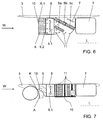
- FIG. 6 shows a plan view of a portion of a motor vehicle 1 according to an embodiment of the invention, during FIG. 7 an associated side view shows.
- the engine and / or unit cooling device 5 is designed as an oblique arrangement, in particular so that it is aligned relative to the vehicle longitudinal axis L obliquely to the side outside, z. B. in an angular range between 30 ° and 60 °.
- a fan device 8 is arranged and, upstream of the fan device 8, the cooling air inlet box 6.
- the fan device 8 serves to pressurize the suction side of the engine and / or unit cooling device 5 with air, for.
- the fan device 8 comprises an air passage 8.1, through which the engine and / or unit cooling device 5 can be acted upon by wind.
- the fan device 8 preferably comprises less than four fan blades, wherein the fan blades can additionally be made relatively narrow.
- a fan device 7 Downstream of the engine and / or unit cooling device 5, a fan device 7 is arranged in order to expel heat from the suction side of the engine and / or unit cooling device 5 expediently in stationary or dust operation of the motor vehicle 1.
- the engine and / or unit cooling device 5 comprises mutually spaced, consecutively arranged engine and / or unit cooling units 5a, 5b and 5c.
- a plurality of air guide elements 11 are provided, the wind from laterally outside the motor vehicle 1 to the engine and / or unit cooling units 5a, 5b and 5c direct.
- So z. B. arranged in the direction of travel W first air guide 11 and be configured to direct airstream from the air inlet box 6 and the fan device 8 to the engine and / or unit cooling unit 5a.
- a longer air guide element 11 can be arranged and designed to direct airstream from laterally outside the motor vehicle 1 toward the engine and / or unit cooling unit 5c.
- a turn downstream air guide element 11 may be arranged and configured to direct airstream from laterally outside the motor vehicle 1 in an outer radiator corner of the engine and / or unit cooling unit 5b.
- the cooling assembly of cooling air inlet box 6, fan device 8, engine and / or unit cooling device 5 and fan device 7 may be complete on the bottom with a protective element 10, z. B. protected a floor panel.
- the top of the cooling assembly may partially or completely with a protective element, for. B be covered a fine-meshed mosquito net.
- the fan device 7 may be provided with a Abströmbegrenzung to prevent heat input in neighboring units or at least reduce.
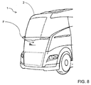
- FIG. 8 shows a perspective view of a motor vehicle front of a motor vehicle 1 according to an embodiment of the invention.
- the vehicle front F of the cab 2 is executed constructive closed area to divide incoming air substantially homogeneous and substantially turbulence-free and to achieve a smooth adjacent flow on the vehicle front F, at the same time it is geometrically adapted for air resistance reduction.
- Dashed line indicates an optional storage space that is accessible via a part of the front side F.
- the engine and / or unit cooling device can not be acted upon by wind, which is supplied via air intakes in the vehicle front. Rather, it can be expedient to use below and / or next to the front of the vehicle F the passing wind for engine and / or engine cooling.
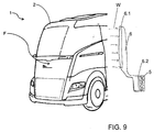
- FIG. 9 shows a perspective view of a motor vehicle 1 according to an embodiment of the invention.
- the cooling air inlet 6.1 of the cooling air inlet box 6 is larger than the cooling air outlet 6.2 of the cooling air inlet box 6, so that a cross section of the cooling air inlet box 6 tapers at least in sections toward the engine and / or unit cooling device 5.
- the cooling air intake box 6 can be arranged on a side wall of the driver's cab 2, preferably such that the cooling air inlet 6.1 extends along the side wall of the driver's cab 2. It is preferred that the cooling air inlet 6.1 extends at a rear, lateral area of the driver's cab 2.
Abstract
Die Erfindung betrifft ein Kraftfahrzeug (1), vorzugsweise einen Lastkraftwagen, insbesondere einen Koffer-Lastkraftwagen. Das Kraftfahrzeug (1) umfasst ein Fahrerhaus (2) und einen Fahrzeugrahmen (3) zur Montage eines Kofferaufbaus (4) und zeichnet sich insbesondere dadurch aus, dass zumindest eine Motor- und/oder Aggregatskühleinrichtung (5) fahrzeugrahmenseitig angeordnet ist.The invention relates to a motor vehicle (1), preferably a truck, in particular a suitcase truck. The motor vehicle (1) comprises a driver's cab (2) and a vehicle frame (3) for mounting a box body (4) and is characterized in particular by the fact that at least one motor and / or aggregate cooling device (5) is arranged on the vehicle frame side.
Description
Die Erfindung betrifft ein Kraftfahrzeug, vorzugsweise einen Lastkraftwagen, insbesondere einen Koffer-Lastkraftwagen mit einem Fahrerhaus und einem Fahrzeugrahmen, insbesondere Fahrzeug-Chassis, zur rahmenfesten, unlösbaren Montage oder rahmenfesten, lösbaren Montage eines Kofferaufbaus.The invention relates to a motor vehicle, preferably a truck, in particular a suitcase truck with a cab and a vehicle frame, in particular vehicle chassis, for frame-fixed, permanent mounting or frame-mounted, detachable mounting a box body.
Aus der
Eine Aufgabe der Erfindung ist es, einen Koffer-Lastkraftwagen zu schaffen, der sich trotz des Erfordernisses einer Motor- und/oder Aggregatskühlung zur Verwendung mit einer konstruktiv geschlossenflächig ausgeführten Fahrerhausfront eignet.It is an object of the invention to provide a box truck which, despite the need for engine and / or engine cooling, is suitable for use with a cab frontally engineered closed face.
Diese Aufgabe kann mit den Merkmalen des unabhängigen Anspruchs gelöst werden. Vorteilhafte Weiterbildungen der Erfindung können den Unteransprüchen und der folgenden Beschreibung bevorzugter Ausführungsformen der Erfindung entnommen werden.This object can be achieved with the features of the independent claim. Advantageous developments of the invention can be taken from the subclaims and the following description of preferred embodiments of the invention.
Die Erfindung schafft ein Kraftfahrzeug, vorzugsweise einen Lastkraftwagen, insbesondere einen Koffer-Lastkraftwagen, mit einem Fahrerhaus und einem Fahrzeugrahmen, insbesondere Fahrzeug-Chassis, zur rahmenfesten, unlösbaren Montage oder zur rahmenfesten, lösbaren Montage eines Kofferaufbaus. Das Kraftfahrzeug zeichnet sich insbesondere dadurch aus, dass zumindest eine Motor- und/oder Aggregatskühleinrichtung fahrzeugrahmenseitig angeordnet ist, insbesondere seitlich außen am Fahrzeugrahmen, zweckmäßig seitlich außen an einem Längsträger des Fahrzeugrahmens oder zwischen zwei Längsträgern des Fahrzeugrahmens.The invention provides a motor vehicle, preferably a truck, in particular a suitcase truck, with a cab and a vehicle frame, in particular vehicle chassis, for frame-mounted, permanent mounting or for frame-mounted, detachable mounting a box body. The motor vehicle is characterized in particular by the fact that at least one engine and / or aggregate cooling device is arranged on the vehicle frame side, in particular laterally on the outside of the vehicle frame, expedient laterally outside on a longitudinal member of the vehicle frame or between two longitudinal members of the vehicle frame.
Der Koffer-Lastkraftwagen kann z. B. einen oder mehrere Anhänger aufweisen. Er kann ferner vorderster Lastkraftwagen eines beliebigen Lastkraftwagen-Gesamt-Zuges sein.The suitcase truck can z. B. have one or more trailers. It may also be the foremost truck of any truck overall train.
Das Fahrerhaus kann als, z. B. zur Motorwartung, abklappbares Fahrerhaus ausgebildet sein.The cab can be used as, for. B. for engine maintenance, fold-down cab be formed.
Die Fahrzeugfront, insbesondere die Front-Außenhaut, des Fahrerhauses ist konstruktiv so geschlossenflächig ausgeführt, dass sie vorzugsweise keinen Lufteinlass zur Motor- und/oder Aggregatskühlung aufweist. Die Fahrzeugfront des Fahrerhauses ist somit vorzugsweise so ausgeführt, dass eine Null-Durchströmung (Umströmung) durch selbige stattfindet. Natürlich kann im Rahmen der Erfindung z. B. unter und/oder neben der Fahrzeugfront des Fahrerhauses Luft, insbesondere Fahrtwind, zur fahrzeugrahmenseitigen Motor- und/oder Aggregatskühleinrichtung gelangen.The vehicle front, in particular the front outer skin, of the driver's cab is of a closed design so that it preferably has no air inlet for engine and / or engine cooling. The vehicle front of the cab is thus preferably designed so that a zero flow (flow) takes place through the same. Of course, in the context of the invention z. B. under and / or next to the vehicle front of the cab air, especially wind, to the vehicle frame side engine and / or aggregate cooling device.
Die Fahrzeugfront ist vorzugsweise kühlergrillfrei, gleichmäßig und somit zweckmäßig aerodynamisch und/oder mit einer geometrischen Anpfeilung zur Luftwiderstandsverbesserung ausgebildet.The vehicle front is preferably grille-free, uniform and thus expedient aerodynamically and / or formed with a geometric Anpfeilung for air resistance improvement.
Die Motor- und/oder Aggregatskühleinrichtung ist zweckmäßig seitlich außen an einem Längsträger des Fahrzeugrahmens angeordnet und z. B. an den Längsträger oder allgemein den Fahrzeugrahmen montiert.The engine and / or unit cooling device is expedient laterally arranged on the outside of a longitudinal member of the vehicle frame and z. B. mounted to the side member or generally the vehicle frame.
Es ist möglich, dass stromaufwärts der Motor- und/oder Aggregatskühleinrichtung ein Kühllufteinlasskasten angeordnet ist, über den z. B. mittelbar oder unmittelbar Luft zur Motor- und/oder Aggregatskühleinrichtung leitbar ist. Über den Kühllufteinlasskasten kann insbesondere Fahrtwind zur Motor- und/oder Aggregatskühleinrichtung geleitet und/oder Luft von einer Ventilatoreinrichtung zur Motor- und/oder Aggregatskühleinrichtung angesaugt werden.It is possible that upstream of the engine and / or unit cooling device, a cooling air inlet box is arranged over the z. B. indirectly or directly air to the engine and / or unit cooling device is conductive. In particular, airstream can be passed to the engine and / or unit cooling device via the cooling air inlet box and / or air can be sucked in by a fan device to the engine and / or unit cooling device.
Vorzugsweise ist ein Kühllufteinlass des Kühllufteinlasskastens kleiner als ein Kühlluftauslass des Kühllufteinlasskastens, so dass sich zweckmäßig ein Luftdurchlassquerschnitt des Kühllufteinlasskastens zumindest abschnittsweise zur Motor- und/oder Aggregatskühleinrichtung hin vergrößert. Alternativ kann ein Kühllufteinlass des Kühllufteinlasskastens größer als ein Kühlluftauslass des Kühllufteinlasskastens sein, so dass sich zweckmäßig ein Luftdurchlassquerschnitt des Kühllufteinlasskastens zumindest abschnittsweise zur Motor- und/oder Aggregatskühleinrichtung hin verjüngt.Preferably, a cooling air inlet of the cooling air inlet box is smaller than a cooling air outlet of the cooling air inlet box, so that expediently an air passage cross section of the cooling air inlet box increases at least in sections toward the engine and / or unit cooling device. Alternatively, a cooling air inlet of the cooling air inlet box may be larger than a cooling air outlet of the cooling air inlet box, so that expediently an air passage cross section of the cooling air inlet box tapers at least in sections toward the engine and / or unit cooling device.
Der Kühlluftauslass des Kühllufteinlasskastens kann sich zweckmäßig über die im Wesentlichen gesamte Breite und/oder Höhe des Kühllufteinlasses der Motor- und/oder Aggregatskühleinrichtung erstrecken.The cooling air outlet of the cooling air inlet box may expediently extend over substantially the entire width and / or height of the cooling air inlet of the engine and / or unit cooling device.
Der Kühllufteinlass des Kühllufteinlasskastens ist zweckmäßig nach oben versetzt, so dass dadurch darunter Bauraum entsteht, z. B. für eine Abgaskomponente des Kraftfahrzeugs. Alternativ oder ergänzend kann der Kühllufteinlass des Kühllufteinlasskastens benachbart zu einem Vorderradkotflügel angeordnet sein, um vom Vorderradkotflügel vor Spritzwasser geschützt zu werden.The cooling air inlet of the cooling air inlet box is expedient offset upwards, thereby creating space under it, z. B. for an exhaust gas component of the motor vehicle. Alternatively or additionally, the cooling air inlet of the cooling air inlet box may be arranged adjacent to a front wheel fender, in order to be protected from splash water by the front wheel fender.
Der Kühllufteinlass des Kühllufteinlasskastens ist zweckmäßig einer Rückseite des Vorderradkotflügels zugewandt und/oder nur in einem hochgelegenen und daher zumindest im Wesentlichen spritzgeschützten Bereich des Fahrzeugrahmens ausgebildet.The cooling air inlet of the cooling air inlet box is expediently facing a rear side of the front mudguard and / or only in a high-lying and therefore at least substantially splash-proof region of the vehicle frame.
Ebenfalls ist es möglich, dass der Kühllufteinlass des Kühllufteinlasskastens sich entlang einer Seitenwand des Fahrerhauses erstreckt, z. B. im Wesentlichen vertikal und/oder in einem hinteren Bereich des Fahrerhauses.It is also possible that the cooling air inlet of the cooling air inlet box extends along a side wall of the cab, for. B. substantially vertically and / or in a rear area of the cab.
Innerhalb des Kühllufteinlasskastens können ein oder mehrere Luftleitelemente, z. B. Luftleitbleche, angeordnet sein, die zusätzlich zur Stabilität des Kühllufteinlasskastens beitragen.Within the cooling air inlet box, one or more air guide elements, for. As baffles, be arranged, which contribute in addition to the stability of the cooling air inlet box.
Stromabwärts der Motor- und/oder Aggregatskühleinrichtung kann eine Ventilatoreinrichtung angeordnet sein, die insbesondere im Stand- oder Staubetrieb des Kraftfahrzeugs erwärmte Luft von der Motor- und/oder Aggregatskühleinrichtung wegbeaufschlagen, insbesondere absaugen kann. Alternativ oder ergänzend kann stromaufwärts der Motor- und/oder Aggregatskühleinrichtung eine Ventilatoreinrichtung angeordnet sein, die insbesondere im Stand- oder Staubetrieb des Kraftfahrzeugs die Motor- und/oder Aggregatskühleinrichtung mit Luft beaufschlagen kann, z. B. über den Kühllufteinlasskasten.Downstream of the engine and / or unit cooling device, a fan device can be arranged, which in particular in the stationary or dust operation of the motor vehicle can expel heated air from the engine and / or unit cooling device, in particular can suck it off. Alternatively or additionally, a fan device can be arranged upstream of the engine and / or unit cooling device, which can apply air to the engine and / or unit cooling device, in particular in stand or dust operation of the motor vehicle, for. B. over the cooling air inlet box.
Die stromaufwärts der Motor- und/oder Aggregatskühleinrichtung angeordnete Ventilatoreinrichtung kann einen Luftdurchlass aufweisen, durch den hindurch die Motor- und/oder Aggregatskühleinrichtung mit Fahrtwind beaufschlagbar ist. Daraus ergibt sich, dass die stromaufwärts der Motor- und/oder Aggregatskühleinrichtung angeordneten Ventilatoreinrichtung vorzugsweise im Wesentlichen parallel zur Längsachse des Kraftfahrzeugs ausgerichtet sein kann.The fan device arranged upstream of the engine and / or unit cooling device may have an air passage through which the engine and / or unit cooling device can be acted upon by wind. It follows that the fan device arranged upstream of the engine and / or unit cooling device can preferably be oriented essentially parallel to the longitudinal axis of the motor vehicle.
Die stromaufwärts der Motor- und/oder Aggregatskühleinrichtung angeordnete Ventilatoreinrichtung umfasst vorzugsweise weniger als vier Ventilatorblätter, so dass möglichst viel Fahrtwind durch die Ventilatoreinrichtung hindurch zur Motor- und/oder Aggregatskühleinrichtung gelangen kann. Zu diesem Zweck können die Ventilatorblätter auch relativ schmal ausgebildet sein. Eine erforderliche Luftmenge bei Fahrzeugstillstand oder niedriger Fahrzeuggeschwindigkeit kann durch eine höhere Ventilatordrehzahl erreicht werden.The fan device arranged upstream of the engine and / or unit cooling device preferably comprises less than four fan blades, so that as much wind as possible can pass through the fan device to the engine and / or unit cooling device. For this purpose, the fan blades can also be made relatively narrow. A required amount of air at vehicle standstill or low vehicle speed can be achieved by a higher fan speed.
Es ist möglich, dass das Kraftfahrzeug einen Luftauslasskasten umfasst, um Luft mittelbar oder unmittelbar aus der Motor- und/oder Aggregatskühleinrichtung, insbesondere aus der stromabwärts der Motor- und/oder Aggregatskühleinrichtung angeordneten Ventilatoreinrichtung, umzulenken, z. B. nach seitlich außen oder nach unten, zweckmäßig zur Fahrbahn hin.It is possible for the motor vehicle to comprise an air outlet box for directing air indirectly or directly out of the engine and / or unit cooling device, in particular from the fan device arranged downstream of the engine and / or unit cooling device, eg. B. to the side outside or down, appropriate to the roadway.
Die Motor- und/oder Aggregatskühleinrichtung ist vorzugsweise im Wesentlichen stehend verbaut.The engine and / or unit cooling device is preferably installed substantially upright.
Die Motor- und/oder Aggregatskühleinrichtung kann z. B. relativ zur Fahrzeuglängsachse im Wesentlichen parallel ausgerichtet sein. Es ist allerdings ebenfalls möglich, dass die Motor- und/oder Aggregatskühleinrichtung relativ zur Fahrzeuglängsachse im Wesentlichen rechtwinklig nach seitlich außen ausgerichtet ist. Des Weiteren ist eine Schrägausrichtung der Motor- und/oder Aggregatskühleinrichtung möglich, insbesondere so, dass sie relativ zur Fahrzeuglängsachse schräg ausgerichtet ist, z. B. in einem Winkelbereich von 25° bis 75°, vorzugsweise 45° +/- 10°.The engine and / or unit cooling device may, for. B. be aligned relative to the vehicle longitudinal axis substantially parallel. However, it is also possible that the engine and / or unit cooling device is oriented relative to the vehicle longitudinal axis substantially at right angles to the side outside. Furthermore, an oblique orientation of the engine and / or unit cooling device is possible, in particular so that it is oriented obliquely relative to the vehicle longitudinal axis, for. B. in an angular range of 25 ° to 75 °, preferably 45 ° +/- 10 °.
Bei Schrägausrichtung der Motor- und/oder Aggregatskühleinrichtung kann die Motor- und/oder Aggregatskühleinrichtung sowohl von seitlich außen als auch über den Lufteinlasskasten mit Fahrtwind beaufschlagt werden.In oblique orientation of the engine and / or unit cooling device, the engine and / or aggregate cooling device can be acted upon both from the outside and via the air intake box with wind.
Das Kraftfahrzeug kann zumindest ein Luftleitelement aufweisen, um Fahrtwind von seitlich außerhalb des Kraftfahrzeugs, insbesondere des Fahrzeugrahmens, hin zur Motor- und/oder Aggregatskühleinrichtung zu lenken.The motor vehicle may have at least one air-guiding element in order to direct wind from laterally outside the motor vehicle, in particular the vehicle frame, toward the engine and / or unit cooling device.
Die stromaufwärts der Motor- und/oder Aggregatskühleinrichtung angeordnete Ventilatoreinrichtung kann die Motor- und/oder Aggregatskühleinrichtung z .B. schräg anblasen.The fan device arranged upstream of the engine and / or unit cooling device may be the engine and / or unit cooling device z .B. blow at an angle.
Es ist möglich, dass die Motor- und/oder Aggregatskühleinrichtung mehrere, z. B. zumindest drei, voneinander beabstandete, zweckmäßig in Luftströmungsrichtung hintereinander angeordnete Motor- und/oder Aggregatskühleinheiten umfasst. Die Motor- und/oder Aggregatskühleinheiten dienen vorzugsweise unterschiedlichen Kühlzwecken, z. B. der Motorkühlung, der Getriebeölkühlung, der Zwischenkühlung komprimierter Ansaugluft, etc.It is possible that the engine and / or unit cooling device several, z. B. at least three, spaced apart, expediently in the air flow direction successively arranged engine and / or unit cooling units comprises. The engine and / or unit cooling units preferably serve different cooling purposes, eg. As the engine cooling, the transmission oil cooling, the intermediate cooling of compressed intake air, etc.
Eine Motor- und/oder Aggregatskühleinheit kann somit z. B. zur Motorkühlung dienen. Eine andere Motor- und/oder Aggregatskühleinheit kann z. B. zur Zwischenkühlung komprimierter Ansaugluft dienen, insbesondere stromabwärts eines Turboladers. Eine andere Motor- und/oder Aggregatskühleinheit kann alternativ oder ergänzend zur Getriebeölkühlung dienen.An engine and / or unit cooling unit can thus z. B. serve for engine cooling. Another engine and / or unit cooling unit may, for. B. are used for intermediate cooling compressed intake air, in particular downstream of a turbocharger. Another engine and / or unit cooling unit may serve as an alternative or in addition to the transmission oil cooling.
Es ist möglich, dass zwischen den Motor- und/oder Aggregatskühleinheiten eine Ventilatoreinrichtung angeordnet ist.It is possible that a fan device is arranged between the engine and / or unit cooling units.
Das Kraftfahrzeug kann mehrere unterschiedlich ausgebildete, vorzugsweise an unterschiedlichen Positionen angeordnete, Luftleitelemente aufweisen, um Fahrtwind von seitlich außerhalb des Kraftfahrzeugs, insbesondere des Fahrzeugrahmens, hin zu den Motor- und/oder Aggregatskühleinheiten zu leiten. Dadurch kann z. B. gewährleistet werden, dass die voneinander beabstandeten, z. B. hintereinander angeordneten Motor- und/oder Aggregatskühleinheiten mittels den Luftleitelementen zweckmäßig unmittelbar mit Fahrtwind beaufschlagt werden.The motor vehicle may have a plurality of differently designed, preferably arranged at different positions, air guide elements to guide airflow from the side outside the motor vehicle, in particular of the vehicle frame, to the engine and / or unit cooling units. As a result, z. B. be ensured that the spaced apart, z. B. successively arranged engine and / or unit cooling units by means of the air guide elements expediently be directly impacted with airstream.
Es ist möglich, dass zumindest eines von folgenden im Bauraum verbaut ist, der sich in Längsrichtung des Kraftfahrzeugs hinter dem Vorderradkotflügel, seitlich außerhalb des Fahrzeugrahmens und/oder unter dem Niveau des Kofferaufbaus erstreckt: die Motor- und/oder Aggregatskühleinrichtung, der Kühllufteinlasskasten, die stromaufwärts der Motor- und/oder Aggregatskühleinrichtung angeordnete Ventilatoreinrichtung, die stromabwärts der Motor- und/oder Aggregatskühleinrichtung angeordnete Ventilatoreinrichtung und/oder der Luftauslasskasten. Der Bauraum kann zweckmäßig seitlich außen von einem Seitenaufprallschutz begrenzt werden. Somit kann sich seitlich außerhalb der Motor- und/oder Aggregatskühleinrichtung, und vorzugsweise des Kühllufteinlasskastens, der stromaufwärts der Motor- und/oder Aggregatskühleinrichtung angeordneten Ventilatoreinrichtung, der stromabwärts der Motor- und/oder Aggregatskühleinrichtung angeordneten Ventilatoreinrichtung und/oder des Luftauslasskastens, ein Seitenaufprallschutz erstreckt.It is possible that at least one of the following is installed in the installation space which extends in the longitudinal direction of the motor vehicle behind the front fender, laterally outside the vehicle frame and / or below the level of the box body: the engine and / or unit cooling device, the cooling air inlet box Fan means arranged upstream of the engine and / or unit cooling means, the fan means arranged downstream of the motor and / or unit cooling means, and / or the air outlet box. The space can be conveniently limited laterally outside of a side impact protection. Thus, laterally outside the motor and / or aggregate cooling device, and preferably the cooling air inlet box, the fan means located upstream of the motor and / or aggregate cooling means, the fan means located downstream of the motor and / or aggregate cooling means, and / or the air outlet box, side impact protection may extend ,
Es ist möglich, dass ein Kraftstofftank zwischen Längsträgern des Fahrzeugrahmens angeordnet ist, so dass auf der Fahrzeugrahmenseite, auf der die Motor- und/oder Aggregatskühleinrichtung angeordnet ist, kein Kraftstofftank angeordnet ist.It is possible that a fuel tank is arranged between longitudinal members of the vehicle frame, so that no fuel tank is arranged on the vehicle frame side on which the engine and / or unit cooling device is arranged.
Zumindest einige der zuvor beschriebenen Bauteile können durch Störpartikel, z. B. Schmutz, Spritzwasser, Steinchen, etc. beschädigt werden oder beeinträchtigt werden.At least some of the components described above may be affected by spurious particles, e.g. As dirt, water spray, stones, etc. are damaged or impaired.
Zu diesem Zweck kann zumindest eines von folgenden mit einem Schutzelement versehen werden: die Motor- und/oder Aggregatskühleinrichtung, der Kühllufteinlasskasten, die stromaufwärts der Motor- und/oder Aggregatskühleinrichtung angeordnete Ventilatoreinrichtung, die stromabwärts der Motor- und/oder Aggregatskühleinrichtung angeordnete Ventilatoreinrichtung und/oder der Luftauslasskasten. Das Schutzelement ist zweckmäßig ausgeführt, um einen Luftdurchtritt zu gewährleisten, allerdings vor einem Eindringen von Störpartikeln, z. B. Schmutz, Steinchen, Spritzwasser, zu schützen. Hierzu kann das Schutzelement z. B. perforiert sein und/oder als Abschirmblende ausgeführt sein. Das Schutzelement kann z. B. ein zweckmäßig feinmaschiges Schutzgitter, ein Bodenblech und/oder ein zweckmäßig feinmaschiges Fliegennetz umfassen.For this purpose, at least one of the following can be provided with a protective element: the motor and / or aggregate cooling device, the cooling air inlet box, the fan device arranged upstream of the motor and / or aggregate cooling device, the fan device arranged downstream of the motor and / or aggregate cooling device, and / or or the air outlet box. The protective element is suitably designed to ensure an air passage, but against the ingress of interfering particles, eg. As dirt, pebbles, splash water to protect. For this purpose, the protective element z. B. be perforated and / or be designed as shielding. The protective element can, for. B. a purposefully fine-meshed protective grid, a floor panel and / or a purposefully fine-meshed mosquito net.
Die zuvor beschriebenen Bauteile, also insbesondere die Motor- und/oder Aggregatskühleinrichtung, der Kühllufteinlasskasten, die stromaufwärts der Motor- und/oder Aggregatskühleinrichtung angeordnete Ventilatoreinrichtung, die stromabwärts der Motor- und/oder Aggregatskühleinrichtung angeordnete Ventilatoreinrichtung und/oder der Luftauslasskasten, können eine Kühlerbaugruppe bilden, die z. B. auf nur einer Fahrzeugrahmenseite verbaut ist oder auf beiden Fahrzeugrahmenseiten verbaut ist. Ebenfalls ist es möglich, dass mehrere Kühlerbaugruppen auf einer Fahrzeugrahmenseite verbaut werden.The components described above, in particular the engine and / or unit cooling device, the cooling air inlet box, the fan device arranged upstream of the motor and / or aggregate cooling device, the fan device arranged downstream of the motor and / or aggregate cooling device and / or the air outlet box, can form a cooler assembly form, the z. B. is installed on only one vehicle frame side or installed on both sides of the vehicle frame. It is also possible that a plurality of radiator assemblies are installed on a vehicle frame side.
Das Kraftfahrzeug ist, wie schon zuvor erwähnt, zweckmäßig ein Lastkraftwagen, insbesondere ein sogenannter Koffer-Lastkraftwagen mit einem Kofferaufbau. Der Kofferaufbau ist vorzugsweise fest, insbesondere unlösbar an den Fahrzeugrahmen montiert. Alternativ kann der Kofferaufbau auch als sogenannter Wechselkofferaufbau ausgeführt sein, so dass der Fahrzeugrahmen zur wechselbaren Montage des Kofferaufbaus ausgeführt sein kann.The motor vehicle is, as already mentioned, expediently a truck, in particular a so-called suitcase truck with a box body. The box body is preferably fixed, in particular permanently mounted to the vehicle frame. Alternatively, the box body can be designed as a so-called swap body, so that the vehicle frame can be designed for changeable mounting of the box body.
Das Kraftfahrzeug ist insbesondere keine Sattelzugmaschine.In particular, the motor vehicle is not a tractor-trailer.
Zu erwähnen ist außerdem, dass der Fahrzeugrahmen insbesondere das Fahrzeugchassis ist.It should also be mentioned that the vehicle frame is in particular the vehicle chassis.
Zu erwähnen ist des Weiteren, dass die Motorkühleinrichtung zweckmäßig zum Kühlen eines Motors zum Antreiben des Kraftfahrzeugs ausgeführt ist und/oder die Aggregatskühleinrichtung zweckmäßig zum Kühlen eines Kraftfahrzeugs-Aggregats ausgeführt ist.It should also be mentioned that the engine cooling device is expediently designed for cooling a motor for driving the motor vehicle and / or the unit cooling device is expediently designed for cooling a motor vehicle aggregate.
Zu erwähnen ist noch, dass über den Kühllufteinlasskasten Fahrtwind einströmbar und zur Motor- und/oder Aggregatskühleinrichtung leitbar ist, aber vorzugsweise auch Luft mittels einer Ventilatoreinrichtung für die Motor- und/oder Aggregatskühleinrichtung ansaugbar ist, z. B. im Stand- oder Staubetrieb des Kraftfahrzeugs.It should also be mentioned that via the cooling air inlet box airstream can be flowed in and the engine and / or unit cooling device can be conducted, but preferably also air can be sucked by means of a fan device for the engine and / or unit cooling device, for. B. in stationary or storage operation of the motor vehicle.
Die zweckmäßig geschlossenflächige Fahrzeugfront des Fahrerhauses kann z. B. zumindest teilweise aus Kunststoff, Verbundwerkstoff und/oder Metall (z. B. Blech) ausgeführt sein und/oder eine geometrische Anpfeilung zur Luftwiderstandsverbesserung umfassen.The functional closed-area vehicle front of the cab can z. B. at least partially made of plastic, composite material and / or metal (eg., Sheet metal) be executed and / or include a geometric Anpfeilung for air resistance improvement.
Die oben beschriebenen bevorzugten Ausführungsformen der Erfindung sind beliebig miteinander kombinierbar. Andere vorteilhafte Weiterbildungen der Erfindung sind in den Unteransprüchen offenbart oder ergeben sich aus der folgenden Beschreibung bevorzugter Ausführungsformen der Erfindung in Verbindung mit den beigefügten Figuren.
Figur 1- zeigt eine Seitenansicht eines Kraftfahrzeugs gemäß einer Ausführungsform der Erfindung,
Figur 2- zeigt eine Draufsicht auf einen Teilbereich eines Kraftfahrzeugs gemäß einer Ausführungsform der Erfindung,
Figur 3- zeigt eine Seitenansicht des Teilbereichs der
Figur 2 , Figur 4- zeigt eine Draufsicht auf einen Teilbereich eines Kraftfahrzeugs gemäß einer Ausführungsform der Erfindung,
Figur 5- zeigt eine Seitenansicht des Teilbereichs der
Figur 4 , Figur 6- zeigt eine Draufsicht auf einen Teilbereich eines Kraftfahrzeugs gemäß einer Ausführungsform der Erfindung,
Figur 7- zeigt eine Seitenansicht des Teilbereichs der
Figur 6 , Figur 8- zeigt eine perspektivische Ansicht einer Kraftfahrzeugfront gemäß einer Ausführungsform der Erfindung, und
Figur 9- zeigt eine perspektivische Ansicht eines Kraftfahrzeugs gemäß einer Ausführungsform der Erfindung.
- FIG. 1
- shows a side view of a motor vehicle according to an embodiment of the invention,
- FIG. 2
- shows a plan view of a portion of a motor vehicle according to an embodiment of the invention,
- FIG. 3
- shows a side view of the portion of the
FIG. 2 . - FIG. 4
- shows a plan view of a portion of a motor vehicle according to an embodiment of the invention,
- FIG. 5
- shows a side view of the portion of the
FIG. 4 . - FIG. 6
- shows a plan view of a portion of a motor vehicle according to an embodiment of the invention,
- FIG. 7
- shows a side view of the portion of the
FIG. 6 . - FIG. 8
- shows a perspective view of a motor vehicle front according to an embodiment of the invention, and
- FIG. 9
- shows a perspective view of a motor vehicle according to an embodiment of the invention.
Die unter Bezugnahme auf die Figuren beschriebenen Ausführungsformen stimmen teilweise überein, so dass ähnliche oder identische Teile mit den gleichen Bezugszeichen versehen sind und zu deren Erläuterung auch auf die Beschreibung der anderen Figuren bzw. Ausführungsformen verwiesen wird, um Wiederholungen zu vermeiden.The embodiments described with reference to the figures are partially identical, so that similar or identical parts are provided with the same reference numerals and to the explanation of which reference is made to the description of the other figures or embodiments in order to avoid repetition.
Das Kraftfahrzeug 1 weist ein Fahrerhaus 2 und einen Fahrzeugrahmen (Fahrzeugchassis) 3 zur rahmenfest unlösbaren oder rahmenfest lösbaren Montage eines Kofferaufbaus 4 auf. Die Fahrzeugfront F des Fahrerhauses 2 ist konstruktiv, bauartbedingt geschlossenflächig ausgeführt, so dass sie keinen Lufteinlass für eine Motor- und/oder Aggregatskühlung aufweist und insoweit eine luftundurchströmte Fahrzeugfront F darstellt. Im Gegensatz zu üblichen Koffer-Lastkraftwägen kann eine erforderliche Motor- und/oder Aggregatskühleinrichtung folglich nicht über Fahrtwind beaufschlagt werden, der über Lufteinlässe in der Fahrzeugfront zugeführt wird.The
Das Kraftfahrzeug 1 zeichnet sich deshalb insbesondere dadurch aus, dass eine Motor- und/oder Aggregatskühleinrichtung 5 fahrzeugrahmenseitig und somit zweckmäßig chassisseitig angeordnet ist, vorzugsweise seitlich außen am Fahrzeugrahmen 3, so dass zweckmäßig Fahrtwind, der unter und/oder neben der Fahrzeugfront F vorbeiströmt, zur Motor- und/oder Aggregatskühlung nutzbar ist.The
Stromaufwärts der Motor- und/oder Aggregatskühleinrichtung 5 ist ein Kühllufteinlasskasten 6 angeordnet, über den Fahrtwind W zur Motor- und/oder Aggregatskühleinrichtung 5 leitbar ist.Upstream of the engine and / or
Stromabwärts der Motor- und/oder Aggregatskühleinrichtung 5 ist eine Ventilatoreinrichtung 7 angeordnet zur zweckmäßigen Absaugung erwärmter Luft von der Motor- und/oder Aggregatskühleinrichtung 5, insbesondere deren Kühlrippen, was insbesondere im Stand- oder Staubetrieb des Kraftfahrzeugs 1 erforderlich werden kann.Downstream of the engine and / or
Stromabwärts der Ventilatoreinrichtung 7 ist ein Luftauslasskasten 9, insbesondere ein Absaugkasten, angeordnet, um Luft aus der Motor- und/oder Aggregatskühleinrichtung 5 und insbesondere der Ventilatoreinrichtung 7 nach unten hin zur Fahrbahn umzulenken. Bezugszeichen K kennzeichnet einen Vorderradkotflügel, während Bezugszeichen T einen Kraftstofftank kennzeichnet.Downstream of the
Es wird ersichtlich, dass die Kühlerbaugruppe aus Motor- und/oder Aggregatskühleinrichtung 5, Kühllufteinlasskasten 6, Ventilatoreinrichtung 7 und Luftauslasskasten 9 in Längsrichtung L des Kraftfahrzeugs 1 zwischen dem Vorderradkotflügel K und dem Kraftstofftank T angeordnet ist.It can be seen that the radiator assembly of engine and / or
Der Kühllufteinlasskasten 6 umfasst einen Kühllufteinlass 6.1 und einen Kühlluftauslass 6.2.The cooling
Eine weitere Besonderheit des Kühllufteinlasskastens 6 ist, dass dessen Kühllufteinlass 6.1 benachbart zum Vorderradkotflügel K angeordnet ist, so dass er vom Vorderradkotflügel K vor Spritzwasser geschützt wird. Der Kühllufteinlass 6.1 ist nach oben versetzt, so dass darunter Bauraum z. B. für eine Abgaskomponente A des Kraftfahrzeugs 1 entsteht.Another special feature of the cooling
Das Innere des Kühllufteinlasskastens 6 kann aufgrund seiner Gesamtform mit einigen Luftleitelementen versehen sein, die zusätzlich zur Stabilität des Kühllufteinlasskastens 6 beitragen.The interior of the cooling
Erfordert es die Gesamtkühlleistung aller Aggregate und/oder Motorabschnitte, können zwei Kühlbaugruppen aus Kühllufteinlasskasten 6, Motor- und/oder Aggregatskühleinrichtung 5, Ventilatoreinrichtung 7 und zweckmäßig Luftauslasskasten 9 vorgesehen werden, die z. B. seriell hintereinander auf einer Fahrzeugrahmenseite oder zumindest eine auf der einen Fahrzeugrahmenseite und zumindest eine auf der anderen Fahrzeugrahmenseite angeordnet werden können. Der Luftauslasskasten 9 kann insbesondere dann weggelassen werden, wenn dahinter kein Kraftstofftank T angeordnet ist.If it requires the total cooling capacity of all units and / or engine sections, two cooling assemblies from cooling
Aus den
Eine Besonderheit der in den
Um ein Eindringen von Störpartikeln in die Motor- und/oder Aggregatskühleinrichtung 5 zu verhindern oder zumindest zu reduzieren, ist die Motor- und/oder Aggregatskühleinrichtung 5 mit einem Schutzelement 10, z. B. einem Abdeckgitter versehen.In order to prevent or at least reduce the penetration of interfering particles into the engine and / or
Ebenfalls kann die Ansaugseite der Ventilatoreinrichtung 7 ein Schutzelement 10 z. B. in Form eines üblichen feinmaschigen Netzes umfassen. Ebenfalls kann ein zusätzliches Schutzelement in Form eines Bodenblechs auf der Ansaugseite der Ventilatoreinrichtung 7 zur Luftreinhaltung angesaugter Luft beitragen.Also, the suction side of the
Eine Besonderheit der in den
Stromaufwärts der Motor- und/oder Aggregatskühleinrichtung 5 ist eine Ventilatoreinrichtung 8 angeordnet und stromaufwärts der Ventilatoreinrichtung 8 der Kühllufteinlasskasten 6.Upstream of the engine and / or
Die Ventilatoreinrichtung 8 dient dazu, die Ansaugseite der Motor- und/oder Aggregatskühleinrichtung 5 mit Luft zu beaufschlagen, z. B. in einem Stand- oder Staubetrieb des Kraftfahrzeugs 1. Die Ventilatoreinrichtung 8 umfasst einen Luftdurchlass 8.1, durch den hindurch die Motor- und/oder Aggregatskühleinrichtung 5 mit Fahrtwind beaufschlagbar ist. Damit möglichst viel Fahrtwind die Ventilatoreinrichtung 8 durchströmen kann, umfasst die Ventilatoreinrichtung 8 vorzugsweise weniger als vier Ventilatorblätter, wobei die Ventilatorblätter zusätzlich relativ schmal ausgeführt sein können.The
Stromabwärts der Motor- und/oder Aggregatskühleinrichtung 5 ist eine Ventilatoreinrichtung 7 angeordnet, um zweckmäßig im Stand- oder Staubetrieb des Kraftahrzeugs 1 Wärme von der Absaugseite der Motor- und/oder Aggregatskühleinrichtung 5 abzusaugen.Downstream of the engine and / or
Die Motor- und/oder Aggregatskühleinrichtung 5 umfasst voneinander beabstandete, hintereinander angeordnete Motor- und/oder Aggregatskühleinheiten 5a, 5b und 5c. Um die Motor- und/oder Aggregatskühleinheiten 5a, 5b und 5c mit Fahrtwind zu beaufschlagen, sind mehrere Luftleitelemente 11 vorgesehen, die Fahrtwind von seitlich außerhalb des Kraftfahrzeugs 1 hin zu den Motor- und/oder Aggregatskühleinheiten 5a, 5b und 5c lenken.The engine and / or
So kann z. B. ein in Fahrtwindrichtung W erstes Luftleitelement 11 angeordnet und ausgebildet sein, um Fahrtwind aus dem Lufteinlasskasten 6 und der Ventilatoreinrichtung 8 auf die Motor- und/oder Aggregatskühleinheit 5a zu lenken.So z. B. arranged in the direction of travel W
Nachgeordnet kann ein längeres Luftleitelement 11 angeordnet und ausgebildet sein, um Fahrtwind von seitlich außerhalb des Kraftfahrzeugs 1 hin zur Motor- und/oder Aggregatskühleinheit 5c zu lenken.Downstream, a longer
Ferner kann ein wiederum nachgeordnetes Luftleitelement 11 angeordnet und ausgebildet sein, um Fahrtwind von seitlich außerhalb des Kraftfahrzeugs 1 in eine äußere Kühlerecke der Motor- und/oder Aggregatskühleinheit 5b zu lenken.Furthermore, a turn downstream
Die Kühlbaugruppe aus Kühllufteinlasskasten 6, Ventilatoreinrichtung 8, Motor- und/oder Aggregatskühleinrichtung 5 und Ventilatoreinrichtung 7 kann an der Unterseite komplett mit einem Schutzelement 10, z. B. einem Bodenblech geschützt sein. Die Oberseite der Kühlbaugruppe kann teilweise oder komplett mit einem Schutzelement, z. B einem feinmaschigen Fliegennetz abgedeckt werden.The cooling assembly of cooling
Die Ventilatoreinrichtung 7 kann mit einer Abströmbegrenzung versehen sein, um einen Wärmeeintrag in Nachbaraggregate zu verhindern oder zumindest zu reduzieren.The
Es ist möglich, zwischen den Motor- und/oder Aggregatskühleinheiten 5a, 5b und 5c eine Ventilatoreinrichtung anzuordnen.It is possible to arrange a fan device between the engine and / or
Die Fahrzeugfront F des Fahrerhauses 2 ist konstruktiv geschlossenflächig ausgeführt, um anströmende Luft im Wesentlichen homogen und im Wesentlichen verwirbelungsfrei zu teilen und eine glatt anliegende Weiterströmung an der Fahrzeugfront F zu erreichen, zugleich ist sie geometrisch angepfeilt zur Luftwiderstandsreduzierung. Die in
Im Gegensatz zu üblichen Koffer-Lastkraftwägen kann die Motor- und/oder Aggregatskühleinrichtung nicht über Fahrtwind beaufschlagt werden, der über Lufteinlässe in der Fahrzeugfront zugeführt wird. Vielmehr kann zweckmäßig unter und/oder neben der Fahrzeugfront F vorbeiströmender Fahrtwind zur Motor- und/oder Aggregatskühlung genutzt werden.In contrast to conventional suitcase trucks, the engine and / or unit cooling device can not be acted upon by wind, which is supplied via air intakes in the vehicle front. Rather, it can be expedient to use below and / or next to the front of the vehicle F the passing wind for engine and / or engine cooling.
Eine Besonderheit der in
Die Erfindung ist nicht auf die oben beschriebenen bevorzugten Ausführungsformen beschränkt. Vielmehr ist eine Vielzahl von Varianten und Abwandlungen möglich, die ebenfalls von dem Erfindungsgedanken Gebrauch machen und deshalb in den Schutzbereich fallen. Darüber hinaus beansprucht die Erfindung auch Schutz für den Gegenstand und die Merkmale der Unteransprüche unabhängig von den in Bezug genommenen Merkmalen und Ansprüchen.The invention is not limited to the preferred embodiments described above. Rather, a variety of variants and modifications is possible, which also make use of the inventive idea and therefore fall within the scope. Moreover, the invention also claims protection of the subject matter and the features of the subclaims independently of the features and claims referred to.
- 11
- Kraftfahrzeugmotor vehicle
- 22
- Fahrerhausdriver's cab
- 33
- Fahrzeugrahmen, insbesondere Fahrzeugchassis, zur Montage eines KofferaufbausVehicle frame, in particular vehicle chassis, for mounting a box body
- 44
- KofferaufbauKofferaufbau
- 55
- Motor- und/oder AggregatskühleinrichtungEngine and / or unit cooling device
- 5.15.1
- Kühllufteinlass der Motor- und/oder AggregatskühleinrichtungCooling air inlet of the engine and / or unit cooling device
- 66
- KühllufteinlasskastenCooling air intake box
- 6.16.1
- Kühllufteinlass des KühllufteinlasskastensCooling air inlet of the cooling air inlet box
- 6.26.2
- Kühlluftauslass des KühllufteinlasskastensCooling air outlet of the cooling air intake box
- 77
- Ventilatoreinrichtung, insbesondere stromabwärts der Motor- und/oder AggregatskühleinrichtungFan device, in particular downstream of the engine and / or unit cooling device
- 88th
- Ventilatoreinrichtung, insbesondere stromaufwärts der Motor- und/oder AggregatskühleinrichtungFan device, in particular upstream of the engine and / or unit cooling device
- 99
- Luftauslasskastenoutlet box
- 1010
- Schutzelement(e)Protective element (s)
- 1111
- Luftleitelement(e)Air guiding element (s)
- FF
- Fahrzeugfront, insbesondere Front-AußenhautVehicle front, especially front outer skin
- LL
- Fahrzeuglängsachsevehicle longitudinal axis
- WW
- Fahrtwindrichtung / FahrtwindForward wind direction / airstream
- KK
- Vorderradkotflügelfront fender
- TT
- KraftstofftankFuel tank
- AA
- Abgaskomponenteexhaust gas component
Claims (21)
Applications Claiming Priority (1)
| Application Number | Priority Date | Filing Date | Title |
|---|---|---|---|
| DE102015009364.9A DE102015009364A1 (en) | 2015-07-17 | 2015-07-17 | Motor vehicle, preferably suitcase trucks with engine and / or aggregate cooling device |
Publications (3)
| Publication Number | Publication Date |
|---|---|
| EP3118091A2 true EP3118091A2 (en) | 2017-01-18 |
| EP3118091A3 EP3118091A3 (en) | 2017-03-22 |
| EP3118091B1 EP3118091B1 (en) | 2019-08-07 |
Family
ID=56296450
Family Applications (1)
| Application Number | Title | Priority Date | Filing Date |
|---|---|---|---|
| EP16001437.9A Active EP3118091B1 (en) | 2015-07-17 | 2016-06-27 | Motor vehicle, preferably box trucks with motor and/or aggregate cooling |
Country Status (2)
| Country | Link |
|---|---|
| EP (1) | EP3118091B1 (en) |
| DE (1) | DE102015009364A1 (en) |
Cited By (1)
| Publication number | Priority date | Publication date | Assignee | Title |
|---|---|---|---|---|
| WO2024017733A1 (en) * | 2022-07-18 | 2024-01-25 | Man Truck & Bus Se | Motor vehicle with temperature control device |
Families Citing this family (1)
| Publication number | Priority date | Publication date | Assignee | Title |
|---|---|---|---|---|
| DE102016009064B4 (en) * | 2016-07-26 | 2019-03-21 | Audi Ag | vehicle |
Citations (1)
| Publication number | Priority date | Publication date | Assignee | Title |
|---|---|---|---|---|
| DE102013007464A1 (en) | 2013-04-30 | 2014-10-30 | Man Truck & Bus Ag | Cab with backside radiator |
Family Cites Families (7)
| Publication number | Priority date | Publication date | Assignee | Title |
|---|---|---|---|---|
| JP3758631B2 (en) * | 2002-10-15 | 2006-03-22 | 三菱ふそうトラック・バス株式会社 | Motor cooling structure for hybrid electric vehicle |
| US7314106B2 (en) * | 2004-04-02 | 2008-01-01 | Freightliner Llc | Vehicle chassis with side mounted air intake plenum |
| DE102005033331A1 (en) * | 2005-07-16 | 2007-01-25 | Daimlerchrysler Ag | Radiator arrangement for a truck comprises a radiator module and a fan hood fixed to the chassis of a vehicle |
| DE102007050191A1 (en) * | 2007-10-20 | 2009-04-23 | Daimler Ag | Front area for e.g. commercial motor vehicle, has cooling module arranged in installation space limited by cross beams, where cooling module has collecting body, and multiple lines communicating with collecting body |
| SE532307C2 (en) * | 2008-04-29 | 2009-12-08 | Scania Cv Ab | Device for cooling an area behind a vehicle engine |
| US20140021711A1 (en) * | 2010-05-03 | 2014-01-23 | Shem, Llc | Heavy Duty Truck Chassis Having Rear Mounted Fuel Tank |
| DE102011109025A1 (en) * | 2011-07-30 | 2012-04-19 | Daimler Ag | Protection arrangement for high-voltage battery of hybrid commercial motor vehicle, has deformation elements arranged outside of battery for absorption of crash energy during force application caused by accident |
-
2015
- 2015-07-17 DE DE102015009364.9A patent/DE102015009364A1/en not_active Withdrawn
-
2016
- 2016-06-27 EP EP16001437.9A patent/EP3118091B1/en active Active
Patent Citations (1)
| Publication number | Priority date | Publication date | Assignee | Title |
|---|---|---|---|---|
| DE102013007464A1 (en) | 2013-04-30 | 2014-10-30 | Man Truck & Bus Ag | Cab with backside radiator |
Cited By (1)
| Publication number | Priority date | Publication date | Assignee | Title |
|---|---|---|---|---|
| WO2024017733A1 (en) * | 2022-07-18 | 2024-01-25 | Man Truck & Bus Se | Motor vehicle with temperature control device |
Also Published As
| Publication number | Publication date |
|---|---|
| DE102015009364A1 (en) | 2017-01-19 |
| EP3118091A3 (en) | 2017-03-22 |
| EP3118091B1 (en) | 2019-08-07 |
Similar Documents
| Publication | Publication Date | Title |
|---|---|---|
| DE112013000178B3 (en) | hydraulic excavators | |
| EP3570961B1 (en) | Road vehicle having an ambient air purification device | |
| DE60204753T2 (en) | WATER-EXHAUSTIVE FENDER FOR MOTOR VEHICLES AND THE SAME | |
| DE102014004303A1 (en) | Vehicle battery pack device | |
| DE2618920A1 (en) | AIR CONVEYOR DEVICE ON A COOLER FOR COMBUSTION ENGINE | |
| DE102012010002A1 (en) | wind-deflecting | |
| DE102006014443A1 (en) | Motor vehicle`s front end, has auxiliary inlet provided within track facing region of end, where inlet is provided in laterally external region before front wheels of motor vehicle, and bumper covering is pulled downward | |
| DE102012006818B4 (en) | muffler | |
| EP2799272B1 (en) | Driver's cab with rear flat cooler | |
| EP3118091B1 (en) | Motor vehicle, preferably box trucks with motor and/or aggregate cooling | |
| DE3716701A1 (en) | AERODYNAMICALLY TRAINED FAIRING PART FOR THE BOTTOM OF A MOTOR VEHICLE | |
| DE102006044952B4 (en) | Device for air-cooling a wheel brake on a motor vehicle | |
| EP1522688B1 (en) | Self-propelled road milling machine with a cooling system | |
| EP3260359A1 (en) | Wind guidance element to be mounted on a sidewall for a vehicle | |
| DE102008061538A1 (en) | Channel arrangement for guiding process air to an internal combustion engine | |
| EP1683919B1 (en) | Device for cleaning road surfaces | |
| DE102019120166B4 (en) | All-terrain vehicle, especially pick-up | |
| DE102013008824B4 (en) | Driver's cab for a commercial vehicle with an aerodynamic windshield device arranged on a driver's cab roof | |
| DE102010016664A1 (en) | Self-propelled agricultural machine | |
| EP3556593B1 (en) | Work vehicle with a coolant air deflection device at the outlet | |
| DE102009023771A1 (en) | Self-driven harvesting machine i.e. combine harvester, has three radiator elements that are arranged within upper-lateral region of machine in horizontally aligned manner, where radiator elements guide cooling air flow in vertical direction | |
| DE202021104097U1 (en) | Automotive air guide and automotive vehicle | |
| DE102007035303A1 (en) | Channel arrangement for feeding process air to internal combustion engine of vehicle, particularly passenger car, comprises air feed channel, which is connected with air filter housing | |
| DE2755476A1 (en) | DEVICE FOR REDUCING AIR RESISTANCE IN TRUCK VEHICLES | |
| EP4308440A1 (en) | Semitrailer tractor unit and semitrailer |
Legal Events
| Date | Code | Title | Description |
|---|---|---|---|
| PUAI | Public reference made under article 153(3) epc to a published international application that has entered the european phase |
Free format text: ORIGINAL CODE: 0009012 |
|
| STAA | Information on the status of an ep patent application or granted ep patent |
Free format text: STATUS: THE APPLICATION HAS BEEN PUBLISHED |
|
| AK | Designated contracting states |
Kind code of ref document: A2 Designated state(s): AL AT BE BG CH CY CZ DE DK EE ES FI FR GB GR HR HU IE IS IT LI LT LU LV MC MK MT NL NO PL PT RO RS SE SI SK SM TR |
|
| AX | Request for extension of the european patent |
Extension state: BA ME |
|
| PUAL | Search report despatched |
Free format text: ORIGINAL CODE: 0009013 |
|
| AK | Designated contracting states |
Kind code of ref document: A3 Designated state(s): AL AT BE BG CH CY CZ DE DK EE ES FI FR GB GR HR HU IE IS IT LI LT LU LV MC MK MT NL NO PL PT RO RS SE SI SK SM TR |
|
| AX | Request for extension of the european patent |
Extension state: BA ME |
|
| RIC1 | Information provided on ipc code assigned before grant |
Ipc: B60K 15/063 20060101ALI20170213BHEP Ipc: B60K 11/04 20060101ALI20170213BHEP Ipc: B62D 35/00 20060101AFI20170213BHEP Ipc: B60K 11/08 20060101ALI20170213BHEP Ipc: B60K 11/02 20060101ALI20170213BHEP |
|
| STAA | Information on the status of an ep patent application or granted ep patent |
Free format text: STATUS: REQUEST FOR EXAMINATION WAS MADE |
|
| 17P | Request for examination filed |
Effective date: 20170821 |
|
| RBV | Designated contracting states (corrected) |
Designated state(s): AL AT BE BG CH CY CZ DE DK EE ES FI FR GB GR HR HU IE IS IT LI LT LU LV MC MK MT NL NO PL PT RO RS SE SI SK SM TR |
|
| STAA | Information on the status of an ep patent application or granted ep patent |
Free format text: STATUS: EXAMINATION IS IN PROGRESS |
|
| 17Q | First examination report despatched |
Effective date: 20180612 |
|
| GRAP | Despatch of communication of intention to grant a patent |
Free format text: ORIGINAL CODE: EPIDOSNIGR1 |
|
| STAA | Information on the status of an ep patent application or granted ep patent |
Free format text: STATUS: GRANT OF PATENT IS INTENDED |
|
| INTG | Intention to grant announced |
Effective date: 20190221 |
|
| GRAS | Grant fee paid |
Free format text: ORIGINAL CODE: EPIDOSNIGR3 |
|
| GRAA | (expected) grant |
Free format text: ORIGINAL CODE: 0009210 |
|
| STAA | Information on the status of an ep patent application or granted ep patent |
Free format text: STATUS: THE PATENT HAS BEEN GRANTED |
|
| RAP1 | Party data changed (applicant data changed or rights of an application transferred) |
Owner name: MAN TRUCK & BUS SE |
|
| AK | Designated contracting states |
Kind code of ref document: B1 Designated state(s): AL AT BE BG CH CY CZ DE DK EE ES FI FR GB GR HR HU IE IS IT LI LT LU LV MC MK MT NL NO PL PT RO RS SE SI SK SM TR |
|
| REG | Reference to a national code |
Ref country code: GB Ref legal event code: FG4D Free format text: NOT ENGLISH |
|
| REG | Reference to a national code |
Ref country code: CH Ref legal event code: EP Ref country code: AT Ref legal event code: REF Ref document number: 1163422 Country of ref document: AT Kind code of ref document: T Effective date: 20190815 |
|
| REG | Reference to a national code |
Ref country code: DE Ref legal event code: R096 Ref document number: 502016005850 Country of ref document: DE |
|
| REG | Reference to a national code |
Ref country code: IE Ref legal event code: FG4D Free format text: LANGUAGE OF EP DOCUMENT: GERMAN |
|
| REG | Reference to a national code |
Ref country code: SE Ref legal event code: TRGR |
|
| REG | Reference to a national code |
Ref country code: NL Ref legal event code: FP |
|
| REG | Reference to a national code |
Ref country code: LT Ref legal event code: MG4D |
|
| PG25 | Lapsed in a contracting state [announced via postgrant information from national office to epo] |
Ref country code: PT Free format text: LAPSE BECAUSE OF FAILURE TO SUBMIT A TRANSLATION OF THE DESCRIPTION OR TO PAY THE FEE WITHIN THE PRESCRIBED TIME-LIMIT Effective date: 20191209 Ref country code: NO Free format text: LAPSE BECAUSE OF FAILURE TO SUBMIT A TRANSLATION OF THE DESCRIPTION OR TO PAY THE FEE WITHIN THE PRESCRIBED TIME-LIMIT Effective date: 20191107 Ref country code: FI Free format text: LAPSE BECAUSE OF FAILURE TO SUBMIT A TRANSLATION OF THE DESCRIPTION OR TO PAY THE FEE WITHIN THE PRESCRIBED TIME-LIMIT Effective date: 20190807 Ref country code: LT Free format text: LAPSE BECAUSE OF FAILURE TO SUBMIT A TRANSLATION OF THE DESCRIPTION OR TO PAY THE FEE WITHIN THE PRESCRIBED TIME-LIMIT Effective date: 20190807 Ref country code: HR Free format text: LAPSE BECAUSE OF FAILURE TO SUBMIT A TRANSLATION OF THE DESCRIPTION OR TO PAY THE FEE WITHIN THE PRESCRIBED TIME-LIMIT Effective date: 20190807 Ref country code: BG Free format text: LAPSE BECAUSE OF FAILURE TO SUBMIT A TRANSLATION OF THE DESCRIPTION OR TO PAY THE FEE WITHIN THE PRESCRIBED TIME-LIMIT Effective date: 20191107 |
|
| PG25 | Lapsed in a contracting state [announced via postgrant information from national office to epo] |
Ref country code: ES Free format text: LAPSE BECAUSE OF FAILURE TO SUBMIT A TRANSLATION OF THE DESCRIPTION OR TO PAY THE FEE WITHIN THE PRESCRIBED TIME-LIMIT Effective date: 20190807 Ref country code: AL Free format text: LAPSE BECAUSE OF FAILURE TO SUBMIT A TRANSLATION OF THE DESCRIPTION OR TO PAY THE FEE WITHIN THE PRESCRIBED TIME-LIMIT Effective date: 20190807 Ref country code: LV Free format text: LAPSE BECAUSE OF FAILURE TO SUBMIT A TRANSLATION OF THE DESCRIPTION OR TO PAY THE FEE WITHIN THE PRESCRIBED TIME-LIMIT Effective date: 20190807 Ref country code: IS Free format text: LAPSE BECAUSE OF FAILURE TO SUBMIT A TRANSLATION OF THE DESCRIPTION OR TO PAY THE FEE WITHIN THE PRESCRIBED TIME-LIMIT Effective date: 20191207 Ref country code: RS Free format text: LAPSE BECAUSE OF FAILURE TO SUBMIT A TRANSLATION OF THE DESCRIPTION OR TO PAY THE FEE WITHIN THE PRESCRIBED TIME-LIMIT Effective date: 20190807 Ref country code: GR Free format text: LAPSE BECAUSE OF FAILURE TO SUBMIT A TRANSLATION OF THE DESCRIPTION OR TO PAY THE FEE WITHIN THE PRESCRIBED TIME-LIMIT Effective date: 20191108 |
|
| PG25 | Lapsed in a contracting state [announced via postgrant information from national office to epo] |
Ref country code: TR Free format text: LAPSE BECAUSE OF FAILURE TO SUBMIT A TRANSLATION OF THE DESCRIPTION OR TO PAY THE FEE WITHIN THE PRESCRIBED TIME-LIMIT Effective date: 20190807 |
|
| PG25 | Lapsed in a contracting state [announced via postgrant information from national office to epo] |
Ref country code: RO Free format text: LAPSE BECAUSE OF FAILURE TO SUBMIT A TRANSLATION OF THE DESCRIPTION OR TO PAY THE FEE WITHIN THE PRESCRIBED TIME-LIMIT Effective date: 20190807 Ref country code: PL Free format text: LAPSE BECAUSE OF FAILURE TO SUBMIT A TRANSLATION OF THE DESCRIPTION OR TO PAY THE FEE WITHIN THE PRESCRIBED TIME-LIMIT Effective date: 20190807 Ref country code: EE Free format text: LAPSE BECAUSE OF FAILURE TO SUBMIT A TRANSLATION OF THE DESCRIPTION OR TO PAY THE FEE WITHIN THE PRESCRIBED TIME-LIMIT Effective date: 20190807 Ref country code: DK Free format text: LAPSE BECAUSE OF FAILURE TO SUBMIT A TRANSLATION OF THE DESCRIPTION OR TO PAY THE FEE WITHIN THE PRESCRIBED TIME-LIMIT Effective date: 20190807 |
|
| PG25 | Lapsed in a contracting state [announced via postgrant information from national office to epo] |
Ref country code: CZ Free format text: LAPSE BECAUSE OF FAILURE TO SUBMIT A TRANSLATION OF THE DESCRIPTION OR TO PAY THE FEE WITHIN THE PRESCRIBED TIME-LIMIT Effective date: 20190807 Ref country code: SM Free format text: LAPSE BECAUSE OF FAILURE TO SUBMIT A TRANSLATION OF THE DESCRIPTION OR TO PAY THE FEE WITHIN THE PRESCRIBED TIME-LIMIT Effective date: 20190807 Ref country code: IS Free format text: LAPSE BECAUSE OF FAILURE TO SUBMIT A TRANSLATION OF THE DESCRIPTION OR TO PAY THE FEE WITHIN THE PRESCRIBED TIME-LIMIT Effective date: 20200224 Ref country code: SK Free format text: LAPSE BECAUSE OF FAILURE TO SUBMIT A TRANSLATION OF THE DESCRIPTION OR TO PAY THE FEE WITHIN THE PRESCRIBED TIME-LIMIT Effective date: 20190807 |
|
| REG | Reference to a national code |
Ref country code: DE Ref legal event code: R097 Ref document number: 502016005850 Country of ref document: DE |
|
| PLBE | No opposition filed within time limit |
Free format text: ORIGINAL CODE: 0009261 |
|
| STAA | Information on the status of an ep patent application or granted ep patent |
Free format text: STATUS: NO OPPOSITION FILED WITHIN TIME LIMIT |
|
| PG2D | Information on lapse in contracting state deleted |
Ref country code: IS |
|
| 26N | No opposition filed |
Effective date: 20200603 |
|
| PG25 | Lapsed in a contracting state [announced via postgrant information from national office to epo] |
Ref country code: SI Free format text: LAPSE BECAUSE OF FAILURE TO SUBMIT A TRANSLATION OF THE DESCRIPTION OR TO PAY THE FEE WITHIN THE PRESCRIBED TIME-LIMIT Effective date: 20190807 |
|
| PG25 | Lapsed in a contracting state [announced via postgrant information from national office to epo] |
Ref country code: MC Free format text: LAPSE BECAUSE OF FAILURE TO SUBMIT A TRANSLATION OF THE DESCRIPTION OR TO PAY THE FEE WITHIN THE PRESCRIBED TIME-LIMIT Effective date: 20190807 |
|
| REG | Reference to a national code |
Ref country code: CH Ref legal event code: PL |
|
| GBPC | Gb: european patent ceased through non-payment of renewal fee |
Effective date: 20200627 |
|
| PG25 | Lapsed in a contracting state [announced via postgrant information from national office to epo] |
Ref country code: LU Free format text: LAPSE BECAUSE OF NON-PAYMENT OF DUE FEES Effective date: 20200627 |
|
| REG | Reference to a national code |
Ref country code: BE Ref legal event code: MM Effective date: 20200630 |
|
| PG25 | Lapsed in a contracting state [announced via postgrant information from national office to epo] |
Ref country code: IE Free format text: LAPSE BECAUSE OF NON-PAYMENT OF DUE FEES Effective date: 20200627 Ref country code: GB Free format text: LAPSE BECAUSE OF NON-PAYMENT OF DUE FEES Effective date: 20200627 Ref country code: CH Free format text: LAPSE BECAUSE OF NON-PAYMENT OF DUE FEES Effective date: 20200630 Ref country code: LI Free format text: LAPSE BECAUSE OF NON-PAYMENT OF DUE FEES Effective date: 20200630 |
|
| PG25 | Lapsed in a contracting state [announced via postgrant information from national office to epo] |
Ref country code: BE Free format text: LAPSE BECAUSE OF NON-PAYMENT OF DUE FEES Effective date: 20200630 |
|
| PG25 | Lapsed in a contracting state [announced via postgrant information from national office to epo] |
Ref country code: MT Free format text: LAPSE BECAUSE OF FAILURE TO SUBMIT A TRANSLATION OF THE DESCRIPTION OR TO PAY THE FEE WITHIN THE PRESCRIBED TIME-LIMIT Effective date: 20190807 Ref country code: CY Free format text: LAPSE BECAUSE OF FAILURE TO SUBMIT A TRANSLATION OF THE DESCRIPTION OR TO PAY THE FEE WITHIN THE PRESCRIBED TIME-LIMIT Effective date: 20190807 |
|
| PG25 | Lapsed in a contracting state [announced via postgrant information from national office to epo] |
Ref country code: MK Free format text: LAPSE BECAUSE OF FAILURE TO SUBMIT A TRANSLATION OF THE DESCRIPTION OR TO PAY THE FEE WITHIN THE PRESCRIBED TIME-LIMIT Effective date: 20190807 |
|
| REG | Reference to a national code |
Ref country code: AT Ref legal event code: MM01 Ref document number: 1163422 Country of ref document: AT Kind code of ref document: T Effective date: 20210627 |
|
| PG25 | Lapsed in a contracting state [announced via postgrant information from national office to epo] |
Ref country code: AT Free format text: LAPSE BECAUSE OF NON-PAYMENT OF DUE FEES Effective date: 20210627 |
|
| PGFP | Annual fee paid to national office [announced via postgrant information from national office to epo] |
Ref country code: SE Payment date: 20230317 Year of fee payment: 8 |
|
| PGFP | Annual fee paid to national office [announced via postgrant information from national office to epo] |
Ref country code: NL Payment date: 20230626 Year of fee payment: 8 Ref country code: FR Payment date: 20230622 Year of fee payment: 8 Ref country code: DE Payment date: 20230627 Year of fee payment: 8 |
|
| PGFP | Annual fee paid to national office [announced via postgrant information from national office to epo] |
Ref country code: IT Payment date: 20230620 Year of fee payment: 8 |