EP3117195B1 - Non-contact magnetostrictive current sensor - Google Patents
Non-contact magnetostrictive current sensor Download PDFInfo
- Publication number
- EP3117195B1 EP3117195B1 EP15762271.3A EP15762271A EP3117195B1 EP 3117195 B1 EP3117195 B1 EP 3117195B1 EP 15762271 A EP15762271 A EP 15762271A EP 3117195 B1 EP3117195 B1 EP 3117195B1
- Authority
- EP
- European Patent Office
- Prior art keywords
- magnetostrictive
- magnetostrictive element
- current sensor
- mounting
- magnetic core
- Prior art date
- Legal status (The legal status is an assumption and is not a legal conclusion. Google has not performed a legal analysis and makes no representation as to the accuracy of the status listed.)
- Active
Links
- 239000004020 conductor Substances 0.000 claims description 19
- 239000000463 material Substances 0.000 claims description 17
- 238000000034 method Methods 0.000 claims description 8
- 230000007423 decrease Effects 0.000 claims description 7
- 230000008859 change Effects 0.000 claims description 6
- 239000000853 adhesive Substances 0.000 claims description 5
- 230000001070 adhesive effect Effects 0.000 claims description 5
- 229910001329 Terfenol-D Inorganic materials 0.000 claims description 3
- 238000004519 manufacturing process Methods 0.000 claims description 2
- XEEYBQQBJWHFJM-UHFFFAOYSA-N Iron Chemical compound [Fe] XEEYBQQBJWHFJM-UHFFFAOYSA-N 0.000 claims 2
- 229910001279 Dy alloy Inorganic materials 0.000 claims 1
- 229910000807 Ga alloy Inorganic materials 0.000 claims 1
- QUSDAWOKRKHBIV-UHFFFAOYSA-N dysprosium iron terbium Chemical compound [Fe].[Tb].[Dy] QUSDAWOKRKHBIV-UHFFFAOYSA-N 0.000 claims 1
- 229910052742 iron Inorganic materials 0.000 claims 1
- 230000004907 flux Effects 0.000 description 8
- 238000006073 displacement reaction Methods 0.000 description 6
- 238000005259 measurement Methods 0.000 description 6
- 230000008878 coupling Effects 0.000 description 5
- 238000010168 coupling process Methods 0.000 description 5
- 238000005859 coupling reaction Methods 0.000 description 5
- 230000035945 sensitivity Effects 0.000 description 4
- 238000013459 approach Methods 0.000 description 3
- 238000006243 chemical reaction Methods 0.000 description 3
- 230000005355 Hall effect Effects 0.000 description 2
- 230000001419 dependent effect Effects 0.000 description 2
- 238000011161 development Methods 0.000 description 2
- 230000000694 effects Effects 0.000 description 2
- 239000000696 magnetic material Substances 0.000 description 2
- 230000006399 behavior Effects 0.000 description 1
- 230000002457 bidirectional effect Effects 0.000 description 1
- 230000015572 biosynthetic process Effects 0.000 description 1
- 239000002131 composite material Substances 0.000 description 1
- 239000011888 foil Substances 0.000 description 1
- 238000005755 formation reaction Methods 0.000 description 1
- 238000002955 isolation Methods 0.000 description 1
- 238000000691 measurement method Methods 0.000 description 1
- 230000007246 mechanism Effects 0.000 description 1
- 238000012544 monitoring process Methods 0.000 description 1
- 239000013307 optical fiber Substances 0.000 description 1
- 230000005693 optoelectronics Effects 0.000 description 1
- 230000035699 permeability Effects 0.000 description 1
- 230000000191 radiation effect Effects 0.000 description 1
- 230000004044 response Effects 0.000 description 1
- 229910000859 α-Fe Inorganic materials 0.000 description 1
Images

Classifications
-
- G—PHYSICS
- G01—MEASURING; TESTING
- G01R—MEASURING ELECTRIC VARIABLES; MEASURING MAGNETIC VARIABLES
- G01R15/00—Details of measuring arrangements of the types provided for in groups G01R17/00 - G01R29/00, G01R33/00 - G01R33/26 or G01R35/00
- G01R15/14—Adaptations providing voltage or current isolation, e.g. for high-voltage or high-current networks
- G01R15/18—Adaptations providing voltage or current isolation, e.g. for high-voltage or high-current networks using inductive devices, e.g. transformers
- G01R15/183—Adaptations providing voltage or current isolation, e.g. for high-voltage or high-current networks using inductive devices, e.g. transformers using transformers with a magnetic core
-
- G—PHYSICS
- G01—MEASURING; TESTING
- G01L—MEASURING FORCE, STRESS, TORQUE, WORK, MECHANICAL POWER, MECHANICAL EFFICIENCY, OR FLUID PRESSURE
- G01L1/00—Measuring force or stress, in general
- G01L1/20—Measuring force or stress, in general by measuring variations in ohmic resistance of solid materials or of electrically-conductive fluids; by making use of electrokinetic cells, i.e. liquid-containing cells wherein an electrical potential is produced or varied upon the application of stress
- G01L1/22—Measuring force or stress, in general by measuring variations in ohmic resistance of solid materials or of electrically-conductive fluids; by making use of electrokinetic cells, i.e. liquid-containing cells wherein an electrical potential is produced or varied upon the application of stress using resistance strain gauges
- G01L1/2206—Special supports with preselected places to mount the resistance strain gauges; Mounting of supports
-
- G—PHYSICS
- G01—MEASURING; TESTING
- G01R—MEASURING ELECTRIC VARIABLES; MEASURING MAGNETIC VARIABLES
- G01R15/00—Details of measuring arrangements of the types provided for in groups G01R17/00 - G01R29/00, G01R33/00 - G01R33/26 or G01R35/00
- G01R15/14—Adaptations providing voltage or current isolation, e.g. for high-voltage or high-current networks
- G01R15/18—Adaptations providing voltage or current isolation, e.g. for high-voltage or high-current networks using inductive devices, e.g. transformers
-
- G—PHYSICS
- G01—MEASURING; TESTING
- G01R—MEASURING ELECTRIC VARIABLES; MEASURING MAGNETIC VARIABLES
- G01R33/00—Arrangements or instruments for measuring magnetic variables
- G01R33/0052—Manufacturing aspects; Manufacturing of single devices, i.e. of semiconductor magnetic sensor chips
-
- H—ELECTRICITY
- H10—SEMICONDUCTOR DEVICES; ELECTRIC SOLID-STATE DEVICES NOT OTHERWISE PROVIDED FOR
- H10N—ELECTRIC SOLID-STATE DEVICES NOT OTHERWISE PROVIDED FOR
- H10N35/00—Magnetostrictive devices
-
- G—PHYSICS
- G01—MEASURING; TESTING
- G01L—MEASURING FORCE, STRESS, TORQUE, WORK, MECHANICAL POWER, MECHANICAL EFFICIENCY, OR FLUID PRESSURE
- G01L1/00—Measuring force or stress, in general
- G01L1/12—Measuring force or stress, in general by measuring variations in the magnetic properties of materials resulting from the application of stress
- G01L1/127—Measuring force or stress, in general by measuring variations in the magnetic properties of materials resulting from the application of stress by using inductive means
Definitions
- the present invention relates to methods and devices for non-contact current sensing using magnetostrictive materials.
- Magnetostrictive materials are materials that couple their magnetic and electric behaviors. In particular, the material will change shape when subjected to a magnetic field. Such materials include Terfenol and Gaffenol.
- A/L By placing a magnetostrictive element adjacent to a current carrying conduit the magnetic field caused by the flow of current will interact with the magnetostrictive material as to induce a strain (AL/L).
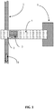
- FIG. 1 shows a device where a cantilevered beam 4 with rigid support 5, whose free end is placed proximal to a current carrying cable 1 and has a magnetostrictive element 2 attached thereto.
- a piezoelectric element 3 is attached to one side of magnetostrictive element 2.
- Maxwell's equations state that it will induce a magnetic field which will cause an axial strain to occur in the magnetostrictive material 2.
- This strain is then transferred to the coupled piezoelectric element that, being piezoelectric, creates an electric potential.
- This voltage is proportional to the strength of the current flow 19 being monitored; however, the current flow induced strain in the magnetostrictive element is extremely small. It is known that the direct-effect dielectric constants of piezoelectric materials is low, so coupling the strain of the magnetostrictive insert to the piezoelectric material substantially reduces an already very small signal to where it becomes negligible and has to resolve noise and other measurement disturbance issues.
- Document US 2005/0134253 A1 discloses a magnetostrictive current sensor comprising a magnetic core and a mechanical prestress arrangement attached to the magnetic core, wherein a magnetostrictive element is held and strained between first and second pole pieces of the prestress arrangement and wherein the magnetic core, the prestress arrangement and the magnetostrictive element together are arranged around a current conductor.
- the magnetostrictive element is disposed and prestressed between first and second pole pieces, wherein the first pole piece has a cross sectional area that decreases in the direction of the magnetic field and towards magnetostrictive element, and wherein the second pole piece has a cross sectional area that increases in the direction of the magnetic field and towards magnetostrictive element.
- magnetostrictive based current sensing device that exhibits minimal signal loss in conversion of induced strain on the magnetostrictive element.
- the present invention presents a novel electrical current sensor capable of both direct current and alternating current measurements that provides for much larger change in resistance output signal per amp flow in the electrical cable or device to be monitored and that ensures that this increased signal strength is temperature independent.
- the invention utilizes a combination of magnetic, magnetostrictive, and resistive strain gauge materials to provide a proportional relationship between electrical current flowing in a cable or device to a change in electrical resistance.
- the present invention features a magnetostrictive current sensor that includes a magnetic core configured to surround a current carrying conductor.
- the magnetic core includes a gap disposed between first and second mounting sections.
- the first mounting section has a cross sectional area that decreases in the direction of a magnetic field induced by the conductor and the second mounting section has a cross sectional area that increases in the direction of the magnetic field.
- Each mounting section includes a generally planar mounting surface being an exterior surface of the magnetic core outside the gap.
- a magnetostrictive element is disposed in a path of a magnetic field and mechanically coupled to the mounting surfaces of the mounting sections outside the gap, the magnetostrictive element having a dimension in the direction of the magnetic field that is larger than the size of the gap in this direction.
- a strain gauge is mechanically coupled to the magnetostrictive element to measure the displacement of the magnetostrictive element induced by the magnetic field.
- the present invention also features a method for manufacturing a magnetostrictive current sensor that includes selecting a hollow magnetic core and forming a gap in that core. First and second mounting sections are then formed in the magnetic core. Each mounting section includes a generally planar mounting surface being an exterior surface of the magnetic core outside the gap. The first mounting section has a cross sectional area that decreases in a direction of an induced magnetic field and the second mounting section has a cross sectional area that increases in direction of the induced magnetic field. A magnetostrictive material is then bonded to the first and second mounting sections outside the gap, the magnetostrictive element having a dimension in the direction of the magnetic field that is larger than the size of the gap in this direction, and a strain gauge is affixed to the magnetostrictive material.
- the present invention is directed to magnetostrictive-based current sensors that measure the change in strain in a magnetostrictive element that results from a change in current flowing through a conductor.
- Electric currents in the current carrying conductor induce a magnetic field according to the 'right hand rule'.
- the magnetic field will be confined by any magnetic material such as ferrite that circumscribes the conductor as to form a closed magnetic circuit.
- a material is magnetostrictive when it engenders a coupling between magnetic energy and mechanical strain, the coupling phenomena being bidirectional. As such, the magnetic field will cause a strain to be generated within the magnetostrictive element in the direction of the magnetic field.
- There is a significant portion of the strain vs. magnetic field response in magnetostrictive materials that is approximately linear.
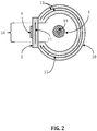
- the invention is generally directed to a magnetostrictive current sensor including a gapped magnetic core 10 configured to circumscribe an electric conductor 1. As shown in FIG. 2 , the current 19 in conductor 1 flowing into the page creates a magnetic field in magnetic core 10, in the direction represented by the arrows 11 that continues through magnetostrictive element 2. Magnetic core 10 includes a gap 14 and a magnetostrictive element 2 mechanically coupled to magnetic core 10 across gap 14. A strain gauge is mechanically coupled to the magnetostrictive element 2.
- a magnetostrictive element 2 is mounted to magnetic core 10 as to bridge gap 14.
- magnetostrictive element 2 is mounted to an exterior surface of magnetic core 10 to provide the geometry of magnetic core 10 at gap 14 and the size of magnetostrictive element 2 are selected to increase the magnetic flux density in the magnetostrictive element 2. Accordingly, the magnetic field 11 now forms a single unbroken path through the magnetic core 10 and magnetostrictive element 2. The magnetic field 11 induces a mechanical displacement in magnetostrictive element 2, which is proportional to the current 19 flowing in conductor 1.
- magnetostrictive element 2 mounting magnetostrictive element 2 to an exterior surface of magnetic core 10 allows magnetostrictive element 2 to have nearly free strain characteristics in its longitudinal direction that aligns with the magnetic field 11 through magnetic core 10. Because magnetostrictive element 2 and magnetic core 10 have similarly high magnetic permeability they provide a low resistance path to contain the magnetic field 11. As such the field will travel from magnetic core 10 through magnetostrictive element 2 rather than through gap 14 thus providing a continuous closed magnetic circuit.
- Increasing the flux density through magnetostrictive element 2 through gap geometry of magnetic core 10 will cause changes in the induced strain of magnetostrictive element 2. That is, the density of magnetic field 11 imparted on the magnetostrictive element 2 controls the ratiometric relationship between the amplitude of strain experienced by magnetic element 2 and the level of current flowing in the conductor 1. Concentration of magnetic field 1 1 in the region of the magnetostrictive element 2 respective to current flowing in the cable 1 provides direct control of current sensor 7 gain. Insufficient magnetic flux density in the magnetostrictive element 2 will cause mechanical strains that are inadequate for accurate measurement.
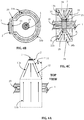
- FIGS. 3A-3C illustrate a high sensitivity embodiment of a current sensor of the present invention.
- a large magnetostrictive element 7 is mechanically coupled to magnetic core 10a, that circumscribes conductor 1, with current 19, flowing into the page.
- Magnetic core 1 includes first and second mounting sections 15 and 16.
- First mounting section 15 has a cross sectional area that decreases in the direction of the magnetic field and the second mounting section 16 has a cross sectional area that increases in the direction of the magnetic field.
- the first and second mounting sections are mirror images of each other.
- Each of the first and second mounting sections includes a generally planar mounting surface 20, 22 to which magnetostrictive element 2 is mechanically coupled.
- Magnetostrictive element 2 may be of sufficient size to cover substantially the entire surface area of generally planar mounting surfaces 20. As illustrated in FIG 3C , the combination of large magnetostrictive element 2 and the geometry of mounting sections 15 and 16 causes a moderate flux density 21 within large magnetostrictive element 2, resulting in a moderate gain for the current sensor.
- FIGS. 4A-4C illustrate a low sensitivity embodiment of a current sensor of the present invention.
- a small magnetostrictive element is mechanically coupled to magnetic core 10a, that circumscribes conductor 1, with current 19, flowing into the page.
- Magnetic core 1 includes first and second mounting sections 15 and 16.
- First mounting section 15 has a cross sectional area that decreases in the direction of the magnetic field and the second mounting section 16 has a cross sectional area that increases in the direction of the magnetic field.
- the first and second mounting sections are mirror images of each other.
- Each of the first and second mounting sections includes a generally planar mounting surface 20, 22 to which magnetostrictive element 2 is mechanically coupled.
- Magnetostrictive element 2 may be of sufficient size to cover substantially the entire surface area of generally planar mounting surfaces 20. As illustrated in FIG 4C , the combination of small magnetostrictive element 2 and the geometry of mounting sections 15 and 16 causes a high flux density 23 within large magnetostrictive element 2, resulting in a high gain for the current sensor.
- a strain gauge 7 is mechanically coupled thereto.
- FIG. 2 shows strain gauge 7 mounted to a generally planar surface of the magnetostrictive element 2 with a high strength adhesive.
- strain gauge 7 may be rigidly bonded to magnetostrictive element 2 as a weak or flexible bond will result in poor coupling between strain gauge 7 and magnetostrictive element 2.
- Strain gauge 7 exhibits a proportional to the strain present within the magnetostrictive element 2, which is indicative of the current flowing in conductor 1.
- the strain gauge 7 can be configured in a Wheatstone bridge configuration in order to compensate for thermal drift present in the strain gauges.
- strain gauge 7 may be of the foil type.
- the invention embodies a method for measuring current using magnetostrictive devices.
- a current carrying wire is passed through a magnetic core such as magnetic core 10 and disposed such that the core surrounds the wire without touching the wire.
- the magnetic core focuses a portion of the magnetic flux from the wire into a small magnetostrictive element such as magnetostrictive element 2.
- the magnetic flux creates a displacement in the magnetostrictive element proportional to the current in the wire.
- the displacement of magnetostrictive element is measured using a strain gauge, such as strain gauge 7 which translates that displacement into resistance which may be used to calculate the current flow in the conductor.
- the invention embodies a method for constructing magnetostrictive material based electrical current sensor.
- An air gap is machined into a closed magnetic core such as gap 14 in magnetic core 10.
- First and second mounting sections are formed in the magnetic core, each mounting section being provided with a generally planar mounting surface.
- a small magnetostrictive element is machined to dimensions slightly larger than the size of the air gap in the magnetic core. After the magnetostrictive element is formed, in some embodiments, is stress annealed in order to improve the general performance (magnetic field vs strain characteristics) of the device.
- a foil-type or Wheatstone bridge strain gauge capable of measuring strains in the range experienced by the magnetostrictive element is selected and bonded to the magnetostrictive element with high-strength adhesive or other attachment method to ensure adequate coupling between the magnetostrictive element strain and the gauge.
- the magnetostrictive element and bonded strain gauge are affixed to the magnetic core with a semi-flexible adhesive, such as in the assembly of FIG. 2 .
- the semi-flexible adhesive allows the assembly to be structurally held in place without severely limiting the motion of the magnetostrictive element.
- Electrical connections are made to the strain gauge, and a current carrying conductor is passed through the magnetic core. As current in the conductor changes amplitude the resistance measured at the output will exhibit proportional changes, hence providing non-contact sensing capability.
- mounting sections 15 and 16 are illustrated as trapezoidal in FIGS 3A-3C and 4A-4C , mounting sections 15 and 16 may comprise many different geometric formations.
- magnetostrictive element 2 may be of various sizes and geometries as long as adequate magnetic flux density is developed within the magnetostrictive element to be accurately measured with the coupled strain gauge.
- the magnetic core may be manufactured from a variety of possible magnetic materials or magnetic composites. The magnetic core so described may be toroidal but can also take other geometries, such as primarily square or ovoid, provided the core substantially encircles the conductor.
Landscapes
- Physics & Mathematics (AREA)
- Engineering & Computer Science (AREA)
- General Physics & Mathematics (AREA)
- Power Engineering (AREA)
- Manufacturing & Machinery (AREA)
- Condensed Matter Physics & Semiconductors (AREA)
- Measurement Of Length, Angles, Or The Like Using Electric Or Magnetic Means (AREA)
- Measuring Instrument Details And Bridges, And Automatic Balancing Devices (AREA)
- Measuring Magnetic Variables (AREA)
Applications Claiming Priority (2)
| Application Number | Priority Date | Filing Date | Title |
|---|---|---|---|
| US201461950815P | 2014-03-10 | 2014-03-10 | |
| PCT/US2015/019778 WO2015138505A1 (en) | 2014-03-10 | 2015-03-10 | Non-contact magnetostrictive current sensor |
Publications (3)
| Publication Number | Publication Date |
|---|---|
| EP3117195A1 EP3117195A1 (en) | 2017-01-18 |
| EP3117195A4 EP3117195A4 (en) | 2018-07-11 |
| EP3117195B1 true EP3117195B1 (en) | 2019-11-06 |
Family
ID=54072344
Family Applications (1)
| Application Number | Title | Priority Date | Filing Date |
|---|---|---|---|
| EP15762271.3A Active EP3117195B1 (en) | 2014-03-10 | 2015-03-10 | Non-contact magnetostrictive current sensor |
Country Status (5)
| Country | Link |
|---|---|
| US (1) | US9983234B2 (enExample) |
| EP (1) | EP3117195B1 (enExample) |
| JP (1) | JP2017510818A (enExample) |
| KR (1) | KR101718679B1 (enExample) |
| WO (1) | WO2015138505A1 (enExample) |
Families Citing this family (7)
| Publication number | Priority date | Publication date | Assignee | Title |
|---|---|---|---|---|
| CN106646293B (zh) * | 2016-10-14 | 2019-02-26 | 东北大学 | 一种高精度大量程非接触式测量磁致应变的装置及方法 |
| CN109425775B (zh) * | 2017-08-25 | 2021-01-26 | 南京理工大学 | 一种采用磁电复合材料的手持式电流传感器 |
| CN108152556B (zh) * | 2018-01-18 | 2023-04-25 | 吉林大学 | 被动激励自供电无线非接触电流传感测量装置及测量方法 |
| CN112345146B (zh) * | 2020-10-23 | 2021-12-31 | 华中科技大学 | 一种基于霍尔元件的三维柔性力传感器及其制备方法 |
| US12196784B1 (en) * | 2022-01-18 | 2025-01-14 | National Technology & Engineering Solutions Of Sandia, Llc | Magnetostrictive current sensor method and system |
| CN115453429B (zh) * | 2022-11-09 | 2023-03-24 | 南方电网数字电网研究院有限公司 | 磁传感器及其制备方法,磁场测量系统 |
| KR102561039B1 (ko) * | 2023-05-19 | 2023-07-28 | 주식회사 에코스 | 저주파 및 고주파 겸용 전류센서, 그것을 이용한 아크검출장치 및 아크차단장치 |
Family Cites Families (16)
| Publication number | Priority date | Publication date | Assignee | Title |
|---|---|---|---|---|
| US3504282A (en) * | 1964-10-14 | 1970-03-31 | Westinghouse Electric Corp | Magnetostrictive current responsive means and transducer means utilizing changes in dimensions of the magnetostrictive means to produce a variable signal which varies with current variations |
| EP0264612B1 (de) * | 1986-09-22 | 1991-12-11 | Siemens Aktiengesellschaft | Stromsensor und Verfahren zum Erfassen des Stromflusses in auszuwertenden Leitern |
| US6781285B1 (en) * | 1994-01-27 | 2004-08-24 | Cymer, Inc. | Packaged strain actuator |
| US6809515B1 (en) * | 1998-07-31 | 2004-10-26 | Spinix Corporation | Passive solid-state magnetic field sensors and applications therefor |
| JP2000088937A (ja) * | 1998-09-17 | 2000-03-31 | Ngk Insulators Ltd | 磁界センサ及びそれを用いた電流検出器 |
| DE10000116A1 (de) * | 2000-01-04 | 2001-07-26 | Epcos Ag | Sensor zur Messung eines Gleichstroms und Messverfahren |
| US20050134253A1 (en) * | 2003-04-10 | 2005-06-23 | Kovanko Thomas E. | Current sensor |
| KR20050055066A (ko) * | 2004-07-14 | 2005-06-10 | (주)에이티에스네트웍스 | 직류 전류 센서 |
| DE102004034723A1 (de) * | 2004-07-17 | 2006-02-09 | Carl Freudenberg Kg | Magnetostriktives Element und dessen Verwendung |
| GB2429782B (en) * | 2005-09-01 | 2010-03-03 | Daniel Peter Bulte | A method and apparatus for measuring the stress or strain of a portion of a ferromagnetic member |
| WO2007110943A1 (ja) * | 2006-03-29 | 2007-10-04 | Loyal Port Company Limited | 磁歪変調型電流センサーとこのセンサーを用いた電流計測方法 |
| US7994780B2 (en) | 2007-09-14 | 2011-08-09 | General Electric Company | System and method for inspection of parts with an eddy current probe |
| CN101654759B (zh) * | 2008-08-19 | 2011-09-21 | 北京麦格东方材料技术有限公司 | 一种磁致伸缩材料及其制备方法 |
| KR101337067B1 (ko) * | 2009-07-02 | 2013-12-05 | 쿠퍼 타이어 앤드 러버 캄파니 | 피에조 자기변형 장치 |
| DE102009054943A1 (de) * | 2009-12-18 | 2011-06-22 | SB LiMotive Company Ltd., Kyonggi | Stromsensor mit Selbsttestfunktion |
| DE102012200556A1 (de) * | 2012-01-16 | 2013-07-18 | Siemens Aktiengesellschaft | Anordnung und Verfahren zur potentialgetrennten Strommessung an einem elektrischen Leiter |
-
2015
- 2015-03-10 WO PCT/US2015/019778 patent/WO2015138505A1/en not_active Ceased
- 2015-03-10 JP JP2016575607A patent/JP2017510818A/ja active Pending
- 2015-03-10 KR KR1020167026667A patent/KR101718679B1/ko not_active Expired - Fee Related
- 2015-03-10 US US15/125,054 patent/US9983234B2/en not_active Expired - Fee Related
- 2015-03-10 EP EP15762271.3A patent/EP3117195B1/en active Active
Non-Patent Citations (1)
| Title |
|---|
| None * |
Also Published As
| Publication number | Publication date |
|---|---|
| JP2017510818A (ja) | 2017-04-13 |
| KR20160118371A (ko) | 2016-10-11 |
| EP3117195A1 (en) | 2017-01-18 |
| WO2015138505A1 (en) | 2015-09-17 |
| EP3117195A4 (en) | 2018-07-11 |
| US9983234B2 (en) | 2018-05-29 |
| KR101718679B1 (ko) | 2017-03-21 |
| US20170074906A1 (en) | 2017-03-16 |
Similar Documents
| Publication | Publication Date | Title |
|---|---|---|
| EP3117195B1 (en) | Non-contact magnetostrictive current sensor | |
| Lopez et al. | Fiber-optic current sensor based on FBG and Terfenol-D with magnetic flux concentration for enhanced sensitivity and linearity | |
| US5831431A (en) | Miniaturized coil arrangement made by planar technology, for the detection of ferromagnetic materials | |
| JP5746019B2 (ja) | 永久又は可変交番磁場循環センサ及び前記センサを使用する電流センサ | |
| JP2017510818A5 (enExample) | ||
| Ou et al. | Self-biased magnetoelectric current sensor based on SrFe12O19/FeCuNbSiB/PZT composite | |
| JP6759965B2 (ja) | 磁気センサ用インダクタンス素子及びこれを備える電流センサ | |
| JP2009210406A (ja) | 電流センサ及び電力量計 | |
| Lu et al. | Zero-biased magnetoelectric composite Fe73. 5Cu1Nb3Si13. 5B9/Ni/Pb (Zr1− x, Tix) O3 for current sensing | |
| JP2020071198A (ja) | 磁気センサ | |
| US20080042636A1 (en) | System and method for current sensing | |
| JP2016148620A (ja) | 電流センサ | |
| JP2016125901A (ja) | 磁界検知装置 | |
| Borole et al. | Design, development, and performance evaluation of GMR-based current sensor for industrial and aerospace applications | |
| US9417294B2 (en) | Current sensors using magnetostrictive material | |
| WO2014116848A1 (en) | Flexible magnetic field sensor | |
| CN108872887B (zh) | 磁场补偿装置 | |
| US20180080961A1 (en) | Isolated dc current and voltage sensor with low crosstalk | |
| KR101300028B1 (ko) | 박막 직교형 플럭스게이트 센서 소자 | |
| JP6151863B2 (ja) | 機械的応力センサ | |
| CN104407311A (zh) | 一种基于光纤光栅的薄片型超磁致伸缩磁场传感器 | |
| JP5678285B2 (ja) | 電流センサ | |
| JP5139822B2 (ja) | 磁界プローブ | |
| CN109683114A (zh) | 一种组装电磁传感器测量系统 | |
| WO2012060069A1 (ja) | 電流センサ |
Legal Events
| Date | Code | Title | Description |
|---|---|---|---|
| STAA | Information on the status of an ep patent application or granted ep patent |
Free format text: STATUS: THE INTERNATIONAL PUBLICATION HAS BEEN MADE |
|
| PUAI | Public reference made under article 153(3) epc to a published international application that has entered the european phase |
Free format text: ORIGINAL CODE: 0009012 |
|
| STAA | Information on the status of an ep patent application or granted ep patent |
Free format text: STATUS: REQUEST FOR EXAMINATION WAS MADE |
|
| 17P | Request for examination filed |
Effective date: 20161007 |
|
| AK | Designated contracting states |
Kind code of ref document: A1 Designated state(s): AL AT BE BG CH CY CZ DE DK EE ES FI FR GB GR HR HU IE IS IT LI LT LU LV MC MK MT NL NO PL PT RO RS SE SI SK SM TR |
|
| AX | Request for extension of the european patent |
Extension state: BA ME |
|
| DAV | Request for validation of the european patent (deleted) | ||
| DAX | Request for extension of the european patent (deleted) | ||
| RIC1 | Information provided on ipc code assigned before grant |
Ipc: G01R 15/18 20060101ALI20180531BHEP Ipc: H01L 41/12 20060101ALI20180531BHEP Ipc: G01L 3/10 20060101AFI20180531BHEP |
|
| A4 | Supplementary search report drawn up and despatched |
Effective date: 20180608 |
|
| RIC1 | Information provided on ipc code assigned before grant |
Ipc: H01L 41/12 20060101ALI20190329BHEP Ipc: G01L 3/10 20060101AFI20190329BHEP Ipc: G01R 33/00 20060101ALI20190329BHEP Ipc: G01L 1/12 20060101ALN20190329BHEP Ipc: G01R 15/18 20060101ALI20190329BHEP Ipc: G01L 1/22 20060101ALN20190329BHEP |
|
| GRAP | Despatch of communication of intention to grant a patent |
Free format text: ORIGINAL CODE: EPIDOSNIGR1 |
|
| STAA | Information on the status of an ep patent application or granted ep patent |
Free format text: STATUS: GRANT OF PATENT IS INTENDED |
|
| RIC1 | Information provided on ipc code assigned before grant |
Ipc: G01R 33/00 20060101ALI20190423BHEP Ipc: H01L 41/12 20060101ALI20190423BHEP Ipc: G01L 1/22 20060101ALN20190423BHEP Ipc: G01L 3/10 20060101AFI20190423BHEP Ipc: G01R 15/18 20060101ALI20190423BHEP Ipc: G01L 1/12 20060101ALN20190423BHEP |
|
| RIC1 | Information provided on ipc code assigned before grant |
Ipc: G01R 33/00 20060101ALI20190430BHEP Ipc: H01L 41/12 20060101ALI20190430BHEP Ipc: G01L 1/22 20060101ALN20190430BHEP Ipc: G01L 1/12 20060101ALN20190430BHEP Ipc: G01L 3/10 20060101AFI20190430BHEP Ipc: G01R 15/18 20060101ALI20190430BHEP |
|
| INTG | Intention to grant announced |
Effective date: 20190520 |
|
| GRAS | Grant fee paid |
Free format text: ORIGINAL CODE: EPIDOSNIGR3 |
|
| GRAA | (expected) grant |
Free format text: ORIGINAL CODE: 0009210 |
|
| STAA | Information on the status of an ep patent application or granted ep patent |
Free format text: STATUS: THE PATENT HAS BEEN GRANTED |
|
| AK | Designated contracting states |
Kind code of ref document: B1 Designated state(s): AL AT BE BG CH CY CZ DE DK EE ES FI FR GB GR HR HU IE IS IT LI LT LU LV MC MK MT NL NO PL PT RO RS SE SI SK SM TR |
|
| REG | Reference to a national code |
Ref country code: GB Ref legal event code: FG4D |
|
| REG | Reference to a national code |
Ref country code: CH Ref legal event code: EP Ref country code: AT Ref legal event code: REF Ref document number: 1199393 Country of ref document: AT Kind code of ref document: T Effective date: 20191115 |
|
| REG | Reference to a national code |
Ref country code: IE Ref legal event code: FG4D |
|
| REG | Reference to a national code |
Ref country code: DE Ref legal event code: R096 Ref document number: 602015041185 Country of ref document: DE |
|
| REG | Reference to a national code |
Ref country code: NL Ref legal event code: MP Effective date: 20191106 |
|
| REG | Reference to a national code |
Ref country code: LT Ref legal event code: MG4D |
|
| PG25 | Lapsed in a contracting state [announced via postgrant information from national office to epo] |
Ref country code: PT Free format text: LAPSE BECAUSE OF FAILURE TO SUBMIT A TRANSLATION OF THE DESCRIPTION OR TO PAY THE FEE WITHIN THE PRESCRIBED TIME-LIMIT Effective date: 20200306 Ref country code: LV Free format text: LAPSE BECAUSE OF FAILURE TO SUBMIT A TRANSLATION OF THE DESCRIPTION OR TO PAY THE FEE WITHIN THE PRESCRIBED TIME-LIMIT Effective date: 20191106 Ref country code: SE Free format text: LAPSE BECAUSE OF FAILURE TO SUBMIT A TRANSLATION OF THE DESCRIPTION OR TO PAY THE FEE WITHIN THE PRESCRIBED TIME-LIMIT Effective date: 20191106 Ref country code: NO Free format text: LAPSE BECAUSE OF FAILURE TO SUBMIT A TRANSLATION OF THE DESCRIPTION OR TO PAY THE FEE WITHIN THE PRESCRIBED TIME-LIMIT Effective date: 20200206 Ref country code: PL Free format text: LAPSE BECAUSE OF FAILURE TO SUBMIT A TRANSLATION OF THE DESCRIPTION OR TO PAY THE FEE WITHIN THE PRESCRIBED TIME-LIMIT Effective date: 20191106 Ref country code: GR Free format text: LAPSE BECAUSE OF FAILURE TO SUBMIT A TRANSLATION OF THE DESCRIPTION OR TO PAY THE FEE WITHIN THE PRESCRIBED TIME-LIMIT Effective date: 20200207 Ref country code: LT Free format text: LAPSE BECAUSE OF FAILURE TO SUBMIT A TRANSLATION OF THE DESCRIPTION OR TO PAY THE FEE WITHIN THE PRESCRIBED TIME-LIMIT Effective date: 20191106 Ref country code: BG Free format text: LAPSE BECAUSE OF FAILURE TO SUBMIT A TRANSLATION OF THE DESCRIPTION OR TO PAY THE FEE WITHIN THE PRESCRIBED TIME-LIMIT Effective date: 20200206 Ref country code: FI Free format text: LAPSE BECAUSE OF FAILURE TO SUBMIT A TRANSLATION OF THE DESCRIPTION OR TO PAY THE FEE WITHIN THE PRESCRIBED TIME-LIMIT Effective date: 20191106 Ref country code: NL Free format text: LAPSE BECAUSE OF FAILURE TO SUBMIT A TRANSLATION OF THE DESCRIPTION OR TO PAY THE FEE WITHIN THE PRESCRIBED TIME-LIMIT Effective date: 20191106 |
|
| PG25 | Lapsed in a contracting state [announced via postgrant information from national office to epo] |
Ref country code: HR Free format text: LAPSE BECAUSE OF FAILURE TO SUBMIT A TRANSLATION OF THE DESCRIPTION OR TO PAY THE FEE WITHIN THE PRESCRIBED TIME-LIMIT Effective date: 20191106 Ref country code: RS Free format text: LAPSE BECAUSE OF FAILURE TO SUBMIT A TRANSLATION OF THE DESCRIPTION OR TO PAY THE FEE WITHIN THE PRESCRIBED TIME-LIMIT Effective date: 20191106 Ref country code: IS Free format text: LAPSE BECAUSE OF FAILURE TO SUBMIT A TRANSLATION OF THE DESCRIPTION OR TO PAY THE FEE WITHIN THE PRESCRIBED TIME-LIMIT Effective date: 20200306 |
|
| PG25 | Lapsed in a contracting state [announced via postgrant information from national office to epo] |
Ref country code: AL Free format text: LAPSE BECAUSE OF FAILURE TO SUBMIT A TRANSLATION OF THE DESCRIPTION OR TO PAY THE FEE WITHIN THE PRESCRIBED TIME-LIMIT Effective date: 20191106 |
|
| PG25 | Lapsed in a contracting state [announced via postgrant information from national office to epo] |
Ref country code: EE Free format text: LAPSE BECAUSE OF FAILURE TO SUBMIT A TRANSLATION OF THE DESCRIPTION OR TO PAY THE FEE WITHIN THE PRESCRIBED TIME-LIMIT Effective date: 20191106 Ref country code: DK Free format text: LAPSE BECAUSE OF FAILURE TO SUBMIT A TRANSLATION OF THE DESCRIPTION OR TO PAY THE FEE WITHIN THE PRESCRIBED TIME-LIMIT Effective date: 20191106 Ref country code: RO Free format text: LAPSE BECAUSE OF FAILURE TO SUBMIT A TRANSLATION OF THE DESCRIPTION OR TO PAY THE FEE WITHIN THE PRESCRIBED TIME-LIMIT Effective date: 20191106 Ref country code: CZ Free format text: LAPSE BECAUSE OF FAILURE TO SUBMIT A TRANSLATION OF THE DESCRIPTION OR TO PAY THE FEE WITHIN THE PRESCRIBED TIME-LIMIT Effective date: 20191106 Ref country code: ES Free format text: LAPSE BECAUSE OF FAILURE TO SUBMIT A TRANSLATION OF THE DESCRIPTION OR TO PAY THE FEE WITHIN THE PRESCRIBED TIME-LIMIT Effective date: 20191106 |
|
| REG | Reference to a national code |
Ref country code: DE Ref legal event code: R097 Ref document number: 602015041185 Country of ref document: DE |
|
| REG | Reference to a national code |
Ref country code: AT Ref legal event code: MK05 Ref document number: 1199393 Country of ref document: AT Kind code of ref document: T Effective date: 20191106 |
|
| PG25 | Lapsed in a contracting state [announced via postgrant information from national office to epo] |
Ref country code: SM Free format text: LAPSE BECAUSE OF FAILURE TO SUBMIT A TRANSLATION OF THE DESCRIPTION OR TO PAY THE FEE WITHIN THE PRESCRIBED TIME-LIMIT Effective date: 20191106 Ref country code: SK Free format text: LAPSE BECAUSE OF FAILURE TO SUBMIT A TRANSLATION OF THE DESCRIPTION OR TO PAY THE FEE WITHIN THE PRESCRIBED TIME-LIMIT Effective date: 20191106 |
|
| PLBE | No opposition filed within time limit |
Free format text: ORIGINAL CODE: 0009261 |
|
| STAA | Information on the status of an ep patent application or granted ep patent |
Free format text: STATUS: NO OPPOSITION FILED WITHIN TIME LIMIT |
|
| REG | Reference to a national code |
Ref country code: DE Ref legal event code: R119 Ref document number: 602015041185 Country of ref document: DE |
|
| 26N | No opposition filed |
Effective date: 20200807 |
|
| PG25 | Lapsed in a contracting state [announced via postgrant information from national office to epo] |
Ref country code: MC Free format text: LAPSE BECAUSE OF FAILURE TO SUBMIT A TRANSLATION OF THE DESCRIPTION OR TO PAY THE FEE WITHIN THE PRESCRIBED TIME-LIMIT Effective date: 20191106 |
|
| PGFP | Annual fee paid to national office [announced via postgrant information from national office to epo] |
Ref country code: GB Payment date: 20200827 Year of fee payment: 6 |
|
| REG | Reference to a national code |
Ref country code: CH Ref legal event code: PL |
|
| PG25 | Lapsed in a contracting state [announced via postgrant information from national office to epo] |
Ref country code: SI Free format text: LAPSE BECAUSE OF FAILURE TO SUBMIT A TRANSLATION OF THE DESCRIPTION OR TO PAY THE FEE WITHIN THE PRESCRIBED TIME-LIMIT Effective date: 20191106 Ref country code: AT Free format text: LAPSE BECAUSE OF FAILURE TO SUBMIT A TRANSLATION OF THE DESCRIPTION OR TO PAY THE FEE WITHIN THE PRESCRIBED TIME-LIMIT Effective date: 20191106 |
|
| REG | Reference to a national code |
Ref country code: BE Ref legal event code: MM Effective date: 20200331 |
|
| PG25 | Lapsed in a contracting state [announced via postgrant information from national office to epo] |
Ref country code: LU Free format text: LAPSE BECAUSE OF NON-PAYMENT OF DUE FEES Effective date: 20200310 |
|
| PG25 | Lapsed in a contracting state [announced via postgrant information from national office to epo] |
Ref country code: LI Free format text: LAPSE BECAUSE OF NON-PAYMENT OF DUE FEES Effective date: 20200331 Ref country code: IT Free format text: LAPSE BECAUSE OF FAILURE TO SUBMIT A TRANSLATION OF THE DESCRIPTION OR TO PAY THE FEE WITHIN THE PRESCRIBED TIME-LIMIT Effective date: 20191106 Ref country code: FR Free format text: LAPSE BECAUSE OF NON-PAYMENT OF DUE FEES Effective date: 20200331 Ref country code: IE Free format text: LAPSE BECAUSE OF NON-PAYMENT OF DUE FEES Effective date: 20200310 Ref country code: CH Free format text: LAPSE BECAUSE OF NON-PAYMENT OF DUE FEES Effective date: 20200331 Ref country code: DE Free format text: LAPSE BECAUSE OF NON-PAYMENT OF DUE FEES Effective date: 20201001 |
|
| PG25 | Lapsed in a contracting state [announced via postgrant information from national office to epo] |
Ref country code: BE Free format text: LAPSE BECAUSE OF NON-PAYMENT OF DUE FEES Effective date: 20200331 |
|
| GBPC | Gb: european patent ceased through non-payment of renewal fee |
Effective date: 20210310 |
|
| PG25 | Lapsed in a contracting state [announced via postgrant information from national office to epo] |
Ref country code: GB Free format text: LAPSE BECAUSE OF NON-PAYMENT OF DUE FEES Effective date: 20210310 |
|
| PG25 | Lapsed in a contracting state [announced via postgrant information from national office to epo] |
Ref country code: TR Free format text: LAPSE BECAUSE OF FAILURE TO SUBMIT A TRANSLATION OF THE DESCRIPTION OR TO PAY THE FEE WITHIN THE PRESCRIBED TIME-LIMIT Effective date: 20191106 Ref country code: MT Free format text: LAPSE BECAUSE OF FAILURE TO SUBMIT A TRANSLATION OF THE DESCRIPTION OR TO PAY THE FEE WITHIN THE PRESCRIBED TIME-LIMIT Effective date: 20191106 Ref country code: CY Free format text: LAPSE BECAUSE OF FAILURE TO SUBMIT A TRANSLATION OF THE DESCRIPTION OR TO PAY THE FEE WITHIN THE PRESCRIBED TIME-LIMIT Effective date: 20191106 |
|
| PG25 | Lapsed in a contracting state [announced via postgrant information from national office to epo] |
Ref country code: MK Free format text: LAPSE BECAUSE OF FAILURE TO SUBMIT A TRANSLATION OF THE DESCRIPTION OR TO PAY THE FEE WITHIN THE PRESCRIBED TIME-LIMIT Effective date: 20191106 |