EP3116563B1 - Flüssigkeitskassette mit kipptoleranter zentrierverrastung sowie blutbehandlungsvorrichtung - Google Patents
Flüssigkeitskassette mit kipptoleranter zentrierverrastung sowie blutbehandlungsvorrichtung Download PDFInfo
- Publication number
- EP3116563B1 EP3116563B1 EP15709507.6A EP15709507A EP3116563B1 EP 3116563 B1 EP3116563 B1 EP 3116563B1 EP 15709507 A EP15709507 A EP 15709507A EP 3116563 B1 EP3116563 B1 EP 3116563B1
- Authority
- EP
- European Patent Office
- Prior art keywords
- centering
- blood treatment
- cassette
- latching
- diameter
- Prior art date
- Legal status (The legal status is an assumption and is not a legal conclusion. Google has not performed a legal analysis and makes no representation as to the accuracy of the status listed.)
- Active
Links
Images









Classifications
-
- A—HUMAN NECESSITIES
- A61—MEDICAL OR VETERINARY SCIENCE; HYGIENE
- A61M—DEVICES FOR INTRODUCING MEDIA INTO, OR ONTO, THE BODY; DEVICES FOR TRANSDUCING BODY MEDIA OR FOR TAKING MEDIA FROM THE BODY; DEVICES FOR PRODUCING OR ENDING SLEEP OR STUPOR
- A61M1/00—Suction or pumping devices for medical purposes; Devices for carrying-off, for treatment of, or for carrying-over, body-liquids; Drainage systems
- A61M1/14—Dialysis systems; Artificial kidneys; Blood oxygenators ; Reciprocating systems for treatment of body fluids, e.g. single needle systems for hemofiltration or pheresis
- A61M1/16—Dialysis systems; Artificial kidneys; Blood oxygenators ; Reciprocating systems for treatment of body fluids, e.g. single needle systems for hemofiltration or pheresis with membranes
-
- A—HUMAN NECESSITIES
- A61—MEDICAL OR VETERINARY SCIENCE; HYGIENE
- A61M—DEVICES FOR INTRODUCING MEDIA INTO, OR ONTO, THE BODY; DEVICES FOR TRANSDUCING BODY MEDIA OR FOR TAKING MEDIA FROM THE BODY; DEVICES FOR PRODUCING OR ENDING SLEEP OR STUPOR
- A61M1/00—Suction or pumping devices for medical purposes; Devices for carrying-off, for treatment of, or for carrying-over, body-liquids; Drainage systems
- A61M1/14—Dialysis systems; Artificial kidneys; Blood oxygenators ; Reciprocating systems for treatment of body fluids, e.g. single needle systems for hemofiltration or pheresis
- A61M1/16—Dialysis systems; Artificial kidneys; Blood oxygenators ; Reciprocating systems for treatment of body fluids, e.g. single needle systems for hemofiltration or pheresis with membranes
- A61M1/1621—Constructional aspects thereof
-
- A—HUMAN NECESSITIES
- A61—MEDICAL OR VETERINARY SCIENCE; HYGIENE
- A61M—DEVICES FOR INTRODUCING MEDIA INTO, OR ONTO, THE BODY; DEVICES FOR TRANSDUCING BODY MEDIA OR FOR TAKING MEDIA FROM THE BODY; DEVICES FOR PRODUCING OR ENDING SLEEP OR STUPOR
- A61M1/00—Suction or pumping devices for medical purposes; Devices for carrying-off, for treatment of, or for carrying-over, body-liquids; Drainage systems
- A61M1/34—Filtering material out of the blood by passing it through a membrane, i.e. hemofiltration or diafiltration
-
- A—HUMAN NECESSITIES
- A61—MEDICAL OR VETERINARY SCIENCE; HYGIENE
- A61M—DEVICES FOR INTRODUCING MEDIA INTO, OR ONTO, THE BODY; DEVICES FOR TRANSDUCING BODY MEDIA OR FOR TAKING MEDIA FROM THE BODY; DEVICES FOR PRODUCING OR ENDING SLEEP OR STUPOR
- A61M1/00—Suction or pumping devices for medical purposes; Devices for carrying-off, for treatment of, or for carrying-over, body-liquids; Drainage systems
- A61M1/36—Other treatment of blood in a by-pass of the natural circulatory system, e.g. temperature adaptation, irradiation ; Extra-corporeal blood circuits
- A61M1/3621—Extra-corporeal blood circuits
- A61M1/3622—Extra-corporeal blood circuits with a cassette forming partially or totally the blood circuit
- A61M1/36222—Details related to the interface between cassette and machine
-
- A—HUMAN NECESSITIES
- A61—MEDICAL OR VETERINARY SCIENCE; HYGIENE
- A61M—DEVICES FOR INTRODUCING MEDIA INTO, OR ONTO, THE BODY; DEVICES FOR TRANSDUCING BODY MEDIA OR FOR TAKING MEDIA FROM THE BODY; DEVICES FOR PRODUCING OR ENDING SLEEP OR STUPOR
- A61M1/00—Suction or pumping devices for medical purposes; Devices for carrying-off, for treatment of, or for carrying-over, body-liquids; Drainage systems
- A61M1/36—Other treatment of blood in a by-pass of the natural circulatory system, e.g. temperature adaptation, irradiation ; Extra-corporeal blood circuits
- A61M1/3621—Extra-corporeal blood circuits
- A61M1/3622—Extra-corporeal blood circuits with a cassette forming partially or totally the blood circuit
- A61M1/36224—Extra-corporeal blood circuits with a cassette forming partially or totally the blood circuit with sensing means or components thereof
-
- A—HUMAN NECESSITIES
- A61—MEDICAL OR VETERINARY SCIENCE; HYGIENE
- A61M—DEVICES FOR INTRODUCING MEDIA INTO, OR ONTO, THE BODY; DEVICES FOR TRANSDUCING BODY MEDIA OR FOR TAKING MEDIA FROM THE BODY; DEVICES FOR PRODUCING OR ENDING SLEEP OR STUPOR
- A61M1/00—Suction or pumping devices for medical purposes; Devices for carrying-off, for treatment of, or for carrying-over, body-liquids; Drainage systems
- A61M1/36—Other treatment of blood in a by-pass of the natural circulatory system, e.g. temperature adaptation, irradiation ; Extra-corporeal blood circuits
- A61M1/3621—Extra-corporeal blood circuits
- A61M1/3622—Extra-corporeal blood circuits with a cassette forming partially or totally the blood circuit
- A61M1/36226—Constructional details of cassettes, e.g. specific details on material or shape
-
- B—PERFORMING OPERATIONS; TRANSPORTING
- B01—PHYSICAL OR CHEMICAL PROCESSES OR APPARATUS IN GENERAL
- B01L—CHEMICAL OR PHYSICAL LABORATORY APPARATUS FOR GENERAL USE
- B01L3/00—Containers or dishes for laboratory use, e.g. laboratory glassware; Droppers
-
- A—HUMAN NECESSITIES
- A61—MEDICAL OR VETERINARY SCIENCE; HYGIENE
- A61M—DEVICES FOR INTRODUCING MEDIA INTO, OR ONTO, THE BODY; DEVICES FOR TRANSDUCING BODY MEDIA OR FOR TAKING MEDIA FROM THE BODY; DEVICES FOR PRODUCING OR ENDING SLEEP OR STUPOR
- A61M2205/00—General characteristics of the apparatus
- A61M2205/12—General characteristics of the apparatus with interchangeable cassettes forming partially or totally the fluid circuit
-
- A—HUMAN NECESSITIES
- A61—MEDICAL OR VETERINARY SCIENCE; HYGIENE
- A61M—DEVICES FOR INTRODUCING MEDIA INTO, OR ONTO, THE BODY; DEVICES FOR TRANSDUCING BODY MEDIA OR FOR TAKING MEDIA FROM THE BODY; DEVICES FOR PRODUCING OR ENDING SLEEP OR STUPOR
- A61M2205/00—General characteristics of the apparatus
- A61M2205/12—General characteristics of the apparatus with interchangeable cassettes forming partially or totally the fluid circuit
- A61M2205/121—General characteristics of the apparatus with interchangeable cassettes forming partially or totally the fluid circuit interface between cassette and base
-
- A—HUMAN NECESSITIES
- A61—MEDICAL OR VETERINARY SCIENCE; HYGIENE
- A61M—DEVICES FOR INTRODUCING MEDIA INTO, OR ONTO, THE BODY; DEVICES FOR TRANSDUCING BODY MEDIA OR FOR TAKING MEDIA FROM THE BODY; DEVICES FOR PRODUCING OR ENDING SLEEP OR STUPOR
- A61M2205/00—General characteristics of the apparatus
- A61M2205/58—Means for facilitating use, e.g. by people with impaired vision
-
- A—HUMAN NECESSITIES
- A61—MEDICAL OR VETERINARY SCIENCE; HYGIENE
- A61M—DEVICES FOR INTRODUCING MEDIA INTO, OR ONTO, THE BODY; DEVICES FOR TRANSDUCING BODY MEDIA OR FOR TAKING MEDIA FROM THE BODY; DEVICES FOR PRODUCING OR ENDING SLEEP OR STUPOR
- A61M2209/00—Ancillary equipment
- A61M2209/08—Supports for equipment
-
- B—PERFORMING OPERATIONS; TRANSPORTING
- B01—PHYSICAL OR CHEMICAL PROCESSES OR APPARATUS IN GENERAL
- B01L—CHEMICAL OR PHYSICAL LABORATORY APPARATUS FOR GENERAL USE
- B01L2200/00—Solutions for specific problems relating to chemical or physical laboratory apparatus
- B01L2200/02—Adapting objects or devices to another
- B01L2200/025—Align devices or objects to ensure defined positions relative to each other
-
- B—PERFORMING OPERATIONS; TRANSPORTING
- B01—PHYSICAL OR CHEMICAL PROCESSES OR APPARATUS IN GENERAL
- B01L—CHEMICAL OR PHYSICAL LABORATORY APPARATUS FOR GENERAL USE
- B01L2200/00—Solutions for specific problems relating to chemical or physical laboratory apparatus
- B01L2200/02—Adapting objects or devices to another
- B01L2200/026—Fluid interfacing between devices or objects, e.g. connectors, inlet details
Definitions
- the present invention relates to a fluid cartridge according to the preamble of claim 1 and to a blood treatment device according to the preamble of claim 10.
- Disposable parts systems are increasingly being used in medical or laboratory technology as compact medical functional devices, such as cassette systems or blood treatment cassettes, in which liquids and gases, in particular medical fluids and blood, are guided in channels and chambers. If they are intended for single use, it is called cassette disposables or disposable cassettes.
- the hard part is usually made of an injection-molded material such as PE, PP, PA, ABS, PMMA, PC or PVC. In it, for example, hose connections, connectors, chambers, channels and centering devices are configured.
- the blood treatment cassette When used in the blood treatment device, the blood treatment cassette is inserted between a door and an actuator / sensor unit of the blood treatment device, and the door is then closed by bringing it into a so-called pressed position in which the film is pressed against the hard part and the Blood treatment cassette with the film spatially defined is coupled to the actuator sensor mat of the actuator-sensor unit.
- Actuators also referred to herein as actuators
- actuators incorporated into the actuator sensor mat and actuator sensor plate (or unit)
- Sensor side can exercise movements through the film, which, for example, pump or valve functions can be realized.
- properties of fluids flowing through the blood treatment cassette can be measured by means of at least one sensor optionally provided in the actuator sensor plate. From the US 2013/0248629 A1 are known devices for supplying medical fluids.
- a sealing device for sealing a volume of a medical treatment arrangement against another volume and arrangement and method are known from DE 2009 012 632 A1 known.
- Coupling device, connector, medical functional device and treatment device are in the DE 10 2010 032 181 A1 disclosed.
- An object of the invention may be to propose a further medical liquid cassette (cassette for receiving medical fluids), in particular a blood treatment cassette, with a device for centering the medical liquid cassette (in the following: liquid cassette) on the blood treatment device. Furthermore, a blood treatment device for using the liquid cassette is to be specified.
- the object can be achieved by a liquid cassette having the features of claim 1, further by a blood treatment apparatus having the features of claim 10.
- a liquid cassette in particular blood treatment cassette, is proposed, with a cassette body designed as a hard part.
- the blood treatment cassette may optionally comprise a foil. If a film is provided, then it is connected to the hard part, covers the hard part at least in sections.
- the hard part has at least a first centering device and a second centering device. They are preferred disposed opposite or associated with the first and second sides of the blood treatment cassette.
- a blood treatment device configured for connection to a blood treatment cassette according to the invention, which has an actuator-sensor plate with at least one actuator.
- the latter is configured for interaction between actuators and / or sensors of the blood treatment device with devices of the blood treatment cassette.
- Embodiments of the invention may include one or more of the features listed above and / or below in any combination.
- the blood treatment cassette has at least one, preferably circumferential, edge web with an end face on a front and / or rear side thereof.
- the end face lies in a plane which is preferably parallel to a main extension plane of the blood treatment cassette.
- the end face is preferably planar in some exemplary embodiments of the invention. In these embodiments, therefore, it lies exclusively in one plane.
- the principal plane of extension in some exemplary embodiments of the invention, is parallel to a plane spanned by the foil, if present, or main plane of extension.
- the blood treatment cassette is designed to be connected in the intended use of the blood treatment cassette in the main extension plane in a translationally play-free manner with a first centering pin of a blood treatment device.
- the second centering device is designed in this embodiment, in order to Proper use of the blood treatment cassette about an axis, which is preferably perpendicular or substantially perpendicular to the main extension plane, rotationally free of play connected to a second Zentrierrastpin the blood treatment device.
- the first centering device has centering facets whose centering surfaces extend, at least in sections, in each case in a plane preferably perpendicular or substantially perpendicular to the main extension plane of the blood treatment cassette.
- the centering facets touch the first centering pin at least in sections, and preferably tangentially.
- a centering facet is at least partially a portion of an insertion portion, an insertion slope, or an insertion funnel of a centering device, wherein the insertion portion, the insertion slope, or the insertion funnel is for receiving a portion of the centering peg.
- This section ie the centering facet itself, has-for example or preferably in at least one spatial direction or in two mutually perpendicular spatial directions-a different curvature and / or inclination than other sections of the insertion section, the insertion bevel or the insertion funnel or as adjacent, for example at the same height (approximately with respect to an insertion direction or depth) lying, portions of the insertion, the insertion or the insertion funnel.
- a centering facet is a portion of the insertion funnel or insert portion in which the portion or funnel has a larger inner diameter or greater clearance than at other portions of the portion or funnel adjacent to the centering facet.
- the insertion funnel or insertion section has, at least in sections, a more or less pronounced funnel shape.
- the insertion funnel opens towards an exterior of the centering device and / or becomes narrower in the insertion direction of the centering locking pin.
- the insertion funnel, the insertion section or the insertion bevel may have an inlet or edge rounded inwards and / or outwards (relative to the diameter of the insertion funnel or of the insertion section, in each case in the region of the inlet).
- the rounding may be circumferential or present only in portions of the edge.
- a locking edge is configured in some exemplary embodiments of the invention as a contact surface similar to a biting surface of a pair of pliers.
- the first centering device has at least one lever edge web. This may be located at the outermost edge of the first centering device or laterally bounded with respect to the center of the blood treatment cassette.
- the first centering device and / or the second centering device each have at least one actuator-sensor-side insertion bevel or at least one insertion funnel for receiving a portion of a centering-locking pin.
- the first and / or the second centering device have at least two latching tongues with at least one latching edge each.
- the latching edge runs - preferably completely, substantially or at least in sections - in a plane parallel to the main extension plane of the blood treatment cassette.
- the passage bore or opening of the second centering device substantially or completely in the form of a rectangle or a slot.
- the longitudinal axis of the second centering device is oriented toward the center of the passage bore or opening of the first centering device.
- the blood treatment device is connected to a blood treatment cassette according to the invention.
- a first centering pin and / or a second centering pin have a centering diameter. He also has a locking diameter, which is less than the centering diameter.
- a circumferential section of the centering locking pin lying between the centering diameter and the one locking diameter merges into the centering diameter and / or the locking diameter by means of a rounded transition.
- the first Zentrierrastpin and / or the second Zentrierrastpin a flat end face.
- the first Zentrierrastpin and / or the second Zentrierrastpin a rounded end face edge.
- the front edge is that edge at which the end surface merges into the lateral surface or the circumferential surface of the Zentrierrastpins.
- the first centering pin and / or the second centering pin have a centering height which is in the range of 0.1 to 0.5 times their centering diameter.
- the centering height is the free height or height at which the Zentrierrastpin - preferably with or only with its centering diameter, but not with its entire height - rises above the level of the actuator sensor mat surrounding it.
- the centering diameter is the diameter of the Zentrierrastpins, which the centering function of Centering pins takes over.
- the centering diameter may be the widest diameter of the portion of the centering pint protruding beyond the actuator sensor mat. It may be the diameter of that portion of the Zentrierrastpins, which adjoins this immediately above the actuator sensor mat.
- the first centering device and / or the second centering device serve not only for centering but also for latching the blood treatment cassette to the blood treatment device.
- the machine door preferably rests on door-side (ie machine-side) support webs and on the flat end faces of the latching tongues.
- At least one centering detent pin is configured symmetrically and / or as a cylinder. He has in these embodiments, a centering cylinder.
- all the bearing surfaces of the machine door which contact the blood treatment cassette are parallel to the main extension plane of the cassette. This advantageously ensures a sole centering of the cassette on the Zentrierrastpins.
- the centering pegs are configured to be in communication with the flat and correspondingly generous dimensioned end faces of the blood treatment cassette around both centering around an ergonomically favorable allowable lateral offset of preferably 0.5 to 2.5 times the centering diameter to be limited or limited thereto.
- the initial allowable lateral offset of the blood processing cassette prior to engaging respective introducer shanks is preferably 0.1 to 0.2 times the centering diameter.
- one of the centering pins is threaded into one of the centering devices - after completion of one-sided threading - so far that one or more of the locking edges of the centering device rest against the rounded end face edges of the centering pin, while the other centering pin has not yet begun threading it did not complete.
- the blood treatment cassette is a disposable or disposable article.
- the blood treatment cassette and / or the blood treatment device are configured for apheresis, hemodialysis, hemofiltration, hemodiafiltration, hemo-ultrafiltration, and the like.
- the achievable advantages may include the zero-backlash and reproducible alignment of the blood treatment cassette regardless of its manufacturing tolerances and the tolerances of the blood treatment device.
- the blood treatment cassette may be gripped at arbitrary positions during setup and during disassembly, and that despite the different tilting constellations, each phase of the up and disarming process proceeds properly or as desired. A faulty upgrading or disassembly is therefore not possible in many embodiments according to the invention.
- tilting material tensions of the blood treatment cassette can be limited to values well below the threshold above which destruction of the blood treatment cassette can occur; This also applies to a jerky disassembly.
- an ergonomically simple manual assembly and disarming of the blood treatment cassette to the blood treatment device can be ensured while at the same time backlash-free centering and a non-destructive arrangement. Impermissibly strong tilting and resulting material stresses can be ruled out.
- the operator may grab the blood treatment cassette anywhere and strain. Also, the order of locking and unlocking may take place arbitrarily.
- the zero backlash and maximum centering accuracy is advantageously achieved first by the provision of two spaced apart centering, the first centering defines the zero point of translational displacement and the second centering, which is preferably slot-like, determines the angular orientation and thereby the global dimensional tolerances between blood treatment device and Balancing blood treatment cassette.
- the backlash is created by the local application of facet centering. Local here means that it is about the tolerance assignment of the centering diameter of Zentrierrastpins to the faceted centering holes or openings of the centering (with significantly lower tolerances than the distance between the two centering).
- the (boundary) clearance, height and diameter ratios determined according to the invention advantageously ensure that all possible tiltings between the blood treatment cartridge and the blood treatment device remain in angular ranges that are below the critical tilt angles.
- the selected centering and the tilted arrangement of Zentrierfacetten the second centering ensures that in conjunction with the reduced Aushebel bin at tilting unilateral disengagement in the most unfavorable possible Verkippraum the tilt critical angular range can not be achieved advantageous.
- a machine door and with her taking place compression of the blood treatment cassette against the actuator-sensor unit are not essential to ensure the illustrated inventive features.
- the play-free centering and locking on the centering pins can be sufficient for a reliable support and positioning of the blood treatment cassette even when using blood treatment devices that have no machine door.
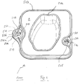
- Fig. 1 shows a blood treatment cassette 1000 according to the invention, also referred to herein as cassette 1000, in a perspective plan view on the main extension plane thereof. Shown is the coupling of the cassette 1000 with the in Fig. 1 Not shown actuator-sensor unit 514 of in Fig. 1 also not shown blood treatment device 5000, herein also referred to as machine 5000, serving side, which is referred to here as the back or docking side.
- the blood treatment cassette 1000 has a hard part 1, which is optionally manufactured by thermoplastic injection molding. Its modulus of elasticity is preferably between 600 and 2800 N / mm 2 . In use, the hard part 1 is preferably at least partially by means of a in Fig. 1 not shown foil 3 covered.
- the cassette 1000 in addition to elements that are relevant for the blood treatment, such as chamber boundaries 502, at least one - preferably peripheral - edge web 503 on.
- the latter serves in addition to the sealing of portions of the cassette 1000 with respect to in Fig. 1 not shown machine 5000 and the orientation of the cassette 1000 on the machine 5000 with the aim to contribute to a flat system of the cassette 1000 on the machine 5000, also as Abhebelsteg in the disassembly of the cassette 1000th
- the cassette 1000 further includes a first centering device 504 which, in addition to centering the cassette 1000 relative to the machine 5000, may also serve to temporarily secure the cassette 1000 to the machine 5000.
- the first centering device 504 may be referred to as the translationally play-free origin of the orientation of the cassette 1000. It may, as well as the second centering device 505 described below, be configured as Zentrierrasthülse.
- the first centering device 504 is preferably arranged on the edge or on one side of the cassette 1000. It is preferably in the middle of a page or long side, so centrally located. Preferably, it is arranged at an identical or comparable distance in each case to alignment-critical structures of the cassette 1000 (for example sensor and valve points) which are relevant for the blood treatment.
- a second centering device 505 is designed as a rotary backlash-aligning Zentrierrasthggse on the cassette 1000th intended. It preferably lies on one side or longitudinal side of the cassette 1000, which lies opposite that side on which the first centering device 504 lies. In this way, an advantageously large distance between the first centering device 504 and the second centering device 505 is achieved.
- the first centering device 504 has a take-off edge web 506. It also has at least one insertion bevel facing towards the actuator-sensor unit (ie, the insertion bevel opens towards the actuator-sensor unit, for example opens like a funnel) or such an insertion funnel 507. With the insertion funnel 507, the rounded edge of the first or second centering device 504, 505 is thus designated in this exemplary embodiment. It serves for coarse pre-centering of the cassette 1000.
- the Abhebel-edge web 506 is a stiffened support surface (no support line and no support point but-surface), which initiates the resulting forces in the machine-side actuator sensor mat 515 when tilting the cartridge when levering and disengaging to the actuator sensor mat 515 to protect against excessive wear.
- the Abhebel-edge web 506 may be spaced in the main plane of extension of the edge of the centering and / or increased, so that due to the bending moment during tilting and levering and disengagement of the cartridge required for disengagement, axial force component occurs.
- the Abhebel-edge web 506 can, as in Fig. 1 1, a bevel facet 506a may be provided which may be on a side surface of the peel edge ridge 506.
- the Abhebel-edge web 506 may further, as in Fig. 1b 1, a rounded edge 506b is located between the bevel facet 506a and a generally horizontal end face 506c of the peel edge ridge 506.
- the Abhebel edge web 506 is also from the enlarged views in Fig. 1a and 1b forth, where Fig. 1a an enlargement of the first centering device 504 in the view of Fig. 1 shows, and where Fig. 1b an enlargement of the Abhebel edge web 506 of Fig. 1 or the Fig. 1a shows.
- Fig. 1c an enlargement of a section Fig. 1 , which for the representation Fig. 1c is cut, facing from the opposite direction.
- Fig. 1c shows only three of the four total distributed over the circumference of the insertion funnel 507 Zentrierfacetten 509 of the first centering device 504 due to the cut.
- the centering facets 509 are at least partially or in their upper part part of the insertion funnel 507. They are arranged above the locking edge 512.
- the first centering device 504 has four centering facets 509 which second centering device 505, however, only two, as well as in Fig. 1 can be seen.
- the centering facets 509 may extend in a plane perpendicular to the main extension plane of the cassette 1000 (at least locally or in sections).
- the centering facets 509 are used for local or point contact with the respective Zentrierrastpin 517, 518. They centering the Zentrierrastpins 517, 518 thus translational or centering each with respect to a translational displacement.
- the centering facets 509 may, for example, directly adjoin or be part of the respective insertion funnel 507, as stated above. They extend, for example, only between approximately 5 and 30% of the centering diameter 522 in the axial direction along the axis of rotation of the Zentrierrastpins 517, 518 or the Zentrierrasthülsen or perpendicular to the film plane or the main extension plane before the end of the axial overlap with the centering (characterized by Centering diameter and centering height) of Zentrierrastpins 517, 518) is reached.
- the centering facets 509 extend, for example, by about 10 to 80% of the centering diameter 522.
- one or all of the centering facets 509 may be wider at the top than at the bottom.
- Centering facets 509 or their extension axes can be arranged in planes perpendicular or substantially perpendicular to the film plane or substantially parallel to the centering pin symmetry axis.
- the facet surfaces thus result in small areas, each of which can be arranged substantially perpendicular to the film plane.
- the line contact may be a line, for example, a value in the range of 0 to 30% of the centering diameter 522.
- This short contact line preferably extends substantially parallel to the axis of symmetry of the centering pin 517, 518.
- the first centering device 504 preferably has four first facet surfaces 509 (but it could also be three, five, six or more facet surfaces).
- the second centering device 505 has in the present example two (exactly two, because of the deliberately deliberately omitted translational attachment along the connection axis between the two centering devices 504, 505).
- the exactly two facet surfaces 509 face each other in parallel and in mirror image with respect to a plane which is arranged substantially perpendicular to the film plane and thereby contains the connecting line between the two centering devices 504 and 505 and both axes of symmetry of the two centering pegs 517, 518 ,
- two facet surfaces each lie parallel and mirror-image with respect to a plane which is arranged substantially at right angles to the film plane (ie contains the axis of symmetry of the first centering device 504).
- the square is here additionally aligned again at the connecting line between the two centering devices.
- the orientation may be such that the connecting line intersects square sides at right angles.
- the square shape and this alignment need not be in order to fulfill the proper function as translational play-free alignment zero point. Rather, the centering hole shape of a triangle, pentagon or hexagon with any rotational alignment is possible and encompassed by the present invention.
- the centering facets 509 may be part of the insertion funnel 507. They are, at least in sections, advantageously in an upper region of the insertion funnel 507, see also the enlarged view in Fig. 1c ,
- Fig. 1c is the side of the cassette 1000, which in use to the actuator-sensor mat 516 shows the top.
- the side of the cassette 1000 or the side of the cassette 1000, which is in use to the machine door, is at the bottom.
- the centering facets are 509 in certain exemplary embodiments above the locking edge (s) 512. Above this is to be understood as closer to the actuator sensor mat 516 out, below as further to the front of the cassette out or to understand the machine door.
- the latching edges 512 are configured in preferred, exemplary embodiments according to the invention as straight or curved edges. This embodiment allows approximately a point contact with a locking diameter 521 of a Fig. 1 Not shown Zentrierrastpins 517, 518, in contrast to an elongated or (large) surface contact.
- first centering device 504 and / or the second centering device 505 in certain exemplary embodiments of the invention not only center but also contribute to or contribute to the latching of the cassette 1000 to the machine 5000, in such embodiments they may also be referred to as centering detents.
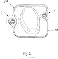
- Fig. 2 shows the cassette 1000 of Fig. 1 in a perspective plan view of the door side.
- the door side can be optionally pressed by means of an in Fig. 2 not shown machine door 524 serve. It lies opposite the coupling side and can be called the front side.
- Fig. 2 shows another - here again only optionally circumferentially shown - edge bar 508.
- This can be described as multifunctional, since it not only serves as a surface (preferably in a plane) for the transmission of the compression effect by means of the machine door 524, but also for stiffening the cassette 1000 and for stiffening connection of the first centering device 504 and / or the second centering device 505. It can also the transmission of the up and Abrüst member and ways of those (Any) places at which the user touches the cassette 1000 for disarming and from which starting forces are transmitted via the first centering device 504 and / or the second centering device 505 in the cassette 1000 and on the Zentrierrastpins 517, 518 serve.
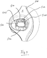
- Fig. 3 shows the detail view G of Fig. 2 .
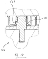
- Fig. 4 shows the detail view F of Fig. 2 .
- the reference numeral 510 designates latching tongues in the figures, which are parts of the first centering device 504 and / or the second centering device 505.
- Per centering device 504, 505 preferably at least two locking tongues 510 are provided, preferably opposite each other.
- the latching tongues 510 can be designed elastically bendable for the intended use. They can be separated from one another by cuts 511, which contributes to the targeted flexing of the locking tongues 510.
- Each latching tongue 510 has at least or exactly one latching edge 512. This extends in a first plane parallel to the main extension plane preferably locally straight in a plane parallel to the main extension plane of the cassette 1000 to allow a displacement relative to the Zentrierrastpins 517, 518 without changing the detent-holding force, and also a priority of the centering of the Zentrierfacetten 509 guarantee.
- the locking edge 512 is in preferred embodiments according to the invention in a second plane which is perpendicular to Main extension plane is, a curved edge or has such. This shape allows a line contact with the likewise curved grooves of the Zentrierrastpins 517, 518 and thus causes minimization of friction during up and Abrüst operations.
- Fig. 5 shows the actuator-sensor unit 514 of the machine 5000 in a perspective plan view of the main extension plane of the former.
- Fig. 6 is the detail view H off Fig. 5 in perspective.
- Fig. 7 is the detail view H off Fig. 5 on average.
- Reference numeral 514 in the figures refers to the actuator-sensor unit 514 of the machine 5000, where 515 denotes the actuator-sensor mat of the unit 514.
- the actuator-sensor mat 515 is only provided as an option and likewise designed to be flat on the cassette 1000, for preferably even coupling.
- 516 denotes the actuator-sensor plate, it is rigid reference body and anchoring ground for the first and the second Zentrierrastpin 517 and 518, respectively.
- the first Zentrierrastpin 517 is provided for locking with the first centering device 504, while the second Zentrierrastpin 518 is provided for locking with the second centering device 505.
- the limitation of the tilting advantageously results from the fact that the tilting angle steadily increases during the tilting expansion movement; because of the same time As a result, the centering device is displaced relative to the centering pin in parallel with the increase in the tilting angle. Since the centering height 523 of Zentrierrastpins 517, 518 is limited, the corresponding centering 504, 505 comes in a non-critical with respect to the canting angle with low tilt angle in the centering facets 509 disengaged from the centering 522 Zentrierrastpins 517, 518th
- Fig. 8 shows in plan view the cassette and sections of the machine in the upgraded state without an already purely optional machine door.
- Fig. 9 shows a section along the line HH of Fig. 8 ; is added to the Fig. 8 the optional machine door 524; shown is the compressed state.
- the optional machine door 524 is for pressing the cassette 1000 and aligning it in a plane should the cassette 1000 be wound once or bent.
- the alignment takes place on the actuator-sensor unit 514 and by means of the peripheral edge web 508 and possibly further, optional, flat support zones 525 and 526.
- the cassette 1000 abuts against the actuator-sensor mat 515 during the blood treatment by means of frictional engagement. This ensures that the centering position of the cartridge 1000 is maintained even when mechanical or fluidic forces are applied to the cartridge 1000 or connecting hoses connected thereto.
- all bearing surfaces of the machine door 524 that contact the cartridge 1000 are parallel to the main plane of extension of the cartridge 1000. This advantageously ensures sole centering of the cartridge 1000 via the centering pegs 517 and 518.
- Fig. 10 shows the first centering device 504 in detail along the line SS of Fig. 8 on average.
- Fig. 11 shows the second centering device 505 in detail along the line KK of Fig. 8 on average.
- Fig. 12 and Fig. 13 show detailed views of the first and second centering device 504 and 505 along the line HH of Fig. 8 on average.
- Fig. 10 shows the first centering device 504 in a cutting direction SS Fig. 8 in which the two short opposing contact lines or line contact sections 527 are each of equal length and comparatively long (since the lever edge distance to the cassette edge webs at the top and bottom is very long).
- Fig. 11 shows a cut to the Fig. 10 analogue cut. That too Fig. 10 This can also be said Fig. 11 hold true.
- Fig. 12 shows the section through the first centering device along the section HH, which is particularly unfavorably affected by the initiation of larger tilts when up and disassembling, as in the Fig. 20 to 23 shown.
- Fig. 12 If one sees a left, shorter line contact section 527 on the left, which is characterized by the inverting anticipated pre-tilted arrangement of Zentrierengstelle Fig. 26 is also located farther away from the actuator sensor mat 515 than the right longer line contact portion 527 on the right.
- the line contact portions 527 or line pieces preferably dot-dot the centering pins 517, 518 at the centering diameter 522, see also Fig. 24 ,
- the tolerance situation of the passage width between the line contact sections 527 and the centering diameters 522 of Zentrierrastpins 517, 518 is preferably selected so that always backlash (ie no game) is given, from the play-free system to complete Zentrierverrastung the cassette 1000. Due to the punctiform or short-line installation of all (here: four) centering facets 509 of the first centering device and the (here: two) centering facets 509 of the second centering device.
- Zentrierrastpin 517, 518 pressed with the comparatively softer Zentrierfacetten 509 wherein the diameter of the Zentrierrastpins 517, 518 measured at the distance between opposite Zentrierfacetten preferably has an excess, deforms the softer surface at least partially elastic and partially plastic.
- a point contact becomes a circular or oval contact surface and from a line contact a contact surface. The freedom from play in the locked state remains on the one hand always guaranteed.
- the compression forces and thus the frictional forces during disassembly are sufficiently low due to the low modulus of elasticity of the thermoplastic (for example, 1800 N / mm 2) and due to the partial plastic deformation, so that the material does not break when tilted.
- the longitudinal axis of the second centering device 505 is aligned in the direction of the center of the passage bore or opening for the first centering device 504 in order to limit the rotation possibility of the cassette 1000 maximum. At the same time, the longitudinal axis approximately in the direction of the shortest distance to the edge web 508 of the cassette 1000th
- the cuts or slots 511 between the locking tongues 510 are preferably also arranged symmetrically to the connecting axis or line between the first and the second centering device 504, 505 and serve to increase the tilting freedom of movement.
- Fig. 14 shows a first step of the Aufrüstvorgangs, attaching the cartridge 1000.
- the reference numeral 3 denotes the film.
- Fig. 15 shows the second step of the upgrade, the beginning of threading.
- Fig. 16 shows the third step of the upgrade process, the one-sided completion of threading.
- Fig. 17 shows the fourth step of the upgrade process, the two-sided completion of Einfädelept.
- Fig. 18 shows the fifth step of the upgrade process, the one-sided completion of a Zentrierverrastung.
- Fig. 19 shows the sixth step of the upgrade process, the two-sided completion of Zentierverrastept.
- the flat end faces of the centering pins 517, 518 in conjunction with the flat and correspondingly generously dimensioned flat end faces of the cassette 1000 around both centering devices 504, 505 allow an ergonomically acceptable lateral offset 530 of FIG preferably 0.5 to 2.5 times the centering diameter 522 during manual application of the cassette 1000 without risk of damage.
- Zentrierrastpin-Stirn' Due to the selected distance between the centering devices 517, 518 in conjunction with the height difference between the total height of a Zentrierrastpins 517, 518 and the centering 523 is a maximum angular misalignment 532 between the main plane of extension of the cassette 1000 and the main plane of extension of the machine 5000 about 1 ° - 3 ° , In connection with the geometrical designs 'rounded Zentrierrastpin-Stirn', locking diameter 'smaller than centering diameter' and 'insertion bevels of the centering' tilting and thus movement impediments or material overloads are prevented at any running threading.
- both centering devices 504, 505 are inserted into the centering pegs 517, 518 so far that a distance 533 of the two main extension planes (of cassette 1000 on the one hand and actuator-sensor-mat 515 on the other hand) only amounts to approximately 0.02 to 0 , 04 times the centering distance.
- a distance 533 of the two main extension planes (of cassette 1000 on the one hand and actuator-sensor-mat 515 on the other hand) only amounts to approximately 0.02 to 0 , 04 times the centering distance.
- an angular misalignment 534 of more than about 1.5 degrees can not be achieved.
- This slight angular misalignment 534 in conjunction with the choice of material and geometry, does not yet cause jamming forces which lead to overloading of the material of the cassette 1000.
- these canting forces do not exceed the maximum desired latching force of approximately 50 N in all tolerance positions of the dimensions.
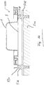
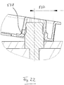
- Fig. 20 shows a critical moment of disengagement on the second centering device 505 during the Abrüstvorgangs.
- Fig. 21 shows a critical moment of disengagement on the first centering device 504 during the Abrüstvorgangs.
- Fig. 22 shows in detail the section O of Fig. 20 .
- Fig. 23 shows in detail the section P of Fig. 21 .
- At the first centering device 504 prevents the tilted assembly 541 of Zentrier devisgangsbohrung in connection with the cuts 511 between the locking tongues 510 and in conjunction with the Aushebel-edge distance 537 and the height and diameter ratios reaching the tilting situation 539.
- An optionally existing, smooth-shaped tongue 540 can not cause critical canting, since it is bendable like the locking tongues 510.
- Fig. 24 shows in a schematic representation of the centering devices 504, 505 with purely exemplary dimensioning and Zentrierrastpins recorded therein.
- Fig. 25 shows in a schematic representation of the tilting with omitted locking tongues 510th
- Fig. 26 shows in a schematic representation of the first centering device 504 in the upgraded position.
- Fig. 27 shows in a schematic representation of the second centering device 505 at the critical moment of Ausrastens.
- the angle of attack 541 of the passage bore or opening of the first centering device 504 is advantageously about 9 ° to 14 °.
- the moment of disengaging the latching tongues 510 substantially coincides with the disengaging 539 of the centering facets 509 with the centering diameter 522 of the Zentrierrastpins 517, 518, wherein projected onto the machine plane distance of the two facets involved during the Aushebel-Abrüst Movement continuously enlarged and always larger than the centering diameter 522 remains.
Landscapes
- Health & Medical Sciences (AREA)
- Heart & Thoracic Surgery (AREA)
- Vascular Medicine (AREA)
- Animal Behavior & Ethology (AREA)
- Hematology (AREA)
- Veterinary Medicine (AREA)
- Public Health (AREA)
- Engineering & Computer Science (AREA)
- Anesthesiology (AREA)
- Biomedical Technology (AREA)
- General Health & Medical Sciences (AREA)
- Life Sciences & Earth Sciences (AREA)
- Cardiology (AREA)
- Urology & Nephrology (AREA)
- Emergency Medicine (AREA)
- Clinical Laboratory Science (AREA)
- Chemical & Material Sciences (AREA)
- Chemical Kinetics & Catalysis (AREA)
- External Artificial Organs (AREA)
Priority Applications (1)
| Application Number | Priority Date | Filing Date | Title |
|---|---|---|---|
| PL15709507T PL3116563T3 (pl) | 2014-03-14 | 2015-03-13 | Kaseta na ciecz z zatrzaskiem środkowym z tolerancją przechyłu i urządzenie do przetaczania krwi |
Applications Claiming Priority (2)
| Application Number | Priority Date | Filing Date | Title |
|---|---|---|---|
| DE102014103492.9A DE102014103492A1 (de) | 2014-03-14 | 2014-03-14 | Flüssigkeitskassette mit kipptoleranter Zentrierverrastung sowie Blutbehandlungsvorrichtung |
| PCT/EP2015/055299 WO2015136077A1 (de) | 2014-03-14 | 2015-03-13 | Flüssigkeitskassette mit kipptoleranter zentrierverrastung sowie blutbehandlungsvorrichtung |
Publications (2)
| Publication Number | Publication Date |
|---|---|
| EP3116563A1 EP3116563A1 (de) | 2017-01-18 |
| EP3116563B1 true EP3116563B1 (de) | 2019-01-16 |
Family
ID=52669623
Family Applications (1)
| Application Number | Title | Priority Date | Filing Date |
|---|---|---|---|
| EP15709507.6A Active EP3116563B1 (de) | 2014-03-14 | 2015-03-13 | Flüssigkeitskassette mit kipptoleranter zentrierverrastung sowie blutbehandlungsvorrichtung |
Country Status (14)
| Country | Link |
|---|---|
| US (2) | US10471196B2 (pl) |
| EP (1) | EP3116563B1 (pl) |
| JP (1) | JP6594890B2 (pl) |
| KR (1) | KR102433088B1 (pl) |
| CN (1) | CN106102792B (pl) |
| AU (1) | AU2015228756B2 (pl) |
| BR (1) | BR112016020883B1 (pl) |
| CA (1) | CA2941195C (pl) |
| DE (1) | DE102014103492A1 (pl) |
| ES (1) | ES2720349T3 (pl) |
| MX (1) | MX375652B (pl) |
| PL (1) | PL3116563T3 (pl) |
| TR (1) | TR201904782T4 (pl) |
| WO (1) | WO2015136077A1 (pl) |
Families Citing this family (4)
| Publication number | Priority date | Publication date | Assignee | Title |
|---|---|---|---|---|
| DE102015001406B3 (de) * | 2015-02-04 | 2016-07-14 | Fresenius Medical Care Deutschland Gmbh | Kassettenmodul für einen Differenzflussmesser und Differenzflussmesser |
| DE102017101730A1 (de) * | 2017-01-30 | 2018-08-02 | Fresenius Medical Care Deutschland Gmbh | Neue Berührschutzvorrichtung für medizinische fluidführende Kassette und Kassette |
| US12121641B2 (en) * | 2020-09-16 | 2024-10-22 | Fresenius Medical Care Holdings, Inc. | Dialysis machine with intelligent load monitoring |
| JP2024003364A (ja) * | 2022-06-27 | 2024-01-15 | 日機装株式会社 | 血液浄化装置 |
Family Cites Families (80)
| Publication number | Priority date | Publication date | Assignee | Title |
|---|---|---|---|---|
| US4436620A (en) | 1977-05-09 | 1984-03-13 | Baxter Travenol Laboratories, Inc. | Integral hydraulic circuit for hemodialysis apparatus |
| DE2838414C2 (de) | 1978-09-02 | 1984-10-31 | Fresenius AG, 6380 Bad Homburg | Vorrichtung zur Hämodialyse und zum Entziehen von Ultrafiltrat |
| IL64001A0 (en) | 1981-10-06 | 1982-01-31 | Elmar Medical Systems Ltd | Blood treatment system |
| US4479762A (en) | 1982-12-28 | 1984-10-30 | Baxter Travenol Laboratories, Inc. | Prepackaged fluid processing module having pump and valve elements operable in response to applied pressures |
| US4666598A (en) | 1985-06-25 | 1987-05-19 | Cobe Laboratories, Inc. | Apparatus for use with fluid flow transfer device |
| US4768547A (en) | 1985-11-18 | 1988-09-06 | Critikon, Inc. | Parenteral solution pump assembly |
| FR2594340A1 (fr) | 1986-02-14 | 1987-08-21 | Pf Medicament | Dispositif perfectionne de dialyse |
| US5486286A (en) | 1991-04-19 | 1996-01-23 | Althin Medical, Inc. | Apparatus for performing a self-test of kidney dialysis membrane |
| US5336165A (en) | 1991-08-21 | 1994-08-09 | Twardowski Zbylut J | Artificial kidney for frequent (daily) Hemodialysis |
| US5441636A (en) | 1993-02-12 | 1995-08-15 | Cobe Laboratories, Inc. | Integrated blood treatment fluid module |
| ES2123770T3 (es) | 1993-03-03 | 1999-01-16 | Deka Products Lp | Sistemas y metodos de dialisis peritoneal que emplean un estuche de bombeo y distribucion de liquido con aislamiento y eliminacion de aire incorporado. |
| FR2702962B1 (fr) | 1993-03-22 | 1995-04-28 | Hospal Ind | Dispositif et procédé de contrôle de la balance des fluides sur un circuit extracorporel de sang. |
| US5462416A (en) | 1993-12-22 | 1995-10-31 | Baxter International Inc. | Peristaltic pump tube cassette for blood processing systems |
| US5591344A (en) | 1995-02-13 | 1997-01-07 | Aksys, Ltd. | Hot water disinfection of dialysis machines, including the extracorporeal circuit thereof |
| BR9609395A (pt) | 1995-06-07 | 1999-06-15 | Cobe Lab | Processos e aparelho de processamento de sangue extracorpóreo |
| AT403962B (de) * | 1996-10-30 | 1998-07-27 | Avl Verbrennungskraft Messtech | Vorrichtung zur durchführung von elektrochemischen und/oder optischen messvorgängen in flüssigkeiten |
| JP3970331B2 (ja) | 1996-11-22 | 2007-09-05 | セラコス・インコーポレイテッド | 流体の移動を弁操作、ポンプ処理および制御するための一体型カセット |
| US5759502A (en) * | 1997-01-31 | 1998-06-02 | Sterilization Cassette Systems, Inc. | Instrument cassette having a mechanism to prevent lateral movement of an instrument support relative to an instrument support holder |
| WO2001037899A2 (en) | 1997-02-14 | 2001-05-31 | Nxstage Medical, Inc. | Extracorporeal circuits for performing hemofiltration employing pressure sensing without an air interface |
| DE19837667A1 (de) | 1998-08-19 | 2000-03-02 | Fresenius Medical Care De Gmbh | Multifunktionssensor |
| WO2000023140A1 (en) * | 1998-10-16 | 2000-04-27 | Mission Medical, Inc. | Blood processing system |
| US6481980B1 (en) | 1999-09-03 | 2002-11-19 | Baxter International Inc. | Fluid flow cassette with pressure actuated pump and valve stations |
| US7169352B1 (en) | 1999-12-22 | 2007-01-30 | Gambro, Inc. | Extracorporeal blood processing methods and apparatus |
| US6497676B1 (en) | 2000-02-10 | 2002-12-24 | Baxter International | Method and apparatus for monitoring and controlling peritoneal dialysis therapy |
| JP2003531687A (ja) | 2000-05-02 | 2003-10-28 | バスカ, インコーポレイテッド | 身体内または身体外に流体を汲み上げるための方法およびデバイス |
| DE10042324C1 (de) | 2000-08-29 | 2002-02-07 | Fresenius Medical Care De Gmbh | Blutbehandlungseinrichtung und Disposable für eine Blutbehandlungseinrichtung |
| DE10046651A1 (de) | 2000-09-20 | 2002-04-04 | Fresenius Medical Care De Gmbh | Ventil |
| DE10053441B4 (de) | 2000-10-27 | 2004-04-15 | Fresenius Medical Care Deutschland Gmbh | Disposablekassette mit Dichtungsmembran sowie Ventilaktor hierfür |
| US6471855B1 (en) | 2000-11-22 | 2002-10-29 | Baxter International Inc. | Cassette with integral separation device |
| US6515125B1 (en) * | 2001-03-09 | 2003-02-04 | Bayer Corporation | Liquid partially trimerized polyisocyanates based on toluene diisocyanate and diphenylmethane diisocyanate |
| ITTO20010583A1 (it) | 2001-06-15 | 2002-12-15 | Gambro Dasco Spa | Circuito di circolazione del sangue per una macchina di dialisi e relativa macchina di dialisi. |
| AU2002346150B2 (en) | 2001-07-03 | 2007-07-19 | Jms Co., Ltd. | Blood dialysis apparatus having convenient controlling unit |
| US6878105B2 (en) | 2001-08-16 | 2005-04-12 | Baxter International Inc. | Red blood cell processing systems and methods with deliberate under spill of red blood cells |
| DE10143137C1 (de) | 2001-09-03 | 2003-04-17 | Fresenius Medical Care De Gmbh | Meßvorrichtung und -verfahren zur Bestimmung von Parametern medizinischer Flüssigkeiten sowie Verfahren zur Kalibrierung einer derartigen Vorrichtung |
| GB0127224D0 (en) | 2001-11-13 | 2002-01-02 | Glaxosmithkline Biolog Sa | Novel compounds |
| SE525132C2 (sv) | 2001-11-23 | 2004-12-07 | Gambro Lundia Ab | Metod vid manövrering av dialysanordning |
| US20030220607A1 (en) | 2002-05-24 | 2003-11-27 | Don Busby | Peritoneal dialysis apparatus |
| DE10224750A1 (de) | 2002-06-04 | 2003-12-24 | Fresenius Medical Care De Gmbh | Vorrichtung zur Behandlung einer medizinischen Flüssigkeit |
| CN100486652C (zh) | 2002-09-11 | 2009-05-13 | 弗雷森纽斯医疗护理德国有限责任公司 | 一种用于执行从血液治疗装置返回血液的装置 |
| US7942861B2 (en) | 2002-10-22 | 2011-05-17 | Baxter International Inc. | Fluid container with access port and safety cap |
| US7507226B2 (en) | 2002-10-22 | 2009-03-24 | Baxter International Inc. | Access port with safety tab and fluid container employing same |
| US7264607B2 (en) | 2003-03-21 | 2007-09-04 | Gambro Lundia Ab | Circuit for extracorporeal blood circulation |
| CA2436372A1 (en) | 2003-08-04 | 2005-02-04 | Luc Mainville | Sealing assembly for a cylinder head |
| US20050049539A1 (en) | 2003-09-03 | 2005-03-03 | O'hara Gerald P. | Control system for driving fluids through an extracorporeal blood circuit |
| US8029454B2 (en) | 2003-11-05 | 2011-10-04 | Baxter International Inc. | High convection home hemodialysis/hemofiltration and sorbent system |
| DE102004011461B4 (de) | 2004-03-09 | 2007-06-28 | Ppa Technologies Ag | Vorrichtung zum Wechseln und/oder Andocken von Funktionsmodulen |
| DE102004023080B4 (de) | 2004-05-11 | 2009-01-15 | Fresenius Medical Care Deutschland Gmbh | Verfahren und Vorrichtung zur Überwachung der Zufuhr von Substitutionsflüssigkeit während einer extrakorporalen Blutbehandlung |
| EA013552B1 (ru) | 2004-05-14 | 2010-06-30 | Фрезениус Медикел Кэар Дойчланд Гмбх | Роторный насос |
| US7476209B2 (en) | 2004-12-21 | 2009-01-13 | Therakos, Inc. | Method and apparatus for collecting a blood component and performing a photopheresis treatment |
| US7935074B2 (en) | 2005-02-28 | 2011-05-03 | Fresenius Medical Care Holdings, Inc. | Cassette system for peritoneal dialysis machine |
| US20060195064A1 (en) | 2005-02-28 | 2006-08-31 | Fresenius Medical Care Holdings, Inc. | Portable apparatus for peritoneal dialysis therapy |
| CA2605675A1 (en) | 2005-05-19 | 2006-11-23 | Vasogen Ireland Limited | Verification method & system for medical treatment |
| US7727371B2 (en) * | 2005-10-07 | 2010-06-01 | Caliper Life Sciences, Inc. | Electrode apparatus for use with a microfluidic device |
| KR200408394Y1 (ko) * | 2005-11-28 | 2006-02-08 | 강민희 | 스냅단추 |
| WO2007133259A1 (en) | 2006-04-18 | 2007-11-22 | Gambro Bct, Inc. | Extracorporeal blood processing apparatus with pump balancing |
| US7484769B2 (en) | 2006-07-17 | 2009-02-03 | Alcon, Inc. | Connector to cassette interface system |
| US8926550B2 (en) | 2006-08-31 | 2015-01-06 | Fresenius Medical Care Holdings, Inc. | Data communication system for peritoneal dialysis machine |
| US20080058712A1 (en) | 2006-08-31 | 2008-03-06 | Plahey Kulwinder S | Peritoneal dialysis machine with dual voltage heater circuit and method of operation |
| ES2456002T3 (es) | 2006-10-30 | 2014-04-21 | Gambro Lundia Ab | Unidad de circuito de fluido médico |
| EP2116269B1 (en) | 2007-02-15 | 2013-10-16 | Asahi Kasei Medical Co., Ltd. | Blood purification system |
| JP5217355B2 (ja) | 2007-03-30 | 2013-06-19 | 株式会社ジェイ・エム・エス | 血液浄化制御装置 |
| DE102007018362A1 (de) | 2007-04-18 | 2008-10-30 | Fresenius Medical Care Deutschland Gmbh | Verfahren zur Vorbereitung einer Behandlungsmaschine und Behandlungsmaschine |
| DE102007042964A1 (de) | 2007-09-10 | 2009-03-19 | Fresenius Medical Care Deutschland Gmbh | Vorrichtung und Verfahren zur Behandlung einer medizinischen Flüssigkeit und medizinische Kassette |
| US9044542B2 (en) * | 2007-12-21 | 2015-06-02 | Carticept Medical, Inc. | Imaging-guided anesthesia injection systems and methods |
| US8460267B2 (en) | 2008-11-28 | 2013-06-11 | Terumo Kabushiki Kaisha | Blood bag system and cassette |
| US9374307B2 (en) * | 2009-01-27 | 2016-06-21 | Telefonaktiebolaget Lm Ericsson (Publ) | Group session management for policy control |
| DE102009008346B4 (de) | 2009-02-11 | 2014-11-13 | Fresenius Medical Care Deutschland Gmbh | Verfahren zum Entfernen von Blut aus einem extrakorporalen Blutkreislauf für eine Behandlungsvorrichtung nach Beenden einer Blutbehandlungssitzung und Vorrichtung zum Ausführen desselben |
| DE102009012632A1 (de) * | 2009-03-10 | 2010-09-23 | Fresenius Medical Care Deutschland Gmbh | Abdichtungseinrichtung zum Abdichten eines Volumens einer medizinischen Behandlungsanordnung gegen ein weiteres Volumen sowie Anordnung und Verfahren |
| DE102009012633A1 (de) | 2009-03-10 | 2010-09-23 | Fresenius Medical Care Deutschland Gmbh | Vorrichtung zum Verbinden einer externen Funktionseinrichtung mit einer Anordnung, Anordnung aufweisend eine solche Vorrichtung und Verfahren zum Verbinden |
| JP5711214B2 (ja) * | 2009-04-23 | 2015-04-30 | フレゼニウス メディカル ケア ドイッチェランド ゲゼルシャフト ミット ベシュレンクテル ハフツング | 外部機能手段、本発明に係る外部機能手段を受けるための血液処理機器、および、方法 |
| DE102009024469A1 (de) | 2009-06-10 | 2011-01-05 | Fresenius Medical Care Deutschland Gmbh | Ventilvorrichtung, Ventileinsatz, externe Funktionseinrichtung, Behandlungsvorrichtung sowie Verfahren |
| DE102009036101A1 (de) | 2009-08-04 | 2011-02-24 | Fresenius Medical Care Deutschland Gmbh | Verbindungsvorrichtung zum Verbinden wenigstens einer externen Funktionseinrichtung mit einer Anordnung, Anordnung umfassend eine solche Verbindungsvorrichtung sowie Verfahren zum Verbinden |
| DE102010003642A1 (de) * | 2010-03-15 | 2011-09-15 | Fresenius Medical Care Deutschland Gmbh | Kassette mit einem Sensor zur Bestimmung der Differenz eines ersten und eines zweiten Flüssigkeitsstroms |
| DE102010032181A1 (de) | 2010-07-23 | 2012-01-26 | Fresenius Medical Care Deutschland Gmbh | Ankoppeleinrichtung, Konnektor, medizintechnische Funktionseinrichtung, medizintechnische Behandlungsvorrichtung sowie Verfahren |
| US9624915B2 (en) * | 2011-03-09 | 2017-04-18 | Fresenius Medical Care Holdings, Inc. | Medical fluid delivery sets and related systems and methods |
| FR2986524B1 (fr) * | 2012-02-06 | 2018-03-02 | Chryso | Adjuvant accelerateur de prise a stabilite amelioree |
| DE102012005194B4 (de) * | 2012-03-16 | 2025-10-30 | Fresenius Medical Care Deutschland Gmbh | Medizinisches Behandlungssystem |
| IN2015DN00987A (pl) | 2012-08-28 | 2015-06-12 | Fenwal Inc | |
| ES2545672B2 (es) * | 2012-09-22 | 2016-04-04 | Brandon Bransgrove | Casete y dispositivo analizador |
| WO2014121216A1 (en) * | 2013-02-04 | 2014-08-07 | Siemens Healthcare Diagnostics Inc. | Instrument docking apparatus, systems, and methods |
-
2014
- 2014-03-14 DE DE102014103492.9A patent/DE102014103492A1/de not_active Ceased
-
2015
- 2015-03-13 JP JP2016557022A patent/JP6594890B2/ja active Active
- 2015-03-13 TR TR2019/04782T patent/TR201904782T4/tr unknown
- 2015-03-13 ES ES15709507T patent/ES2720349T3/es active Active
- 2015-03-13 EP EP15709507.6A patent/EP3116563B1/de active Active
- 2015-03-13 PL PL15709507T patent/PL3116563T3/pl unknown
- 2015-03-13 US US15/126,244 patent/US10471196B2/en active Active
- 2015-03-13 WO PCT/EP2015/055299 patent/WO2015136077A1/de not_active Ceased
- 2015-03-13 AU AU2015228756A patent/AU2015228756B2/en active Active
- 2015-03-13 BR BR112016020883-8A patent/BR112016020883B1/pt active IP Right Grant
- 2015-03-13 CN CN201580012845.5A patent/CN106102792B/zh active Active
- 2015-03-13 MX MX2016011746A patent/MX375652B/es active IP Right Grant
- 2015-03-13 CA CA2941195A patent/CA2941195C/en active Active
- 2015-03-13 KR KR1020167028720A patent/KR102433088B1/ko active Active
-
2019
- 2019-09-30 US US16/587,486 patent/US11458234B2/en active Active
Non-Patent Citations (1)
| Title |
|---|
| None * |
Also Published As
| Publication number | Publication date |
|---|---|
| TR201904782T4 (tr) | 2019-04-22 |
| CA2941195C (en) | 2022-08-23 |
| BR112016020883A2 (pt) | 2018-08-07 |
| AU2015228756B2 (en) | 2019-07-25 |
| DE102014103492A1 (de) | 2015-09-17 |
| PL3116563T3 (pl) | 2019-07-31 |
| ES2720349T3 (es) | 2019-07-19 |
| EP3116563A1 (de) | 2017-01-18 |
| MX2016011746A (es) | 2017-01-05 |
| CN106102792A (zh) | 2016-11-09 |
| US20200023115A1 (en) | 2020-01-23 |
| CA2941195A1 (en) | 2015-09-17 |
| MX375652B (es) | 2025-03-06 |
| US10471196B2 (en) | 2019-11-12 |
| WO2015136077A1 (de) | 2015-09-17 |
| KR20160133541A (ko) | 2016-11-22 |
| KR102433088B1 (ko) | 2022-08-16 |
| AU2015228756A1 (en) | 2016-09-29 |
| BR112016020883B1 (pt) | 2021-12-07 |
| CN106102792B (zh) | 2020-05-05 |
| JP6594890B2 (ja) | 2019-10-23 |
| JP2017507746A (ja) | 2017-03-23 |
| US20170080140A1 (en) | 2017-03-23 |
| US11458234B2 (en) | 2022-10-04 |
Similar Documents
| Publication | Publication Date | Title |
|---|---|---|
| EP1618908B1 (de) | Kupplungsvorrichtung zum Anschliessen einer medizinischen Versorgungsleitung an einen Katheter | |
| EP2026865B1 (de) | Anordnung zum zuführen einer flüssigkeit in den körper eines patienten | |
| EP3877610B1 (de) | Paneel | |
| DE69918848T2 (de) | Vorderseitenplatte für lendenwirbel und positionierwerkzeug dafür | |
| EP1800615B1 (de) | Knochenplatte | |
| DE102013104887B4 (de) | Osteosyntheseplatte sowie Segment für eine Osteosyntheseplatte | |
| DE69636179T2 (de) | Ventilgehäuse für medizinische Kupplungsstelle | |
| EP1297790B1 (de) | Chirurgisches Zielgerät | |
| EP1587419B1 (de) | Medizinische baugruppe sowie eine schutzvorrichtung, ein einstichelement und eine handhabungsvorrichtung für diese baugruppe | |
| EP1943966B1 (de) | Werkzeug für das Einbringen von Bohrungen in Knochen oder das Entnehmen von zylindrischen Bohrkernen aus Knochen des menschlichen Körpers | |
| DE102011108787A1 (de) | Medizinischer Port, Blutschlauch zur Verwendung bei einer extrakorporalen Blutbehandlung sowie medizinische Behandlungsvorrichtung | |
| WO2009152919A1 (de) | Vorrichtung zur entfernung von knochengewebe bei endoskopischen operationen | |
| EP3451943B1 (de) | Sägeblatt | |
| EP2581031A1 (de) | Abwinkelungsvorrichtung | |
| DE102014103492A1 (de) | Flüssigkeitskassette mit kipptoleranter Zentrierverrastung sowie Blutbehandlungsvorrichtung | |
| EP3272271B1 (de) | Adaptives laryngoskop und adaptiver spatel für ein laryngoskop | |
| EP2853212A1 (de) | Chirurgisches Instrument | |
| EP3466482B1 (de) | Ventilvorrichtung für ein medizinisches fluidleitsystem | |
| DE29908794U1 (de) | Kanüle, insbesondere zum Einführen in den Spinalkanal | |
| DE60306637T2 (de) | Anschlusssystem | |
| EP3144099A1 (de) | Einsatz für eine bohrmaschine | |
| EP1036571A2 (de) | Kanüle für medizinischen Zugangsports | |
| EP3208477B1 (de) | Satz von befestigungselement zum verhindern von ungewolltem lösen einer verbindung und gegenstück sowie verwendung des satzes | |
| EP2822476B1 (de) | Doppelvalve und dazu passender chirurgischer retraktor | |
| EP2632347B1 (de) | Chirurgisches instrument |
Legal Events
| Date | Code | Title | Description |
|---|---|---|---|
| STAA | Information on the status of an ep patent application or granted ep patent |
Free format text: STATUS: THE INTERNATIONAL PUBLICATION HAS BEEN MADE |
|
| PUAI | Public reference made under article 153(3) epc to a published international application that has entered the european phase |
Free format text: ORIGINAL CODE: 0009012 |
|
| STAA | Information on the status of an ep patent application or granted ep patent |
Free format text: STATUS: REQUEST FOR EXAMINATION WAS MADE |
|
| 17P | Request for examination filed |
Effective date: 20161014 |
|
| AK | Designated contracting states |
Kind code of ref document: A1 Designated state(s): AL AT BE BG CH CY CZ DE DK EE ES FI FR GB GR HR HU IE IS IT LI LT LU LV MC MK MT NL NO PL PT RO RS SE SI SK SM TR |
|
| AX | Request for extension of the european patent |
Extension state: BA ME |
|
| DAV | Request for validation of the european patent (deleted) | ||
| DAX | Request for extension of the european patent (deleted) | ||
| STAA | Information on the status of an ep patent application or granted ep patent |
Free format text: STATUS: EXAMINATION IS IN PROGRESS |
|
| 17Q | First examination report despatched |
Effective date: 20180119 |
|
| GRAP | Despatch of communication of intention to grant a patent |
Free format text: ORIGINAL CODE: EPIDOSNIGR1 |
|
| STAA | Information on the status of an ep patent application or granted ep patent |
Free format text: STATUS: GRANT OF PATENT IS INTENDED |
|
| INTG | Intention to grant announced |
Effective date: 20180720 |
|
| GRAS | Grant fee paid |
Free format text: ORIGINAL CODE: EPIDOSNIGR3 |
|
| GRAJ | Information related to disapproval of communication of intention to grant by the applicant or resumption of examination proceedings by the epo deleted |
Free format text: ORIGINAL CODE: EPIDOSDIGR1 |
|
| GRAL | Information related to payment of fee for publishing/printing deleted |
Free format text: ORIGINAL CODE: EPIDOSDIGR3 |
|
| STAA | Information on the status of an ep patent application or granted ep patent |
Free format text: STATUS: EXAMINATION IS IN PROGRESS |
|
| GRAR | Information related to intention to grant a patent recorded |
Free format text: ORIGINAL CODE: EPIDOSNIGR71 |
|
| STAA | Information on the status of an ep patent application or granted ep patent |
Free format text: STATUS: GRANT OF PATENT IS INTENDED |
|
| GRAA | (expected) grant |
Free format text: ORIGINAL CODE: 0009210 |
|
| STAA | Information on the status of an ep patent application or granted ep patent |
Free format text: STATUS: THE PATENT HAS BEEN GRANTED |
|
| INTC | Intention to grant announced (deleted) | ||
| AK | Designated contracting states |
Kind code of ref document: B1 Designated state(s): AL AT BE BG CH CY CZ DE DK EE ES FI FR GB GR HR HU IE IS IT LI LT LU LV MC MK MT NL NO PL PT RO RS SE SI SK SM TR |
|
| INTG | Intention to grant announced |
Effective date: 20181211 |
|
| REG | Reference to a national code |
Ref country code: GB Ref legal event code: FG4D Free format text: NOT ENGLISH |
|
| REG | Reference to a national code |
Ref country code: CH Ref legal event code: EP |
|
| REG | Reference to a national code |
Ref country code: IE Ref legal event code: FG4D Free format text: LANGUAGE OF EP DOCUMENT: GERMAN |
|
| REG | Reference to a national code |
Ref country code: AT Ref legal event code: REF Ref document number: 1089213 Country of ref document: AT Kind code of ref document: T Effective date: 20190215 |
|
| REG | Reference to a national code |
Ref country code: DE Ref legal event code: R096 Ref document number: 502015007705 Country of ref document: DE |
|
| REG | Reference to a national code |
Ref country code: CH Ref legal event code: NV Representative=s name: P&TS SA, CH |
|
| REG | Reference to a national code |
Ref country code: NL Ref legal event code: FP |
|
| REG | Reference to a national code |
Ref country code: SE Ref legal event code: TRGR |
|
| REG | Reference to a national code |
Ref country code: LT Ref legal event code: MG4D |
|
| REG | Reference to a national code |
Ref country code: ES Ref legal event code: FG2A Ref document number: 2720349 Country of ref document: ES Kind code of ref document: T3 Effective date: 20190719 |
|
| PG25 | Lapsed in a contracting state [announced via postgrant information from national office to epo] |
Ref country code: FI Free format text: LAPSE BECAUSE OF FAILURE TO SUBMIT A TRANSLATION OF THE DESCRIPTION OR TO PAY THE FEE WITHIN THE PRESCRIBED TIME-LIMIT Effective date: 20190116 Ref country code: LT Free format text: LAPSE BECAUSE OF FAILURE TO SUBMIT A TRANSLATION OF THE DESCRIPTION OR TO PAY THE FEE WITHIN THE PRESCRIBED TIME-LIMIT Effective date: 20190116 Ref country code: PT Free format text: LAPSE BECAUSE OF FAILURE TO SUBMIT A TRANSLATION OF THE DESCRIPTION OR TO PAY THE FEE WITHIN THE PRESCRIBED TIME-LIMIT Effective date: 20190516 Ref country code: NO Free format text: LAPSE BECAUSE OF FAILURE TO SUBMIT A TRANSLATION OF THE DESCRIPTION OR TO PAY THE FEE WITHIN THE PRESCRIBED TIME-LIMIT Effective date: 20190416 |
|
| PG25 | Lapsed in a contracting state [announced via postgrant information from national office to epo] |
Ref country code: HR Free format text: LAPSE BECAUSE OF FAILURE TO SUBMIT A TRANSLATION OF THE DESCRIPTION OR TO PAY THE FEE WITHIN THE PRESCRIBED TIME-LIMIT Effective date: 20190116 Ref country code: LV Free format text: LAPSE BECAUSE OF FAILURE TO SUBMIT A TRANSLATION OF THE DESCRIPTION OR TO PAY THE FEE WITHIN THE PRESCRIBED TIME-LIMIT Effective date: 20190116 Ref country code: IS Free format text: LAPSE BECAUSE OF FAILURE TO SUBMIT A TRANSLATION OF THE DESCRIPTION OR TO PAY THE FEE WITHIN THE PRESCRIBED TIME-LIMIT Effective date: 20190516 Ref country code: GR Free format text: LAPSE BECAUSE OF FAILURE TO SUBMIT A TRANSLATION OF THE DESCRIPTION OR TO PAY THE FEE WITHIN THE PRESCRIBED TIME-LIMIT Effective date: 20190417 Ref country code: BG Free format text: LAPSE BECAUSE OF FAILURE TO SUBMIT A TRANSLATION OF THE DESCRIPTION OR TO PAY THE FEE WITHIN THE PRESCRIBED TIME-LIMIT Effective date: 20190416 Ref country code: RS Free format text: LAPSE BECAUSE OF FAILURE TO SUBMIT A TRANSLATION OF THE DESCRIPTION OR TO PAY THE FEE WITHIN THE PRESCRIBED TIME-LIMIT Effective date: 20190116 |
|
| REG | Reference to a national code |
Ref country code: DE Ref legal event code: R097 Ref document number: 502015007705 Country of ref document: DE |
|
| PG25 | Lapsed in a contracting state [announced via postgrant information from national office to epo] |
Ref country code: MC Free format text: LAPSE BECAUSE OF FAILURE TO SUBMIT A TRANSLATION OF THE DESCRIPTION OR TO PAY THE FEE WITHIN THE PRESCRIBED TIME-LIMIT Effective date: 20190116 Ref country code: CZ Free format text: LAPSE BECAUSE OF FAILURE TO SUBMIT A TRANSLATION OF THE DESCRIPTION OR TO PAY THE FEE WITHIN THE PRESCRIBED TIME-LIMIT Effective date: 20190116 Ref country code: SK Free format text: LAPSE BECAUSE OF FAILURE TO SUBMIT A TRANSLATION OF THE DESCRIPTION OR TO PAY THE FEE WITHIN THE PRESCRIBED TIME-LIMIT Effective date: 20190116 Ref country code: RO Free format text: LAPSE BECAUSE OF FAILURE TO SUBMIT A TRANSLATION OF THE DESCRIPTION OR TO PAY THE FEE WITHIN THE PRESCRIBED TIME-LIMIT Effective date: 20190116 Ref country code: EE Free format text: LAPSE BECAUSE OF FAILURE TO SUBMIT A TRANSLATION OF THE DESCRIPTION OR TO PAY THE FEE WITHIN THE PRESCRIBED TIME-LIMIT Effective date: 20190116 Ref country code: AL Free format text: LAPSE BECAUSE OF FAILURE TO SUBMIT A TRANSLATION OF THE DESCRIPTION OR TO PAY THE FEE WITHIN THE PRESCRIBED TIME-LIMIT Effective date: 20190116 Ref country code: DK Free format text: LAPSE BECAUSE OF FAILURE TO SUBMIT A TRANSLATION OF THE DESCRIPTION OR TO PAY THE FEE WITHIN THE PRESCRIBED TIME-LIMIT Effective date: 20190116 |
|
| PLBE | No opposition filed within time limit |
Free format text: ORIGINAL CODE: 0009261 |
|
| STAA | Information on the status of an ep patent application or granted ep patent |
Free format text: STATUS: NO OPPOSITION FILED WITHIN TIME LIMIT |
|
| PG25 | Lapsed in a contracting state [announced via postgrant information from national office to epo] |
Ref country code: SM Free format text: LAPSE BECAUSE OF FAILURE TO SUBMIT A TRANSLATION OF THE DESCRIPTION OR TO PAY THE FEE WITHIN THE PRESCRIBED TIME-LIMIT Effective date: 20190116 Ref country code: LU Free format text: LAPSE BECAUSE OF NON-PAYMENT OF DUE FEES Effective date: 20190313 |
|
| REG | Reference to a national code |
Ref country code: BE Ref legal event code: MM Effective date: 20190331 |
|
| 26N | No opposition filed |
Effective date: 20191017 |
|
| PG25 | Lapsed in a contracting state [announced via postgrant information from national office to epo] |
Ref country code: IE Free format text: LAPSE BECAUSE OF NON-PAYMENT OF DUE FEES Effective date: 20190313 |
|
| PG25 | Lapsed in a contracting state [announced via postgrant information from national office to epo] |
Ref country code: BE Free format text: LAPSE BECAUSE OF NON-PAYMENT OF DUE FEES Effective date: 20190331 Ref country code: SI Free format text: LAPSE BECAUSE OF FAILURE TO SUBMIT A TRANSLATION OF THE DESCRIPTION OR TO PAY THE FEE WITHIN THE PRESCRIBED TIME-LIMIT Effective date: 20190116 |
|
| PG25 | Lapsed in a contracting state [announced via postgrant information from national office to epo] |
Ref country code: MT Free format text: LAPSE BECAUSE OF FAILURE TO SUBMIT A TRANSLATION OF THE DESCRIPTION OR TO PAY THE FEE WITHIN THE PRESCRIBED TIME-LIMIT Effective date: 20190116 |
|
| REG | Reference to a national code |
Ref country code: AT Ref legal event code: MM01 Ref document number: 1089213 Country of ref document: AT Kind code of ref document: T Effective date: 20200313 |
|
| PG25 | Lapsed in a contracting state [announced via postgrant information from national office to epo] |
Ref country code: CY Free format text: LAPSE BECAUSE OF FAILURE TO SUBMIT A TRANSLATION OF THE DESCRIPTION OR TO PAY THE FEE WITHIN THE PRESCRIBED TIME-LIMIT Effective date: 20190116 |
|
| PG25 | Lapsed in a contracting state [announced via postgrant information from national office to epo] |
Ref country code: HU Free format text: LAPSE BECAUSE OF FAILURE TO SUBMIT A TRANSLATION OF THE DESCRIPTION OR TO PAY THE FEE WITHIN THE PRESCRIBED TIME-LIMIT; INVALID AB INITIO Effective date: 20150313 |
|
| PG25 | Lapsed in a contracting state [announced via postgrant information from national office to epo] |
Ref country code: AT Free format text: LAPSE BECAUSE OF NON-PAYMENT OF DUE FEES Effective date: 20200313 |
|
| PG25 | Lapsed in a contracting state [announced via postgrant information from national office to epo] |
Ref country code: MK Free format text: LAPSE BECAUSE OF FAILURE TO SUBMIT A TRANSLATION OF THE DESCRIPTION OR TO PAY THE FEE WITHIN THE PRESCRIBED TIME-LIMIT Effective date: 20190116 |
|
| P01 | Opt-out of the competence of the unified patent court (upc) registered |
Effective date: 20230602 |
|
| PGFP | Annual fee paid to national office [announced via postgrant information from national office to epo] |
Ref country code: NL Payment date: 20240220 Year of fee payment: 10 |
|
| PGFP | Annual fee paid to national office [announced via postgrant information from national office to epo] |
Ref country code: SE Payment date: 20240220 Year of fee payment: 10 Ref country code: PL Payment date: 20240226 Year of fee payment: 10 |
|
| PGFP | Annual fee paid to national office [announced via postgrant information from national office to epo] |
Ref country code: ES Payment date: 20250401 Year of fee payment: 11 |
|
| PGFP | Annual fee paid to national office [announced via postgrant information from national office to epo] |
Ref country code: CH Payment date: 20250401 Year of fee payment: 11 |
|
| REG | Reference to a national code |
Ref country code: SE Ref legal event code: EUG |
|
| REG | Reference to a national code |
Ref country code: NL Ref legal event code: MM Effective date: 20250401 |
|
| PG25 | Lapsed in a contracting state [announced via postgrant information from national office to epo] |
Ref country code: NL Free format text: LAPSE BECAUSE OF NON-PAYMENT OF DUE FEES Effective date: 20250401 |
|
| PG25 | Lapsed in a contracting state [announced via postgrant information from national office to epo] |
Ref country code: SE Free format text: LAPSE BECAUSE OF NON-PAYMENT OF DUE FEES Effective date: 20250314 |
|
| REG | Reference to a national code |
Ref country code: CH Ref legal event code: U11 Free format text: ST27 STATUS EVENT CODE: U-0-0-U10-U11 (AS PROVIDED BY THE NATIONAL OFFICE) Effective date: 20260401 |
|
| PGFP | Annual fee paid to national office [announced via postgrant information from national office to epo] |
Ref country code: GB Payment date: 20260219 Year of fee payment: 12 |
|
| PGFP | Annual fee paid to national office [announced via postgrant information from national office to epo] |
Ref country code: DE Payment date: 20260219 Year of fee payment: 12 |
|
| PGFP | Annual fee paid to national office [announced via postgrant information from national office to epo] |
Ref country code: IT Payment date: 20260219 Year of fee payment: 12 |
|
| PGFP | Annual fee paid to national office [announced via postgrant information from national office to epo] |
Ref country code: FR Payment date: 20260219 Year of fee payment: 12 |
|
| PGFP | Annual fee paid to national office [announced via postgrant information from national office to epo] |
Ref country code: TR Payment date: 20260227 Year of fee payment: 12 |