EP3116563B1 - Fluid cassette having a tilt-tolerant centering locking, and blood treatment device - Google Patents
Fluid cassette having a tilt-tolerant centering locking, and blood treatment device Download PDFInfo
- Publication number
- EP3116563B1 EP3116563B1 EP15709507.6A EP15709507A EP3116563B1 EP 3116563 B1 EP3116563 B1 EP 3116563B1 EP 15709507 A EP15709507 A EP 15709507A EP 3116563 B1 EP3116563 B1 EP 3116563B1
- Authority
- EP
- European Patent Office
- Prior art keywords
- centering
- blood treatment
- cassette
- latching
- diameter
- Prior art date
- Legal status (The legal status is an assumption and is not a legal conclusion. Google has not performed a legal analysis and makes no representation as to the accuracy of the status listed.)
- Active
Links
- 239000008280 blood Substances 0.000 title claims description 96
- 210000004369 blood Anatomy 0.000 title claims description 96
- 239000012530 fluid Substances 0.000 title description 9
- 238000003780 insertion Methods 0.000 claims description 42
- 230000037431 insertion Effects 0.000 claims description 42
- 239000007788 liquid Substances 0.000 claims description 22
- 210000002105 tongue Anatomy 0.000 claims description 20
- 230000002093 peripheral effect Effects 0.000 claims description 3
- 230000003993 interaction Effects 0.000 claims description 2
- 238000000034 method Methods 0.000 description 16
- 230000008569 process Effects 0.000 description 13
- 239000000463 material Substances 0.000 description 12
- 230000008878 coupling Effects 0.000 description 4
- 238000010168 coupling process Methods 0.000 description 4
- 238000005859 coupling reaction Methods 0.000 description 4
- 238000006073 displacement reaction Methods 0.000 description 4
- 239000011888 foil Substances 0.000 description 4
- 238000005452 bending Methods 0.000 description 3
- 230000006835 compression Effects 0.000 description 3
- 238000007906 compression Methods 0.000 description 3
- 230000006378 damage Effects 0.000 description 3
- 238000013461 design Methods 0.000 description 3
- 239000004033 plastic Substances 0.000 description 3
- 229920003023 plastic Polymers 0.000 description 3
- 238000007789 sealing Methods 0.000 description 3
- 230000007704 transition Effects 0.000 description 3
- 230000005540 biological transmission Effects 0.000 description 2
- 230000000694 effects Effects 0.000 description 2
- 230000002349 favourable effect Effects 0.000 description 2
- 229920001169 thermoplastic Polymers 0.000 description 2
- 239000004416 thermosoftening plastic Substances 0.000 description 2
- 229910000831 Steel Inorganic materials 0.000 description 1
- 238000005299 abrasion Methods 0.000 description 1
- 238000004873 anchoring Methods 0.000 description 1
- 230000003466 anti-cipated effect Effects 0.000 description 1
- 238000002617 apheresis Methods 0.000 description 1
- 230000015572 biosynthetic process Effects 0.000 description 1
- 239000000919 ceramic Substances 0.000 description 1
- 238000004891 communication Methods 0.000 description 1
- 238000005520 cutting process Methods 0.000 description 1
- 230000001066 destructive effect Effects 0.000 description 1
- 238000011161 development Methods 0.000 description 1
- 230000018109 developmental process Effects 0.000 description 1
- 238000005516 engineering process Methods 0.000 description 1
- 239000007789 gas Substances 0.000 description 1
- 238000001631 haemodialysis Methods 0.000 description 1
- 230000000322 hemodialysis Effects 0.000 description 1
- 238000002615 hemofiltration Methods 0.000 description 1
- 230000000977 initiatory effect Effects 0.000 description 1
- 238000001746 injection moulding Methods 0.000 description 1
- 238000009434 installation Methods 0.000 description 1
- 238000004519 manufacturing process Methods 0.000 description 1
- 238000003032 molecular docking Methods 0.000 description 1
- 238000012544 monitoring process Methods 0.000 description 1
- 229920003229 poly(methyl methacrylate) Polymers 0.000 description 1
- 239000004926 polymethyl methacrylate Substances 0.000 description 1
- 238000003825 pressing Methods 0.000 description 1
- 238000012545 processing Methods 0.000 description 1
- 239000010959 steel Substances 0.000 description 1
- 230000009466 transformation Effects 0.000 description 1
- 238000000108 ultra-filtration Methods 0.000 description 1
Images


Classifications
-
- A—HUMAN NECESSITIES
- A61—MEDICAL OR VETERINARY SCIENCE; HYGIENE
- A61M—DEVICES FOR INTRODUCING MEDIA INTO, OR ONTO, THE BODY; DEVICES FOR TRANSDUCING BODY MEDIA OR FOR TAKING MEDIA FROM THE BODY; DEVICES FOR PRODUCING OR ENDING SLEEP OR STUPOR
- A61M1/00—Suction or pumping devices for medical purposes; Devices for carrying-off, for treatment of, or for carrying-over, body-liquids; Drainage systems
- A61M1/14—Dialysis systems; Artificial kidneys; Blood oxygenators ; Reciprocating systems for treatment of body fluids, e.g. single needle systems for hemofiltration or pheresis
- A61M1/16—Dialysis systems; Artificial kidneys; Blood oxygenators ; Reciprocating systems for treatment of body fluids, e.g. single needle systems for hemofiltration or pheresis with membranes
- A61M1/1621—Constructional aspects thereof
-
- A—HUMAN NECESSITIES
- A61—MEDICAL OR VETERINARY SCIENCE; HYGIENE
- A61M—DEVICES FOR INTRODUCING MEDIA INTO, OR ONTO, THE BODY; DEVICES FOR TRANSDUCING BODY MEDIA OR FOR TAKING MEDIA FROM THE BODY; DEVICES FOR PRODUCING OR ENDING SLEEP OR STUPOR
- A61M1/00—Suction or pumping devices for medical purposes; Devices for carrying-off, for treatment of, or for carrying-over, body-liquids; Drainage systems
- A61M1/34—Filtering material out of the blood by passing it through a membrane, i.e. hemofiltration or diafiltration
-
- A—HUMAN NECESSITIES
- A61—MEDICAL OR VETERINARY SCIENCE; HYGIENE
- A61M—DEVICES FOR INTRODUCING MEDIA INTO, OR ONTO, THE BODY; DEVICES FOR TRANSDUCING BODY MEDIA OR FOR TAKING MEDIA FROM THE BODY; DEVICES FOR PRODUCING OR ENDING SLEEP OR STUPOR
- A61M1/00—Suction or pumping devices for medical purposes; Devices for carrying-off, for treatment of, or for carrying-over, body-liquids; Drainage systems
- A61M1/36—Other treatment of blood in a by-pass of the natural circulatory system, e.g. temperature adaptation, irradiation ; Extra-corporeal blood circuits
- A61M1/3621—Extra-corporeal blood circuits
- A61M1/3622—Extra-corporeal blood circuits with a cassette forming partially or totally the blood circuit
- A61M1/36222—Details related to the interface between cassette and machine
-
- A—HUMAN NECESSITIES
- A61—MEDICAL OR VETERINARY SCIENCE; HYGIENE
- A61M—DEVICES FOR INTRODUCING MEDIA INTO, OR ONTO, THE BODY; DEVICES FOR TRANSDUCING BODY MEDIA OR FOR TAKING MEDIA FROM THE BODY; DEVICES FOR PRODUCING OR ENDING SLEEP OR STUPOR
- A61M1/00—Suction or pumping devices for medical purposes; Devices for carrying-off, for treatment of, or for carrying-over, body-liquids; Drainage systems
- A61M1/36—Other treatment of blood in a by-pass of the natural circulatory system, e.g. temperature adaptation, irradiation ; Extra-corporeal blood circuits
- A61M1/3621—Extra-corporeal blood circuits
- A61M1/3622—Extra-corporeal blood circuits with a cassette forming partially or totally the blood circuit
- A61M1/36224—Extra-corporeal blood circuits with a cassette forming partially or totally the blood circuit with sensing means or components thereof
-
- A—HUMAN NECESSITIES
- A61—MEDICAL OR VETERINARY SCIENCE; HYGIENE
- A61M—DEVICES FOR INTRODUCING MEDIA INTO, OR ONTO, THE BODY; DEVICES FOR TRANSDUCING BODY MEDIA OR FOR TAKING MEDIA FROM THE BODY; DEVICES FOR PRODUCING OR ENDING SLEEP OR STUPOR
- A61M1/00—Suction or pumping devices for medical purposes; Devices for carrying-off, for treatment of, or for carrying-over, body-liquids; Drainage systems
- A61M1/36—Other treatment of blood in a by-pass of the natural circulatory system, e.g. temperature adaptation, irradiation ; Extra-corporeal blood circuits
- A61M1/3621—Extra-corporeal blood circuits
- A61M1/3622—Extra-corporeal blood circuits with a cassette forming partially or totally the blood circuit
- A61M1/36226—Constructional details of cassettes, e.g. specific details on material or shape
-
- B—PERFORMING OPERATIONS; TRANSPORTING
- B01—PHYSICAL OR CHEMICAL PROCESSES OR APPARATUS IN GENERAL
- B01L—CHEMICAL OR PHYSICAL LABORATORY APPARATUS FOR GENERAL USE
- B01L3/00—Containers or dishes for laboratory use, e.g. laboratory glassware; Droppers
-
- A—HUMAN NECESSITIES
- A61—MEDICAL OR VETERINARY SCIENCE; HYGIENE
- A61M—DEVICES FOR INTRODUCING MEDIA INTO, OR ONTO, THE BODY; DEVICES FOR TRANSDUCING BODY MEDIA OR FOR TAKING MEDIA FROM THE BODY; DEVICES FOR PRODUCING OR ENDING SLEEP OR STUPOR
- A61M2205/00—General characteristics of the apparatus
- A61M2205/12—General characteristics of the apparatus with interchangeable cassettes forming partially or totally the fluid circuit
- A61M2205/121—General characteristics of the apparatus with interchangeable cassettes forming partially or totally the fluid circuit interface between cassette and base
-
- A—HUMAN NECESSITIES
- A61—MEDICAL OR VETERINARY SCIENCE; HYGIENE
- A61M—DEVICES FOR INTRODUCING MEDIA INTO, OR ONTO, THE BODY; DEVICES FOR TRANSDUCING BODY MEDIA OR FOR TAKING MEDIA FROM THE BODY; DEVICES FOR PRODUCING OR ENDING SLEEP OR STUPOR
- A61M2205/00—General characteristics of the apparatus
- A61M2205/58—Means for facilitating use, e.g. by people with impaired vision
-
- A—HUMAN NECESSITIES
- A61—MEDICAL OR VETERINARY SCIENCE; HYGIENE
- A61M—DEVICES FOR INTRODUCING MEDIA INTO, OR ONTO, THE BODY; DEVICES FOR TRANSDUCING BODY MEDIA OR FOR TAKING MEDIA FROM THE BODY; DEVICES FOR PRODUCING OR ENDING SLEEP OR STUPOR
- A61M2209/00—Ancillary equipment
- A61M2209/08—Supports for equipment
-
- B—PERFORMING OPERATIONS; TRANSPORTING
- B01—PHYSICAL OR CHEMICAL PROCESSES OR APPARATUS IN GENERAL
- B01L—CHEMICAL OR PHYSICAL LABORATORY APPARATUS FOR GENERAL USE
- B01L2200/00—Solutions for specific problems relating to chemical or physical laboratory apparatus
- B01L2200/02—Adapting objects or devices to another
- B01L2200/025—Align devices or objects to ensure defined positions relative to each other
-
- B—PERFORMING OPERATIONS; TRANSPORTING
- B01—PHYSICAL OR CHEMICAL PROCESSES OR APPARATUS IN GENERAL
- B01L—CHEMICAL OR PHYSICAL LABORATORY APPARATUS FOR GENERAL USE
- B01L2200/00—Solutions for specific problems relating to chemical or physical laboratory apparatus
- B01L2200/02—Adapting objects or devices to another
- B01L2200/026—Fluid interfacing between devices or objects, e.g. connectors, inlet details
Definitions
- the present invention relates to a fluid cartridge according to the preamble of claim 1 and to a blood treatment device according to the preamble of claim 10.
- Disposable parts systems are increasingly being used in medical or laboratory technology as compact medical functional devices, such as cassette systems or blood treatment cassettes, in which liquids and gases, in particular medical fluids and blood, are guided in channels and chambers. If they are intended for single use, it is called cassette disposables or disposable cassettes.
- the hard part is usually made of an injection-molded material such as PE, PP, PA, ABS, PMMA, PC or PVC. In it, for example, hose connections, connectors, chambers, channels and centering devices are configured.
- the blood treatment cassette When used in the blood treatment device, the blood treatment cassette is inserted between a door and an actuator / sensor unit of the blood treatment device, and the door is then closed by bringing it into a so-called pressed position in which the film is pressed against the hard part and the Blood treatment cassette with the film spatially defined is coupled to the actuator sensor mat of the actuator-sensor unit.
- Actuators also referred to herein as actuators
- actuators incorporated into the actuator sensor mat and actuator sensor plate (or unit)
- Sensor side can exercise movements through the film, which, for example, pump or valve functions can be realized.
- properties of fluids flowing through the blood treatment cassette can be measured by means of at least one sensor optionally provided in the actuator sensor plate. From the US 2013/0248629 A1 are known devices for supplying medical fluids.
- a sealing device for sealing a volume of a medical treatment arrangement against another volume and arrangement and method are known from DE 2009 012 632 A1 known.
- Coupling device, connector, medical functional device and treatment device are in the DE 10 2010 032 181 A1 disclosed.
- An object of the invention may be to propose a further medical liquid cassette (cassette for receiving medical fluids), in particular a blood treatment cassette, with a device for centering the medical liquid cassette (in the following: liquid cassette) on the blood treatment device. Furthermore, a blood treatment device for using the liquid cassette is to be specified.
- the object can be achieved by a liquid cassette having the features of claim 1, further by a blood treatment apparatus having the features of claim 10.
- a liquid cassette in particular blood treatment cassette, is proposed, with a cassette body designed as a hard part.
- the blood treatment cassette may optionally comprise a foil. If a film is provided, then it is connected to the hard part, covers the hard part at least in sections.
- the hard part has at least a first centering device and a second centering device. They are preferred disposed opposite or associated with the first and second sides of the blood treatment cassette.
- a blood treatment device configured for connection to a blood treatment cassette according to the invention, which has an actuator-sensor plate with at least one actuator.
- the latter is configured for interaction between actuators and / or sensors of the blood treatment device with devices of the blood treatment cassette.
- Embodiments of the invention may include one or more of the features listed above and / or below in any combination.
- the blood treatment cassette has at least one, preferably circumferential, edge web with an end face on a front and / or rear side thereof.
- the end face lies in a plane which is preferably parallel to a main extension plane of the blood treatment cassette.
- the end face is preferably planar in some exemplary embodiments of the invention. In these embodiments, therefore, it lies exclusively in one plane.
- the principal plane of extension in some exemplary embodiments of the invention, is parallel to a plane spanned by the foil, if present, or main plane of extension.
- the blood treatment cassette is designed to be connected in the intended use of the blood treatment cassette in the main extension plane in a translationally play-free manner with a first centering pin of a blood treatment device.
- the second centering device is designed in this embodiment, in order to Proper use of the blood treatment cassette about an axis, which is preferably perpendicular or substantially perpendicular to the main extension plane, rotationally free of play connected to a second Zentrierrastpin the blood treatment device.
- the first centering device has centering facets whose centering surfaces extend, at least in sections, in each case in a plane preferably perpendicular or substantially perpendicular to the main extension plane of the blood treatment cassette.
- the centering facets touch the first centering pin at least in sections, and preferably tangentially.
- a centering facet is at least partially a portion of an insertion portion, an insertion slope, or an insertion funnel of a centering device, wherein the insertion portion, the insertion slope, or the insertion funnel is for receiving a portion of the centering peg.
- This section ie the centering facet itself, has-for example or preferably in at least one spatial direction or in two mutually perpendicular spatial directions-a different curvature and / or inclination than other sections of the insertion section, the insertion bevel or the insertion funnel or as adjacent, for example at the same height (approximately with respect to an insertion direction or depth) lying, portions of the insertion, the insertion or the insertion funnel.
- a centering facet is a portion of the insertion funnel or insert portion in which the portion or funnel has a larger inner diameter or greater clearance than at other portions of the portion or funnel adjacent to the centering facet.
- the insertion funnel or insertion section has, at least in sections, a more or less pronounced funnel shape.
- the insertion funnel opens towards an exterior of the centering device and / or becomes narrower in the insertion direction of the centering locking pin.
- the insertion funnel, the insertion section or the insertion bevel may have an inlet or edge rounded inwards and / or outwards (relative to the diameter of the insertion funnel or of the insertion section, in each case in the region of the inlet).
- the rounding may be circumferential or present only in portions of the edge.
- a locking edge is configured in some exemplary embodiments of the invention as a contact surface similar to a biting surface of a pair of pliers.
- the first centering device has at least one lever edge web. This may be located at the outermost edge of the first centering device or laterally bounded with respect to the center of the blood treatment cassette.
- the first centering device and / or the second centering device each have at least one actuator-sensor-side insertion bevel or at least one insertion funnel for receiving a portion of a centering-locking pin.
- the first and / or the second centering device have at least two latching tongues with at least one latching edge each.
- the latching edge runs - preferably completely, substantially or at least in sections - in a plane parallel to the main extension plane of the blood treatment cassette.
- the passage bore or opening of the second centering device substantially or completely in the form of a rectangle or a slot.
- the longitudinal axis of the second centering device is oriented toward the center of the passage bore or opening of the first centering device.
- the blood treatment device is connected to a blood treatment cassette according to the invention.
- a first centering pin and / or a second centering pin have a centering diameter. He also has a locking diameter, which is less than the centering diameter.
- a circumferential section of the centering locking pin lying between the centering diameter and the one locking diameter merges into the centering diameter and / or the locking diameter by means of a rounded transition.
- the first Zentrierrastpin and / or the second Zentrierrastpin a flat end face.
- the first Zentrierrastpin and / or the second Zentrierrastpin a rounded end face edge.
- the front edge is that edge at which the end surface merges into the lateral surface or the circumferential surface of the Zentrierrastpins.
- the first centering pin and / or the second centering pin have a centering height which is in the range of 0.1 to 0.5 times their centering diameter.
- the centering height is the free height or height at which the Zentrierrastpin - preferably with or only with its centering diameter, but not with its entire height - rises above the level of the actuator sensor mat surrounding it.
- the centering diameter is the diameter of the Zentrierrastpins, which the centering function of Centering pins takes over.
- the centering diameter may be the widest diameter of the portion of the centering pint protruding beyond the actuator sensor mat. It may be the diameter of that portion of the Zentrierrastpins, which adjoins this immediately above the actuator sensor mat.
- the first centering device and / or the second centering device serve not only for centering but also for latching the blood treatment cassette to the blood treatment device.
- the machine door preferably rests on door-side (ie machine-side) support webs and on the flat end faces of the latching tongues.
- At least one centering detent pin is configured symmetrically and / or as a cylinder. He has in these embodiments, a centering cylinder.
- all the bearing surfaces of the machine door which contact the blood treatment cassette are parallel to the main extension plane of the cassette. This advantageously ensures a sole centering of the cassette on the Zentrierrastpins.
- the centering pegs are configured to be in communication with the flat and correspondingly generous dimensioned end faces of the blood treatment cassette around both centering around an ergonomically favorable allowable lateral offset of preferably 0.5 to 2.5 times the centering diameter to be limited or limited thereto.
- the initial allowable lateral offset of the blood processing cassette prior to engaging respective introducer shanks is preferably 0.1 to 0.2 times the centering diameter.
- one of the centering pins is threaded into one of the centering devices - after completion of one-sided threading - so far that one or more of the locking edges of the centering device rest against the rounded end face edges of the centering pin, while the other centering pin has not yet begun threading it did not complete.
- the blood treatment cassette is a disposable or disposable article.
- the blood treatment cassette and / or the blood treatment device are configured for apheresis, hemodialysis, hemofiltration, hemodiafiltration, hemo-ultrafiltration, and the like.
- the achievable advantages may include the zero-backlash and reproducible alignment of the blood treatment cassette regardless of its manufacturing tolerances and the tolerances of the blood treatment device.
- the blood treatment cassette may be gripped at arbitrary positions during setup and during disassembly, and that despite the different tilting constellations, each phase of the up and disarming process proceeds properly or as desired. A faulty upgrading or disassembly is therefore not possible in many embodiments according to the invention.
- tilting material tensions of the blood treatment cassette can be limited to values well below the threshold above which destruction of the blood treatment cassette can occur; This also applies to a jerky disassembly.
- an ergonomically simple manual assembly and disarming of the blood treatment cassette to the blood treatment device can be ensured while at the same time backlash-free centering and a non-destructive arrangement. Impermissibly strong tilting and resulting material stresses can be ruled out.
- the operator may grab the blood treatment cassette anywhere and strain. Also, the order of locking and unlocking may take place arbitrarily.
- the zero backlash and maximum centering accuracy is advantageously achieved first by the provision of two spaced apart centering, the first centering defines the zero point of translational displacement and the second centering, which is preferably slot-like, determines the angular orientation and thereby the global dimensional tolerances between blood treatment device and Balancing blood treatment cassette.
- the backlash is created by the local application of facet centering. Local here means that it is about the tolerance assignment of the centering diameter of Zentrierrastpins to the faceted centering holes or openings of the centering (with significantly lower tolerances than the distance between the two centering).
- the (boundary) clearance, height and diameter ratios determined according to the invention advantageously ensure that all possible tiltings between the blood treatment cartridge and the blood treatment device remain in angular ranges that are below the critical tilt angles.
- the selected centering and the tilted arrangement of Zentrierfacetten the second centering ensures that in conjunction with the reduced Aushebel bin at tilting unilateral disengagement in the most unfavorable possible Verkippraum the tilt critical angular range can not be achieved advantageous.
- a machine door and with her taking place compression of the blood treatment cassette against the actuator-sensor unit are not essential to ensure the illustrated inventive features.
- the play-free centering and locking on the centering pins can be sufficient for a reliable support and positioning of the blood treatment cassette even when using blood treatment devices that have no machine door.
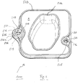
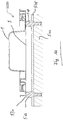
- Fig. 1 shows a blood treatment cassette 1000 according to the invention, also referred to herein as cassette 1000, in a perspective plan view on the main extension plane thereof. Shown is the coupling of the cassette 1000 with the in Fig. 1 Not shown actuator-sensor unit 514 of in Fig. 1 also not shown blood treatment device 5000, herein also referred to as machine 5000, serving side, which is referred to here as the back or docking side.
- the blood treatment cassette 1000 has a hard part 1, which is optionally manufactured by thermoplastic injection molding. Its modulus of elasticity is preferably between 600 and 2800 N / mm 2 . In use, the hard part 1 is preferably at least partially by means of a in Fig. 1 not shown foil 3 covered.
- the cassette 1000 in addition to elements that are relevant for the blood treatment, such as chamber boundaries 502, at least one - preferably peripheral - edge web 503 on.
- the latter serves in addition to the sealing of portions of the cassette 1000 with respect to in Fig. 1 not shown machine 5000 and the orientation of the cassette 1000 on the machine 5000 with the aim to contribute to a flat system of the cassette 1000 on the machine 5000, also as Abhebelsteg in the disassembly of the cassette 1000th
- the cassette 1000 further includes a first centering device 504 which, in addition to centering the cassette 1000 relative to the machine 5000, may also serve to temporarily secure the cassette 1000 to the machine 5000.
- the first centering device 504 may be referred to as the translationally play-free origin of the orientation of the cassette 1000. It may, as well as the second centering device 505 described below, be configured as Zentrierrasthülse.
- the first centering device 504 is preferably arranged on the edge or on one side of the cassette 1000. It is preferably in the middle of a page or long side, so centrally located. Preferably, it is arranged at an identical or comparable distance in each case to alignment-critical structures of the cassette 1000 (for example sensor and valve points) which are relevant for the blood treatment.
- a second centering device 505 is designed as a rotary backlash-aligning Zentrierrasthggse on the cassette 1000th intended. It preferably lies on one side or longitudinal side of the cassette 1000, which lies opposite that side on which the first centering device 504 lies. In this way, an advantageously large distance between the first centering device 504 and the second centering device 505 is achieved.
- the first centering device 504 has a take-off edge web 506. It also has at least one insertion bevel facing towards the actuator-sensor unit (ie, the insertion bevel opens towards the actuator-sensor unit, for example opens like a funnel) or such an insertion funnel 507. With the insertion funnel 507, the rounded edge of the first or second centering device 504, 505 is thus designated in this exemplary embodiment. It serves for coarse pre-centering of the cassette 1000.
- the Abhebel-edge web 506 is a stiffened support surface (no support line and no support point but-surface), which initiates the resulting forces in the machine-side actuator sensor mat 515 when tilting the cartridge when levering and disengaging to the actuator sensor mat 515 to protect against excessive wear.
- the Abhebel-edge web 506 may be spaced in the main plane of extension of the edge of the centering and / or increased, so that due to the bending moment during tilting and levering and disengagement of the cartridge required for disengagement, axial force component occurs.
- the Abhebel-edge web 506 can, as in Fig. 1 1, a bevel facet 506a may be provided which may be on a side surface of the peel edge ridge 506.
- the Abhebel-edge web 506 may further, as in Fig. 1b 1, a rounded edge 506b is located between the bevel facet 506a and a generally horizontal end face 506c of the peel edge ridge 506.
- the Abhebel edge web 506 is also from the enlarged views in Fig. 1a and 1b forth, where Fig. 1a an enlargement of the first centering device 504 in the view of Fig. 1 shows, and where Fig. 1b an enlargement of the Abhebel edge web 506 of Fig. 1 or the Fig. 1a shows.
- Fig. 1c an enlargement of a section Fig. 1 , which for the representation Fig. 1c is cut, facing from the opposite direction.
- Fig. 1c shows only three of the four total distributed over the circumference of the insertion funnel 507 Zentrierfacetten 509 of the first centering device 504 due to the cut.
- the centering facets 509 are at least partially or in their upper part part of the insertion funnel 507. They are arranged above the locking edge 512.
- the first centering device 504 has four centering facets 509 which second centering device 505, however, only two, as well as in Fig. 1 can be seen.
- the centering facets 509 may extend in a plane perpendicular to the main extension plane of the cassette 1000 (at least locally or in sections).
- the centering facets 509 are used for local or point contact with the respective Zentrierrastpin 517, 518. They centering the Zentrierrastpins 517, 518 thus translational or centering each with respect to a translational displacement.
- the centering facets 509 may, for example, directly adjoin or be part of the respective insertion funnel 507, as stated above. They extend, for example, only between approximately 5 and 30% of the centering diameter 522 in the axial direction along the axis of rotation of the Zentrierrastpins 517, 518 or the Zentrierrasthülsen or perpendicular to the film plane or the main extension plane before the end of the axial overlap with the centering (characterized by Centering diameter and centering height) of Zentrierrastpins 517, 518) is reached.
- the centering facets 509 extend, for example, by about 10 to 80% of the centering diameter 522.
- one or all of the centering facets 509 may be wider at the top than at the bottom.
- Centering facets 509 or their extension axes can be arranged in planes perpendicular or substantially perpendicular to the film plane or substantially parallel to the centering pin symmetry axis.
- the facet surfaces thus result in small areas, each of which can be arranged substantially perpendicular to the film plane.
- the line contact may be a line, for example, a value in the range of 0 to 30% of the centering diameter 522.
- This short contact line preferably extends substantially parallel to the axis of symmetry of the centering pin 517, 518.
- the first centering device 504 preferably has four first facet surfaces 509 (but it could also be three, five, six or more facet surfaces).
- the second centering device 505 has in the present example two (exactly two, because of the deliberately deliberately omitted translational attachment along the connection axis between the two centering devices 504, 505).
- the exactly two facet surfaces 509 face each other in parallel and in mirror image with respect to a plane which is arranged substantially perpendicular to the film plane and thereby contains the connecting line between the two centering devices 504 and 505 and both axes of symmetry of the two centering pegs 517, 518 ,
- two facet surfaces each lie parallel and mirror-image with respect to a plane which is arranged substantially at right angles to the film plane (ie contains the axis of symmetry of the first centering device 504).
- the square is here additionally aligned again at the connecting line between the two centering devices.
- the orientation may be such that the connecting line intersects square sides at right angles.
- the square shape and this alignment need not be in order to fulfill the proper function as translational play-free alignment zero point. Rather, the centering hole shape of a triangle, pentagon or hexagon with any rotational alignment is possible and encompassed by the present invention.
- the centering facets 509 may be part of the insertion funnel 507. They are, at least in sections, advantageously in an upper region of the insertion funnel 507, see also the enlarged view in Fig. 1c ,
- Fig. 1c is the side of the cassette 1000, which in use to the actuator-sensor mat 516 shows the top.
- the side of the cassette 1000 or the side of the cassette 1000, which is in use to the machine door, is at the bottom.
- the centering facets are 509 in certain exemplary embodiments above the locking edge (s) 512. Above this is to be understood as closer to the actuator sensor mat 516 out, below as further to the front of the cassette out or to understand the machine door.
- the latching edges 512 are configured in preferred, exemplary embodiments according to the invention as straight or curved edges. This embodiment allows approximately a point contact with a locking diameter 521 of a Fig. 1 Not shown Zentrierrastpins 517, 518, in contrast to an elongated or (large) surface contact.
- first centering device 504 and / or the second centering device 505 in certain exemplary embodiments of the invention not only center but also contribute to or contribute to the latching of the cassette 1000 to the machine 5000, in such embodiments they may also be referred to as centering detents.
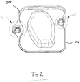
- Fig. 2 shows the cassette 1000 of Fig. 1 in a perspective plan view of the door side.
- the door side can be optionally pressed by means of an in Fig. 2 not shown machine door 524 serve. It lies opposite the coupling side and can be called the front side.
- Fig. 2 shows another - here again only optionally circumferentially shown - edge bar 508.
- This can be described as multifunctional, since it not only serves as a surface (preferably in a plane) for the transmission of the compression effect by means of the machine door 524, but also for stiffening the cassette 1000 and for stiffening connection of the first centering device 504 and / or the second centering device 505. It can also the transmission of the up and Abrüst member and ways of those (Any) places at which the user touches the cassette 1000 for disarming and from which starting forces are transmitted via the first centering device 504 and / or the second centering device 505 in the cassette 1000 and on the Zentrierrastpins 517, 518 serve.
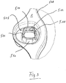
- Fig. 3 shows the detail view G of Fig. 2 .
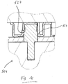
- Fig. 4 shows the detail view F of Fig. 2 .
- the reference numeral 510 designates latching tongues in the figures, which are parts of the first centering device 504 and / or the second centering device 505.
- Per centering device 504, 505 preferably at least two locking tongues 510 are provided, preferably opposite each other.
- the latching tongues 510 can be designed elastically bendable for the intended use. They can be separated from one another by cuts 511, which contributes to the targeted flexing of the locking tongues 510.
- Each latching tongue 510 has at least or exactly one latching edge 512. This extends in a first plane parallel to the main extension plane preferably locally straight in a plane parallel to the main extension plane of the cassette 1000 to allow a displacement relative to the Zentrierrastpins 517, 518 without changing the detent-holding force, and also a priority of the centering of the Zentrierfacetten 509 guarantee.
- the locking edge 512 is in preferred embodiments according to the invention in a second plane which is perpendicular to Main extension plane is, a curved edge or has such. This shape allows a line contact with the likewise curved grooves of the Zentrierrastpins 517, 518 and thus causes minimization of friction during up and Abrüst operations.
- Fig. 5 shows the actuator-sensor unit 514 of the machine 5000 in a perspective plan view of the main extension plane of the former.
- Fig. 6 is the detail view H off Fig. 5 in perspective.
- Fig. 7 is the detail view H off Fig. 5 on average.
- Reference numeral 514 in the figures refers to the actuator-sensor unit 514 of the machine 5000, where 515 denotes the actuator-sensor mat of the unit 514.
- the actuator-sensor mat 515 is only provided as an option and likewise designed to be flat on the cassette 1000, for preferably even coupling.
- 516 denotes the actuator-sensor plate, it is rigid reference body and anchoring ground for the first and the second Zentrierrastpin 517 and 518, respectively.
- the first Zentrierrastpin 517 is provided for locking with the first centering device 504, while the second Zentrierrastpin 518 is provided for locking with the second centering device 505.
- the limitation of the tilting advantageously results from the fact that the tilting angle steadily increases during the tilting expansion movement; because of the same time As a result, the centering device is displaced relative to the centering pin in parallel with the increase in the tilting angle. Since the centering height 523 of Zentrierrastpins 517, 518 is limited, the corresponding centering 504, 505 comes in a non-critical with respect to the canting angle with low tilt angle in the centering facets 509 disengaged from the centering 522 Zentrierrastpins 517, 518th
- Fig. 8 shows in plan view the cassette and sections of the machine in the upgraded state without an already purely optional machine door.
- Fig. 9 shows a section along the line HH of Fig. 8 ; is added to the Fig. 8 the optional machine door 524; shown is the compressed state.
- the optional machine door 524 is for pressing the cassette 1000 and aligning it in a plane should the cassette 1000 be wound once or bent.
- the alignment takes place on the actuator-sensor unit 514 and by means of the peripheral edge web 508 and possibly further, optional, flat support zones 525 and 526.
- the cassette 1000 abuts against the actuator-sensor mat 515 during the blood treatment by means of frictional engagement. This ensures that the centering position of the cartridge 1000 is maintained even when mechanical or fluidic forces are applied to the cartridge 1000 or connecting hoses connected thereto.
- all bearing surfaces of the machine door 524 that contact the cartridge 1000 are parallel to the main plane of extension of the cartridge 1000. This advantageously ensures sole centering of the cartridge 1000 via the centering pegs 517 and 518.
- Fig. 10 shows the first centering device 504 in detail along the line SS of Fig. 8 on average.
- Fig. 11 shows the second centering device 505 in detail along the line KK of Fig. 8 on average.
- Fig. 12 and Fig. 13 show detailed views of the first and second centering device 504 and 505 along the line HH of Fig. 8 on average.
- Fig. 10 shows the first centering device 504 in a cutting direction SS Fig. 8 in which the two short opposing contact lines or line contact sections 527 are each of equal length and comparatively long (since the lever edge distance to the cassette edge webs at the top and bottom is very long).
- Fig. 11 shows a cut to the Fig. 10 analogue cut. That too Fig. 10 This can also be said Fig. 11 hold true.
- Fig. 12 shows the section through the first centering device along the section HH, which is particularly unfavorably affected by the initiation of larger tilts when up and disassembling, as in the Fig. 20 to 23 shown.
- Fig. 12 If one sees a left, shorter line contact section 527 on the left, which is characterized by the inverting anticipated pre-tilted arrangement of Zentrierengstelle Fig. 26 is also located farther away from the actuator sensor mat 515 than the right longer line contact portion 527 on the right.
- the line contact portions 527 or line pieces preferably dot-dot the centering pins 517, 518 at the centering diameter 522, see also Fig. 24 ,
- the tolerance situation of the passage width between the line contact sections 527 and the centering diameters 522 of Zentrierrastpins 517, 518 is preferably selected so that always backlash (ie no game) is given, from the play-free system to complete Zentrierverrastung the cassette 1000. Due to the punctiform or short-line installation of all (here: four) centering facets 509 of the first centering device and the (here: two) centering facets 509 of the second centering device.
- Zentrierrastpin 517, 518 pressed with the comparatively softer Zentrierfacetten 509 wherein the diameter of the Zentrierrastpins 517, 518 measured at the distance between opposite Zentrierfacetten preferably has an excess, deforms the softer surface at least partially elastic and partially plastic.
- a point contact becomes a circular or oval contact surface and from a line contact a contact surface. The freedom from play in the locked state remains on the one hand always guaranteed.
- the compression forces and thus the frictional forces during disassembly are sufficiently low due to the low modulus of elasticity of the thermoplastic (for example, 1800 N / mm 2) and due to the partial plastic deformation, so that the material does not break when tilted.
- the longitudinal axis of the second centering device 505 is aligned in the direction of the center of the passage bore or opening for the first centering device 504 in order to limit the rotation possibility of the cassette 1000 maximum. At the same time, the longitudinal axis approximately in the direction of the shortest distance to the edge web 508 of the cassette 1000th
- the cuts or slots 511 between the locking tongues 510 are preferably also arranged symmetrically to the connecting axis or line between the first and the second centering device 504, 505 and serve to increase the tilting freedom of movement.
- Fig. 14 shows a first step of the Aufrüstvorgangs, attaching the cartridge 1000.
- the reference numeral 3 denotes the film.
- Fig. 15 shows the second step of the upgrade, the beginning of threading.
- Fig. 16 shows the third step of the upgrade process, the one-sided completion of threading.
- Fig. 17 shows the fourth step of the upgrade process, the two-sided completion of Einfädelept.
- Fig. 18 shows the fifth step of the upgrade process, the one-sided completion of a Zentrierverrastung.
- Fig. 19 shows the sixth step of the upgrade process, the two-sided completion of Zentierverrastept.
- the flat end faces of the centering pins 517, 518 in conjunction with the flat and correspondingly generously dimensioned flat end faces of the cassette 1000 around both centering devices 504, 505 allow an ergonomically acceptable lateral offset 530 of FIG preferably 0.5 to 2.5 times the centering diameter 522 during manual application of the cassette 1000 without risk of damage.
- Zentrierrastpin-Stirn' Due to the selected distance between the centering devices 517, 518 in conjunction with the height difference between the total height of a Zentrierrastpins 517, 518 and the centering 523 is a maximum angular misalignment 532 between the main plane of extension of the cassette 1000 and the main plane of extension of the machine 5000 about 1 ° - 3 ° , In connection with the geometrical designs 'rounded Zentrierrastpin-Stirn', locking diameter 'smaller than centering diameter' and 'insertion bevels of the centering' tilting and thus movement impediments or material overloads are prevented at any running threading.
- both centering devices 504, 505 are inserted into the centering pegs 517, 518 so far that a distance 533 of the two main extension planes (of cassette 1000 on the one hand and actuator-sensor-mat 515 on the other hand) only amounts to approximately 0.02 to 0 , 04 times the centering distance.
- a distance 533 of the two main extension planes (of cassette 1000 on the one hand and actuator-sensor-mat 515 on the other hand) only amounts to approximately 0.02 to 0 , 04 times the centering distance.
- an angular misalignment 534 of more than about 1.5 degrees can not be achieved.
- This slight angular misalignment 534 in conjunction with the choice of material and geometry, does not yet cause jamming forces which lead to overloading of the material of the cassette 1000.
- these canting forces do not exceed the maximum desired latching force of approximately 50 N in all tolerance positions of the dimensions.
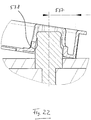
- Fig. 20 shows a critical moment of disengagement on the second centering device 505 during the Abrüstvorgangs.
- Fig. 21 shows a critical moment of disengagement on the first centering device 504 during the Abrüstvorgangs.
- Fig. 22 shows in detail the section O of Fig. 20 .
- Fig. 23 shows in detail the section P of Fig. 21 .
- At the first centering device 504 prevents the tilted assembly 541 of Zentrier devisgangsbohrung in connection with the cuts 511 between the locking tongues 510 and in conjunction with the Aushebel-edge distance 537 and the height and diameter ratios reaching the tilting situation 539.
- An optionally existing, smooth-shaped tongue 540 can not cause critical canting, since it is bendable like the locking tongues 510.
- Fig. 24 shows in a schematic representation of the centering devices 504, 505 with purely exemplary dimensioning and Zentrierrastpins recorded therein.
- Fig. 25 shows in a schematic representation of the tilting with omitted locking tongues 510th
- Fig. 26 shows in a schematic representation of the first centering device 504 in the upgraded position.
- Fig. 27 shows in a schematic representation of the second centering device 505 at the critical moment of Ausrastens.
- the angle of attack 541 of the passage bore or opening of the first centering device 504 is advantageously about 9 ° to 14 °.
- the moment of disengaging the latching tongues 510 substantially coincides with the disengaging 539 of the centering facets 509 with the centering diameter 522 of the Zentrierrastpins 517, 518, wherein projected onto the machine plane distance of the two facets involved during the Aushebel-Abrüst Movement continuously enlarged and always larger than the centering diameter 522 remains.
Description
Die vorliegende Erfindung betrifft eine Flüssigkeitskassette gemäß dem Oberbegriff des Anspruchs 1 und eine Blutbehandlungsvorrichtung gemäß dem Oberbegriff des Anspruchs 10.The present invention relates to a fluid cartridge according to the preamble of
Einmalteilsysteme werden in der Medizin- oder Labortechnik zunehmend als kompakte medizinische Funktionsvorrichtungen wie Kassettensysteme oder Blutbehandlungskassetten ausgeführt, in denen Flüssigkeiten und Gase, insbesondere medizinische Flüssigkeiten und Blut, in Kanälen und Kammern geführt werden. Sind sie zum einmaligen Gebrauch vorgesehen, so spricht man von Kassettendisposables oder Einwegkassetten.Disposable parts systems are increasingly being used in medical or laboratory technology as compact medical functional devices, such as cassette systems or blood treatment cassettes, in which liquids and gases, in particular medical fluids and blood, are guided in channels and chambers. If they are intended for single use, it is called cassette disposables or disposable cassettes.
Zumeist handelt es sich hierbei um Hartteil-Folie-Kassetten. Das Hartteil besteht regelmäßig aus einem Spritzgußwerkstoff wie beispielweise PE, PP, PA, ABS, PMMA, PC oder PVC. In ihm sind beispielsweise Schlauchanschlüsse, Konnektoren, Kammern, Kanäle und Zentriereinrichtungen ausgestaltet. Zu ihrer Verwendung wird die Blutbehandlungskassette beim Einsetzen in die Blutbehandlungsvorrichtung zwischen eine Tür und eine Aktor-Sensor-Einheit der Blutbehandlungsvorrichtung eingesetzt und anschließend die Tür durch ihr Schließen in eine sog. Verpress-Stellung gebracht, bei der die Folie gegen das Hartteil gepresst und die Blutbehandlungskassette mit der Folie räumlich definiert an die Aktor-Sensor-Matte der Aktor-Sensor-Einheit angekoppelt wird. Beim Einsetzen der Blutbehandlungskassette - auch als deren Aufrüsten bezeichnet - wird die Haupterstreckungsebene der Blutbehandlungskassette gegen die Haupterstreckungsebene der Blutbehandlungsvorrichtung (meist die Aktor-Sensor-Matte) ausgerichtet und verpresst. In die Aktor-Sensor-Matte und Aktor-Sensor-Platte (oder -einheit) integrierte Aktoren (hierin auch als Aktuatoren bezeichnet; Komponenten, die der Aktor-Sensor-Platte oder -Matte zuzuordnen sind, werden hierin auch als als "aktor-sensor-seitig" bezeichnet) können Bewegungen durch die Folie hindurch ausüben, wodurch beispielsweise Pump- oder Ventil-Funktionen realisierbar sind. Mittels wenigstens eines, optional in der Aktor-Sensor-Platte vorgesehenen, Sensors können beispielsweise Eigenschaften von Fluiden, welche die Blutbehandlungskassette durchströmen, gemessen werden.
Aus der
From the
Vorrichtungen zum Verbinden einer externen Funktionseinrichtung mit einer Anordnung und Verfahren zum Verbinden sind aus der
Eine Abdichtungseinrichtung zum Abdichten eines Volumens einer medizinischen Behandlungsanordnung gegen ein weiteres Volumen sowie Anordnung und Verfahren sind aus der
Ankoppeleinrichtung, Konnektor, medizinische Funktionseinrichtung und Behandlungsvorrichtung sind in der
In der
Verfahren zur bildgesteuerten Überwachung der Abgabe von Flüssigkeiten in den menschlichen Körper sind aus der
Eine erfindungsgemäße Aufgabe kann darin bestehen, eine weitere medizinische Flüssigkeitskassette (Kassette zur Aufnahme medizinischer Flüssigkeiten), insbesondere eine Blutbehandlungskassette, mit einer Vorrichtung zum Zentrieren der medizinischen Flüssigkeitskassette (im Folgenden kurz: Flüssigkeitskassette) an der Blutbehandlungsvorrichtung vorzuschlagen. Ferner soll eine Blutbehandlungsvorrichtung zum Verwenden der Flüssigkeitskassette angegeben werden.An object of the invention may be to propose a further medical liquid cassette (cassette for receiving medical fluids), in particular a blood treatment cassette, with a device for centering the medical liquid cassette (in the following: liquid cassette) on the blood treatment device. Furthermore, a blood treatment device for using the liquid cassette is to be specified.
Die Aufgabe kann gelöst werden durch eine Flüssigkeitskassette mit den Merkmalen des Anspruchs 1, ferner durch eine Blutbehandlungsvorrichtung mit den Merkmalen des Anspruchs 10.The object can be achieved by a liquid cassette having the features of
Obwohl im Folgenden vornehmlich von einer Blutkassette die Rede ist, stellt diese nur eine mögliche erfindungsgemäße Ausgestaltung der vorliegenden Erfindung dar. Wann immer hierin von der Blutkassette die Rede ist, stellt dies keine Beschränkung dar sondern gilt unverändert auch für eine (ebenfalls erfindungsgemäße Flüssigkeitskassette), selbst wenn diese nicht zur Behandlung von Blut verwendet wird.Although the following is primarily a blood cassette, this represents only one possible embodiment of the present invention. Whenever the blood cassette is mentioned here, this is not a limitation but also applies unchanged to a (likewise inventive fluid cassette), even if it is not used to treat blood.
Erfindungsgemäß wird somit eine Flüssigkeitskassette, insbesondere Blutbehandlungskassette, vorgeschlagen, mit einem als Hartteil ausgestalteten Kassettenkörper. Die Blutbehandlungskassette kann optional eine Folie aufweisen. Ist eine Folie vorgesehen, so ist sie mit dem Hartteil verbunden, deckt das Hartteil zumindest abschnittsweise ab. Das Hartteil weist wenigstens eine erste Zentriervorrichtung und eine zweite Zentriervorrichtung auf. Sie sind bevorzugt an gegenüberliegenden ersten und zweiten Seiten der Blutbehandlungskassette angeordnet oder diesen Seiten zugeordnet.Thus, according to the invention, a liquid cassette, in particular blood treatment cassette, is proposed, with a cassette body designed as a hard part. The blood treatment cassette may optionally comprise a foil. If a film is provided, then it is connected to the hard part, covers the hard part at least in sections. The hard part has at least a first centering device and a second centering device. They are preferred disposed opposite or associated with the first and second sides of the blood treatment cassette.
Ferner wird eine Blutbehandlungsvorrichtung vorgeschlagen, konfiguriert zur Verbindung mit einer erfindungsgemäßen Blutbehandlungskassette, welche eine Aktor-Sensor-Platte mit wenigstens einem Aktuator aufweist. Letzterer ist für eine Interaktion zwischen Aktoren und/oder Sensoren der Blutbehandlungsvorrichtung mit Vorrichtungen der Blutbehandlungskassette konfiguriert.Furthermore, a blood treatment device is proposed, configured for connection to a blood treatment cassette according to the invention, which has an actuator-sensor plate with at least one actuator. The latter is configured for interaction between actuators and / or sensors of the blood treatment device with devices of the blood treatment cassette.
Bei allen folgenden Ausführungen ist der Gebrauch des Ausdrucks "kann sein" bzw. "kann haben" usw. synonym zu "ist vorzugsweise" bzw. "hat vorzugsweise" usw. zu verstehen und soll eine erfindungsgemäße Ausführungsform erläutern.
Wann immer hierin Zahlenworte genannt werden, so versteht der Fachmann diese als Angabe einer zahlenmäßig unteren Grenze. Sofern dies zu keinem für den Fachmann erkennbaren Widerspruch führt, liest der Fachmann daher beispielsweise bei der Angabe "ein" oder "einem" stets "wenigstens ein" oder "wenigstens einem" mit. Dieses Verständnis ist ebenso von der vorliegenden Erfindung mit umfasst wie die Auslegung, dass ein Zahlenwort wie beispielsweise "ein" alternativ als "genau ein" gemeint sein kann, wo immer dies für den Fachmann erkennbar technisch möglich ist. Beides ist von der vorliegenden Erfindung umfasst und gilt für alle hierin verwendeten Zahlenworte.In all of the following, the use of the term "may be" or "may have", etc. is synonymous with "preferably" or "preferably has", etc., and is intended to explain an embodiment of the invention.
Whenever numerical words are mentioned herein, those skilled in the art will understand these as indicating a numerically lower limit. If this does not result in a contradiction that is recognizable to the person skilled in the art, the person skilled in the art therefore always reads "at least one" or "at least one", for example, when specifying "a" or "one". This understanding is also encompassed by the present invention as the interpretation that a numerical word such as "a" may alternatively be meant as "exactly one" wherever technically possible for those skilled in the art. Both are encompassed by the present invention and apply to all number words used herein.
Hierin gemachte räumliche Angaben wie "oben", "unten", usw. beziehen sich im Zweifel auf die Darstellung, wie sie den hier beigefügten Figuren zu entnehmen ist.Spatial statements made herein, such as "top", "bottom", etc., refer in case of doubt to the illustration as it appears from the attached figures.
Vorteilhafte Weiterentwicklungen der vorliegenden Erfindung sind jeweils Gegenstand von Unteransprüchen und Ausführungsformen.Advantageous developments of the present invention are the subject of subclaims and embodiments.
Erfindungsgemäße Ausführungsformen können eines oder mehrere der oben und/oder im Folgenden genannten Merkmale in beliebiger Kombination aufweisen.Embodiments of the invention may include one or more of the features listed above and / or below in any combination.
In bestimmten beispielhaften erfindungsgemäßen Ausführungsformen weist die Blutbehandlungskassette an einer Vorder- und/oder Rückseite hiervon wenigstens einen, vorzugsweise umlaufenden, Randsteg mit einer Stirnfläche auf. Die Stirnfläche liegt in einer Ebene, welche vorzugsweise parallel zu einer Haupterstreckungsebene der Blutbehandlungskassette liegt.In certain exemplary embodiments of the invention, the blood treatment cassette has at least one, preferably circumferential, edge web with an end face on a front and / or rear side thereof. The end face lies in a plane which is preferably parallel to a main extension plane of the blood treatment cassette.
Die Stirnfläche ist in einigen beispielhaften erfindungsgemäßen Ausführungsformen vorzugsweise eben. Sie liegt in diesen Ausführungsformen also ausschließlich in einer Ebene.The end face is preferably planar in some exemplary embodiments of the invention. In these embodiments, therefore, it lies exclusively in one plane.
Die Haupterstreckungsebene ist in einigen beispielhaften erfindungsgemäßen Ausführungsformen parallel zu einer von der, falls vorhanden, Folie aufgespannten Ebene oder Haupterstreckungsebene.The principal plane of extension, in some exemplary embodiments of the invention, is parallel to a plane spanned by the foil, if present, or main plane of extension.
In manchen beispielhaften erfindungsgemäßen Ausführungsformen ist die Blutbehandlungskassette ausgestaltet, um im bestimmungsgemäßen Gebrauch der Blutbehandlungskassette in der Haupterstreckungsebene translatorisch spielfrei mit einem ersten Zentrierrastpin einer Blutbehandlungsvorrichtung verbunden zu sein. Die zweite Zentriervorrichtung ist in diesem Ausführungsformen ausgestaltet, um im bestimmungsgemäßen Gebrauch der Blutbehandlungskassette um eine Achse, die vorzugsweise senkrecht oder im Wesentlichen senkrecht zur Haupterstreckungsebene ist, rotatorisch spielfrei mit einem zweiten Zentrierrastpin der Blutbehandlungsvorrichtung verbunden zu sein.In some exemplary embodiments according to the invention, the blood treatment cassette is designed to be connected in the intended use of the blood treatment cassette in the main extension plane in a translationally play-free manner with a first centering pin of a blood treatment device. The second centering device is designed in this embodiment, in order to Proper use of the blood treatment cassette about an axis, which is preferably perpendicular or substantially perpendicular to the main extension plane, rotationally free of play connected to a second Zentrierrastpin the blood treatment device.
In bestimmten beispielhaften erfindungsgemäßen Ausführungsformen weist die erste Zentriervorrichtung Zentrierfacetten auf, deren Zentrierflächen sich zumindest abschnittsweise jeweils in einer Ebene vorzugsweise senkrecht oder im Wesentlichen senkrecht zur Haupterstreckungsebene der Blutbehandlungskassette erstrecken. In einigen erfindungsgemäßen Ausführungsformen berühren die Zentrierfacetten den ersten Zentrierrastpin zumindest abschnittsweise und vorzugsweise tangentiell.In certain exemplary embodiments according to the invention, the first centering device has centering facets whose centering surfaces extend, at least in sections, in each case in a plane preferably perpendicular or substantially perpendicular to the main extension plane of the blood treatment cassette. In some embodiments according to the invention, the centering facets touch the first centering pin at least in sections, and preferably tangentially.
In manchen beispielhaften erfindungsgemäßen Ausführungsformen weisen die Zentrierfacetten - ganz oder zumindest abschnittsweise - sich in ein Inneres einer Durchlassbohrung oder -öffnung der ersten Zentriervorrichtung hinein wölbende Kanten auf oder sind als solche ausgestaltet.In some exemplary embodiments according to the invention, the centering facets-entirely or at least in sections-have bulging edges in an interior of a passage bore or opening of the first centering device or are designed as such.
In bestimmten beispielhaften erfindungsgemäßen Ausführungsformen ist eine Zentrierfacette zumindest teilweise ein Abschnitt eines Einführabschnitts, einer Einführschräge oder eines Einführtrichters einer Zentriervorrichtung, wobei der Einführabschnitt, die Einführschräge oder der Einführtrichter zur Aufnahme eines Abschnitts des Zentrierrastpins dient. Dieser Abschnitt, also die Zentrierfacette selbst, hat - beispielsweise oder vorzugsweise in wenigstens einer Raumrichtung oder in zwei aufeinander senkrecht stehenden Raumrichtungen - eine andere Krümmung und/oder Neigung als andere Abschnitte des Einführabschnitts, der Einführschräge oder des Einführtrichters oder als benachbarte, beispielsweise auf derselben Höhe (etwa bezogen auf eine Einführrichtung oder -tiefe) liegende, Abschnitte des Einführabschnitts, der Einführschräge oder des Einführtrichters.In certain exemplary embodiments of the invention, a centering facet is at least partially a portion of an insertion portion, an insertion slope, or an insertion funnel of a centering device, wherein the insertion portion, the insertion slope, or the insertion funnel is for receiving a portion of the centering peg. This section, ie the centering facet itself, has-for example or preferably in at least one spatial direction or in two mutually perpendicular spatial directions-a different curvature and / or inclination than other sections of the insertion section, the insertion bevel or the insertion funnel or as adjacent, for example at the same height (approximately with respect to an insertion direction or depth) lying, portions of the insertion, the insertion or the insertion funnel.
In einigen beispielhaften erfindungsgemäßen Ausführungsformen ist eine Zentrierfacette ein Abschnitt des Einführtrichters oder des Einführabschnitts, in welchem der Abschnitt oder der Trichter einen größeren Innendurchmesser oder eine größere lichte Weite hat als an anderen und/oder an zur Zentrierfacette benachbarten Abschnitten des Abschnitts oder Trichters.In some example embodiments of the invention, a centering facet is a portion of the insertion funnel or insert portion in which the portion or funnel has a larger inner diameter or greater clearance than at other portions of the portion or funnel adjacent to the centering facet.
Der Einführtrichter oder Einführabschnitt weist in manchen beispielhaften erfindungsgemäßen Ausführungsformen, beispielsweise in einer Schnittdarstellung hiervon, zumindest abschnittsweise eine mehr oder weniger ausgeprägte Trichterform auf. Dabei öffnet sich der Einführtrichter zu einem Äußeren der Zentriervorrichtung hin und/oder wird in Einführrichtung des Zentrierrastpins enger.In some exemplary embodiments according to the invention, for example in a sectional representation thereof, the insertion funnel or insertion section has, at least in sections, a more or less pronounced funnel shape. In this case, the insertion funnel opens towards an exterior of the centering device and / or becomes narrower in the insertion direction of the centering locking pin.
Der Einführtrichter, der Einführabschnitt oder die Einführschräge können einen nach innen und/oder nach außen (bezogen auf den Durchmesser des Einführtrichters oder des Einführabschnitts, jeweils im Bereich des Einlasses) abgerundeten Einlass oder Rand haben. Die Abrundung kann umlaufend sein oder nur in Abschnitten des Rands vorliegen.The insertion funnel, the insertion section or the insertion bevel may have an inlet or edge rounded inwards and / or outwards (relative to the diameter of the insertion funnel or of the insertion section, in each case in the region of the inlet). The rounding may be circumferential or present only in portions of the edge.
Eine Rastkante ist in manchen beispielhaften erfindungsgemäßen Ausführungsformen als eine Kontaktfläche ähnlich einer Beißfläche einer Beißzange ausgestaltet.A locking edge is configured in some exemplary embodiments of the invention as a contact surface similar to a biting surface of a pair of pliers.
In bestimmten beispielhaften erfindungsgemäßen Ausführungsformen weist die erste Zentriervorrichtung wenigstens einen Abhebel-Randsteg auf. Dieser kann am - bezogen auf die Mitte der Blutbehandlungskassette - äußersten Rand der ersten Zentriervorrichtung liegen oder diese nach lateral begrenzen.In certain exemplary embodiments according to the invention, the first centering device has at least one lever edge web. This may be located at the outermost edge of the first centering device or laterally bounded with respect to the center of the blood treatment cassette.
Erfindungsgemäß weisen die erste Zentriervorrichtung und/oder die zweite Zentriervorrichtung jeweils wenigstens eine aktor-sensor-seitige Einführschräge oder wenigstens einen Einführtrichter, zum Aufnehmen eines Abschnitts eines Zentrierrastpins, auf.According to the invention, the first centering device and / or the second centering device each have at least one actuator-sensor-side insertion bevel or at least one insertion funnel for receiving a portion of a centering-locking pin.
In bestimmten beispielhaften erfindungsgemäßen Ausführungsformen weisen die erste und/oder die zweite Zentriervorrichtung wenigstens zwei Rastzungen mit wenigstens je einer Rastkante auf. Die Rastkante verläuft dabei - vorzugsweise vollständig, im Wesentlichen oder zumindest abschnittsweise - in einer Ebene parallel zur Haupterstreckungsebene der Blutbehandlungskassette.In certain exemplary embodiments according to the invention, the first and / or the second centering device have at least two latching tongues with at least one latching edge each. The latching edge runs - preferably completely, substantially or at least in sections - in a plane parallel to the main extension plane of the blood treatment cassette.
Erfindungsgemäß weist die Durchlassbohrung oder -öffnung der zweiten Zentriervorrichtung im Wesentlichen oder vollständig die Form eines Rechtecks oder eines Langlochs auf.According to the invention, the passage bore or opening of the second centering device substantially or completely in the form of a rectangle or a slot.
In bestimmten beispielhaften erfindungsgemäßen Ausführungsformen ist die Längsachse der zweiten Zentriervorrichtung in Richtung auf den Mittelpunkt der Durchlassbohrung oder -öffnung der ersten Zentriervorrichtung ausgerichtet.In certain exemplary embodiments of the invention, the longitudinal axis of the second centering device is oriented toward the center of the passage bore or opening of the first centering device.
Erfindungsgemäß ist die Blutbehandlungsvorrichtung mit einer erfindungsgemäßen Blutbehandlungskassette verbunden.According to the invention, the blood treatment device is connected to a blood treatment cassette according to the invention.
Erfindungsgemäß weist ein erster Zentrierrastpin und/oder ein zweiter Zentrierrastpin einen Zentrierdurchmesser auf. Er weist ferner einen Rastdurchmesser auf, welcher geringer ist als der Zentrierdurchmesser.According to the invention, a first centering pin and / or a second centering pin have a centering diameter. He also has a locking diameter, which is less than the centering diameter.
In einigen beispielhaften erfindungsgemäßen Ausführungsformen geht ein zwischen dem Zentrierdurchmesser und dem einen Rastdurchmesser liegender Umfangsabschnitt des Zentrierrastpins mittels gerundeten Übergangs in den Zentrierdurchmesser und/oder in den Rastdurchmesser über.In some exemplary embodiments according to the invention, a circumferential section of the centering locking pin lying between the centering diameter and the one locking diameter merges into the centering diameter and / or the locking diameter by means of a rounded transition.
In bestimmten beispielhaften erfindungsgemäßen Ausführungsformen weist der erste Zentrierrastpin und/oder der zweite Zentrierrastpin eine ebene Stirnfläche auf.In certain exemplary embodiments of the invention, the first Zentrierrastpin and / or the second Zentrierrastpin a flat end face.
In manchen beispielhaften erfindungsgemäßen Ausführungsformen weist der erste Zentrierrastpin und/oder der zweite Zentrierrastpin eine gerundete Stirnflächenkante auf. Die Stirnkante ist jene Kante, an welcher die Stirnfläche in die Mantelfläche oder die Umfangsfläche des Zentrierrastpins übergeht.In some exemplary embodiments of the invention, the first Zentrierrastpin and / or the second Zentrierrastpin a rounded end face edge. The front edge is that edge at which the end surface merges into the lateral surface or the circumferential surface of the Zentrierrastpins.
In bestimmten beispielhaften erfindungsgemäßen Ausführungsformen haben der erste Zentrierrastpin und/oder der zweite Zentrierrastpin eine Zentrierhöhe, welche im Bereich des 0,1 bis 0,5-fachen ihres Zentrierdurchmessers liegt. Die Zentrierhöhe ist dabei die freie Höhe oder die Höhe, mit der sich der Zentrierrastpin - vorzugsweise mit oder nur mit seinem Zentrierdurchmesser, nicht aber mit seiner gesamten Höhe - über das Niveau der ihn umgebenden Aktor-Sensor-Matte erhebt. Der Zentrierdurchmesser ist jener Durchmesser des Zentrierrastpins, welcher die Zentrierfunktion des Zentrierrastpins übernimmt. Der Zentrierdurchmesser kann der breiteste Durchmesser des über die Aktor-Sensor-Matte überstehenden Abschnitts des Zentrierrastpins sein. Er kann der Durchmesser jenes Abschnitts des Zentrierrastpins sein, welcher sich unmittelbar oberhalb der Aktor-Sensor-Matte an diese anschließt.In certain exemplary embodiments of the invention, the first centering pin and / or the second centering pin have a centering height which is in the range of 0.1 to 0.5 times their centering diameter. The centering height is the free height or height at which the Zentrierrastpin - preferably with or only with its centering diameter, but not with its entire height - rises above the level of the actuator sensor mat surrounding it. The centering diameter is the diameter of the Zentrierrastpins, which the centering function of Centering pins takes over. The centering diameter may be the widest diameter of the portion of the centering pint protruding beyond the actuator sensor mat. It may be the diameter of that portion of the Zentrierrastpins, which adjoins this immediately above the actuator sensor mat.
In manchen beispielhaften erfindungsgemäßen Ausführungsformen dienen die erste Zentriervorrichtung und/oder die zweite Zentriervorrichtung nicht nur dem Zentrieren sondern auch dem Verrasten der Blutbehandlungskassette an der Blutbehandlungsvorrichtung.In some exemplary embodiments of the invention, the first centering device and / or the second centering device serve not only for centering but also for latching the blood treatment cassette to the blood treatment device.
In bestimmten beispielhaften erfindungsgemäßen Ausführungsformen liegt die Maschinentür bevorzugt auf türseitigen (also maschinenseitigen) Stützstegen und auf den ebenen Stirnflächen der Rastzungen auf.In certain exemplary embodiments according to the invention, the machine door preferably rests on door-side (ie machine-side) support webs and on the flat end faces of the latching tongues.
In einigen beispielhaften erfindungsgemäßen Ausführungsformen ist wenigstens ein Zentrierraststift symmetrisch und/oder als Zylinder ausgestaltet. Er weist in diesen Ausführungsformen einen Zentrierzylinder auf.In some exemplary embodiments according to the invention, at least one centering detent pin is configured symmetrically and / or as a cylinder. He has in these embodiments, a centering cylinder.
In manchen beispielhaften erfindungsgemäßen Ausführungsformen liegen im verpressten Zustand alle Auflageflächen der Maschinentür, welche die Blutbehandlungskassette berühren, parallel zur Haupterstreckungsebene der Kassette. Dies stellt vorteilhaft eine alleinige Zentrierung der Kassette über die Zentrierrastpins sicher.In some exemplary embodiments of the invention, in the compressed state, all the bearing surfaces of the machine door which contact the blood treatment cassette are parallel to the main extension plane of the cassette. This advantageously ensures a sole centering of the cassette on the Zentrierrastpins.
In bestimmten beispielhaften erfindungsgemäßen Ausführungsformen sind die Zentrierrastpins ausgestaltet, um in Verbindung mit den flachen und entsprechend großzügig bemessenen Stirnflächen der Blutbehandlungskassette um beide Zentriervorrichtungen herum einen ergonomisch günstigen zulässigen Lateralversatz von vorzugsweise dem 0,5 bis 2,5-fachen des Zentrierdurchmessers zu gewährleisen oder diesen hierauf zu beschränken.In certain exemplary embodiments of the invention, the centering pegs are configured to be in communication with the flat and correspondingly generous dimensioned end faces of the blood treatment cassette around both centering around an ergonomically favorable allowable lateral offset of preferably 0.5 to 2.5 times the centering diameter to be limited or limited thereto.
In einigen beispielhaften erfindungsgemäßen Ausführungsformen liegt der anfänglich zulässige Lateralversatz der Blutbehandlungskassette, bevor entsprechende Einführschägen in Eingriff kommen, vorzugsweise beim 0,1- bis 0,2-fachen des Zentrierdurchmessers.In some exemplary embodiments of the present invention, the initial allowable lateral offset of the blood processing cassette prior to engaging respective introducer shanks is preferably 0.1 to 0.2 times the centering diameter.
In bestimmten beispielhaften erfindungsgemäßen Ausführungsformen ist einer der Zentrierrastpins in eine der Zentriervorrichtungen - nach Abschluss einer einseitigen Einfädelung - soweit eingefädelt, dass eine oder mehrere der Rastkanten der Zentriervorrichtung an den abgerundeten Stirnflächenkanten des Zentrierrastpins anliegen, während der andere Zentrierrastpin seine Einfädelung noch nicht begonnen oder noch nicht abgeschlossen hat.In certain exemplary embodiments according to the invention, one of the centering pins is threaded into one of the centering devices - after completion of one-sided threading - so far that one or more of the locking edges of the centering device rest against the rounded end face edges of the centering pin, while the other centering pin has not yet begun threading it did not complete.
In bestimmten erfindungsgemäßen Ausführungsformen ist die Blutbehandlungskassette ein Disposable oder ein Einmalartikel.In certain embodiments of the invention, the blood treatment cassette is a disposable or disposable article.
In bestimmten erfindungsgemäßen Ausführungsformen sind die Blutbehandlungskassette und/oder die Blutbehandlungsvorrichtung zur Apherese, zur Hämodialyse, zur Hämofiltration, Hämodiafiltration, Hämoultrafiltration und dergleichen konfiguriert.In certain embodiments of the invention, the blood treatment cassette and / or the blood treatment device are configured for apheresis, hemodialysis, hemofiltration, hemodiafiltration, hemo-ultrafiltration, and the like.
Einige oder alle erfindungsgemäßen Ausführungsformen können einen oder mehrere der oben oder im Folgenden genannten Vorteile aufweisen.Some or all embodiments according to the invention may have one or more of the advantages mentioned above or below.
Zu den erzielbaren Vorteilen kann die spielfreie und reproduzierbare Ausrichtung der Blutbehandlungskassette ungeachtet ihrer Herstelltoleranzen und der Toleranzen der Blutbehandlungsvorrichtung zählen.The achievable advantages may include the zero-backlash and reproducible alignment of the blood treatment cassette regardless of its manufacturing tolerances and the tolerances of the blood treatment device.
Von Vorteil kann ferner sein, dass die Blutbehandlungskassette beim Auf- wie beim Abrüsten an beliebigen Stellen gegriffen werden darf und dass trotz der sich dabei unterscheidenden Verkippungs-Konstellationen jede Phase des Auf- und Abrüstens ordnungsgemäß bzw. wie gewünscht abläuft. Ein fehlerhaftes Auf- oder Abrüsten ist damit bei vielen erfindungsgemäßen Ausführungsformen nicht möglich.It may also be advantageous that the blood treatment cassette may be gripped at arbitrary positions during setup and during disassembly, and that despite the different tilting constellations, each phase of the up and disarming process proceeds properly or as desired. A faulty upgrading or disassembly is therefore not possible in many embodiments according to the invention.
Zum Ein- und Ausschnappen ist nur begrenzter Kraftaufwand beim Aufrüsten oder Abrüsten, beispielsweise weniger als 50 N, erforderlich.To snap in and out is only a limited amount of force when upgrading or disarming, for example, less than 50 N, required.
Verkippungsbedingte Materialspannungen der Blutbehandlungskassette können vorteilhaft auf Werte deutlich unterhalb jener Schwelle begrenzt werden, ab welcher es zu Zerstörungen an der Blutbehandlungskassette kommen kann; dies gilt auch für ein ruckartiges Abrüsten.Advantageously, tilting material tensions of the blood treatment cassette can be limited to values well below the threshold above which destruction of the blood treatment cassette can occur; This also applies to a jerky disassembly.
Erfindungsgemäß kann eine ergonomisch einfache manuelle Auf- und Abrüstung der Blutbehandlungskassette auf die Blutbehandlungsvorrichtung gewährleistet werden bei zugleich spielfreier Zentrierung und einer zerstörungssicheren Anordnung. Unzulässig starke Verkantungen und daraus entstehende Materialspannungen können dabei ausgeschlossen werden. Bei den Auf- und Abrüstvorgängen darf die Bedienperson die Blutbehandlungskassette an beliebigen Stellen greifen und belasten. Auch die Reihenfolge der Ein- und Ausrastungen darf beliebig stattfinden.According to the invention, an ergonomically simple manual assembly and disarming of the blood treatment cassette to the blood treatment device can be ensured while at the same time backlash-free centering and a non-destructive arrangement. Impermissibly strong tilting and resulting material stresses can be ruled out. During the setup and disarming operations, the operator may grab the blood treatment cassette anywhere and strain. Also, the order of locking and unlocking may take place arbitrarily.
Die spielfreie und maximal hohe Zentriergenauigkeit wird vorteilhaft erstens durch das Vorsehen zweier voneinander entfernter Zentriervorrichtungen erreicht, wobei die erste Zentriervorrichtung den Nullpunkt der translatorischen Verschiebung definiert und die zweite Zentriervorrichtung, welche bevorzugt langlochartig ausgestaltet ist, die Winkelausrichtung festlegt und dabei die globalen Abmessungstoleranzen zwischen Blutbehandlungsvorrichtung und Blutbehandlungskassette ausgleicht. Zweitens entsteht die Spielfreiheit durch die lokale Anwendung der Facetten-Zentrierung. Lokal bedeutet hier, dass es um die Toleranzzuordnung der Zentrierdurchmesser der Zentrierrastpins zu den facettierten Zentrierbohrungen oder -öffnungen der Zentriervorrichtungen geht (mit deutlich geringeren Toleranzen als beim Abstand zwischen beiden Zentriervorrichtungen).The zero backlash and maximum centering accuracy is advantageously achieved first by the provision of two spaced apart centering, the first centering defines the zero point of translational displacement and the second centering, which is preferably slot-like, determines the angular orientation and thereby the global dimensional tolerances between blood treatment device and Balancing blood treatment cassette. Secondly, the backlash is created by the local application of facet centering. Local here means that it is about the tolerance assignment of the centering diameter of Zentrierrastpins to the faceted centering holes or openings of the centering (with significantly lower tolerances than the distance between the two centering).
Aufgrund der geometrischen Gestaltung mit Punktberührung in Verbindung mit der Nachgiebigkeit des Blutbehandlungskassettenmaterials kann die Spielfreiheit in allen Toleranzlagen erreicht werden ohne Materialzerstörung oder zu große Auf- und Abrüstkräfte hervorzurufen.Due to the geometric design with point contact in conjunction with the compliance of the blood treatment cassette material, the backlash can be achieved in all tolerance positions without causing material destruction or too large up and Abrüstkräfte.
Aufgrund der manuellen Betätigung in Verbindung mit den spielfreien (oder optional spielarmen) Anordnungen der Zentriervorrichtungen auf den Zentrierrastpins ergeben sich im Stand der Technik die Möglichkeit der Verkantung und die damit verbundenen Materialspannungen und Steigerungen der Auf- und Abrüstkräfte auf bruchgefährliche Werte. Um dieses Problem erfindungsgemäß auszuschließen oder zu miminieren, wird von folgenden Prinzipien vorteilhaft Gebrauch gemacht: Beim Aufrüsten gewährleisten die erfindungsgemäß festgelegten (Rand-) Abstands-, Höhen- und Durchmesserverhältnisse vorteilhaft, dass alle möglichen Verkippungen zwischen Blutbehandlungskassette und Blutbehandlungsvorrichtung in Winkelbereichen bleiben, die unterhalb der kritischen Verkantungswinkel liegen.Due to the manual operation in conjunction with the backlash-free (or optionally low-backlash) arrangements of the centering on the Zentrierrastpins arise in the prior art, the possibility of canting and the associated material stresses and increases in the up and Abrüstkräfte to fracture dangerous values. In order to exclude or eliminate this problem according to the invention, use is advantageously made of the following principles: During the upgrade, the (boundary) clearance, height and diameter ratios determined according to the invention advantageously ensure that all possible tiltings between the blood treatment cartridge and the blood treatment device remain in angular ranges that are below the critical tilt angles.
Beim Abrüsten sorgt die gewählte Biegesteifigkeit der Blutbehandlungskassette in Verbindung mit den Abständen der Zentrierraststellen zu den entfernten Randstegen der Blutbehandlungskassette und der Zentrierhöhe der Zentrierrastpins dafür, dass durch den Aushebeleffekt an den Randstegen bei verkippender vorheriger einseitiger Ausrastung der verkantungskritische Winkelbereich nicht erreicht werden kann, sondern unmittelbar zuvor die Ausrastung auch der verbleibenden Zentriervorrichtung erfolgt.When disarming the selected bending stiffness of the blood treatment cassette in conjunction with the distances of the Zentrierraststellen to the distal edge webs of the blood treatment cassette and the centering of the Zentrierrastpins ensures that can not be achieved by the Aushebeleffekt on the edge webs with tilting previous one-sided disengagement of the critical angular angular range, but immediately previously the disengagement of the remaining centering device takes place.
Beim Abrüsten sorgt die gewählte Biegesteifigkeit der Blutbehandlungskassette in Verbindung mit dem geringeren Abstand des Randsteges zur ersten Zentriervorrichtung, der gewählten Zentrierhöhe und der verkippten Anordnung der Zentrierfacetten der zweiten Zentriervorrichtung dafür, dass in Verbindung mit dem verringerten Aushebeleffekt bei verkippender einseitiger Ausrastung in der maximal ungünstigsten, möglichen Verkipprichtung der verkantungskritische Winkelbereich vorteilhaft nicht erreicht werden kann.When disarming the selected flexural rigidity of the blood treatment cassette in conjunction with the smaller distance of the edge web to the first centering, the selected centering and the tilted arrangement of Zentrierfacetten the second centering ensures that in conjunction with the reduced Aushebeleffekt at tilting unilateral disengagement in the most unfavorable possible Verkipprichtung the tilt critical angular range can not be achieved advantageous.
Beim Abrüsten sorgt die gewählte Biegesteifigkeit der Blutbehandlungskassette in Verbindung mit dem geringeren Abstand des Randsteges zur zweiten Zentriervorrichtung, der gewählten Zentrierhöhe und der langlochförmigen Gestaltung der Zentrierdurchgangsbohrung oder -öffnung der zweiten Zentriervorrichtung dafür, dass in Verbindung mit dem reduzierten Aushebeleffekt bei verkippender einseitiger Ausrastung in der maximal ungünstigsten, möglichen Verkipprichtung der verkantungskritische Winkelbereich vorteilhaft nicht erreicht werden kann.When disarming the selected bending stiffness of the blood treatment cassette in conjunction with the smaller distance of the edge web to the second centering device, the selected centering and the slot-like design of the Centering through hole or opening of the second centering device that in connection with the reduced Aushebeleffekt in tilting one-sided disengagement in the maximum unfavorable possible Verkipprichtung the cant critical angular range can not be achieved advantageous.
Beim Auf- und Abrüsten mit beliebigen möglichen Verkippungen erlaubt der Rastdurchmesser der Zentrierrastpins, welcher kleiner als der Zentrierdurchmesser bestimmt wurde, in Verbindung mit seiner gering gewählten Gesamthöhe im Vergleich zur Zentrierhöhe und zum Abstand zwischen den Zentrierraststellen vorteilhaft einen ausreichend großen verkantungsunkritischen Verkippwinkelbereich.When mounting and dismantling with any possible tilting allows the locking diameter of the Zentrierrastpins, which was determined to be smaller than the centering diameter, in conjunction with its low overall height compared to the centering and the distance between the Zentrierraststellen advantageously a large Verkantungsuncritical Verkippungswinkelbereich.
Beim Auf- und Abrüsten mit beliebigen möglichen Verkippungen auch in andere nicht dargestellte Raumrichtungen erlauben die biegbaren Rastzungen und die Einschnitte in Verbindung mit den genannten Abmessungen der Zentrierrastpins und den gewählten Randsteg-Abständen vorteilhaft einen ausreichend großen verkantungsbelastungs-unkritischen Verkippwinkelbereich.When mounting and dismounting with any possible tilting in other directions, not shown, allow the bendable locking tongues and the cuts in conjunction with the above dimensions of Zentrierrastpins and the selected edge land distances advantageously a sufficiently large verkantungsbelastungs-uncritical Verkippwinkelbereich.
Eine Maschinentür und eine mit ihr erfolgende Verpressung der Blutbehandlungskassette gegen die Aktor-Sensor-Einheit sind nicht zwingend erforderlich, um die dargestellten erfinderischen Merkmale zu gewährleisten. Bereits die spielfreie Zentrierung und Verrastung auf den Zentrierpins können auch bei Verwendung von Blutbehandlungsvorrichtungen, welche keine Maschinentür haben, für eine zuverlässige Halterung und Positionierung der Blutbehandlungskassette ausreichend sein.A machine door and with her taking place compression of the blood treatment cassette against the actuator-sensor unit are not essential to ensure the illustrated inventive features. Already the play-free centering and locking on the centering pins can be sufficient for a reliable support and positioning of the blood treatment cassette even when using blood treatment devices that have no machine door.
Die vorliegende Erfindung wird im Folgenden anhand der beigefügten Zeichnung, in welcher identische Bezugszeichen gleiche oder ähnliche Bauteile bezeichnen, exemplarisch erläutert. In den zum Teil vereinfachten Figuren gilt:
- Fig. 1
- zeigt eine erfindungsgemäße Blutbehandlungskassette in perspektivischer Draufsicht auf jene Seite hiervon, welche im Gebrauch an einer Aktor-Sensor-Matte der Blutbehandlungsvorrichtung anliegt;
- Fig. 1a
- zeigt eine vergrößerte Darstellung eines ersten Ausschnitts der
Fig. 1a ; - Fig. 1b
- zeigt eine vergrößerte Darstellung eines zweiten Ausschnitts der
Fig. 1a ; - Fig. 1c
- zeigt eine Vergrößerung eines Ausschnitts aus
Fig. 1 im Schnitt; - Fig. 2
- zeigt die Blutbehandlungskassette der
Fig. 1 in perspektivischer Draufsicht auf die Türseite, also auf die zu jener Seite, welche inFig. 1 gezeigt ist, gegenüberliegenden Seite, welche im Gebrauch an einer Maschinentür der Blutbehandlungsvorrichtung anliegt;Fig. 2 ist die Darstellung der Blutbehandlungskassette derFig. 1 nach deren Drehung um 180° um eine Horizontale derFig. 1 ; - Fig. 3
- zeigt die Detailansicht G der
Fig. 2 ; - Fig. 4
- zeigt die Detailansicht F der
Fig. 2 ; - Fig. 5
- zeigt die Aktor-Sensor-Einheit der erfindungsgemäßen Blutbehandlungsvorrichtung in perspektivischer Draufsicht auf die Haupterstreckungsebene der Aktor-Sensor-Einheit;
- Fig. 6
- zeigt die Detailansicht H aus
Fig. 5 in Perspektive; - Fig. 7
- zeigt die Detailansicht H aus
Fig. 5 im Schnitt; - Fig. 8
- zeigt in Draufsicht die Blutbehandlungskassette und Abschnitte der Blutbehandlungsvorrichtung im aufgerüsteten Zustand ohne eine rein optionale Maschinentür;
Fig. 8 ist die Darstellung der Blutbehandlungskassette derFig. 1 nach deren Drehung um 180° um eine Horizontale derFig. 1 ; - Fig. 9
- zeigt einen Schnitt entlang der Linie H-H der
Fig. 8 ; ergänzt ist gegenüber derFig. 8 die optionale Maschinentür der Blutbehandlungsvorrichtung; - Fig. 10
- zeigt eine erste Zentriervorrichtung der erfindungsgemäßen Blutbehandlungskassette im Detail, entlang der Linie S-S der
Fig. 8 im Schnitt; - Fig. 11
- zeigt eine zweite Zentriervorrichtung der erfindungsgemäßen Blutbehandlungskassette im Detail, entlang der Linie K-K der
Fig. 8 im Schnitt; - Fig. 12
- zeigt eine Detailansicht der ersten Zentriervorrichtung entlang der Linie H-H der
Fig. 8 im Schnitt; - Fig. 13
- zeigt eine Detailansicht der zweiten Zentriervorrichtung entlang der Linie H-H der
Fig. 8 im Schnitt; - Fig. 14
- zeigt einen ersten Schritt des Aufrüstvorgangs, das Ansetzen der Kassette;
- Fig. 15
- zeigt den zweiten Schritt des Aufrüstvorgangs, den Beginn der Einfädelung;
- Fig. 16
- zeigt den dritten Schritt des Aufrüstvorgangs, den einseitigen Abschluss der Einfädelung;
- Fig. 17
- zeigt den vierten Schritt des Aufrüstvorgangs, den beidseitigen Abschluss der Einfädelungen;
- Fig. 18
- zeigt den fünften Schritt des Aufrüstvorgangs, den einseitigen Abschluss einer Zentrierverrastung;
- Fig. 19
- zeigt den sechsten Schritt des Aufrüstvorgangs, den beidseitigen Abschluss der Zentrierverrastungen;
- Fig. 20
- einen kritischen Moment des Ausrastens an der zweiten Zentriervorrichtung während des Abrüstvorgangs;
- Fig. 21
- zeigt einen kritischen Moment des Ausrastens an der ersten Zentriervorrichtung während des Abrüstvorgangs;
- Fig. 22
- zeigt den Ausschnitt O der
Fig. 20 im Detail; - Fig. 23
- zeigt den Ausschnitt P der
Fig. 21 im Detail; - Fig. 24
- zeigt in einer Prinzipdarstellung die erste und die zweite Zentriervorrichtung mit rein beispielhafter Bemaßung;
- Fig. 25
- zeigt in einer Prinzipdarstellung die Verkantung mit fortgelassenen Rastzungen;
- Fig. 26
- in einer Prinzipdarstellung die erste Zentriervorrichtung in der aufgerüsteten Stellung; und
- Fig. 27
- zeigt in einer Prinzipdarstellung die zweite Zentriervorrichtung im kritischen Moment des Ausrastens.
- Fig. 1
- shows a blood treatment cassette according to the invention in a perspective plan view of that side thereof, which in use rests against an actuator-sensor mat of the blood treatment device;
- Fig. 1a
- shows an enlarged view of a first section of
Fig. 1a ; - Fig. 1b
- shows an enlarged view of a second section of
Fig. 1a ; - Fig. 1c
- shows an enlargement of a detail
Fig. 1 on average; - Fig. 2
- shows the blood treatment cassette of
Fig. 1 in a perspective plan view of the door side, so on to that side, which inFig. 1 is shown, opposite side, which abuts in use on a machine door of the blood treatment device;Fig. 2 is the presentation of the blood treatment cassetteFig. 1 after its rotation through 180 ° about a horizontal ofFig. 1 ; - Fig. 3
- shows the detail view G of
Fig. 2 ; - Fig. 4
- shows the detail view F of
Fig. 2 ; - Fig. 5
- shows the actuator-sensor unit of the blood treatment device according to the invention in a perspective plan view of the main extension plane of the actuator-sensor unit;
- Fig. 6
- shows the detail view H
Fig. 5 in perspective; - Fig. 7
- shows the detail view H
Fig. 5 on average; - Fig. 8
- shows in plan view the blood treatment cassette and sections of the blood treatment device in the upgraded state without a purely optional machine door;
Fig. 8 is the presentation of the blood treatment cassetteFig. 1 after its rotation through 180 ° about a horizontal ofFig. 1 ; - Fig. 9
- shows a section along the line HH of
Fig. 8 ; is added to theFig. 8 the optional machine door of the blood treatment device; - Fig. 10
- shows a first centering device of the blood treatment cassette according to the invention in detail, along the line SS of
Fig. 8 on average; - Fig. 11
- shows a second centering device of the blood treatment cassette according to the invention in detail, along the line KK of
Fig. 8 on average; - Fig. 12
- shows a detail view of the first centering device along the line HH of
Fig. 8 on average; - Fig. 13
- shows a detail view of the second centering device along the line HH of
Fig. 8 on average; - Fig. 14
- shows a first step of the upgrade process, the attachment of the cassette;
- Fig. 15
- shows the second step of the upgrade process, the beginning of threading;
- Fig. 16
- shows the third step of the upgrade process, the one-sided completion of the threading;
- Fig. 17
- shows the fourth step of the upgrade process, the two-sided completion of the Einfädelungen;
- Fig. 18
- shows the fifth step of the upgrade process, the one-sided completion of a Zentrierverstastung;
- Fig. 19
- shows the sixth step of the upgrade process, the two-sided completion of Zentrierverrastenungen;
- Fig. 20
- a critical moment of disengagement on the second centering device during the Abrüstvorgangs;
- Fig. 21
- shows a critical moment of disengagement on the first centering device during the Abrüstvorgangs;
- Fig. 22
- shows the section O the
Fig. 20 in detail; - Fig. 23
- shows the section P of
Fig. 21 in detail; - Fig. 24
- shows in a schematic representation of the first and the second centering device with purely exemplary dimensioning;
- Fig. 25
- shows in a schematic representation of the tilting with omitted locking tongues;
- Fig. 26
- in a schematic representation of the first centering device in the upgraded position; and
- Fig. 27
- shows a schematic representation of the second centering device in the critical moment of Ausrastens.
Die erfindungsgemäße Blutbehandlungskassette 1000 weist ein Hartteil 1 auf, welches optional im Thermoplast-Spritzguss gefertigt ist. Sein E-Modul-Bereich beträgt bevorzugt zwischen 600 und 2800 N/mm2. Im Gebrauch ist das Hartteil 1 vorzugsweise zumindest abschnittsweise mittels einer in
Die Kassette 1000 weist neben Elementen, welche für die Blutbehandlung relevant sind, wie beispielsweise Kammerberandungen 502, wenigstens einen - vorzugsweise umlaufenden - Randsteg 503 auf. Letzterer dient neben der Abdichtung von Abschnitten der Kassette 1000 gegenüber der in
Die Kassette 1000 weist ferner eine erste Zentriervorrichtung 504 auf, welche neben dem Zentrieren der Kassette 1000 bezogen auf die Maschine 5000 auch einem vorübergehenden Befestigen der Kassette 1000 an der Maschine 5000 dienen kann.The
Die erste Zentriervorrichtung 504 kann als translatorisch spielfreier Ursprung der Ausrichtung der Kassette 1000 bezeichnet werden. Sie kann, ebenso wie die im Folgenden beschriebene zweite Zentriervorrichtung 505, als Zentrierrasthülse ausgestaltet sein.The first centering
Die erste Zentriervorrichtung 504 ist bevorzugt am Rand oder an einer Seite der Kassette 1000 angeordnet. Sie ist bevorzugt in der Mitte einer Seite oder Längsseite, also zentral, angeordnet. Vorzugsweise ist sie unter identischem oder vergleichbarem Abstand jeweils zu ausrichtkritischen, für die Blutbehandlung relevanten Strukturen der Kassette 1000 (z. B. Sensor- und Ventil-Stellen), angeordnet.The first centering
Eine zweite Zentriervorrichtung 505 ist als rotatorisch spielfrei ausrichtende Zentrierrasthülse an der Kassette 1000 vorgesehen. Sie liegt vorzugsweise an einer Seite oder Längsseite der Kassette 1000, welche jener Seite, an welcher die erste Zentriervorrichtung 504 liegt, gegenüber liegt. Auf diese Weise wird ein vorteilhaft großer Abstand zwischen der ersten Zentriervorrichtung 504 und der zweiten Zentriervorrichtung 505 erzielt.A second centering
Die erste Zentriervorrichtung 504 weist einen Abhebel-Randsteg 506 auf. Sie weist ferner wenigstens eine der Aktor-Sensor-Einheit zugewandte Einführschräge (d. h., dass sich die Einführschräge zur Aktor-Sensor-Einheit hin öffnet, beispielsweise trichterartig öffnet) oder einen solchen Einführtrichter 507 auf.
Mit dem Einführtrichter 507 wird somit in dieser exemplarischen Ausführungsform der verrundete Rand der ersten oder zweiten Zentriervorrichtung 504, 505 bezeichnet. Er dient der groben Vorzentrierung der Kassette 1000.The first centering
With the
Der Abhebel-Randsteg 506 ist eine versteifte Auflagefläche (keine Auflagelinie und kein Auflagepunkt sondern -fläche), die beim Verkippen der Kassette beim Abhebeln und Ausrasten die resultierenden Kräfte in die maschinenseitige Aktor-Sensor-Matte 515 einleitet, um die Aktor-Sensor-Matte 515 vor übermäßigem Verschleiß zu bewahren. Der Abhebel-Randsteg 506 kann in der Haupterstreckungsebene vom Rand der Zentriervorrichtung beabstandet sein und/oder erhöht sein, so dass aufgrund des Biegemoments beim Verkippen und Abhebeln und Ausrasten der Kassette eine zum Ausrasten erforderliche, axiale Kraftkomponente auftritt.The Abhebel-
Der Abhebel-Randsteg 506 kann, wie in
Der Abhebel-Randsteg 506 kann ferner, wie in
Der Abhebel-Randsteg 506 geht auch aus dessen vergrößerten Ansichten in
Die erste Zentriervorrichtung 504 und die zweite Zentriervorrichtung 505 weisen in der beispielhaften Ausführungsform der
Die Zentrierfacetten 509 sind zumindest abschnittsweise oder in ihrem oberen Bereich Teil des Einführtrichters 507. Sie sind dabei oberhalb der Rastkante 512 angeordnet.The centering
Schnittbedingt ist nicht zu sehen, dass hier exemplarisch zwei sich gegenüberliegende Rastkanten 512 vorgesehen sind.As a result of the cut, it can not be seen that two mutually opposite latching
In bestimmten erfindungsgemäßen Ausführungsformen weist die erste Zentriervorrichtung 504 vier Zentrierfacetten 509, die zweite Zentriervorrichtung 505 hingegen nur zwei, wie auch in
Die Zentrierfacetten 509 können sich in einer Ebene senkrecht zur Haupterstreckungsebene der Kassette 1000 (zumindest lokal oder abschnittsweise) erstrecken.The centering
Die Zentrierfacetten 509 dienen dem lokalen oder punktuellen Kontakt mit dem jeweiligen Zentrierrastpin 517, 518. Sie zentrieren die Zentrierrastpins 517, 518 somit translatorisch oder zentrieren sie jeweils gegenüber einer translatorischen Verschiebung.The centering
Die Zentrierfacetten 509 können beispielsweise direkt an den jeweiligen Einführtrichter 507 angrenzen oder Teil hiervon sein wie oben ausgeführt. Sie erstrecken sich beispielsweise nur um zwischen ca. 5 und 30% des Zentrierdurchmessers 522 in axialer Richtung entlang der Rotationsachse des Zentrierrastpins 517, 518 bzw. der Zentrierrasthülsen oder senkrecht zur Folienebene oder zur Haupterstreckungsebene bevor das Ende der axialen Überlappung mit dem Zentrierbereich (gekennzeichnet durch Zentrierdurchmesser und Zentrierhöhe) des Zentrierrastpins 517, 518) erreicht ist.The centering
In die andere Raumrichtung (also parallel zur Folienebene bzw. senkrecht zur Zentrierrastpin-Symmetrieachse) erstrecken sich die Zentrierfacetten 509 beispielsweise um ca. 10 bis 80 % des Zentrierdurchmessers 522.In the other spatial direction (that is, parallel to the film plane or perpendicular to the centering pin axis of symmetry), the centering
Wie in
Zentrierfacetten 509 oder ihre Erstreckungsachsen können in Ebenen senkrecht oder im Wesentlichen senkrecht zur Folienebene bzw. im Wesentlichen parallel zur Zentrierrastpin-Symmetrie-Achse angeordnet sein.Centering
Die Facettenflächen ergeben also kleine Flächen, die jeweils im Wesentlichen Senkrecht zur Folienebene angeordnet sein können. In Kontakt mit dem Zentrierzylinder des Zentrierrastpins 517, 518 entsteht in aufgerüsteter Stellung pro Facette eine Punkt- bis kurze Linienberührung, je nachdem, ob die prismatische Facettenfläche eine Krümmung senkrecht zur Prismenbildungsachse aufweist oder nicht. Um die Verkippungswirkung beim Auf- und Abrüsten kleinstmöglich zu halten, kann die Linienberührung eine Linie sein, die beispielsweise einen Wert im Bereich von 0 bis 30 % des Zentrierdurchmessers 522 beträgt. Diese kurze Berührungslinie erstreckt sich vorzugsweise im Wesentlichen parallel zur Symmetrieachse des Zentrierrastpins 517, 518. Die erste Zentriervorrichtung 504 weist vorzugsweise vier erste Facettenflächen 509 auf (es könnten aber auch drei, fünf, sechs oder mehr Facettenflächen sein). Die zweite Zentriervorrichtung 505 weist im vorliegenden Beispiel zwei (genau zwei, wegen der vorteilhaft bewusst unterbliebenen translatorischen Festlegung entlang der Verbindungsachse zwischen den beiden Zentriervorrichtungen 504, 505) auf.The facet surfaces thus result in small areas, each of which can be arranged substantially perpendicular to the film plane. In contact with the centering of the
Bei der zweiten Zentriervorrichtung 505 liegen sich die genau zwei Facettenflächen 509 parallel und spiegelbildlich bezüglich einer Ebene gegenüber, welche im Wesentlichen senkrecht zur Folienebene angeordnet ist, und dabei die Verbindungslinie zwischen den beiden Zentriervorrichtungen 504, 505 sowie beide Symmetrieachsen der beiden Zentrierrastpins 517, 518 enthält.In the case of the second centering
Bei der ersten Zentriervorrichtung 504 liegen sich in einer exemplarischen Ausführungsform je zwei Facettenflächen parallel und spiegelbildlich bezüglich einer Ebene gegenüber, die im Wesentlichen rechtwinklig zur Folienebene angeordnet ist (also die Symmetrieachse der ersten Zentriervorrichtung 504 enthält). Man sieht also in einer Draufsicht auf die Folienebene im Wesentlichen ein an den engsten Stellen quadratisches Zentrier-Loch, siehe
Die Zentrierfacetten 509 können Teil des Einführtrichters 507 sein. Sie liegen, zumindest abschnittsweise, vorteilhafter Weise in einem oberen Bereich des Einführtrichters 507, siehe auch die vergrößerte Ansicht in
In
Wie in
Die Rastkanten 512 sind in bevorzugten, beispielhaften erfindungsgemäßen Ausführungsformen als gerade oder gewölbte Kanten ausgestaltet. Diese Ausgestaltung erlaubt annähernd eine Punkt-Berührung mit einem Rastdurchmesser 521 eines in
Da die erste Zentriervorrichtung 504 und/oder die zweite Zentriervorrichtung 505 in bestimmten beispielhaften erfindungsgemäßen Ausführungsformen nicht nur zentrieren sondern auch für das Verrasten der Kassette 1000 an der Maschine 5000 verantwortlich sind oder hierzu beitragen, können sie in solchen Ausführungsformen auch als Zentrierrastvorrichtungen bezeichnet werden.Since the first centering
Mit dem Bezugszeichen 510 sind in den Figuren Rastzungen bezeichnet, welche Teile der ersten Zentriervorrichtung 504 und/oder der zweiten Zentriervorrichtung 505 sind. Pro Zentriervorrichtung 504, 505 sind vorzugsweise mindestens zwei Rastzungen 510 vorgesehen, vorzugsweise einander gegenüberliegend.The
Die Rastzungen 510 können für den bestimmungsgemäßen Gebrauch elastisch biegbar ausgestaltet sein. Sie können durch Einschnitte 511 voneinander getrennt sein, was zur gezielten Biegenachgiebigkeit der Rastzungen 510 beiträgt.The latching
Jede Rastzunge 510 weist wenigstens oder genau eine Rastkante 512 auf. Diese verläuft in einer ersten Ebene parallel zur Haupterstreckungsebene bevorzugt lokal gerade in einer Ebene parallel zur Haupterstreckungsebene der Kassette 1000, um eine Verschiebbarkeit relativ zu den Zentrierrastpins 517, 518 ohne Veränderung der Rast-Haltekraft zu erlauben, und um ferner eine Vorrangigkeit der Zentrierwirkung der Zentrierfacetten 509 zu gewährleisten.Each latching
Die Rastkante 512 ist in bevorzugten, erfindungsgemäßen Ausführungsformen in einer zweiten Ebene, welche senkrecht zur Haupterstreckungsebene steht, eine gewölbte Kante oder weist eine solche auf. Diese Form erlaubt dadurch eine Linienberührung mit den ebenfalls gewölbten Eindrehungen der Zentrierrastpins 517, 518 und bewirkt damit Reibungsminimierung bei Auf- und Abrüst-Vorgängen.The locking
Das Bezugszeichen 514 verweist in den Figuren auf die Aktor-Sensor-Einheit 514 der Maschine 5000, wobei 515 die Aktor-Sensor-Matte der Einheit 514 bezeichnet. Die Aktor-Sensor-Matte 515 ist nur optional vorgesehen und zur bevorzugt ebenen Ankopplung an die Kassette 1000 ebenfalls eben ausgestaltet.
516 bezeichnet die Aktor-Sensor-Platte, sie ist steifer Bezugskörper und Verankerungsgrund für den ersten und den zweiten Zentrierrastpin 517 bzw. 518.516 denotes the actuator-sensor plate, it is rigid reference body and anchoring ground for the first and the
Der erste Zentrierrastpin 517 ist zum Verrasten mit der ersten Zentriervorrichtung 504 vorgesehen, während der zweite Zentrierrastpin 518 zum Verrasten mit der zweiten Zentriervorrichtung 505 vorgesehen ist.The
Der erste und/oder der zweite Zentrierrastpin 517 bzw. 518 können in bestimmten beispielhaften erfindungsgemäßen Ausführungsformen folgende Eigenschaften aufweisen, welche unabhängig voneinander vorliegen können:
- Sie können als rotationssymmetrische Teile ausgestaltet sein, was kostengünstig, genau und montagegünstig ist.
- Sie können aus steifem, abrasionsbeständigem Material (wie Keramik, Stahl, usw.) gefertigt sein.
- Sie können mit polierter Oberfläche (Reibungsminimierung, Reinigbarkeit, verkantungsmindernd) versehen sein.
- Sie können als identische Elemente ausgestaltet sein (kostengünstig, verwechslungssicher).
- Sie können, wie beispielhaft in
Fig. 6 gezeigt,gerundete Übergänge 519 und - vorzugsweise stark -gerundete Stirnflächenkante 520 zur Minimierung der Reibungen bei geraden oder verkanteten Relativbewegungen gegenüber den ersten und zweiten Zentriervorrichtung 504, 505 und zur Optimierung der Einfädelung indie Zentriervorrichtungen - Sie können einen Rastdurchmesser 521 aufweisen, welcher geringer ist als ihr
Zentrierdurchmesser 522. Dies optimiert das Einfädeln und senkt die Gefahr der Verkantung beim Auf- und Abrüsten. - Sie können eine Zentrierhöhe 523 haben, welche im Bereich des 0,1 bis 0,5-fachen des
Zentrierdurchmessers 522 liegt. Dies dient vorteilhaft dazu, den maximalen, verkantungsfähigen Kippwinkel beim Auf- und Abrüsten zu begrenzen.
- They can be designed as rotationally symmetrical parts, which is inexpensive, accurate and easy to install.
- They can be made of stiff, abrasion-resistant material (such as ceramic, steel, etc.).
- They can be provided with a polished surface (friction minimization, cleanability, tilt-reducing).
- They can be designed as identical elements (cost-effective, confusion-proof).
- You can, as exemplified in
Fig. 6 have roundedtransitions 519 and, preferably, strongly roundedface edge 520 for minimizing friction in straight or canted relative movements to the first and second centeringdevices devices - You can have a
locking diameter 521, which is less than its centeringdiameter 522. This optimizes the threading and reduces the risk of jamming during assembly and disassembly. - You may have a centering
height 523, which is in the range of 0.1 to 0.5 times the centeringdiameter 522. This advantageously serves to limit the maximum tiltable tilt angle during assembly and disassembly.
Die Begrenzung der Verkantung kommt in einigen erfindungsgemäßen Ausführungsformen vorteilhaft dadurch zustande, dass während der verkantenden Ausbaubewegung der Verkantungswinkel stetig zunimmt; wegen der gleichzeitig erfolgenden Abhebelung wird parallel zur Zunahme des Verkantungswinkel die Zentriervorrichtung relativ zum Zentrierrastpin verschoben. Da die Zentrierhöhe 523 des Zentrierrastpins 517, 518 begrenzt ist, kommt die entsprechende Zentriervorrichtung 504, 505 bereits in einem hinsichtlich der Verkantung unkritischen Bereich mit geringem Verkantungswinkel im Bereich der Zentrierfacetten 509 außer Eingriff vom Zentrierdurchmesser 522 der Zentrierrastpins 517, 518.In some embodiments according to the invention, the limitation of the tilting advantageously results from the fact that the tilting angle steadily increases during the tilting expansion movement; because of the same time As a result, the centering device is displaced relative to the centering pin in parallel with the increase in the tilting angle. Since the centering
Die optionale Maschinentür 524 dient dem Verpressen der Kassette 1000 und deren Ausrichtung in einer Ebene, sollte die Kassette 1000 einmal verwunden oder durchgebogen eingelegt worden sein. Das Ausrichten erfolgt an der Aktor-Sensor-Einheit 514 und mittels des umlaufenden Randstegs 508 und ggf. weiterer, optionaler, ebener Auflagezonen 525 und 526.The
Die Kassette 1000 liegt während der Blutbehandlung mittels Reibschluss an der Aktor-Sensor-Matte 515 an. Dies stellt sicher, dass die Zentrierposition der Kassette 1000 auch dann beibehalten wird, wenn mechanische oder fluidische Kräfte an der Kassette 1000 oder hiermit verbundenen Verbindungsschläuchen angreifen.The
In bestimmten beispielhaften erfindungsgemäßen Ausführungsformen liegen im verpressten Zustand alle Auflageflächen der Maschinentür 524, welche die Kassette 1000 berühren, parallel zur Haupterstreckungsebene der Kassette 1000. Dies stellt vorteilhaft eine alleinige Zentrierung der Kassette 1000 über die Zentrierrastpins 517 und 518 sicher.In certain exemplary embodiments of the invention, in the compressed state, all bearing surfaces of the
In jeder der
In den
Die Toleranzsituation der Durchlassweite zwischen den Linienberührungsabschnitten 527 und den Zentrierdurchmessern 522 der Zentrierrastpins 517, 518 ist vorzugsweise so gewählt, dass stets Spielfreiheit (also kein Spiel) gegeben ist, und zwar ab der spielfreien Anlage bis abgeschlossenen Zentrierverrastung der Kassette 1000. Aufgrund der punktförmigen oder kurzlinigen Anlage aller (hier: vier) Zentrierfacetten 509 der ersten Zentriervorrichtung und der (hier: zwei) Zentrierfacetten 509 der zweiten Zentriervorrichtung. Wird der vergleichweise härtere Zentrierrastpin 517, 518 mit den vergleichweise weicheren Zentrierfacetten 509 verpresst, wobei der Durchmesser des Zentrierrastpins 517, 518 gemessen am Abstand zwischen gegenüberliegenden Zentrierfacetten vorzugsweise ein Übermaß aufweist, verformt sich die weichere Fläche zumindest teilweise elastisch und teilweise plastisch. Bei dieser Umformung wird aus einer Punktberührung eine kreisrunde oder ovale Berührungsfläche und aus einer Linienberührung eine Berührungsfläche. Die Spielfreiheit im verrasteten Zustand bleibt dabei einerseits stets gewährleistet. Die Verpressungskräfte und damit die Reibungskräfte beim Abrüsten sind andererseits aufgrund des niedrigen E-Moduls des Thermoplasten (beispielsweise 1800 N/mm2) und aufgrund der teilweise plastischen Verformung hinreichend gering, so dass es beim Verkanten nicht zum Werkstoffbruch kommt.The tolerance situation of the passage width between the
Der plastische Anteil der Aufweitung baut sich im Laufe der Behandlung weiter aus, so dass die Abrüstung erleichtert wird. Mittels der Maschinentür 524, welche Reibschluss gewährt, wird eine Verschiebung der Kassette 1000 während der Behandlung zusätzlich sicher verhindert.The plastic part of the expansion continues to expand in the course of the treatment, so that the disarmament is facilitated. By means of the
Freistellungen bzw. Spalten 528 der zweiten Zentriervorrichtung 505, an welchen Spiel herrscht, verhindern eine Zentrierung in deren Richtung.Exemptions or
Die Längsachse der zweiten Zentriervorrichtung 505 ist in Richtung des Mittelpunkts der Durchlassbohrung oder -öffnung für die erste Zentriervorrichtung 504 ausgerichtet, um die Drehmöglichkeit der Kassette 1000 maximal einzuschränken. Zugleich weist die Längsachse annähernd in die Richtung der kürzesten Entfernung zum Randsteg 508 der Kassette 1000.The longitudinal axis of the second centering
Die Einschnitte oder Schlitze 511 zwischen den Rastzungen 510 sind vorzugsweise ebenfalls symmetrisch zur Verbindungsachse oder -linie zwischen der ersten und der zweiten Zentriervorrichtung 504, 505 angeordnet und dienen der Steigerung der Verkipp-Bewegungsfreiheit.The cuts or
Bei dem in den vorangegangenen Figuren dargestellten und im Folgenden weiter erläuterten Aufrüstvorgang erlauben die flachen Stirnflächen der Zentrierrastpins 517, 518 in Verbindung mit den flachen und entsprechend großzügig bemessenen flachen Stirnflächen der Kassette 1000 um beide Zentriervorrichtungen 504, 505 herum einen ergonomisch günstigen zulässigen Lateralversatz 530 von vorzugsweise dem 0,5- bis 2,5-fachen des Zentrierdurchmessers 522 beim manuellen Ansetzen der Kassette 1000 ohne Beschädigungsrisiko.In the case of the upgrade process illustrated in the preceding figures and explained further below, the flat end faces of the centering
Beim Beginn der Einfädelung liegt der Lateralversatz 531 aufgrund entsprechender Einführschrägen 507 vorzugsweise beim 0,1- bis 0,2-fachen des Zentrierdurchmessers 522; dies ist ergonomisch günstig, da die Bedienperson schon weit vor dem Erreichen der Zentrizität das Einfädeln durch die an den Kanten der Einführschrägen sprunghaft beginnende Annäherungsbewegung in Z-Richtung spürt und der weitere Einfädelvorgang dann von den Einführschrägen 507 geleitet wird.At the beginning of the threading of the lateral offset 531 is due to corresponding insertion bevels 507 preferably at 0.1 to 0.2 times the centering
Nach Abschluss einer einseitigen Einfädelung ist eine der Zentriervorrichtungen 504, 505 soweit eingefädelt, dass ihre Rastkanten 512 an den abgerundeten Stirnflächenkanten 520 eines Zentrierrastpins 517, 518 anliegen, während die andere der Zentriervorrichtungen 517, 518 ihre Einfädelung noch nicht begonnen oder noch nicht abgeschlossen hat. Aufgrund des gewählten Abstandes zwischen den Zentriervorrichtungen 517, 518 in Verbindung mit dem Höhenunterschied zwischen der Gesamthöhe eines Zentrierrastpins 517, 518 und der Zentrierhöhe 523 beträgt eine maximale Winkelschiefstellung 532 zwischen der Haupterstreckungsebene der Kassette 1000 und der Haupterstreckungsebene der Maschine 5000 zirka 1° - 3°. In Verbindung mit den geometrischen Gestaltungen 'abgerundete Zentrierrastpin-Stirn', Rastdurchmesser 'kleiner als Zentrierdurchmesser' und 'Einführschrägen der Zentriervorrichtungen' werden bei beliebig ausgeführtem Einfädeln Verkantungen und damit Bewegungsbehinderungen oder Materialüberlastungen verhindert.After completion of a unilateral threading one of the centering
Zu Beginn einer Verrastung sind beide Zentriervorrichtungen 504, 505 so weit in die Zentrierrastpins 517, 518 eingeschoben, dass ein Abstand 533 der beiden Haupterstreckungsebenen (von Kassette 1000 einerseits und Aktor-Sensor-Matte 515 andererseits) nur mehr das zirka 0,02 bis 0,04-fache des Zentrierstellenabstands beträgt. Bei beliebiger Reihenfolge und Winkellage der nachfolgenden Verrastung kann eine Winkelschiefstellung 534 von mehr als zirka 1,5 Grad nicht erreicht werden. Diese geringe Winkelschiefstellung 534 verursacht in Verbindung mit der Material- und Geometriewahl noch keine Verkantungskräfte, die zur Überlastung des Materials der Kassette 1000 führen. Diese Verkantungskräfte bedeuten zugleich keine Überschreitung der maximal angestrebten Aufrastkraft von zirka 50 N in allen Toleranzlagen der Abmessungen.At the beginning of a lock, both centering
Bei dem in den vorangegangenen Figuren dargestellten und im Folgenden weiter erläuterten Abrüstvorgang findet aufgrund der gewählten Abmessungen beider Zentriervorrichtungen 504, 505 das Ausrasten im Winkelbereich 535, 536 bis zirka maximal 10° statt. Die ungünstigsten Abrüstvorgänge, bei der dieser Kippwinkel im Moment des Ausrastens erreicht werden kann, zeigen die
An der Zentriervorrichtung 505 verhindert die langlochartige Durchgangsbohrung oder -öffnung in Verbindung mit den Einschnitten 511 zwischen den Rastzungen 510 und in Verbindung mit einem Aushebel-Randabstand 537 und den Höhen- und Durchmesserverhältnissen das Erreichen der Verkantungssituation 538.At the centering
An der ersten Zentriervorrichtung 504 verhindert die verkippte Anordnung 541 der Zentrierdurchgangsbohrung in Verbindung mit den Einschnitten 511 zwischen den Rastzungen 510 und in Verbindung mit dem Aushebel-Randabstand 537 und den Höhen- und Durchmesserverhältnissen das Erreichen der Verkantungssituation 539. Eine gegebenenfalls vorhandene, glatt gestaltete Zunge 540 kann keine kritische Verkantung hervorrufen, da sie wie die Rastzungen 510 biegbar ist.At the first centering
In Abhängigkeit vom Aushebel-Randabstand 537 und der Zentrierhöhe 523 beträgt beispielsweise der Anstellwinkel 541 der Durchlassbohrung oder -öffnung der ersten Zentriervorrichtung 504 vorteilhaft ca. 9° bis 14°. Dabei fällt der Moment des Ausrastens der Rastzungen 510 im Wesentlichen mit dem Außer-Eingriff-Bringen 539 der Zentrierfacetten 509 mit dem Zentrierdurchmesser 522 des Zentrierrastpins 517, 518 zusammen, wobei sich der auf die Maschinenebene projizierte Abstand der beiden beteiligten Facetten während der Aushebel-Abrüst-Bewegung kontinuierlich vergrößert und immer größer als der Zentrierdurchmesser 522 bleibt.Depending on the
- 10001000
- Blutbehandlungskassette, Flüssigkeitskassette oder KassetteBlood treatment cassette, fluid cassette or cassette
- 11
- Hartteilhard part
- 33
- Foliefoil
- 502502
- KammerberandungenChamber boundaries
- 503503
- Randstegedge web
- 504504
- erste Zentriervorrichtungfirst centering device
- 505505
- zweite Zentriervorrichtungsecond centering device
- 506506
- Abhebel-RandstegAbhebel-edge web
- 506a506a
- AbschrägungsfacetteAbschrägungsfacette
- 506b506b
- verrundete Kanterounded edge
- 506c506c
- Stirnflächeface
- 507507
- Einführschräge oder EinführtrichterInsertion bevel or insertion funnel
- 508508
- umlaufender Randstegcircumferential edge bridge
- 509509
- ZentrierfacettenZentrierfacetten
- 510510
- Rastzungenlocking tongues
- 511511
- Einschnittecuts
- 512512
- Rastkantecatch edge
- 514514
- Aktor-Sensor-EinheitActuator sensor unit
- 515515
- Aktor-Sensor-MatteActuator sensor mat
- 516516
- Aktor-Sensor-PlatteActuator sensor plate
- 517517
- erster Zentrierrastpinfirst centering pin
- 518518
- zweiter Zentrierrastpinsecond centering pin
- 519519
- Übergängetransitions
- 520520
- StirnflächenkanteFace edge
- 521521
- RastdurchmesserRest diameter
- 522522
- Zentrierdurchmessercentering
- 523523
- Zentrierhöhecentration
- 524524
- Maschinentürmachine door
- 525525
- Auflagezonesupport zone
- 526526
- Auflagezonesupport zone
- 527527
- LinienberührungsabschnitteLine contact sections
- 528528
- Freistellungexemption
- 530530
- Lateralversatzlateral offset
- 531531
- Lateralversatzlateral offset
- 532532
- maximale Winkelschiefstellungmaximum angular misalignment
- 533533
- Abstanddistance
- 534534
- WinkelschiefstellungChief angle position
- 535535
- Winkelbereichangle range
- 536536
- Winkelbereichangle range
- 537537
- Aushebel-RandabstandAushebel edge distance
- 538538
- VerkantungssituationCanting situation
- 539539
- VerkantungssituationCanting situation
- 540540
- Zungetongue
- 541541
- verkippte Anordnungtilted arrangement
- 50005000
- Maschine oder BlutbehandlungsvorrichtungMachine or blood treatment device
Claims (15)
- A medical liquid cassette, in particular a blood treatment cassette (1000), comprising a cassette body designed as a hard part (1) and optionally a film (3), which is connected to the hard part (1) and at least partially covers the hard part (1),
wherein the hard part (1) comprises at least a first centering apparatus (504) and a second centering apparatus (505), which are optionally arranged on a first and a second opposite sides of the liquid cassette or which are associated with those, and
wherein the first centering apparatus (504) and/or the second centering apparatus (505) each comprises at least one actuator-sensor-side insertion bevel or insertion funnel (507) for receiving a portion of a centering-latching pin, and
wherein an outlet bore or opening of the second centering apparatus (505) has the shape of a rectangle or an oblong hole. - The liquid cassette according to claim 1, comprising on its front surface and/or on its rear side at least one, preferably circumferential, edge web (503, 508) with a front surface, the front surface lying in a plane, wherein the plane lies preferably parallel to a main extension plane of the liquid cassette.
- The liquid cassette according to claim 1 or 2, wherein the first centering apparatus (504) is designed to be connected in use without translational play to a first centering latching pin (517) of a blood treatment apparatus (5000), whereas the second centering apparatus (505) is designed to be connected in use without rotational play to a second centering latching pin (518) of the blood treatment apparatus (5000).
- The liquid cassette according to anyone of the preceding claims, wherein the first centering apparatus (504) comprises centering facets (509) extending, preferably completely or essentially, in a plane perpendicular to the main extension plane of the liquid cassette.
- The liquid cassette according to claim 4, wherein the centering facets (509) are surfaces, which are arranged, completely or at least partially, in an interior of an outlet bore or opening of the first centering apparatus (504), or which comprise such ones.
- The liquid cassette according to anyone of the preceding claims, wherein the first centering apparatus (504) comprises at least one lever peripheral edge (506).
- The liquid cassette according to anyone of the preceding claims, wherein the first and/or the second centering apparatus (504, 505) comprise(s) each at least two latching tongues (510), each with at least one latching edge (512), wherein the latching edge (512) extends in a plane parallel to the main extension plane of the cassette (1000).
- The liquid cassette according to anyone of the preceding claims, wherein the longitudinal axis of the second centering apparatus (505) - preferably completely or essentially - is oriented in the direction of the center of the outlet bore or opening of the first centering apparatus (504).
- The liquid cassette according to claim 7 or claims 7 and 8, wherein existing incisions or slots (511) between adjacent latching tongues (510) are arranged symmetrically with regard to the connection axis or connection line between the first and the second centering apparatus (504, 505).
- A blood treatment apparatus (5000), for connection to a liquid cassette according to one of claims 1 to 9, comprising an actuator-sensor-plate (516) with at least one actuator for an interaction between actuators and/or sensors of the blood treatment apparatus (5000) with apparatuses of the liquid cassette, wherein a first centering latching pin (517) and/or a second centering latching pin (518) comprise (s) a centering diameter (522) and further a latching diameter (521), which is/are less than its/their centering diameter (522).
- The blood treatment apparatus (5000) according to claim 10, which is connected to a liquid cassette according to one of claims 1 to 9.
- The blood treatment apparatus (5000) according to claim 11, wherein a circumferential section of the centering latching pin (517, 518) lying between the centering diameter (522) and the one latching diameter (521) goes over into the centering diameter (522) and/or the latching diameter (521) by means of a rounded passage (519).
- The blood treatment apparatus (5000) according to anyone of claims 10 to 12, wherein the first centering latching pin (517) and/or the second centering latching pin (518) comprise(s) a flat front surface (520).
- The blood treatment apparatus (5000) according to anyone of claims 10 to 13, wherein the first centering latching pin (517) and/or the second centering latching pin (518) comprise(s) a rounded front surface edge (520).
- The blood treatment apparatus (5000) according to anyone of claims 10 to 14, wherein the first centering latching pin (517) and/or the second centering latching pin (518) have/has a centering height (523) lying in the range of 0.1 to 0.5 times its/their centering diameter (522).
Priority Applications (1)
| Application Number | Priority Date | Filing Date | Title |
|---|---|---|---|
| PL15709507T PL3116563T3 (en) | 2014-03-14 | 2015-03-13 | Fluid cassette having a tilt-tolerant centering locking, and blood treatment device |
Applications Claiming Priority (2)
| Application Number | Priority Date | Filing Date | Title |
|---|---|---|---|
| DE102014103492.9A DE102014103492A1 (en) | 2014-03-14 | 2014-03-14 | Fluid cartridge with tilt-tolerant centering latch and blood treatment device |
| PCT/EP2015/055299 WO2015136077A1 (en) | 2014-03-14 | 2015-03-13 | Fluid cassette having a tilt-tolerant centering locking, and blood treatment device |
Publications (2)
| Publication Number | Publication Date |
|---|---|
| EP3116563A1 EP3116563A1 (en) | 2017-01-18 |
| EP3116563B1 true EP3116563B1 (en) | 2019-01-16 |
Family
ID=52669623
Family Applications (1)
| Application Number | Title | Priority Date | Filing Date |
|---|---|---|---|
| EP15709507.6A Active EP3116563B1 (en) | 2014-03-14 | 2015-03-13 | Fluid cassette having a tilt-tolerant centering locking, and blood treatment device |
Country Status (13)
| Country | Link |
|---|---|
| US (2) | US10471196B2 (en) |
| EP (1) | EP3116563B1 (en) |
| JP (1) | JP6594890B2 (en) |
| KR (1) | KR102433088B1 (en) |
| CN (1) | CN106102792B (en) |
| AU (1) | AU2015228756B2 (en) |
| CA (1) | CA2941195C (en) |
| DE (1) | DE102014103492A1 (en) |
| ES (1) | ES2720349T3 (en) |
| MX (1) | MX2016011746A (en) |
| PL (1) | PL3116563T3 (en) |
| TR (1) | TR201904782T4 (en) |
| WO (1) | WO2015136077A1 (en) |
Families Citing this family (4)
| Publication number | Priority date | Publication date | Assignee | Title |
|---|---|---|---|---|
| DE102015001406B3 (en) * | 2015-02-04 | 2016-07-14 | Fresenius Medical Care Deutschland Gmbh | Cassette module for a differential flow meter and differential flow meter |
| DE102017101730A1 (en) * | 2017-01-30 | 2018-08-02 | Fresenius Medical Care Deutschland Gmbh | New shock protection device for medical fluid-carrying cassette and cassette |
| US20220080091A1 (en) * | 2020-09-16 | 2022-03-17 | Fresenius Medical Care Holdings, Inc. | Dialysis machine with intelligent load monitoring |
| JP2024003364A (en) * | 2022-06-27 | 2024-01-15 | 日機装株式会社 | blood purification device |
Family Cites Families (80)
| Publication number | Priority date | Publication date | Assignee | Title |
|---|---|---|---|---|
| US4436620A (en) | 1977-05-09 | 1984-03-13 | Baxter Travenol Laboratories, Inc. | Integral hydraulic circuit for hemodialysis apparatus |
| DE2838414C2 (en) | 1978-09-02 | 1984-10-31 | Fresenius AG, 6380 Bad Homburg | Device for hemodialysis and for withdrawing ultrafiltrate |
| IL64001A0 (en) | 1981-10-06 | 1982-01-31 | Elmar Medical Systems Ltd | Blood treatment system |
| US4479762A (en) | 1982-12-28 | 1984-10-30 | Baxter Travenol Laboratories, Inc. | Prepackaged fluid processing module having pump and valve elements operable in response to applied pressures |
| US4666598A (en) | 1985-06-25 | 1987-05-19 | Cobe Laboratories, Inc. | Apparatus for use with fluid flow transfer device |
| US4768547A (en) * | 1985-11-18 | 1988-09-06 | Critikon, Inc. | Parenteral solution pump assembly |
| FR2594340A1 (en) | 1986-02-14 | 1987-08-21 | Pf Medicament | Improved dialysis device |
| US5486286A (en) | 1991-04-19 | 1996-01-23 | Althin Medical, Inc. | Apparatus for performing a self-test of kidney dialysis membrane |
| US5336165A (en) | 1991-08-21 | 1994-08-09 | Twardowski Zbylut J | Artificial kidney for frequent (daily) Hemodialysis |
| US5441636A (en) | 1993-02-12 | 1995-08-15 | Cobe Laboratories, Inc. | Integrated blood treatment fluid module |
| ATE204770T1 (en) | 1993-03-03 | 2001-09-15 | Deka Products Lp | CASSETTE FOR PERIOTONEAL DIALYSIS |
| FR2702962B1 (en) | 1993-03-22 | 1995-04-28 | Hospal Ind | Device and method for controlling the balance of fluids on an extracorporeal blood circuit. |
| US5462416A (en) | 1993-12-22 | 1995-10-31 | Baxter International Inc. | Peristaltic pump tube cassette for blood processing systems |
| US5591344A (en) | 1995-02-13 | 1997-01-07 | Aksys, Ltd. | Hot water disinfection of dialysis machines, including the extracorporeal circuit thereof |
| EP1671665A1 (en) | 1995-06-07 | 2006-06-21 | Gambro, Inc., | Apheresis system |
| AT403962B (en) * | 1996-10-30 | 1998-07-27 | Avl Verbrennungskraft Messtech | DEVICE FOR CARRYING OUT ELECTROCHEMICAL AND / OR OPTICAL MEASURING PROCEDURES IN LIQUIDS |
| AU5458898A (en) | 1996-11-22 | 1998-06-10 | Therakos, Inc. | Integrated cassette for controlling fluid having an integral filter |
| US5759502A (en) * | 1997-01-31 | 1998-06-02 | Sterilization Cassette Systems, Inc. | Instrument cassette having a mechanism to prevent lateral movement of an instrument support relative to an instrument support holder |
| AU3273201A (en) | 1997-02-14 | 2001-06-04 | Nxstage Medical, Inc. | Fluid processing systems and methods using extracorporeal fluid flow panels oriented within a cartridge |
| DE19837667A1 (en) | 1998-08-19 | 2000-03-02 | Fresenius Medical Care De Gmbh | Multifunction sensor |
| US6695803B1 (en) | 1998-10-16 | 2004-02-24 | Mission Medical, Inc. | Blood processing system |
| US6481980B1 (en) | 1999-09-03 | 2002-11-19 | Baxter International Inc. | Fluid flow cassette with pressure actuated pump and valve stations |
| US7169352B1 (en) | 1999-12-22 | 2007-01-30 | Gambro, Inc. | Extracorporeal blood processing methods and apparatus |
| US6497676B1 (en) | 2000-02-10 | 2002-12-24 | Baxter International | Method and apparatus for monitoring and controlling peritoneal dialysis therapy |
| AU2001261080A1 (en) | 2000-05-02 | 2001-11-12 | Vasca, Inc. | Methods and devices for draining fluids in and out of the body |
| DE10042324C1 (en) | 2000-08-29 | 2002-02-07 | Fresenius Medical Care De Gmbh | Blood dialysis device has feed line provided with 2 parallel branches for single needle and dual needle operating modes |
| DE10046651A1 (en) | 2000-09-20 | 2002-04-04 | Fresenius Medical Care De Gmbh | Valve |
| DE10053441B4 (en) | 2000-10-27 | 2004-04-15 | Fresenius Medical Care Deutschland Gmbh | Disposable cassette with sealing membrane and valve actuator therefor |
| US6471855B1 (en) | 2000-11-22 | 2002-10-29 | Baxter International Inc. | Cassette with integral separation device |
| US6515125B1 (en) * | 2001-03-09 | 2003-02-04 | Bayer Corporation | Liquid partially trimerized polyisocyanates based on toluene diisocyanate and diphenylmethane diisocyanate |
| ITTO20010583A1 (en) | 2001-06-15 | 2002-12-15 | Gambro Dasco Spa | BLOOD CIRCULATION CIRCUIT FOR A DIALYSIS MACHINE AND RELATED DIALYSIS MACHINE. |
| CA2453022C (en) | 2001-07-03 | 2008-06-17 | Jms Co., Ltd. | Blood dialysis apparatus having convenient controlling unit |
| US6878105B2 (en) | 2001-08-16 | 2005-04-12 | Baxter International Inc. | Red blood cell processing systems and methods with deliberate under spill of red blood cells |
| DE10143137C1 (en) | 2001-09-03 | 2003-04-17 | Fresenius Medical Care De Gmbh | Measuring device and method for determining parameters of medical liquids and method for calibrating such a device |
| GB0127224D0 (en) | 2001-11-13 | 2002-01-02 | Glaxosmithkline Biolog Sa | Novel compounds |
| SE525132C2 (en) | 2001-11-23 | 2004-12-07 | Gambro Lundia Ab | Method of operation of dialysis device |
| US20030220607A1 (en) | 2002-05-24 | 2003-11-27 | Don Busby | Peritoneal dialysis apparatus |
| DE10224750A1 (en) | 2002-06-04 | 2003-12-24 | Fresenius Medical Care De Gmbh | Device for the treatment of a medical fluid |
| AU2003254565A1 (en) | 2002-09-11 | 2004-05-04 | Fresenius Medical Care Deutschland Gmbh | Method for returning blood from a blood treatment device, and device for carrying out this method |
| US7942861B2 (en) | 2002-10-22 | 2011-05-17 | Baxter International Inc. | Fluid container with access port and safety cap |
| US7507226B2 (en) | 2002-10-22 | 2009-03-24 | Baxter International Inc. | Access port with safety tab and fluid container employing same |
| US7264607B2 (en) | 2003-03-21 | 2007-09-04 | Gambro Lundia Ab | Circuit for extracorporeal blood circulation |
| CA2436372A1 (en) | 2003-08-04 | 2005-02-04 | Luc Mainville | Sealing assembly for a cylinder head |
| US20050049539A1 (en) | 2003-09-03 | 2005-03-03 | O'hara Gerald P. | Control system for driving fluids through an extracorporeal blood circuit |
| US8029454B2 (en) | 2003-11-05 | 2011-10-04 | Baxter International Inc. | High convection home hemodialysis/hemofiltration and sorbent system |
| DE102004011461B4 (en) | 2004-03-09 | 2007-06-28 | Ppa Technologies Ag | Device for changing and / or docking functional modules |
| DE102004023080B4 (en) | 2004-05-11 | 2009-01-15 | Fresenius Medical Care Deutschland Gmbh | Method and device for monitoring the supply of substitution fluid during extracorporeal blood treatment |
| CN100523502C (en) | 2004-05-14 | 2009-08-05 | 弗雷森纽斯医疗护理德国有限责任公司 | Roller pump |
| US7476209B2 (en) | 2004-12-21 | 2009-01-13 | Therakos, Inc. | Method and apparatus for collecting a blood component and performing a photopheresis treatment |
| US20060195064A1 (en) | 2005-02-28 | 2006-08-31 | Fresenius Medical Care Holdings, Inc. | Portable apparatus for peritoneal dialysis therapy |
| US7935074B2 (en) | 2005-02-28 | 2011-05-03 | Fresenius Medical Care Holdings, Inc. | Cassette system for peritoneal dialysis machine |
| EP1898974A1 (en) | 2005-05-19 | 2008-03-19 | Vasogen Ireland Limited | Verification method&system for medical treatment |
| US7727371B2 (en) * | 2005-10-07 | 2010-06-01 | Caliper Life Sciences, Inc. | Electrode apparatus for use with a microfluidic device |
| KR200408394Y1 (en) * | 2005-11-28 | 2006-02-08 | 강민희 | A snap button |
| US7556611B2 (en) | 2006-04-18 | 2009-07-07 | Caridianbct, Inc. | Extracorporeal blood processing apparatus with pump balancing |
| US7484769B2 (en) | 2006-07-17 | 2009-02-03 | Alcon, Inc. | Connector to cassette interface system |
| US8926550B2 (en) | 2006-08-31 | 2015-01-06 | Fresenius Medical Care Holdings, Inc. | Data communication system for peritoneal dialysis machine |
| US20080058712A1 (en) | 2006-08-31 | 2008-03-06 | Plahey Kulwinder S | Peritoneal dialysis machine with dual voltage heater circuit and method of operation |
| WO2008053262A1 (en) | 2006-10-30 | 2008-05-08 | Gambro Lundia Ab | Medical fluid circuit unit |
| KR101111010B1 (en) | 2007-02-15 | 2012-02-16 | 아사히 카세이 쿠라레 메디칼 가부시키가이샤 | Blood purification system |
| JP5217355B2 (en) | 2007-03-30 | 2013-06-19 | 株式会社ジェイ・エム・エス | Blood purification control device |
| DE102007018362A1 (en) | 2007-04-18 | 2008-10-30 | Fresenius Medical Care Deutschland Gmbh | Method for preparing a treatment machine and treatment machine |
| DE102007042964A1 (en) | 2007-09-10 | 2009-03-19 | Fresenius Medical Care Deutschland Gmbh | Apparatus and method for treating a medical fluid and medical cassette |
| US9044542B2 (en) * | 2007-12-21 | 2015-06-02 | Carticept Medical, Inc. | Imaging-guided anesthesia injection systems and methods |
| RU2486922C2 (en) | 2008-11-28 | 2013-07-10 | Терумо Кабусики Кайся | Blood container system and cassette |
| US9374307B2 (en) * | 2009-01-27 | 2016-06-21 | Telefonaktiebolaget Lm Ericsson (Publ) | Group session management for policy control |
| DE102009008346B4 (en) | 2009-02-11 | 2014-11-13 | Fresenius Medical Care Deutschland Gmbh | A method of removing blood from an extracorporeal blood circuit for a treatment device after completion of a blood treatment session and apparatus for performing the same |
| DE102009012633A1 (en) * | 2009-03-10 | 2010-09-23 | Fresenius Medical Care Deutschland Gmbh | Device for connecting an external functional device to an assembly, having an arrangement comprising such a device, and method for connecting |
| DE102009012632A1 (en) | 2009-03-10 | 2010-09-23 | Fresenius Medical Care Deutschland Gmbh | A sealing device for sealing a volume of a medical treatment arrangement against another volume and arrangement and method |
| CA2759590C (en) | 2009-04-23 | 2018-08-28 | Fresenius Medical Care Deutschland Gmbh | External functional device, blood treatment apparatus for accommodating such external functional device, and methods |
| DE102009024469A1 (en) | 2009-06-10 | 2011-01-05 | Fresenius Medical Care Deutschland Gmbh | Valve device for injecting e.g. drugs into blood conducting passages of blood treatment cassette of blood treatment apparatus for extracorporeal blood treatment, has valve insert formed so that insert is switched among three valve states |
| DE102009036101A1 (en) | 2009-08-04 | 2011-02-24 | Fresenius Medical Care Deutschland Gmbh | Connecting device for connecting at least one external functional device with an arrangement, arrangement comprising such a connecting device and method for connecting |
| DE102010003642A1 (en) | 2010-03-15 | 2011-09-15 | Fresenius Medical Care Deutschland Gmbh | Cassette with a sensor for determining the difference between a first and a second liquid flow |
| DE102010032181A1 (en) | 2010-07-23 | 2012-01-26 | Fresenius Medical Care Deutschland Gmbh | Coupling device, connector, medical device function, medical treatment device and method |
| US9624915B2 (en) * | 2011-03-09 | 2017-04-18 | Fresenius Medical Care Holdings, Inc. | Medical fluid delivery sets and related systems and methods |
| FR2986524B1 (en) * | 2012-02-06 | 2018-03-02 | Chryso | ADJUVANT ACCELERATOR OF RECEPTACLE WITH IMPROVED STABILITY |
| DE102012005194A1 (en) * | 2012-03-16 | 2013-09-19 | Fresenius Medical Care Deutschland Gmbh | Medical treatment device and device for providing medical treatment fluids and device for filling a device for providing medical fluids |
| US10010886B2 (en) * | 2012-08-28 | 2018-07-03 | Fenwal, Inc. | Spring-open sheeting for fluid processing cassette |
| DE112013004623T5 (en) * | 2012-09-22 | 2015-06-03 | Brandon Bransgrove | Cassette and analyzer |
| WO2014121216A1 (en) * | 2013-02-04 | 2014-08-07 | Siemens Healthcare Diagnostics Inc. | Instrument docking apparatus, systems, and methods |
-
2014
- 2014-03-14 DE DE102014103492.9A patent/DE102014103492A1/en not_active Ceased
-
2015
- 2015-03-13 CA CA2941195A patent/CA2941195C/en active Active
- 2015-03-13 CN CN201580012845.5A patent/CN106102792B/en active Active
- 2015-03-13 US US15/126,244 patent/US10471196B2/en active Active
- 2015-03-13 ES ES15709507T patent/ES2720349T3/en active Active
- 2015-03-13 KR KR1020167028720A patent/KR102433088B1/en active IP Right Grant
- 2015-03-13 MX MX2016011746A patent/MX2016011746A/en active IP Right Grant
- 2015-03-13 TR TR2019/04782T patent/TR201904782T4/en unknown
- 2015-03-13 PL PL15709507T patent/PL3116563T3/en unknown
- 2015-03-13 EP EP15709507.6A patent/EP3116563B1/en active Active
- 2015-03-13 WO PCT/EP2015/055299 patent/WO2015136077A1/en active Application Filing
- 2015-03-13 AU AU2015228756A patent/AU2015228756B2/en active Active
- 2015-03-13 JP JP2016557022A patent/JP6594890B2/en active Active
-
2019
- 2019-09-30 US US16/587,486 patent/US11458234B2/en active Active
Non-Patent Citations (1)
| Title |
|---|
| None * |
Also Published As
| Publication number | Publication date |
|---|---|
| US20170080140A1 (en) | 2017-03-23 |
| AU2015228756A1 (en) | 2016-09-29 |
| US20200023115A1 (en) | 2020-01-23 |
| JP6594890B2 (en) | 2019-10-23 |
| US11458234B2 (en) | 2022-10-04 |
| US10471196B2 (en) | 2019-11-12 |
| PL3116563T3 (en) | 2019-07-31 |
| ES2720349T3 (en) | 2019-07-19 |
| EP3116563A1 (en) | 2017-01-18 |
| CN106102792A (en) | 2016-11-09 |
| KR20160133541A (en) | 2016-11-22 |
| JP2017507746A (en) | 2017-03-23 |
| BR112016020883A2 (en) | 2018-08-07 |
| WO2015136077A1 (en) | 2015-09-17 |
| MX2016011746A (en) | 2017-01-05 |
| CA2941195A1 (en) | 2015-09-17 |
| AU2015228756B2 (en) | 2019-07-25 |
| TR201904782T4 (en) | 2019-04-22 |
| KR102433088B1 (en) | 2022-08-16 |
| DE102014103492A1 (en) | 2015-09-17 |
| CA2941195C (en) | 2022-08-23 |
| CN106102792B (en) | 2020-05-05 |
Similar Documents
| Publication | Publication Date | Title |
|---|---|---|
| EP3116563B1 (en) | Fluid cassette having a tilt-tolerant centering locking, and blood treatment device | |
| EP1618908B1 (en) | Coupling device for connecting a medical feed line to a catheter | |
| EP2026865B1 (en) | Arrangement for introducing a liquid into the body of a patient | |
| EP1800615B1 (en) | Bone plate | |
| DE69636179T2 (en) | Valve housing for medical coupling point | |
| EP1297790B1 (en) | Surgical drillguide | |
| DE102013104887B4 (en) | Osteosynthesis plate and segment for an osteosynthesis plate | |
| DE102004051794B4 (en) | Coupling system for a medical dissecting tool | |
| EP2416720B1 (en) | Apparatus for the constant-angle fixation and compression of a fracture or osteotomy of a bone | |
| EP3877610B1 (en) | Panel | |
| EP1943966B1 (en) | Tool for creating drill holes in bones or removing cylindrical drill cores from bones in the human body | |
| DE102011108787A1 (en) | Medical port, blood tube for use in extracorporeal blood treatment and medical treatment device | |
| WO2009152919A1 (en) | Device for removing bone tissue during endoscopic surgery | |
| EP3272271B1 (en) | Adaptive laryngoscope and adaptive spatula for a laryngoscope | |
| EP2392274B1 (en) | Device for inserting a medium or an instrument into the human body | |
| EP3466482B1 (en) | Valve device for a medical fluid guidance system | |
| EP1859752A1 (en) | Bone plate | |
| EP3208477B1 (en) | Set of fastening element for preventing unwanted release of a connection and counterpart and use of the set | |
| EP1036571A2 (en) | Cannula for medical access ports | |
| AT517114B1 (en) | Use for a drill | |
| DE60306637T2 (en) | connection system | |
| DE202006010322U1 (en) | Injection needle for puncture of layer, especially portal needle for puncture of human skin, useful in surgeries and hospitals for Pencil-Point Injection has needle shaft bent at distal end, is simple and cost effective to produce | |
| EP2632347B1 (en) | Surgical instrument | |
| AT506294B1 (en) | ORTHODONTIC FASTENING DEVICE AND METHOD FOR HANDLING THE SAME | |
| DE102004017004B4 (en) | ANGIOGRAPHIC INJECTION SYSTEM |
Legal Events
| Date | Code | Title | Description |
|---|---|---|---|
| STAA | Information on the status of an ep patent application or granted ep patent |
Free format text: STATUS: THE INTERNATIONAL PUBLICATION HAS BEEN MADE |
|
| PUAI | Public reference made under article 153(3) epc to a published international application that has entered the european phase |
Free format text: ORIGINAL CODE: 0009012 |
|
| STAA | Information on the status of an ep patent application or granted ep patent |
Free format text: STATUS: REQUEST FOR EXAMINATION WAS MADE |
|
| 17P | Request for examination filed |
Effective date: 20161014 |
|
| AK | Designated contracting states |
Kind code of ref document: A1 Designated state(s): AL AT BE BG CH CY CZ DE DK EE ES FI FR GB GR HR HU IE IS IT LI LT LU LV MC MK MT NL NO PL PT RO RS SE SI SK SM TR |
|
| AX | Request for extension of the european patent |
Extension state: BA ME |
|
| DAV | Request for validation of the european patent (deleted) | ||
| DAX | Request for extension of the european patent (deleted) | ||
| STAA | Information on the status of an ep patent application or granted ep patent |
Free format text: STATUS: EXAMINATION IS IN PROGRESS |
|
| 17Q | First examination report despatched |
Effective date: 20180119 |
|
| GRAP | Despatch of communication of intention to grant a patent |
Free format text: ORIGINAL CODE: EPIDOSNIGR1 |
|
| STAA | Information on the status of an ep patent application or granted ep patent |
Free format text: STATUS: GRANT OF PATENT IS INTENDED |
|
| INTG | Intention to grant announced |
Effective date: 20180720 |
|
| GRAS | Grant fee paid |
Free format text: ORIGINAL CODE: EPIDOSNIGR3 |
|
| GRAJ | Information related to disapproval of communication of intention to grant by the applicant or resumption of examination proceedings by the epo deleted |
Free format text: ORIGINAL CODE: EPIDOSDIGR1 |
|
| GRAL | Information related to payment of fee for publishing/printing deleted |
Free format text: ORIGINAL CODE: EPIDOSDIGR3 |
|
| STAA | Information on the status of an ep patent application or granted ep patent |
Free format text: STATUS: EXAMINATION IS IN PROGRESS |
|
| GRAR | Information related to intention to grant a patent recorded |
Free format text: ORIGINAL CODE: EPIDOSNIGR71 |
|
| STAA | Information on the status of an ep patent application or granted ep patent |
Free format text: STATUS: GRANT OF PATENT IS INTENDED |
|
| GRAA | (expected) grant |
Free format text: ORIGINAL CODE: 0009210 |
|
| STAA | Information on the status of an ep patent application or granted ep patent |
Free format text: STATUS: THE PATENT HAS BEEN GRANTED |
|
| INTC | Intention to grant announced (deleted) | ||
| AK | Designated contracting states |
Kind code of ref document: B1 Designated state(s): AL AT BE BG CH CY CZ DE DK EE ES FI FR GB GR HR HU IE IS IT LI LT LU LV MC MK MT NL NO PL PT RO RS SE SI SK SM TR |
|
| INTG | Intention to grant announced |
Effective date: 20181211 |
|
| REG | Reference to a national code |
Ref country code: GB Ref legal event code: FG4D Free format text: NOT ENGLISH |
|
| REG | Reference to a national code |
Ref country code: CH Ref legal event code: EP |
|
| REG | Reference to a national code |
Ref country code: IE Ref legal event code: FG4D Free format text: LANGUAGE OF EP DOCUMENT: GERMAN |
|
| REG | Reference to a national code |
Ref country code: AT Ref legal event code: REF Ref document number: 1089213 Country of ref document: AT Kind code of ref document: T Effective date: 20190215 |
|
| REG | Reference to a national code |
Ref country code: DE Ref legal event code: R096 Ref document number: 502015007705 Country of ref document: DE |
|
| REG | Reference to a national code |
Ref country code: CH Ref legal event code: NV Representative=s name: P&TS SA, CH |
|
| REG | Reference to a national code |
Ref country code: NL Ref legal event code: FP |
|
| REG | Reference to a national code |
Ref country code: SE Ref legal event code: TRGR |
|
| REG | Reference to a national code |
Ref country code: LT Ref legal event code: MG4D |
|
| REG | Reference to a national code |
Ref country code: ES Ref legal event code: FG2A Ref document number: 2720349 Country of ref document: ES Kind code of ref document: T3 Effective date: 20190719 |
|
| PG25 | Lapsed in a contracting state [announced via postgrant information from national office to epo] |
Ref country code: FI Free format text: LAPSE BECAUSE OF FAILURE TO SUBMIT A TRANSLATION OF THE DESCRIPTION OR TO PAY THE FEE WITHIN THE PRESCRIBED TIME-LIMIT Effective date: 20190116 Ref country code: LT Free format text: LAPSE BECAUSE OF FAILURE TO SUBMIT A TRANSLATION OF THE DESCRIPTION OR TO PAY THE FEE WITHIN THE PRESCRIBED TIME-LIMIT Effective date: 20190116 Ref country code: PT Free format text: LAPSE BECAUSE OF FAILURE TO SUBMIT A TRANSLATION OF THE DESCRIPTION OR TO PAY THE FEE WITHIN THE PRESCRIBED TIME-LIMIT Effective date: 20190516 Ref country code: NO Free format text: LAPSE BECAUSE OF FAILURE TO SUBMIT A TRANSLATION OF THE DESCRIPTION OR TO PAY THE FEE WITHIN THE PRESCRIBED TIME-LIMIT Effective date: 20190416 |
|
| PG25 | Lapsed in a contracting state [announced via postgrant information from national office to epo] |
Ref country code: HR Free format text: LAPSE BECAUSE OF FAILURE TO SUBMIT A TRANSLATION OF THE DESCRIPTION OR TO PAY THE FEE WITHIN THE PRESCRIBED TIME-LIMIT Effective date: 20190116 Ref country code: LV Free format text: LAPSE BECAUSE OF FAILURE TO SUBMIT A TRANSLATION OF THE DESCRIPTION OR TO PAY THE FEE WITHIN THE PRESCRIBED TIME-LIMIT Effective date: 20190116 Ref country code: IS Free format text: LAPSE BECAUSE OF FAILURE TO SUBMIT A TRANSLATION OF THE DESCRIPTION OR TO PAY THE FEE WITHIN THE PRESCRIBED TIME-LIMIT Effective date: 20190516 Ref country code: GR Free format text: LAPSE BECAUSE OF FAILURE TO SUBMIT A TRANSLATION OF THE DESCRIPTION OR TO PAY THE FEE WITHIN THE PRESCRIBED TIME-LIMIT Effective date: 20190417 Ref country code: BG Free format text: LAPSE BECAUSE OF FAILURE TO SUBMIT A TRANSLATION OF THE DESCRIPTION OR TO PAY THE FEE WITHIN THE PRESCRIBED TIME-LIMIT Effective date: 20190416 Ref country code: RS Free format text: LAPSE BECAUSE OF FAILURE TO SUBMIT A TRANSLATION OF THE DESCRIPTION OR TO PAY THE FEE WITHIN THE PRESCRIBED TIME-LIMIT Effective date: 20190116 |
|
| REG | Reference to a national code |
Ref country code: DE Ref legal event code: R097 Ref document number: 502015007705 Country of ref document: DE |
|
| PG25 | Lapsed in a contracting state [announced via postgrant information from national office to epo] |
Ref country code: MC Free format text: LAPSE BECAUSE OF FAILURE TO SUBMIT A TRANSLATION OF THE DESCRIPTION OR TO PAY THE FEE WITHIN THE PRESCRIBED TIME-LIMIT Effective date: 20190116 Ref country code: CZ Free format text: LAPSE BECAUSE OF FAILURE TO SUBMIT A TRANSLATION OF THE DESCRIPTION OR TO PAY THE FEE WITHIN THE PRESCRIBED TIME-LIMIT Effective date: 20190116 Ref country code: SK Free format text: LAPSE BECAUSE OF FAILURE TO SUBMIT A TRANSLATION OF THE DESCRIPTION OR TO PAY THE FEE WITHIN THE PRESCRIBED TIME-LIMIT Effective date: 20190116 Ref country code: RO Free format text: LAPSE BECAUSE OF FAILURE TO SUBMIT A TRANSLATION OF THE DESCRIPTION OR TO PAY THE FEE WITHIN THE PRESCRIBED TIME-LIMIT Effective date: 20190116 Ref country code: EE Free format text: LAPSE BECAUSE OF FAILURE TO SUBMIT A TRANSLATION OF THE DESCRIPTION OR TO PAY THE FEE WITHIN THE PRESCRIBED TIME-LIMIT Effective date: 20190116 Ref country code: AL Free format text: LAPSE BECAUSE OF FAILURE TO SUBMIT A TRANSLATION OF THE DESCRIPTION OR TO PAY THE FEE WITHIN THE PRESCRIBED TIME-LIMIT Effective date: 20190116 Ref country code: DK Free format text: LAPSE BECAUSE OF FAILURE TO SUBMIT A TRANSLATION OF THE DESCRIPTION OR TO PAY THE FEE WITHIN THE PRESCRIBED TIME-LIMIT Effective date: 20190116 |
|
| PLBE | No opposition filed within time limit |
Free format text: ORIGINAL CODE: 0009261 |
|
| STAA | Information on the status of an ep patent application or granted ep patent |
Free format text: STATUS: NO OPPOSITION FILED WITHIN TIME LIMIT |
|
| PG25 | Lapsed in a contracting state [announced via postgrant information from national office to epo] |
Ref country code: SM Free format text: LAPSE BECAUSE OF FAILURE TO SUBMIT A TRANSLATION OF THE DESCRIPTION OR TO PAY THE FEE WITHIN THE PRESCRIBED TIME-LIMIT Effective date: 20190116 Ref country code: LU Free format text: LAPSE BECAUSE OF NON-PAYMENT OF DUE FEES Effective date: 20190313 |
|
| REG | Reference to a national code |
Ref country code: BE Ref legal event code: MM Effective date: 20190331 |
|
| 26N | No opposition filed |
Effective date: 20191017 |
|
| PG25 | Lapsed in a contracting state [announced via postgrant information from national office to epo] |
Ref country code: IE Free format text: LAPSE BECAUSE OF NON-PAYMENT OF DUE FEES Effective date: 20190313 |
|
| PG25 | Lapsed in a contracting state [announced via postgrant information from national office to epo] |
Ref country code: BE Free format text: LAPSE BECAUSE OF NON-PAYMENT OF DUE FEES Effective date: 20190331 Ref country code: SI Free format text: LAPSE BECAUSE OF FAILURE TO SUBMIT A TRANSLATION OF THE DESCRIPTION OR TO PAY THE FEE WITHIN THE PRESCRIBED TIME-LIMIT Effective date: 20190116 |
|
| PG25 | Lapsed in a contracting state [announced via postgrant information from national office to epo] |
Ref country code: MT Free format text: LAPSE BECAUSE OF FAILURE TO SUBMIT A TRANSLATION OF THE DESCRIPTION OR TO PAY THE FEE WITHIN THE PRESCRIBED TIME-LIMIT Effective date: 20190116 |
|
| REG | Reference to a national code |
Ref country code: AT Ref legal event code: MM01 Ref document number: 1089213 Country of ref document: AT Kind code of ref document: T Effective date: 20200313 |
|
| PG25 | Lapsed in a contracting state [announced via postgrant information from national office to epo] |
Ref country code: CY Free format text: LAPSE BECAUSE OF FAILURE TO SUBMIT A TRANSLATION OF THE DESCRIPTION OR TO PAY THE FEE WITHIN THE PRESCRIBED TIME-LIMIT Effective date: 20190116 |
|
| PG25 | Lapsed in a contracting state [announced via postgrant information from national office to epo] |
Ref country code: HU Free format text: LAPSE BECAUSE OF FAILURE TO SUBMIT A TRANSLATION OF THE DESCRIPTION OR TO PAY THE FEE WITHIN THE PRESCRIBED TIME-LIMIT; INVALID AB INITIO Effective date: 20150313 |
|
| PG25 | Lapsed in a contracting state [announced via postgrant information from national office to epo] |
Ref country code: AT Free format text: LAPSE BECAUSE OF NON-PAYMENT OF DUE FEES Effective date: 20200313 |
|
| PG25 | Lapsed in a contracting state [announced via postgrant information from national office to epo] |
Ref country code: MK Free format text: LAPSE BECAUSE OF FAILURE TO SUBMIT A TRANSLATION OF THE DESCRIPTION OR TO PAY THE FEE WITHIN THE PRESCRIBED TIME-LIMIT Effective date: 20190116 |
|
| PGFP | Annual fee paid to national office [announced via postgrant information from national office to epo] |
Ref country code: NL Payment date: 20230221 Year of fee payment: 9 |
|
| PGFP | Annual fee paid to national office [announced via postgrant information from national office to epo] |
Ref country code: FR Payment date: 20230222 Year of fee payment: 9 |
|
| PGFP | Annual fee paid to national office [announced via postgrant information from national office to epo] |
Ref country code: TR Payment date: 20230301 Year of fee payment: 9 Ref country code: SE Payment date: 20230222 Year of fee payment: 9 Ref country code: PL Payment date: 20230224 Year of fee payment: 9 Ref country code: IT Payment date: 20230221 Year of fee payment: 9 Ref country code: GB Payment date: 20230223 Year of fee payment: 9 Ref country code: DE Payment date: 20230221 Year of fee payment: 9 |
|
| P01 | Opt-out of the competence of the unified patent court (upc) registered |
Effective date: 20230602 |
|
| PGFP | Annual fee paid to national office [announced via postgrant information from national office to epo] |
Ref country code: ES Payment date: 20230403 Year of fee payment: 9 Ref country code: CH Payment date: 20230401 Year of fee payment: 9 |