EP3115966A1 - Dispositif de détection d'objet, procédé de détection d'objet et programme informatique - Google Patents
Dispositif de détection d'objet, procédé de détection d'objet et programme informatique Download PDFInfo
- Publication number
- EP3115966A1 EP3115966A1 EP16177194.4A EP16177194A EP3115966A1 EP 3115966 A1 EP3115966 A1 EP 3115966A1 EP 16177194 A EP16177194 A EP 16177194A EP 3115966 A1 EP3115966 A1 EP 3115966A1
- Authority
- EP
- European Patent Office
- Prior art keywords
- disparity
- unit
- image
- pixel
- isolated area
- Prior art date
- Legal status (The legal status is an assumption and is not a legal conclusion. Google has not performed a legal analysis and makes no representation as to the accuracy of the status listed.)
- Granted
Links
Images


Classifications
-
- G—PHYSICS
- G06—COMPUTING; CALCULATING OR COUNTING
- G06T—IMAGE DATA PROCESSING OR GENERATION, IN GENERAL
- G06T7/00—Image analysis
- G06T7/10—Segmentation; Edge detection
- G06T7/11—Region-based segmentation
-
- G—PHYSICS
- G06—COMPUTING; CALCULATING OR COUNTING
- G06V—IMAGE OR VIDEO RECOGNITION OR UNDERSTANDING
- G06V10/00—Arrangements for image or video recognition or understanding
- G06V10/40—Extraction of image or video features
-
- G—PHYSICS
- G06—COMPUTING; CALCULATING OR COUNTING
- G06V—IMAGE OR VIDEO RECOGNITION OR UNDERSTANDING
- G06V20/00—Scenes; Scene-specific elements
- G06V20/50—Context or environment of the image
- G06V20/56—Context or environment of the image exterior to a vehicle by using sensors mounted on the vehicle
- G06V20/58—Recognition of moving objects or obstacles, e.g. vehicles or pedestrians; Recognition of traffic objects, e.g. traffic signs, traffic lights or roads
-
- G—PHYSICS
- G06—COMPUTING; CALCULATING OR COUNTING
- G06T—IMAGE DATA PROCESSING OR GENERATION, IN GENERAL
- G06T2207/00—Indexing scheme for image analysis or image enhancement
- G06T2207/10—Image acquisition modality
- G06T2207/10028—Range image; Depth image; 3D point clouds
-
- G—PHYSICS
- G06—COMPUTING; CALCULATING OR COUNTING
- G06T—IMAGE DATA PROCESSING OR GENERATION, IN GENERAL
- G06T2207/00—Indexing scheme for image analysis or image enhancement
- G06T2207/20—Special algorithmic details
- G06T2207/20068—Projection on vertical or horizontal image axis
-
- G—PHYSICS
- G06—COMPUTING; CALCULATING OR COUNTING
- G06T—IMAGE DATA PROCESSING OR GENERATION, IN GENERAL
- G06T2207/00—Indexing scheme for image analysis or image enhancement
- G06T2207/30—Subject of image; Context of image processing
- G06T2207/30248—Vehicle exterior or interior
- G06T2207/30252—Vehicle exterior; Vicinity of vehicle
- G06T2207/30261—Obstacle
Definitions
- the present invention relates to an object detection device, an object detection method, and a computer program.
- Japanese Patent Application Laid-open No. 2014-096005 discloses the technology of generating the distance image from a pair of grayscale images, captured by a stereo camera, and detecting the object on the basis of the distance images.
- the present invention has been made in consideration of the foregoing, and it has an object to provide an object detection device, an object detection method, and a program that make it possible to improve the accuracy with which an object is detected.
- an object detection device includes an image receiver, a first generator, a second generator, a detector, and a divider.
- the image receiver is configured to receive an image that includes disparity information or distance information on a pixel basis.
- the first generator is configured to generate a first map in which a pixel location of the image in a direction of one axis, a disparity value at the pixel location, and a disparity frequency at which the disparity value appears are associated with one another.
- the second generator is configured to generate a second map obtained by converting a unit of a pixel location on the first map into a unit of an actual distance.
- the detector is configured to detect an area of a group of connected pixels that have a disparity frequency equal to or more than a predetermined value on the second map as an isolated area where an object is present.
- the divider is configured to divide the isolated area based on a disparity frequency of each pixel that is included in the isolated area.
- the present invention has an advantage such that the accuracy with which an object is detected may be improved.
- FIG. 1 is a schematic diagram that illustrates a schematic configuration of a vehicle control system according to the present embodiment.
- a vehicle control system 1 is installed in a subject vehicle M, such as an automobile, which is a movable body, and it includes an image capturing unit 10, an image analyzing unit 20, and a vehicle control unit 30.
- the image capturing unit 10 captures images where the front area of the subject vehicle M is a captured area.
- the image capturing unit 10 is provided, for example, near the rearview mirror (not illustrated) on a front windshield FG of the subject vehicle M.
- the image data that is acquired during capturing of the image capturing unit 10 is input to the image analyzing unit 20.
- the image analyzing unit 20 analyzes the image data, transmitted from the image capturing unit 10, to detect an object, such as a person or a different vehicle, which is located in front of the subject vehicle M. Detection results of the image analyzing unit 20 are output to the vehicle control unit 30.
- the vehicle control unit 30 performs a control to support driving of the subject vehicle M on the basis of the vehicle information that is obtained from various sensors (not illustrated) that are provided in the subject vehicle M.
- the vehicle information includes, for example, vehicle speed, acceleration, rudder angle, or yaw rate.
- the vehicle control unit 30 performs a control to avoid collision in accordance with a detection result, transmitted from the image analyzing unit 20.
- Such a control includes, for example, alert warning to warn that an object is approaching to the driver of the subject vehicle M, automatic brake control, or the like.
- FIG. 2 is a schematic diagram that illustrates schematic configurations of the image capturing unit 10 and the image analyzing unit 20.
- the image capturing unit 10 is a stereo camera, and it includes two cameras 11 that are arranged in a horizontal direction (right and left direction). Each of the cameras 11 includes a lens 12, an image sensor 13, and an image-sensor control unit 14.
- the image sensor 13 is an image sensor, such as a CCD or a CMOS.
- the image sensor 13 sequentially acquires the image, which is focused by the lens 12, as image data.
- the image-sensor control unit 14 controls an operation of the image sensor 13 on the basis of various types of command data, such as exposure control value, input from the image analyzing unit 20 (a CPU 21, an FPGA 22) via a serial bus L1. Furthermore, the image-sensor control unit 14 transfers the image data, acquired by the image sensor 13, to a RAM 24 of the image analyzing unit 20 via a data bus L2.
- the RAM 24 of the image analyzing unit 20 sequentially stores a pair of right and left image data, including disparity information.
- each of the cameras 11 may be configured to output the brightness signal as image data to the image analyzing unit 20.
- the image sensor 13 is a color image sensor
- a configuration may be such that, for example, the image-sensor control unit 14 acquires a brightness signal (Y) from an RGB signal in accordance with the following Conversion Equation (10) so as to output the brightness signal to the image analyzing unit 20.
- Y 0.3 R + 0.59 G + 0.11 B
- the image analyzing unit 20 includes the CPU 21, the FPGA 22, a ROM 23, the RAM 24, a serial IF 25, a data IF 26, or the like.
- the CPU 21 controls an operation of the image analyzing unit 20 in an integrated manner.
- the FPGA 22 performs a predetermined operation on the image data that is stored in the RAM 24.
- the FPGA 22 performs image processing that requires real-time performances, such as gamma correction or distortion correction (parallelization of right and left images), or generation of disparity images, which is described later.
- a configuration may be such that, if color image data is input from the image capturing unit 10, the FPGA 22 acquires a brightness signal (brightness image) from an RGB signal in accordance with Conversion Equation (10).
- the ROM 23 stores various programs and setting data that are executable by the CPU 21.
- the ROM 23 stores an object-type table, or the like, which is described later.
- the RAM 24 serves as a work area.
- the RAM 24 temporarily stores various types of image data (brightness image, disparity image, or the like) or a first U map (which is equivalent to a first map) and a second U map (which is equivalent to a second map) that are described later.
- the serial IF 25 and the data IF 26 control data transactions between the vehicle control unit 30 (see FIG. 1 ) and the CPU 21.
- the CPU 21 acquires the vehicle information on the subject vehicle M from the vehicle control unit 30 via the data IF 26. Furthermore, the CPU 21 outputs various types of detection data, obtained from the image data, to the vehicle control unit 30 via the serial IF 25 and the data IF 26.
- the image analyzing unit 20 serves as an object detection device.
- FIG. 3 is a diagram that illustrates an example of the functional configuration of the image analyzing unit 20.
- the image analyzing unit 20 includes a parallelized-image generating unit 41, a disparity-image generating unit 42, a first U-map generating unit 43, a second U-map generating unit 44, an isolated-area detecting unit 45, a division processing unit 46, a corresponding-area detecting unit 47, an object-type classifying unit 48, a three-dimensional position determining unit 49, or the like.
- each functional unit of the image analyzing unit 20 may be a software configuration that is implemented in cooperation with the programs, stored in the CPU 21 and the ROM 23.
- each functional unit of the image analyzing unit 20 may be a hardware configuration that is implemented by the FPGA 22, a dedicated hardware, or the like.
- the parallelized-image generating unit 41 performs parallelization processing on each pair of right and left image data (brightness image) that is input from the image capturing unit 10. During the parallelization processing, a pair of right and left brightness images, output from the cameras 11, are converted into parallelized stereo images on the basis of distortion of the optical system in the cameras 11 on the right and left and the relative positional relationship.
- parallelized stereo images mean ideal stereo images that may be obtained if two pinhole cameras are arranged parallel to each other.
- the polynomial is based on, for example, a fifth order polynomial with regard to x (the position of an image in a horizontal direction) and y (the position of an image in a vertical direction).
- the disparity-image generating unit 42 detects a right-and-left disparity value from the pair of brightness images on which parallelization processing has been performed.
- the disparity value represents the degree of misalignment of an image area in the comparison image relative to an image area in the reference image, corresponding to the same point in the captured area, where one of the brightness images is the reference image and the other one of them is the comparison image.
- the disparity-image generating unit 42 defines a block that includes a plurality of pixels (e.g., 16 pixelsx 1 pixel) around the pixel of interest with regard to a certain row in the reference image. Furthermore, in the same row of the comparison image, the disparity-image generating unit 42 shifts the block that has the same size as that of the defined block in the reference image in the direction of the horizontal line on a pixel by pixel basis. Furthermore, the disparity-image generating unit 42 calculates the correlation value that indicates the correlation between the feature value that indicates the characteristics of the pixel value of the block, defined in the reference image, and the feature value that indicates the characteristics of the pixel value of each block in the comparison image.
- the correlation value that indicates the correlation between the feature value that indicates the characteristics of the pixel value of the block, defined in the reference image, and the feature value that indicates the characteristics of the pixel value of each block in the comparison image.
- the disparity-image generating unit 42 performs a matching operation to select the block in the comparison image, which is most correlated to the block in the reference image among the blocks in the comparison image, on the basis of the calculated correlation values. Afterward, the disparity-image generating unit 42 calculates a disparity value d, which is the degree of misalignment between the pixel of interest in the block of the reference image and the corresponding pixel in the block of the comparison image, selected during the matching operation. The disparity-image generating unit 42 performs the above-described operation to calculate the disparity value d on the entire area or a specific area of the reference image.
- the value (brightness value) of each pixel in a block may be used.
- the correlation value it is possible to use, for example, the sum of the absolute value of the difference between the value (brightness value) of each pixel of a block in the reference image and the value (brightness value) of the corresponding pixel of a block in the comparison image. In this case, the block with the smallest sum value has high correlativity.
- the method for the matching operation is not particularly specified. For example, it is possible to use a method, such as Sum of Squared Difference (SSD), Zero-mean Sum of Squared Difference (ZSSD), Sum of Absolute Difference (SAD), or Zero-mean Sum of Absolute Difference (ZSAD).
- a method such as Sum of Squared Difference (SSD), Zero-mean Sum of Squared Difference (ZSSD), Sum of Absolute Difference (SAD), or Zero-mean Sum of Absolute Difference (ZSAD).
- SSD Sum of Squared Difference
- ZSSD Zero-mean Sum of Squared Difference
- SAD Sum of Absolute Difference
- ZSAD Zero-mean Sum of Absolute Difference
- ZSAD Zero-mean Sum of Absolute Difference
- the disparity-image generating unit 42 generates disparity images that represent the disparity value, detected with regard to each image area (pixel) in the reference image, as the pixel value of each image area.
- the pixel location of each pixel, included in a disparity image is represented by using the point (u, v).
- u is the abscissa
- v is the ordinate.
- the pixel value of the pixel at the point (u, v) is represented by using d(u, v), and it indicates the disparity value (disparity information) at the point (u, v).
- conventional technologies may be used as the method for generating disparity images.
- the first U-map generating unit 43 uses the disparity image, generated by the disparity-image generating unit 42, to generate the first U map that relates a pixel location in the direction of one axis of a disparity image, the disparity value at the pixel location, and the disparity frequency at which the disparity value appears. Specifically, the first U-map generating unit 43 sets a u-direction location in a disparity image, the disparity value d, and the disparity frequency in each axial direction in three dimensions, thereby generating a two-dimensional histogram. The two-dimensional histogram is referred to as the first U map.
- the first U map is equivalent to data that is typically called U-Disparity map.
- the second U-map generating unit 44 generates the second U map by converting the axis u of the first U map from a unit of pixel of a disparity image into a unit of the actual distance.
- the method of converting a unit of pixel into a unit of the actual distance is not particularly specified.
- FIG. 4 is a diagram that schematically illustrates an example of the reference image (brightness image).
- FIG. 5 is a diagram that schematically illustrates the disparity image that corresponds to the reference image of FIG. 4 .
- the horizontal axis of the reference image corresponds to the u-direction location
- the vertical axis of the reference image corresponds to the v-direction location.
- FIG. 6 is a diagram that schematically illustrates the first U map that corresponds to the disparity image of FIG. 5 .
- FIG. 7 is a diagram that schematically illustrates the second U map that corresponds to the first U map of FIG. 6 .
- the horizontal axis corresponds to a location ru that is obtained by converting the u-direction location in the disparity image into the actual distance
- the vertical axis corresponds to the disparity value d.
- the disparity value d becomes larger as it is in a lower section.
- the disparity image is obtained in accordance with the relationship between the reference image of FIG. 4 and an undepicted comparison image.
- a pixel group B11 and a pixel group B12 correspond to the guardrails A11 and A12 in the reference image.
- a pixel group B13 corresponds to the leading vehicle A13 in the reference image
- a pixel group B14 corresponds to the oncoming vehicle A14 in the reference image.
- the disparity value d is represented as a pixel value.
- pixel groups C11 and C12 with a high frequency which correspond to the guardrails A11 and A12 (the pixel groups B11 and B12), are distributed in substantially a straight line that extends toward the center from both ends on the right and left.
- pixel groups C 13 and C14 with a high frequency which correspond to the leading vehicle A13 (the pixel group B13) and the oncoming vehicle A14 (the pixel group B14), are distributed between the pixel group C11 and the pixel group C12 in the state of a line segment that extends parallel to substantially the direction of the axis u.
- the pixel group with a high frequency which corresponds to the different vehicle, indicates a distribution in a state where the line segment that extends in substantially the direction of the axis u is connected to the line segment that is tilted with respect to substantially the direction of the axis u.
- the second U map which is generated from the first U map of FIG. 6 , is represented as in FIG. 7 .
- a unit called a thinned disparity which is thinning of the disparity value d in accordance with the distance from the object, is used in the vertical axis.
- the thinning amount of the disparity value d is set to be larger as the object is located at a shorter distance. As the object appears large if it is at a short distance, the disparity information (the number of the disparity values d) is large, and the distance resolution is high; therefore, thinning may be conducted by a large amount.
- pixel groups D11 and D12 with a high frequency which correspond to the guardrails A11 and A12 (the pixel groups C11 and C12), are distributed in substantially a straight line that extends vertically at both ends on the right and left. Furthermore, pixel groups D13 and D14 with a high frequency, which correspond to the leading vehicle A13 (the pixel group C13) and the oncoming vehicle A14 (the pixel group C14), are distributed between the pixel group D 11 and the pixel group D12 in the state of the line segment that has a shape of substantially an L letter.
- the line segment in the direction of the axis ru corresponds to the back area of the leading vehicle A13 or the front area of the oncoming vehicle A14. Furthermore, out of the line segment that is formed like substantially an L letter, the line segments in the direction of the axis d correspond to the side areas of the leading vehicle A13 and the oncoming vehicle A14.
- the isolated-area detecting unit 45 detects, from the second U map, that an area with a higher disparity frequency than the surroundings is an isolated area. Specifically, the isolated-area detecting unit 45 determines whether, with respect to a single pixel (hereafter, referred to as the effective pixel) whose disparity frequency is equal to or more than a predetermined value (threshold), there is a different effective pixel in the neighboring 8 pixels around the effective pixel.
- the threshold for determining whether it is an effective pixel is not particularly specified; however, it is preferable to use the value that enables appropriate detection of an isolated area in accordance with a detection result of an isolated area, or the like.
- a configuration may be such that the threshold is changed in accordance with conditions, such as the environment of a captured area, or a measurement mode for measuring the object.
- the effective pixel corresponds to each pixel that is included in the pixel group D13, illustrated in FIG. 7 , or the like.
- the isolated-area detecting unit 45 determines that it is a pixel group where the center effective pixel is connected to the different effective pixel. Furthermore, the isolated-area detecting unit 45 performs the above-described operation on each effective pixel in the second U map, thereby grouping the effective pixels into one or more pixel groups. Then, the isolated-area detecting unit 45 detects that each rectangular area that circumscribes each pixel group is an isolated area.
- FIGS. 8 and 9 are diagrams that illustrate an operation of the isolated-area detecting unit 45, and each pixel, represented in color, indicates an effective pixel on the second U map.
- the isolated-area detecting unit 45 groups multiple effective pixels into a pixel group D1 and a pixel group D2 in accordance with the above-described rule of the 8 neighboring pixels. Then, the isolated-area detecting unit 45 detects that rectangular areas, which circumscribe the pixel groups D1 and D2, are isolated areas E1 and E2. Furthermore, in the case of FIG. 9 , in accordance with the above-described rule of the 8 neighboring pixels, the isolated-area detecting unit 45 groups multiple effective pixels into a single pixel group D3. Then, the isolated-area detecting unit 45 detects that the rectangular area that circumscribes the pixel group D3 is an isolated area E3.
- the isolated-area detecting unit 45 may perform an operation to remove noise that is included in the second U map or to facilitate detection of isolated areas.
- the isolated-area detecting unit 45 may use a smoothing filter, or the like, to perform an operation to smooth the second U map.
- the isolated-area detecting unit 45 may perform binarization processing on the second U map on the basis of the value of a threshold.
- a configuration may be such that, if a pixel group after grouping has a size (width, height, number of pixels, or the like) that is equal to or less than a predetermined value, it is removed from the detection targets.
- FIG. 10 is a diagram that schematically illustrates another example of the reference image.
- FIG. 11 is a diagram that schematically illustrates the second U map that corresponds to the reference image of FIG. 10 .
- the effective pixels that correspond to the persons A21 and A22 on the second U map are represented as the single pixel group D23.
- the isolated-area detecting unit 45 groups the pixel group D23 as a single pixel group. Furthermore, the isolated-area detecting unit 45 detects that the rectangular area that circumscribes the pixel group D23 is an isolated area E23.
- FIG. 12 is an enlarged view of the area of the pixel group D23 that is illustrated in FIG. 11 , and a higher pixel density indicates a higher disparity frequency.
- the isolated-area detecting unit 45 detects the isolated area of the individual object. Furthermore, if it is difficult to detect the isolated area of the individual object, the isolated area is estimated larger; therefore, it is difficult to specify the original size of the object, and the accuracy with which the object is identified is decreased.
- the division processing unit 46 performs an operation to divide the single isolated area, which is formed of the pixel group of multiple objects, into an isolated area of each object. An explanation is given below of the division processing unit 46.
- FIG. 13 is a diagram that illustrates an example of the configuration of the division processing unit 46.
- the division processing unit 46 includes functional units, such as a histogram generating unit 461, a histogram smoothing unit 462, or a histogram dividing unit 463. Furthermore, the division processing unit 46 performs the operation that is illustrated in FIG. 14 in cooperation with each functional unit, thereby dividing the isolated area, detected by the isolated-area detecting unit 45, into the isolated area of each object.
- FIG. 14 is a flowchart that illustrates the flow of a process that is performed by the division processing unit 46.
- the histogram generating unit 461 generates the histogram that indicates the distribution of the disparity frequency as the disparity-frequency distribution information for each isolated area that is detected by the division processing unit 46 (Step S11). Specifically, the histogram generating unit 461 uses the disparity frequency of each pixel (effective pixel), included in the isolated area, to generate a histogram where each location (ru) of the isolated area in the direction of the horizontal axis is a bin.
- the method for generating a histogram is not particularly specified.
- the histogram generating unit 461 accumulates the disparity frequencies in the direction of the vertical axis (the axis d) of the isolated area, thereby generating a histogram where each of the locations ru is a bin. Furthermore, according to a different generation method, the histogram generating unit 461 obtains the median value of the disparity frequency with regard to the direction of the vertical axis (the axis d) of an isolated area, thereby generating a histogram where each of the locations ru is a bin. Furthermore, the present embodiment uses the former generation method in which the disparity frequencies are accumulated.
- the histogram smoothing unit 462 performs an operation to smooth the histogram that is generated by the histogram generating unit 461 (Step S12).
- a conventional technology is used for smoothing.
- a configuration may be such that the histogram smoothing unit 462 conducts smoothing on the entire histogram at one time.
- a configuration may be such that, each time the bin, which is a processing target, is selected during the histogram division process that is described later, the processing target bin is smoothed on the basis of the disparity frequency of the surrounding bin.
- FIG. 15 is a diagram that illustrates an example of the histogram, and it indicates a state where smoothing has been conducted by the histogram smoothing unit 462. Furthermore, the horizontal axis corresponds to the location (ru) of the isolated area in the direction of the horizontal axis, and the vertical axis corresponds to the accumulated value of the disparity frequencies.
- the histogram dividing unit 463 performs an operation to divide an isolated area with regard to the histogram that has been smoothed by the histogram smoothing unit 462 (Step S13). An explanation is given below of an operation that is performed by the histogram dividing unit 463 at Step S13.
- FIG. 16 is a flowchart that illustrates the flow of the process that is performed by the histogram dividing unit 463.
- the histogram dividing unit 463 initializes the values of a maximum value MAX and a first threshold TH1, which are the index values for dividing the histogram, to 0 (Step S21).
- the histogram dividing unit 463 sets the bin (histogram) with the smallest location ru as the first processing target (Step S22).
- the histogram dividing unit 463 determines whether the disparity frequency (accumulated value) of the bin, which is a processing target, exceeds the maximum value MAX (Step S23). If the disparity frequency exceeds the maximum value MAX (Step S23; Yes), the histogram dividing unit 463 updates the maximum value MAX and the first threshold TH1 on the basis of the disparity frequency (Step S24). Specifically, the histogram dividing unit 463 updates the maximum value MAX to the value of the disparity frequency. Furthermore, the histogram dividing unit 463 multiplies the updated maximum value MAX by a predetermined rate ⁇ , thereby calculating the new first threshold TH1.
- the value of the rate ⁇ is not particularly specified, and any value, e.g., 0.8, may be set. Furthermore, with regard to the value of the rate ⁇ , it is preferable to use the value that enables appropriate division in accordance with a division result of isolated areas, or the like. Moreover, a configuration may be such that the value of the rate ⁇ is changed in accordance with the environment of the captured area or various conditions.
- the histogram dividing unit 463 assigns the label number to the processing target bin (Step S25) and proceeds to Step S31.
- the assigned label number is for example "1”, and the same label number is assigned until it is incremented at Step S31 that is described later (the same holds for Step S28).
- Step S23 if it is determined that the disparity frequency is equal to or less than the maximum value MAX (Step S23; No), the histogram dividing unit 463 determines whether the disparity frequency exceeds the first threshold TH1 (Step S26). If the disparity frequency exceeds the first threshold TH1 (Step S26; Yes), the histogram dividing unit 463 proceeds to Step S25 so as to assign the label number. Furthermore, if the disparity frequency is equal to or less than the first threshold TH1 (Step S26; No), the histogram dividing unit 463 compares it with the disparity frequency of the different bin that is adjacent to the processing target bin so as to determine whether the disparity frequency of the processing target bin is smallest (Step S27).
- Step S27 if the disparity frequency is not smallest (Step S27; No), the histogram dividing unit 463 proceeds to Step S25 so as to assign the label number. Furthermore, if the disparity frequency is smallest (Step S27; Yes), the histogram dividing unit 463 assigns the label number to the processing target bin (Step S28) and then increments the label number (Step S29). Next, the histogram dividing unit 463 initializes the values of the maximum value MAX and the first threshold TH1 to 0 (Step S30) and proceeds to Step S31.
- Step S31 the histogram dividing unit 463 determines whether the last bin has been processed (Step S31). If there is an unprocessed bin (Step S31; No), the histogram dividing unit 463 sets the next bin as a processing target (Step S32) and then returns to Step S23. Furthermore, if the last bin has been processed (Step S31; Yes), the histogram dividing unit 463 proceeds to the next Step S33.
- the histogram dividing unit 463 sequentially performs the operations at Steps S21 to S31, starting from the bin (1) on the extreme left to the bin (16) on the extreme right.
- the histogram dividing unit 463 sequentially updates the maximum value MAX and the first threshold TH1.
- the histogram dividing unit 463 stops updating the maximum value MAX and the first threshold TH1 after the bin (5).
- the histogram dividing unit 463 sequentially assigns the same label number "1" to the bin (1) to the bin (8) until it detects the minimum value (trough) of the disparity frequency at the bin (8).
- the histogram dividing unit 463 increments the label number to "2" and initializes the maximum value MAX and the first threshold TH1. As the disparity frequency increases from the subsequent bin (9) to the bin (11), the histogram dividing unit 463 sequentially updates the maximum value MAX and the first threshold TH1. Furthermore, as the disparity frequency reaches the peak at the bin (11), the histogram dividing unit 463 stops updating the maximum value MAX and the first threshold TH1 after the bin (11). Then, the histogram dividing unit 463 sequentially assigns the same label number "2" to the bin (9) to the last bin (16) until it detects the minimum value (trough) of the disparity frequency at the bin (16).
- the group of bins forms the mountain in the histogram.
- the histogram dividing unit 463 detects the mountain of the bin (1) to the bin (8) and the mountain of the bin (9) to the bin (16).
- the histogram dividing unit 463 determines whether the maximum value of the finally detected mountain (histogram) exceeds a predetermined second threshold TH2 (Step S33). If it is determined that it exceeds the second threshold TH2 (Step S33; Yes), the histogram dividing unit 463 terminates this operation and proceeds to Step S14 in FIG. 14 . Furthermore, if it is determined that it is equal to or less than the second threshold TH2 (Step S33; No), the histogram dividing unit 463 decrements the label number that is assigned to each bin of the last mountain (Step S34) and proceeds to Step S14 in FIG. 14 .
- FIG. 17 is a diagram that illustrates another example of the histogram.
- a small-sized mountain the bins (15) and (16)
- the histogram dividing unit 463 assigns the label number "3", which is different from those of the other groups, to the bin (15) and the bin (16).
- the histogram dividing unit 463 reassigns the label number that is assigned to the previous group, thereby correcting a grouping error.
- the histogram dividing unit 463 reassigns the label number that is assigned to the previous group, thereby correcting a grouping error.
- the value of the second threshold TH2 is not particularly specified.
- the second threshold TH2 may be a fixed value, or it may be calculated by multiplying the maximum value MAX of the previous group by a predetermined rate ⁇ (here, ⁇ > ⁇ ).
- ⁇ ⁇ > ⁇
- a configuration may be such that the values of the second threshold TH2 and the rate ⁇ are changed in accordance with the environment of a captured area or various conditions.
- a configuration is such that the operations at Steps S33 and S34 are performed on the last group; however, this is not a limitation, and a configuration may be such that, each time a new group (a mountain of the histogram) is detected, the operation is performed on the group.
- the division processing unit 46 performs an operation to divide an isolated area on the basis of the label number that is assigned to the histogram in each isolated area at Step S13 (Step S 14).
- the isolated area E23 of FIG. 12 is divided into two isolated areas E21 and E22 whose division position is between the bins (8) and (9), as illustrated in FIG. 18 , on the basis of the label numbers that are assigned to the histogram of FIG. 15 .
- the same label number is assigned to the entire histogram (the bins) of the isolated area, it is not the target for division.
- the width (the length in the direction of the axis U on the second U map) of an isolated area is equivalent to the width of an object that is represented by the isolated area.
- the height of a rectangular area is equivalent to the depth of the object that is represented by the isolated area.
- the height of an object is not certain at this stage.
- the corresponding-area detecting unit 47 detects the corresponding area that is in the disparity image and that corresponds to the isolated area. Furthermore, if it is divided into multiple isolated areas by the division processing unit 46, the corresponding-area detecting unit 47 conducts detection of the corresponding area with regard to each of the divided isolated areas.
- FIG. 19 is a diagram that illustrates an operation of the corresponding-area detecting unit 47, and it corresponds to the disparity image that is illustrated in FIG. 5 .
- the corresponding-area detecting unit 47 conducts scanning in the direction of the axis v of the disparity image with regard to detection widths W1 and W2, for which the width of the isolated area on the second U map, i.e., the coordinates in the direction of the axis ru, correspond to the range from rumin to rumax.
- the corresponding-area detecting unit 47 extracts, as a candidate pixel from the above-described detection widths, the pixel for which the height of the isolated area on the second U map, i.e., the coordinates in the direction of the axis d, has the value in the range from dmin to dmax as the disparity value d.
- the corresponding-area detecting unit 47 determines that a line in the horizontal direction, in which there are equal to or more than a predetermined number of candidate pixels with regard to the detection widths W1 and W2, is an object candidate line among the group of candidate pixels that are extracted as described above. Next, the corresponding-area detecting unit 47 scans the disparity image in the direction of the axis V and, if there is a different object candidate line around the object candidate line of interest with equal to or more than a predetermined density, determines that the object candidate line of interest is an object line.
- the corresponding-area detecting unit 47 searches for an object line with regard to each detection width that corresponds to each isolated area. Then, the corresponding-area detecting unit 47 determines that the circumscribed rectangles of the groups of object lines, detected for the isolated areas, are areas (object areas) F13 and F14 that correspond to the isolated areas and that are on the disparity image.
- the object-type classifying unit 48 classifies the type (object type) of the object, presented on the object area, on the basis of the characteristics of the object area, detected by the corresponding-area detecting unit 47.
- the object-type classifying unit 48 uses the following Equation (1) to calculate the height Ho of the object, presented on the object area, from the height (yomax-yomin) of the object area.
- zo is the distance between the object, which corresponds to the object area, and the subject vehicle, calculated from the minimum disparity value dmin within the object area.
- f is the focal length of the camera.
- Ho zo ⁇ yomax ⁇ yomin / f
- the object-type classifying unit 48 uses the following Equation (2) to calculate the width Wo of the object, presented on the object area, from the width (xomax-xomin) of the object area.
- Wo zo ⁇ xomax ⁇ xomin / f
- the object-type classifying unit 48 uses the following Equation (3) to calculate the depth Do of the object, presented on the object area, from the maximum disparity value dmax and the minimum disparity value dmin within the object area.
- offset is the disparity value that is obtained when the object is captured at infinity.
- Do BF ⁇ 1 / dmin ⁇ offset ⁇ 1 / dmax ⁇ offset
- the object-type classifying unit 48 classifies (specifies) the type of the object, presented on the area. Specifically, after acquiring the width Wo, the height Ho, and the depth Do of each object area as feature values, the object-type classifying unit 48 compares them with the prepared feature values of each object type so as to specify the appropriate object type.
- the object types include, for example, pedestrian (child), pedestrian (adult), motorbike, bicycle, ordinary automobile, or large-sized automobile.
- These feature values (the width Wo, the height Ho, and the depth Do) of the object type are stored in, for example, the ROM 23 in the data format, such as a table (object type table).
- the three-dimensional position determining unit 49 specifies the three-dimensional position of the object that corresponds to each object area, detected by the corresponding-area detecting unit 47.
- the three-dimensional position means the position of presence in the real space.
- the three-dimensional positions are a horizontal-direction position Xo and a height-direction position Yo relative to the camera 11.
- the three-dimensional position determining unit 49 acquires the image center coordinates (i_centerX, i_centerY) on the disparity image and the center coordinates (r_centerX, r_centerY) of each object area. Then, the three-dimensional position determining unit 49 uses the following Equation (4) and Equation (5) to calculate the horizontal-direction position Xo and the height-direction position Yo relative to the image capturing unit 10 (stereo camera).
- Equation (4) and Equation (5) to calculate the horizontal-direction position Xo and the height-direction position Yo relative to the image capturing unit 10 (stereo camera).
- BF is the value that is obtained by multiplying the base length of the image capturing unit 10 by the focal length
- offset is the disparity value that is obtained when the object is captured at infinity.
- f is the focal length of the image capturing unit 10.
- the image analyzing unit 20 outputs the combination of the object type and the three-dimensional position, acquired by the object-type classifying unit 48 and the three-dimensional position determining unit 49, to the vehicle control unit 30.
- the vehicle control unit 30 performs a collision avoidance control on the basis of the combination of the object type and the three-dimensional position, input from the image analyzing unit 20. For example, the vehicle control unit 30 informs a driver of the object type of an object and the positional relationship with the subject vehicle M via an undepicted display device or sound output device. Furthermore, if collision with an object is predicted, for example, the vehicle control unit 30 applies a brake to reduce the speed of the subject vehicle M.
- the isolated area, detected by the isolated-area detecting unit 45 is divided on the basis of the disparity frequency of each pixel that is included in the isolated area.
- the size of an object may be estimated more correctly, and the accuracy with which an object is detected may be improved.
- the object type may be classified on the basis of the isolated area whose object size is correctly estimated; therefore, the accuracy with which the object type is classified may be improved.
- FIG. 20 is a diagram that schematically illustrates another example of the reference image.
- FIG. 21 is a diagram that schematically illustrates the second U map that corresponds to the reference image of FIG. 20 .
- the scene (place) illustrated in FIG. 20 is the same as that in FIG. 10 .
- the persons A31 and A32 are side-by-side and close to each other; therefore, the effective pixels that are on the second U map and that correspond to the persons A31 and A32 are represented as a single pixel group D33.
- the pixel group D23 which is obtained from the reference image that captures the persons A21 and A22 who are present on the center of the road, is compared with the pixel group D33 of FIG. 21 , it is understood that the shape of the pixel group D33 is tilted (deformed) as compared to the shape of the pixel group D23.
- the isolated-area detecting unit 45 groups the tilted pixel group D33 as a single pixel group and detects that the rectangular area that circumscribes the pixel group D33 is an isolated area E33, as illustrated in FIG. 22 .
- FIG. 22 is an enlarged view of the area of the pixel group D33 that is illustrated in FIG. 21 , and it is indicated that, as the density of a pixel is higher, the disparity frequency is higher.
- the histogram that is generated by the histogram generating unit 461 is also affected. For example, if a histogram is generated for the isolated area E33 of FIG. 22 , the histogram generating unit 461 conducts addition of the disparity frequency in the direction of the vertical axis of the isolated area E33, or the like. Here, the histogram generating unit 461 combines the disparity frequencies of the different objects in the neighborhood of the central part of the isolated area E33; therefore, the boundary between the objects is uncertain. There is a possibility that, in the histogram that is generated as described above, it is difficult to divide an isolated area for each individual object.
- a configuration of a division processing unit 46A according to the present modified example is explained below.
- the division processing unit 46A corresponds to the division processing unit 46 according to the above-described embodiment.
- the same reference numeral is applied to the same configuration as that in the above-described embodiment, and its explanation is omitted.
- FIG. 23 is a diagram that schematically illustrates a configuration of the division processing unit 46A according to the modified example 1.
- the division processing unit 46A includes functional units, such as an image converting unit 511, the histogram generating unit 461, the histogram smoothing unit 462, and the histogram dividing unit 463.
- the image converting unit 511 receives input of the isolated areas that are detected by the isolated-area detecting unit 45 and the positional information (pixel location, coordinates, or the like) of each isolated area.
- a configuration may be such that the positional information is input from the isolated-area detecting unit 45, or a configuration may be such that it is input from the CPU 21.
- the image converting unit 511 converts a pixel location within the isolated area and outputs the converted isolated area to the histogram generating unit 461. With reference to FIG. 24 , an operation of the image converting unit 511 is explained below.
- FIG. 24 is a diagram that illustrates an operation of the image converting unit 511.
- FIG. 24 illustrates the second U map, where the horizontal axis corresponds to the location ru, and the vertical axis corresponds to the disparity value d.
- the isolated area that is illustrated in FIG. 24 corresponds to the isolated area E33 that is illustrated in FIG. 22 .
- the dashed line that runs at the center of the second U map in the direction of the vertical axis represents the camera position (camera center) of the image capturing unit 10.
- the image converting unit 511 sets the reference position (the disparity value d) that serves as a reference for a conversion operation.
- the reference position is not particularly specified; however, as illustrated in FIG. 24 , it is preferable to set the disparity value d that corresponds to the center position of the isolated area E33.
- the image converting unit 511 uses the following Equation (6) to convert a pixel location Xorg (unit: pixel) of each pixel, included in the isolated area E33, in the direction of the horizontal axis into a new pixel location Xnew (unit: pixel).
- dist 1 is the distance (unit: mm) between the reference position and the image capturing unit 10 (the subject vehicle M).
- dist 2 is the distance (unit: mm) between the processing target pixel and the image capturing unit 10 (the subject vehicle M).
- dist 1 and dist 2 may be distances on the second U map, or they may be the actual distance that is calculated from the disparity value d.
- Xnew dist 2 / dist 1 ⁇ Xorg
- the pixel with the larger disparity value d than the reference position i.e., the pixel that is under the reference position
- the pixel with the smaller disparity value d than the reference position i.e., the pixel that is above the reference position
- the pixel group D33 (see FIG. 22 ), which is tilted within the isolated area E33, is converted into a pixel group D33a where the tilt has been corrected, as illustrated in FIG. 25 .
- the division processing unit 46A even if an isolated area is detected at a long distance and at an edge of the angle of view, the shape of a pixel group, included in the isolated area, may be corrected; thus, the isolated area may be easily divided.
- a configuration may be such that the image converting unit 511 entirely processes the isolated areas that are detected by the isolated-area detecting unit 45, or a configuration may be such that it selectively processes them.
- the image converting unit 511 sets an isolated area that is present at the location where deformation occurs as a processing target on the basis of the positional information on the isolated area on the second U map. For example, the image converting unit 511 performs the above-described conversion operation on the isolated area that is present at an area G1, illustrated in FIG. 21 , and outputs the isolated area, on which the conversion operation has been performed, to the histogram generating unit 461. Then, the image converting unit 511 removes the isolated area that is present at an area G2, illustrated in FIG. 21 , from the processing target and outputs the isolated area to the histogram generating unit 461 without change.
- the isolated area where deformation occurs may be set as a processing target, and the processing efficiency may be improved.
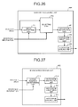
- FIG. 26 is a diagram that schematically illustrates a configuration of the division processing unit 46B according to the modified example 2.
- the division processing unit 46B includes functional units, such as the image converting unit 511, a selecting unit 512, the histogram generating unit 461, the histogram smoothing unit 462, and the histogram dividing unit 463.
- the image converting unit 511 may or may not have the selection function that is explained in the modified example 1.
- the selecting unit 512 receives input of an isolated area that is detected by the isolated-area detecting unit 45, an isolated area that is converted by the image converting unit 511, and the positional information on each isolated area.
- the selecting unit 512 selects an isolated area, which is to be output to the histogram dividing unit 463, from the input isolated areas on the basis of the positional information on each isolated area.
- the selecting unit 512 selects the isolated area that is converted by the image converting unit 511 with respect to the isolated area that is the area where deformation occurs, and it selects the isolated area that is detected by the isolated-area detecting unit 45 with respect to the isolated area that is the area where deformation does not occur.
- the areas G1 and G2, illustrated in FIG. 21 may be used as the area that serves as a reference for selection.
- the division processing unit 46B even if an isolated area is detected at a long distance and at an edge of the angle of view, the shape of a pixel group, included in the isolated area, may be corrected; thus, the isolated area may be easily divided in the same manner as in the modified example 1.
- FIG. 27 is a diagram that schematically illustrates a configuration of the division processing unit 46C according to the modified example 3.
- the division processing unit 46C includes functional units, such as a voting-position determining unit 513, a histogram generating unit 514, the histogram smoothing unit 462, and the histogram dividing unit 463.
- the voting-position determining unit 513 receives input of isolated areas that are detected by the isolated-area detecting unit 45 and the positional information on each isolated area. With regard to each isolated area, the voting-position determining unit 513 determines the voting position of each pixel (effective pixel) that is present in the isolated area. Here, the voting position specifies the position of the bin in the histogram in accordance with the disparity frequency of the effective pixel, i.e., the position of the abscissa on the second U map. Here, the voting-position determining unit 513 determines that the pixel location X new , which is calculated in accordance with the above-described Equation (6), is the voting position.
- the voting-position determining unit 513 relates the disparity frequency of an effective pixel and the voting position of the effective pixel and outputs them to the histogram generating unit 514.
- the histogram generating unit 514 generates a histogram for each isolated area on the basis of the disparity frequency and the voting position of the effective pixel, input from the voting-position determining unit 513.
- the result where the deformation, which occurs in an isolated area, has been corrected is applied to the histogram that is generated by the histogram generating unit 514. Therefore, the histogram dividing unit 463 may easily divide an isolated area by using the histogram that is generated by the histogram generating unit 514.
- a configuration may be such that, as the image capturing unit 10, a monocular distance-image camera is used, which is capable of acquiring image data (distance image) that includes the distance information indicating the distance (depth) from the object on a pixel by pixel basis.
- a configuration may be such that distance images may be acquired by using the combination of a distance measuring unit, such as a laser, and a commonly used monocular camera. If such a configuration is used, the distance from the object is proportional to the reciprocal of the disparity value d; therefore, the disparity image, the first U map, the second U map, or the like, may be generated on the basis of the distance image.
- the histogram generating unit 461 does not need to actually generate a histogram as an image.
- the histogram generating unit 461 may generate the numerical information that indicates the histogram, for example, as the disparity-frequency distribution information.
- any of the above-described apparatus, devices or units can be implemented as a hardware apparatus, such as a special-purpose circuit or device, or as a hardware/software combination, such as a processor executing a software program.
- any one of the above-described and other methods of the present invention may be embodied in the form of a computer program stored in any kind of storage medium.
- storage mediums include, but are not limited to, flexible disk, hard disk, optical discs, magneto-optical discs, magnetic tapes, nonvolatile memory, semiconductor memory, read-only-memory (ROM), etc.
- any one of the above-described and other methods of the present invention may be implemented by an application specific integrated circuit (ASIC), a digital signal processor (DSP) or a field programmable gate array (FPGA), prepared by interconnecting an appropriate network of conventional component circuits or by a combination thereof with one or more conventional general purpose microprocessors or signal processors programmed accordingly.
- ASIC application specific integrated circuit
- DSP digital signal processor
- FPGA field programmable gate array
- Processing circuitry includes a programmed processor, as a processor includes circuitry.
- a processing circuit also includes devices such as an application specific integrated circuit (ASIC), digital signal processor (DSP), field programmable gate array (FPGA) and conventional circuit components arranged to perform the recited functions.
- ASIC application specific integrated circuit
- DSP digital signal processor
- FPGA field programmable gate array
Landscapes
- Engineering & Computer Science (AREA)
- Physics & Mathematics (AREA)
- General Physics & Mathematics (AREA)
- Theoretical Computer Science (AREA)
- Multimedia (AREA)
- Computer Vision & Pattern Recognition (AREA)
- Image Analysis (AREA)
- Image Processing (AREA)
- Length Measuring Devices By Optical Means (AREA)
- Measurement Of Optical Distance (AREA)
- Traffic Control Systems (AREA)
Applications Claiming Priority (1)
| Application Number | Priority Date | Filing Date | Title |
|---|---|---|---|
| JP2015135574A JP6592991B2 (ja) | 2015-07-06 | 2015-07-06 | 物体検出装置、物体検出方法及びプログラム |
Publications (2)
| Publication Number | Publication Date |
|---|---|
| EP3115966A1 true EP3115966A1 (fr) | 2017-01-11 |
| EP3115966B1 EP3115966B1 (fr) | 2020-03-04 |
Family
ID=56683709
Family Applications (1)
| Application Number | Title | Priority Date | Filing Date |
|---|---|---|---|
| EP16177194.4A Active EP3115966B1 (fr) | 2015-07-06 | 2016-06-30 | Dispositif de détection d'objet, procédé de détection d'objet et programme informatique |
Country Status (2)
| Country | Link |
|---|---|
| EP (1) | EP3115966B1 (fr) |
| JP (1) | JP6592991B2 (fr) |
Cited By (2)
| Publication number | Priority date | Publication date | Assignee | Title |
|---|---|---|---|---|
| EP3540640A1 (fr) * | 2018-03-16 | 2019-09-18 | Ricoh Company, Ltd. | Appareil de traitement d'informations, système, corps mobile, procédé de traitement d'informations et programme |
| EP3716145A1 (fr) * | 2019-03-27 | 2020-09-30 | Kabushiki Kaisha Toyota Jidoshokki | Dispositif et procédé de détection d'objets |
Families Citing this family (5)
| Publication number | Priority date | Publication date | Assignee | Title |
|---|---|---|---|---|
| JP7306139B2 (ja) * | 2019-07-30 | 2023-07-11 | 株式会社リコー | 画像処理装置、物体認識装置、機器制御システム、画像処理方法およびプログラム |
| KR102430120B1 (ko) * | 2019-12-24 | 2022-08-05 | 동의대학교 산학협력단 | 스테레오 기반의 roi 검출 알고리즘의 성능을 향상시키는 방법 및 장치 |
| TW202305740A (zh) * | 2021-06-17 | 2023-02-01 | 日商新唐科技日本股份有限公司 | 物體檢測裝置、物體檢測方法及程式 |
| JP7138265B1 (ja) * | 2021-06-17 | 2022-09-15 | ヌヴォトンテクノロジージャパン株式会社 | 物体検知装置、物体検知方法およびプログラム |
| WO2024042607A1 (fr) * | 2022-08-23 | 2024-02-29 | 日立Astemo株式会社 | Dispositif de reconnaissance du monde extérieur et procédé de reconnaissance du monde extérieur |
Citations (1)
| Publication number | Priority date | Publication date | Assignee | Title |
|---|---|---|---|---|
| JP2014096005A (ja) | 2012-11-08 | 2014-05-22 | Hitachi Automotive Systems Ltd | 物体検出装置及び物体検出方法 |
Family Cites Families (2)
| Publication number | Priority date | Publication date | Assignee | Title |
|---|---|---|---|---|
| JP6150164B2 (ja) * | 2013-07-01 | 2017-06-21 | 株式会社リコー | 情報検出装置、移動体機器制御システム、移動体及び情報検出用プログラム |
| JP6519262B2 (ja) * | 2014-04-10 | 2019-05-29 | 株式会社リコー | 立体物検出装置、立体物検出方法、立体物検出プログラム、及び移動体機器制御システム |
-
2015
- 2015-07-06 JP JP2015135574A patent/JP6592991B2/ja not_active Expired - Fee Related
-
2016
- 2016-06-30 EP EP16177194.4A patent/EP3115966B1/fr active Active
Patent Citations (1)
| Publication number | Priority date | Publication date | Assignee | Title |
|---|---|---|---|---|
| JP2014096005A (ja) | 2012-11-08 | 2014-05-22 | Hitachi Automotive Systems Ltd | 物体検出装置及び物体検出方法 |
Non-Patent Citations (3)
| Title |
|---|
| BENJAMIN KORMANN ET AL: "STEREO VISION BASED VEHICLE DETECTION", VISIGRAPP 2010: INTERNATIONAL JOINT CONFERENCE ON COMPUTER VISION, IMAGING AND COMPUTER GRAPHICS THEORY AND APPLICATIONS, 17 May 2010 (2010-05-17), Angers, France, pages 431 - 438, XP055156426, Retrieved from the Internet <URL:http://ar.in.tum.de/pub/kormann2010visigrapp/kormann2010visigrapp.pdf> [retrieved on 20141203] * |
| TARAK GANDHI ET AL: "Vehicle Surround Capture: Survey of Techniques and a Novel Omni-Video-Based Approach for Dynamic Panoramic Surround Maps", IEEE TRANSACTIONS ON INTELLIGENT TRANSPORTATION SYSTEMS, IEEE, PISCATAWAY, NJ, USA, vol. 7, no. 3, 1 September 2006 (2006-09-01), pages 293 - 308, XP002659721, ISSN: 1524-9050, DOI: 10.1109/TITS.2006.880635 * |
| WEIMING HU ET AL: "Principal Axis-Based Correspondence between Multiple Cameras for People Tracking", IEEE TRANSACTIONS ON PATTERN ANALYSIS AND MACHINE INTELLIGENCE, IEEE COMPUTER SOCIETY, USA, vol. 28, no. 4, 1 April 2006 (2006-04-01), pages 663 - 671, XP001523374, ISSN: 0162-8828, DOI: 10.1109/TPAMI.2006.80 * |
Cited By (2)
| Publication number | Priority date | Publication date | Assignee | Title |
|---|---|---|---|---|
| EP3540640A1 (fr) * | 2018-03-16 | 2019-09-18 | Ricoh Company, Ltd. | Appareil de traitement d'informations, système, corps mobile, procédé de traitement d'informations et programme |
| EP3716145A1 (fr) * | 2019-03-27 | 2020-09-30 | Kabushiki Kaisha Toyota Jidoshokki | Dispositif et procédé de détection d'objets |
Also Published As
| Publication number | Publication date |
|---|---|
| EP3115966B1 (fr) | 2020-03-04 |
| JP2017016584A (ja) | 2017-01-19 |
| JP6592991B2 (ja) | 2019-10-23 |
Similar Documents
| Publication | Publication Date | Title |
|---|---|---|
| EP3115966B1 (fr) | Dispositif de détection d'objet, procédé de détection d'objet et programme informatique | |
| US10755116B2 (en) | Image processing apparatus, imaging apparatus, and device control system | |
| US10776946B2 (en) | Image processing device, object recognizing device, device control system, moving object, image processing method, and computer-readable medium | |
| EP3549055B1 (fr) | Dispositif de traitement d'informations, dispositif d'imagerie, système de commande d'appareil, procédé de traitement d'informations et produit de programme informatique | |
| US8977006B2 (en) | Target recognition system and target recognition method executed by the target recognition system | |
| US10832431B2 (en) | Image processing apparatus, object recognition apparatus, equipment control system, image processing method, and computer-readable recording medium | |
| US10776637B2 (en) | Image processing device, object recognizing device, device control system, image processing method, and computer-readable medium | |
| US9747524B2 (en) | Disparity value deriving device, equipment control system, movable apparatus, and robot | |
| US11691585B2 (en) | Image processing apparatus, imaging device, moving body device control system, image processing method, and program product | |
| JP6743882B2 (ja) | 画像処理装置、機器制御システム、撮像装置、画像処理方法及びプログラム | |
| US20200074212A1 (en) | Information processing device, imaging device, equipment control system, mobile object, information processing method, and computer-readable recording medium | |
| US10885351B2 (en) | Image processing apparatus to estimate a plurality of road surfaces | |
| EP3282389B1 (fr) | Appareil de traitement d'image, appareil de capture d'image, système de commande d'appareil de corps mobile, procédé de traitement d'image, et programme | |
| US10546383B2 (en) | Image processing device, object recognizing device, device control system, image processing method, and computer-readable medium | |
| CN111971682A (zh) | 路面检测装置、利用了路面检测装置的图像显示装置、利用了路面检测装置的障碍物检测装置、路面检测方法、利用了路面检测方法的图像显示方法以及利用了路面检测方法的障碍物检测方法 | |
| WO2011016257A1 (fr) | Dispositif de calcul de la distance pour un véhicule | |
| JP2023184572A (ja) | 電子機器、移動体、撮像装置、および電子機器の制御方法、プログラム、記憶媒体 | |
| JP2020126304A (ja) | 車外物体検出装置 | |
| EP3540643A1 (fr) | Appareil de traitement d'images et procédé de traitement d'images | |
| EP3287948B1 (fr) | Appareil de traitement d'images, système de commande d'appareil de corps mobile, procédé de traitement d'images et programme | |
| JP6943092B2 (ja) | 情報処理装置、撮像装置、機器制御システム、移動体、情報処理方法、及び、情報処理プログラム | |
| CN116736277A (zh) | 电子仪器、可移动设备、距离计算方法和存储介质 |
Legal Events
| Date | Code | Title | Description |
|---|---|---|---|
| PUAI | Public reference made under article 153(3) epc to a published international application that has entered the european phase |
Free format text: ORIGINAL CODE: 0009012 |
|
| STAA | Information on the status of an ep patent application or granted ep patent |
Free format text: STATUS: REQUEST FOR EXAMINATION WAS MADE |
|
| 17P | Request for examination filed |
Effective date: 20160630 |
|
| AK | Designated contracting states |
Kind code of ref document: A1 Designated state(s): AL AT BE BG CH CY CZ DE DK EE ES FI FR GB GR HR HU IE IS IT LI LT LU LV MC MK MT NL NO PL PT RO RS SE SI SK SM TR |
|
| AX | Request for extension of the european patent |
Extension state: BA ME |
|
| STAA | Information on the status of an ep patent application or granted ep patent |
Free format text: STATUS: EXAMINATION IS IN PROGRESS |
|
| 17Q | First examination report despatched |
Effective date: 20170818 |
|
| REG | Reference to a national code |
Ref country code: DE Ref legal event code: R079 Ref document number: 602016030920 Country of ref document: DE Free format text: PREVIOUS MAIN CLASS: G06T0007000000 Ipc: G06T0007110000 |
|
| GRAP | Despatch of communication of intention to grant a patent |
Free format text: ORIGINAL CODE: EPIDOSNIGR1 |
|
| STAA | Information on the status of an ep patent application or granted ep patent |
Free format text: STATUS: GRANT OF PATENT IS INTENDED |
|
| RIC1 | Information provided on ipc code assigned before grant |
Ipc: G06T 7/11 20170101AFI20190910BHEP |
|
| INTG | Intention to grant announced |
Effective date: 20191007 |
|
| GRAS | Grant fee paid |
Free format text: ORIGINAL CODE: EPIDOSNIGR3 |
|
| GRAA | (expected) grant |
Free format text: ORIGINAL CODE: 0009210 |
|
| STAA | Information on the status of an ep patent application or granted ep patent |
Free format text: STATUS: THE PATENT HAS BEEN GRANTED |
|
| AK | Designated contracting states |
Kind code of ref document: B1 Designated state(s): AL AT BE BG CH CY CZ DE DK EE ES FI FR GB GR HR HU IE IS IT LI LT LU LV MC MK MT NL NO PL PT RO RS SE SI SK SM TR |
|
| REG | Reference to a national code |
Ref country code: GB Ref legal event code: FG4D |
|
| REG | Reference to a national code |
Ref country code: CH Ref legal event code: EP |
|
| REG | Reference to a national code |
Ref country code: AT Ref legal event code: REF Ref document number: 1241258 Country of ref document: AT Kind code of ref document: T Effective date: 20200315 |
|
| REG | Reference to a national code |
Ref country code: DE Ref legal event code: R096 Ref document number: 602016030920 Country of ref document: DE |
|
| REG | Reference to a national code |
Ref country code: IE Ref legal event code: FG4D |
|
| PG25 | Lapsed in a contracting state [announced via postgrant information from national office to epo] |
Ref country code: FI Free format text: LAPSE BECAUSE OF FAILURE TO SUBMIT A TRANSLATION OF THE DESCRIPTION OR TO PAY THE FEE WITHIN THE PRESCRIBED TIME-LIMIT Effective date: 20200304 Ref country code: RS Free format text: LAPSE BECAUSE OF FAILURE TO SUBMIT A TRANSLATION OF THE DESCRIPTION OR TO PAY THE FEE WITHIN THE PRESCRIBED TIME-LIMIT Effective date: 20200304 Ref country code: NO Free format text: LAPSE BECAUSE OF FAILURE TO SUBMIT A TRANSLATION OF THE DESCRIPTION OR TO PAY THE FEE WITHIN THE PRESCRIBED TIME-LIMIT Effective date: 20200604 |
|
| REG | Reference to a national code |
Ref country code: NL Ref legal event code: MP Effective date: 20200304 |
|
| PG25 | Lapsed in a contracting state [announced via postgrant information from national office to epo] |
Ref country code: BG Free format text: LAPSE BECAUSE OF FAILURE TO SUBMIT A TRANSLATION OF THE DESCRIPTION OR TO PAY THE FEE WITHIN THE PRESCRIBED TIME-LIMIT Effective date: 20200604 Ref country code: LV Free format text: LAPSE BECAUSE OF FAILURE TO SUBMIT A TRANSLATION OF THE DESCRIPTION OR TO PAY THE FEE WITHIN THE PRESCRIBED TIME-LIMIT Effective date: 20200304 Ref country code: SE Free format text: LAPSE BECAUSE OF FAILURE TO SUBMIT A TRANSLATION OF THE DESCRIPTION OR TO PAY THE FEE WITHIN THE PRESCRIBED TIME-LIMIT Effective date: 20200304 Ref country code: GR Free format text: LAPSE BECAUSE OF FAILURE TO SUBMIT A TRANSLATION OF THE DESCRIPTION OR TO PAY THE FEE WITHIN THE PRESCRIBED TIME-LIMIT Effective date: 20200605 Ref country code: HR Free format text: LAPSE BECAUSE OF FAILURE TO SUBMIT A TRANSLATION OF THE DESCRIPTION OR TO PAY THE FEE WITHIN THE PRESCRIBED TIME-LIMIT Effective date: 20200304 |
|
| REG | Reference to a national code |
Ref country code: LT Ref legal event code: MG4D |
|
| PG25 | Lapsed in a contracting state [announced via postgrant information from national office to epo] |
Ref country code: NL Free format text: LAPSE BECAUSE OF FAILURE TO SUBMIT A TRANSLATION OF THE DESCRIPTION OR TO PAY THE FEE WITHIN THE PRESCRIBED TIME-LIMIT Effective date: 20200304 |
|
| PG25 | Lapsed in a contracting state [announced via postgrant information from national office to epo] |
Ref country code: EE Free format text: LAPSE BECAUSE OF FAILURE TO SUBMIT A TRANSLATION OF THE DESCRIPTION OR TO PAY THE FEE WITHIN THE PRESCRIBED TIME-LIMIT Effective date: 20200304 Ref country code: PT Free format text: LAPSE BECAUSE OF FAILURE TO SUBMIT A TRANSLATION OF THE DESCRIPTION OR TO PAY THE FEE WITHIN THE PRESCRIBED TIME-LIMIT Effective date: 20200729 Ref country code: SM Free format text: LAPSE BECAUSE OF FAILURE TO SUBMIT A TRANSLATION OF THE DESCRIPTION OR TO PAY THE FEE WITHIN THE PRESCRIBED TIME-LIMIT Effective date: 20200304 Ref country code: RO Free format text: LAPSE BECAUSE OF FAILURE TO SUBMIT A TRANSLATION OF THE DESCRIPTION OR TO PAY THE FEE WITHIN THE PRESCRIBED TIME-LIMIT Effective date: 20200304 Ref country code: IS Free format text: LAPSE BECAUSE OF FAILURE TO SUBMIT A TRANSLATION OF THE DESCRIPTION OR TO PAY THE FEE WITHIN THE PRESCRIBED TIME-LIMIT Effective date: 20200704 Ref country code: SK Free format text: LAPSE BECAUSE OF FAILURE TO SUBMIT A TRANSLATION OF THE DESCRIPTION OR TO PAY THE FEE WITHIN THE PRESCRIBED TIME-LIMIT Effective date: 20200304 Ref country code: ES Free format text: LAPSE BECAUSE OF FAILURE TO SUBMIT A TRANSLATION OF THE DESCRIPTION OR TO PAY THE FEE WITHIN THE PRESCRIBED TIME-LIMIT Effective date: 20200304 Ref country code: LT Free format text: LAPSE BECAUSE OF FAILURE TO SUBMIT A TRANSLATION OF THE DESCRIPTION OR TO PAY THE FEE WITHIN THE PRESCRIBED TIME-LIMIT Effective date: 20200304 Ref country code: CZ Free format text: LAPSE BECAUSE OF FAILURE TO SUBMIT A TRANSLATION OF THE DESCRIPTION OR TO PAY THE FEE WITHIN THE PRESCRIBED TIME-LIMIT Effective date: 20200304 |
|
| REG | Reference to a national code |
Ref country code: AT Ref legal event code: MK05 Ref document number: 1241258 Country of ref document: AT Kind code of ref document: T Effective date: 20200304 |
|
| REG | Reference to a national code |
Ref country code: DE Ref legal event code: R097 Ref document number: 602016030920 Country of ref document: DE |
|
| PLBE | No opposition filed within time limit |
Free format text: ORIGINAL CODE: 0009261 |
|
| STAA | Information on the status of an ep patent application or granted ep patent |
Free format text: STATUS: NO OPPOSITION FILED WITHIN TIME LIMIT |
|
| PG25 | Lapsed in a contracting state [announced via postgrant information from national office to epo] |
Ref country code: IT Free format text: LAPSE BECAUSE OF FAILURE TO SUBMIT A TRANSLATION OF THE DESCRIPTION OR TO PAY THE FEE WITHIN THE PRESCRIBED TIME-LIMIT Effective date: 20200304 Ref country code: AT Free format text: LAPSE BECAUSE OF FAILURE TO SUBMIT A TRANSLATION OF THE DESCRIPTION OR TO PAY THE FEE WITHIN THE PRESCRIBED TIME-LIMIT Effective date: 20200304 Ref country code: DK Free format text: LAPSE BECAUSE OF FAILURE TO SUBMIT A TRANSLATION OF THE DESCRIPTION OR TO PAY THE FEE WITHIN THE PRESCRIBED TIME-LIMIT Effective date: 20200304 Ref country code: MC Free format text: LAPSE BECAUSE OF FAILURE TO SUBMIT A TRANSLATION OF THE DESCRIPTION OR TO PAY THE FEE WITHIN THE PRESCRIBED TIME-LIMIT Effective date: 20200304 |
|
| REG | Reference to a national code |
Ref country code: CH Ref legal event code: PL |
|
| 26N | No opposition filed |
Effective date: 20201207 |
|
| PG25 | Lapsed in a contracting state [announced via postgrant information from national office to epo] |
Ref country code: PL Free format text: LAPSE BECAUSE OF FAILURE TO SUBMIT A TRANSLATION OF THE DESCRIPTION OR TO PAY THE FEE WITHIN THE PRESCRIBED TIME-LIMIT Effective date: 20200304 Ref country code: SI Free format text: LAPSE BECAUSE OF FAILURE TO SUBMIT A TRANSLATION OF THE DESCRIPTION OR TO PAY THE FEE WITHIN THE PRESCRIBED TIME-LIMIT Effective date: 20200304 |
|
| PG25 | Lapsed in a contracting state [announced via postgrant information from national office to epo] |
Ref country code: LU Free format text: LAPSE BECAUSE OF NON-PAYMENT OF DUE FEES Effective date: 20200630 |
|
| REG | Reference to a national code |
Ref country code: BE Ref legal event code: MM Effective date: 20200630 |
|
| PG25 | Lapsed in a contracting state [announced via postgrant information from national office to epo] |
Ref country code: IE Free format text: LAPSE BECAUSE OF NON-PAYMENT OF DUE FEES Effective date: 20200630 Ref country code: CH Free format text: LAPSE BECAUSE OF NON-PAYMENT OF DUE FEES Effective date: 20200630 Ref country code: LI Free format text: LAPSE BECAUSE OF NON-PAYMENT OF DUE FEES Effective date: 20200630 |
|
| PG25 | Lapsed in a contracting state [announced via postgrant information from national office to epo] |
Ref country code: BE Free format text: LAPSE BECAUSE OF NON-PAYMENT OF DUE FEES Effective date: 20200630 |
|
| PGFP | Annual fee paid to national office [announced via postgrant information from national office to epo] |
Ref country code: DE Payment date: 20210618 Year of fee payment: 6 Ref country code: FR Payment date: 20210622 Year of fee payment: 6 |
|
| PGFP | Annual fee paid to national office [announced via postgrant information from national office to epo] |
Ref country code: GB Payment date: 20210625 Year of fee payment: 6 |
|
| PG25 | Lapsed in a contracting state [announced via postgrant information from national office to epo] |
Ref country code: TR Free format text: LAPSE BECAUSE OF FAILURE TO SUBMIT A TRANSLATION OF THE DESCRIPTION OR TO PAY THE FEE WITHIN THE PRESCRIBED TIME-LIMIT Effective date: 20200304 Ref country code: MT Free format text: LAPSE BECAUSE OF FAILURE TO SUBMIT A TRANSLATION OF THE DESCRIPTION OR TO PAY THE FEE WITHIN THE PRESCRIBED TIME-LIMIT Effective date: 20200304 Ref country code: CY Free format text: LAPSE BECAUSE OF FAILURE TO SUBMIT A TRANSLATION OF THE DESCRIPTION OR TO PAY THE FEE WITHIN THE PRESCRIBED TIME-LIMIT Effective date: 20200304 |
|
| PG25 | Lapsed in a contracting state [announced via postgrant information from national office to epo] |
Ref country code: MK Free format text: LAPSE BECAUSE OF FAILURE TO SUBMIT A TRANSLATION OF THE DESCRIPTION OR TO PAY THE FEE WITHIN THE PRESCRIBED TIME-LIMIT Effective date: 20200304 Ref country code: AL Free format text: LAPSE BECAUSE OF FAILURE TO SUBMIT A TRANSLATION OF THE DESCRIPTION OR TO PAY THE FEE WITHIN THE PRESCRIBED TIME-LIMIT Effective date: 20200304 |
|
| REG | Reference to a national code |
Ref country code: DE Ref legal event code: R119 Ref document number: 602016030920 Country of ref document: DE |
|
| GBPC | Gb: european patent ceased through non-payment of renewal fee |
Effective date: 20220630 |
|
| PG25 | Lapsed in a contracting state [announced via postgrant information from national office to epo] |
Ref country code: FR Free format text: LAPSE BECAUSE OF NON-PAYMENT OF DUE FEES Effective date: 20220630 |
|
| PG25 | Lapsed in a contracting state [announced via postgrant information from national office to epo] |
Ref country code: GB Free format text: LAPSE BECAUSE OF NON-PAYMENT OF DUE FEES Effective date: 20220630 Ref country code: DE Free format text: LAPSE BECAUSE OF NON-PAYMENT OF DUE FEES Effective date: 20230103 |