EP3115936A1 - Printing apparatus and printing method - Google Patents
Printing apparatus and printing method Download PDFInfo
- Publication number
- EP3115936A1 EP3115936A1 EP16178100.0A EP16178100A EP3115936A1 EP 3115936 A1 EP3115936 A1 EP 3115936A1 EP 16178100 A EP16178100 A EP 16178100A EP 3115936 A1 EP3115936 A1 EP 3115936A1
- Authority
- EP
- European Patent Office
- Prior art keywords
- printing
- data
- sections
- color
- driving controller
- Prior art date
- Legal status (The legal status is an assumption and is not a legal conclusion. Google has not performed a legal analysis and makes no representation as to the accuracy of the status listed.)
- Granted
Links
Images



Classifications
-
- G—PHYSICS
- G06—COMPUTING OR CALCULATING; COUNTING
- G06K—GRAPHICAL DATA READING; PRESENTATION OF DATA; RECORD CARRIERS; HANDLING RECORD CARRIERS
- G06K15/00—Arrangements for producing a permanent visual presentation of the output data, e.g. computer output printers
- G06K15/02—Arrangements for producing a permanent visual presentation of the output data, e.g. computer output printers using printers
- G06K15/18—Conditioning data for presenting it to the physical printing elements
- G06K15/1848—Generation of the printable image
- G06K15/1856—Generation of the printable image characterized by its workflow
- G06K15/1857—Generation of the printable image characterized by its workflow involving parallel processing in the same printing apparatus
-
- H—ELECTRICITY
- H04—ELECTRIC COMMUNICATION TECHNIQUE
- H04N—PICTORIAL COMMUNICATION, e.g. TELEVISION
- H04N1/00—Scanning, transmission or reproduction of documents or the like, e.g. facsimile transmission; Details thereof
- H04N1/46—Colour picture communication systems
-
- H—ELECTRICITY
- H04—ELECTRIC COMMUNICATION TECHNIQUE
- H04N—PICTORIAL COMMUNICATION, e.g. TELEVISION
- H04N1/00—Scanning, transmission or reproduction of documents or the like, e.g. facsimile transmission; Details thereof
- H04N1/46—Colour picture communication systems
- H04N1/50—Picture reproducers
Definitions
- ink jet printers serving as printing apparatuses have achieved various printing forms through the use of various representation means for making representations on various printing media.
- ink jet printer has been extensively used in commercial-use, mid-size printers supporting the production of articles, such as posters, signboards, promotion goods, wrapping paper, and clothing articles, and in industrial-use, large-size printers built in production lines for products.
- technologies that enable realization of not only higher-quality printing but also higher-speed printing for the purpose of the increase of productivity have been required.
- an image recording apparatus (printing apparatus) is disclosed in JP-A-7-327117 .
- this image recording apparatus receives image data (printing data) from a host apparatus, and allows a recording head to perform scanning operation to perform recording for each band on the basis of the received image data.
- This image recording apparatus makes an effective use of memory and any other resource, and reduces the number of handshaking communication operations for the transfer of the image data to reduce a communication time.
- the image recording apparatus is capable of recording an image at a high speed.
- a printing apparatus includes a plurality of printing sections each associated with a corresponding one of printing colors of inks used in the printing apparatus and configured to discharge a corresponding one of the inks onto a printing medium to execute a printing process; a printing medium movement section configured to move the printing medium relatively to the printing sections; a driving controller configured to drive control the printing sections and the printing medium movement section; a plurality of printing data controllers configured to, for each of the printing colors, generate a single-color printing data on a basis of a set of full-color printing data associated with an image, a target of printing, and set a set of printing unit data resulting from dividing the set of single-color printing data, into a corresponding one of the printing sections; and a communication bus forming a bus-shaped network and coupled to the driving controller and the printing data controllers to provide information communication using no handshaking communication.
- a printing apparatus includes a plurality of printing sections each associated with a corresponding one of printing colors of inks used in the printing apparatus and configured to discharge a corresponding one of the inks onto a printing medium to execute a printing process; a printing medium movement section configured to move the printing medium relatively to the printing sections; a driving controller configured to drive control the printing sections and the printing medium movement section; a plurality of printing data controllers configured to, for each of the printing colors, generate a single-color printing data on a basis of a set of full-color printing data associated with an image, a target of printing, and set a set of printing unit data resulting from dividing the set of single-color printing data, into a corresponding one of the printing sections; and a communication bus forming a bus-shaped network and coupled to the driving controller and the printing data controllers to provide information communication.
- a pair of two sequential processes is repeatedly performed, a prior one of the two sequential processes being a process in which, upon completion of the setting of, for the each printing color, the set of printing unit data into the corresponding one of the printing sections, the printing data controllers transmit a piece of data setting completion information to the driving controller via the communication bus, a subsequent one of the two sequential processes being a process in which, upon receipt of the piece of data setting completion information for each of all of the printing colors from all of the printing data controllers, coupled to the communication bus, the driving controller drive controls the printing sections and the printing medium movement section on a basis of the received piece of data setting completion for the each of all of the printing colors.
- the handshaking communication is performed to perform the timing control between the driving controller and the printing sections
- the handshaking communication is performed between the driving controller and the plurality of printing sections, that is, between one point and multi-points, and thus, the number of processes for the handshaking communication is linearly increased.
- the handshaking communication is not performed, even when the number of the kinds of used inks is increased, the occurrence of a situation in which, with this increase, a processing time is linearly increased is eliminated.
- a transmission control/Internet protocol (TCP/IP) is employed as a communication protocol for the information communication provided by the communication bus.
- the TCP/IP is a high-versatility communication protocol
- the employment of the TCP/IP enables realization of constituting a printing apparatus more suitably.
- a printing method for a printing apparatus includes executing, by each of printing sections each associated with a corresponding one of printing colors of inks used in the printing apparatus, a printing process by discharging a corresponding one of the inks onto a printing medium; moving, by a printing medium movement section, the printing medium relatively to the printing sections; driving control, by a driving controller, the printing sections and the printing medium movement section; for each of the printing colors, generating, by printing data controllers, a single-color printing data on a basis of a set of full-color printing data associated with an image, a target of printing, and setting, by the printing data controllers, a set of printing unit data resulting from dividing the set of single-color printing data, into a corresponding one of the printing sections; and performing information communication between the driving controller and the printing data controllers using no handshaking communication, via a communication bus forming a bus-shaped network and coupled to the driving controller and the printing data controllers.
- timing control is performed through the information communication, via the communication bus, on the setting of, for the each printing color, the set of printing unit data into the corresponding one of the printing sections, and on the driving control of, by the driving controller, the printing sections and the printing medium movement section.
- the driving controller performs timing control on the setting of, for the each printing color, the set of printing unit data into the corresponding one of the printing sections, and on the driving control of, by the driving controller, the printing sections and the printing medium movement section.
- This timing control is performed through the information communication, via the communication bus.
- no handshaking communication is performed between the driving controller and the printing data controllers. For this reason, the reduction of the efficiency of printing processing due to the handshaking communication (for example, due to periods of time for waiting for replies) is eliminated.
- the handshaking communication is performed to perform the timing control between the driving controller and the printing sections
- the handshaking communication is performed between the driving controller and the plurality of printing sections, that is, between one point between multi-points, and thus, the number of processes for the handshaking communication is linearly increased.
- the handshaking communication is not performed, even when the number of the kinds of used inks is increased, the occurrence of a situation in which, with this increase, a processing time is linearly increased is eliminated.
- a printing method for a printing apparatus includes executing, by each of printing sections each associated with a corresponding one of printing colors of inks used in the printing apparatus, a printing process by discharging a corresponding one of the inks onto a printing medium; moving, by a printing medium movement section, the printing medium relatively to the printing sections; driving control, by a driving controller, the printing sections and the printing medium movement section; for each of the printing colors, generating, by printing data controllers, a single-color printing data on a basis of a set of full-color printing data associated with an image, a target of printing, and setting, by the printing data controllers, a set of printing unit data resulting from dividing the set of single-color printing data, into a corresponding one of the printing sections; and performing information communication between the driving controller and the printing data controllers, via a communication bus forming a bus-shaped network and coupled to the driving controller and the printing data controllers.
- a pair of two sequential processes is repeatedly performed, a prior one of the two sequential processes being a process in which, upon completion of the setting of, for the each printing color, the set of printing unit data into the corresponding one of the printing sections, a piece of data setting completion information is transmitted by the printing data controllers to the driving controller via the communication bus, a subsequent one of the two sequential processes being a process in which, upon receipt of the piece of data setting completion information for each of all of the printing colors from all of the printing data controllers, coupled to the communication bus, driving control of the printing sections and the printing medium movement section is performed by the driving controller on a basis of the received piece of data setting completion for the each of all of the printing colors.
- the driving controller performs timing control on the setting of, for the each printing color, the set of printing unit data into the corresponding one of the printing sections, and on the driving control of, by the driving controller, the printing sections and the printing medium movement section.
- This timing control is performed through the information communication, via the communication bus.
- the printing data controllers upon completion of the setting of, for the each printing color, the set of printing unit data into the corresponding one of the printing sections, transmit a piece of data setting completion information to the driving controller via the communication bus, and upon receipt of the piece of data setting completion information for each of all of the printing colors from all of the printing data controllers, coupled to the communication bus, the driving controller drive controls the printing sections and the printing medium movement section on the basis of the received piece of data setting completion for the each of all of the printing colors.
- the handshaking communication that is, inquiries from the driving control to the individual printing controllers and replies to the inquiries, is not made.
- the handshaking communication is performed to perform the timing control between the driving controller and the printing sections
- the handshaking communication is performed between the driving controller and the plurality of printing sections, that is, between one point between multi-points, and thus, the number of processes for the handshaking communication is linearly increased.
- the handshaking communication is not performed, even when the number of the kinds of used inks is increased, the occurrence of a situation in which, with this increase, a processing time is linearly increased is eliminated.
- a Z-axis direction corresponds to an upward and downward direction
- a +Z direction corresponds to an upward direction
- a Y-axis direction corresponds to a frontward and backward direction
- a +Y direction corresponds to a frontward direction
- an X-axis direction corresponds to a leftward and rightward direction
- a +X direction corresponds to a leftward direction
- an X-Y plane corresponds to a horizontal plane.
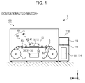
- Fig. 1 is a front view of a printing system 9, a printing system in a conventional technology, illustrating the configuration of the printing system 9 including a printing apparatus 109.
- Fig. 2 is a block diagram of the printing system 9.
- the printing system 9 includes the printing apparatus 109 and a personal computer 110 (hereinafter referred to as a PC 110).
- the personal computer 110 is coupled with the printing apparatus 109.
- the printing apparatus 109 is an ink jet printer configured to execute printing of a desired printing image (hereinafter also referred to as just an image) on a printing medium 5, having a long size and supplied in a wound, roll-shaped state, on the basis of printing data received from the PC 110.
- PC 110 Personal Computer
- the PC 110 includes a printer controller 111, an input section 112, a display section 113, a storage section 114, and any other section, and controls a print job in accordance with which the printing apparatus 109 executes printing.
- the printer controller 111 includes a CPU (arithmetic operation unit) and storage media, such as RAM and ROM, (these components being omitted from illustration), and performs concentrated management of the entire printing system 9.
- CPU central processing unit
- storage media such as RAM and ROM, (these components being omitted from illustration), and performs concentrated management of the entire printing system 9.
- the input section 112 corresponds to information input means serving as human interfaces, and specifically corresponds to ports to which information input devices, such as a keyboard, are coupled.
- the display section 113 corresponds to an information display means (display) serving as a human interface, and displays thereon information input from the input section 112, images to be printed by the printing apparatus 109, information in relation to a print job, and any other kind of information.
- display information display means
- the storage section 114 corresponds to rewritable storage media, such as a hard disc drive (HDD) and a memory card, and stores therein software executed by the PC 110 (i.e., programs executed by the printer controller 111), images to be printed, information in relation to a print job, and any other information.
- software executed by the PC 110 i.e., programs executed by the printer controller 111
- images to be printed information in relation to a print job, and any other information.
- the software executed by the PC 110 includes general image processing application software (hereinafter referred to as an application) and printer driver software (hereinafter referred to as a printer driver).
- application general image processing application software
- printer driver software hereinafter referred to as a printer driver
- the printing apparatus 109 includes a printing section 10, a printing medium movement section 20, a controller 30, and any other section. Upon receipt of printing data from the PC 110, the printing apparatus 109 allows the controller 30 to control the printing medium movement section 20 to execute printing of an image (forming of an image) onto the printing medium 5.
- the printing data is data for use in forming an image, and is data having been subjected to processing for converting general RGB digital image information obtained through, for example, a digital camera into data printable by the application and the printer driver, which are installed in the PC 110.
- the printing data includes commands for controlling the printing apparatus 109.
- the printing section 10 includes a printing head 11, a printing head controller 12, and any other component.
- the printing medium movement section 20 includes a main-scanning section 40, a sub-scanning section 50 and any other section.
- the main-scanning section 40 includes a carriage 41, a guide shaft 42, a carriage motor (omitted from illustration), and any other component.
- the sub-scanning section 50 includes a feed section 51, a container section 52, transport rollers 53, a platen 55, and any other component.
- the printing head 11 includes a plurality of nozzles (nozzle rows) through which printing inks (hereinafter referred to as inks) are ejected in the form of liquid droplets (hereinafter also referred to as ink droplets).
- the printing head 11 is mounted in the carriage 41 and reciprocates in a scanning direction (the Y-axis direction shown in Fig. 1 ) with the carriage 41, which moves in the scanning direction. While moving in the scanning direction, the printing head 11 ejects ink droplets onto the printing medium 5, supported by the platen 55, under the control of the controller 30, and as a result, dot rows (raster lines) along the scanning direction are formed on the printing medium 5.
- a piezo method is employed as a preferred example of a method for ejecting ink droplets (i.e., an ink jet method).
- This piezo method is a method that allows a piezoelectric element (a piezo element) to apply a pressure in accordance with a printing information signal to an ink stored in a pressure chamber to allow an ink droplet to be ejected (discharged) through a nozzle communicating with the pressure chamber so as to execute a printing operation.
- the method of discharging ink droplets is not limited to this method but may be a different method that allows liquid-drop shaped inks to be ejected onto a printing medium to allow dot clusters to be formed on the printing medium.
- a different method include, but are not limited to, a method that allows a small pump to apply a pressure to an ink and allows a liquid crystal vibrator or any other vibrator to mechanically vibrate a nozzle so as to cause an ink droplet to be ejected through the nozzle, and a method that, in accordance with a recording information signal, allows a minute electrode to heat an ink to cause a bubble to be formed in the ink to cause an ink droplet to be ejected so as to allow a recording operation to be executed (this method being called a thermal jet method).
- the printing medium movement section 20 (including the main-scanning section 40 and the sub-scanning section 50) allows the printing medium 5 to move relatively to the printing section 10 under the control of the controller 30.
- the guide shaft 42 extends in the scanning direction and supports the carriage 41 in a state in which the carriage 41 is slidably in contact with the guide shaft 42.
- the carriage motor is a drive source for allowing the carriage 41 to reciprocate along the guide shaft 42. That is, the main-scanning section 40 (including the carriage 41, the guide shaft 42, and the carriage motor) allows the carriage 41 (i.e., the printing head 11) to move in the scanning direction, along the guide shaft 42, under the control of the controller 30.
- the feed section 51 supports a reel around which the printing medium 5 is wound in a roll shape, in a way that allows the reel to freely rotate, and feeds out the printing medium 5 to a transport path.
- the container section 52 supports a reel for winding the printing medium 5, in a way that allows the reel to freely rotate, and winds up the recording medium 5, having been subjected to printing, from the transport path.
- the transport rollers 53 include a drive roller configured to move the printing medium 5 in a sub-scanning direction (i.e., the X-axis direction shown in Fig. 1 ) intersecting with the main-scanning direction, a driven roller configured to rotate in conjunction with the movement of the printing medium 5, and any other component. Further, the transport rollers 53 form a transport path along which the printing medium 5 is transported from the feed section 51 to the container section 52 via a printing region of the printing section 10. This printing region is a region which is located on the upper surface of the platen 55 and above which the printing head 11 moves during a scanning operation.
- the controller 30 includes an interface section 31, a CPU 32, a memory 33, a driving controller 34, a printing data setting section 35, and any other section, and controls the printing apparatus 109.
- the interface section 31 performs data transmission/reception between the PC 110 and the printing apparatus 109.
- the CPU 32 is an arithmetic processing device for controlling the entire printing apparatus 109.
- the memory 33 is a storage medium that retains an area for storing therein programs executed by the CPU 32, a work area for use in the execution of the programs, and any other area, and is constituted by memory elements, such as RAM and EEPROM.
- the CPU 32 is configured to, via the driving controller 34, control the printing medium movement section 20 (the main-scanning section 40 and the sub-scanning section 50) and the printing portion 10 (the printing head 11) in accordance with the programs stored in the memory 33 and printing data received from the PC 110 and stored in the memory 33, and further, the CPU 32 is configured to, via the printing data setting section 35, sequentially transmit raster data described below to the printing head controller 12 on the basis of the printing data stored in the memory 33.
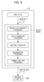
- Fig. 3 is a diagram illustrating processes performed by the printer driver.
- the printer driver Upon receipt of a set of image data, such as a set of text data or a set of full-color image data, from an application, the printer driver converts the set of image data into a set of printing data having a format interpretable by the printing apparatus 109, and outputs the set of printing data to the printing apparatus 109.
- the printing driver When converting the set of image data from the application into the set of printing data, the printing driver performs resolution conversion processing, color conversion processing, halftone processing, rasterization processing, command addition processing, and any other processing.
- the resolution conversion processing is processing for converting the resolution of the set of image data output from the application into a resolution (a printing resolution) at which printing is to be executed onto the printing medium 5.
- a resolution a printing resolution
- the resolution conversion processing converts a set of image data having been received from the application and having a vector format into a set of image data having a bit map format and having a resolution of 720 x 720 dpi.
- the set of image data after the resolution conversion processing is composed of pieces of pixel data each associated with a corresponding one of pixels arranged in a matrix shape.
- Each of the pixels has a combination of grayscale levels each being one of, for example, 256 grayscale levels in a corresponding one of RGB-color spaces. That is, each piece of image data constituting the set of image data after the resolution conversion processing indicates a combination of grayscale levels that is associated with a corresponding pixel.
- a block of pieces of image data each associated with a corresponding one of pixels forming one row and arranged in a predetermined direction among the pixels arranged in the matrix shape is called a block of raster data.
- the predetermined direction in which the pixels forming one row and associated with a block of raster data are arranged, corresponds to the movement direction (the scanning direction), in which the printing head 11 moves when an image is printed.
- the color conversion processing is processing for converting RGB data into data in spaces of a CMYK-color system.
- the CMYK color corresponds to cyan (C), magenta (M), yellow (Y), and black (K), and a set of image data in the spaces of the CMYK-color system is a set of data corresponding to the colors of inks included in the printing apparatus 109.
- the printer driver when the printing apparatus 109 uses ten kinds of inks in the CMYK-color system, the printer driver generates a set of image data in ten-dimensional spaces of the CMYK-color system.
- the halftone processing is processing for converting a set of image data based on a high grayscale level (256 grayscale levels) into a set of data based on a grayscale level that is low enough for the formation by the printing apparatus 109.
- each piece of data indicating a combination of grayscale levels each being one of the 256 grayscale levels is converted into a piece of data indicating a combination of grayscale levels each being one of two grayscale levels represented by one bit of data, or a combination of grayscale levels each being one of four grayscale levels represented by two bits of data.
- a set of image data after the halftone processing is a set of data based on image data represented by one bit or two bits of data, and this set of data becomes a set of pieces of data each indicating a formation of a dot corresponding to each pixel (i.e., indicating the presence or absence of a dot or the size of a dot).
- each piece of image data is composed of two bits (indicating four grayscales)
- the formation of a corresponding dot is converted into one of four stages: a first one being a stage corresponding to a grayscale level [00] and indicating the formation of no dot; a second one being a stage corresponding to a grayscale level [01] and indicating the formation of a small-size dot; a third one being a stage corresponding to a grayscale level [10] and indicating the formation of a middle-size dot; and a fourth one being a stage corresponding to a grayscale level [11] and indicating the formation of a large-size dot.
- the printer driver determines a dot generation ratio for each of the dot sizes, and then, generates a set of image data using a dither method or an error diffusion method to allow the printing apparatus 109 to form dots so as to allow the dots to be dispersed.
- the rasterization processing is processing for rearranging pieces of image data arranged in a matrix shape, in accordance with dot formation order in a printing execution. For example when, in a printing execution, some dot formation processes resulting from dividing dot formation processing are performed, sets of image data each associated with a corresponding one of the dot formation processes are extracted, and pieces of image data constituting each of the sets of image data are rearranged in accordance with the dot formation order.
- the dot formation order in a printing execution differs depending on the kind of printing method, and thus, the rasterization processing is performed in accordance with the kind of printing method.
- the command addition processing is processing for adding command data to a set of data having been subjected to the rasterization processing.
- a non-limiting example of the command data includes transportation data specifying a transportation speed of a medium.
- a set of printing data having been generated through the above pieces of processing is transmitted to the printing apparatus 109 by the printer driver.
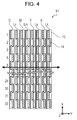
- Fig. 4 is a plan view of the printing head 11 illustrating the configuration of the printing head 11.
- the printing head 11 is constituted as an aggregate obtained by binding up eight ink discharging heads 13 in the scanning direction (the Y-axis direction).
- Each of the eight ink discharging heads 13 is associated with a corresponding one of the above eight colors, cyan (C), magenta (M), yellow (Y), black (K), light cyan (Lc), light magenta (Lm), light yellow (Ly), and light black (Lk).
- Each of the ink discharging heads 13 includes thirty two nozzle chips 14.
- the nozzle chips 14 are arranged in a zig-zag shape so as to form two rows extending in the X-axis direction.
- Each of the nozzle chips 14 includes two rows each consisting of 400 through-hole shaped nozzles that are formed at intervals of 1/360 inches.
- This configuration enables the printing head 11 to form 25000 dots colored in each of the eight colors and arranged at pitches of 1/720 inches (i.e., 720 dpi) in the sub-scanning direction (the X-axis direction).
- the printing apparatus 109 repeats a pass that allows the inks to be discharged in accordance with raster data based on printing data having been generated from image data to form an image corresponding to the image data on the printing medium 5.
- a set of pieces of raster data used for a printing execution for each pass is referred to as a block of printing unit data.
- pieces of raster data corresponding to a plurality of passes may be handled as a block of printing unit data depending on the capacity of the buffer memory included in the printing head controller 12 (that is, in the case where the buffer memory included in the printing head controller 12 has a capacity enough to store such pieces of raster data corresponding to a plurality of passes).
- a period of time required to generate each block of printing unit data that is associated with dots per one pass, and set the generated each block of printing unit data into the printing section 10 may be longer than a period of time required to execute printing during one pass (i.e., the sum of a period of time required to allow the printing head 11 to perform scanning operation during one pass and a period of time required to move the printing medium 5 in the sub-scanning direction by a predetermined amount).
- a period of waiting time between succeeding passes is made longer, and this long period of waiting time may adversely affect the quality of printing and/or may make a period of printing time longer than a desired time.
- this embodiment is configured such that the processing for generating and setting each block of printing unit data is distributed into a plurality of distributed processes that are concurrently executed, preferably so as not to make a period of time required to set the each block of printing unit data longer than a period of time required to perform the scanning operation by the printing head 11 during one pass.
- the period of time required to set the each block of printing unit data is the sum of a period of time required to allow the each block of printing unit data to be distributed to and subjected to the plurality of distributed processes, and a period of time required to perform a process of causing the timing points of the plurality distributed processes to coincide with one another.
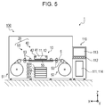
- Fig. 5 is a front view of a printing system 1, a printing system according to embodiment 1, illustrating the configuration of the printing system 1 including a printing apparatus 100.
- Fig. 6 is a block diagram of the printing system 1.
- the printing system 1 includes the printing apparatus 100 and a personal computer 110.
- the personal computer 110 is coupled to the printing apparatus 100.
- the printing apparatus 100 is configured to, in order to reduce a period of time required to generate each block of printing unit data from a set of printing data received from the PC 110 and set the each block of printing unit data into the printing section 10, included in the printing apparatus 109, distribute the function of the controller 30, included in the printing apparatus 109, into five personal computers (hereinafter referred to as sub-PCs).
- the printing section 10 which receives the generated block of printing unit data, is divided into a plurality of printing sections each associated with a corresponding one of kinds of used inks to allow the plurality of printing sections to receive the generated blocks of printing unit data independently from one another.
- the plurality of printing sections include a printing section 10C, a printing section 10M, a printing section 10Y, a printing section 10K, a printing section 10Lc, a printing section 10Lm, a printing section 10Ly, and a printing section 10Lk, and these printing portions will be also collectively referred to as printing sections 10C to 10Lk hereinafter.
- Each of the printing sections 10C to 10Lk includes an ink discharging head 13, from which a corresponding one of color inks is discharged, a corresponding one of a plurality of printing head controllers (omitted from illustration), and any other component.
- the plurality of printing head controllers include a printing head controller 12C, a printing head controller 12M, a printing head controller 12Y, a printing head controller 12K, a printing head controller 12Lc, a printing head controller 12Lm, a printing head controller 12Ly, and a printing head controller 12Lk, and these printing head controllers will be also collectively referred to as printing head controllers 12C to 12Lk hereinafter.
- the five sub-PCs which perform distributed processes, include a driving control PC 30R, a sub-PC 30C, a sub-PC 30M, a sub-PC 30Y, and a sub-PC 30K.
- Each of the sub-PCs includes an interface section 31, a CPU 32, and a memory 33, just like the controller 30, and is coupled to the PC 110 via the interface section 31 and a communication bus 60, the communication bus forming a bus topology network.
- a communication protocol for use in coupling to the communication bus 60 a transmission control protocol/Internet protocol (TCP/IP) is employed.
- TCP/IP transmission control protocol/Internet protocol
- the driving control PC 30R is a sub-PC serving as a "driving controller” in the invention, and having the same function as that of the driving controller 34, included in the printing apparatus 109, and includes a driving controller 34R and a timing synchronization section 34T.
- the timing synchronization section 34T has the function of synchronizing the processes, which are distributed to the respective five sub-PCs, and notifying the result of the synchronization to the driving controller 34R.
- the driving controller 34R controls a printing medium movement section 20 (i.e., a main-scanning section 40 and a sub-scanning section 50) and the printing sections 10C to 10Lk in accordance with the notification from the timing synchronization section 34T, the set of printing data received from the PC 110, and any other information.
- a printing medium movement section 20 i.e., a main-scanning section 40 and a sub-scanning section 50
- the printing sections 10C to 10Lk in accordance with the notification from the timing synchronization section 34T, the set of printing data received from the PC 110, and any other information.
- the sub-PC 30C, the sub-PC 30M, the sub-PC 30Y, and the sub-PC 30K each correspond to a "printing data controller" in the invention, and respectively include a printing data setting section 35C, a printing data setting section 35M, a printing data setting section 35Y, and a printing data setting section 35K (these being also collectively referred to as printing data setting sections 35C to 35K hereinafter).
- the controller 30 processes the set of printing data, in eight dimensional spaces of the CMYK-color system, each of the eight dimensional spaces being associated with a corresponding one of the eight color inks, and then, sequentially transmits the data set of raster data (i.e., the block of printing unit data) to the printing head controller 12 via the printing data setting section 35; while, in the printing apparatus 100 of the present invention, processing target colors are allocated to each of the sub-PCs 30C to 30K, each serving as a "printing data controller" in the invention.
- the sub-PC 30C executes processes on cyan (C) and light cyan (Lc); the sub-PC 30M executes processes on magenta (M) and light magenta (LM); the sub-PC 30Y executes processes on yellow (Y) and light yellow (Ly); and the sub-PC 30K executes processes on black (K) and light black (Lk).
- sub-PC 30C, the sub-PC 30M, the sub-PC 30Y, and the sub-PC 30K are respectively coupled to a pair of the printing section 10C and the printing section 10Lc, a pair of the printing section 10M and the printing section 10Lm, a pair of the printing section 10Y and the printing section 10Ly, and a pair of the printing section 10K and the printing section 10Lk.
- each of the sub-PCs 30C to 30K is coupled to a corresponding one of the pairs of printing sections via a corresponding one of high-speed communication interfaces 70, such as StarFabric interfaces.
- Each of the sub-PCs 30C to 30K extracts corresponding sets of allocated-color data from the set of printing data, having been received from the PC 110 via the communication bus 60, and then, performs processing on the extracted sets of allocated-color data. Specifically, each of the sub-PCs 30C to 30K extracts corresponding sets of allocated-color data from the set of printing data to generate sets of single-color printing data each associated with a corresponding one of the allocated colors, and then, generates sets of raster data from the respective sets of single-color printing data to compose blocks of printing unit data.
- the sub-PC 30C extracts a set of cyan (C) data and a set of light cyan (Lc) data from the set of printing data to generate a block of printing unit data composed of pieces of cyan (C) raster data and a block of printing unit data composed of pieces of light cyan (Lc) raster data, and then sequentially sets (transmits) each of these two kinds of blocks of printing unit data to a corresponding one of the printing sections 10C and 10Lc via one of the high-speed communication interfaces 70 that is associated with the sub-PC 30C.
- the method of extracting (converting) the set of allocated-color printing data from the set of full-color printing data is not limited to the above method, in which the extraction is performed by each of the sub-PCs 30C to 30K, but, for example, a method in which the extraction is performed by the PC 110 may be employed.
- a set of printing data transmitted from the PC 110 to each of the sub-PCs 30C to 30K is not a set of full-color printing data, but a set of printing data having been preliminarily converted by the PC 110 so as to allow the converted set of printing data to be associated with colors allocated to the each of the sub-PCs 30C to 30K.
- the timing points of settings of the blocks of printing unit data are required to be synchronized with the timing point of the driving of the printing medium movement section 20. In this embodiment, this synchronization is made in a manner described below.
- the relevant sub-PC 30 transmits a piece of data setting completion information to the driving control PC 30R, serving as the "driving controller" in the invention, via the communication bus 60.
- the driving control PC 30R refers to the pieces of data setting completion information, having been received in the function of the timing synchronization section 34T.
- Each of the pieces of data setting completion information includes information in relation to colors allocated to a corresponding one of the sub-PCs 30C to 30K, the range of a setting completed block of printing unit data (i.e., the range of a setting completed pass), and any other information.
- One sub-PC 30C to 30K may provide a separate piece of data setting completion information for each color, or a single piece of data setting completion information for both (or a subset or all) the colors it is responsible for.
- the timing synchronization section 34T Upon completion of the receptions of the pieces of data setting completion information from all of the sub-PCs 30C to 30K, coupled to the communication bus 60, that is, substantially upon confirmation of settings of blocks of printing unit data having the same pass range and corresponding to all of the respective colors into the printing portions 10C to 10Lk, the timing synchronization section 34T notifies this confirmation result to the driving controller 34R.
- the driving controller 34R drive controls the printing sections 10C to 10Lk and the printing medium movement section 20 on the basis of the notification.
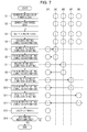
- Fig. 7 is a flowchart illustrating a communication procedure that allows handshaking communication to be made in information communication for timing control; while Fig. 8 is a flowchart illustrating a communication procedure that does not allow any handshaking communication to be made in the information communication for timing control.
- information (command data and control information based thereon) involved in each of three kinds of data or information that is, the block of printing unit data, the piece of data setting completion information transmitted from each of the sub-PCs 30C to 30K, and the notification, which is transmitted upon completion of the receptions of the pieces of data setting completion information, makes it possible to make the driving control by the driving controller 34R on the printing sections 10C to 10Lk and the printing medium movement section 20 more suitable.
- Examples of a command indicated by such an involved piece of command data include, but are not limited to, a command for instructing the execution of flushing for eliminating the clogging of target nozzles, and a command for instructing the execution of a nozzle analysis (i.e., an analysis of a signal for detecting the discharging status of a target ink).
- the timing of the execution of each of these operations on each of the inks can be made suitable in accordance with the characteristic and/or the discharge frequency of the relevant ink.
- This suitable timing of the execution of each of the operations can be realized, for each of the inks, by, upon completion of generating a block of printing unit data at a suitable timing point for the execution of the relevant operation, involving a command for instructing the execute of the relevant operation into the generated block of printing unit data.
- the relevant sub-PC 30 involves the command into a piece of data setting completion information, and then transmits the piece of data setting completion, involving the command, to the driving control PC 30R.
- the timing synchronization section 34T consolidates pieces of command data included in collected pieces of data setting completion data, and then notifies the consolidated command data to the driving controller 34R.
- the driving controller 34R drive controls, in accordance with this notification, each of corresponding one or more of the printing sections 10C to 10Lk and the printing medium movement section 20 to allow, for example, a required flushing operation and/or a required nozzle analysis operation to be executed.
- the printing apparatus and the printing method according to this embodiment bring about the following advantageous effects.
- the driving control PC 30R serving as the "driving controller” in the invention, performs timing control on the timings of the settings (transmissions) of the blocks of printing unit data to the respective printing sections 10C to 10Lk and on the timings of the driving controls by the driving control PC 30R on the printing sections 10C to 10Lk and the printing medium movement section 20.
- This timing control is performed through information communication provided by the communication bus 60.
- each of the sub-PCs 30C to 30K is configured to, upon completion of settings (transmissions) of blocks of printing unit data each associated with a corresponding one of colors allocated to the relevant sub-PC 30 into printing sections each included in the printing sections 10C to 10Lk and associated with the corresponding one of the colors, allocated to the relevant sub-PC 30, transmit a piece of data setting completion information to the driving control PC 30R, serving as the "driving controller" in the invention, via the communication bus 60.
- the driving control PC 30R controls the printing sections 10C to 10Lk and the printing medium movement section 20 on the basis of the received pieces of data setting completion information. That is, according to this embodiment, in the information communication through which this timing control is performed, any handshaking communication operation is not performed between the driving control PC 30R and each of the sub-PCs 30C to 30K. Thus, periods of time spent in inquiry operations and waiting operations for waiting for replies thereto in the handshaking communication operations are reduced and, as a result, the reduction of the efficiency of printing processing is eliminated.
- the TCP/IP is employed as a communication protocol for communication made via the communication bus 60. Since the TCP/IP is a high-versatility communication protocol, the employment of the TCP/IP enables realization of constituting a printing apparatus more suitably, and thus, facilitates the change of the installation locations of the driving control PC 30R and the sub-PCs 30C to 30K, and the customization of the printing-data processing ability in accordance with a required printing speed by means of additionally installing one or more sub-PCs.
- the number of colors allocated to distributed color processes by each of the sub-PCs 30C to 30K is two
- the number of allocated colors is not limited to this number, two.
- a configuration that allows each of sub-PCs 30x to be coupled to a corresponding one (or three or more) of printing sections 10x, and allows the each of sub-PCs 30x to execute single-color (or triple- or more color) processing may be employed.
Landscapes
- Engineering & Computer Science (AREA)
- Multimedia (AREA)
- Signal Processing (AREA)
- General Engineering & Computer Science (AREA)
- Physics & Mathematics (AREA)
- General Physics & Mathematics (AREA)
- Theoretical Computer Science (AREA)
- Ink Jet (AREA)
- Record Information Processing For Printing (AREA)
- Accessory Devices And Overall Control Thereof (AREA)
Abstract
Description
- The present invention relates to a printing apparatus and a printing method.
- With the progress of innovation of printing technologies in addition to image processing technologies, ink jet printers serving as printing apparatuses have achieved various printing forms through the use of various representation means for making representations on various printing media. As a result, such an ink jet printer has been extensively used in commercial-use, mid-size printers supporting the production of articles, such as posters, signboards, promotion goods, wrapping paper, and clothing articles, and in industrial-use, large-size printers built in production lines for products. With this trend, technologies that enable realization of not only higher-quality printing but also higher-speed printing for the purpose of the increase of productivity have been required.
- In response to such a requirement, an image recording apparatus (printing apparatus) is disclosed in
JP-A-7-327117 - In such an image recording apparatus, disclosed in
JP-A-7-327117 - An advantage of some aspects of the invention is that a printing apparatus and a printing method are provided that further reduce a period of time required to perform processing on printing data to realize higher-speed printing. These printing apparatus and printing method are realized as described in the following application examples and an embodiment described below.
- According to application example 1, a printing apparatus includes a plurality of printing sections each associated with a corresponding one of printing colors of inks used in the printing apparatus and configured to discharge a corresponding one of the inks onto a printing medium to execute a printing process; a printing medium movement section configured to move the printing medium relatively to the printing sections; a driving controller configured to drive control the printing sections and the printing medium movement section; a plurality of printing data controllers configured to, for each of the printing colors, generate a single-color printing data on a basis of a set of full-color printing data associated with an image, a target of printing, and set a set of printing unit data resulting from dividing the set of single-color printing data, into a corresponding one of the printing sections; and a communication bus forming a bus-shaped network and coupled to the driving controller and the printing data controllers to provide information communication using no handshaking communication. Further, in order to combine the printing process, executed by the each printing section using the set of printing unit data, to perform the printing of the image, the driving controller performs timing control, through the information communication, provided by the communication bus, on the setting of, for the each printing color, the set of printing unit data into the corresponding one of the printing sections, and on the driving control of, by the driving controller, the printing sections and the printing medium movement section.
- In this application example, in order to combine the printing process, executed by the each printing section using the set of printing unit data, to perform the printing of the image, the driving controller performs timing control on the setting of, for the each printing color, the set of printing unit data into the corresponding one of the printing sections, and on the driving control of, by the driving controller, the printing sections and the printing medium movement section. This timing control is performed through the information communication, provided by the communication bus. According to this application example, in the information communication, through which the timing control is performed, no handshaking communication is performed between the driving controller and the printing data controllers. For this reason, the reduction of the efficiency of printing processing due to the handshaking communication (for example, due to periods of time for waiting for replies) is eliminated. Further, in the case where the handshaking communication is performed to perform the timing control between the driving controller and the printing sections, the handshaking communication is performed between the driving controller and the plurality of printing sections, that is, between one point between multi-points, and thus, the number of processes for the handshaking communication is linearly increased. According to this application example, since the handshaking communication is not performed, even when the number of the kinds of used inks is increased, the occurrence of a situation in which, with this increase, a processing time is linearly increased is eliminated.
- According to application example 2, a printing apparatus includes a plurality of printing sections each associated with a corresponding one of printing colors of inks used in the printing apparatus and configured to discharge a corresponding one of the inks onto a printing medium to execute a printing process; a printing medium movement section configured to move the printing medium relatively to the printing sections; a driving controller configured to drive control the printing sections and the printing medium movement section; a plurality of printing data controllers configured to, for each of the printing colors, generate a single-color printing data on a basis of a set of full-color printing data associated with an image, a target of printing, and set a set of printing unit data resulting from dividing the set of single-color printing data, into a corresponding one of the printing sections; and a communication bus forming a bus-shaped network and coupled to the driving controller and the printing data controllers to provide information communication. Further, in order to combine the printing process, executed by the each printing section using the set of printing unit data, to perform the printing of the image, a pair of two sequential processes is repeatedly performed, a prior one of the two sequential processes being a process in which, upon completion of the setting of, for the each printing color, the set of printing unit data into the corresponding one of the printing sections, the printing data controllers transmit a piece of data setting completion information to the driving controller via the communication bus, a subsequent one of the two sequential processes being a process in which, upon receipt of the piece of data setting completion information for each of all of the printing colors from all of the printing data controllers, coupled to the communication bus, the driving controller drive controls the printing sections and the printing medium movement section on a basis of the received piece of data setting completion for the each of all of the printing colors.
- In this application example, in order to combine the printing process, executed by the each printing section using the set of printing unit data, to perform the printing of the image, the driving controller performs timing control on the setting of, for the each printing color, the set of printing unit data into the corresponding one of the printing sections, and on the driving control of, by the driving controller, the printing sections and the printing medium movement section. This timing control is performed through the information communication, provided by the communication bus. According to this application example, upon completion of the setting of, for the each printing color, the set of printing unit data into the corresponding one of the printing sections, the printing data controllers transmit a piece of data setting completion information to the driving controller via the communication bus, and upon receipt of the piece of data setting completion information for each of all of the printing colors from all of the printing data controllers, coupled to the communication bus, the driving controller drive controls the printing sections and the printing medium movement section on the basis of the received piece of data setting completion for the each of all of the printing colors. In this way, when the timing control is performed, the handshaking communication, that is, inquiries from the driving control to the individual printing controllers and replies to the inquiries, is not made. For this reason, the reduction of the efficiency of printing processing due to the handshaking communication (for example, due to periods of time for waiting for replies) is eliminated. Further, in the case where the handshaking communication is performed to perform the timing control between the driving controller and the printing sections, the handshaking communication is performed between the driving controller and the plurality of printing sections, that is, between one point and multi-points, and thus, the number of processes for the handshaking communication is linearly increased. According to this application example, since the handshaking communication is not performed, even when the number of the kinds of used inks is increased, the occurrence of a situation in which, with this increase, a processing time is linearly increased is eliminated.
- In the printing apparatus according to each of the above application examples, a transmission control/Internet protocol (TCP/IP) is employed as a communication protocol for the information communication provided by the communication bus.
- Since the TCP/IP is a high-versatility communication protocol, the employment of the TCP/IP enables realization of constituting a printing apparatus more suitably.
- According to application example 4, a printing method for a printing apparatus includes executing, by each of printing sections each associated with a corresponding one of printing colors of inks used in the printing apparatus, a printing process by discharging a corresponding one of the inks onto a printing medium; moving, by a printing medium movement section, the printing medium relatively to the printing sections; driving control, by a driving controller, the printing sections and the printing medium movement section; for each of the printing colors, generating, by printing data controllers, a single-color printing data on a basis of a set of full-color printing data associated with an image, a target of printing, and setting, by the printing data controllers, a set of printing unit data resulting from dividing the set of single-color printing data, into a corresponding one of the printing sections; and performing information communication between the driving controller and the printing data controllers using no handshaking communication, via a communication bus forming a bus-shaped network and coupled to the driving controller and the printing data controllers. Further, in order to combine the printing process, executed by the each printing section using the set of printing unit data, to perform the printing of the image, timing control is performed through the information communication, via the communication bus, on the setting of, for the each printing color, the set of printing unit data into the corresponding one of the printing sections, and on the driving control of, by the driving controller, the printing sections and the printing medium movement section.
- In this application example, in order to combine the printing process, executed by the each printing section using the set of printing unit data, to perform the printing of the image, the driving controller performs timing control on the setting of, for the each printing color, the set of printing unit data into the corresponding one of the printing sections, and on the driving control of, by the driving controller, the printing sections and the printing medium movement section. This timing control is performed through the information communication, via the communication bus. According to this application example, in the information communication, through which the timing control is performed, no handshaking communication is performed between the driving controller and the printing data controllers. For this reason, the reduction of the efficiency of printing processing due to the handshaking communication (for example, due to periods of time for waiting for replies) is eliminated. Further, in the case where the handshaking communication is performed to perform the timing control between the driving controller and the printing sections, the handshaking communication is performed between the driving controller and the plurality of printing sections, that is, between one point between multi-points, and thus, the number of processes for the handshaking communication is linearly increased. According to this application example, since the handshaking communication is not performed, even when the number of the kinds of used inks is increased, the occurrence of a situation in which, with this increase, a processing time is linearly increased is eliminated.
- According to application example 5,
a printing method for a printing apparatus includes executing, by each of printing sections each associated with a corresponding one of printing colors of inks used in the printing apparatus, a printing process by discharging a corresponding one of the inks onto a printing medium; moving, by a printing medium movement section, the printing medium relatively to the printing sections; driving control, by a driving controller, the printing sections and the printing medium movement section; for each of the printing colors, generating, by printing data controllers, a single-color printing data on a basis of a set of full-color printing data associated with an image, a target of printing, and setting, by the printing data controllers, a set of printing unit data resulting from dividing the set of single-color printing data, into a corresponding one of the printing sections; and performing information communication between the driving controller and the printing data controllers, via a communication bus forming a bus-shaped network and coupled to the driving controller and the printing data controllers. Further, in order to combine the printing process, executed by the each printing section using the set of printing unit data, to perform the printing of the image, a pair of two sequential processes is repeatedly performed, a prior one of the two sequential processes being a process in which, upon completion of the setting of, for the each printing color, the set of printing unit data into the corresponding one of the printing sections, a piece of data setting completion information is transmitted by the printing data controllers to the driving controller via the communication bus, a subsequent one of the two sequential processes being a process in which, upon receipt of the piece of data setting completion information for each of all of the printing colors from all of the printing data controllers, coupled to the communication bus, driving control of the printing sections and the printing medium movement section is performed by the driving controller on a basis of the received piece of data setting completion for the each of all of the printing colors. - In this application example, in order to combine the printing process, executed by the each printing section using the set of printing unit data, to perform the printing of the image, the driving controller performs timing control on the setting of, for the each printing color, the set of printing unit data into the corresponding one of the printing sections, and on the driving control of, by the driving controller, the printing sections and the printing medium movement section. This timing control is performed through the information communication, via the communication bus. According to this application example, upon completion of the setting of, for the each printing color, the set of printing unit data into the corresponding one of the printing sections, the printing data controllers transmit a piece of data setting completion information to the driving controller via the communication bus, and upon receipt of the piece of data setting completion information for each of all of the printing colors from all of the printing data controllers, coupled to the communication bus, the driving controller drive controls the printing sections and the printing medium movement section on the basis of the received piece of data setting completion for the each of all of the printing colors. In this way, when the timing control is performed, the handshaking communication, that is, inquiries from the driving control to the individual printing controllers and replies to the inquiries, is not made. For this reason, the reduction of the efficiency of printing processing due to the handshaking communication (for example, due to periods of time for waiting for replies) is eliminated. Further, in the case where the handshaking communication is performed to perform the timing control between the driving controller and the printing sections, the handshaking communication is performed between the driving controller and the plurality of printing sections, that is, between one point between multi-points, and thus, the number of processes for the handshaking communication is linearly increased. According to this application example, since the handshaking communication is not performed, even when the number of the kinds of used inks is increased, the occurrence of a situation in which, with this increase, a processing time is linearly increased is eliminated.
- Embodiments of the invention will now be described by way of example only with reference to the accompanying drawings, wherein like numbers reference like elements.
-
Fig. 1 is a front view of a printing system in a conventional technology illustrating the configuration of the printing system including a printing apparatus. -
Fig. 2 is a block diagram illustrating the configuration of a printing system including a printing apparatus in a conventional technology. -
Fig. 3 is a diagram illustrating processes performed by a printer driver. -
Fig. 4 is a plan view of a printing head illustrating the configuration of the printing head. -
Fig. 5 is a front view of a printing system according toembodiment 1 illustrating the configuration of the printing system including a printing apparatus. -
Fig. 6 is a block diagram of a printing system including a printing apparatus according toembodiment 1. -
Fig. 7 is a flowchart illustrating a communication procedure that allows handshaking communication to be performed in information communication for timing control. -
Fig. 8 is a flowchart illustrating a communication procedure that does not allow any handshaking communication to be performed in information communication for timing control. - Before describing an embodiment obtained by embodying the invention, first, an example based on a conventional technology will be described below with reference to some of the drawings. In addition, in the following figures, in order to make it easier to understand the illustration, drawing scales may be different from actual scales. Further, with respect to coordinates appended in some of the following figures, a Z-axis direction corresponds to an upward and downward direction; a +Z direction corresponds to an upward direction; a Y-axis direction corresponds to a frontward and backward direction; a +Y direction corresponds to a frontward direction; an X-axis direction corresponds to a leftward and rightward direction; a +X direction corresponds to a leftward direction; and an X-Y plane corresponds to a horizontal plane.
-
Fig. 1 is a front view of aprinting system 9, a printing system in a conventional technology, illustrating the configuration of theprinting system 9 including aprinting apparatus 109.Fig. 2 is a block diagram of theprinting system 9. - The
printing system 9 includes theprinting apparatus 109 and a personal computer 110 (hereinafter referred to as a PC 110). Thepersonal computer 110 is coupled with theprinting apparatus 109. Theprinting apparatus 109 is an ink jet printer configured to execute printing of a desired printing image (hereinafter also referred to as just an image) on aprinting medium 5, having a long size and supplied in a wound, roll-shaped state, on the basis of printing data received from thePC 110. - The
PC 110 includes aprinter controller 111, aninput section 112, adisplay section 113, astorage section 114, and any other section, and controls a print job in accordance with which theprinting apparatus 109 executes printing. - The
printer controller 111 includes a CPU (arithmetic operation unit) and storage media, such as RAM and ROM, (these components being omitted from illustration), and performs concentrated management of theentire printing system 9. - The
input section 112 corresponds to information input means serving as human interfaces, and specifically corresponds to ports to which information input devices, such as a keyboard, are coupled. - The
display section 113 corresponds to an information display means (display) serving as a human interface, and displays thereon information input from theinput section 112, images to be printed by theprinting apparatus 109, information in relation to a print job, and any other kind of information. - The
storage section 114 corresponds to rewritable storage media, such as a hard disc drive (HDD) and a memory card, and stores therein software executed by the PC 110 (i.e., programs executed by the printer controller 111), images to be printed, information in relation to a print job, and any other information. - The software executed by the
PC 110 includes general image processing application software (hereinafter referred to as an application) and printer driver software (hereinafter referred to as a printer driver). - The
printing apparatus 109 includes aprinting section 10, a printingmedium movement section 20, acontroller 30, and any other section. Upon receipt of printing data from thePC 110, theprinting apparatus 109 allows thecontroller 30 to control the printingmedium movement section 20 to execute printing of an image (forming of an image) onto theprinting medium 5. - The printing data is data for use in forming an image, and is data having been subjected to processing for converting general RGB digital image information obtained through, for example, a digital camera into data printable by the application and the printer driver, which are installed in the
PC 110. The printing data includes commands for controlling theprinting apparatus 109. - The
printing section 10 includes aprinting head 11, aprinting head controller 12, and any other component. - The printing
medium movement section 20 includes a main-scanningsection 40, asub-scanning section 50 and any other section. The main-scanningsection 40 includes a carriage 41, a guide shaft 42, a carriage motor (omitted from illustration), and any other component. Thesub-scanning section 50 includes a feed section 51, acontainer section 52,transport rollers 53, aplaten 55, and any other component. - The
printing head 11 includes a plurality of nozzles (nozzle rows) through which printing inks (hereinafter referred to as inks) are ejected in the form of liquid droplets (hereinafter also referred to as ink droplets). Theprinting head 11 is mounted in the carriage 41 and reciprocates in a scanning direction (the Y-axis direction shown inFig. 1 ) with the carriage 41, which moves in the scanning direction. While moving in the scanning direction, theprinting head 11 ejects ink droplets onto theprinting medium 5, supported by theplaten 55, under the control of thecontroller 30, and as a result, dot rows (raster lines) along the scanning direction are formed on theprinting medium 5. - Non-limiting examples of the inks include, as an ink set of high-density ink compositions, an ink set of four color inks obtained by adding a black (K) ink to an ink set of three color inks consisting of a cyan (C) ink, a magenta (M) ink, and a yellow (Y) ink, and also include, as an ink set consisting of high-density ink compositions and low-density ink compositions each obtained by reducing a corresponding one of the high-density ink compositions, an ink set of eight color inks consisting of, in addition to the above four colors, a light-cyan (Lc) ink, a light-magenta (Lm) ink, a light-yellow (Ly) ink, and a light-black (Lk) ink.
- In this embodiment, a piezo method is employed as a preferred example of a method for ejecting ink droplets (i.e., an ink jet method). This piezo method is a method that allows a piezoelectric element (a piezo element) to apply a pressure in accordance with a printing information signal to an ink stored in a pressure chamber to allow an ink droplet to be ejected (discharged) through a nozzle communicating with the pressure chamber so as to execute a printing operation.
- In addition, the method of discharging ink droplets is not limited to this method but may be a different method that allows liquid-drop shaped inks to be ejected onto a printing medium to allow dot clusters to be formed on the printing medium. Examples of such a different method include, but are not limited to, a method that allows a small pump to apply a pressure to an ink and allows a liquid crystal vibrator or any other vibrator to mechanically vibrate a nozzle so as to cause an ink droplet to be ejected through the nozzle, and a method that, in accordance with a recording information signal, allows a minute electrode to heat an ink to cause a bubble to be formed in the ink to cause an ink droplet to be ejected so as to allow a recording operation to be executed (this method being called a thermal jet method).
- The printing medium movement section 20 (including the main-scanning
section 40 and the sub-scanning section 50) allows theprinting medium 5 to move relatively to theprinting section 10 under the control of thecontroller 30. - The guide shaft 42 extends in the scanning direction and supports the carriage 41 in a state in which the carriage 41 is slidably in contact with the guide shaft 42. The carriage motor is a drive source for allowing the carriage 41 to reciprocate along the guide shaft 42. That is, the main-scanning section 40 (including the carriage 41, the guide shaft 42, and the carriage motor) allows the carriage 41 (i.e., the printing head 11) to move in the scanning direction, along the guide shaft 42, under the control of the
controller 30. - The feed section 51 supports a reel around which the
printing medium 5 is wound in a roll shape, in a way that allows the reel to freely rotate, and feeds out theprinting medium 5 to a transport path. Thecontainer section 52 supports a reel for winding theprinting medium 5, in a way that allows the reel to freely rotate, and winds up therecording medium 5, having been subjected to printing, from the transport path. - The
transport rollers 53 include a drive roller configured to move theprinting medium 5 in a sub-scanning direction (i.e., the X-axis direction shown inFig. 1 ) intersecting with the main-scanning direction, a driven roller configured to rotate in conjunction with the movement of theprinting medium 5, and any other component. Further, thetransport rollers 53 form a transport path along which theprinting medium 5 is transported from the feed section 51 to thecontainer section 52 via a printing region of theprinting section 10. This printing region is a region which is located on the upper surface of theplaten 55 and above which theprinting head 11 moves during a scanning operation. - The
controller 30 includes aninterface section 31, aCPU 32, amemory 33, a drivingcontroller 34, a printingdata setting section 35, and any other section, and controls theprinting apparatus 109. - The
interface section 31 performs data transmission/reception between thePC 110 and theprinting apparatus 109. - The
CPU 32 is an arithmetic processing device for controlling theentire printing apparatus 109. - The
memory 33 is a storage medium that retains an area for storing therein programs executed by theCPU 32, a work area for use in the execution of the programs, and any other area, and is constituted by memory elements, such as RAM and EEPROM. - The
CPU 32 is configured to, via the drivingcontroller 34, control the printing medium movement section 20 (the main-scanningsection 40 and the sub-scanning section 50) and the printing portion 10 (the printing head 11) in accordance with the programs stored in thememory 33 and printing data received from thePC 110 and stored in thememory 33, and further, theCPU 32 is configured to, via the printingdata setting section 35, sequentially transmit raster data described below to theprinting head controller 12 on the basis of the printing data stored in thememory 33. - Printing onto the
printing medium 5 is started upon transmission of a set of printing data from thePC 110 coupled to theprinting apparatus 109. The set of printing data is generated by the printer driver. Hereinafter, processes by the printer driver will be described referring toFig. 3. Fig. 3 is a diagram illustrating processes performed by the printer driver. - Upon receipt of a set of image data, such as a set of text data or a set of full-color image data, from an application, the printer driver converts the set of image data into a set of printing data having a format interpretable by the
printing apparatus 109, and outputs the set of printing data to theprinting apparatus 109. When converting the set of image data from the application into the set of printing data, the printing driver performs resolution conversion processing, color conversion processing, halftone processing, rasterization processing, command addition processing, and any other processing. - The resolution conversion processing is processing for converting the resolution of the set of image data output from the application into a resolution (a printing resolution) at which printing is to be executed onto the
printing medium 5. For example, when a printing resolution of 720 x 720 dpi is specified, the resolution conversion processing converts a set of image data having been received from the application and having a vector format into a set of image data having a bit map format and having a resolution of 720 x 720 dpi. The set of image data after the resolution conversion processing is composed of pieces of pixel data each associated with a corresponding one of pixels arranged in a matrix shape. Each of the pixels has a combination of grayscale levels each being one of, for example, 256 grayscale levels in a corresponding one of RGB-color spaces. That is, each piece of image data constituting the set of image data after the resolution conversion processing indicates a combination of grayscale levels that is associated with a corresponding pixel. - A block of pieces of image data each associated with a corresponding one of pixels forming one row and arranged in a predetermined direction among the pixels arranged in the matrix shape is called a block of raster data. In addition, the predetermined direction, in which the pixels forming one row and associated with a block of raster data are arranged, corresponds to the movement direction (the scanning direction), in which the
printing head 11 moves when an image is printed. - The color conversion processing is processing for converting RGB data into data in spaces of a CMYK-color system. The CMYK color corresponds to cyan (C), magenta (M), yellow (Y), and black (K), and a set of image data in the spaces of the CMYK-color system is a set of data corresponding to the colors of inks included in the
printing apparatus 109. Thus, for example, when theprinting apparatus 109 uses ten kinds of inks in the CMYK-color system, the printer driver generates a set of image data in ten-dimensional spaces of the CMYK-color system. - The color conversion processing is performed on the basis of a table (a color-conversion lookup table LUT) in which each of grayscale levels for RGB data is associated with a corresponding one of grayscale levels for CMYK-color system data. In addition, a piece of image data after the color conversion processing is a piece of CMYK-color system data represented by the spaces of the CMYK-color system and having a combination of grayscale levels each being one of, for example, 256 grayscale levels in a corresponding one of the spaces of the CMYK-color system.
- The halftone processing is processing for converting a set of image data based on a high grayscale level (256 grayscale levels) into a set of data based on a grayscale level that is low enough for the formation by the
printing apparatus 109. Through the halftone processing, each piece of data indicating a combination of grayscale levels each being one of the 256 grayscale levels is converted into a piece of data indicating a combination of grayscale levels each being one of two grayscale levels represented by one bit of data, or a combination of grayscale levels each being one of four grayscale levels represented by two bits of data. A set of image data after the halftone processing is a set of data based on image data represented by one bit or two bits of data, and this set of data becomes a set of pieces of data each indicating a formation of a dot corresponding to each pixel (i.e., indicating the presence or absence of a dot or the size of a dot). - For example, in the case where each piece of image data is composed of two bits (indicating four grayscales), the formation of a corresponding dot is converted into one of four stages: a first one being a stage corresponding to a grayscale level [00] and indicating the formation of no dot; a second one being a stage corresponding to a grayscale level [01] and indicating the formation of a small-size dot; a third one being a stage corresponding to a grayscale level [10] and indicating the formation of a middle-size dot; and a fourth one being a stage corresponding to a grayscale level [11] and indicating the formation of a large-size dot. Subsequently, the printer driver determines a dot generation ratio for each of the dot sizes, and then, generates a set of image data using a dither method or an error diffusion method to allow the
printing apparatus 109 to form dots so as to allow the dots to be dispersed. - The rasterization processing is processing for rearranging pieces of image data arranged in a matrix shape, in accordance with dot formation order in a printing execution. For example when, in a printing execution, some dot formation processes resulting from dividing dot formation processing are performed, sets of image data each associated with a corresponding one of the dot formation processes are extracted, and pieces of image data constituting each of the sets of image data are rearranged in accordance with the dot formation order. In addition, the dot formation order in a printing execution differs depending on the kind of printing method, and thus, the rasterization processing is performed in accordance with the kind of printing method.
- The command addition processing is processing for adding command data to a set of data having been subjected to the rasterization processing. A non-limiting example of the command data includes transportation data specifying a transportation speed of a medium.
- A set of printing data having been generated through the above pieces of processing is transmitted to the
printing apparatus 109 by the printer driver. - Next, one embodiment resulting from embodying the invention will be described. The following is just an embodiment of the invention, and does not limit the invention. In addition, in the following description, the same constituent elements as those of the foregoing example, in the conventional technology, will be denoted by the same reference signs as those in the foregoing example, and duplicated description thereof will be omitted.
- First, the
printing head 11 in this embodiment will be described. -
Fig. 4 is a plan view of theprinting head 11 illustrating the configuration of theprinting head 11. - The
printing head 11 is constituted as an aggregate obtained by binding up eightink discharging heads 13 in the scanning direction (the Y-axis direction). Each of the eightink discharging heads 13 is associated with a corresponding one of the above eight colors, cyan (C), magenta (M), yellow (Y), black (K), light cyan (Lc), light magenta (Lm), light yellow (Ly), and light black (Lk). - Each of the
ink discharging heads 13 includes thirty twonozzle chips 14. The nozzle chips 14 are arranged in a zig-zag shape so as to form two rows extending in the X-axis direction. - Each of the nozzle chips 14 includes two rows each consisting of 400 through-hole shaped nozzles that are formed at intervals of 1/360 inches.
- This configuration enables the
printing head 11 to form 25000 dots colored in each of the eight colors and arranged at pitches of 1/720 inches (i.e., 720 dpi) in the sub-scanning direction (the X-axis direction). - For example when the
printing head 11 performs 20000 ink discharging operations at 720 dpi through each nozzle during one single-direction movement in the scanning direction (hereinafter referred to as one pass), as a result, up to four billion (= 25000 x 8 x 20000) dots per pass are formed. - The
printing apparatus 109 repeats a pass that allows the inks to be discharged in accordance with raster data based on printing data having been generated from image data to form an image corresponding to the image data on theprinting medium 5. - Here, a set of pieces of raster data used for a printing execution for each pass is referred to as a block of printing unit data. When the 20000 ink discharging operations through each nozzle are performed during one pass, a minimum unit of pieces of raster data constituting a block of printing unit data corresponds to four billion (= 25000 x 8 x 20000) dots, and these pieces of raster data are sequentially transmitted from the
controller 30 to a buffer memory included in theprinting head controller 12. In addition, pieces of raster data corresponding to a plurality of passes may be handled as a block of printing unit data depending on the capacity of the buffer memory included in the printing head controller 12 (that is, in the case where the buffer memory included in theprinting head controller 12 has a capacity enough to store such pieces of raster data corresponding to a plurality of passes). - As described above, a huge volume of data is required to be processed in execution of printing, and thus, in the printing apparatus 109 (in the printing method in the conventional technology), depending on the size and the resolution of an image to be printed, a period of time required to generate each block of printing unit data that is associated with dots per one pass, and set the generated each block of printing unit data into the
printing section 10 may be longer than a period of time required to execute printing during one pass (i.e., the sum of a period of time required to allow theprinting head 11 to perform scanning operation during one pass and a period of time required to move theprinting medium 5 in the sub-scanning direction by a predetermined amount). As a result, a period of waiting time between succeeding passes is made longer, and this long period of waiting time may adversely affect the quality of printing and/or may make a period of printing time longer than a desired time. - In contrast, this embodiment is configured such that the processing for generating and setting each block of printing unit data is distributed into a plurality of distributed processes that are concurrently executed, preferably so as not to make a period of time required to set the each block of printing unit data longer than a period of time required to perform the scanning operation by the
printing head 11 during one pass. The period of time required to set the each block of printing unit data is the sum of a period of time required to allow the each block of printing unit data to be distributed to and subjected to the plurality of distributed processes, and a period of time required to perform a process of causing the timing points of the plurality distributed processes to coincide with one another. - Hereinafter, specific description will be made.
-
Fig. 5 is a front view of aprinting system 1, a printing system according toembodiment 1, illustrating the configuration of theprinting system 1 including aprinting apparatus 100.Fig. 6 is a block diagram of theprinting system 1. - The
printing system 1 includes theprinting apparatus 100 and apersonal computer 110. Thepersonal computer 110 is coupled to theprinting apparatus 100. - The
printing apparatus 100 is configured to, in order to reduce a period of time required to generate each block of printing unit data from a set of printing data received from thePC 110 and set the each block of printing unit data into theprinting section 10, included in theprinting apparatus 109, distribute the function of thecontroller 30, included in theprinting apparatus 109, into five personal computers (hereinafter referred to as sub-PCs). - Further, the
printing section 10, which receives the generated block of printing unit data, is divided into a plurality of printing sections each associated with a corresponding one of kinds of used inks to allow the plurality of printing sections to receive the generated blocks of printing unit data independently from one another. The plurality of printing sections include aprinting section 10C, aprinting section 10M, aprinting section 10Y, aprinting section 10K, a printing section 10Lc, a printing section 10Lm, a printing section 10Ly, and a printing section 10Lk, and these printing portions will be also collectively referred to asprinting sections 10C to 10Lk hereinafter. Each of theprinting sections 10C to 10Lk includes anink discharging head 13, from which a corresponding one of color inks is discharged, a corresponding one of a plurality of printing head controllers (omitted from illustration), and any other component. The plurality of printing head controllers include a printing head controller 12C, a printing head controller 12M, a printing head controller 12Y, a printing head controller 12K, a printing head controller 12Lc, a printing head controller 12Lm, a printing head controller 12Ly, and a printing head controller 12Lk, and these printing head controllers will be also collectively referred to as printing head controllers 12C to 12Lk hereinafter. - The five sub-PCs, which perform distributed processes, include a driving
control PC 30R, asub-PC 30C, a sub-PC 30M, a sub-PC 30Y, and asub-PC 30K. - Each of the sub-PCs includes an
interface section 31, aCPU 32, and amemory 33, just like thecontroller 30, and is coupled to thePC 110 via theinterface section 31 and acommunication bus 60, the communication bus forming a bus topology network. For a communication protocol for use in coupling to thecommunication bus 60, a transmission control protocol/Internet protocol (TCP/IP) is employed. - The driving
control PC 30R is a sub-PC serving as a "driving controller" in the invention, and having the same function as that of the drivingcontroller 34, included in theprinting apparatus 109, and includes a drivingcontroller 34R and atiming synchronization section 34T. - The
timing synchronization section 34T has the function of synchronizing the processes, which are distributed to the respective five sub-PCs, and notifying the result of the synchronization to the drivingcontroller 34R. - The driving
controller 34R controls a printing medium movement section 20 (i.e., a main-scanningsection 40 and a sub-scanning section 50) and theprinting sections 10C to 10Lk in accordance with the notification from thetiming synchronization section 34T, the set of printing data received from thePC 110, and any other information. - The
sub-PC 30C, the sub-PC 30M, thesub-PC 30Y, and thesub-PC 30K (these being also collectively referred to as sub-PCs 30C to 30K hereinafter) each correspond to a "printing data controller" in the invention, and respectively include a printingdata setting section 35C, a printingdata setting section 35M, a printingdata setting section 35Y, and a printingdata setting section 35K (these being also collectively referred to as printingdata setting sections 35C to 35K hereinafter). - In the
conventional printing apparatus 109, thecontroller 30 processes the set of printing data, in eight dimensional spaces of the CMYK-color system, each of the eight dimensional spaces being associated with a corresponding one of the eight color inks, and then, sequentially transmits the data set of raster data (i.e., the block of printing unit data) to theprinting head controller 12 via the printingdata setting section 35; while, in theprinting apparatus 100 of the present invention, processing target colors are allocated to each of the sub-PCs 30C to 30K, each serving as a "printing data controller" in the invention. Specifically, thesub-PC 30C executes processes on cyan (C) and light cyan (Lc); the sub-PC 30M executes processes on magenta (M) and light magenta (LM); thesub-PC 30Y executes processes on yellow (Y) and light yellow (Ly); and thesub-PC 30K executes processes on black (K) and light black (Lk). - Further, the
sub-PC 30C, the sub-PC 30M, thesub-PC 30Y, and thesub-PC 30K are respectively coupled to a pair of theprinting section 10C and the printing section 10Lc, a pair of theprinting section 10M and the printing section 10Lm, a pair of theprinting section 10Y and the printing section 10Ly, and a pair of theprinting section 10K and the printing section 10Lk. Moreover, each of the sub-PCs 30C to 30K is coupled to a corresponding one of the pairs of printing sections via a corresponding one of high-speed communication interfaces 70, such as StarFabric interfaces. - Each of the sub-PCs 30C to 30K extracts corresponding sets of allocated-color data from the set of printing data, having been received from the
PC 110 via thecommunication bus 60, and then, performs processing on the extracted sets of allocated-color data. Specifically, each of the sub-PCs 30C to 30K extracts corresponding sets of allocated-color data from the set of printing data to generate sets of single-color printing data each associated with a corresponding one of the allocated colors, and then, generates sets of raster data from the respective sets of single-color printing data to compose blocks of printing unit data. For example, thesub-PC 30C extracts a set of cyan (C) data and a set of light cyan (Lc) data from the set of printing data to generate a block of printing unit data composed of pieces of cyan (C) raster data and a block of printing unit data composed of pieces of light cyan (Lc) raster data, and then sequentially sets (transmits) each of these two kinds of blocks of printing unit data to a corresponding one of theprinting sections 10C and 10Lc via one of the high-speed communication interfaces 70 that is associated with thesub-PC 30C. - In addition, the method of extracting (converting) the set of allocated-color printing data from the set of full-color printing data is not limited to the above method, in which the extraction is performed by each of the sub-PCs 30C to 30K, but, for example, a method in which the extraction is performed by the
PC 110 may be employed. In such a method, a set of printing data transmitted from thePC 110 to each of the sub-PCs 30C to 30K is not a set of full-color printing data, but a set of printing data having been preliminarily converted by thePC 110 so as to allow the converted set of printing data to be associated with colors allocated to the each of the sub-PCs 30C to 30K. - In the case where, as described above, separately generated blocks of printing unit data are each set (transmitted) to a corresponding one of the
printing sections 10C to 10Lk, the timing points of settings of the blocks of printing unit data are required to be synchronized with the timing point of the driving of the printingmedium movement section 20. In this embodiment, this synchronization is made in a manner described below. - When each of the sub-PCs 30C to 30K has completed settings (transmissions) of blocks of allocated-color printing unit data into corresponding ones of the
printing sections 10C to 10Lk, the relevant sub-PC 30 transmits a piece of data setting completion information to the drivingcontrol PC 30R, serving as the "driving controller" in the invention, via thecommunication bus 60. The drivingcontrol PC 30R refers to the pieces of data setting completion information, having been received in the function of thetiming synchronization section 34T. - Each of the pieces of data setting completion information includes information in relation to colors allocated to a corresponding one of the sub-PCs 30C to 30K, the range of a setting completed block of printing unit data (i.e., the range of a setting completed pass), and any other information. One sub-PC 30C to 30K may provide a separate piece of data setting completion information for each color, or a single piece of data setting completion information for both (or a subset or all) the colors it is responsible for. The claims of the present application should be construed accordingly.
- Upon completion of the receptions of the pieces of data setting completion information from all of the sub-PCs 30C to 30K, coupled to the
communication bus 60, that is, substantially upon confirmation of settings of blocks of printing unit data having the same pass range and corresponding to all of the respective colors into theprinting portions 10C to 10Lk, thetiming synchronization section 34T notifies this confirmation result to the drivingcontroller 34R. - The driving
controller 34R drive controls theprinting sections 10C to 10Lk and the printingmedium movement section 20 on the basis of the notification. - In this way, in the information communication, through which the timing control between the driving
control PC 30R and each of the sub-PCs 30C to 30K is performed, any handshaking communication operation is not performed. That is, while a pair of the setting of a block of printing unit data and the driving of the printingmedium movement section 20 is repeated (that is, while printing is executed), any information inquiry from the drivingcontrol PC 30R to each of the sub-PCs 30C to 30K is not made. -
Fig. 7 is a flowchart illustrating a communication procedure that allows handshaking communication to be made in information communication for timing control; whileFig. 8 is a flowchart illustrating a communication procedure that does not allow any handshaking communication to be made in the information communication for timing control. - As clearly understood from the comparison between
Fig. 7 andFig. 8 , since any handshaking communication operation is not performed in this embodiment, periods of time spent in inquiry operations and waiting operations for waiting for replies thereto in the handshaking communication operations are reduced. Further, even when the number of the kinds of used inks is increased and, with this increase, the number of divided processes is increased, a situation in which the number of operations of communication with the divided processes is linearly increased because of increased handshaking communication operations does not occur. - Moreover, information (command data and control information based thereon) involved in each of three kinds of data or information, that is, the block of printing unit data, the piece of data setting completion information transmitted from each of the sub-PCs 30C to 30K, and the notification, which is transmitted upon completion of the receptions of the pieces of data setting completion information, makes it possible to make the driving control by the driving
controller 34R on theprinting sections 10C to 10Lk and the printingmedium movement section 20 more suitable. - Examples of a command indicated by such an involved piece of command data include, but are not limited to, a command for instructing the execution of flushing for eliminating the clogging of target nozzles, and a command for instructing the execution of a nozzle analysis (i.e., an analysis of a signal for detecting the discharging status of a target ink). The timing of the execution of each of these operations on each of the inks can be made suitable in accordance with the characteristic and/or the discharge frequency of the relevant ink. This suitable timing of the execution of each of the operations can be realized, for each of the inks, by, upon completion of generating a block of printing unit data at a suitable timing point for the execution of the relevant operation, involving a command for instructing the execute of the relevant operation into the generated block of printing unit data.
- When one the sub-PCs 30C to 30K has found that such a command is included in a corresponding block of printing unit having been set (transmitted), the
relevant sub-PC 30 involves the command into a piece of data setting completion information, and then transmits the piece of data setting completion, involving the command, to the drivingcontrol PC 30R. Thetiming synchronization section 34T consolidates pieces of command data included in collected pieces of data setting completion data, and then notifies the consolidated command data to the drivingcontroller 34R. The drivingcontroller 34R drive controls, in accordance with this notification, each of corresponding one or more of theprinting sections 10C to 10Lk and the printingmedium movement section 20 to allow, for example, a required flushing operation and/or a required nozzle analysis operation to be executed. - As described above, the printing apparatus and the printing method according to this embodiment bring about the following advantageous effects.
- In this embodiment, in order to combine printing processes using blocks of printing unit data to perform printing of a printing target image, the driving
control PC 30R, serving as the "driving controller" in the invention, performs timing control on the timings of the settings (transmissions) of the blocks of printing unit data to therespective printing sections 10C to 10Lk and on the timings of the driving controls by the drivingcontrol PC 30R on theprinting sections 10C to 10Lk and the printingmedium movement section 20. This timing control is performed through information communication provided by thecommunication bus 60. Specifically, each of the sub-PCs 30C to 30K is configured to, upon completion of settings (transmissions) of blocks of printing unit data each associated with a corresponding one of colors allocated to the relevant sub-PC 30 into printing sections each included in theprinting sections 10C to 10Lk and associated with the corresponding one of the colors, allocated to therelevant sub-PC 30, transmit a piece of data setting completion information to the drivingcontrol PC 30R, serving as the "driving controller" in the invention, via thecommunication bus 60. Upon completion of the receptions of the pieces of setting completion information from all of the sub-PCs 30C to 30K, coupled to thecommunication bus 60, the drivingcontrol PC 30R (thetiming synchronization section 34T) drive controls theprinting sections 10C to 10Lk and the printingmedium movement section 20 on the basis of the received pieces of data setting completion information. That is, according to this embodiment, in the information communication through which this timing control is performed, any handshaking communication operation is not performed between the drivingcontrol PC 30R and each of the sub-PCs 30C to 30K. Thus, periods of time spent in inquiry operations and waiting operations for waiting for replies thereto in the handshaking communication operations are reduced and, as a result, the reduction of the efficiency of printing processing is eliminated. Further, even when the number of the kinds of used inks is increased and, with this increase, the number of divided processes is caused to be increased, a situation in which the number of operations of communication with the divided processes is linearly increased because of increased handshaking communication operations does not occur, and thus, the establishment of a printing system is facilitated to a greater degree. - Further, the TCP/IP is employed as a communication protocol for communication made via the
communication bus 60. Since the TCP/IP is a high-versatility communication protocol, the employment of the TCP/IP enables realization of constituting a printing apparatus more suitably, and thus, facilitates the change of the installation locations of the drivingcontrol PC 30R and the sub-PCs 30C to 30K, and the customization of the printing-data processing ability in accordance with a required printing speed by means of additionally installing one or more sub-PCs. - Although, in this embodiment, the number of colors allocated to distributed color processes by each of the sub-PCs 30C to 30K is two, the number of allocated colors (the number of distributed color processes resulting from dividing color processing) is not limited to this number, two. For example, a configuration that allows each of sub-PCs 30x to be coupled to a corresponding one (or three or more) of printing sections 10x, and allows the each of sub-PCs 30x to execute single-color (or triple- or more color) processing may be employed.
Claims (5)
- A printing apparatus (100) comprising:a plurality of printing sections (10) each associated with a corresponding one of printing colors of inks used in the printing apparatus and configured to discharge a corresponding one of the inks onto a printing medium (5) to execute a printing process;a printing medium movement section (20) configured to move the printing medium relatively to the printing sections;a driving controller (30R) configured to drive control the printing sections and the printing medium movement section;a plurality of printing data controllers (30C-30K) configured to, for each of the printing colors, generate a single-color printing data on a basis of a set of full-color printing data associated with an image, a target of printing, and set a set of printing unit data resulting from dividing the set of single-color printing data, into a corresponding one of the printing sections; anda communication bus (60) coupled to the driving controller and the printing data controllers to provide information communication using no handshaking communication,wherein, in order to combine the printing process, executed by the each printing section using the set of printing unit data, to perform the printing of the image, the driving controller is configured to perform timing control, through the information communication, provided by the communication bus, on the setting of, for the each printing color, the set of printing unit data into the corresponding one of the printing sections, and on the driving control of, by the driving controller, the printing sections and the printing medium movement section.
- A printing apparatus (150) comprising:a plurality of printing sections (10) each associated with a corresponding one of printing colors of inks used in the printing apparatus and configured to discharge a corresponding one of the inks onto a printing medium (5) to execute a printing process;a printing medium movement section (20) configured to move the printing medium relatively to the printing sections;a driving controller (30R) configured to drive control the printing sections and the printing medium movement section;a plurality of printing data controllers (30C-30K) configured to, for each of the printing colors, generate a single-color printing data on a basis of a set of full-color printing data associated with an image, a target of printing, and set a set of printing unit data resulting from dividing the set of single-color printing data, into a corresponding one of the printing sections; anda communication bus (60) coupled to the driving controller and the printing data controllers to provide information communication,wherein, in order to combine the printing process, executed by the each printing section using the set of printing unit data, to perform the printing of the image, a pair of two sequential processes is repeatedly performed, a prior one of the two sequential processes being a process in which, upon completion of the setting of, for the each printing color, the set of printing unit data into the corresponding one of the printing sections, the printing data controllers transmit a piece of data setting completion information to the driving controller via the communication bus, a subsequent one of the two sequential processes being a process in which, upon receipt of the piece of data setting completion information for each of all of the printing colors from all of the printing data controllers, coupled to the communication bus, the driving controller drive controls the printing sections and the printing medium movement section on a basis of the received piece of data setting completion for the each of all of the printing colors.
- The printing apparatus according to claim 1 or claim 2, wherein a transmission control/Internet protocol (TCP/IP) is employed as a communication protocol for the information communication provided by the communication bus.
- A printing method for a printing apparatus (100), comprising:executing, by each of printing sections (10) each associated with a corresponding one of printing colors of inks used in the printing apparatus, a printing process by discharging a corresponding one of the inks onto a printing medium (5);moving, by a printing medium movement section (20), the printing medium relatively to the printing sections;driving control, by a driving controller (30R), the printing sections and the printing medium movement section;for each of the printing colors, generating, by printing data controllers (30C-30K), a single-color printing data on a basis of a set of full-color printing data associated with an image, a target of printing, and setting, by the printing data controllers, a set of printing unit data resulting from dividing the set of single-color printing data, into a corresponding one of the printing sections; andperforming information communication between the driving controller and the printing data controllers using no handshaking communication, via a communication bus coupled to the driving controller and the printing data controllers,wherein, in order to combine the printing process, executed by the each printing section using the set of printing unit data, to perform the printing of the image, timing control is performed through the information communication, via the communication bus, on the setting of, for the each printing color, the set of printing unit data into the corresponding one of the printing sections, and on the driving control of, by the driving controller, the printing sections and the printing medium movement section.
- A printing method for a printing apparatus (100), comprising:executing, by each of printing sections (10) each associated with a corresponding one of printing colors of inks used in the printing apparatus, a printing process by discharging a corresponding one of the inks onto a printing medium (5);moving, by a printing medium movement section (20), the printing medium relatively to the printing sections;driving control, by a driving controller (30R), the printing sections and the printing medium movement section;for each of the printing colors, generating, by printing data controllers (30C-30K), a single-color printing data on a basis of a set of full-color printing data associated with an image, a target of printing, and setting, by the printing data controllers, a set of printing unit data resulting from dividing the set of single-color printing data, into a corresponding one of the printing sections; andperforming information communication between the driving controller and the printing data controllers, via a communication bus coupled to the driving controller and the printing data controllers,wherein, in order to combine the printing process, executed by the each printing section using the set of printing unit data, to perform the printing of the image, a pair of two sequential processes is repeatedly performed, a prior one of the two sequential processes being a process in which, upon completion of the setting of, for the each printing color, the set of printing unit data into the corresponding one of the printing sections, a piece of data setting completion information is transmitted by the printing data controllers to the driving controller via the communication bus, a subsequent one of the two sequential processes being a process in which, upon receipt of the piece of data setting completion information for each of all of the printing colors from all of the printing data controllers, coupled to the communication bus, driving control of the printing sections and the printing medium movement section is performed by the driving controller on a basis of the received piece of data setting completion for the each of all of the printing colors.
Applications Claiming Priority (1)
| Application Number | Priority Date | Filing Date | Title |
|---|---|---|---|
| JP2015138474A JP6589421B2 (en) | 2015-07-10 | 2015-07-10 | Printing apparatus and printing method |
Publications (2)
| Publication Number | Publication Date |
|---|---|
| EP3115936A1 true EP3115936A1 (en) | 2017-01-11 |
| EP3115936B1 EP3115936B1 (en) | 2019-02-27 |
Family
ID=56360297
Family Applications (1)
| Application Number | Title | Priority Date | Filing Date |
|---|---|---|---|
| EP16178100.0A Not-in-force EP3115936B1 (en) | 2015-07-10 | 2016-07-06 | Printing apparatus and printing method |
Country Status (2)
| Country | Link |
|---|---|
| EP (1) | EP3115936B1 (en) |
| JP (1) | JP6589421B2 (en) |
Families Citing this family (1)
| Publication number | Priority date | Publication date | Assignee | Title |
|---|---|---|---|---|
| JP7449134B2 (en) * | 2020-03-23 | 2024-03-13 | 株式会社Screenホールディングス | Printing method and printing device |
Citations (4)
| Publication number | Priority date | Publication date | Assignee | Title |
|---|---|---|---|---|
| JPH07327117A (en) | 1994-05-31 | 1995-12-12 | Canon Inc | Image recording apparatus and control method thereof |
| EP1167022A1 (en) * | 1999-12-13 | 2002-01-02 | Dainippon Screen Mfg. Co., Ltd. | Printing system, server controller, and unit controller |
| US20030137698A1 (en) * | 2002-01-18 | 2003-07-24 | Pritchard Thomas B. | System for improving the speed of data processing |
| EP2720136A1 (en) * | 2011-12-30 | 2014-04-16 | Peking University Founder Group Co., Ltd | Distributed digital inkjet printing method and system supporting variable data |
Family Cites Families (4)
| Publication number | Priority date | Publication date | Assignee | Title |
|---|---|---|---|---|
| US20060268316A1 (en) * | 2005-05-24 | 2006-11-30 | Condon John B | Systems and methods for fast color processing |
| JP2007221604A (en) * | 2006-02-17 | 2007-08-30 | Canon Inc | Image forming apparatus |
| JP2013166361A (en) * | 2012-02-17 | 2013-08-29 | Seiko Epson Corp | Printing apparatus |
| JP6015302B2 (en) * | 2012-09-27 | 2016-10-26 | ブラザー工業株式会社 | Printing device |
-
2015
- 2015-07-10 JP JP2015138474A patent/JP6589421B2/en active Active
-
2016
- 2016-07-06 EP EP16178100.0A patent/EP3115936B1/en not_active Not-in-force
Patent Citations (4)
| Publication number | Priority date | Publication date | Assignee | Title |
|---|---|---|---|---|
| JPH07327117A (en) | 1994-05-31 | 1995-12-12 | Canon Inc | Image recording apparatus and control method thereof |
| EP1167022A1 (en) * | 1999-12-13 | 2002-01-02 | Dainippon Screen Mfg. Co., Ltd. | Printing system, server controller, and unit controller |
| US20030137698A1 (en) * | 2002-01-18 | 2003-07-24 | Pritchard Thomas B. | System for improving the speed of data processing |
| EP2720136A1 (en) * | 2011-12-30 | 2014-04-16 | Peking University Founder Group Co., Ltd | Distributed digital inkjet printing method and system supporting variable data |
Also Published As
| Publication number | Publication date |
|---|---|
| EP3115936B1 (en) | 2019-02-27 |
| JP6589421B2 (en) | 2019-10-16 |
| JP2017019179A (en) | 2017-01-26 |
Similar Documents
| Publication | Publication Date | Title |
|---|---|---|
| JP5849395B2 (en) | Recording method and recording apparatus | |
| JP2020040334A (en) | Image processing device, image processing method and program | |
| EP3355245B1 (en) | Image processing method, printing method, image processor, and printing apparatus | |
| EP3392046B1 (en) | Printing apparatus and printing method | |
| JP2009023121A (en) | Liquid ejecting apparatus and method for controlling liquid ejecting apparatus | |
| EP2479711B1 (en) | Recording method and recording apparatus | |
| US11102377B2 (en) | Recording device for recording recording image by nozzle set reciprocating relative to recording medium, image processing device for generating recording data for recording recording image by nozzle set reciprocating relative to recording medium and recording method for recording recording image by nozzle set reciprocating relative to recording medium | |
| JP2016147421A (en) | Printing control device and printing control method | |
| US10491759B2 (en) | Image processing device, printing apparatus, image processing method, and non-transitory computer readable medium | |
| EP3115936B1 (en) | Printing apparatus and printing method | |
| JP2018036984A (en) | Image processing device, printer, image processing method, and program | |
| JP2022038103A (en) | Printer and printing method | |
| US10110778B2 (en) | Image processing method, image processing apparatus, image processing program, and printing system | |
| JP2017148943A (en) | Print control apparatus, print control method, and computer program therefor | |
| JP2018120579A (en) | Image processing method, printing method, image processing device, and printer | |
| JP4661309B2 (en) | Inkjet recording apparatus, control program for inkjet recording apparatus, control method for inkjet recording apparatus, control apparatus for controlling inkjet recording apparatus, control program for control apparatus for controlling inkjet recording apparatus, and control method for control apparatus for controlling inkjet recording apparatus | |
| JP2017078933A (en) | Image processing method, image processing apparatus, and printing system | |
| JP2009023122A (en) | Liquid ejecting apparatus and method for controlling liquid ejecting apparatus | |
| JP2021066027A (en) | Printing apparatus | |
| JP2016147428A (en) | Image processor and image processing method | |
| JP2013212658A (en) | Printing device and printing method | |
| JP2013212635A (en) | Printing device and printing method |
Legal Events
| Date | Code | Title | Description |
|---|---|---|---|
| PUAI | Public reference made under article 153(3) epc to a published international application that has entered the european phase |
Free format text: ORIGINAL CODE: 0009012 |
|
| STAA | Information on the status of an ep patent application or granted ep patent |
Free format text: STATUS: THE APPLICATION HAS BEEN PUBLISHED |
|
| AK | Designated contracting states |
Kind code of ref document: A1 Designated state(s): AL AT BE BG CH CY CZ DE DK EE ES FI FR GB GR HR HU IE IS IT LI LT LU LV MC MK MT NL NO PL PT RO RS SE SI SK SM TR |
|
| AX | Request for extension of the european patent |
Extension state: BA ME |
|
| STAA | Information on the status of an ep patent application or granted ep patent |
Free format text: STATUS: REQUEST FOR EXAMINATION WAS MADE |
|
| 17P | Request for examination filed |
Effective date: 20170711 |
|
| RBV | Designated contracting states (corrected) |
Designated state(s): AL AT BE BG CH CY CZ DE DK EE ES FI FR GB GR HR HU IE IS IT LI LT LU LV MC MK MT NL NO PL PT RO RS SE SI SK SM TR |
|
| GRAP | Despatch of communication of intention to grant a patent |
Free format text: ORIGINAL CODE: EPIDOSNIGR1 |
|
| STAA | Information on the status of an ep patent application or granted ep patent |
Free format text: STATUS: GRANT OF PATENT IS INTENDED |
|
| INTG | Intention to grant announced |
Effective date: 20181002 |
|
| GRAS | Grant fee paid |
Free format text: ORIGINAL CODE: EPIDOSNIGR3 |
|
| GRAA | (expected) grant |
Free format text: ORIGINAL CODE: 0009210 |
|
| STAA | Information on the status of an ep patent application or granted ep patent |
Free format text: STATUS: THE PATENT HAS BEEN GRANTED |
|
| AK | Designated contracting states |
Kind code of ref document: B1 Designated state(s): AL AT BE BG CH CY CZ DE DK EE ES FI FR GB GR HR HU IE IS IT LI LT LU LV MC MK MT NL NO PL PT RO RS SE SI SK SM TR |
|
| REG | Reference to a national code |
Ref country code: GB Ref legal event code: FG4D |
|
| REG | Reference to a national code |
Ref country code: CH Ref legal event code: EP |
|
| REG | Reference to a national code |
Ref country code: AT Ref legal event code: REF Ref document number: 1102440 Country of ref document: AT Kind code of ref document: T Effective date: 20190315 |
|
| REG | Reference to a national code |
Ref country code: IE Ref legal event code: FG4D |
|
| REG | Reference to a national code |
Ref country code: DE Ref legal event code: R096 Ref document number: 602016010263 Country of ref document: DE |
|
| REG | Reference to a national code |
Ref country code: NL Ref legal event code: MP Effective date: 20190227 |
|
| REG | Reference to a national code |
Ref country code: LT Ref legal event code: MG4D |
|
| PG25 | Lapsed in a contracting state [announced via postgrant information from national office to epo] |
Ref country code: FI Free format text: LAPSE BECAUSE OF FAILURE TO SUBMIT A TRANSLATION OF THE DESCRIPTION OR TO PAY THE FEE WITHIN THE PRESCRIBED TIME-LIMIT Effective date: 20190227 Ref country code: NL Free format text: LAPSE BECAUSE OF FAILURE TO SUBMIT A TRANSLATION OF THE DESCRIPTION OR TO PAY THE FEE WITHIN THE PRESCRIBED TIME-LIMIT Effective date: 20190227 Ref country code: SE Free format text: LAPSE BECAUSE OF FAILURE TO SUBMIT A TRANSLATION OF THE DESCRIPTION OR TO PAY THE FEE WITHIN THE PRESCRIBED TIME-LIMIT Effective date: 20190227 Ref country code: LT Free format text: LAPSE BECAUSE OF FAILURE TO SUBMIT A TRANSLATION OF THE DESCRIPTION OR TO PAY THE FEE WITHIN THE PRESCRIBED TIME-LIMIT Effective date: 20190227 Ref country code: NO Free format text: LAPSE BECAUSE OF FAILURE TO SUBMIT A TRANSLATION OF THE DESCRIPTION OR TO PAY THE FEE WITHIN THE PRESCRIBED TIME-LIMIT Effective date: 20190527 Ref country code: PT Free format text: LAPSE BECAUSE OF FAILURE TO SUBMIT A TRANSLATION OF THE DESCRIPTION OR TO PAY THE FEE WITHIN THE PRESCRIBED TIME-LIMIT Effective date: 20190627 |
|
| PG25 | Lapsed in a contracting state [announced via postgrant information from national office to epo] |
Ref country code: RS Free format text: LAPSE BECAUSE OF FAILURE TO SUBMIT A TRANSLATION OF THE DESCRIPTION OR TO PAY THE FEE WITHIN THE PRESCRIBED TIME-LIMIT Effective date: 20190227 Ref country code: HR Free format text: LAPSE BECAUSE OF FAILURE TO SUBMIT A TRANSLATION OF THE DESCRIPTION OR TO PAY THE FEE WITHIN THE PRESCRIBED TIME-LIMIT Effective date: 20190227 Ref country code: LV Free format text: LAPSE BECAUSE OF FAILURE TO SUBMIT A TRANSLATION OF THE DESCRIPTION OR TO PAY THE FEE WITHIN THE PRESCRIBED TIME-LIMIT Effective date: 20190227 Ref country code: GR Free format text: LAPSE BECAUSE OF FAILURE TO SUBMIT A TRANSLATION OF THE DESCRIPTION OR TO PAY THE FEE WITHIN THE PRESCRIBED TIME-LIMIT Effective date: 20190528 Ref country code: IS Free format text: LAPSE BECAUSE OF FAILURE TO SUBMIT A TRANSLATION OF THE DESCRIPTION OR TO PAY THE FEE WITHIN THE PRESCRIBED TIME-LIMIT Effective date: 20190627 Ref country code: BG Free format text: LAPSE BECAUSE OF FAILURE TO SUBMIT A TRANSLATION OF THE DESCRIPTION OR TO PAY THE FEE WITHIN THE PRESCRIBED TIME-LIMIT Effective date: 20190527 |
|
| REG | Reference to a national code |
Ref country code: AT Ref legal event code: MK05 Ref document number: 1102440 Country of ref document: AT Kind code of ref document: T Effective date: 20190227 |
|
| PG25 | Lapsed in a contracting state [announced via postgrant information from national office to epo] |
Ref country code: EE Free format text: LAPSE BECAUSE OF FAILURE TO SUBMIT A TRANSLATION OF THE DESCRIPTION OR TO PAY THE FEE WITHIN THE PRESCRIBED TIME-LIMIT Effective date: 20190227 Ref country code: RO Free format text: LAPSE BECAUSE OF FAILURE TO SUBMIT A TRANSLATION OF THE DESCRIPTION OR TO PAY THE FEE WITHIN THE PRESCRIBED TIME-LIMIT Effective date: 20190227 Ref country code: CZ Free format text: LAPSE BECAUSE OF FAILURE TO SUBMIT A TRANSLATION OF THE DESCRIPTION OR TO PAY THE FEE WITHIN THE PRESCRIBED TIME-LIMIT Effective date: 20190227 Ref country code: ES Free format text: LAPSE BECAUSE OF FAILURE TO SUBMIT A TRANSLATION OF THE DESCRIPTION OR TO PAY THE FEE WITHIN THE PRESCRIBED TIME-LIMIT Effective date: 20190227 Ref country code: SK Free format text: LAPSE BECAUSE OF FAILURE TO SUBMIT A TRANSLATION OF THE DESCRIPTION OR TO PAY THE FEE WITHIN THE PRESCRIBED TIME-LIMIT Effective date: 20190227 Ref country code: DK Free format text: LAPSE BECAUSE OF FAILURE TO SUBMIT A TRANSLATION OF THE DESCRIPTION OR TO PAY THE FEE WITHIN THE PRESCRIBED TIME-LIMIT Effective date: 20190227 Ref country code: AL Free format text: LAPSE BECAUSE OF FAILURE TO SUBMIT A TRANSLATION OF THE DESCRIPTION OR TO PAY THE FEE WITHIN THE PRESCRIBED TIME-LIMIT Effective date: 20190227 |
|
| REG | Reference to a national code |
Ref country code: DE Ref legal event code: R097 Ref document number: 602016010263 Country of ref document: DE |
|
| PG25 | Lapsed in a contracting state [announced via postgrant information from national office to epo] |
Ref country code: PL Free format text: LAPSE BECAUSE OF FAILURE TO SUBMIT A TRANSLATION OF THE DESCRIPTION OR TO PAY THE FEE WITHIN THE PRESCRIBED TIME-LIMIT Effective date: 20190227 Ref country code: SM Free format text: LAPSE BECAUSE OF FAILURE TO SUBMIT A TRANSLATION OF THE DESCRIPTION OR TO PAY THE FEE WITHIN THE PRESCRIBED TIME-LIMIT Effective date: 20190227 |
|
| PG25 | Lapsed in a contracting state [announced via postgrant information from national office to epo] |
Ref country code: AT Free format text: LAPSE BECAUSE OF FAILURE TO SUBMIT A TRANSLATION OF THE DESCRIPTION OR TO PAY THE FEE WITHIN THE PRESCRIBED TIME-LIMIT Effective date: 20190227 |
|
| PLBE | No opposition filed within time limit |
Free format text: ORIGINAL CODE: 0009261 |
|
| STAA | Information on the status of an ep patent application or granted ep patent |
Free format text: STATUS: NO OPPOSITION FILED WITHIN TIME LIMIT |
|
| 26N | No opposition filed |
Effective date: 20191128 |
|
| PG25 | Lapsed in a contracting state [announced via postgrant information from national office to epo] |
Ref country code: SI Free format text: LAPSE BECAUSE OF FAILURE TO SUBMIT A TRANSLATION OF THE DESCRIPTION OR TO PAY THE FEE WITHIN THE PRESCRIBED TIME-LIMIT Effective date: 20190227 Ref country code: MC Free format text: LAPSE BECAUSE OF FAILURE TO SUBMIT A TRANSLATION OF THE DESCRIPTION OR TO PAY THE FEE WITHIN THE PRESCRIBED TIME-LIMIT Effective date: 20190227 |
|
| REG | Reference to a national code |
Ref country code: CH Ref legal event code: PL |
|
| PG25 | Lapsed in a contracting state [announced via postgrant information from national office to epo] |
Ref country code: TR Free format text: LAPSE BECAUSE OF FAILURE TO SUBMIT A TRANSLATION OF THE DESCRIPTION OR TO PAY THE FEE WITHIN THE PRESCRIBED TIME-LIMIT Effective date: 20190227 |
|
| REG | Reference to a national code |
Ref country code: BE Ref legal event code: MM Effective date: 20190731 |
|
| PG25 | Lapsed in a contracting state [announced via postgrant information from national office to epo] |
Ref country code: BE Free format text: LAPSE BECAUSE OF NON-PAYMENT OF DUE FEES Effective date: 20190731 Ref country code: CH Free format text: LAPSE BECAUSE OF NON-PAYMENT OF DUE FEES Effective date: 20190731 Ref country code: LI Free format text: LAPSE BECAUSE OF NON-PAYMENT OF DUE FEES Effective date: 20190731 Ref country code: LU Free format text: LAPSE BECAUSE OF NON-PAYMENT OF DUE FEES Effective date: 20190706 |
|
| PG25 | Lapsed in a contracting state [announced via postgrant information from national office to epo] |
Ref country code: IE Free format text: LAPSE BECAUSE OF NON-PAYMENT OF DUE FEES Effective date: 20190706 |
|
| GBPC | Gb: european patent ceased through non-payment of renewal fee |
Effective date: 20200706 |
|
| PG25 | Lapsed in a contracting state [announced via postgrant information from national office to epo] |
Ref country code: GB Free format text: LAPSE BECAUSE OF NON-PAYMENT OF DUE FEES Effective date: 20200706 |
|
| PG25 | Lapsed in a contracting state [announced via postgrant information from national office to epo] |
Ref country code: CY Free format text: LAPSE BECAUSE OF FAILURE TO SUBMIT A TRANSLATION OF THE DESCRIPTION OR TO PAY THE FEE WITHIN THE PRESCRIBED TIME-LIMIT Effective date: 20190227 |
|
| PG25 | Lapsed in a contracting state [announced via postgrant information from national office to epo] |
Ref country code: HU Free format text: LAPSE BECAUSE OF FAILURE TO SUBMIT A TRANSLATION OF THE DESCRIPTION OR TO PAY THE FEE WITHIN THE PRESCRIBED TIME-LIMIT; INVALID AB INITIO Effective date: 20160706 Ref country code: MT Free format text: LAPSE BECAUSE OF FAILURE TO SUBMIT A TRANSLATION OF THE DESCRIPTION OR TO PAY THE FEE WITHIN THE PRESCRIBED TIME-LIMIT Effective date: 20190227 |
|
| PG25 | Lapsed in a contracting state [announced via postgrant information from national office to epo] |
Ref country code: MK Free format text: LAPSE BECAUSE OF FAILURE TO SUBMIT A TRANSLATION OF THE DESCRIPTION OR TO PAY THE FEE WITHIN THE PRESCRIBED TIME-LIMIT Effective date: 20190227 |
|
| PGFP | Annual fee paid to national office [announced via postgrant information from national office to epo] |
Ref country code: IT Payment date: 20230612 Year of fee payment: 8 Ref country code: FR Payment date: 20230608 Year of fee payment: 8 |
|
| PGFP | Annual fee paid to national office [announced via postgrant information from national office to epo] |
Ref country code: DE Payment date: 20230531 Year of fee payment: 8 |
|
| REG | Reference to a national code |
Ref country code: DE Ref legal event code: R119 Ref document number: 602016010263 Country of ref document: DE |
|
| PG25 | Lapsed in a contracting state [announced via postgrant information from national office to epo] |
Ref country code: DE Free format text: LAPSE BECAUSE OF NON-PAYMENT OF DUE FEES Effective date: 20250201 |
|
| PG25 | Lapsed in a contracting state [announced via postgrant information from national office to epo] |
Ref country code: FR Free format text: LAPSE BECAUSE OF NON-PAYMENT OF DUE FEES Effective date: 20240731 |
|
| PG25 | Lapsed in a contracting state [announced via postgrant information from national office to epo] |
Ref country code: IT Free format text: LAPSE BECAUSE OF NON-PAYMENT OF DUE FEES Effective date: 20240706 |