EP3115683B1 - Leuchtvorrichtung zur beleuchtung für kraftfahrzeug - Google Patents
Leuchtvorrichtung zur beleuchtung für kraftfahrzeug Download PDFInfo
- Publication number
- EP3115683B1 EP3115683B1 EP16177276.9A EP16177276A EP3115683B1 EP 3115683 B1 EP3115683 B1 EP 3115683B1 EP 16177276 A EP16177276 A EP 16177276A EP 3115683 B1 EP3115683 B1 EP 3115683B1
- Authority
- EP
- European Patent Office
- Prior art keywords
- cutoff
- face
- light
- cut
- module
- Prior art date
- Legal status (The legal status is an assumption and is not a legal conclusion. Google has not performed a legal analysis and makes no representation as to the accuracy of the status listed.)
- Active
Links
Images


Classifications
-
- F—MECHANICAL ENGINEERING; LIGHTING; HEATING; WEAPONS; BLASTING
- F21—LIGHTING
- F21S—NON-PORTABLE LIGHTING DEVICES; SYSTEMS THEREOF; VEHICLE LIGHTING DEVICES SPECIALLY ADAPTED FOR VEHICLE EXTERIORS
- F21S41/00—Illuminating devices specially adapted for vehicle exteriors, e.g. headlamps
- F21S41/10—Illuminating devices specially adapted for vehicle exteriors, e.g. headlamps characterised by the light source
- F21S41/14—Illuminating devices specially adapted for vehicle exteriors, e.g. headlamps characterised by the light source characterised by the type of light source
- F21S41/141—Light emitting diodes [LED]
- F21S41/147—Light emitting diodes [LED] the main emission direction of the LED being angled to the optical axis of the illuminating device
-
- F—MECHANICAL ENGINEERING; LIGHTING; HEATING; WEAPONS; BLASTING
- F21—LIGHTING
- F21S—NON-PORTABLE LIGHTING DEVICES; SYSTEMS THEREOF; VEHICLE LIGHTING DEVICES SPECIALLY ADAPTED FOR VEHICLE EXTERIORS
- F21S41/00—Illuminating devices specially adapted for vehicle exteriors, e.g. headlamps
- F21S41/10—Illuminating devices specially adapted for vehicle exteriors, e.g. headlamps characterised by the light source
- F21S41/14—Illuminating devices specially adapted for vehicle exteriors, e.g. headlamps characterised by the light source characterised by the type of light source
- F21S41/141—Light emitting diodes [LED]
- F21S41/147—Light emitting diodes [LED] the main emission direction of the LED being angled to the optical axis of the illuminating device
- F21S41/148—Light emitting diodes [LED] the main emission direction of the LED being angled to the optical axis of the illuminating device the main emission direction of the LED being perpendicular to the optical axis
-
- F—MECHANICAL ENGINEERING; LIGHTING; HEATING; WEAPONS; BLASTING
- F21—LIGHTING
- F21S—NON-PORTABLE LIGHTING DEVICES; SYSTEMS THEREOF; VEHICLE LIGHTING DEVICES SPECIALLY ADAPTED FOR VEHICLE EXTERIORS
- F21S41/00—Illuminating devices specially adapted for vehicle exteriors, e.g. headlamps
- F21S41/10—Illuminating devices specially adapted for vehicle exteriors, e.g. headlamps characterised by the light source
- F21S41/14—Illuminating devices specially adapted for vehicle exteriors, e.g. headlamps characterised by the light source characterised by the type of light source
- F21S41/141—Light emitting diodes [LED]
- F21S41/151—Light emitting diodes [LED] arranged in one or more lines
-
- F—MECHANICAL ENGINEERING; LIGHTING; HEATING; WEAPONS; BLASTING
- F21—LIGHTING
- F21S—NON-PORTABLE LIGHTING DEVICES; SYSTEMS THEREOF; VEHICLE LIGHTING DEVICES SPECIALLY ADAPTED FOR VEHICLE EXTERIORS
- F21S41/00—Illuminating devices specially adapted for vehicle exteriors, e.g. headlamps
- F21S41/20—Illuminating devices specially adapted for vehicle exteriors, e.g. headlamps characterised by refractors, transparent cover plates, light guides or filters
- F21S41/24—Light guides
-
- F—MECHANICAL ENGINEERING; LIGHTING; HEATING; WEAPONS; BLASTING
- F21—LIGHTING
- F21S—NON-PORTABLE LIGHTING DEVICES; SYSTEMS THEREOF; VEHICLE LIGHTING DEVICES SPECIALLY ADAPTED FOR VEHICLE EXTERIORS
- F21S41/00—Illuminating devices specially adapted for vehicle exteriors, e.g. headlamps
- F21S41/40—Illuminating devices specially adapted for vehicle exteriors, e.g. headlamps characterised by screens, non-reflecting members, light-shielding members or fixed shades
- F21S41/43—Illuminating devices specially adapted for vehicle exteriors, e.g. headlamps characterised by screens, non-reflecting members, light-shielding members or fixed shades characterised by the shape thereof
-
- F—MECHANICAL ENGINEERING; LIGHTING; HEATING; WEAPONS; BLASTING
- F21—LIGHTING
- F21S—NON-PORTABLE LIGHTING DEVICES; SYSTEMS THEREOF; VEHICLE LIGHTING DEVICES SPECIALLY ADAPTED FOR VEHICLE EXTERIORS
- F21S41/00—Illuminating devices specially adapted for vehicle exteriors, e.g. headlamps
- F21S41/60—Illuminating devices specially adapted for vehicle exteriors, e.g. headlamps characterised by a variable light distribution
- F21S41/65—Illuminating devices specially adapted for vehicle exteriors, e.g. headlamps characterised by a variable light distribution by acting on light sources
- F21S41/663—Illuminating devices specially adapted for vehicle exteriors, e.g. headlamps characterised by a variable light distribution by acting on light sources by switching light sources
-
- F—MECHANICAL ENGINEERING; LIGHTING; HEATING; WEAPONS; BLASTING
- F21—LIGHTING
- F21S—NON-PORTABLE LIGHTING DEVICES; SYSTEMS THEREOF; VEHICLE LIGHTING DEVICES SPECIALLY ADAPTED FOR VEHICLE EXTERIORS
- F21S41/00—Illuminating devices specially adapted for vehicle exteriors, e.g. headlamps
- F21S41/40—Illuminating devices specially adapted for vehicle exteriors, e.g. headlamps characterised by screens, non-reflecting members, light-shielding members or fixed shades
- F21S41/47—Attachment thereof
-
- F—MECHANICAL ENGINEERING; LIGHTING; HEATING; WEAPONS; BLASTING
- F21—LIGHTING
- F21W—INDEXING SCHEME ASSOCIATED WITH SUBCLASSES F21K, F21L, F21S and F21V, RELATING TO USES OR APPLICATIONS OF LIGHTING DEVICES OR SYSTEMS
- F21W2102/00—Exterior vehicle lighting devices for illuminating purposes
- F21W2102/10—Arrangement or contour of the emitted light
- F21W2102/13—Arrangement or contour of the emitted light for high-beam region or low-beam region
- F21W2102/135—Arrangement or contour of the emitted light for high-beam region or low-beam region the light having cut-off lines, i.e. clear borderlines between emitted regions and dark regions
- F21W2102/14—Arrangement or contour of the emitted light for high-beam region or low-beam region the light having cut-off lines, i.e. clear borderlines between emitted regions and dark regions having vertical cut-off lines; specially adapted for adaptive high beams, i.e. wherein the beam is broader but avoids glaring other road users
- F21W2102/145—Arrangement or contour of the emitted light for high-beam region or low-beam region the light having cut-off lines, i.e. clear borderlines between emitted regions and dark regions having vertical cut-off lines; specially adapted for adaptive high beams, i.e. wherein the beam is broader but avoids glaring other road users wherein the light is emitted between two parallel vertical cutoff lines, e.g. selectively emitted rectangular-shaped high beam
Definitions
- the invention relates to a lighting device for a motor vehicle.
- a motor vehicle is equipped with headlamps, or headlights, intended to illuminate the road in front of the vehicle, at night or in low light conditions.
- These headlamps can generally be used in two lighting modes: a first "high beam” mode and a second “dipped beam” mode.
- the “high beam” mode makes it possible to brightly illuminate the road far in front of the vehicle.
- the “dipped beam” mode provides more limited illumination of the road, but nevertheless offers good visibility, without dazzling other road users.
- These two lighting modes are complementary, and one switches from one to the other depending on the traffic conditions. Switching from one mode to the other can be done manually, the driver deciding when to switch, or it can be done automatically, depending on the detection by appropriate means of conditions required for such a change of lighting mode.
- a lighting device for a vehicle headlight comprising an LED light source, an elliptical-type reflector in a half-space with two foci.
- the LED source is placed at the first focus of the reflector in proximity to the latter.
- the light emitted by the LED source is reflected by the reflector towards its second focus where a reflective surface called a folding surface is positioned.
- This reflective surface has an edge on the reflector side and an edge on the side opposite the reflector. These edges are called “cut-off edges”.
- a portion of the light beam reflected by the reflector meets the reflecting surface and is reflected in accordance with its angle of incidence on the surface. Another portion of the light beam passes beyond the cut-off edge(s) and is not deflected by the reflecting surface.
- the cut-off edge defines thus a boundary between the reflected and therefore deflected part of the beam and the non-reflected part.
- a lens is positioned behind the reflecting surface so that its focus corresponds to that of the elliptical reflector.
- the reflecting surface with its cut-off edge(s) is called a folder insofar as it deflects or "folds" part of the beam in order to form a cut-off at the level of the beam emitted by the lens.
- the folder is movable along an axis parallel to the optical axis of the reflector. This mobility makes it possible to ensure the "high beam” or “high beam” function and the "low beam” or “low beam” function. It is understandable that projectors of this type involve internal mechanics in the module which require great precision and which induce a significant manufacturing cost.
- Other devices are known to EP 2 390 561 A1 , WO 2013/075157 A1 , EP 1 500 869 A1 , EP 2 159 481 A1 .
- ADB Adaptive Driving Beam in English
- Selective beam Such an ADB function is intended to automatically detect a road user likely to be dazzled by a lighting beam emitted in high beam mode by a headlight, and to modify the outline of this lighting beam so as to create a shadow area at the location of the detected user.
- the advantages of the ADB function are numerous: ease of use, better visibility compared to lighting in dipped beam mode, better reliability for changing mode, greatly reduced risk of dazzling, safer driving.
- the invention falls within this dual context of the presence of a "selective beam” function on the one hand, and of a complementarity of "low beam” and “high beam” modes on the other hand, the invention having the objective of proposing an optical device which improves existing devices, at least with regard to ease of assembly, cost and size, efficiency over time, and which offers lighting and/or signaling functions at least as efficient as previously.
- the invention therefore relates to a lighting device of a motor vehicle according to claim 1.
- first means are arranged to produce a first cut-off beam and second means are arranged to produce at least two selectively activatable light segments.
- the light segments form a second beam complementary to the first cut-off beam when they are activated simultaneously.
- the light module is thus capable of producing either a dipped beam from the first cut-off beam generated by the first means, or a high beam jointly from the first cut-off beam and the second beam generated by the second means.
- a high beam can, as required, be selective, by activating and extinguishing the various light sources in plurality that the second means comprise.
- the member for performing the cut-off is integrated into an optical guide that comprises the second means and from which the light segments originate to form the second complementary beam, thereby limiting the bulk likely to disrupt the escape of the light segments forming the second beam. It is more specifically proposed by the present invention to provide a reflective face on the surface of a wall of the light guiding members of the optical guide to form the cut-off member.
- the guide members integrate a cut-off wall provided with a reflective face arranged opposite the first means and which forms a cover carrying out at least part of the cut-off of the first beam.
- the concept of a second beam complementary to the first cut-off beam means in particular a second beam which extends mainly above the cut-off of the first beam, with the cut-off of the first beam being an upper cut-off, for example of the crossing type, and the second beam having a lower cut-off. It may be provided that the cut-off lower cut is superimposed on the upper cut so that the second beam is joined to the first beam, or else provide that the lower cut of the second beam extends below the upper cutoff of the first beam such that a lower portion of the second beam covers an upper portion of the first beam.
- a stationary implantation of a member for producing the cut-off with a reflective surface is achieved, by placing it on the surface of optical guides that comprise the second means, and a simplification of the structure of the light module both with regard to the number of mechanical parts that it comprises and with regard to the methods of implantation of these mechanical parts, in particular the cover producing the cut-off of the first beam. And it is advantageously ensured that there is no escape of the light segments between the output edge of the guide members and the cover.
- the module comprises general means for controlling the implementation of the first cut-off beam and/or the second complementary beam. It is understood that the first beam can advantageously constitute a dipped beam, and that the combination of the second beam and the first beam can advantageously constitute a high beam.
- the cut-off wall is for example arranged as a plate integrated with the guide members.
- all of the guide members and the cut-off wall form a single-piece assembly.
- the guide members and the cut-off wall are considered to be single-piece when their separation results in the destruction of one of the guides or of the cut-off wall. It is understood in this case that the guide members and the cut-off wall are the result of a single molding operation.
- the single-piece production in a single and unique part, optimizes the assembly operations, in particular by reducing the number of actions that one or more operators must perform in the prior art, and it makes it possible to minimize the risks of possible incorrect positioning of the guide members relative to the cover in the module due to the addition of the manufacturing and assembly clearances.
- the cutting wall advantageously forms an intrinsic reinforcement member for the guide members, reinforcing their maintenance in conformation.
- the cut-off wall can be used for mounting the optical guide inside the light module.
- the light module has an optical axis and the longitudinal and transverse terms used subsequently are defined in relation to this optical axis.
- Longitudinal will be understood to mean the direction extending along this optical axis, and transverse will mean the direction perpendicular to the optical axis, and parallel to the cutoff of the first beam.
- front and rear will be defined in relation to the main path direction of the light rays in the module, from the light source to the exit of the module.
- the reflecting face extends longitudinally from a front edge of the optical wall of the optical guide forming the cut-off edge of the first beam towards the rear.
- the reflecting face can extend perpendicular to a general extension plane of the output face of the guide members.
- the cut-off edge of the first beam and the output edge of the guide members are advantageously merged.
- the reflective face can indifferently cover in whole or in part a surface of the cut-off wall oriented towards the outside of the guide members in the direction of the first means.
- the reflective face extends transversely, potentially along a strip, for information purposes at least 5 mm wide in the direction of the first means, said strip extending along the cut-off edge of the first beam.
- the cut-off wall is a wall of the guide members specifically dedicated to the formation of the cover.
- the cut-off wall may be part of a plate extending mainly at a distance from the guide members, and it may be provided that the front portion of this plate is joined to a front part of the guide members, for example by being integral with this front part of the guide members.
- the cut-off wall which may in particular be generally flat, extends partially at a distance from at least one upper wall delimiting the path of the rays deflected in the guide members.
- This first reflection wall of the guide members is potentially flat or curved.
- the cut-off wall comprises a first flat part comprising the reflecting face and a second part arranged as an extension of the first part of the cut-off wall, said second part forming the zone for guiding the light rays inside the guide members;
- the zone for guiding the light rays can be formed by an internal face of the cut-off wall opposite the reflecting face, this reflecting face being formed by an external face of the cut-off wall;
- the zone for guiding the light rays can be oriented along a general plane intersecting the plane of extension of the reflecting face.
- the module comprises a device for projecting the first beam and the second beam, this projection device being jointly associated with the first and second means, and the reflecting face is arranged substantially perpendicular to the focal plane and in the focal axis of the optical projection device.
- the projection device may consist of a lens arranged longitudinally in front of the first and second means, or may have other arrangements with one or more lenses and/or one or more reflectors.
- the reflective face is advantageously formed from a reflective coating provided on the guide members.
- a reflective coating is either added or injected onto an external face of the cut-off wall.
- a coating is produced from a metallization operation of the cut-off wall, such as aluminizing.
- Other techniques can be used to provide the reflective face on the surface of the cut-off wall.
- the second means comprise light sources respectively assigned to each of the guide members.
- An input face of the guide members receives the light respectively produced by the light sources of the second means, respectively arranged opposite the input face of the guide members.
- the second means may comprise at least one reflector arranged between the light sources and the entry face of the guide members, each reflector being advantageously associated with one of the light sources to deflect the rays emitted towards the entry face of one of the guide members.
- At least one light source of the first means and the light sources of the second means may advantageously be mounted on a common support, respectively on opposite faces of said common support.
- cut-off wall in particular arranged in a plate, can advantageously constitute a member for mounting the guide members on a chassis of the light module housing the first means and the second means.
- the cut-off wall extends at least partly overhanging the light guides when the light module is arranged in the motor vehicle headlight.
- each of the light sources, the first means and the second means is notably formed of at least one light-emitting diode, but it will be understood that other types of light sources could be used.
- the general control means comprise a first control means selectively controlling on the one hand the projection of the first cut-off beam forming a dipped beam generated by a first sub-module, and on the other hand the projection of a beam forming a main beam generated jointly by said first sub-module generating the first cut-off beam and by a second sub-module generating the second beam complementary to the first cut-off beam.
- These general control means may further comprise a second control means for selectively activating at least one light source from among a plurality of light sources of the second means, in order to control the selectivity of the main beam, i.e. the ability to obscure certain parts of the main beam so as not to dazzle other road users.
- the first sub-module comprises in particular, at least said at least one light source of the first means, at least one reflector of the first means directing the light produced by the light source of the first means towards a projection device, and at least the reflective face provided on the surface of the cut-off wall integrated into the guide members comprised in the second means.
- the second sub-module includes in particular a plurality of light sources of the second means, to which light sources of the second means are respectively assigned the organs of guidance, at least one reflector possibly being interposed between the sources luminous of the second means and the guiding organs respectively assigned to them.
- the first sub-module and the second sub-module are preferably arranged on either side of an installation plane oriented perpendicular to the focal plane of the projection device, in particular a lens, and along the focal axis of the lens.
- the lighting device houses the light module via a chassis on which are jointly mounted at least the first sub-module, making up the first means, and the second sub-module making up the second means.
- the guide members are equipped with a cradle for mounting the guide members on the chassis.
- the chassis also carries a first support for the light source of the first means and a second support for the plurality of light sources of the second means, it being understood that the first support and the second support can advantageously be comprised, or included, in the same common support integrating the circuits for supplying electrical energy and controlling the selective activation of the light sources.
- Such a common support advantageously supports the light source of the first means on a first face and, on a second face opposite the first face, the light sources of the second means.
- a light module for lighting and/or signaling a motor vehicle comprises, according to the invention, first means 1 arranged to produce a first cut-off beam F1, second means 2 arranged to produce a second beam F2 complementary to the first cut-off beam, when the first means and the second means are activated simultaneously and an optical projection device 3 arranged on the path of these beams, at the output of the module.
- FIG. 4 An example of a projection device is illustrated in the figure. This is a lens 4 arranged longitudinally downstream of the first and second means. It is understood that the projection device may have other shapes known elsewhere, and for example be made up of one or more lenses and/or one or more reflectors.
- the module further comprises general control means 5 for implementing the first cut-off beam F1 and/or the second complementary beam F2. It is understood that the first beam F1 constitutes a dipped beam, and that the combination of the second beam F2 and the first beam F1 constitutes a main beam.
- the projection device has a focal plane Pf, represented by dotted lines in some of the figures and the position of the different elements of the projection device is precisely determined to obtain reliable positioning of this focal plane.
- the first means 1 and the second means 2 are respectively distributed on either side of the focal axis A of the projection device 3 and more particularly of the lens 4.
- said focal axis A extends in the longitudinal direction of extension of the light module.
- the first means and the second means are, in the orientation of the module illustrated in the figures, arranged one above the other, respectively forming a first sub-module and a second sub-module arranged in the same housing of the module, and each comprising at least one light source.
- the first sub-module comprises at least one first light source 6, at least one first reflector 7 forming a means of optical deflection of the rays emitted by the first light source 6 and a cover 8 for cutting off these rays deflected towards the projection device 3.
- the second sub-module comprises at least one second light source 9 and at least one optical guide 10 respectively directing the light generated by the at least one second light source 9 towards the projection device 3.
- one or more second light sources may be provided and an optical guide 10 is provided for each of the second light sources.
- the optical guide(s) 10 are arranged to cooperate with the second light source(s) 9 so as to form images of these sources at the focal plane Pf of the optical projection device 3, so that these images can be projected by the projection device at the output of the module.
- the general control means 5 comprise a first means of control 11, for selectively controlling the production of the first beam F1 alone or of the two combined beams F1 and F2 according to the detected traffic conditions.
- a first control means 11 is in particular activated by a manual control member 12 operable by the driver of the vehicle and/or by at least one automatic control member 13.
- the activation of the automatic control member 13 conventionally depends on predefined parameters, such as in particular the detection of a third-party vehicle in the vicinity of the vehicle.
- three second light sources 9 are provided, in order to be able to play on the lighting of one or the other to produce a selective beam as will be described below.
- the second light sources 9 are two in number, or greater than three in number.
- the production of a selective beam is not mandatory so that the second sub-module could comprise a single light source and a single associated light guide.
- the optical guide consists of a plurality of light guide members 10 which have a section, in the focal plane Pf of the projection device 3, such that the images projected by the projection device at the output of the module are substantially segments whose association forms the second light beam F2. It is understood that each beam portion segment is obtained by the cooperation of a second light source 9 and an associated optical guide 10. Subsequently, we will speak indifferently of optical guide or guide members.
- the light sources 6 and 9, respectively assigned to the first means 1 generating the first beam F1 and to the second means 2 generating the second beam F2, are installed on a common mounting support 16 and 17 inside the lighting and/or signaling device.
- the common support advantageously forms a means of thermal cooling of the light sources that it carries.
- the support here takes the form of a first printed card 16, on which is mounted a light-emitting diode forming the first light source 6, and of a second printed circuit board 17, forming a folded edge extending the end of the first printed circuit board facing the optical projection device 3 and on which are mounted the light-emitting diodes forming the second light sources 9.
- These printed circuit boards integrate circuits for supplying electrical energy to the diodes as well as the control circuits causing their activation.
- the first light source 6 is overlooked by the first reflector 7, which is capable of deflecting the rays emitted by the source towards the projection device 3, and the cover 8 which ensures the cutting of the rays deflected by the first reflector 7 is arranged between the first reflector and the projection device.
- the first reflector 7 is of the elliptical type. It comprises two foci, an optical axis and a substantially elliptical internal reflecting surface.
- the first light source 6 emits the majority of its light energy towards the internal reflecting face and it is arranged in the vicinity of the first focus of the first reflector 7.
- the entire first sub-module is arranged so that the second focus is included in the focal plane Pf of the optical projection device 3, it being understood that it could be, without departing from the context of the invention, substantially in the vicinity of this focal plane.
- the cover 8 ensures at least in part the cutting of the rays deflected by the first reflector, so that the rays which could cut the optical axis A upstream of the focal plane Pf, and therefore exit the lens pointing upwards, are blocked, or cut, and that only rays allowing the production of a first reflector ... beam F1 conforming to a dipped beam are directed towards lens 4.
- the cover 8 has a face 19, turned towards the side of the first sub-module, which is reflective.
- the rays which must intersect the optical axis A upstream of the focal plane Pf are then reflected, as can be illustrated by the bold line of the figure 1 , towards lens 4, with an angle of incidence such that they exit the lens pointing downwards.
- This increases the photometric quantity without losing the quality of the non-dazzling beam of the dipped beam type.
- this reflective face 19 of the cover 8 is the upper face of a cut-off wall 20 which the guide members 10 of the second means 2 intrinsically comprise. In this way, it is understood that the reflective face 19 is carried by the guide members 10 and oriented towards the outside of the latter, in the direction of the first means 1.
- the reflective face 19 can be provided over the entire longitudinal and/or transverse dimension (as illustrated in broken lines on the figure 1 ), it is understood that it can be arranged only according to a strip 21 extending along a cutting edge 22 of the cutting wall 20, as illustrated in continuous lines this time on the figure 1 .
- the strip 21 may in particular have a width, in the longitudinal direction parallel to the focal axis A of the projection device 3, of an indicative value of the order of 5 mm. It is quite obvious that such a width may be adapted and in particular increased to take into account the mounting clearances of the sub-modules and ensure the reflection of rays not coming exactly to the second focus of the reflector, or reduced to optimize the quantity of reflective material used.
- the reflecting face 19 corresponds to the external face of an upper wall of the guide, so as to extend in a plane P1 substantially parallel to the horizontal plane comprising the focal axis A of the projection device 3.
- the cut-off edge 22 extends in length in the transverse direction, in the vicinity of the focal plane Pf.
- the cut-off edge 22 coincides, at the thickness near the reflecting face, with an exit edge 23 of an exit face 24 of the guide members 10 through which the light segments forming the second beam F2 escape.
- the cutting edge 22 of the cover 8 can have a curved profile, in particular by having a step shape substantially at the center of the cutting edge.
- the cutting edge is thus composed of two distinct parts vertically offset from each other, and an inclined plane, for example of 15° or 45°, then connects them to form said step.
- the output face 24 of the guide members 10 is generally oriented along a plane P2 substantially parallel to, or even and preferably coincident with, the focal plane Pf of the projection device 3. Said output face 24 is for example of flat conformation, or alternatively for example still of curved conformation with respect to the plane P2 of general extension of the output face 24 of the guide members 10.
- the guide members 10 and the cut-off wall 20 advantageously form a single-piece assembly facilitating the precise, reliable and long-lasting positioning of the guide members 10, and consequently of the reflective face 19, inside the lighting and/or signaling module.
- Such positioning can be easily achieved by a fixed and robust mounting, on a chassis of the light module, of the light guides 10 and consequently of the reflective face 19 forming the cover 8 effecting the cut-off of the first beam F1.
- the guide members 10 integrating the cut-off wall 20 can be mounted on the chassis by means of a cradle 26 for supporting the guide members 10.
- the mounting of the guide members 10 on the chassis can be achieved by means of the cut-off wall.
- the guide members 10 are arranged in a transverse series perpendicular to the axis of emission of the rays at the output of the module, and they are arranged in a fan arrangement.
- a fan arrangement is understood to mean an arrangement according to which the respective downstream ends of the guide members, carrying the output faces 42, are glued against each other and the respective upstream ends, carrying the inlet faces 40, are spaced transversely from each other.
- This fan-shaped arrangement is combined with the single-piece construction of the cut-off wall and the guide members. It is understood that the cut-off wall extends mainly, or at least it is connected to the guides, at the respective downstream ends of the guide members.
- FIGS. 1 and 2 illustrate various respective examples of arrangement of the optical members making up the second means 2 generating the second beam F2.
- FIG. 2 differs from the first embodiment previously described with regard to the arrangement of the second sub-module, and in particular with regard to the presence of at least one reflector between a second light source 9 and the entry face 27 of an optical guide 10.
- the second light sources 9 are mounted on the same support 18 as the first light source 6, respectively on one or the other of the opposite faces of this common support, in particular formed of a printed circuit board as previously described.
- the second sub-module therefore comprises at least one additional reflector 28 interposed between the second light sources 9 and the entry face 27 of the guide members 10 respectively assigned to the second light sources 9.
- a single second light source to emit rays in the direction of a single reflector so that the rays penetrate into a single optical guide 10
- the annex reflector 28 is of the elliptical type and it comprises two foci, an optical axis and a substantially elliptical internal reflecting surface.
- the second light source 9 associated with the annex reflector 28 emits the majority of its light energy towards the internal reflecting face and it is arranged at vicinity of the first focus of the auxiliary reflector.
- the entire second sub-module is arranged so that the second focus is substantially included in the plane of the entry face of the associated optical guide 10.
- guide members 10 specific according to the invention in that they provide on the one hand the light guidance for the production of a beam and in that they are integral with a cut-off wall 20 of another beam.
- Each optical guide 10 has an input face 27 and an output face 24 so as to guide the light from the input face to the output face and it is made of a material allowing this propagation, such as polycarbonate (PC), polymethyl methacrylate (PMMA), silicone or glass.
- Each optical guide 10 further comprises an upper face 29 and a reflection face 30 which extend between the ends of the input face and the output face, the reflection face 30 being turned away from the cover while the upper face 29 is turned towards the cover 20.
- the second light sources 9 (9a, 9b, 9c) are also shown as a reminder according to the embodiment of the lighting and/or signaling device shown in the figure 1 .
- the second light sources 9 (9a, 9b, 9c) are respectively assigned to the different guide members 10 (10a, 10b, 10c) integral with the cut-off wall 20, with which cut-off wall 20 the guide members 10 form said single-piece assembly.
- the reflective face 19 is arranged in a strip 21, formed by a coating of the surface of the cut-off wall 20 oriented towards the outside of the guide members 10.
- said strip 21 extends along the cut-off edge 22 of the cut-off wall 20, substantially merged with the outlet edge 23 of the outlet face 24 of the guide members 10, in the transverse direction.
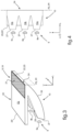
- a variant is possible and illustrated in diagram (a) of the figure 5 , in which the reflective face 19 is formed from a coating provided over the entire surface of the cut-off wall 20 facing the outside of the guide members 10.
- the output face 24 of the guide members 10 is flat, being oriented perpendicular to the cut-off wall 20, while in diagrams (b) and (c) of the figure 5 , the output face 24 of the guide members 10 is curved while being oriented in its general plane of extension perpendicular to the cut-off wall 20.
- the convexity of the domed conformation of the output face 24 of the guide members 10 is oriented towards the outside of the guide members 10, and that the curvature of said output face 24 is adapted so as not to obstruct the passage of the first cut-off beam F1 towards the projection device 3 and in particular the lens 4, not shown in the diagrams of the figure 5 .
- the guide has been shown according to a first series of variant embodiments, in which it is provided that the cut-off wall 20 is formed by integrating a plate 20' with the guide members.
- the plate 20' extends in a horizontal plane under which, with reference to the vertical arrangement resulting from the installation of the light module in a vehicle headlight, the guide members extend.
- the plate 20' has a proximal end which is formed in the continuity of the proximal end of the guide members carrying the output faces, and a distal end which extends partially at a distance d from the upper face 29 of the guide members 10, and more specifically at the rear of the guide members 10 in their longitudinal direction.
- Said upper face 29 is a face of the guide members 10 which can participate in guiding the light rays towards the exit face 24. It is understood that in this case, the cut-off wall 20 is specifically dedicated to the formation of the cover 8 providing the cut-off of the first beam F1.
- the wall cut-off wall 20 is produced in the longitudinal continuity of the upper face 29 of the guide members 10. It can therefore be understood that the cut-off wall participates on the one hand, by its face external to the guides, in the formation of the cut-off of the first beam F1, and on the other hand, by its face internal to the guides, in the routing of the light rays through the guide members 10 and towards their exit face 24. It should be noted that such arrangements are independent of the flat conformation (visible in diagram (d)) or curved (visible in diagrams (c) or (e)) of the exit wall 24 of the guide members 10.
- the cut-off wall 20 may comprise a first flat portion 31 comprising the reflective face 19 and which is extended towards the rear, in the longitudinal direction of the guide members 10, by a second portion 32 making the connection with the upper face 29 of the guide.
- This second portion 32 is in particular oriented along a general plane P3 intersecting the plane P1 of extension of the first portion 31.
- the second portion 32 of the cut-off wall 20 is potentially of flat conformation or of elliptical conformation whose concavity is oriented towards the inside of the guide members 10, such as in the illustrated embodiments.
- the upper face 29 can be substantially flat, as illustrated in diagrams (a) and (b) of the figure 5 , or it may have a slight curvature (diagrams (c) and (d)), it being noted that in all cases, the direct path of a light ray (illustrated in dotted lines in diagrams (a) to (d)) between the center of the entry face 27 and the exit edge 23 arranged substantially at the object focal point of the lens 4 is not hindered by the presence of this upper wall. This optimizes the transmission of these direct rays which make it possible to obtain a beam at the exit of the lens with high light intensity and with limited chromatic aberrations.
- the upper face 29 has a substantially elliptical shape in a longitudinal and vertical section plane of the guide.
- the elliptical shape of the upper face is such that a first focus is centered on the input face 27 of the optical guide and a second focus is centered on the output edge 23 of the output face 24.
- the exit face is widened so as to extend vertically over a greater height below the cut-off edge, and that the reflection face 30 is flattened, so as to easily control the production of light rays over a significant height in the focal plane of the projection device and the resulting creation of large light segments, it being understood that it is appropriate as previously described that the majority of the rays arrive on the exit face at the exit edge 23.
- the cut-off edge 22 and the exit edge 23 can be rigorously positioned fixed inside the light module, extending perpendicularly along the focal plane Pf and in the focal axis A of the projection device 3 and in particular of the lens 4.
Landscapes
- Engineering & Computer Science (AREA)
- General Engineering & Computer Science (AREA)
- Physics & Mathematics (AREA)
- Microelectronics & Electronic Packaging (AREA)
- Optics & Photonics (AREA)
- Non-Portable Lighting Devices Or Systems Thereof (AREA)
Claims (5)
- Beleuchtungsvorrichtung eines Kraftfahrzeugs, ein Leuchtmodul umfassend, das Leuchtmodul umfassend:- erste Mittel (1), die dazu gestaltet sind, ein erstes Bündel (F1) mit Hell-Dunkel-Grenze ausgehend von mindestens einer ersten Lichtquelle (6) zu realisieren, und- zweite Mittel (2), die dazu gestaltet sind, ein zweites Bündel (F2) zu bilden, das komplementär zu dem ersten Bündel (F1) mit Hell-Dunkel-Grenze ist, wenn sie gleichzeitig aktiviert sind, wobei die zweiten Mittel (2) eine Mehrzahl von zweiten Lichtquellen (9) und mindestens einen Lichtleiter (10) umfassen, um das komplementäre zweite Bündel zu bilden, wobei der mindestens eine Lichtleiter (10) eine Begrenzungswand (20) beinhaltet, die mit einer reflektierenden Fläche (19) versehen ist, die gegenüber den ersten Mitteln (1) angeordnet ist, wobei die reflektierende Fläche (19) eine Blende (8) bildet, die mindestens einen Teil der Hell-Dunkel-Grenze des ersten Bündels (F1) realisiert;wobei die zweiten Mittel (2) dazu gestaltet sind, mindestens zwei Leuchtsegmente (30) zu realisieren, die selektiv aktivierbar sind, um das zweite Bündel (F2) zu bilden, das komplementär zu dem ersten Bündel (F1) mit Hell-Dunkel-Grenze ist, wenn sie gleichzeitig aktiviert sind, wobei der mindestens eine Lichtleiter (10) Leitorgane zur Führung des Lichts umfasst, aus denen die Leuchtsemente hervorgehen, wobei die Leitorgane und die Begrenzungswand (20) eine einstückige Einheit bilden;wobei jedes Leuchtsegment des komplementären zweiten Bündels durch Zusammenwirken einer zweiten Lichtquelle (9) mit einem zugeordneten Leitorgan (10) erhalten wird, so dass eine Eintrittsfläche (27) des Leitorgans (10) das von der zweiten Lichtquelle (9) emittierte Licht empfängt,wobei die reflektierende Fläche (19) bündig mit einer Austrittskante (23) der Leitorgane (10) ist, die am Rand der Begrenzungswand (20) ausgebildet ist, wobei sich die Austrittskante (23) entlang der Begrenzungswand (20) und entlang einer Austrittsfläche (24) der Leitorgane (10) gemeinsam erstreckt,wobei sich die reflektierende Fläche (19) längs von einer vorderen Kante der Begrenzungswand des mindestens einen Lichtleiters (10) aus, die die Begrenzungskante (22) des ersten Bündels (F1) bildet, nach hinten erstreckt,dadurch gekennzeichnet, dass die Begrenzungswand (20) eine Wand des mindestens einen Lichtleiters (10) ist, die speziell zur Bildung der Blende (8) dediziert ist,und dass sich die Begrenzungswand (20) teilweise in einem Abstand (d) von mindestens einer oberen Wand (29) der Leitorgane (10) erstreckt.
- Beleuchtungsvorrichtung nach einem der vorhergehenden Ansprüche, dadurch gekennzeichnet, dass die Begrenzungswand (20) als Platte (20') gestaltet ist, die in die Leitorgane (10) integriert ist.
- Beleuchtungsvorrichtung nach einem der vorhergehenden Ansprüche, dadurch gekennzeichnet, dass sie eine Projektionsvorrichtung zur Projektion des ersten Bündels (F1) und des zweiten Bündels (F2) umfasst, wobei diese Projektionsvorrichtung den ersten und zweiten Mitteln gemeinsam zugeordnet ist, wobei die reflektierende Fläche (19) im Wesentlichen senkrecht zu der Brennebene (Pf) und in der Brennachse (A) der Projektionsvorrichtung (3) angeordnet ist.
- Beleuchtungsvorrichtung nach einem der vorhergehenden Ansprüche, dadurch gekennzeichnet, dass die Begrenzungswand (20) ein Montageorgan des oder der Lichtleiter (10) an einem Rahmen des Leuchtmoduls darstellt, das die ersten Mittel (1) und die zweiten Mittel (2) aufnimmt.
- Beleuchtungsvorrichtung nach einem der vorhergehenden Ansprüche, dadurch gekennzeichnet, dass die Vorrichtung ferner Projektionsmittel zur Projektion des ersten Bündels und des zweiten Bündels umfasst sowie allgemeine Steuerungsmittel, die ein erstes Steuerungsmittel aufweisen, das selektiv zum einen die Projektion des ersten Bündels mit Hell-Dunkel-Grenze, das ein Abblendlicht bildet, das von einem ersten Teilmodul erzeugt wird, steuert und zum anderen die Projektion eines Bündels, das ein Fernlicht bildet, das gemeinsam von dem ersten Teilmodul, welches das erste Bündel mit Hell-Dunkel-Grenze bildet, und von einem zweiten Teilmodul zur Erzeugung des zweiten Bündels, das zu dem ersten Bündel mit Hell-Dunkel-Grenze komplementär ist, erzeugt wird, wobei die allgemeinen Steuerungsmittel ferner ein zweites Steuerungsmittel zur selektiven Aktivierung mindestens einer der zweiten Lichtquellen der zweiten Mittel umfassen, um die Selektivität des Fernlichts anzusteuern.
Applications Claiming Priority (1)
| Application Number | Priority Date | Filing Date | Title |
|---|---|---|---|
| FR1556625A FR3038696B1 (fr) | 2015-07-10 | 2015-07-10 | Module lumineux pour l'eclairage et/ou la signalisation d'un vehicule automobile |
Publications (2)
| Publication Number | Publication Date |
|---|---|
| EP3115683A1 EP3115683A1 (de) | 2017-01-11 |
| EP3115683B1 true EP3115683B1 (de) | 2025-01-08 |
Family
ID=54366321
Family Applications (1)
| Application Number | Title | Priority Date | Filing Date |
|---|---|---|---|
| EP16177276.9A Active EP3115683B1 (de) | 2015-07-10 | 2016-06-30 | Leuchtvorrichtung zur beleuchtung für kraftfahrzeug |
Country Status (2)
| Country | Link |
|---|---|
| EP (1) | EP3115683B1 (de) |
| FR (1) | FR3038696B1 (de) |
Families Citing this family (7)
| Publication number | Priority date | Publication date | Assignee | Title |
|---|---|---|---|---|
| CN106641964B (zh) * | 2017-01-19 | 2023-05-16 | 华域视觉科技(上海)有限公司 | 一种具有adb功能的led光源远近光一体车灯模组 |
| KR102171391B1 (ko) * | 2017-01-19 | 2020-10-29 | 하스코 비전 테크놀로지 컴퍼니 리미티드 | Adb 기능이 있는 led 광원 하이-로우 빔 일체형 차량용 램프 모듈 |
| KR101938669B1 (ko) | 2017-06-22 | 2019-01-15 | 엘지전자 주식회사 | 차량용 램프 및 그것의 제어방법 |
| JP7143716B2 (ja) * | 2018-10-10 | 2022-09-29 | 市光工業株式会社 | 車両用導光体および車両用灯具 |
| CN113883469B (zh) * | 2020-07-02 | 2025-12-19 | 华域视觉科技(上海)有限公司 | 车灯光学单元、车灯模组和车辆 |
| CN214094302U (zh) * | 2020-12-01 | 2021-08-31 | 华域视觉科技(上海)有限公司 | 一种远光车灯光学元件、车辆远光照明单元、车灯及车辆 |
| WO2023282238A1 (ja) * | 2021-07-07 | 2023-01-12 | 株式会社小糸製作所 | 車両用灯具 |
Citations (1)
| Publication number | Priority date | Publication date | Assignee | Title |
|---|---|---|---|---|
| FR2995662A1 (fr) * | 2012-06-29 | 2014-03-21 | Valeo Vision | Module et dispositif d'eclairage pour vehicule automobile |
Family Cites Families (8)
| Publication number | Priority date | Publication date | Assignee | Title |
|---|---|---|---|---|
| FR2858042B1 (fr) * | 2003-07-24 | 2005-09-23 | Valeo Vision | Module d'eclairage elliptique sans cache realisant un faisceau d'eclairage a coupure et projecteur comportant un tel module |
| JP4413839B2 (ja) | 2005-09-13 | 2010-02-10 | 株式会社小糸製作所 | 車両用前照灯の灯具ユニット |
| JP5091808B2 (ja) * | 2008-09-02 | 2012-12-05 | 株式会社小糸製作所 | 車両用灯具 |
| DE102010021937A1 (de) * | 2010-05-28 | 2011-12-01 | Hella Kgaa Hueck & Co. | LED-Projektionsmodul für einen Fahrzeugscheinwerfer |
| AT512246B1 (de) * | 2011-11-22 | 2014-02-15 | Zizala Lichtsysteme Gmbh | Led-projektionsmodul und scheinwerfer mit modul |
| JP2013242996A (ja) * | 2012-05-18 | 2013-12-05 | Koito Mfg Co Ltd | 車両用前照灯 |
| FR2995967B1 (fr) * | 2012-09-24 | 2019-09-06 | Valeo Vision | Module d'eclairage, notamment pour vehicule automobile |
| FR3012203B1 (fr) * | 2013-10-23 | 2015-10-30 | Valeo Vision | Dispositif d'eclairage comportant un guide de rayons lumineux |
-
2015
- 2015-07-10 FR FR1556625A patent/FR3038696B1/fr active Active
-
2016
- 2016-06-30 EP EP16177276.9A patent/EP3115683B1/de active Active
Patent Citations (1)
| Publication number | Priority date | Publication date | Assignee | Title |
|---|---|---|---|---|
| FR2995662A1 (fr) * | 2012-06-29 | 2014-03-21 | Valeo Vision | Module et dispositif d'eclairage pour vehicule automobile |
Also Published As
| Publication number | Publication date |
|---|---|
| FR3038696B1 (fr) | 2022-02-18 |
| EP3115683A1 (de) | 2017-01-11 |
| FR3038696A1 (fr) | 2017-01-13 |
Similar Documents
| Publication | Publication Date | Title |
|---|---|---|
| EP3115683B1 (de) | Leuchtvorrichtung zur beleuchtung für kraftfahrzeug | |
| EP3002504B1 (de) | Leuchtmodul zur beleuchtung für kraftfahrzeug | |
| EP4235024B1 (de) | Leuchtvorrichtung, die die beleuchteten flächen von mindestens zwei kollektoren abbildet | |
| EP3067618B1 (de) | Leuchtvorrichtung mit optischen wellenleitern | |
| EP3604910B1 (de) | Optisches bauteil, das einen block mit einem diopter umfasst, der eine beugungseinheit für zwei lichtstrahlen bildet | |
| EP3167226B1 (de) | Beleuchtungsmodul für ein kraftfahrzeug | |
| EP1500869A1 (de) | Elliptische Beleuchtungseinheit ohne Lichtblende zur Erzeugung eines Abblendlichtbündels und Scheinwerfer mit einer derartigen Belleuchtungseinheit | |
| FR3035182A1 (fr) | Dispositif lumineux pour l'eclairage et/ou la signalisation d'un vehicule automobile | |
| EP2019258A1 (de) | Optisches Modul mit Lichtquelle für Scheinwerfer eines Kraftfahrzeugs | |
| EP2846081B1 (de) | Vorrichtung zur Beleuchtung und Signalisierung für Fahrzeuge | |
| EP2767752A1 (de) | Vorrichtung zur Beleuchtung und/oder Signalisierung mit torischer Linse | |
| EP2436968B1 (de) | Vorrichtung zur Ausstrahlung von Licht für einen Autoscheinwerfer | |
| FR3038695A1 (fr) | Module lumineux pour l'eclairage et/ou la signalisation d'un vehicule automobile | |
| EP1684004B1 (de) | Fahrzeugscheinwerfer mit zwei Beleuchtungsverteilungen | |
| FR3042846A1 (fr) | Dispositif lumineux a guides optiques | |
| EP1944542B1 (de) | Scheinwerfer mit zwei Funktionen für Kraftfahrzeug | |
| EP2799763B1 (de) | Fahrzeugscheinwerfer | |
| EP2770249A1 (de) | KFZ-Scheinwerfer | |
| EP1947380B1 (de) | Optisches Multifunktionsmodul für Kraftfahrzeug | |
| EP2927050A1 (de) | Leuchtvorrichtung mit ablenkbildschirm | |
| EP3271211B1 (de) | Beleuchtungs- und/oder signalisierungssystem für kraftfahrzeuge | |
| WO2024133454A1 (fr) | Module lumineux d'un dispositif d'éclairage et/ou de signalisation pour véhicule | |
| WO2024133404A1 (fr) | Dispositif lumineux comprenant une pluralité de modules | |
| FR3151379A1 (fr) | Dispositif lumineux d’éclairage et/ou de signalisation d’un véhicule automobile | |
| EP2947379A2 (de) | Elliptisches optisches modul für beleuchtungsvorrichtung eines kraftfahrzeugs |
Legal Events
| Date | Code | Title | Description |
|---|---|---|---|
| PUAI | Public reference made under article 153(3) epc to a published international application that has entered the european phase |
Free format text: ORIGINAL CODE: 0009012 |
|
| STAA | Information on the status of an ep patent application or granted ep patent |
Free format text: STATUS: THE APPLICATION HAS BEEN PUBLISHED |
|
| AK | Designated contracting states |
Kind code of ref document: A1 Designated state(s): AL AT BE BG CH CY CZ DE DK EE ES FI FR GB GR HR HU IE IS IT LI LT LU LV MC MK MT NL NO PL PT RO RS SE SI SK SM TR |
|
| AX | Request for extension of the european patent |
Extension state: BA ME |
|
| STAA | Information on the status of an ep patent application or granted ep patent |
Free format text: STATUS: REQUEST FOR EXAMINATION WAS MADE |
|
| 17P | Request for examination filed |
Effective date: 20170707 |
|
| RBV | Designated contracting states (corrected) |
Designated state(s): AL AT BE BG CH CY CZ DE DK EE ES FI FR GB GR HR HU IE IS IT LI LT LU LV MC MK MT NL NO PL PT RO RS SE SI SK SM TR |
|
| STAA | Information on the status of an ep patent application or granted ep patent |
Free format text: STATUS: EXAMINATION IS IN PROGRESS |
|
| 17Q | First examination report despatched |
Effective date: 20200414 |
|
| P01 | Opt-out of the competence of the unified patent court (upc) registered |
Effective date: 20230528 |
|
| REG | Reference to a national code |
Ref country code: DE Ref legal event code: R079 Free format text: PREVIOUS MAIN CLASS: F21S0008120000 Ipc: F21S0041663000 Ref country code: DE Ref legal event code: R079 Ref document number: 602016090879 Country of ref document: DE Free format text: PREVIOUS MAIN CLASS: F21S0008120000 Ipc: F21S0041663000 |
|
| GRAP | Despatch of communication of intention to grant a patent |
Free format text: ORIGINAL CODE: EPIDOSNIGR1 |
|
| STAA | Information on the status of an ep patent application or granted ep patent |
Free format text: STATUS: GRANT OF PATENT IS INTENDED |
|
| RIC1 | Information provided on ipc code assigned before grant |
Ipc: F21S 41/148 20180101ALI20240426BHEP Ipc: F21S 41/147 20180101ALI20240426BHEP Ipc: F21S 41/151 20180101ALI20240426BHEP Ipc: F21S 41/24 20180101ALI20240426BHEP Ipc: F21S 41/43 20180101ALI20240426BHEP Ipc: F21S 41/663 20180101AFI20240426BHEP |
|
| INTG | Intention to grant announced |
Effective date: 20240522 |
|
| GRAS | Grant fee paid |
Free format text: ORIGINAL CODE: EPIDOSNIGR3 |
|
| GRAA | (expected) grant |
Free format text: ORIGINAL CODE: 0009210 |
|
| STAA | Information on the status of an ep patent application or granted ep patent |
Free format text: STATUS: THE PATENT HAS BEEN GRANTED |
|
| AK | Designated contracting states |
Kind code of ref document: B1 Designated state(s): AL AT BE BG CH CY CZ DE DK EE ES FI FR GB GR HR HU IE IS IT LI LT LU LV MC MK MT NL NO PL PT RO RS SE SI SK SM TR |
|
| REG | Reference to a national code |
Ref country code: GB Ref legal event code: FG4D Free format text: NOT ENGLISH |
|
| REG | Reference to a national code |
Ref country code: CH Ref legal event code: EP |
|
| REG | Reference to a national code |
Ref country code: DE Ref legal event code: R096 Ref document number: 602016090879 Country of ref document: DE |
|
| REG | Reference to a national code |
Ref country code: IE Ref legal event code: FG4D Free format text: LANGUAGE OF EP DOCUMENT: FRENCH |
|
| REG | Reference to a national code |
Ref country code: LT Ref legal event code: MG9D |
|
| REG | Reference to a national code |
Ref country code: NL Ref legal event code: MP Effective date: 20250108 |
|
| REG | Reference to a national code |
Ref country code: AT Ref legal event code: MK05 Ref document number: 1758537 Country of ref document: AT Kind code of ref document: T Effective date: 20250108 |
|
| PG25 | Lapsed in a contracting state [announced via postgrant information from national office to epo] |
Ref country code: NL Free format text: LAPSE BECAUSE OF FAILURE TO SUBMIT A TRANSLATION OF THE DESCRIPTION OR TO PAY THE FEE WITHIN THE PRESCRIBED TIME-LIMIT Effective date: 20250108 |
|
| PG25 | Lapsed in a contracting state [announced via postgrant information from national office to epo] |
Ref country code: RS Free format text: LAPSE BECAUSE OF FAILURE TO SUBMIT A TRANSLATION OF THE DESCRIPTION OR TO PAY THE FEE WITHIN THE PRESCRIBED TIME-LIMIT Effective date: 20250408 |
|
| PG25 | Lapsed in a contracting state [announced via postgrant information from national office to epo] |
Ref country code: FI Free format text: LAPSE BECAUSE OF FAILURE TO SUBMIT A TRANSLATION OF THE DESCRIPTION OR TO PAY THE FEE WITHIN THE PRESCRIBED TIME-LIMIT Effective date: 20250108 |
|
| PG25 | Lapsed in a contracting state [announced via postgrant information from national office to epo] |
Ref country code: PL Free format text: LAPSE BECAUSE OF FAILURE TO SUBMIT A TRANSLATION OF THE DESCRIPTION OR TO PAY THE FEE WITHIN THE PRESCRIBED TIME-LIMIT Effective date: 20250108 |
|
| PGFP | Annual fee paid to national office [announced via postgrant information from national office to epo] |
Ref country code: DE Payment date: 20250617 Year of fee payment: 10 |
|
| PG25 | Lapsed in a contracting state [announced via postgrant information from national office to epo] |
Ref country code: ES Free format text: LAPSE BECAUSE OF FAILURE TO SUBMIT A TRANSLATION OF THE DESCRIPTION OR TO PAY THE FEE WITHIN THE PRESCRIBED TIME-LIMIT Effective date: 20250108 |
|
| PG25 | Lapsed in a contracting state [announced via postgrant information from national office to epo] |
Ref country code: NO Free format text: LAPSE BECAUSE OF FAILURE TO SUBMIT A TRANSLATION OF THE DESCRIPTION OR TO PAY THE FEE WITHIN THE PRESCRIBED TIME-LIMIT Effective date: 20250408 Ref country code: IS Free format text: LAPSE BECAUSE OF FAILURE TO SUBMIT A TRANSLATION OF THE DESCRIPTION OR TO PAY THE FEE WITHIN THE PRESCRIBED TIME-LIMIT Effective date: 20250508 |
|
| PG25 | Lapsed in a contracting state [announced via postgrant information from national office to epo] |
Ref country code: HR Free format text: LAPSE BECAUSE OF FAILURE TO SUBMIT A TRANSLATION OF THE DESCRIPTION OR TO PAY THE FEE WITHIN THE PRESCRIBED TIME-LIMIT Effective date: 20250108 |
|
| PG25 | Lapsed in a contracting state [announced via postgrant information from national office to epo] |
Ref country code: LV Free format text: LAPSE BECAUSE OF FAILURE TO SUBMIT A TRANSLATION OF THE DESCRIPTION OR TO PAY THE FEE WITHIN THE PRESCRIBED TIME-LIMIT Effective date: 20250108 Ref country code: PT Free format text: LAPSE BECAUSE OF FAILURE TO SUBMIT A TRANSLATION OF THE DESCRIPTION OR TO PAY THE FEE WITHIN THE PRESCRIBED TIME-LIMIT Effective date: 20250508 |
|
| PGFP | Annual fee paid to national office [announced via postgrant information from national office to epo] |
Ref country code: FR Payment date: 20250630 Year of fee payment: 10 |
|
| PG25 | Lapsed in a contracting state [announced via postgrant information from national office to epo] |
Ref country code: BG Free format text: LAPSE BECAUSE OF FAILURE TO SUBMIT A TRANSLATION OF THE DESCRIPTION OR TO PAY THE FEE WITHIN THE PRESCRIBED TIME-LIMIT Effective date: 20250108 Ref country code: GR Free format text: LAPSE BECAUSE OF FAILURE TO SUBMIT A TRANSLATION OF THE DESCRIPTION OR TO PAY THE FEE WITHIN THE PRESCRIBED TIME-LIMIT Effective date: 20250409 |
|
| PG25 | Lapsed in a contracting state [announced via postgrant information from national office to epo] |
Ref country code: AT Free format text: LAPSE BECAUSE OF FAILURE TO SUBMIT A TRANSLATION OF THE DESCRIPTION OR TO PAY THE FEE WITHIN THE PRESCRIBED TIME-LIMIT Effective date: 20250108 |
|
| PG25 | Lapsed in a contracting state [announced via postgrant information from national office to epo] |
Ref country code: SE Free format text: LAPSE BECAUSE OF FAILURE TO SUBMIT A TRANSLATION OF THE DESCRIPTION OR TO PAY THE FEE WITHIN THE PRESCRIBED TIME-LIMIT Effective date: 20250108 |
|
| PG25 | Lapsed in a contracting state [announced via postgrant information from national office to epo] |
Ref country code: SM Free format text: LAPSE BECAUSE OF FAILURE TO SUBMIT A TRANSLATION OF THE DESCRIPTION OR TO PAY THE FEE WITHIN THE PRESCRIBED TIME-LIMIT Effective date: 20250108 |
|
| REG | Reference to a national code |
Ref country code: DE Ref legal event code: R097 Ref document number: 602016090879 Country of ref document: DE |
|
| PG25 | Lapsed in a contracting state [announced via postgrant information from national office to epo] |
Ref country code: DK Free format text: LAPSE BECAUSE OF FAILURE TO SUBMIT A TRANSLATION OF THE DESCRIPTION OR TO PAY THE FEE WITHIN THE PRESCRIBED TIME-LIMIT Effective date: 20250108 |
|
| PG25 | Lapsed in a contracting state [announced via postgrant information from national office to epo] |
Ref country code: EE Free format text: LAPSE BECAUSE OF FAILURE TO SUBMIT A TRANSLATION OF THE DESCRIPTION OR TO PAY THE FEE WITHIN THE PRESCRIBED TIME-LIMIT Effective date: 20250108 Ref country code: CZ Free format text: LAPSE BECAUSE OF FAILURE TO SUBMIT A TRANSLATION OF THE DESCRIPTION OR TO PAY THE FEE WITHIN THE PRESCRIBED TIME-LIMIT Effective date: 20250108 |
|
| PG25 | Lapsed in a contracting state [announced via postgrant information from national office to epo] |
Ref country code: RO Free format text: LAPSE BECAUSE OF FAILURE TO SUBMIT A TRANSLATION OF THE DESCRIPTION OR TO PAY THE FEE WITHIN THE PRESCRIBED TIME-LIMIT Effective date: 20250108 |
|
| PG25 | Lapsed in a contracting state [announced via postgrant information from national office to epo] |
Ref country code: SK Free format text: LAPSE BECAUSE OF FAILURE TO SUBMIT A TRANSLATION OF THE DESCRIPTION OR TO PAY THE FEE WITHIN THE PRESCRIBED TIME-LIMIT Effective date: 20250108 |
|
| PLBE | No opposition filed within time limit |
Free format text: ORIGINAL CODE: 0009261 |
|
| STAA | Information on the status of an ep patent application or granted ep patent |
Free format text: STATUS: NO OPPOSITION FILED WITHIN TIME LIMIT |
|
| REG | Reference to a national code |
Ref country code: CH Ref legal event code: L10 Free format text: ST27 STATUS EVENT CODE: U-0-0-L10-L00 (AS PROVIDED BY THE NATIONAL OFFICE) Effective date: 20251119 |
|
| 26N | No opposition filed |
Effective date: 20251009 |
|
| REG | Reference to a national code |
Ref country code: CH Ref legal event code: H13 Free format text: ST27 STATUS EVENT CODE: U-0-0-H10-H13 (AS PROVIDED BY THE NATIONAL OFFICE) Effective date: 20260127 |
|
| PG25 | Lapsed in a contracting state [announced via postgrant information from national office to epo] |
Ref country code: IT Free format text: LAPSE BECAUSE OF FAILURE TO SUBMIT A TRANSLATION OF THE DESCRIPTION OR TO PAY THE FEE WITHIN THE PRESCRIBED TIME-LIMIT Effective date: 20250108 |
|
| PG25 | Lapsed in a contracting state [announced via postgrant information from national office to epo] |
Ref country code: MC Free format text: LAPSE BECAUSE OF FAILURE TO SUBMIT A TRANSLATION OF THE DESCRIPTION OR TO PAY THE FEE WITHIN THE PRESCRIBED TIME-LIMIT Effective date: 20250108 |
|
| PG25 | Lapsed in a contracting state [announced via postgrant information from national office to epo] |
Ref country code: LU Free format text: LAPSE BECAUSE OF NON-PAYMENT OF DUE FEES Effective date: 20250630 |
|
| GBPC | Gb: european patent ceased through non-payment of renewal fee |
Effective date: 20250630 |
|
| REG | Reference to a national code |
Ref country code: BE Ref legal event code: MM Effective date: 20250630 |
|
| PG25 | Lapsed in a contracting state [announced via postgrant information from national office to epo] |
Ref country code: GB Free format text: LAPSE BECAUSE OF NON-PAYMENT OF DUE FEES Effective date: 20250630 |
|
| PG25 | Lapsed in a contracting state [announced via postgrant information from national office to epo] |
Ref country code: IE Free format text: LAPSE BECAUSE OF NON-PAYMENT OF DUE FEES Effective date: 20250630 |
|
| PG25 | Lapsed in a contracting state [announced via postgrant information from national office to epo] |
Ref country code: BE Free format text: LAPSE BECAUSE OF NON-PAYMENT OF DUE FEES Effective date: 20250630 |
|
| PG25 | Lapsed in a contracting state [announced via postgrant information from national office to epo] |
Ref country code: CH Free format text: LAPSE BECAUSE OF NON-PAYMENT OF DUE FEES Effective date: 20250630 |