EP3115518A1 - Sanitärarmatur mit zwei ventilen - Google Patents
Sanitärarmatur mit zwei ventilen Download PDFInfo
- Publication number
- EP3115518A1 EP3115518A1 EP16001353.8A EP16001353A EP3115518A1 EP 3115518 A1 EP3115518 A1 EP 3115518A1 EP 16001353 A EP16001353 A EP 16001353A EP 3115518 A1 EP3115518 A1 EP 3115518A1
- Authority
- EP
- European Patent Office
- Prior art keywords
- valve
- flow path
- sanitary fitting
- mixing unit
- fitting
- Prior art date
- Legal status (The legal status is an assumption and is not a legal conclusion. Google has not performed a legal analysis and makes no representation as to the accuracy of the status listed.)
- Granted
Links
Images


Classifications
-
- E—FIXED CONSTRUCTIONS
- E03—WATER SUPPLY; SEWERAGE
- E03C—DOMESTIC PLUMBING INSTALLATIONS FOR FRESH WATER OR WASTE WATER; SINKS
- E03C1/00—Domestic plumbing installations for fresh water or waste water; Sinks
- E03C1/02—Plumbing installations for fresh water
- E03C1/05—Arrangements of devices on wash-basins, baths, sinks, or the like for remote control of taps
- E03C1/055—Electrical control devices, e.g. with push buttons, control panels or the like
- E03C1/057—Electrical control devices, e.g. with push buttons, control panels or the like touchless, i.e. using sensors
-
- E—FIXED CONSTRUCTIONS
- E03—WATER SUPPLY; SEWERAGE
- E03C—DOMESTIC PLUMBING INSTALLATIONS FOR FRESH WATER OR WASTE WATER; SINKS
- E03C1/00—Domestic plumbing installations for fresh water or waste water; Sinks
- E03C1/02—Plumbing installations for fresh water
- E03C1/04—Water-basin installations specially adapted to wash-basins or baths
-
- E—FIXED CONSTRUCTIONS
- E03—WATER SUPPLY; SEWERAGE
- E03C—DOMESTIC PLUMBING INSTALLATIONS FOR FRESH WATER OR WASTE WATER; SINKS
- E03C1/00—Domestic plumbing installations for fresh water or waste water; Sinks
- E03C1/02—Plumbing installations for fresh water
- E03C1/04—Water-basin installations specially adapted to wash-basins or baths
- E03C1/0412—Constructional or functional features of the faucet handle
-
- F—MECHANICAL ENGINEERING; LIGHTING; HEATING; WEAPONS; BLASTING
- F16—ENGINEERING ELEMENTS AND UNITS; GENERAL MEASURES FOR PRODUCING AND MAINTAINING EFFECTIVE FUNCTIONING OF MACHINES OR INSTALLATIONS; THERMAL INSULATION IN GENERAL
- F16K—VALVES; TAPS; COCKS; ACTUATING-FLOATS; DEVICES FOR VENTING OR AERATING
- F16K31/00—Actuating devices; Operating means; Releasing devices
- F16K31/02—Actuating devices; Operating means; Releasing devices electric; magnetic
- F16K31/06—Actuating devices; Operating means; Releasing devices electric; magnetic using a magnet, e.g. diaphragm valves, cutting off by means of a liquid
-
- E—FIXED CONSTRUCTIONS
- E03—WATER SUPPLY; SEWERAGE
- E03C—DOMESTIC PLUMBING INSTALLATIONS FOR FRESH WATER OR WASTE WATER; SINKS
- E03C1/00—Domestic plumbing installations for fresh water or waste water; Sinks
- E03C1/02—Plumbing installations for fresh water
- E03C2001/026—Plumbing installations for fresh water with flow restricting devices
Definitions
- the present invention relates to a sanitary fitting, for example in the manner of a mixer tap or mixing fitting, which serves in particular the mixing of cold water and hot water to a mixed water having a desired mixed water temperature.
- sanitary fittings for example in the manner of a mixer tap or mixing fitting, which serves in particular the mixing of cold water and hot water to a mixed water having a desired mixed water temperature.
- the most common use of sanitary fittings is on sinks, sinks, showers and / or bathtubs.
- a sanitary fitting with two shut-off valves is known.
- a first shut-off valve is a manual valve which can be actuated conventionally via a lever of the sanitary fitting.
- the second shut-off valve is electronically controlled and actuated by means of a capacitive sensor.
- a water flow is therefore on the one hand activated conventionally via the mechanical lever or by simply touching the sanitary fitting.
- a disadvantage of this sanitary fitting is that for activating the flow of water through the capacitive sensor, the first shut-off valve must be manually opened via the lever. Consequently, the water flow can not be activated by the capacitive sensor independently of the first shut-off valve.
- the object of the invention is therefore to solve the problems described with reference to the prior art at least partially and in particular to provide a sanitary fitting, in which an improved water flow or easier handling is possible.
- the sanitary fitting should be as robust and compact as possible and inexpensive to produce.
- the sanitary fitting has a fitting housing with at least one mixing unit for mixing a cold water and a hot water to a mixed water, wherein the mixed water via a first flow path and a second flow path to an outlet of the valve body is conductive and wherein the first flow path through a first valve and the second flow path through a second valve is at least partially closed, so that independently of each other, an outflow of the mixed water is controlled from the outlet by the first valve and the second valve.
- the sanitary fitting is designed, for example, in the manner of a mixer tap or mixing fitting and is used in particular on wax basins, sinks, showers and / or bathtubs.
- the sanitary fitting has a fitting housing with at least one mixing unit for mixing a cold water and a hot water to a mixed water.
- the fitting housing is in particular at least partially made of metal, such as a brass alloy.
- the at least one mixing unit is supplied via a cold water inlet cold water and hot water via a hot water supply.
- the cold water has in particular a temperature of 0 ° C - 40 ° C and / or the hot water has a temperature of 40 ° C - 90 ° C.
- the cold water and the hot water are mixed in the at least one mixed water unit to a mixed water having a desired mixed water temperature.
- the mixed water is conducted via a first flow path and a second flow path to an outlet of the fitting housing.
- the first flow path and / or the second flow path may be, for example, channels in the fitting housing or in the fitting housing act guided (hose) lines.
- the first flow path is closed by means of a first valve and the second flow path by means of a second valve at least partially (in particular completely), so that independently of each other a drainage of the mixed water is controlled from the outlet by the first valve and the second valve.
- the first valve can be arranged in the first flow path and / or the second valve in the second flow path.
- the mixed water can thus be directed in particular via the first flow path and / or the second flow path from the at least one mixing unit to the outlet of the valve body.
- the outflow of the mixed water from the outlet of the valve body can therefore be controlled independently by either the first valve or the second valve.
- the first valve is an electrical valve, an electromechanical valve or a solenoid valve.
- the first valve is electrically controllable.
- the first valve may in particular have a servomotor for this purpose.
- the solenoid valve is in particular a valve which can be actuated by an electromagnet.
- the first valve can be controlled by at least one sensor.
- the sensor may be, for example, an infrared sensor, a capacitive sensor and / or a switch.
- the sensor can be arranged directly on the valve body.
- the sensor can transmit a sensor signal to a controller, for example in the manner of a microprocessor, by means of which the first valve is controlled.
- the senor is arranged outside the sanitary fitting.
- the sensor can in this case, for example, a faucet, a sink, a sink, a shower or a bath.
- the sensor can be placed in particular such that it is particularly easy to reach by a user of the sanitary fitting.
- the sensor is regularly arranged at least partially or completely within the sanitary fitting.
- the second valve is a mechanical valve, a mixing cartridge or a second mixing unit.
- a mechanical valve the activation or movement of the valve takes place (only) with a mechanism, e.g. using levers, gears, discs, eccentrics, connecting rods, etc.
- the second valve can be actuated with an actuator.
- the actuator is arranged in particular on the valve body and actuated by a user.
- the actuator is in particular an opening and / or closing of the second valve possible.
- a desired mixed water temperature of the mixed water can be selected.
- the actuator may in particular be at least one lever and / or at least one handle.
- the actuator is also arranged in particular on the valve body.
- first valve and the second valve are connected in parallel to one another and in each case in series with a first mixing unit.
- a first mixing unit and the first valve are connected in series and wherein the first mixing unit and the first valve are connected in parallel to the second valve.
- the Fig. 1 shows a sanitary fitting 1 with a fitting housing 2.
- the sanitary fitting 1 has a first mixing unit 3, which is supplied via a cold water inlet 12 cold water and a hot water inlet 13 hot water.
- the first mixing unit 3 in this embodiment is a mechanical mixing valve.
- the cold water and the hot water are mixed to a mixed water having a desired mixed water temperature.
- the mixed water mixed by the first mixing unit 3 can be conducted via a first flow path 5 and a second flow path 6 to an outlet 7 of the fitting housing 2.
- the first flow path 5 is at least partially closed by a first valve 8 and the second flow path 6 through a second valve 9.
- the first valve 8 and the second valve 9 are connected in parallel to one another and in each case in series with the first mixing unit 3.
- the first valve 8 in this embodiment is a solenoid valve.
- the first valve 8 is data-conducting connected to a sensor 10, which is a capacitive sensor here.
- the second valve 9 is a mechanical valve which can be actuated by an actuator 11, which is designed here by way of example in the manner of a lever.
- the outflow of the mixed water from the outlet 7 of the valve body 2 is thus independently controlled by the first valve 8 and the second valve 9.
- the Fig. 2 shows a sanitary fitting 1 with a fitting housing 2.
- the sanitary fitting has a first mixing unit 3 and a second mixing unit 4.
- the first mixing unit 3 and the second mixing unit 4 is fed via a cold water inlet 12 cold water and a hot water inlet 13 hot water.
- the cold water and the hot water are mixed in the first mixing unit 3 and the second mixing unit 4 independently of each other to a mixed water having a desired mixed water temperature.
- the mixed water mixed by the first mixing unit 3 can be conducted via a first flow path 5 to an outlet 7 of the fitting housing 2.
- the mixing water mixed by the second mixing unit 4 can be conducted via a second flow path 6 to the outlet 7 of the fitting housing 2.
- the first flow path 5 is at least partially closed by a first valve 8.
- the first valve 8 is also a solenoid valve, which is data-conducting connected to a sensor 10.
- the sensor 10 is a capacitive sensor.
- the second mixing unit 4 has an integrated second valve 9, with which the second flow path 6 is at least partially closed.
- the second valve 9 is actuated by a lever 11 by a user of the sanitary fitting 1.
- the first mixing unit 3 and the first valve 8 are connected in series.
- the first mixing unit 3 and the first valve 8 are connected in parallel to the second valve 9 and the second mixing unit 4.
- an outflow of the mixed water from the outlet 7 can be controlled independently of each other by the first valve 8 and the second valve 9.
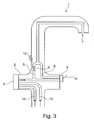
- the Fig. 3 shows a sanitary fitting 1 with a fitting housing 2.
- the fitting housing 2 has a first mixing unit 3, which is supplied via a cold water inlet 12 cold water and a hot water inlet 13 hot water.
- the first mixing unit 3 is a thermostatic mixing unit in which the cold water and the hot water are mixed to form a mixed water having a desired mixed water temperature.
- the mixed water can be supplied from the first mixing unit 3 via a first flow path 5 and a second flow path 6 to an outlet 7 of the fitting housing 2.
- the first Flow path 5 is at least partially closed by a first valve 8 and the second flow path 6 through a second valve 9.
- the first valve 8 is a solenoid valve which is connected to a sensor 10 for data conduction.
- the sensor 10 is a capacitive sensor.
- the second valve 9 is a mechanical valve which can be actuated by a user of the sanitary fitting 1 by means of a lever 11.
- the first valve 8 and the second valve 9 are connected in parallel to one another and in each case in series with the first mixing unit 3.
- an outflow of the mixed water from the outlet 7 can be controlled.
- the present invention is characterized in particular by the fact that an outflow of the mixed water through two valves can be controlled independently of one another.
Landscapes
- Engineering & Computer Science (AREA)
- Health & Medical Sciences (AREA)
- Life Sciences & Earth Sciences (AREA)
- Hydrology & Water Resources (AREA)
- Public Health (AREA)
- Water Supply & Treatment (AREA)
- General Engineering & Computer Science (AREA)
- Mechanical Engineering (AREA)
- Domestic Plumbing Installations (AREA)
- Multiple-Way Valves (AREA)
Abstract
Description
- Die vorliegende Erfindung betrifft eine Sanitärarmatur, beispielsweise nach Art einer Mischbatterie oder Mischarmatur, die insbesondere dem Mischen von Kaltwasser und Warmwasser zu einem Mischwasser mit einer gewünschten Mischwassertemperatur dient. Die gebräuchlichste Verwendung von Sanitärarmaturen ist die an Waschbecken, Spülbecken, Duschen und/oder Badewannen.
- Aus der
US 2010/0170570 A1 ist beispielsweise eine Sanitärarmatur mit zwei Absperrventilen bekannt. Bei einem ersten Absperrventil handelt es sich um ein manuelles Ventil, das über einen Hebel der Sanitärarmatur konventionell betätigbar ist. Das zweite Absperrventil ist elektronisch gesteuert und mittels eines kapazitiven Sensors betätigbar. Ein Wasserfluss ist somit einerseits konventionell über den mechanischen Hebel oder durch einfaches Berühren der Sanitärarmatur aktivierbar. Nachteilig an dieser Sanitärarmatur ist, dass für das Aktivieren des Wasserflusses über den kapazitiven Sensor das erste Absperrventil über den Hebel manuell offengestellt sein muss. Der Wasserfluss ist folglich durch den kapazitiven Sensor nicht unabhängig von dem ersten Absperrventil aktivierbar. - Aufgabe der Erfindung ist es daher, die mit Bezug auf den Stand der Technik geschilderten Probleme zumindest teilweise zu lösen und insbesondere eine Sanitärarmatur anzugeben, bei der ein verbesserter Wasserfluss bzw. eine einfachere Handhabung ermöglicht wird. Dabei soll die Sanitärarmatur möglichst robust und kompakt aufgebaut sowie kostengünstig herstellbar sein.
- Diese Aufgaben werden gelöst mit einer Sanitärarmatur gemäß den Merkmalen des unabhängigen Patentanspruchs. Weitere vorteilhafte Ausgestaltungen der Sanitärarmatur sind in den abhängig formulierten Patentansprüchen angegeben. Es ist darauf hinzuweisen, dass die in den abhängig formulierten Patentansprüchen einzeln aufgeführten Merkmale in beliebiger technologisch sinnvoller Weise miteinander kombiniert werden können und weitere Ausgestaltungen der Erfindung definieren. Darüber hinaus werden die in den Patentansprüchen angegeben Merkmale in der Beschreibung näher präzisiert und erläutert, wobei weitere bevorzugte Ausgestaltungen der Erfindung dargestellt werden.
- Die Sanitärarmatur weist ein Armaturengehäuse mit zumindest einer Mischeinheit zum Mischen eines Kaltwassers und eines Warmwassers zu einem Mischwasser auf, wobei das Mischwasser über einen ersten Strömungspfad und einen zweiten Strömungspfad zu einem Auslauf des Armaturengehäuses leitbar ist und wobei der erste Strömungspfad durch ein erstes Ventil und der zweite Strömungspfad durch ein zweites Ventil zumindest teilweise verschließbar ist, sodass durch das erste Ventil und das zweite Ventil unabhängig voneinander ein Abfluss des Mischwassers aus dem Auslauf steuerbar ist.
- Die Sanitärarmatur ist beispielsweise nach Art einer Mischbatterie oder Mischarmatur ausgestaltet und wird insbesondere an Wachbecken, Spülbecken, Duschen und/oder Badewannen verwendet. Die Sanitärarmatur weist ein Armaturengehäuse mit zumindest einer Mischeinheit zum Mischen eines Kaltwassers und eines Warmwasser zu einem Mischwasser auf. Das Armaturengehäuse besteht insbesondere zumindest teilweise aus Metall, wie beispielsweise aus einer Messinglegierung. Der zumindest einen Mischeinheit wird über einen Kaltwasserzulauf Kaltwasser und über einen Warmwasserzulauf Warmwasser zugeführt. Das Kaltwasser weist insbesondere eine Temperatur von 0 °C - 40 °C und/oder das Warmwasser eine Temperatur von 40 °C - 90 °C auf. Das Kaltwasser und das Warmwasser werden in der zumindest einen Mischwassereinheit zu einem Mischwasser mit einer gewünschten Mischwassertemperatur gemischt. Ausgehend von der zumindest einen Mischeinheit wird das Mischwasser über einen ersten Strömungspfad und einen zweiten Strömungspfad zu einem Auslauf des Armaturengehäuses geleitet. Bei dem ersten Strömungspfad und/oder dem zweiten Strömungspfad kann es sich beispielsweise um Kanäle in dem Armaturengehäuse oder um in dem Armaturengehäuse geführte (Schlauch-)Leitungen handeln. Der erste Strömungspfad ist mittels eines ersten Ventils und der zweite Strömungspfad mittels eines zweiten Ventils zumindest teilweise (insbesondere auch vollständig) verschließbar, sodass durch das erste Ventil und das zweite Ventil unabhängig voneinander ein Abfluss des Mischwassers aus dem Auslauf steuerbar ist. Somit kann mittels voreingestellter Positionen des ersten Ventils und/oder des zweiten Ventils ein Wasserfluss durch den ersten Strömungspfad und/oder den zweiten Strömungspfad (vollständig oder reduziert) zugelassen und/oder unterbunden werden. Das erste Ventil kann hierzu in dem ersten Strömungspfad und/oder das zweite Ventil in dem zweiten Strömungspfad angeordnet sein. Das Mischwasser kann somit insbesondere über den ersten Strömungspfad und/oder den zweiten Strömungspfad von der zumindest einen Mischeinheit zu dem Auslauf des Armaturengehäuses geleitet werden. Der Abfluss des Mischwassers aus dem Auslauf des Armaturengehäuses kann daher entweder durch das erste Ventil oder das zweite Ventil unabhängig gesteuert werden.
- Zudem ist es vorteilhaft, wenn es sich bei dem ersten Ventil um ein elektrisches Ventil, ein elektromechanisches Ventil oder ein Magnetventil handelt. Dies bedeutet insbesondere, dass das erste Ventil elektrisch steuerbar ist. Das erste Ventil kann hierzu insbesondere einen Stellmotor aufweisen. Bei dem Magnetventil handelt es sich insbesondere um ein Ventil, das von einem Elektromagneten betätigbar ist.
- Ebenfalls vorteilhaft ist es, wenn das erste Ventil durch mindestens einen Sensor steuerbar ist. Bei dem Sensor kann es sich beispielsweise um einen Infrarotsensor, einen kapazitiven Sensor und/oder einen Schalter handeln. Der Sensor kann direkt an dem Armaturengehäuse angeordnet sein. Insbesondere kann der Sensor ein Sensorsignal an eine Steuerung, beispielsweise nach Art eines Mikroprozessors, übertragen, durch den das erste Ventil gesteuert wird.
- Darüber hinaus ist es vorteilhaft, wenn der Sensor außerhalb der Sanitärarmatur angeordnet ist. Der Sensor kann in diesem Fall beispielsweise an einem Wasserhahn, einem Waschbecken, einem Spülbecken, einer Dusche oder einer Badewanne angeordnet sein. Hierdurch kann der Sensor insbesondere derart platziert werden, dass dieser durch einen Benutzer der Sanitärarmatur besonders leicht zu erreichen ist. Der Sensor ist jedoch regelmäßig zumindest teilweise oder vollständig innerhalb der Sanitärarmatur angeordnet.
- Darüber hinaus ist es vorteilhaft, wenn es sich bei dem zweiten Ventil um ein mechanisches Ventil, eine Mischkartusche oder eine zweite Mischeinheit handelt. Bei einem mechanischen Ventil erfolgt die Aktivierung bzw. Bewegung des Ventils (nur) mit einer Mechanik, also z.B. unter Einsatz von Hebeln, Zahnrädern, Scheiben, Exzenter, Pleuel, etc.
- Ebenfalls vorteilhaft ist es, wenn das zweite Ventil mit einem Stellglied betätigbar ist. Das Stellglied ist insbesondere an dem Armaturengehäuse angeordnet und durch einen Benutzer betätigbar. Mittels des Stellglieds ist insbesondere ein Öffnen und/oder Schließen des zweiten Ventils möglich. Zudem kann durch das Stellglied insbesondere auch eine gewünschte Mischwassertemperatur des Mischwassers gewählt werden. Bei dem Stellglied kann es sich insbesondere um zumindest einen Hebel und/oder um zumindest einen Griff handeln. Das Stellglied ist zudem insbesondere an dem Armaturengehäuse angeordnet.
- Zudem ist es vorteilhaft, wenn das erste Ventil und das zweite Ventil parallel zueinander und jeweils in Reihe mit einer ersten Mischeinheit geschaltet sind.
- Darüber hinaus ist es vorteilhaft, wenn eine erste Mischeinheit und das erste Ventil in Reihe geschaltet sind und wobei die erste Mischeinheit und das erste Ventil parallel zu dem zweiten Ventil geschaltet sind.
- Die Erfindung sowie das technische Umfeld werden nachfolgend anhand der Figuren näher erläutert. Es ist darauf hinzuweisen, dass die Figuren besonders bevorzugte Ausführungsvarianten der Erfindung zeigen, diese jedoch nicht darauf beschränkt ist. Dabei sind gleiche Bauteile in den Figuren mit denselben Bezugszeichen versehen. Es zeigen schematisch:
- Fig. 1:
- eine erste Ausführungsvariante der Sanitärarmatur;
- Fig. 2:
- eine zweite Ausführungsvariante der Sanitärarmatur; und
- Fig. 3:
- eine dritte Ausführungsvariante der Sanitärarmatur.
- Die
Fig. 1 zeigt eine Sanitärarmatur 1 mit einem Armaturengehäuse 2. Die Sanitärarmatur 1 weist eine erste Mischeinheit 3 auf, der über einen Kaltwasserzulauf 12 Kaltwasser und einem Warmwasserzulauf 13 Warmwasser zugeführt wird. Bei der ersten Mischeinheit 3 handelt es sich bei dieser Ausführungsvariante um ein mechanisches Mischventil. In der ersten Mischeinheit 3 werden das Kaltwasser und das Warmwasser zu einem Mischwasser mit einer gewünschten Mischwassertemperatur gemischt. Das durch die erste Mischeinheit 3 gemischte Mischwasser ist über einen ersten Strömungspfad 5 und einen zweiten Strömungspfad 6 zu einem Auslauf 7 des Armaturengehäuses 2 leitbar. Der erste Strömungspfad 5 ist durch ein erstes Ventil 8 und der zweite Strömungspfad 6 durch ein zweites Ventil 9 zumindest teilweise verschließbar. Das erste Ventil 8 und das zweite Ventil 9 sind parallel zueinander und jeweils in Reihe mit der ersten Mischeinheit 3 geschaltet. Bei dem ersten Ventil 8 handelt es sich bei dieser Ausführungsvariante um ein Magnetventil. Das erste Ventil 8 ist datenleitend mit einem Sensor 10 verbunden, bei dem es sich hier um einen kapazitiven Sensor handelt. Bei dem zweiten Ventil 9 handelt es sich bei dieser Ausführungsvariante um ein mechanisches Ventil, das mit einem Stellglied 11 betätigbar ist, das hier beispielhaft nach Art eines Hebels ausgebildet ist. Der Abfluss des Mischwassers aus dem Auslauf 7 des Armaturengehäuses 2 ist somit unabhängig durch das erste Ventil 8 und das zweite Ventil 9 steuerbar. - Die
Fig. 2 zeigt eine Sanitärarmatur 1 mit einem Armaturengehäuse 2. Die Sanitärarmatur weist eine erste Mischeinheit 3 und eine zweite Mischeinheit 4 auf. Der ersten Mischeinheit 3 und der zweiten Mischeinheit 4 wird jeweils über einen Kaltwasserzulauf 12 Kaltwasser und über einen Warmwasserzulauf 13 Warmwasser zugeführt. Das Kaltwasser und das Warmwasser werden in der erste Mischeinheit 3 und der zweiten Mischeinheit 4 unabhängig voneinander zu einem Mischwasser mit einer gewünschten Mischwassertemperatur gemischt. Das durch die erste Mischeinheit 3 gemischte Mischwasser ist über einen ersten Strömungspfad 5 zu einem Auslauf 7 des Armaturengehäuses 2 leitbar. Weiterhin ist das durch die zweite Mischeinheit 4 gemischte Mischwasser über einen zweiten Strömungspfad 6 zu dem Auslauf 7 des Armaturengehäuses 2 leitbar. Der erste Strömungspfad 5 ist durch ein erstes Ventil 8 zumindest teilweise verschließbar. Bei dem ersten Ventil 8 handelt es sich ebenfalls um ein Magnetventil, das datenleitend mit einem Sensor 10 verbunden ist. Bei dem Sensor 10 handelt es sich hier um einen kapazitiven Sensor. Die zweite Mischeinheit 4 weist ein integriertes zweites Ventil 9 auf, mit dem der zweite Strömungspfad 6 zumindest teilweise verschließbar ist. Das zweite Ventil 9 ist mittels eines Hebels 11 durch einen Benutzer der Sanitärarmatur 1 betätigbar. Die erste Mischeinheit 3 und das erste Ventil 8 sind in Reihe geschaltet. Zudem sind die erste Mischeinheit 3 und das erste Ventil 8 parallel zu dem zweiten Ventil 9 beziehungsweise der zweiten Mischeinheit 4 geschaltet. Somit ist durch das erste Ventil 8 und das zweite Ventil 9 unabhängig voneinander ein Abfluss des Mischwassers aus dem Auslauf 7 steuerbar. - Die
Fig. 3 zeigt eine Sanitärarmatur 1 mit einem Armaturengehäuse 2. Das Armaturengehäuse 2 weist eine erste Mischeinheit 3 auf, der über einen Kaltwasserzulauf 12 Kaltwasser und einen Warmwasserzulauf 13 Warmwasser zugeführt wird. Bei der ersten Mischeinheit 3 handelt es sich hier um eine Thermostat-Mischeinheit, in der das Kaltwasser und das Warmwasser zu einem Mischwasser mit einer gewünschten Mischwassertemperatur gemischt werden. Das Mischwasser ist von der ersten Mischeinheit 3 über einen ersten Strömungspfad 5 und einen zweiten Strömungspfad 6 einem Auslauf 7 des Armaturengehäuses 2 zuführbar. Der erste Strömungspfad 5 ist durch ein erstes Ventil 8 und der zweite Strömungspfad 6 durch ein zweites Ventil 9 zumindest teilweise verschließbar. Bei dem ersten Ventil 8 handelt es sich um ein Magnetventil, das datenleitend mit einem Sensor 10 verbunden ist. Bei dem Sensor 10 handelt es sich hier um einen kapazitiven Sensor. Bei dem zweiten Ventil 9 handelt es sich um ein mechanisches Ventil, das mittels eines Hebels 11 durch einen Benutzer der Sanitärarmatur 1 betätigbar ist. Das erste Ventil 8 und das zweite Ventil 9 sind parallel zueinander und jeweils in Reihe mit der ersten Mischeinheit 3 geschaltet. Somit ist auch bei dieser Ausführungsvariante durch das erste Ventil 8 und das zweite Ventil 9 unabhängig voneinander ein Abfluss des Mischwassers aus dem Auslauf 7 steuerbar. - Die vorliegende Erfindung zeichnet sich insbesondere dadurch aus, dass ein Abfluss des Mischwassers durch zwei Ventile unabhängig voneinander steuerbar ist.
-
- 1
- Sanitärarmatur
- 2
- Armaturengehäuse
- 3
- erste Mischeinheit
- 4
- zweite Mischeinheit
- 5
- erster Strömungspfad
- 6
- zweiter Strömungspfad
- 7
- Auslauf
- 8
- erstes Ventil
- 9
- zweites Ventil
- 10
- Sensor
- 11
- Stellglied
- 12
- Kaltwasserzulauf
- 13
- Warmwasserzulauf
Claims (8)
- Sanitärarmatur (1), aufweisend ein Armaturengehäuse (2) mit zumindest einer Mischeinheit (3, 4) zum Mischen eines Kaltwassers und eines Warmwassers zu einem Mischwasser, wobei das Mischwasser über einen ersten Strömungspfad (5) und einen zweiten Strömungspfad (6) zu einem Auslauf (7) des Armaturengehäuses (2) leitbar ist und wobei der erste Strömungspfad (5) durch ein erstes Ventil (8) und der zweite Strömungspfad (6) durch ein zweites Ventil (9) zumindest teilweise verschließbar ist, sodass durch das erste Ventil (8) und das zweite Ventil (9) unabhängig voneinander ein Abfluss des Mischwassers aus dem Auslauf (7) steuerbar ist.
- Sanitärarmatur (1) nach Patentanspruch 1, wobei es sich bei dem ersten Ventil (8) um ein elektrisches Ventil, ein elektromechanisches Ventil oder ein Magnetventil handelt.
- Sanitärarmatur (1) nach einem der vorhergehenden Patentansprüche, wobei das erste Ventil (8) durch einen Sensor (10) steuerbar ist.
- Sanitärarmatur (1) nach Patentanspruch 3, wobei der Sensor (10) außerhalb der Sanitärarmatur (1) angeordnet ist.
- Sanitärarmatur (1) nach einem der vorhergehenden Patentansprüche, wobei es sich bei dem zweiten Ventil (9) um ein mechanisches Ventil, eine Mischkartusche oder eine zweite Mischeinheit (4) handelt.
- Sanitärarmatur (1) nach einem der vorhergehenden Patentansprüche, wobei das zweite Ventil (9) mit einem Stellglied (11) betätigbar ist.
- Sanitärarmatur (1) nach einem der vorhergehenden Patentansprüche, wobei das erste Ventil (8) und das zweite Ventil (9) parallel zueinander und jeweils in Reihe mit einer ersten Mischeinheit (3) geschaltet sind.
- Sanitärarmatur (1) nach einem der Patentansprüche 1 bis 6, wobei eine erste Mischeinheit (3) und das erste Ventil (8) in Reihe geschaltet sind und wobei die erste Mischeinheit (3) und das erste Ventil (8) parallel zu dem zweiten Ventil (9) geschaltet sind.
Applications Claiming Priority (1)
| Application Number | Priority Date | Filing Date | Title |
|---|---|---|---|
| DE102015007456.3A DE102015007456A1 (de) | 2015-06-15 | 2015-06-15 | Sanitärarmatur mit zwei Ventilen |
Publications (2)
| Publication Number | Publication Date |
|---|---|
| EP3115518A1 true EP3115518A1 (de) | 2017-01-11 |
| EP3115518B1 EP3115518B1 (de) | 2020-01-01 |
Family
ID=56132731
Family Applications (1)
| Application Number | Title | Priority Date | Filing Date |
|---|---|---|---|
| EP16001353.8A Active EP3115518B1 (de) | 2015-06-15 | 2016-06-15 | Sanitärarmatur mit zwei ventilen |
Country Status (3)
| Country | Link |
|---|---|
| US (1) | US9963859B2 (de) |
| EP (1) | EP3115518B1 (de) |
| DE (1) | DE102015007456A1 (de) |
Cited By (4)
| Publication number | Priority date | Publication date | Assignee | Title |
|---|---|---|---|---|
| AT519481A4 (de) * | 2017-03-31 | 2018-07-15 | Wimtec Sanitaerprodukte Gmbh | Endständige Sanitärarmatur |
| EP3736386A1 (de) * | 2019-05-07 | 2020-11-11 | FM Mattsson Mora Group Danmark ApS | Ventil für dualen wasserhahn und wasserhahn mit dem ventil |
| EP4144927A3 (de) * | 2021-09-02 | 2023-05-24 | B/E Aerospace, Inc. | Berührungsloser wasserhahn |
| US12241240B2 (en) | 2021-09-02 | 2025-03-04 | B/E Aerospace, Inc. | Touchless faucet |
Families Citing this family (9)
| Publication number | Priority date | Publication date | Assignee | Title |
|---|---|---|---|---|
| US10829916B2 (en) * | 2017-04-26 | 2020-11-10 | Delta Faucet Company | User interface for a faucet |
| US11268266B2 (en) * | 2017-05-10 | 2022-03-08 | Matthew Dale Wall | Fluid-dispensing systems and methods related thereto |
| DE102018129625A1 (de) * | 2018-11-23 | 2020-05-28 | Grohe Ag | Sanitärarmatur mit Mischventil und Ventil |
| US12392525B2 (en) | 2020-10-09 | 2025-08-19 | Rheem Manufacturing Company | Electronic temperature limiting control |
| US11802396B2 (en) | 2021-03-26 | 2023-10-31 | As America, Inc. | Hybrid faucet assembly |
| EP4219846B1 (de) * | 2021-09-02 | 2025-12-31 | B/E Aerospace, Inc. | Berührungsloser wasserhahn |
| US12252873B2 (en) * | 2021-09-02 | 2025-03-18 | B/E Aerospace, Inc. | Touchless faucet |
| CN114484018A (zh) * | 2022-02-16 | 2022-05-13 | 宁波展鹰智能卫浴科技有限公司 | 一种手动和感应一体式厨房水龙头及控制方法 |
| US12286775B2 (en) * | 2022-08-31 | 2025-04-29 | Xiamen Forbetter Sanitary Ware Co., Ltd. | Water discharge structure and sensor-operated water discharge device |
Citations (5)
| Publication number | Priority date | Publication date | Assignee | Title |
|---|---|---|---|---|
| GB2248469A (en) * | 1990-08-11 | 1992-04-08 | Brian Robert Gillis | Automatic water flow cut-off device |
| DE102005001310A1 (de) * | 2005-01-04 | 2006-07-13 | Hansgrohe Ag | Sanitärarmatur |
| US20100170570A1 (en) | 2007-12-11 | 2010-07-08 | Masco Corporation Of Indiana | Capacitive coupling arrangement for a faucet |
| US20140345726A1 (en) * | 2013-03-15 | 2014-11-27 | As Ip Holdco, Llc | Touchless, Remotely Activatable Assembly for Fluid Flow Regulation, Related Systems and Methods |
| US9010377B1 (en) * | 2011-06-17 | 2015-04-21 | Moen Incorporated | Electronic plumbing fixture fitting |
Family Cites Families (11)
| Publication number | Priority date | Publication date | Assignee | Title |
|---|---|---|---|---|
| US4709728A (en) * | 1986-08-06 | 1987-12-01 | Ying Chung Chen | Single-axis control automatic faucet |
| US4962790A (en) * | 1989-08-09 | 1990-10-16 | Chou Ching Liang | Faucet having proximity actuation control and hand control that can be interchangeable |
| DE69110630T2 (de) * | 1990-12-05 | 1995-12-14 | Telma Guzzini S.R.L., Montelupone, Macerata | Ausgabevorrichtungen mit Mehrwegehahn. |
| DE19625252A1 (de) * | 1996-06-25 | 1998-01-02 | Brand Gerhart Rosemarie | Wasserauslauf mit manueller und automatischer Bedienung |
| US8365767B2 (en) * | 2006-04-20 | 2013-02-05 | Masco Corporation Of Indiana | User interface for a faucet |
| DE102006040558B4 (de) * | 2006-08-30 | 2008-06-26 | Aquis Sanitär AG | Ventileinrichtung für Sanitätarmatur und Sanitärarmatur |
| US8006712B2 (en) * | 2006-10-27 | 2011-08-30 | Kum F Boey | Faucet control system and method |
| US9032565B2 (en) * | 2009-12-16 | 2015-05-19 | Kohler Co. | Touchless faucet assembly and method of operation |
| US8474481B2 (en) * | 2011-03-29 | 2013-07-02 | Hydrotek Corporation | Manual/automatic and cold/hot faucet with a ceramic valve |
| EP2823107A4 (de) * | 2012-03-07 | 2016-06-15 | Moen Inc | Befestigung für eine elektronische klempnerarmatur |
| US8863774B2 (en) * | 2012-04-05 | 2014-10-21 | Hsiang Hung Wang | Water flow controller for faucet |
-
2015
- 2015-06-15 DE DE102015007456.3A patent/DE102015007456A1/de not_active Withdrawn
-
2016
- 2016-06-15 US US15/183,138 patent/US9963859B2/en active Active
- 2016-06-15 EP EP16001353.8A patent/EP3115518B1/de active Active
Patent Citations (5)
| Publication number | Priority date | Publication date | Assignee | Title |
|---|---|---|---|---|
| GB2248469A (en) * | 1990-08-11 | 1992-04-08 | Brian Robert Gillis | Automatic water flow cut-off device |
| DE102005001310A1 (de) * | 2005-01-04 | 2006-07-13 | Hansgrohe Ag | Sanitärarmatur |
| US20100170570A1 (en) | 2007-12-11 | 2010-07-08 | Masco Corporation Of Indiana | Capacitive coupling arrangement for a faucet |
| US9010377B1 (en) * | 2011-06-17 | 2015-04-21 | Moen Incorporated | Electronic plumbing fixture fitting |
| US20140345726A1 (en) * | 2013-03-15 | 2014-11-27 | As Ip Holdco, Llc | Touchless, Remotely Activatable Assembly for Fluid Flow Regulation, Related Systems and Methods |
Cited By (5)
| Publication number | Priority date | Publication date | Assignee | Title |
|---|---|---|---|---|
| AT519481A4 (de) * | 2017-03-31 | 2018-07-15 | Wimtec Sanitaerprodukte Gmbh | Endständige Sanitärarmatur |
| AT519481B1 (de) * | 2017-03-31 | 2018-07-15 | Wimtec Sanitaerprodukte Gmbh | Endständige Sanitärarmatur |
| EP3736386A1 (de) * | 2019-05-07 | 2020-11-11 | FM Mattsson Mora Group Danmark ApS | Ventil für dualen wasserhahn und wasserhahn mit dem ventil |
| EP4144927A3 (de) * | 2021-09-02 | 2023-05-24 | B/E Aerospace, Inc. | Berührungsloser wasserhahn |
| US12241240B2 (en) | 2021-09-02 | 2025-03-04 | B/E Aerospace, Inc. | Touchless faucet |
Also Published As
| Publication number | Publication date |
|---|---|
| DE102015007456A1 (de) | 2016-12-15 |
| US9963859B2 (en) | 2018-05-08 |
| US20160362876A1 (en) | 2016-12-15 |
| EP3115518B1 (de) | 2020-01-01 |
Similar Documents
| Publication | Publication Date | Title |
|---|---|---|
| EP3115518B1 (de) | Sanitärarmatur mit zwei ventilen | |
| EP3935224B1 (de) | Sanitärarmatur mit einem zweiwegeventil | |
| DE1609216B2 (de) | Vorrichtung zur automatischen steuerung eines wasserauslaufes | |
| DE202009000525U1 (de) | Elektronisch regelbare Mischvorrichtung für Leitungswasser | |
| WO2020104230A1 (de) | Sanitärarmatur mit mischventil und ventil | |
| WO2018130709A1 (de) | Ventil für einen unterputzeinbaukörper einer sanitärarmatur mit einem drehbar an einem ventilknopf befestigten betätigungsknopf | |
| DE102004014126B3 (de) | Sanitär-Armatur zur Unterputz-Montage | |
| DE102007048026A1 (de) | Energiesparender Einhebelmischer als Mischbatterie und sanitäre Auslaufarmatur bzw. Mischarmatur | |
| EP2754760A2 (de) | Steuerungsanordnung für die Ansteuerung von Aktoren einer Wasserarmatur | |
| EP3533941B1 (de) | Mischarmatur | |
| DE102014004559A1 (de) | Verfahren und Anordnung zur Bereitstellung eines Mischwassers | |
| DE102013017233B4 (de) | Sanitärarmatur mit Sicherheitsdruckschalter | |
| EP3098356B1 (de) | Sanitärarmatur mit sowohl manueller als auch elektrischer betätigung | |
| DE19745972A1 (de) | Berührungslos gesteuerte Armatur | |
| DE102020108544A1 (de) | Sanitärarmatur mit einem nicht-axialen Thermostatmischer sowie Verfahren zur Montage einer Sanitärarmatur | |
| EP3715539B1 (de) | Mehrwegeventil mit einer mehrzahl von gekoppelten membranventilen | |
| DE102012024948A1 (de) | Wasserarmatur mit manueller und elektronischer Zumessung | |
| DE102008055713B4 (de) | Einhandmischer zur Aufbau-Montage | |
| EP3868964A1 (de) | Sanitärarmatur mit einem nicht-axialen thermostatmischer | |
| EP4286614B1 (de) | Sanitärarmatur mit absperrventilen | |
| EP3928009B1 (de) | Mischventil für eine sanitärarmatur und verfahren zur steuerung eines mischventils | |
| DE102020106654A1 (de) | Sanitärarmatur mit einer verstellbaren Anschlagsfläche für ein Dehnstoffelement eines Thermostatmischers | |
| EP2386693A1 (de) | Waschtischarmatur mit Sicherheitstemperaturbegrenzerelement | |
| DE102022130742A1 (de) | Sanitärarmatur und Verfahren zum Betreiben einer Sanitärarmatur | |
| EP4067582A1 (de) | Zweiwegeventil für eine sanitärarmatur und sanitärarmatur mit einem solchen zweiwegeventil |
Legal Events
| Date | Code | Title | Description |
|---|---|---|---|
| PUAI | Public reference made under article 153(3) epc to a published international application that has entered the european phase |
Free format text: ORIGINAL CODE: 0009012 |
|
| STAA | Information on the status of an ep patent application or granted ep patent |
Free format text: STATUS: THE APPLICATION HAS BEEN PUBLISHED |
|
| AK | Designated contracting states |
Kind code of ref document: A1 Designated state(s): AL AT BE BG CH CY CZ DE DK EE ES FI FR GB GR HR HU IE IS IT LI LT LU LV MC MK MT NL NO PL PT RO RS SE SI SK SM TR |
|
| AX | Request for extension of the european patent |
Extension state: BA ME |
|
| STAA | Information on the status of an ep patent application or granted ep patent |
Free format text: STATUS: REQUEST FOR EXAMINATION WAS MADE |
|
| 17P | Request for examination filed |
Effective date: 20170711 |
|
| RBV | Designated contracting states (corrected) |
Designated state(s): AL AT BE BG CH CY CZ DE DK EE ES FI FR GB GR HR HU IE IS IT LI LT LU LV MC MK MT NL NO PL PT RO RS SE SI SK SM TR |
|
| GRAP | Despatch of communication of intention to grant a patent |
Free format text: ORIGINAL CODE: EPIDOSNIGR1 |
|
| RIC1 | Information provided on ipc code assigned before grant |
Ipc: E03C 1/04 20060101AFI20190617BHEP Ipc: E03C 1/02 20060101ALI20190617BHEP Ipc: E03C 1/05 20060101ALI20190617BHEP Ipc: F16K 31/06 20060101ALI20190617BHEP |
|
| STAA | Information on the status of an ep patent application or granted ep patent |
Free format text: STATUS: GRANT OF PATENT IS INTENDED |
|
| INTG | Intention to grant announced |
Effective date: 20190725 |
|
| GRAS | Grant fee paid |
Free format text: ORIGINAL CODE: EPIDOSNIGR3 |
|
| GRAA | (expected) grant |
Free format text: ORIGINAL CODE: 0009210 |
|
| STAA | Information on the status of an ep patent application or granted ep patent |
Free format text: STATUS: THE PATENT HAS BEEN GRANTED |
|
| AK | Designated contracting states |
Kind code of ref document: B1 Designated state(s): AL AT BE BG CH CY CZ DE DK EE ES FI FR GB GR HR HU IE IS IT LI LT LU LV MC MK MT NL NO PL PT RO RS SE SI SK SM TR |
|
| REG | Reference to a national code |
Ref country code: GB Ref legal event code: FG4D Free format text: NOT ENGLISH |
|
| REG | Reference to a national code |
Ref country code: CH Ref legal event code: EP Ref country code: AT Ref legal event code: REF Ref document number: 1219922 Country of ref document: AT Kind code of ref document: T Effective date: 20200115 |
|
| REG | Reference to a national code |
Ref country code: IE Ref legal event code: FG4D Free format text: LANGUAGE OF EP DOCUMENT: GERMAN |
|
| REG | Reference to a national code |
Ref country code: DE Ref legal event code: R096 Ref document number: 502016008185 Country of ref document: DE |
|
| REG | Reference to a national code |
Ref country code: NL Ref legal event code: MP Effective date: 20200101 |
|
| REG | Reference to a national code |
Ref country code: LT Ref legal event code: MG4D |
|
| PG25 | Lapsed in a contracting state [announced via postgrant information from national office to epo] |
Ref country code: NO Free format text: LAPSE BECAUSE OF FAILURE TO SUBMIT A TRANSLATION OF THE DESCRIPTION OR TO PAY THE FEE WITHIN THE PRESCRIBED TIME-LIMIT Effective date: 20200401 Ref country code: CZ Free format text: LAPSE BECAUSE OF FAILURE TO SUBMIT A TRANSLATION OF THE DESCRIPTION OR TO PAY THE FEE WITHIN THE PRESCRIBED TIME-LIMIT Effective date: 20200101 Ref country code: PT Free format text: LAPSE BECAUSE OF FAILURE TO SUBMIT A TRANSLATION OF THE DESCRIPTION OR TO PAY THE FEE WITHIN THE PRESCRIBED TIME-LIMIT Effective date: 20200527 Ref country code: FI Free format text: LAPSE BECAUSE OF FAILURE TO SUBMIT A TRANSLATION OF THE DESCRIPTION OR TO PAY THE FEE WITHIN THE PRESCRIBED TIME-LIMIT Effective date: 20200101 Ref country code: LT Free format text: LAPSE BECAUSE OF FAILURE TO SUBMIT A TRANSLATION OF THE DESCRIPTION OR TO PAY THE FEE WITHIN THE PRESCRIBED TIME-LIMIT Effective date: 20200101 Ref country code: NL Free format text: LAPSE BECAUSE OF FAILURE TO SUBMIT A TRANSLATION OF THE DESCRIPTION OR TO PAY THE FEE WITHIN THE PRESCRIBED TIME-LIMIT Effective date: 20200101 Ref country code: RS Free format text: LAPSE BECAUSE OF FAILURE TO SUBMIT A TRANSLATION OF THE DESCRIPTION OR TO PAY THE FEE WITHIN THE PRESCRIBED TIME-LIMIT Effective date: 20200101 |
|
| PG25 | Lapsed in a contracting state [announced via postgrant information from national office to epo] |
Ref country code: GR Free format text: LAPSE BECAUSE OF FAILURE TO SUBMIT A TRANSLATION OF THE DESCRIPTION OR TO PAY THE FEE WITHIN THE PRESCRIBED TIME-LIMIT Effective date: 20200402 Ref country code: BG Free format text: LAPSE BECAUSE OF FAILURE TO SUBMIT A TRANSLATION OF THE DESCRIPTION OR TO PAY THE FEE WITHIN THE PRESCRIBED TIME-LIMIT Effective date: 20200401 Ref country code: IS Free format text: LAPSE BECAUSE OF FAILURE TO SUBMIT A TRANSLATION OF THE DESCRIPTION OR TO PAY THE FEE WITHIN THE PRESCRIBED TIME-LIMIT Effective date: 20200501 Ref country code: HR Free format text: LAPSE BECAUSE OF FAILURE TO SUBMIT A TRANSLATION OF THE DESCRIPTION OR TO PAY THE FEE WITHIN THE PRESCRIBED TIME-LIMIT Effective date: 20200101 Ref country code: LV Free format text: LAPSE BECAUSE OF FAILURE TO SUBMIT A TRANSLATION OF THE DESCRIPTION OR TO PAY THE FEE WITHIN THE PRESCRIBED TIME-LIMIT Effective date: 20200101 Ref country code: SE Free format text: LAPSE BECAUSE OF FAILURE TO SUBMIT A TRANSLATION OF THE DESCRIPTION OR TO PAY THE FEE WITHIN THE PRESCRIBED TIME-LIMIT Effective date: 20200101 |
|
| REG | Reference to a national code |
Ref country code: DE Ref legal event code: R097 Ref document number: 502016008185 Country of ref document: DE |
|
| PG25 | Lapsed in a contracting state [announced via postgrant information from national office to epo] |
Ref country code: RO Free format text: LAPSE BECAUSE OF FAILURE TO SUBMIT A TRANSLATION OF THE DESCRIPTION OR TO PAY THE FEE WITHIN THE PRESCRIBED TIME-LIMIT Effective date: 20200101 Ref country code: ES Free format text: LAPSE BECAUSE OF FAILURE TO SUBMIT A TRANSLATION OF THE DESCRIPTION OR TO PAY THE FEE WITHIN THE PRESCRIBED TIME-LIMIT Effective date: 20200101 Ref country code: SM Free format text: LAPSE BECAUSE OF FAILURE TO SUBMIT A TRANSLATION OF THE DESCRIPTION OR TO PAY THE FEE WITHIN THE PRESCRIBED TIME-LIMIT Effective date: 20200101 Ref country code: SK Free format text: LAPSE BECAUSE OF FAILURE TO SUBMIT A TRANSLATION OF THE DESCRIPTION OR TO PAY THE FEE WITHIN THE PRESCRIBED TIME-LIMIT Effective date: 20200101 Ref country code: EE Free format text: LAPSE BECAUSE OF FAILURE TO SUBMIT A TRANSLATION OF THE DESCRIPTION OR TO PAY THE FEE WITHIN THE PRESCRIBED TIME-LIMIT Effective date: 20200101 Ref country code: DK Free format text: LAPSE BECAUSE OF FAILURE TO SUBMIT A TRANSLATION OF THE DESCRIPTION OR TO PAY THE FEE WITHIN THE PRESCRIBED TIME-LIMIT Effective date: 20200101 |
|
| PLBE | No opposition filed within time limit |
Free format text: ORIGINAL CODE: 0009261 |
|
| STAA | Information on the status of an ep patent application or granted ep patent |
Free format text: STATUS: NO OPPOSITION FILED WITHIN TIME LIMIT |
|
| 26N | No opposition filed |
Effective date: 20201002 |
|
| PG25 | Lapsed in a contracting state [announced via postgrant information from national office to epo] |
Ref country code: MC Free format text: LAPSE BECAUSE OF FAILURE TO SUBMIT A TRANSLATION OF THE DESCRIPTION OR TO PAY THE FEE WITHIN THE PRESCRIBED TIME-LIMIT Effective date: 20200101 Ref country code: IT Free format text: LAPSE BECAUSE OF FAILURE TO SUBMIT A TRANSLATION OF THE DESCRIPTION OR TO PAY THE FEE WITHIN THE PRESCRIBED TIME-LIMIT Effective date: 20200101 |
|
| REG | Reference to a national code |
Ref country code: CH Ref legal event code: PL |
|
| PG25 | Lapsed in a contracting state [announced via postgrant information from national office to epo] |
Ref country code: SI Free format text: LAPSE BECAUSE OF FAILURE TO SUBMIT A TRANSLATION OF THE DESCRIPTION OR TO PAY THE FEE WITHIN THE PRESCRIBED TIME-LIMIT Effective date: 20200101 Ref country code: PL Free format text: LAPSE BECAUSE OF FAILURE TO SUBMIT A TRANSLATION OF THE DESCRIPTION OR TO PAY THE FEE WITHIN THE PRESCRIBED TIME-LIMIT Effective date: 20200101 |
|
| GBPC | Gb: european patent ceased through non-payment of renewal fee |
Effective date: 20200615 |
|
| PG25 | Lapsed in a contracting state [announced via postgrant information from national office to epo] |
Ref country code: LU Free format text: LAPSE BECAUSE OF NON-PAYMENT OF DUE FEES Effective date: 20200615 |
|
| REG | Reference to a national code |
Ref country code: BE Ref legal event code: MM Effective date: 20200630 |
|
| PG25 | Lapsed in a contracting state [announced via postgrant information from national office to epo] |
Ref country code: GB Free format text: LAPSE BECAUSE OF NON-PAYMENT OF DUE FEES Effective date: 20200615 Ref country code: IE Free format text: LAPSE BECAUSE OF NON-PAYMENT OF DUE FEES Effective date: 20200615 Ref country code: CH Free format text: LAPSE BECAUSE OF NON-PAYMENT OF DUE FEES Effective date: 20200630 Ref country code: FR Free format text: LAPSE BECAUSE OF NON-PAYMENT OF DUE FEES Effective date: 20200630 Ref country code: LI Free format text: LAPSE BECAUSE OF NON-PAYMENT OF DUE FEES Effective date: 20200630 |
|
| PG25 | Lapsed in a contracting state [announced via postgrant information from national office to epo] |
Ref country code: BE Free format text: LAPSE BECAUSE OF NON-PAYMENT OF DUE FEES Effective date: 20200630 |
|
| PG25 | Lapsed in a contracting state [announced via postgrant information from national office to epo] |
Ref country code: TR Free format text: LAPSE BECAUSE OF FAILURE TO SUBMIT A TRANSLATION OF THE DESCRIPTION OR TO PAY THE FEE WITHIN THE PRESCRIBED TIME-LIMIT Effective date: 20200101 Ref country code: MT Free format text: LAPSE BECAUSE OF FAILURE TO SUBMIT A TRANSLATION OF THE DESCRIPTION OR TO PAY THE FEE WITHIN THE PRESCRIBED TIME-LIMIT Effective date: 20200101 Ref country code: CY Free format text: LAPSE BECAUSE OF FAILURE TO SUBMIT A TRANSLATION OF THE DESCRIPTION OR TO PAY THE FEE WITHIN THE PRESCRIBED TIME-LIMIT Effective date: 20200101 |
|
| PG25 | Lapsed in a contracting state [announced via postgrant information from national office to epo] |
Ref country code: MK Free format text: LAPSE BECAUSE OF FAILURE TO SUBMIT A TRANSLATION OF THE DESCRIPTION OR TO PAY THE FEE WITHIN THE PRESCRIBED TIME-LIMIT Effective date: 20200101 Ref country code: AL Free format text: LAPSE BECAUSE OF FAILURE TO SUBMIT A TRANSLATION OF THE DESCRIPTION OR TO PAY THE FEE WITHIN THE PRESCRIBED TIME-LIMIT Effective date: 20200101 |
|
| REG | Reference to a national code |
Ref country code: AT Ref legal event code: MM01 Ref document number: 1219922 Country of ref document: AT Kind code of ref document: T Effective date: 20210615 |
|
| PG25 | Lapsed in a contracting state [announced via postgrant information from national office to epo] |
Ref country code: AT Free format text: LAPSE BECAUSE OF NON-PAYMENT OF DUE FEES Effective date: 20210615 |
|
| P01 | Opt-out of the competence of the unified patent court (upc) registered |
Effective date: 20230526 |
|
| PGFP | Annual fee paid to national office [announced via postgrant information from national office to epo] |
Ref country code: DE Payment date: 20250603 Year of fee payment: 10 |