EP3115232A1 - Road surface condition estimation method - Google Patents
Road surface condition estimation method Download PDFInfo
- Publication number
- EP3115232A1 EP3115232A1 EP15759202.3A EP15759202A EP3115232A1 EP 3115232 A1 EP3115232 A1 EP 3115232A1 EP 15759202 A EP15759202 A EP 15759202A EP 3115232 A1 EP3115232 A1 EP 3115232A1
- Authority
- EP
- European Patent Office
- Prior art keywords
- end point
- time
- leading end
- positions
- tire
- Prior art date
- Legal status (The legal status is an assumption and is not a legal conclusion. Google has not performed a legal analysis and makes no representation as to the accuracy of the status listed.)
- Granted
Links
- 238000000034 method Methods 0.000 title claims abstract description 20
- 230000001133 acceleration Effects 0.000 abstract description 30
- 238000010586 diagram Methods 0.000 description 8
- 238000001228 spectrum Methods 0.000 description 7
- 238000001514 detection method Methods 0.000 description 4
- 238000012544 monitoring process Methods 0.000 description 4
- 239000000284 extract Substances 0.000 description 2
- 238000009434 installation Methods 0.000 description 2
- 238000012986 modification Methods 0.000 description 2
- 230000004048 modification Effects 0.000 description 2
- 239000000725 suspension Substances 0.000 description 2
- 239000000470 constituent Substances 0.000 description 1
- 230000005674 electromagnetic induction Effects 0.000 description 1
- 230000004907 flux Effects 0.000 description 1
Images
Classifications
-
- B—PERFORMING OPERATIONS; TRANSPORTING
- B60—VEHICLES IN GENERAL
- B60T—VEHICLE BRAKE CONTROL SYSTEMS OR PARTS THEREOF; BRAKE CONTROL SYSTEMS OR PARTS THEREOF, IN GENERAL; ARRANGEMENT OF BRAKING ELEMENTS ON VEHICLES IN GENERAL; PORTABLE DEVICES FOR PREVENTING UNWANTED MOVEMENT OF VEHICLES; VEHICLE MODIFICATIONS TO FACILITATE COOLING OF BRAKES
- B60T8/00—Arrangements for adjusting wheel-braking force to meet varying vehicular or ground-surface conditions, e.g. limiting or varying distribution of braking force
- B60T8/17—Using electrical or electronic regulation means to control braking
- B60T8/172—Determining control parameters used in the regulation, e.g. by calculations involving measured or detected parameters
-
- B—PERFORMING OPERATIONS; TRANSPORTING
- B60—VEHICLES IN GENERAL
- B60C—VEHICLE TYRES; TYRE INFLATION; TYRE CHANGING; CONNECTING VALVES TO INFLATABLE ELASTIC BODIES IN GENERAL; DEVICES OR ARRANGEMENTS RELATED TO TYRES
- B60C19/00—Tyre parts or constructions not otherwise provided for
-
- G—PHYSICS
- G01—MEASURING; TESTING
- G01N—INVESTIGATING OR ANALYSING MATERIALS BY DETERMINING THEIR CHEMICAL OR PHYSICAL PROPERTIES
- G01N29/00—Investigating or analysing materials by the use of ultrasonic, sonic or infrasonic waves; Visualisation of the interior of objects by transmitting ultrasonic or sonic waves through the object
- G01N29/04—Analysing solids
- G01N29/041—Analysing solids on the surface of the material, e.g. using Lamb, Rayleigh or shear waves
-
- B—PERFORMING OPERATIONS; TRANSPORTING
- B60—VEHICLES IN GENERAL
- B60C—VEHICLE TYRES; TYRE INFLATION; TYRE CHANGING; CONNECTING VALVES TO INFLATABLE ELASTIC BODIES IN GENERAL; DEVICES OR ARRANGEMENTS RELATED TO TYRES
- B60C19/00—Tyre parts or constructions not otherwise provided for
- B60C2019/004—Tyre sensors other than for detecting tyre pressure
-
- B—PERFORMING OPERATIONS; TRANSPORTING
- B60—VEHICLES IN GENERAL
- B60T—VEHICLE BRAKE CONTROL SYSTEMS OR PARTS THEREOF; BRAKE CONTROL SYSTEMS OR PARTS THEREOF, IN GENERAL; ARRANGEMENT OF BRAKING ELEMENTS ON VEHICLES IN GENERAL; PORTABLE DEVICES FOR PREVENTING UNWANTED MOVEMENT OF VEHICLES; VEHICLE MODIFICATIONS TO FACILITATE COOLING OF BRAKES
- B60T2210/00—Detection or estimation of road or environment conditions; Detection or estimation of road shapes
- B60T2210/10—Detection or estimation of road conditions
- B60T2210/12—Friction
-
- B—PERFORMING OPERATIONS; TRANSPORTING
- B60—VEHICLES IN GENERAL
- B60T—VEHICLE BRAKE CONTROL SYSTEMS OR PARTS THEREOF; BRAKE CONTROL SYSTEMS OR PARTS THEREOF, IN GENERAL; ARRANGEMENT OF BRAKING ELEMENTS ON VEHICLES IN GENERAL; PORTABLE DEVICES FOR PREVENTING UNWANTED MOVEMENT OF VEHICLES; VEHICLE MODIFICATIONS TO FACILITATE COOLING OF BRAKES
- B60T2210/00—Detection or estimation of road or environment conditions; Detection or estimation of road shapes
- B60T2210/10—Detection or estimation of road conditions
- B60T2210/14—Rough roads, bad roads, gravel roads
-
- B—PERFORMING OPERATIONS; TRANSPORTING
- B60—VEHICLES IN GENERAL
- B60T—VEHICLE BRAKE CONTROL SYSTEMS OR PARTS THEREOF; BRAKE CONTROL SYSTEMS OR PARTS THEREOF, IN GENERAL; ARRANGEMENT OF BRAKING ELEMENTS ON VEHICLES IN GENERAL; PORTABLE DEVICES FOR PREVENTING UNWANTED MOVEMENT OF VEHICLES; VEHICLE MODIFICATIONS TO FACILITATE COOLING OF BRAKES
- B60T2240/00—Monitoring, detecting wheel/tire behaviour; counteracting thereof
- B60T2240/03—Tire sensors
-
- G—PHYSICS
- G01—MEASURING; TESTING
- G01N—INVESTIGATING OR ANALYSING MATERIALS BY DETERMINING THEIR CHEMICAL OR PHYSICAL PROPERTIES
- G01N2291/00—Indexing codes associated with group G01N29/00
- G01N2291/26—Scanned objects
- G01N2291/263—Surfaces
Definitions
- the present invention relates to a method for estimating a road surface condition under a traveling vehicle.
- the road surface condition under a traveling vehicle is estimated with accuracy and the data thus obtained is fed back to vehicle control. If the road surface condition can be estimated in time, then it will be possible to operate such advanced control as ABS (antilock braking system) braking before taking any danger avoidance action such as braking, accelerating, or steering. With such facility, there will be a marked boost in the safety of vehicular operation.
- ABS antilock braking system
- a time-series waveform of vibration of the tire tread cf a traveling vehicle is detected by an acceleration sensor installed on the inner liner of the tire.
- the time-series waveform is then subjected to a frequency analysis by extracting the time-series waveform of a demain including a leading end point of tire contact patch (footprint) and the time-series waveform of a domain including a trailing end point. From frequency spectrums thus derived, a band value P fi of the leading end domain and a band value P kj of the trailing end domain, which are the vibration levels of the plurality of frequency bands, are calculated respectively. And a road surface condition is estimated from these band values P fi and P kj .
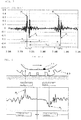
- the positions of leading end point and trailing end point of tire footprint can be identified from the positions of peaks appearing in the time-series waveform of tire vibration.
- an excessive input impact
- a conspicuous peak appears in the time-series waveform.
- the positions of leading end point and trailing end point can sometimes be estimated incorrectly.
- Patent Document 1 A solution to this problem as disclosed in Patent Document 1 is the installation of an acceleration sensor for monitoring on the suspension. And when the value of acceleration detected by the acceleration sensor for monitoring exceeds a predetermined threshold value, it is determined that there has been an excessive input (hereinafter referred to as large input) to the tire, and the estimation of a road surface condition is canceled.
- large input an excessive input
- Patent Document 1 Japanese Unexamined Patent Application Publication No. 2011-242303
- Patent Document 1 requires the installation of an acceleration sensor for monitoring on the suspension (unsprung).
- the present invention has been made in view of the above-described problem, and an object of the invention is to provide a method for estimating a road surface condition by accurately determining whether or not there has been any large input to the tire, without an increase in the number of sensors.
- the present invention provides a method for estimating a road surface condition under a tire in motion from a time-series waveform of tire vibration detected by a vibration detecting means.
- the method includes estimating positions of a leading end point and a trailing end point of tire contact patch from peak positions appearing in the time-series waveform, calculating cne or more of contact time, extra-contact time, and revolution time, which is the time for one revolution of the tire, from the estimated positions of leading end point and trailing end point, and determining whether or not the estimated positions of leading end point and trailing end point are equal to the actual positions of leading end point and trailing end point, based on one or more of the calculated contact time, extra-contact time, and revolution time.
- the estimation of a road surface condition is not performed when it is determined that one or both of the positions of leading end point and trailing end point estimated in the above step of estimating are not equal to the actual positions of leading end point and trailing end point.
- the leading end point refers to the time, or the position on the tire circumference, at which the circumferential position of the tire where the vibration detecting means is installed (hereinafter referred to as measuring point) engages with the road surface, on the time-series waveform of tire vibration, and the trailing end point the time, or the position on the tire circumference, at which the measuring point disengages from the road surface.
- FIG. 1 is a functional block diagram of a road surface condition estimating apparatus 10 according to an embodiment of the present invention.
- the road surface condition estimating apparatus 10 includes an acceleration sensor 11 as a vibration detecting means, a wheel speed sensor 12 as a wheel speed detecting means, a vibration waveform detecting means 13, a leading and trailing position estimating means 14, a contact time and revolution time calculating means 15, a determining means 16, a storage means 17, and a road surface condition estimating means 18.
- the respective means cited above namely, the vibration waveform detecting means 13 to the determining means 16 and the road surface condition estimating means 18, may be constituted by computer software, for instance, and the storage means 17 by a RAM and ROM, and they are all incorporated into a vehicle control unit installed on a vehicle body.
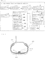
- the acceleration sensor 11, as shown in FIG. 2 is disposed nearly at the midportion of the inner liner 21 on the tire air chamber 22 side of the tire 20. And the acceleration sensor 11 detects the vibration inputted to the tread 23 of the tire 20 from the road surface as acceleration.
- the position of the acceleration sensor 11 (to be exact, the position on the surface of the tread 23 radially outside of the acceleration sensor 11) is referred to as the measuring point.
- the output of the acceleration sensor 11 is sent to a vehicle control unit installed on the vehicle body by a transmitter 11F, for instance.
- the wheel speed sensor 12 detects the revolution speed of the wheel (hereinafter referred to as wheel speed).
- the wheel speed sensor 12 is comprised, for instance, of a rotor formed with gear teeth on its periphery and rotating together with the wheel, a yoke constituting a magnetic circuit in association with the rotor, and a coil for detecting changes in magnetic flux of the magnetic circuit.
- a wheel speed sensor of a known electromagnetic induction type or the like may be used for detecting the angle of rotation of the wheel.
- the vibration waveform detecting means 13 detects a time-series waveform of vibration inputted to the tire 20 in motion, which is tire vibration on a time-series plot, outputted by the acceleration sensor 11.
- the peak (a positive peak here) appearing first in the time-series waveform of vibration is the leading end point P f , which is the peak occurring when the measuring point engages with the road surface.
- the peak (a negative peak here) appearing next is the trailing end point P k , which is the peak occurring when the measuring point disengages from the road surface.
- the leading and trailing position estimating means 14 detects two peaks appearing first, one positive and one negative, from the time-series waveform of vibration, thereby estimating the times of appearance of these peaks to be the position t 11 of the leading end point P f and the position t 12 of the trailing end point P k , respectively. Also, the leading and trailing position estimating means 14 estimates the times of the two peaks, one positive and one negative, appearing next to be the position t 21 of the next leading end point P f and the position t 22 of the next trailing end point P k , respectively.
- the contact time and revolution time calculating means 15 calculates the contact time T a , which is the space of time when the measuring point is in contact with the road surface, from the difference between the position t 11 of the leading end point P f and the position t 12 of the trailing end point P k .
- the contact time and revolution time calculating means 15 calculates the revolution time T ab , which is the time taken by one revolution of the tire 20, from the difference between the position t 12 of the first trailing end point P k and the position t 22 cf the next trailing end point P k . Note that the difference between the position t 12 of the trailing end point P k and the position t 21 of the next leading end point P f is the extra-contact time T b .
- T a t 12 - t 11
- T c t 21 - t 12
- T ab t 22 - t 12
- the revolution time T ab may be calculated from the difference between the position t 11 of the leading end point P f and the position t 21 of the next leading end point P f .
- the determining means 16 includes a contact time ratio calculating unit 161, a comparison determining unit 162, and a cancel signal outputting unit 163.
- the contact time ratio calculating unit 161 calculates the contact time ratio R, which is the ratio between the contact time T a and revolution time T ab calculated by the contact time and revolution time calculating means 15.
- the comparison determining unit 162 determines whether or not the position t 11 of the leading end point P f and the positions t 12 and t 22 of the trailing end point P k estimated by the leading and trailing position estimating means 14 are all equal to the actual positions of leading end point and trailing end point.
- the contact time ratio R is in the predetermined contact time ratio range [from R1 to R2].
- the contact time ratio R is in the contract time ratio range (R1 ⁇ R ⁇ R2), it is determined that t 11 , t 12 , and t 22 estimated by the leading and trailing position estimating means 14 are all equal to the actual positions of leading end point and trailing end point (normal positions).
- the cancel signal outputting unit 163 outputs a cancel signal, which is a command signal to cancel the operation of road surface estimation, to the road surface condition estimating means 18 when the comparison determining unit 162 has determined that the estimation was incorrect, that is, there was a failure in estimating the position of the leading end point P f and the position of the trailing end point P k correctly.
- the storage means 17 stores a map 17M showing a relationship between predetermined road surface conditions and calculated values of vibration level.
- the road surface condition estimating means 18 includes a waveform domain dividing unit 181, a domain signal extracting unit 182, a frequency analyzing unit 183, a vibration level calculating unit 184, and a road surface condition estimating unit 185.
- the read surface condition estimating means 18 estimates a road surface condition only when it is determined that the positions of leading end point and trailing end point estimated by the leading and trailing position estimating means 14 are equal to the actual positions of leading end point and trailing end point. And it cancels the estimation of a road surface condition when a cancel signal is outputted from the cancel signal outputting unit 163.
- the waveform domain dividing unit 181 extracts a vibration waveform for a single revolution of the tire, using the position of the leading end point P f or the trailing end point P k estimated by the leading and trailing position estimating means 14 and the revolution speed of the tire 20 detected by the wheel speed sensor 12. At the same time, it divides the vibration waveform into the data of two domains, namely, the leading end domain and the trailing end domain as shown in FIG. 4 .
- the domain signal extracting unit 182 extracts the time-series waveforms of vibration level in the respective domains.
- the frequency analyzing unit 183 which is constituted by a frequency analyzing means such as an FFT analyzer, generates frequency spectrums by performing a frequency analysis on the extracted time-series waveforms of vibration level, respectively.
- the vibration level calculating unit 184 calculates the leading end vibration level V f , which is the vibration level in a predetermined frequency band of the frequency spectrum in the leading end domain, and the trailing end vibration level V k , which is the vibration level in a predetermined frequency band of the frequency spectrum in the trailing end domain. At the same time, it calculates a calculated value S of the vibration levels, using these vibration levels.
- the calculated value S may be the ratio of the leading end vibration level V f to the trailing end vibration level V k , fcr instance.
- the road surface condition estimating unit 185 estimates the condition of the road surface under the traveling vehicle, based on the map 17M, stored in the storage means 17, showing the relationship between the predetermined road surface conditions and the calculated value S of the vibration levels and the data of the calculated value S of the vibration levels calculated by the vibration level calculating unit 184.
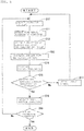
- step S10 the circumferential vibration of the tire 20 in motion is detected by the acceleration sensor 11 (step S10) . And the output is sent to the vibration waveform detecting means 13, where the time-series waveform of vibration, which is the vibration waveform in the tire circumferential direction on a time-series plot, is determined (step S11).
- step S12 From the time-series waveform of vibration as shown in FIG. 3 , the position t 11 of the leading end point P f appearing first, the position t 12 of the trailing end point P k appearing first, and the position t 22 of the trailing end point P k appearing next are estimated by the leading and trailing position estimating means 14 (step S12).
- the contact time T a and the revolution time T ab are calculated by the contact time and revolution time calculating means 15 (step S13).
- step S14 After the contact time ratio R, which is the ratio between the contact time T a and the revolution time T ab , is calculated (step S14), it is determined by the determining means 16 whether or not the contact time ratio R is in the predetermined contact time ratio range [from R1 to R2]. At the same time, a leading and trailing position determination is performed, in which it is determined whether or not the t 11 , t 12 , and t 22 detected in step S12 are all equal to the actual positions of the leading end point P f and trailing end point P k (step S15).
- the revolution time T ab calculated will be shorter than the actual revolution time T ab .
- the contact time t a will be shorter than the actual contact time T a .
- a range of contact time ratio [from R1 to R2] is predetermined for the contact time ratio R, and the R is compared against the lower limit value R1 and the upper limit value R2 of the contact time ratio range. Then by determining whether or not the contact time ratio R is in the predetermined contact time ratio range, a leading and trailing position determination can be performed, in which it is determined whether or not the position t 11 of the leading end point P f and the positions t 12 and t 22 of the trailing end point P k estimated by the leading and trailing position estimating means 14 are equal to the actual positions of leading end point and trailing end point.
- step S15 When the result of leading and trailing position determination in step S15 is "normal positions", the procedure goes to step S16, where an estimation of a road surface condition is performed using the time-series waveform of vibration level.
- step S17 when the result of leading and trailing position determination is "incorrect estimation”, a cancel signal is outputted to the road surface condition estimating means 18 (step S17), and the procedure goes back to step S10, where the detection of the circumferential vibration of the tire 20 in motion is continued.
- step S16 it is determined whether the operation of estimating a road surface condition has been completed (step S18). And if the operation of estimation is to be continued, the procedure returns to step S10, where the detection of the circumferential vibration cf the tire 2C in motion is continued. It it is not to be continued, this operation is brought to an end.
- step S16 The method for estimating a road surface condition in step S16 is as described below:
- the extracted time-series waveforms of vibration level are subjected to a frequency analysis, respectively. And from the frequency spectrums of the two domains resulting from the frequency analysis, the vibration levels V f and V k in predetermined frequency bands are calculated. Then a calculated value S is computed from the vibration levels V f and V k .
- the condition of the road surface under the traveling vehicle is estimated from the calculated value S and the map 17M showing the relationship between the predetermined road surface conditions and the calculated value S f of vibration levels.
- the vibration level V f in the frequency band of 8 to 10 kHz is calculated from the frequency spectrum of the leading end domain
- the vibration level V k in the frequency band of 1 to 3 kHz is calculated from the frequency spectrum cf the trailing end domain.
- an acceleration sensor 11 is disposed on the tire 20 to detect the circumferential vibration of the tire 20 in motion.
- the positions of the leading end point P f and trailing end point P k of tire contact patch are estimated from the peak positions appearing in the time-variable waveform of the vibration.
- the contact time T a , extra-contact time T b , and revolution time T ab of the tire 20 are calculated from the estimated positions of the leading end point P f and trailing end point P k .
- a leading and trailing position determination is performed, in which it is determined whether or not the estimated positions of the leading end point P f and trailing end point P k are equal to the actual positions of leading end point and trailing end point. And if the result of determination is "incorrect estimation", the estimation of a road surface condition is not performed. Accordingly, it is possible to accurately determine whether cr not there has been any excessive input to the tire without an increase in the number of sensors. Thus, the accuracy in the estimation of a road surface condition can be improved.
- the arrangement may also be such that when the contact time or the contact length estimated from the contact time is outside the predetermined range of contact length, it is determined that one or both of the estimated positions of leading end point and trailing end point are not equal to the actual positions of leading end point and trailing end point.
- the arrangement may be such that when the revolution time or the revolution length estimated from the revolution time is outside the predetermined range of revolution length, it is determined that one or both of the estimated positions of leading end point and trailing end point are not equal to the actual positions of leading end point and trailing end point.
- the arrangement may be such that the contact time ratio, which is the ratio between the contact time and the revolution time, is calculated and when the calculated contact time ratio is outside the predetermined range of contact time ratio, it is determined that one or both of the estimated positions of leading end point and trailing end point are not equal to the actual positions of leading end point and trailing end point.
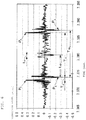
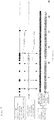
- FIG. 7 is a diagram comparing the results of incorrect estimation as determined by the leading and trailing position determination of the present invention with the results of large input detection by the monitoring acceleration sensor as described in the afore-mentioned Patent Document 1.
- the leading and trailing position determination of the present invention displays a determination accuracy equal to or better than that of the large input detection described in Patent Document 1.
- the invention provides the determination with accuracy whether or not the positions of leading end point and trailing end point estimated from the vibration waveform are equal to the actual positions of leading end point and trailing end point.
- an acceleration sensor 11 is disposed on the tire air chamber 21 side of the inner liner 21 of the tire 20 to detect the circumferential vibration of the tire.
- the arrangement may be such that the acceleration sensor is attached on the knuckle to detect the fore-aft vibration of the tire.
- the positions of the leading end point P f and trailing end point P k and a road surface condition are estimated using the circumferential vibration of the tire detected by the acceleration sensor 11.
- the axial acceleration or radial acceleration of the tire may be used instead.
- a differential acceleration derived by differentiating the detected radial acceleration of the tire is used, which will enable a more accurate estimation of the positions of the leading end point F f and trailing end point P k .
- a road surface condition under a traveling vehicle is estimated based on a calculated value S of the leading-end vibration level V f and traiing-end vibration level V k derived from the time-series waveform of tire vibration detected by the acceleration sensor 11 and the map 17M showing the relationship between the predetermined road surface conditions and the calculated value S f .
- the invention is applicable to an apparatus for estimating a road surface condition using a time-variable waveform of vibration of the tire in motion detected by a vibration detecting means as disclosed in Patent Document 1.
- the vibration waveform is divided into the leading end domain and the trailing end domain, using the output of the wheel speed sensor 12.
- the vibration waveform may be divided into the leading end domain and the trailing end domain by converting the time-series waveform of the vibration waveform into the vibration waveforms at predetermined positions of the tire from the motional radius and the revolution time of the tire. Then the wheel speed sensor 12 may be omitted.
- the present invention may be applicable to a road surface condition estimating apparatus having no wheel speed sensor 12 as a constituent element.
- the leading and trailing position determination is performed using the contact time ratio R.
- the leading and trailing position determination may be performed using any one of the contact time, the extra-contact time, and the revolution time.
- the contact length and the revolution length may be used in the place of the contact time and the revolution time. Then there will be no dependence on the wheel speed. This will further improve the accuracy of leading and trailing position determination.
- the contact time or the contact length it is determined to be “incorrect estimation” when the contact time or the contact length is outside the predetermined range of contact length.
- the revolution time or the revolution length it is determined to be “incorrect estimation” when the revolution time or the revolution length is outside the predetermined range of revolution length.
Landscapes
- Engineering & Computer Science (AREA)
- Mechanical Engineering (AREA)
- Physics & Mathematics (AREA)
- Transportation (AREA)
- Analytical Chemistry (AREA)
- Health & Medical Sciences (AREA)
- Life Sciences & Earth Sciences (AREA)
- Chemical & Material Sciences (AREA)
- Acoustics & Sound (AREA)
- Biochemistry (AREA)
- General Health & Medical Sciences (AREA)
- General Physics & Mathematics (AREA)
- Immunology (AREA)
- Pathology (AREA)
- Control Of Driving Devices And Active Controlling Of Vehicle (AREA)
- Tires In General (AREA)
- Length Measuring Devices With Unspecified Measuring Means (AREA)
Abstract
Description
- The present invention relates to a method for estimating a road surface condition under a traveling vehicle.
- To enhance the travel stability of a vehicle, it is desired that the road surface condition under a traveling vehicle is estimated with accuracy and the data thus obtained is fed back to vehicle control. If the road surface condition can be estimated in time, then it will be possible to operate such advanced control as ABS (antilock braking system) braking before taking any danger avoidance action such as braking, accelerating, or steering. With such facility, there will be a marked boost in the safety of vehicular operation.
- In a proposed method for estimating a road surface condition (see
Patent Document 1, for instance), a time-series waveform of vibration of the tire tread cf a traveling vehicle is detected by an acceleration sensor installed on the inner liner of the tire. The time-series waveform is then subjected to a frequency analysis by extracting the time-series waveform of a demain including a leading end point of tire contact patch (footprint) and the time-series waveform of a domain including a trailing end point. From frequency spectrums thus derived, a band value Pfi of the leading end domain and a band value Pkj of the trailing end domain, which are the vibration levels of the plurality of frequency bands, are calculated respectively. And a road surface condition is estimated from these band values Pfi and Pkj. - It should be noted that the positions of leading end point and trailing end point of tire footprint can be identified from the positions of peaks appearing in the time-series waveform of tire vibration. However, when the tire receives an excessive input (impact), such as when going over a bump or a curb, a conspicuous peak appears in the time-series waveform. In such cases, the positions of leading end point and trailing end point can sometimes be estimated incorrectly.
- A solution to this problem as disclosed in
Patent Document 1 is the installation of an acceleration sensor for monitoring on the suspension. And when the value of acceleration detected by the acceleration sensor for monitoring exceeds a predetermined threshold value, it is determined that there has been an excessive input (hereinafter referred to as large input) to the tire, and the estimation of a road surface condition is canceled. - Patent Document 1:
Japanese Unexamined Patent Application Publication No. 2011-242303 - However, the method disclosed in
Patent Document 1 requires the installation of an acceleration sensor for monitoring on the suspension (unsprung). - The present invention has been made in view of the above-described problem, and an object of the invention is to provide a method for estimating a road surface condition by accurately determining whether or not there has been any large input to the tire, without an increase in the number of sensors.
- The present invention provides a method for estimating a road surface condition under a tire in motion from a time-series waveform of tire vibration detected by a vibration detecting means. The method includes estimating positions of a leading end point and a trailing end point of tire contact patch from peak positions appearing in the time-series waveform, calculating cne or more of contact time, extra-contact time, and revolution time, which is the time for one revolution of the tire, from the estimated positions of leading end point and trailing end point, and determining whether or not the estimated positions of leading end point and trailing end point are equal to the actual positions of leading end point and trailing end point, based on one or more of the calculated contact time, extra-contact time, and revolution time. And the estimation of a road surface condition is not performed when it is determined that one or both of the positions of leading end point and trailing end point estimated in the above step of estimating are not equal to the actual positions of leading end point and trailing end point.
- Here, the leading end point refers to the time, or the position on the tire circumference, at which the circumferential position of the tire where the vibration detecting means is installed (hereinafter referred to as measuring point) engages with the road surface, on the time-series waveform of tire vibration, and the trailing end point the time, or the position on the tire circumference, at which the measuring point disengages from the road surface.
- By implementing the above-described arrangement, it is possible to avoid incorrect estimation of a large peak appearing in the time-series waveform of tire vibration when there has been a large input to the tire, as the peak at the leading end point or the peak at the trailing end point. Therefore the road surface condition can be estimated with accuracy.
- It is to be understood that the foregoing summary of the invention does not necessarily recite all the features essential to the invention, and subcombinations of all these features are intended to be included in the invention.
-
-
FIG. 1 is a diagram showing a configuration of a road surface condition estimating apparatus in accordance with the present invention. -
FIG. 2 is an illustration showing an example of disposition of an acceleration sensor. -
FIG. 3 is a diagram showing an example of a time-series waveform of vibration. -
FIG. 4 is a diagram showing a leading end pint and a trailing end point. -
FIG. 5 is a flowchart showing a method for estimating a road surface condition according to an embodiment. -
FIG. 6 is a diagram showing an example of a time-series waveform of vibration when there has been a large input to the tire. -
FIG. 7 is a diagram for explaining the accuracy of estimation of a large input in accordance with the present invention. -
FIG. 1 is a functional block diagram of a road surfacecondition estimating apparatus 10 according to an embodiment of the present invention. - The road surface
condition estimating apparatus 10 includes anacceleration sensor 11 as a vibration detecting means, awheel speed sensor 12 as a wheel speed detecting means, a vibration waveform detecting means 13, a leading and trailing position estimating means 14, a contact time and revolutiontime calculating means 15, a determiningmeans 16, a storage means 17, and a road surface condition estimating means 18. - The respective means cited above, namely, the vibration waveform detecting means 13 to the determining
means 16 and the road surface condition estimating means 18, may be constituted by computer software, for instance, and the storage means 17 by a RAM and ROM, and they are all incorporated into a vehicle control unit installed on a vehicle body. - The
acceleration sensor 11, as shown inFIG. 2 , is disposed nearly at the midportion of theinner liner 21 on thetire air chamber 22 side of thetire 20. And theacceleration sensor 11 detects the vibration inputted to thetread 23 of thetire 20 from the road surface as acceleration. In the present example, theacceleration sensor 11, which is so disposed that the detecting direction thereof is the tire circumferential direction, detects the circumferential vibration of the tire inputted from the road surface. Hereinafter, the position of the acceleration sensor 11 (to be exact, the position on the surface of thetread 23 radially outside of the acceleration sensor 11) is referred to as the measuring point. It is to be noted that the output of theacceleration sensor 11 is sent to a vehicle control unit installed on the vehicle body by a transmitter 11F, for instance. - The
wheel speed sensor 12 detects the revolution speed of the wheel (hereinafter referred to as wheel speed). Thewheel speed sensor 12 is comprised, for instance, of a rotor formed with gear teeth on its periphery and rotating together with the wheel, a yoke constituting a magnetic circuit in association with the rotor, and a coil for detecting changes in magnetic flux of the magnetic circuit. A wheel speed sensor of a known electromagnetic induction type or the like may be used for detecting the angle of rotation of the wheel. - The vibration waveform detecting means 13 detects a time-series waveform of vibration inputted to the
tire 20 in motion, which is tire vibration on a time-series plot, outputted by theacceleration sensor 11. - As shown in
FIG. 3 , there appear two conspicuous peaks, one positive and one negative, in every revolution of the tire in the time-series waveform of vibration. - The peak (a positive peak here) appearing first in the time-series waveform of vibration is the leading end point Pf, which is the peak occurring when the measuring point engages with the road surface. The peak (a negative peak here) appearing next is the trailing end point Pk, which is the peak occurring when the measuring point disengages from the road surface.
- The leading and trailing position estimating means 14 detects two peaks appearing first, one positive and one negative, from the time-series waveform of vibration, thereby estimating the times of appearance of these peaks to be the position t11 of the leading end point Pf and the position t12 of the trailing end point Pk, respectively. Also, the leading and trailing position estimating means 14 estimates the times of the two peaks, one positive and one negative, appearing next to be the position t21 of the next leading end point Pf and the position t22 of the next trailing end point Pk, respectively.
- The contact time and revolution time calculating means 15 calculates the contact time Ta, which is the space of time when the measuring point is in contact with the road surface, from the difference between the position t11 of the leading end point Pf and the position t12 of the trailing end point Pk. At the same time, the contact time and revolution
time calculating means 15 calculates the revolution time Tab, which is the time taken by one revolution of thetire 20, from the difference between the position t12 of the first trailing end point Pk and the position t22 cf the next trailing end point Pk. Note that the difference between the position t12 of the trailing end point Pk and the position t21 of the next leading end point Pf is the extra-contact time Tb. - Accordingly, Ta = t12 - t11, Tc = t21 - t12, Tab = t22 - t12
- Also, the revolution time Tab may be calculated from the difference between the position t11 of the leading end point Pf and the position t21 of the next leading end point Pf.
- The determining means 16 includes a contact time
ratio calculating unit 161, acomparison determining unit 162, and a cancelsignal outputting unit 163. - The contact time
ratio calculating unit 161 calculates the contact time ratio R, which is the ratio between the contact time Ta and revolution time Tab calculated by the contact time and revolution time calculating means 15. - The
comparison determining unit 162 determines whether or not the position t11 of the leading end point Pf and the positions t12 and t22 of the trailing end point Pk estimated by the leading and trailing position estimating means 14 are all equal to the actual positions of leading end point and trailing end point. - More specifically, it is determined whether or not the contact time ratio R is in the predetermined contact time ratio range [from R1 to R2]. When the contact time ratio R is in the contract time ratio range (R1 ≦ R ≦ R2), it is determined that t11, t12, and t22 estimated by the leading and trailing position estimating means 14 are all equal to the actual positions of leading end point and trailing end point (normal positions).
- On the other hand, when the contact time ratio R is not in the contact time ratio range (R < R1 or R > R2), it is determined that one, two, or all of the estimated position t11 of the leading end point Pf and positions t12 and t22 of the trailing end point Pk are not equal to the actual positions of leading end point and trailing end point (incorrect estimation).
- The cancel
signal outputting unit 163 outputs a cancel signal, which is a command signal to cancel the operation of road surface estimation, to the road surface condition estimating means 18 when thecomparison determining unit 162 has determined that the estimation was incorrect, that is, there was a failure in estimating the position of the leading end point Pf and the position of the trailing end point Pk correctly. - The storage means 17 stores a
map 17M showing a relationship between predetermined road surface conditions and calculated values of vibration level. - The road surface condition estimating means 18 includes a waveform
domain dividing unit 181, a domainsignal extracting unit 182, afrequency analyzing unit 183, a vibrationlevel calculating unit 184, and a road surfacecondition estimating unit 185. The read surface condition estimating means 18 estimates a road surface condition only when it is determined that the positions of leading end point and trailing end point estimated by the leading and trailing position estimating means 14 are equal to the actual positions of leading end point and trailing end point. And it cancels the estimation of a road surface condition when a cancel signal is outputted from the cancelsignal outputting unit 163. - The waveform
domain dividing unit 181 extracts a vibration waveform for a single revolution of the tire, using the position of the leading end point Pf or the trailing end point Pk estimated by the leading and trailing position estimating means 14 and the revolution speed of thetire 20 detected by thewheel speed sensor 12. At the same time, it divides the vibration waveform into the data of two domains, namely, the leading end domain and the trailing end domain as shown inFIG. 4 . - The domain
signal extracting unit 182 extracts the time-series waveforms of vibration level in the respective domains. - The
frequency analyzing unit 183, which is constituted by a frequency analyzing means such as an FFT analyzer, generates frequency spectrums by performing a frequency analysis on the extracted time-series waveforms of vibration level, respectively. - The vibration
level calculating unit 184 calculates the leading end vibration level Vf, which is the vibration level in a predetermined frequency band of the frequency spectrum in the leading end domain, and the trailing end vibration level Vk, which is the vibration level in a predetermined frequency band of the frequency spectrum in the trailing end domain. At the same time, it calculates a calculated value S of the vibration levels, using these vibration levels. The calculated value S may be the ratio of the leading end vibration level Vf to the trailing end vibration level Vk, fcr instance. - The road surface
condition estimating unit 185 estimates the condition of the road surface under the traveling vehicle, based on themap 17M, stored in the storage means 17, showing the relationship between the predetermined road surface conditions and the calculated value S of the vibration levels and the data of the calculated value S of the vibration levels calculated by the vibrationlevel calculating unit 184. - Now, a description is given of a method for estimating a road surface condition according to this embodiment, with reference to the flowchart of
FIG. 5 . - Firstly, the circumferential vibration of the
tire 20 in motion is detected by the acceleration sensor 11 (step S10) . And the output is sent to the vibrationwaveform detecting means 13, where the time-series waveform of vibration, which is the vibration waveform in the tire circumferential direction on a time-series plot, is determined (step S11). - Next, from the time-series waveform of vibration as shown in
FIG. 3 , the position t11 of the leading end point Pf appearing first, the position t12 of the trailing end point Pk appearing first, and the position t22 of the trailing end point Pk appearing next are estimated by the leading and trailing position estimating means 14 (step S12). - Then, using the t11, t12, and t22 detected in the step S12, the contact time Ta and the revolution time Tab are calculated by the contact time and revolution time calculating means 15 (step S13).
- Next, after the contact time ratio R, which is the ratio between the contact time Ta and the revolution time Tab, is calculated (step S14), it is determined by the determining means 16 whether or not the contact time ratio R is in the predetermined contact time ratio range [from R1 to R2]. At the same time, a leading and trailing position determination is performed, in which it is determined whether or not the t11, t12, and t22 detected in step S12 are all equal to the actual positions of the leading end point Pf and trailing end point Pk (step S15).
- It is to be noted that when the tire receives an excessive input (hereinafter referred to as large input), such as when going over a bump or a curb, a conspicuous peak appears in the time-series waveform as shown in
FIG. 6 . In such cases, the positions of leading end point Pf and trailing end point Pk can sometimes be estimated incorrectly. - For example, if the position of a large input as shown in the figure is estimated to be the position of the trailing end point Pk occurring next, then the revolution time Tab calculated will be shorter than the actual revolution time Tab.
- Also, if the position of the large input is estimated to be the position of the leading end point Pf occurring next, then the contact time ta will be shorter than the actual contact time Ta.
- Hence, a range of contact time ratio [from R1 to R2] is predetermined for the contact time ratio R, and the R is compared against the lower limit value R1 and the upper limit value R2 of the contact time ratio range. Then by determining whether or not the contact time ratio R is in the predetermined contact time ratio range, a leading and trailing position determination can be performed, in which it is determined whether or not the position t11 of the leading end point Pf and the positions t12 and t22 of the trailing end point Pk estimated by the leading and trailing position estimating means 14 are equal to the actual positions of leading end point and trailing end point.
- When the result of leading and trailing position determination in step S15 is "normal positions", the procedure goes to step S16, where an estimation of a road surface condition is performed using the time-series waveform of vibration level.
- On the other hand, when the result of leading and trailing position determination is "incorrect estimation", a cancel signal is outputted to the road surface condition estimating means 18 (step S17), and the procedure goes back to step S10, where the detection of the circumferential vibration of the
tire 20 in motion is continued. - When a cancel signal is outputted, the estimation of a road surface condition is canceled.
- Note that at the end of step S16, it is determined whether the operation of estimating a road surface condition has been completed (step S18). And if the operation of estimation is to be continued, the procedure returns to step S10, where the detection of the circumferential vibration cf the tire 2C in motion is continued. It it is not to be continued, this operation is brought to an end.
- The method for estimating a road surface condition in step S16 is as described below:
- Firstly, a vibration waveform for one tire revolution is extracted from the time-series waveform of vibration inputted to the
tire 20, which is outputted by theacceleration sensor 11. The extracted vibration waveform is divided into data of two domains, namely, the leading end domain and the trailing end domain. And then the time-series waveforms of vibration level in the two domains are extracted, respectively. - Next, the extracted time-series waveforms of vibration level are subjected to a frequency analysis, respectively. And from the frequency spectrums of the two domains resulting from the frequency analysis, the vibration levels Vf and Vk in predetermined frequency bands are calculated. Then a calculated value S is computed from the vibration levels Vf and Vk.
- Then the condition of the road surface under the traveling vehicle is estimated from the calculated value S and the
map 17M showing the relationship between the predetermined road surface conditions and the calculated value Sf of vibration levels. - More specifically, the vibration level Vf in the frequency band of 8 to 10 kHz is calculated from the frequency spectrum of the leading end domain, and the vibration level Vk in the frequency band of 1 to 3 kHz is calculated from the frequency spectrum cf the trailing end domain. And the road surface condition is estimated by determining to which of the calculated value Sf of the road surface the calculated value S = Vf/Vk is closer.
- According to the present embodiment, therefore, an
acceleration sensor 11 is disposed on thetire 20 to detect the circumferential vibration of thetire 20 in motion. The positions of the leading end point Pf and trailing end point Pk of tire contact patch are estimated from the peak positions appearing in the time-variable waveform of the vibration. At the same time, the contact time Ta, extra-contact time Tb, and revolution time Tab of thetire 20 are calculated from the estimated positions of the leading end point Pf and trailing end point Pk. Then using one or more of the calculated data, a leading and trailing position determination is performed, in which it is determined whether or not the estimated positions of the leading end point Pf and trailing end point Pk are equal to the actual positions of leading end point and trailing end point. And if the result of determination is "incorrect estimation", the estimation of a road surface condition is not performed. Accordingly, it is possible to accurately determine whether cr not there has been any excessive input to the tire without an increase in the number of sensors. Thus, the accuracy in the estimation of a road surface condition can be improved. - In step S15, the arrangement may also be such that when the contact time or the contact length estimated from the contact time is outside the predetermined range of contact length, it is determined that one or both of the estimated positions of leading end point and trailing end point are not equal to the actual positions of leading end point and trailing end point.
- Also, in step S15, the arrangement may be such that when the revolution time or the revolution length estimated from the revolution time is outside the predetermined range of revolution length, it is determined that one or both of the estimated positions of leading end point and trailing end point are not equal to the actual positions of leading end point and trailing end point.
- This makes it possible to determine whether or not the positions of leading end point and trailing end point estimated using a simple method are equal to the actual positions of leading end point and trailing end point.
- Also, in step S15, the arrangement may be such that the contact time ratio, which is the ratio between the contact time and the revolution time, is calculated and when the calculated contact time ratio is outside the predetermined range of contact time ratio, it is determined that one or both of the estimated positions of leading end point and trailing end point are not equal to the actual positions of leading end point and trailing end point.
- As a result, it is possible to determine, without using the wheel speed, whether or not the estimated positions of leading end point and trailing end point are equal to the actual positions of leading end point and trailing end point. This can further improve the accuracy of the estimation of a road surface condition.
-
FIG. 7 is a diagram comparing the results of incorrect estimation as determined by the leading and trailing position determination of the present invention with the results of large input detection by the monitoring acceleration sensor as described in the afore-mentionedPatent Document 1. As is clear from the diagram, the leading and trailing position determination of the present invention displays a determination accuracy equal to or better than that of the large input detection described inPatent Document 1. - Thus, it has been confirmed that even when there is a large input, the invention provides the determination with accuracy whether or not the positions of leading end point and trailing end point estimated from the vibration waveform are equal to the actual positions of leading end point and trailing end point.
- Thus far, the invention has been described with reference to specific embodiments thereof and an experimental example. However, the technical scope of this invention is net to be considered as limited to those embodiments. It will be evident to those skilled in the art that various modifications and changes may be made thereto without departing from the broader spirit and scope of the invention. It will also be evident from the scope of the appended claims that all such modifications are intended to be included within the technical scope of this invention.
- For example, in the foregoing embodiment, an
acceleration sensor 11 is disposed on thetire air chamber 21 side of theinner liner 21 of thetire 20 to detect the circumferential vibration of the tire. However, the arrangement may be such that the acceleration sensor is attached on the knuckle to detect the fore-aft vibration of the tire. - Also, in the foregoing embodiment, the positions of the leading end point Pf and trailing end point Pk and a road surface condition are estimated using the circumferential vibration of the tire detected by the
acceleration sensor 11. However, the axial acceleration or radial acceleration of the tire may be used instead. Yet, when the radial acceleration of the tire is to be used, it is preferable that a differential acceleration derived by differentiating the detected radial acceleration of the tire is used, which will enable a more accurate estimation of the positions of the leading end point Ff and trailing end point Pk. - Also, in the foregoing embodiment, a road surface condition under a traveling vehicle is estimated based on a calculated value S of the leading-end vibration level Vf and traiing-end vibration level Vk derived from the time-series waveform of tire vibration detected by the
acceleration sensor 11 and themap 17M showing the relationship between the predetermined road surface conditions and the calculated value Sf. But this is not a limitation of the present invention. For example, the invention is applicable to an apparatus for estimating a road surface condition using a time-variable waveform of vibration of the tire in motion detected by a vibration detecting means as disclosed inPatent Document 1. - Also, in the foregoing embodiment, the vibration waveform is divided into the leading end domain and the trailing end domain, using the output of the
wheel speed sensor 12. However, the vibration waveform may be divided into the leading end domain and the trailing end domain by converting the time-series waveform of the vibration waveform into the vibration waveforms at predetermined positions of the tire from the motional radius and the revolution time of the tire. Then thewheel speed sensor 12 may be omitted. - Accordingly, the present invention may be applicable to a road surface condition estimating apparatus having no
wheel speed sensor 12 as a constituent element. - Also, in the foregoing embodiment, the leading and trailing position determination is performed using the contact time ratio R. However, the leading and trailing position determination may be performed using any one of the contact time, the extra-contact time, and the revolution time.
- Also, the contact length and the revolution length may be used in the place of the contact time and the revolution time. Then there will be no dependence on the wheel speed. This will further improve the accuracy of leading and trailing position determination.
- For example, when the contact time or the contact length is used, it is determined to be "incorrect estimation" when the contact time or the contact length is outside the predetermined range of contact length. Also, when the revolution time or the revolution length is used, it is determined to be "incorrect estimation" when the revolution time or the revolution length is outside the predetermined range of revolution length.
- It should be noted that in the foregoing embodiment, it is determined whether or not one or both of the positions of leading end point and trailing end point estimated from the contact time Ta and the revolution time Tab are equal to the actual positions of leading end point and trailing end point. However, since the extra-contact time Tb is the difference between the revolution time Tab and the contact time Ta, it goes without saying that it can be determined whether or not one or both of the positions of leading end point and trailing end point estimated from the contact time Ta and the extra-contact time Tb or from the extra-contact time Tb and the revolution time Tab are equal to the actual positions of leading end point and trailing end point.
-
- 10
- road surface condition estimating apparatus
- 11
- acceleration sensor
- 12
- wheel speed sensor
- 13
- vibration waveform detecting means
- 14
- leading and trailing position estimating means
- 15
- contact time and revolution time calculating means
- 16
- determining means
- 161
- contact time ratio calculating unit
- 162
- comparison determining unit
- 163
- cancel signal outputting unit
- 17
- storage means
- 18
- road surface condition estimating means
- 181
- waveform domain dividing unit
- 182
- domain signal extracting unit
- 183
- frequency analyzing unit
- 184
- vibration level calculating unit
- 185
- road surface condition estimating unit
- 20
- tire
- 21
- inner liner
- 22
- tire air chamber
- 23
- tread
Claims (4)
- A method for estimating a road surface condition under a tire in motion from a time-series waveform of tire vibration detected by a vibration detecting means, the method comprising:estimating positions of leading end point and trailing end point of tire contact patch from peak positions appearing in the time-series waveform;calculating one or more of contact time, extra-contact time, and revolution time, which is the time for one revolution of the tire, from the estimated positions of leading end point and trailing end point; anddetermining whether or not the estimated positions of leading end point and trailing end point are equal to the actual positions of leading end point and trailing end point, based on one or more of the calculated contact time, extra-contact time, and revolution time,wherein the estimation of a road surface condition is not performed when it is determined that one or both of the positions of leading end point and trailing end point estimated in the above step of estimating are not equal to the actual positions of leading end point and trailing end point.
- The method for estimating a road surface condition according to claim 1, wherein, in the step of determining, it is determined that one or both of the positions of leading end point and trailing end point estimated in the above step of estimating are not equal to the actual positions of leading end point and trailing end point when the contact time or the contact length estimated from the contact time is outside the predetermined range of contact length.
- The method for estimating a road surface condition according to claim 1, wherein, in the step of determining, it is determined that one or both of the positions of leading end point and trailing end point estimated in the above step of estimating are not equal to the actual positions of leading end point and trailing end point when the revolution time or the revolution length estimated from the revolution time is outside the predetermined range of revolution length.
- The method for estimating a road surface condition according to claim 1, wherein, in the step of determining, it is determined that one or both of the positions of leading end point and trailing end point estimated in the above step of estimating are not equal to the actual positions of leading end point and trailing end point when the contact time ratio, which is the ratio of the contact time to the revolution time, is calculated and the calculated contract time ratio is outside the predetermined range of contact time ratio.
Applications Claiming Priority (2)
| Application Number | Priority Date | Filing Date | Title |
|---|---|---|---|
| JP2014045591A JP6382534B2 (en) | 2014-03-07 | 2014-03-07 | Road surface condition estimation method |
| PCT/JP2015/050029 WO2015133155A1 (en) | 2014-03-07 | 2015-01-05 | Road surface condition estimation method |
Publications (3)
| Publication Number | Publication Date |
|---|---|
| EP3115232A1 true EP3115232A1 (en) | 2017-01-11 |
| EP3115232A4 EP3115232A4 (en) | 2017-03-08 |
| EP3115232B1 EP3115232B1 (en) | 2019-07-10 |
Family
ID=54054967
Family Applications (1)
| Application Number | Title | Priority Date | Filing Date |
|---|---|---|---|
| EP15759202.3A Active EP3115232B1 (en) | 2014-03-07 | 2015-01-05 | Road surface condition estimation method |
Country Status (5)
| Country | Link |
|---|---|
| US (1) | US10059316B2 (en) |
| EP (1) | EP3115232B1 (en) |
| JP (1) | JP6382534B2 (en) |
| CN (1) | CN106061761B (en) |
| WO (1) | WO2015133155A1 (en) |
Families Citing this family (14)
| Publication number | Priority date | Publication date | Assignee | Title |
|---|---|---|---|---|
| JP2017161477A (en) * | 2016-03-11 | 2017-09-14 | 株式会社ブリヂストン | Tire load estimation method and tire load estimation device |
| JP6544302B2 (en) * | 2016-06-22 | 2019-07-17 | 株式会社Soken | Road surface condition estimation device |
| JP6620787B2 (en) * | 2016-08-11 | 2019-12-18 | 株式会社デンソー | Road surface condition estimation device |
| JP6783184B2 (en) * | 2017-05-12 | 2020-11-11 | 株式会社ブリヂストン | Road surface condition determination method and road surface condition determination device |
| DE102017006844B4 (en) * | 2017-07-18 | 2019-04-11 | Bomag Gmbh | Soil compactor and method for determining substrate properties by means of a soil compactor |
| JP7009098B2 (en) * | 2017-07-19 | 2022-01-25 | 株式会社ブリヂストン | Road surface condition estimation method |
| US10549587B2 (en) | 2017-10-19 | 2020-02-04 | Infineon Technologies Ag | Method, component, tire-mounted TPMS module, TPMS system, and machine readable storage or computer program for determining time information of at least one contact patch event of a rolling tire, method for locating a tire |
| US20190118592A1 (en) * | 2017-10-19 | 2019-04-25 | Infineon Technologies Ag | Method, Tire-Mounted TPMS Component, and Machine Readable Storage or Computer Program for Determining a Duration of at Least one Contact Patch Event of a Rolling Tire |
| JP6996710B2 (en) * | 2018-02-14 | 2022-02-03 | 学校法人神奈川大学 | Input power estimation system and input power estimation method for the rotating body, as well as contact surface condition determination system and mobile device control system. |
| EP3862196B1 (en) * | 2018-10-05 | 2024-03-06 | Bridgestone Corporation | Tire wear estimation method |
| US11255282B2 (en) | 2019-02-15 | 2022-02-22 | Toyota Jidosha Kabushiki Kaisha | State detection system for internal combustion engine, data analysis device, and vehicle |
| EP3696395A1 (en) * | 2019-02-15 | 2020-08-19 | Toyota Jidosha Kabushiki Kaisha | State detection system for internal combustion engine, data analysis device, and vehicle |
| JP7148452B2 (en) * | 2019-04-12 | 2022-10-05 | 株式会社ブリヂストン | Method and apparatus for estimating deterioration state of bridge joints |
| FR3097962B1 (en) * | 2019-06-28 | 2021-06-11 | Ifp Energies Now | Method of characterizing the condition of a road |
Family Cites Families (16)
| Publication number | Priority date | Publication date | Assignee | Title |
|---|---|---|---|---|
| EP0602277A1 (en) | 1992-12-18 | 1994-06-22 | Siemens Aktiengesellschaft | Method for detecting bad road stretches |
| JP4703817B2 (en) * | 2000-06-16 | 2011-06-15 | 株式会社ブリヂストン | Road surface friction coefficient estimation method, road surface friction coefficient estimation device, road surface state estimation method, road surface state estimation device, and road slip warning device |
| DE60143878D1 (en) * | 2000-06-23 | 2011-03-03 | Bridgestone Corp | METHOD FOR DETERMINING THE DRIVING CONDITION OF A VEHICLE, DEVICE FOR DETERMINING THE DRIVING CONDITION OF A VEHICLE, VEHICLE CONTROL DEVICE, AND WHEEL WITH TIRES |
| JP4367613B2 (en) * | 2003-09-25 | 2009-11-18 | 横浜ゴム株式会社 | Tire tread surface measuring device and measuring method |
| US9046457B2 (en) * | 2005-06-17 | 2015-06-02 | Kabushiki Kaisha Bridgestone | Road surface condition estimating method, road surface condition estimating tire, road surface condition estimating apparatus, and vehicle control apparatus |
| JP4817753B2 (en) * | 2005-08-22 | 2011-11-16 | 株式会社ブリヂストン | Road surface state estimation method, road surface state estimation device, and vehicle control device |
| JP2007106243A (en) * | 2005-10-13 | 2007-04-26 | Toyota Motor Corp | Tire information acquisition device and tire information acquisition method |
| EP1878596B1 (en) * | 2006-07-11 | 2013-06-05 | The Yokohama Rubber Co., Ltd. | Apparatus and method for evaluating a degree of a safety in traveling of a vehicle |
| JP2008302848A (en) * | 2007-06-08 | 2008-12-18 | Nissan Motor Co Ltd | Tire condition estimating device, and automobile and tire condition estimating method |
| DE102007039242A1 (en) | 2007-08-20 | 2009-02-26 | Robert Bosch Gmbh | Method for operating a sensor on or in a vehicle tire and sensor arrangement |
| JP5620268B2 (en) | 2008-06-25 | 2014-11-05 | 株式会社ブリヂストン | Tire wear estimation method and tire wear estimation apparatus |
| US8767843B2 (en) * | 2008-11-10 | 2014-07-01 | Motorola Mobility Llc | Employing cell-specific and user entity-specific reference symbols in an orthogonal frequency-division multiple access |
| JP5557569B2 (en) | 2010-03-24 | 2014-07-23 | 株式会社ブリヂストン | Road surface condition estimation method |
| JP5657917B2 (en) * | 2010-05-19 | 2015-01-21 | 株式会社ブリヂストン | Road surface condition estimation method |
| JP5788710B2 (en) | 2011-05-16 | 2015-10-07 | 株式会社ブリヂストン | Road surface friction coefficient estimation method, vehicle control method, and road surface friction coefficient estimation device |
| EP2735487B1 (en) | 2011-07-20 | 2020-09-02 | Bridgestone Corporation | Road surface condition estimation method, and road surface condition estimation device |
-
2014
- 2014-03-07 JP JP2014045591A patent/JP6382534B2/en active Active
-
2015
- 2015-01-05 EP EP15759202.3A patent/EP3115232B1/en active Active
- 2015-01-05 US US15/122,993 patent/US10059316B2/en active Active
- 2015-01-05 WO PCT/JP2015/050029 patent/WO2015133155A1/en active Application Filing
- 2015-01-05 CN CN201580012512.2A patent/CN106061761B/en active Active
Also Published As
| Publication number | Publication date |
|---|---|
| EP3115232A4 (en) | 2017-03-08 |
| US20170072922A1 (en) | 2017-03-16 |
| EP3115232B1 (en) | 2019-07-10 |
| CN106061761B (en) | 2018-11-27 |
| CN106061761A (en) | 2016-10-26 |
| JP2015168362A (en) | 2015-09-28 |
| US10059316B2 (en) | 2018-08-28 |
| WO2015133155A1 (en) | 2015-09-11 |
| JP6382534B2 (en) | 2018-08-29 |
Similar Documents
| Publication | Publication Date | Title |
|---|---|---|
| EP3115232B1 (en) | Road surface condition estimation method | |
| US10471779B2 (en) | Tire wear amount estimating method and tire wear amount estimating apparatus | |
| US9045117B2 (en) | Road surface condition estimating method, vehicle control method, and road surface condition estimating apparatus | |
| EP3206056B1 (en) | Road surface conditions distinguishing system | |
| JP5956250B2 (en) | Tire uneven wear detection method and tire uneven wear detection device | |
| EP3059570B1 (en) | Method for estimating uneven wear of tire, and device for estimating uneven wear of tire | |
| EP2460674B1 (en) | Method and apparatus for estimating the shape of a tyre contact patch | |
| CN108369240A (en) | Method for the radial acceleration for determining wheel | |
| EP2695753A2 (en) | Tire pressure decrease detection apparatus and method, and computer readable medium therefor | |
| US20200173908A1 (en) | Road surface state estimation method and road surface state estimation device | |
| JP7187214B2 (en) | TIRE CONDITION DETECTION SYSTEM, TIRE CONDITION DETECTION METHOD AND TIRE CONDITION DETECTION PROGRAM | |
| US7957879B2 (en) | Brake control method and brake control device | |
| CN111163950B (en) | Method for determining the instantaneous frequency and the instantaneous phase of a periodic signal | |
| KR101755843B1 (en) | System for tire size detecting of vehicle | |
| JP5376040B2 (en) | Road friction coefficient estimation device | |
| JP2019190947A (en) | Road surface state estimation method, and road surface state estimation device |
Legal Events
| Date | Code | Title | Description |
|---|---|---|---|
| PUAI | Public reference made under article 153(3) epc to a published international application that has entered the european phase |
Free format text: ORIGINAL CODE: 0009012 |
|
| STAA | Information on the status of an ep patent application or granted ep patent |
Free format text: STATUS: REQUEST FOR EXAMINATION WAS MADE |
|
| 17P | Request for examination filed |
Effective date: 20161006 |
|
| AK | Designated contracting states |
Kind code of ref document: A1 Designated state(s): AL AT BE BG CH CY CZ DE DK EE ES FI FR GB GR HR HU IE IS IT LI LT LU LV MC MK MT NL NO PL PT RO RS SE SI SK SM TR |
|
| AX | Request for extension of the european patent |
Extension state: BA ME |
|
| A4 | Supplementary search report drawn up and despatched |
Effective date: 20170207 |
|
| RIC1 | Information provided on ipc code assigned before grant |
Ipc: G01W 1/00 20060101ALI20170201BHEP Ipc: B60W 40/06 20120101ALI20170201BHEP Ipc: B60T 8/172 20060101ALI20170201BHEP Ipc: B60C 19/00 20060101AFI20170201BHEP |
|
| DAX | Request for extension of the european patent (deleted) | ||
| GRAP | Despatch of communication of intention to grant a patent |
Free format text: ORIGINAL CODE: EPIDOSNIGR1 |
|
| STAA | Information on the status of an ep patent application or granted ep patent |
Free format text: STATUS: GRANT OF PATENT IS INTENDED |
|
| INTG | Intention to grant announced |
Effective date: 20190121 |
|
| GRAS | Grant fee paid |
Free format text: ORIGINAL CODE: EPIDOSNIGR3 |
|
| GRAA | (expected) grant |
Free format text: ORIGINAL CODE: 0009210 |
|
| STAA | Information on the status of an ep patent application or granted ep patent |
Free format text: STATUS: THE PATENT HAS BEEN GRANTED |
|
| AK | Designated contracting states |
Kind code of ref document: B1 Designated state(s): AL AT BE BG CH CY CZ DE DK EE ES FI FR GB GR HR HU IE IS IT LI LT LU LV MC MK MT NL NO PL PT RO RS SE SI SK SM TR |
|
| REG | Reference to a national code |
Ref country code: GB Ref legal event code: FG4D |
|
| REG | Reference to a national code |
Ref country code: CH Ref legal event code: EP Ref country code: AT Ref legal event code: REF Ref document number: 1153156 Country of ref document: AT Kind code of ref document: T Effective date: 20190715 |
|
| REG | Reference to a national code |
Ref country code: DE Ref legal event code: R096 Ref document number: 602015033553 Country of ref document: DE |
|
| REG | Reference to a national code |
Ref country code: IE Ref legal event code: FG4D |
|
| REG | Reference to a national code |
Ref country code: NL Ref legal event code: MP Effective date: 20190710 |
|
| REG | Reference to a national code |
Ref country code: LT Ref legal event code: MG4D |
|
| REG | Reference to a national code |
Ref country code: AT Ref legal event code: MK05 Ref document number: 1153156 Country of ref document: AT Kind code of ref document: T Effective date: 20190710 |
|
| PG25 | Lapsed in a contracting state [announced via postgrant information from national office to epo] |
Ref country code: BG Free format text: LAPSE BECAUSE OF FAILURE TO SUBMIT A TRANSLATION OF THE DESCRIPTION OR TO PAY THE FEE WITHIN THE PRESCRIBED TIME-LIMIT Effective date: 20191010 Ref country code: NL Free format text: LAPSE BECAUSE OF FAILURE TO SUBMIT A TRANSLATION OF THE DESCRIPTION OR TO PAY THE FEE WITHIN THE PRESCRIBED TIME-LIMIT Effective date: 20190710 Ref country code: LT Free format text: LAPSE BECAUSE OF FAILURE TO SUBMIT A TRANSLATION OF THE DESCRIPTION OR TO PAY THE FEE WITHIN THE PRESCRIBED TIME-LIMIT Effective date: 20190710 Ref country code: HR Free format text: LAPSE BECAUSE OF FAILURE TO SUBMIT A TRANSLATION OF THE DESCRIPTION OR TO PAY THE FEE WITHIN THE PRESCRIBED TIME-LIMIT Effective date: 20190710 Ref country code: PT Free format text: LAPSE BECAUSE OF FAILURE TO SUBMIT A TRANSLATION OF THE DESCRIPTION OR TO PAY THE FEE WITHIN THE PRESCRIBED TIME-LIMIT Effective date: 20191111 Ref country code: SE Free format text: LAPSE BECAUSE OF FAILURE TO SUBMIT A TRANSLATION OF THE DESCRIPTION OR TO PAY THE FEE WITHIN THE PRESCRIBED TIME-LIMIT Effective date: 20190710 Ref country code: AT Free format text: LAPSE BECAUSE OF FAILURE TO SUBMIT A TRANSLATION OF THE DESCRIPTION OR TO PAY THE FEE WITHIN THE PRESCRIBED TIME-LIMIT Effective date: 20190710 Ref country code: NO Free format text: LAPSE BECAUSE OF FAILURE TO SUBMIT A TRANSLATION OF THE DESCRIPTION OR TO PAY THE FEE WITHIN THE PRESCRIBED TIME-LIMIT Effective date: 20191010 Ref country code: FI Free format text: LAPSE BECAUSE OF FAILURE TO SUBMIT A TRANSLATION OF THE DESCRIPTION OR TO PAY THE FEE WITHIN THE PRESCRIBED TIME-LIMIT Effective date: 20190710 |
|
| PG25 | Lapsed in a contracting state [announced via postgrant information from national office to epo] |
Ref country code: ES Free format text: LAPSE BECAUSE OF FAILURE TO SUBMIT A TRANSLATION OF THE DESCRIPTION OR TO PAY THE FEE WITHIN THE PRESCRIBED TIME-LIMIT Effective date: 20190710 Ref country code: RS Free format text: LAPSE BECAUSE OF FAILURE TO SUBMIT A TRANSLATION OF THE DESCRIPTION OR TO PAY THE FEE WITHIN THE PRESCRIBED TIME-LIMIT Effective date: 20190710 Ref country code: IS Free format text: LAPSE BECAUSE OF FAILURE TO SUBMIT A TRANSLATION OF THE DESCRIPTION OR TO PAY THE FEE WITHIN THE PRESCRIBED TIME-LIMIT Effective date: 20191110 Ref country code: GR Free format text: LAPSE BECAUSE OF FAILURE TO SUBMIT A TRANSLATION OF THE DESCRIPTION OR TO PAY THE FEE WITHIN THE PRESCRIBED TIME-LIMIT Effective date: 20191011 Ref country code: AL Free format text: LAPSE BECAUSE OF FAILURE TO SUBMIT A TRANSLATION OF THE DESCRIPTION OR TO PAY THE FEE WITHIN THE PRESCRIBED TIME-LIMIT Effective date: 20190710 Ref country code: LV Free format text: LAPSE BECAUSE OF FAILURE TO SUBMIT A TRANSLATION OF THE DESCRIPTION OR TO PAY THE FEE WITHIN THE PRESCRIBED TIME-LIMIT Effective date: 20190710 |
|
| PG25 | Lapsed in a contracting state [announced via postgrant information from national office to epo] |
Ref country code: TR Free format text: LAPSE BECAUSE OF FAILURE TO SUBMIT A TRANSLATION OF THE DESCRIPTION OR TO PAY THE FEE WITHIN THE PRESCRIBED TIME-LIMIT Effective date: 20190710 |
|
| PG25 | Lapsed in a contracting state [announced via postgrant information from national office to epo] |
Ref country code: RO Free format text: LAPSE BECAUSE OF FAILURE TO SUBMIT A TRANSLATION OF THE DESCRIPTION OR TO PAY THE FEE WITHIN THE PRESCRIBED TIME-LIMIT Effective date: 20190710 Ref country code: IT Free format text: LAPSE BECAUSE OF FAILURE TO SUBMIT A TRANSLATION OF THE DESCRIPTION OR TO PAY THE FEE WITHIN THE PRESCRIBED TIME-LIMIT Effective date: 20190710 Ref country code: EE Free format text: LAPSE BECAUSE OF FAILURE TO SUBMIT A TRANSLATION OF THE DESCRIPTION OR TO PAY THE FEE WITHIN THE PRESCRIBED TIME-LIMIT Effective date: 20190710 Ref country code: DK Free format text: LAPSE BECAUSE OF FAILURE TO SUBMIT A TRANSLATION OF THE DESCRIPTION OR TO PAY THE FEE WITHIN THE PRESCRIBED TIME-LIMIT Effective date: 20190710 Ref country code: PL Free format text: LAPSE BECAUSE OF FAILURE TO SUBMIT A TRANSLATION OF THE DESCRIPTION OR TO PAY THE FEE WITHIN THE PRESCRIBED TIME-LIMIT Effective date: 20190710 |
|
| PG25 | Lapsed in a contracting state [announced via postgrant information from national office to epo] |
Ref country code: CZ Free format text: LAPSE BECAUSE OF FAILURE TO SUBMIT A TRANSLATION OF THE DESCRIPTION OR TO PAY THE FEE WITHIN THE PRESCRIBED TIME-LIMIT Effective date: 20190710 Ref country code: SK Free format text: LAPSE BECAUSE OF FAILURE TO SUBMIT A TRANSLATION OF THE DESCRIPTION OR TO PAY THE FEE WITHIN THE PRESCRIBED TIME-LIMIT Effective date: 20190710 Ref country code: IS Free format text: LAPSE BECAUSE OF FAILURE TO SUBMIT A TRANSLATION OF THE DESCRIPTION OR TO PAY THE FEE WITHIN THE PRESCRIBED TIME-LIMIT Effective date: 20200224 Ref country code: SM Free format text: LAPSE BECAUSE OF FAILURE TO SUBMIT A TRANSLATION OF THE DESCRIPTION OR TO PAY THE FEE WITHIN THE PRESCRIBED TIME-LIMIT Effective date: 20190710 |
|
| REG | Reference to a national code |
Ref country code: DE Ref legal event code: R097 Ref document number: 602015033553 Country of ref document: DE |
|
| PLBE | No opposition filed within time limit |
Free format text: ORIGINAL CODE: 0009261 |
|
| STAA | Information on the status of an ep patent application or granted ep patent |
Free format text: STATUS: NO OPPOSITION FILED WITHIN TIME LIMIT |
|
| PG2D | Information on lapse in contracting state deleted |
Ref country code: IS |
|
| 26N | No opposition filed |
Effective date: 20200603 |
|
| PG25 | Lapsed in a contracting state [announced via postgrant information from national office to epo] |
Ref country code: MC Free format text: LAPSE BECAUSE OF FAILURE TO SUBMIT A TRANSLATION OF THE DESCRIPTION OR TO PAY THE FEE WITHIN THE PRESCRIBED TIME-LIMIT Effective date: 20190710 Ref country code: SI Free format text: LAPSE BECAUSE OF FAILURE TO SUBMIT A TRANSLATION OF THE DESCRIPTION OR TO PAY THE FEE WITHIN THE PRESCRIBED TIME-LIMIT Effective date: 20190710 |
|
| REG | Reference to a national code |
Ref country code: CH Ref legal event code: PL |
|
| GBPC | Gb: european patent ceased through non-payment of renewal fee |
Effective date: 20200105 |
|
| REG | Reference to a national code |
Ref country code: BE Ref legal event code: MM Effective date: 20200131 |
|
| PG25 | Lapsed in a contracting state [announced via postgrant information from national office to epo] |
Ref country code: GB Free format text: LAPSE BECAUSE OF NON-PAYMENT OF DUE FEES Effective date: 20200105 Ref country code: LU Free format text: LAPSE BECAUSE OF NON-PAYMENT OF DUE FEES Effective date: 20200105 |
|
| PG25 | Lapsed in a contracting state [announced via postgrant information from national office to epo] |
Ref country code: CH Free format text: LAPSE BECAUSE OF NON-PAYMENT OF DUE FEES Effective date: 20200131 Ref country code: LI Free format text: LAPSE BECAUSE OF NON-PAYMENT OF DUE FEES Effective date: 20200131 Ref country code: BE Free format text: LAPSE BECAUSE OF NON-PAYMENT OF DUE FEES Effective date: 20200131 |
|
| PG25 | Lapsed in a contracting state [announced via postgrant information from national office to epo] |
Ref country code: IE Free format text: LAPSE BECAUSE OF NON-PAYMENT OF DUE FEES Effective date: 20200105 |
|
| PG25 | Lapsed in a contracting state [announced via postgrant information from national office to epo] |
Ref country code: MT Free format text: LAPSE BECAUSE OF FAILURE TO SUBMIT A TRANSLATION OF THE DESCRIPTION OR TO PAY THE FEE WITHIN THE PRESCRIBED TIME-LIMIT Effective date: 20190710 Ref country code: CY Free format text: LAPSE BECAUSE OF FAILURE TO SUBMIT A TRANSLATION OF THE DESCRIPTION OR TO PAY THE FEE WITHIN THE PRESCRIBED TIME-LIMIT Effective date: 20190710 |
|
| PG25 | Lapsed in a contracting state [announced via postgrant information from national office to epo] |
Ref country code: MK Free format text: LAPSE BECAUSE OF FAILURE TO SUBMIT A TRANSLATION OF THE DESCRIPTION OR TO PAY THE FEE WITHIN THE PRESCRIBED TIME-LIMIT Effective date: 20190710 |
|
| PGFP | Annual fee paid to national office [announced via postgrant information from national office to epo] |
Ref country code: FR Payment date: 20230124 Year of fee payment: 9 |
|
| P01 | Opt-out of the competence of the unified patent court (upc) registered |
Effective date: 20230531 |
|
| PGFP | Annual fee paid to national office [announced via postgrant information from national office to epo] |
Ref country code: DE Payment date: 20240119 Year of fee payment: 10 |