EP2735487B1 - Road surface condition estimation method, and road surface condition estimation device - Google Patents
Road surface condition estimation method, and road surface condition estimation device Download PDFInfo
- Publication number
- EP2735487B1 EP2735487B1 EP12814951.5A EP12814951A EP2735487B1 EP 2735487 B1 EP2735487 B1 EP 2735487B1 EP 12814951 A EP12814951 A EP 12814951A EP 2735487 B1 EP2735487 B1 EP 2735487B1
- Authority
- EP
- European Patent Office
- Prior art keywords
- road surface
- unsprung
- fluctuation range
- fore
- wheel speed
- Prior art date
- Legal status (The legal status is an assumption and is not a legal conclusion. Google has not performed a legal analysis and makes no representation as to the accuracy of the status listed.)
- Active
Links
- 238000000034 method Methods 0.000 title claims description 21
- 230000001133 acceleration Effects 0.000 claims description 229
- 230000001788 irregular Effects 0.000 claims description 26
- 238000001228 spectrum Methods 0.000 claims description 17
- 238000010586 diagram Methods 0.000 description 24
- 238000012360 testing method Methods 0.000 description 6
- 238000009826 distribution Methods 0.000 description 4
- 239000000725 suspension Substances 0.000 description 3
- 239000006096 absorbing agent Substances 0.000 description 2
- 239000010426 asphalt Substances 0.000 description 2
- 230000001419 dependent effect Effects 0.000 description 2
- 239000000284 extract Substances 0.000 description 2
- 230000000452 restraining effect Effects 0.000 description 2
- 230000035939 shock Effects 0.000 description 2
- 206010034719 Personality change Diseases 0.000 description 1
- 238000006243 chemical reaction Methods 0.000 description 1
- 238000013461 design Methods 0.000 description 1
- 230000005674 electromagnetic induction Effects 0.000 description 1
- 230000004907 flux Effects 0.000 description 1
- 238000011835 investigation Methods 0.000 description 1
- 238000012986 modification Methods 0.000 description 1
- 230000004048 modification Effects 0.000 description 1
- 238000005096 rolling process Methods 0.000 description 1
- 238000005070 sampling Methods 0.000 description 1
- 230000009897 systematic effect Effects 0.000 description 1
- 230000001052 transient effect Effects 0.000 description 1
- 238000001845 vibrational spectrum Methods 0.000 description 1
Images


Classifications
-
- B—PERFORMING OPERATIONS; TRANSPORTING
- B60—VEHICLES IN GENERAL
- B60W—CONJOINT CONTROL OF VEHICLE SUB-UNITS OF DIFFERENT TYPE OR DIFFERENT FUNCTION; CONTROL SYSTEMS SPECIALLY ADAPTED FOR HYBRID VEHICLES; ROAD VEHICLE DRIVE CONTROL SYSTEMS FOR PURPOSES NOT RELATED TO THE CONTROL OF A PARTICULAR SUB-UNIT
- B60W40/00—Estimation or calculation of non-directly measurable driving parameters for road vehicle drive control systems not related to the control of a particular sub unit, e.g. by using mathematical models
- B60W40/02—Estimation or calculation of non-directly measurable driving parameters for road vehicle drive control systems not related to the control of a particular sub unit, e.g. by using mathematical models related to ambient conditions
- B60W40/06—Road conditions
- B60W40/068—Road friction coefficient
-
- B—PERFORMING OPERATIONS; TRANSPORTING
- B60—VEHICLES IN GENERAL
- B60T—VEHICLE BRAKE CONTROL SYSTEMS OR PARTS THEREOF; BRAKE CONTROL SYSTEMS OR PARTS THEREOF, IN GENERAL; ARRANGEMENT OF BRAKING ELEMENTS ON VEHICLES IN GENERAL; PORTABLE DEVICES FOR PREVENTING UNWANTED MOVEMENT OF VEHICLES; VEHICLE MODIFICATIONS TO FACILITATE COOLING OF BRAKES
- B60T8/00—Arrangements for adjusting wheel-braking force to meet varying vehicular or ground-surface conditions, e.g. limiting or varying distribution of braking force
- B60T8/17—Using electrical or electronic regulation means to control braking
- B60T8/172—Determining control parameters used in the regulation, e.g. by calculations involving measured or detected parameters
-
- B—PERFORMING OPERATIONS; TRANSPORTING
- B60—VEHICLES IN GENERAL
- B60W—CONJOINT CONTROL OF VEHICLE SUB-UNITS OF DIFFERENT TYPE OR DIFFERENT FUNCTION; CONTROL SYSTEMS SPECIALLY ADAPTED FOR HYBRID VEHICLES; ROAD VEHICLE DRIVE CONTROL SYSTEMS FOR PURPOSES NOT RELATED TO THE CONTROL OF A PARTICULAR SUB-UNIT
- B60W40/00—Estimation or calculation of non-directly measurable driving parameters for road vehicle drive control systems not related to the control of a particular sub unit, e.g. by using mathematical models
- B60W40/02—Estimation or calculation of non-directly measurable driving parameters for road vehicle drive control systems not related to the control of a particular sub unit, e.g. by using mathematical models related to ambient conditions
- B60W40/06—Road conditions
-
- B—PERFORMING OPERATIONS; TRANSPORTING
- B60—VEHICLES IN GENERAL
- B60T—VEHICLE BRAKE CONTROL SYSTEMS OR PARTS THEREOF; BRAKE CONTROL SYSTEMS OR PARTS THEREOF, IN GENERAL; ARRANGEMENT OF BRAKING ELEMENTS ON VEHICLES IN GENERAL; PORTABLE DEVICES FOR PREVENTING UNWANTED MOVEMENT OF VEHICLES; VEHICLE MODIFICATIONS TO FACILITATE COOLING OF BRAKES
- B60T2210/00—Detection or estimation of road or environment conditions; Detection or estimation of road shapes
- B60T2210/10—Detection or estimation of road conditions
- B60T2210/12—Friction
-
- B—PERFORMING OPERATIONS; TRANSPORTING
- B60—VEHICLES IN GENERAL
- B60W—CONJOINT CONTROL OF VEHICLE SUB-UNITS OF DIFFERENT TYPE OR DIFFERENT FUNCTION; CONTROL SYSTEMS SPECIALLY ADAPTED FOR HYBRID VEHICLES; ROAD VEHICLE DRIVE CONTROL SYSTEMS FOR PURPOSES NOT RELATED TO THE CONTROL OF A PARTICULAR SUB-UNIT
- B60W2510/00—Input parameters relating to a particular sub-units
- B60W2510/22—Suspension systems
- B60W2510/227—Oscillation frequency
-
- B—PERFORMING OPERATIONS; TRANSPORTING
- B60—VEHICLES IN GENERAL
- B60W—CONJOINT CONTROL OF VEHICLE SUB-UNITS OF DIFFERENT TYPE OR DIFFERENT FUNCTION; CONTROL SYSTEMS SPECIALLY ADAPTED FOR HYBRID VEHICLES; ROAD VEHICLE DRIVE CONTROL SYSTEMS FOR PURPOSES NOT RELATED TO THE CONTROL OF A PARTICULAR SUB-UNIT
- B60W2520/00—Input parameters relating to overall vehicle dynamics
- B60W2520/10—Longitudinal speed
- B60W2520/105—Longitudinal acceleration
-
- B—PERFORMING OPERATIONS; TRANSPORTING
- B60—VEHICLES IN GENERAL
- B60W—CONJOINT CONTROL OF VEHICLE SUB-UNITS OF DIFFERENT TYPE OR DIFFERENT FUNCTION; CONTROL SYSTEMS SPECIALLY ADAPTED FOR HYBRID VEHICLES; ROAD VEHICLE DRIVE CONTROL SYSTEMS FOR PURPOSES NOT RELATED TO THE CONTROL OF A PARTICULAR SUB-UNIT
- B60W2520/00—Input parameters relating to overall vehicle dynamics
- B60W2520/28—Wheel speed
Definitions
- the present invention relates to a method and apparatus for estimating a road surface condition under a traveling vehicle.
- the road surface condition or the ground contact state of the tire is estimated with accuracy and the data thus obtained is fed back to vehicle control. If the road surface condition or the ground contact state of the tire can be estimated in time, then it will be possible to operate such advanced control as ABS (antilock braking system) braking before taking any danger avoidance action such as braking, accelerating, or steering. With such facility, there will be a marked boost in the safety of vehicular operation.
- ABS antilock braking system
- a tire used for the estimation of road surface conditions has deformable structural areas, each including sipes, formed at a specific pitch P circumferentially in the shoulder region of the tire.
- the vibrations of the running tire tread are detected by an acceleration sensor to acquire a vibration spectrum, and at the same time the wheel speed is measured by a wheel speed sensor.
- the road surface condition is estimated from the vibration level caused by the deformable structural areas at the detected frequency calculated from the wheel speed measured by the wheel speed sensor and the pitch P.
- Patent Document 2 there are methods proposed for estimating the road-hugging performance of a wheel, using a kinetic state quantity of the wheel (see Patent Document 2, for instance) .
- an FFT analysis is performed on the vibration components in the unsprung resonant frequency range extracted from a wheel speed. Then the maximum value G v of gain of the obtained frequency component in the analysis is compared with the predetermined reference value G v0 . And if the maximum value G v of gain is greater than the reference value G v0 , the road-hugging performance is determined to be poor, and if the maximum value G v of gain is smaller than the reference value G v0 , the road-hugging performance is determined to be satisfactory.
- the vibrations of unsprung parts of a vehicle when the vehicle goes over a road surface bump are detected by acceleration sensors attached to the unsprung parts of the right and left wheels.
- the difference A p-p between the maximum value and the minimum value of the unsprung vibrations is calculated.
- the road surface bump height X 1 and the road surface bump width X 2 are estimated using the difference A p-p between the maximum value and the minimum value and a multiple regression equation representing a predetermined relationship between the road surface bump height X 1 and road surface bump width X 2 and the difference A p-p between the maximum value and the minimum value. Note here that the multiple regression equation is determined for each of wheel speeds.
- the method for estimating the road-hugging performance of a wheel by use of a kinetic state quantity of the wheel relies on the wheel speed only that is used actually as the kinetic state quantity of the wheel. As a result, tire or suspension data must be added if a road surface condition is to be estimated with accuracy.
- the method for detecting vehicular unsprung vibration uses the unsprung resonance of about 11 to 12 Hz that occurs when the vehicle goes over a road surface bump. Therefore, while it is possible to estimate the shape of a transient road surface bump, it is difficult to estimate the road surface properties related to its slipperiness.
- the present invention has been made in view of the above-described problems, and an object thereof is to provide a method and apparatus for accurately estimating a road surface condition under a traveling vehicle using unsprung fore-aft acceleration and wheel speed data.
- the variation ⁇ V w in wheel speed V w and the unsprung fore-aft acceleration G x are in proportional relationship with each other.
- the relationship between the fluctuation range ⁇ ( ⁇ V w ) of the variation ⁇ V w in wheel speed V w and the fluctuation range ⁇ (G x ) of the unsprung fore-aft acceleration G x depends on road surface conditions, particularly, the fluctuation range ⁇ (g) of vibration g due to the roughness (bumpiness) of the road surface.
- the road surface condition under a traveling vehicle can be estimated with accuracy by detecting the wheel speed V w and the unsprung fore-aft acceleration G x and finding a relationship between the value of the fluctuation range ⁇ ( ⁇ V w ) of the variation ⁇ V w in wheel speed V w and the value of the fluctuation range ⁇ (G x ) of the unsprung fore-aft acceleration G x .
- the present invention provides a method for estimating a road surface condition, comprising the steps of: detecting an unsprung fore-aft acceleration G x by an acceleration sensor attached to an unsprung position of a vehicle; detecting a wheel speed V w ; calculating a variation ⁇ V w in the detected wheel speed; calculating a fluctuation range ⁇ ( ⁇ V w ) of the calculated variation in wheel speed and a fluctuation range ⁇ (G x ) of the detected unsprung fore-aft acceleration; and estimating a road surface condition from a relationship between the fluctuation range ⁇ ( ⁇ V w ) of the variation in wheel speed and the fluctuation range ⁇ (G x ) of the unsprung fore-aft acceleration wherein the step of estimating a road surface condition further includes the steps of: estimating whether the road surface under a traveling vehicle is a rough (bumpy) road surface or not from a relationship between the fluctuation range of the variation in wheel speed and the fluctuation range of the unsprung for
- the "rough (bumpy) road surface” is a road surface intermediate between irregular (ungraded) road surfaces which do not allow normal road-hugging performance of tires and flat (smooth) road surfaces with little bumpiness, such as a dry paved road surface.
- ⁇ (G x ) When the road surface is rough, ⁇ (G x ) will be greater than the ⁇ (G x ) that is expected from ⁇ ( ⁇ V w ).
- the road surface under a traveling vehicle it is possible to estimate easily the road surface under a traveling vehicle to be a rough road surface with some bumpiness, such as a drainage pavement, or a flat (smooth) road surface with little bumpiness, such as a dry paved road.
- the quantities usable as the fluctuation range ⁇ ( ⁇ V w ) of variation in wheel speed and the fluctuation range ⁇ (G x ) of unsprung fore-aft acceleration G x are the data of ⁇ V w within a predetermined time (e.g., 0.5 seconds) and any quantity representing the data variation, such as the standard deviation or a half-value width when the data of G x is assumed to be in a gauss distribution.
- the road surface under a traveling vehicle can be estimated easily to be a rough road surface, such as a drainage pavement, or a flat road surface with little bumpiness, such as a dry paved road.
- the road surface is a rough road surface
- a peak frequency f p which is a frequency at the peak position within a band of 200 to 230 Hz of a frequency spectrum obtained by a frequency analysis of an unsprung fore-aft acceleration, and a wheel speed V w .
- the fluctuation range criterion formula is, for example, a primary expression showing a relationship between the fluctuation range of variation in wheel speed and the fluctuation range of unsprung fore-aft acceleration found by operating a test vehicle on various road surfaces (see equation (1) below).
- ⁇ G x K ⁇ ⁇ ⁇ V w + ⁇ g
- the frequency criterion formula is, for example, a primary expression showing a relationship between the peak frequency f p and the wheel speed V w found by operating a test vehicle on drainage pavements and snowy roads (see equation (2) below).
- f p a ⁇ V w + b
- the quantities usable as the fluctuation range ⁇ ( ⁇ V w ) of variation in wheel speed and the fluctuation range ⁇ (G x ) of unsprung fore-aft acceleration G x are the data of ⁇ V w within a predetermined time (e.g., 0.5 seconds) and any quantity representing the data variation, such as the standard deviation ⁇ or a half-value width when the data of G x is assumed to be in a gauss distribution.
- the road surface under a traveling vehicle is estimated to be a flat (smooth) road surface when the calculated fluctuation range ⁇ (G x ) of the unsprung fore-aft acceleration is equal to or smaller than the calculated value of the fluctuation range of the unsprung fore-aft acceleration obtained by substituting the fluctuation range ⁇ ( ⁇ V w ) of the variation in wheel speed into a fluctuation range criterion formula representing a predetermined relationship between the fluctuation range of variation in wheel speed and the fluctuation range of unsprung fore-aft acceleration (see equation (1) below).
- ⁇ G x K ⁇ ⁇ ⁇ V w + ⁇ g
- a fluctuation range criterion formula representing a relationship between the fluctuation range of unsprung fore-aft acceleration and the fluctuation range of variation in wheel speed is found in advance by operating a test vehicle on various road surfaces. Then a road surface condition is estimated, using this fluctuation range criterion formula. Therefore, the road surface under a traveling vehicle can be estimated with accuracy to be a rough road surface with some bumpiness or a flat road surface.
- the road surface under a traveling vehicle is estimated to be an irregular (ungraded) road surface when the fluctuation range of the variation in wheel speed exceeds a predetermined maximum fluctuation range of variation in wheel speed or when the calculated fluctuation range of the unsprung fore-aft acceleration exceeds a predetermined maximum fluctuation range of acceleration.
- the "irregular (ungraded) road surface” is a road surface, such as an unpaved or cracked road surface or a sherbet-like snowy road surface with much bumpiness and irregularity, which does not allow normal road-hugging performance of tires.
- the road surface under a traveling vehicle is an irregular road surface, one of both of the fluctuation range of wheel speed and the fluctuation range of unsprung fore-aft acceleration may be greater.
- the accuracy in estimating a road surface condition under a traveling vehicle can be further improved if the road surface is classified into three categories of irregular road, rough road with some bumpiness, and flat road.
- the method which further includes the steps of detecting an unsprung lateral acceleration G y , in addition to the unsprung fore-aft acceleration G x , calculating a fluctuation range ⁇ (G y ) of the unsprung lateral acceleration, and determining whether the estimated flat road surface is a dry paved road surface or not from a relationship between the calculated fluctuation range ⁇ (G y ) of the unsprung lateral acceleration and the fluctuation range ⁇ (G x ) of the unsprung fore-aft acceleration.
- the method which further includes the steps of detecting an unsprung lateral acceleration G y , in addition to the unsprung fore-aft acceleration G x , calculating an absolute value of the mean of the products of the unsprung fore-aft acceleration and the unsprung lateral acceleration,
- the road surface under a traveling vehicle is estimated to be an irregular (ungraded) road surface when the calculated fluctuation range of the variation in wheel speed exceeds a predetermined maximum fluctuation range of variation in wheel speed or when the fluctuation range of the unsprung fore-aft acceleration exceeds a predetermined maximum fluctuation range of acceleration.
- the "irregular (ungraded) road” is a road surface that does not allow normal road-hugging performance of tires as described earlier.
- the road surface under a traveling vehicle is an irregular road, one or both of the fluctuation range of variation in wheel speed and the fluctuation range of unsprung fore-aft acceleration will be greater than normal.
- the road surface is estimated to be an irregular road, thereby distinguishing it from rough road surfaces, such as drainage pavements or snowy roads.
- the road surface under a traveling vehicle can be estimated to be an irregular road reliably.
- the present invention provides a road surface condition estimating apparatus that realizes the initially described method for estimating a road surface condition.
- the apparatus further comprises a frequency analyzing means for performing a frequency analysis on the detected unsprung fore-aft acceleration, and a peak frequency calculating means for calculating a peak frequency at a peak position within a band of 200 to 230 Hz of a frequency spectrum obtained by the frequency analysis.
- the apparatus is such that the storage means stores a predetermined maximum fluctuation range of wheel speed, a predetermined maximum fluctuation range of unsprung fore-aft acceleration, and a fluctuation range criterion formula representing a relationship between the fluctuation range of unsprung fore-aft acceleration and the fluctuation range of variation in wheel speed, and the road surface condition estimating means determines the road surface to be a rough road surface when the calculated fluctuation range of the unsprung fore-aft acceleration is greater than the calculated value of the fluctuation range of unsprung fore-aft acceleration obtained by substituting the fluctuation range of the variation in wheel speed into the fluctuation range criterion formula and, in addition, when the fluctuation range of the variation in wheel speed and the fluctuation range of the unsprung fore-aft acceleration are smaller than the maximum fluctuation range of variation in wheel speed and the maximum fluctuation range of unsprung fore-aft acceleration, respectively.
- the apparatus is such that, when the determined road surface is a rough road surface, the road surface condition estimating means estimates the rough road surface to be a slippery road surface whose road surface friction coefficient ⁇ is lower than 0.3 when the detected peak frequency is lower than the calculated value of peak frequency obtained by substituting the detected wheel speed into a frequency criterion formula representing a predetermined relationship between peak frequency and wheel speed.
- a road surface condition estimating apparatus can be implemented that can easily estimate whether the road surface under a traveling vehicle is a rough road surface with some bumpiness, such as a drainage pavement, or a flat road surface with little bumpiness, such as a dry paved road.
- the present invention provides a road surface condition estimating apparatus which further includes an unsprung lateral acceleration detecting means disposed at an unsprung position of a vehicle to detect an unsprung lateral acceleration G y , and an unsprung lateral acceleration fluctuation range calculating means for calculating a fluctuation range ⁇ (G y ) of the detected unsprung lateral acceleration.
- the apparatus is such that the road surface condition estimating means determines whether the estimated road surface is a dry paved road or not from a relationship between the calculated fluctuation range ⁇ (G y ) of the unsprung lateral acceleration and fluctuation range ⁇ (G x ) of the unsprung fore-aft acceleration.
- the present invention provides a road surface condition estimating apparatus which further includes an unsprung lateral acceleration detecting means disposed at an unsprung position of a vehicle to detect an unsprung lateral acceleration G y , and an acceleration product calculating means for calculating an absolute value of the mean of the products of the unsprung fore-aft acceleration G x and the unsprung lateral acceleration G y ,
- the road surface condition estimating means determines whether the estimated road surface is a dry paved road or not from a relationship between
- This also makes it possible to determine with certainty whether the estimated road surface is a flat dry paved road or a flat icy road.
- FIG. 1 is a functional block diagram of a road surface condition estimating apparatus 10 according to a first embodiment which is not according to the present invention.
- the road surface condition estimating apparatus 10 includes an acceleration sensor 11 as an unsprung fore-aft acceleration detecting means, a wheel speed sensor 12 as a wheel speed detecting means, a wheel speed variation calculating means 13, a fluctuation range calculating means 14, a storage means 15, and a road surface condition estimating means 16.
- the means from the fluctuation range calculating means 14 to the road surface condition estimating means 16 may be constituted by computer software, for instance.
- the knuckle 31 is a non-rotating-side member (unsprung member) of a wheel unit 30, which is coupled via a bearing to a wheel hub 33 rotating together with the wheel 32 with a tire T fitted thereon.
- the knuckle 31 is suspended from the not-shown vehicle body by a suspension member, such as a shock absorber 34.
- the wheel speed sensor 12 detects the rotational speed V w of a wheel (hereinafter referred to as wheel speed).
- wheel speed the rotational speed V w of a wheel
- a wheel speed sensor of a known electromagnetic induction type which is equipped with a rotor having gear teeth on its periphery and rotating together with the wheel, a yoke constituting a magnetic circuit in combination with the rotor, and a coil for detecting flux changes of the magnetic circuit.
- the yoke and the coil are mounted on the knuckle 31.
- the data of wheel speed V w and the data of unsprung fore-aft acceleration G x to be used are their respective values after an A-D conversion of the sampled outputs of the wheel speed sensor 12 and the acceleration sensor 11 so as to enable calculation of the fluctuation ranges ⁇ ( ⁇ V w ) and ⁇ (G x ).
- the wheel speed variation calculating means 13 calculates the variation ⁇ V w in wheel speed V w detected by the wheel speed sensor 12. The difference in wheel speed between sampling points can be used as the variation ⁇ V w in wheel speed.
- the fluctuation range ⁇ which may be any quantity representing data variation within a predetermined time length, may be a half-value width or 2 ⁇ , for instance.
- the storage means 15 stores the predetermined maximum value ⁇ GM of the fluctuation range of unsprung fore-aft acceleration, the predetermined maximum value ⁇ AM of the fluctuation range of variation in wheel speed, and a fluctuation range criterion formula, which is a primary expression (see equation 1 below) showing a predetermined relationship between the fluctuation range ⁇ ( ⁇ V w ) of variation in wheel speed and the fluctuation range ⁇ (G x ) of unsprung fore-aft acceleration.
- ⁇ G x K ⁇ ⁇ ⁇ V w + ⁇ g
- K is a proportionality coefficient
- ⁇ (g) is a segment of the primary expression.
- the fluctuation range criterion formula (1) is an expression obtained using the data of ⁇ (G x ) and ⁇ ( ⁇ V w ) which were obtained by operating a test vehicle on a variety of road surfaces . Using these data, it is also possible to set the maximum value ⁇ GM of the fluctuation range of unsprung fore-aft acceleration and the maximum value ⁇ AM of the fluctuation range of variation in wheel speed.
- the road surface condition estimating means 16 estimates a road surface condition under a traveling vehicle, using the fluctuation range ⁇ (G x ) of unsprung fore-aft acceleration and fluctuation range ⁇ ( ⁇ V w ) of variation in wheel speed calculated by the fluctuation range calculating means 14, the maximum value ⁇ GM of the fluctuation range of unsprung fore-aft acceleration and maximum value ⁇ AM of the fluctuation range of variation in wheel speed taken from the storage means 15, and the fluctuation range criterion formula representing a relationship between the fluctuation range ⁇ ( ⁇ V w ) of variation in wheel speed and the fluctuation range ⁇ (G x ) of unsprung fore-aft acceleration.
- the road surface condition estimating means 16 determines the road surface to be an irregular (ungraded) road surface, such as an unpaved or cracked road surface or a sherbet-like snowy road surface with much bumpiness and irregularity, which does not allow normal road-hugging performance of tires.
- the road surface condition estimating means 16 distinguishes this road surface from a rough road surface with some bumpiness, such as a drainage pavement. Accordingly, the road surface condition estimating means 16 can estimate the road surface to be in one of three different conditions, namely, a flat (smooth) road surface, a rough road surface with some bumpiness, and an irregular (ungraded) road surface.
- an acceleration sensor 11 detects an unsprung fore-aft acceleration G x , which is a fore-aft acceleration acting on a knuckle 31 and sends the data to a fluctuation range calculating means 14.
- a wheel speed sensor 12 detects a wheel speed V w and sends the data to a wheel speed variation calculating means 13.
- the wheel speed variation calculating means 13 calculates a variation ⁇ V w in wheel speed, which is a variation in wheel speed V w , and sends the data to the fluctuation range calculating means 14.
- the fluctuation range calculating means 14 calculates a fluctuation range ⁇ (G x ) of unsprung fore-aft acceleration G x and a fluctuation range ⁇ ( ⁇ V w ) of the variation ⁇ V w in wheel speed calculated by the wheel speed variation calculating means 13, respectively, and sends the data to a road surface condition estimating means 16.
- the road surface condition estimating means 16 estimates a road surface condition under a traveling vehicle to be one of a flat road, a rough road, and an irregular road, using the fluctuation range ⁇ (G x ) of unsprung fore-aft acceleration and fluctuation range ⁇ ( ⁇ V w ) of variation in wheel speed, the maximum value ⁇ GM of the fluctuation range of unsprung fore-aft acceleration and maximum value ⁇ VM of the fluctuation range of variation in wheel speed, and the fluctuation range criterion formula representing a relationship between the fluctuation range ⁇ ( ⁇ V w ) of variation in wheel speed and the fluctuation range ⁇ (G x ) of unsprung fore-aft acceleration. More specifically, the estimation is done as follows:
- the property of a road surface for example, whether it is extremely bumpy like an irregular road surface or least bumpy like a flat road surface, can be detected easily without a sensor attached to the tire.
- the wheel speed V w is found from the output of the wheel speed sensor 12.
- an information system example: CAN (controller area network)
- the wheel speed V w is obtained from the information system. This will further simplify the apparatus.
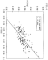
- a vehicle was prepared with a studless tire of 225/55R17 tire size fitted on the left front wheel and an acceleration sensor attached to the knuckle of the left front wheel. And the vehicle was operated at predetermined speeds (30 km/h to 80 km/h) on flat (smooth) roads (flat paved road and icy road), rough roads with some bumpiness (drainage pavement), and irregular (ungraded) roads to find the relationship between the calculated fluctuation range ⁇ ( ⁇ V w ) of variation in wheel speed and the calculated fluctuation range ⁇ (G x ) of unsprung fore-aft acceleration. The results are shown in FIGS. 2A and 2B .
- the information on the speed of left wheels was acquired from a vehicle information system (line of CAN).
- the horizontal axis of the diagrams represents ⁇ ( ⁇ V w ), and the vertical axis ⁇ (G x ).
- the lighter circles stand for the data of flat paved roads, the darker circles the data of icy roads, the smaller squares the data of drainage pavements, and the larger squares the data of irregular roads.
- the diagram of FIG. 2B is an enlargement of the neighborhood of the origin of the diagram of FIG. 2A , and the straight thick chain line in the diagram represents the fluctuation range criterion formula showing the relationship between ⁇ ( ⁇ V w ) and ⁇ (G x ). It is clear from the diagram that the data of flat roads are distributed mostly below the fluctuation range criterion formula, whereas the data of rough roads with some bumpiness are distributed mostly above it.
- the data of irregular roads are distributed outside the region R 0 enclosed with chain lines, that is, where the fluctuation range ⁇ ( ⁇ V w ) of variation in wheel speed is large or where the fluctuation range ⁇ (G x ) of unsprung fore-aft acceleration is large.
- a road surface condition under a traveling vehicle is estimated to be one of a flat road, a rough road with some bumpiness, and an irregular road.
- a road surface condition estimating apparatus 10Y provided on a knuckle 31 with an acceleration sensor 11 for detecting unsprung fore-aft acceleration and a second acceleration sensor 11Y as an unsprung lateral acceleration detecting means, as shown in FIG. 3 , can be used to estimate whether the flat (smooth) road estimated in the first embodiment is a flat road having a high road surface friction coefficient ⁇ ( ⁇ > 0.7) or a flat icy road having a low road surface friction coefficient ⁇ ( ⁇ ⁇ 0.2).
- the acceleration sensor 11 to be used may be an acceleration sensor capable of detecting accelerations in two directions, namely, the unsprung fore-aft acceleration G x and the unsprung lateral acceleration G y .
- the road surface condition estimating apparatus 10Y is equal to a road surface condition estimating apparatus 10 of the first embodiment further provided with a second acceleration sensor 11Y for detecting a lateral acceleration at an unsprung position of a vehicle (unsprung lateral acceleration) G y , an unsprung lateral acceleration fluctuation range calculating means 17 for calculating the fluctuation range ⁇ (G y ) of unsprung lateral acceleration, and a flat road discriminating means 18.
- the flat road discriminating means 18 discriminates the flat road estimated by the road surface condition estimating means 16 between a flat paved road and an icy road, using the second discriminant formula (see equation (3) below) representing a relationship between the fluctuation range ⁇ (G x ) of unsprung fore-aft acceleration calculated by the fluctuation range calculating means 14 and the fluctuation range ⁇ (G y ) of unsprung lateral acceleration calculated by the unsprung lateral acceleration fluctuation range calculating means 17.
- ⁇ G y a ⁇ ⁇ G y + b
- the unsprung parts of the vehicle vibrate by gaining forces from the ground contact areas or from tires themselves.
- the road surface friction coefficient ⁇ is high, the unsprung parts cannot move widely because of the strong restraining forces from the road surface. In particular, they cannot move easily in the lateral direction (axial direction of the tire) which is perpendicular to the rolling direction of the tire.
- the road surface friction coefficient ⁇ is low, the unsprung parts can move easily in the lateral direction because of reduced restraining forces from the road surface. As a result, the fluctuation range ⁇ (G y ) of unsprung lateral acceleration will be larger.
- the ratio of the fluctuation range ⁇ (G y ) of unsprung lateral acceleration to the fluctuation range ⁇ (G x ) of unsprung fore-aft acceleration is greater on road surfaces with a low road surface friction coefficient ⁇ .
- FIG. 4 shows the results of a test in which a vehicle with a studless tire of 225/55R17 tire size fitted on the left front wheel and an acceleration sensor attached to the knuckle of the left front wheel was operated at a predetermined speed (30 km/h) on a flat paved road ( ⁇ ⁇ 0.8) and an icy road ( ⁇ ⁇ 0.18).
- the diagram shows the relationship between the calculated fluctuation range ⁇ (G x ) of unsprung fore-aft acceleration and the calculated fluctuation range ⁇ (G y ) of unsprung lateral acceleration.
- the data of fluctuation range is based on calculation for every 6.5 meters of vehicular run.
- the flat road estimated by the road surface condition estimating means 16 is discriminated between a flat paved road and and an icy road from a relationship between the fluctuation range ⁇ (G x ) of unsprung fore-aft acceleration and the fluctuation range ⁇ (G y ) of unsprung lateral acceleration.
- the arrangement may be such that the absolute value
- of unsprung lateral acceleration are calculated and it is determined whether the estimated flat (smooth) road is a dry paved road or not from the relationship between the calculated
- FIG. 5 is a diagram showing a structure of a road surface condition estimating apparatus 10P according to a third embodiment of the present invention.
- the road surface condition estimating apparatus 10P is equal to the road surface condition estimating apparatus 10 of the first embodiment further provided with a second acceleration sensor 11Y for detecting the lateral acceleration at an unsprung position of a vehicle (unsprung lateral acceleration) G y , an acceleration product calculating means 19 for calculating the absolute value of the mean of G x ⁇ G y and the mean of the product
- the flat road discriminating means 18P discriminates the flat road estimated by the road surface condition estimating means 16 between a flat paved road and an icy road, using the absolute value (
- the unsprung parts of a traveling vehicle are subject to vibrations from the ground contact areas, forces generated by tires themselves, forces due to vehicular attitude changes communicated via the suspension, etc. And on flat roads whose road surface friction coefficient ⁇ is low, the unsprung parts of the vehicle can move more freely due to reduced restraints from the road surface. As a result, a phase difference can occur between the unsprung fore-aft acceleration G x and the unsprung lateral acceleration G y , thus changing the plus and minus of G x ⁇ G y .
- FIG. 6 shows the results of a test in which a vehicle with a studless tire of 225/55R17 tire size fitted on the left front wheel and an acceleration sensor attached to the knuckle of the left front wheel was operated at a fixed speed (40 km/h) on a flat paved road ( ⁇ ⁇ 0.8) and an icy road ( ⁇ ⁇ 0.18) .
- the diagram shows the relationship between
- the data of the means is based on calculation for every 6.5 meters of vehicular run.
- the road surface condition under a traveling vehicle is estimated to be one of a flat (smooth) road, a rough road with some bumpiness, and an irregular (ungraded) road.
- a rough road surface is a slippery road surface or not, when the road surface estimated in the first embodiment is a rough road surface.
- the rough road surface can be easily estimated to be a high ⁇ road, such as a drainage pavement, or a slippery road, such as a snowy road.
- FIG. 7 is a functional block diagram of a road surface condition estimating apparatus 10F according to a fourth embodiment of the present invention.
- the road surface condition estimating apparatus 10F includes an acceleration sensor 11 as an unsprung fore-aft acceleration detecting means, a wheel speed sensor 12 as a wheel speed detecting means, a wheel speed variation calculating means 13, a fluctuation range calculating means 14, a storage means 15, a road surface condition estimating means 16, a frequency analyzing means 21, a peak frequency extracting means 22, and a low ⁇ road discriminating means 23.
- the acceleration sensor 11, the wheel speed sensor 12, and the means from the wheel speed fluctuation range calculating means 13 to the road surface condition estimating means 16, having the same reference numerals as those in the first embodiment, are of the same structure as those in the first embodiment. Therefore the description thereof will be omitted.
- the frequency analyzing means 21, the peak frequency extracting means 22, and the low ⁇ road discriminating means 23 may also be constituted by computer software, for instance.
- the frequency analyzing means 21 obtains a frequency spectrum of unsprung fore-aft acceleration by performing a frequency analysis on the time-series waveform of the unsprung fore-aft acceleration detected by the acceleration sensor 11.
- FIG. 8 is a diagram showing examples of frequency spectra of unsprung fore-aft acceleration.
- the horizontal axis of the diagram represents the frequency, and the vertical axis the unsprung fore-aft acceleration G x .
- the thick solid line in the diagram shows a frequency spectrum when a vehicle traveled on a drainage pavement, and the thin solid line a frequency spectrum when the vehicle traveled on a snowy road.
- the peak frequency extracting means 22 extracts a peak frequency f p which is the frequency at the peak position within the band of 200 to 230 Hz of the frequency spectrum of unsprung fore-aft acceleration.
- characteristic vibrations of the tires are caused by impacts from the road surface.
- tire vibrations on a rough road such as a drainage pavement or a snowy road
- a flat road such as a dry asphalt road.
- the peak position, namely, the peak frequency f p of such vibrations tends to be dependent on the slipperiness of the road surface.
- a slippery road such as a snowy road whose road surface friction coefficient ⁇ is lower than 0.3
- the position of the peak frequency f p indicated by an arrow shifts toward lower frequencies as shown in FIG. 8 .
- the reason is considered to be that the dynamic bond (spring constant) between the road surface and the tire tread becomes weaker on a slippery road surface.
- the peak frequency can be observed on flat (smooth) roads such as dry asphalt roads.
- the vibration level is lower than that when a vehicle is operated on drainage pavements or snowy roads. Therefore, when the vibration level G x (f p ) at peak frequency f p is lower than a predetermined threshold value K, the peak frequency extracting means 22 does not extract the peak frequency f p and sends a signal indicating the road surface being a flat road surface to the low ⁇ road discriminating means 23.
- an acceleration sensor 11 detects an unsprung fore-aft acceleration G x , which is a fore-aft acceleration acting on the knuckle 31 and sends the data to a fluctuation range calculating means 14.
- a wheel speed sensor 12 detects a wheel speed V w and sends the data to a wheel speed variation calculating means 13.
- the wheel speed variation calculating means 13 calculates a variation ⁇ V w in wheel speed, which is a variation in wheel speed V w , and sends the data to the fluctuation range calculating means 14.
- the fluctuation range calculating means 14 calculates a fluctuation range ⁇ (G x ) of unsprung fore-aft acceleration G x and a fluctuation range ⁇ ( ⁇ V w ) of the variation ⁇ V w in wheel speed calculated by the wheel speed variation calculating means 13, respectively, and sends the data to a road surface condition estimating means 16.
- the road surface condition estimating means 16 estimates a road surface condition under a traveling vehicle to be one of a flat road, a rough road, and an irregular road, using the fluctuation range ⁇ (G x ) of unsprung fore-aft acceleration and fluctuation range ⁇ ( ⁇ V w ) of variation in wheel speed, the maximum value ⁇ GM of the fluctuation range of unsprung fore-aft acceleration and maximum value ⁇ VM of the fluctuation range of variation in wheel speed, and the fluctuation range criterion formula representing a relationship between the fluctuation range ⁇ ( ⁇ V w ) of variation in wheel speed and the fluctuation range ⁇ (G x ) of unsprung fore-aft acceleration. More specifically, the estimation is done as follows:
- the road surface under a traveling vehicle is determined to be a rough road surface by the road surface condition estimating means 16, it is further estimated whether the rough road surface is a slippery road surface or not. More specifically, the detected time-series waveform of unsprung fore-aft acceleration G x is subjected to a frequency analysis by the frequency analyzing means 21 to find a frequency spectrum of the unsprung fore-aft acceleration as shown in FIG. 8 . And from this frequency spectrum, a peak frequency f p , which is a frequency at the peak position within the band of 200 to 230 Hz, is extracted.
- the road surface under a traveling vehicle is estimated to be a road surface whose road surface friction coefficient is high ( ⁇ > 0.7), such as a drainage pavement.
- the road surface under a traveling vehicle is estimated to be a road surface whose road surface friction coefficient is low ( ⁇ ⁇ 0.3), such as a snowy road.
- the road surface when the road surface is a rough (bumpy) road surface, the road surface can be easily estimated to be a high ⁇ road surface, such as a drainage pavement, or a slippery road surface, such as a snowy road.
- a vehicle having an acceleration sensor attached to the knuckle of the left front wheel was operated at predetermined speeds (40 km/h, 50 km/h, and 60 km/h) on a drainage pavement and a snowy road. And a frequency spectrum was calculated for every 6.5 meters of vehicular run, and the frequency spectra of the latest five consecutive runs were averaged. Then the peak frequency f p in the band of 200 to 230 Hz of this frequency spectrum was extracted, and the relationship between the wheel speed V w and the peak frequency f p was found. The results are shown in FIG. 9 .
- the tires used was studless tires of 225/55R17 size.
- the information on the speed of left wheels was acquired from a vehicle information system (line of CAN).
- the horizontal axis of the diagram represents the wheel speed, and the vertical axis the frequency.
- the "+” marks (crosses) stand for the data on the drainage pavement, and the “ ⁇ ” marks the data on the snowy road.
Description
- The present invention relates to a method and apparatus for estimating a road surface condition under a traveling vehicle.
- To enhance the travel stability of a vehicle, it is desired that the road surface condition or the ground contact state of the tire is estimated with accuracy and the data thus obtained is fed back to vehicle control. If the road surface condition or the ground contact state of the tire can be estimated in time, then it will be possible to operate such advanced control as ABS (antilock braking system) braking before taking any danger avoidance action such as braking, accelerating, or steering. With such facility, there will be a marked boost in the safety of vehicular operation.
- There are a number of proposed methods for estimating a road surface condition. In one of such methods (see
Patent Document 1, for instance), a tire used for the estimation of road surface conditions has deformable structural areas, each including sipes, formed at a specific pitch P circumferentially in the shoulder region of the tire. And the vibrations of the running tire tread are detected by an acceleration sensor to acquire a vibration spectrum, and at the same time the wheel speed is measured by a wheel speed sensor. Then the road surface condition is estimated from the vibration level caused by the deformable structural areas at the detected frequency calculated from the wheel speed measured by the wheel speed sensor and the pitch P. - Also, there are methods proposed for estimating the road-hugging performance of a wheel, using a kinetic state quantity of the wheel (see
Patent Document 2, for instance) . As described inPatent Document 2, an FFT analysis is performed on the vibration components in the unsprung resonant frequency range extracted from a wheel speed. Then the maximum value Gv of gain of the obtained frequency component in the analysis is compared with the predetermined reference value Gv0. And if the maximum value Gv of gain is greater than the reference value Gv0, the road-hugging performance is determined to be poor, and if the maximum value Gv of gain is smaller than the reference value Gv0, the road-hugging performance is determined to be satisfactory. - Also, there are various road surface shape detecting apparatuses disclosed. In one of them (see
Patent Document 3, for instance), the vibrations of unsprung parts of a vehicle when the vehicle goes over a road surface bump are detected by acceleration sensors attached to the unsprung parts of the right and left wheels. At the same time, the difference Ap-p between the maximum value and the minimum value of the unsprung vibrations is calculated. Then the road surface bump height X1 and the road surface bump width X2 are estimated using the difference Ap-p between the maximum value and the minimum value and a multiple regression equation representing a predetermined relationship between the road surface bump height X1 and road surface bump width X2 and the difference Ap-p between the maximum value and the minimum value. Note here that the multiple regression equation is determined for each of wheel speeds. - Attention is drawn to the disclosure of
JP2006-131136 -
- Patent Document 1: Japanese Unexamined Patent Application Publication No.
2010-274906 - Patent Document 2: Japanese Unexamined Patent Application Publication No.
8-15069 - Patent Document 3: Japanese Patent No.
3186474 - However, the method using a tire dedicated to the estimation of a road surface condition poses a problem that tread pattern design is subject to reduced freedom because of certain limitations on the tread pattern.
- Also, the method for estimating the road-hugging performance of a wheel by use of a kinetic state quantity of the wheel relies on the wheel speed only that is used actually as the kinetic state quantity of the wheel. As a result, tire or suspension data must be added if a road surface condition is to be estimated with accuracy.
- Also, the method for detecting vehicular unsprung vibration uses the unsprung resonance of about 11 to 12 Hz that occurs when the vehicle goes over a road surface bump. Therefore, while it is possible to estimate the shape of a transient road surface bump, it is difficult to estimate the road surface properties related to its slipperiness.
- The present invention has been made in view of the above-described problems, and an object thereof is to provide a method and apparatus for accurately estimating a road surface condition under a traveling vehicle using unsprung fore-aft acceleration and wheel speed data.
- Through a systematic and exhaustive investigation, the inventor has reached the present invention based on the following findings: The variation ΔVw in wheel speed Vw and the unsprung fore-aft acceleration Gx are in proportional relationship with each other. And the relationship between the fluctuation range σ(ΔVw) of the variation ΔVw in wheel speed Vw and the fluctuation range σ(Gx) of the unsprung fore-aft acceleration Gx depends on road surface conditions, particularly, the fluctuation range σ(g) of vibration g due to the roughness (bumpiness) of the road surface. Therefore, the road surface condition under a traveling vehicle can be estimated with accuracy by detecting the wheel speed Vw and the unsprung fore-aft acceleration Gx and finding a relationship between the value of the fluctuation range σ(ΔVw) of the variation ΔVw in wheel speed Vw and the value of the fluctuation range σ(Gx) of the unsprung fore-aft acceleration Gx.
- Accordingly, the present invention provides a method for estimating a road surface condition, comprising the steps of: detecting an unsprung fore-aft acceleration Gx by an acceleration sensor attached to an unsprung position of a vehicle; detecting a wheel speed Vw; calculating a variation ΔVw in the detected wheel speed; calculating a fluctuation range σ(ΔVw) of the calculated variation in wheel speed and a fluctuation range σ(Gx) of the detected unsprung fore-aft acceleration; and estimating a road surface condition from a relationship between the fluctuation range σ(ΔVw) of the variation in wheel speed and the fluctuation range σ(Gx) of the unsprung fore-aft acceleration wherein the step of estimating a road surface condition further includes the steps of: estimating whether the road surface under a traveling vehicle is a rough (bumpy) road surface or not from a relationship between the fluctuation range of the variation in wheel speed and the fluctuation range of the unsprung fore-aft acceleration; and calculating, when the estimated road surface is a rough road surface, a peak frequency at a peak position within a band of 200 to 230 Hz of a frequency spectrum obtained by a frequency analysis of the detected unsprung fore-aft acceleration and estimating whether the rough road surface is a slippery road surface or not from the peak frequency and the wheel speed, wherein in the step of estimating whether the road surface under a traveling vehicle is a rough road surface or not, the road surface under a traveling vehicle is estimated to be a rough road surface when the calculated fluctuation range of the unsprung fore-aft acceleration is greater than the calculated value of the fluctuation range of the unsprung fore-aft acceleration obtained by substituting the fluctuation range of the variation in wheel speed into a predetermined fluctuation range criterion formula representing a relationship between the fluctuation range of unsprung fore-aft acceleration and the fluctuation range of variation in wheel speed, and, wherein in the step of estimating whether the rough road surface is a slippery road surface or not, the rough road surface is estimated to be a slippery road surface whose road surface friction coefficient µ is lower than 0.3 when the detected peak frequency is lower than the calculated value of peak frequency obtained by substituting the detected wheel speed into a frequency criterion formula representing a predetermined relationship between peak frequency and wheel speed.
- Note that the "rough (bumpy) road surface" is a road surface intermediate between irregular (ungraded) road surfaces which do not allow normal road-hugging performance of tires and flat (smooth) road surfaces with little bumpiness, such as a dry paved road surface.
- When the road surface is rough, σ(Gx) will be greater than the σ(Gx) that is expected from σ(ΔVw). Hence, it is possible to estimate easily the road surface under a traveling vehicle to be a rough road surface with some bumpiness, such as a drainage pavement, or a flat (smooth) road surface with little bumpiness, such as a dry paved road.
- It is to be noted that the quantities usable as the fluctuation range σ(ΔVw) of variation in wheel speed and the fluctuation range σ(Gx) of unsprung fore-aft acceleration Gx are the data of ΔVw within a predetermined time (e.g., 0.5 seconds) and any quantity representing the data variation, such as the standard deviation or a half-value width when the data of Gx is assumed to be in a gauss distribution.
- If the road surface is bumpy, then σ(Gx) will be greater than the σ(Gx) that can be expected from σ(ΔVw). Therefore, the road surface under a traveling vehicle can be estimated easily to be a rough road surface, such as a drainage pavement, or a flat road surface with little bumpiness, such as a dry paved road.
- Further, when the road surface is a rough road surface, it is estimated whether the rough road surface is a slippery road surface of not, from a peak frequency fp, which is a frequency at the peak position within a band of 200 to 230 Hz of a frequency spectrum obtained by a frequency analysis of an unsprung fore-aft acceleration, and a wheel speed Vw. Accordingly, it is possible to estimate with accuracy whether the rough road surface is a not-so-slippery road surface, such as a drainage pavement, or a slippery road surface, such as a snowy road surface.
- Note that the fluctuation range criterion formula is, for example, a primary expression showing a relationship between the fluctuation range of variation in wheel speed and the fluctuation range of unsprung fore-aft acceleration found by operating a test vehicle on various road surfaces (see equation (1) below).

- Also, note that the frequency criterion formula is, for example, a primary expression showing a relationship between the peak frequency fp and the wheel speed Vw found by operating a test vehicle on drainage pavements and snowy roads (see equation (2) below).

- Also, the quantities usable as the fluctuation range σ(ΔVw) of variation in wheel speed and the fluctuation range σ(Gx) of unsprung fore-aft acceleration Gx are the data of ΔVw within a predetermined time (e.g., 0.5 seconds) and any quantity representing the data variation, such as the standard deviation σ or a half-value width when the data of Gx is assumed to be in a gauss distribution.
- Also, preferably, in the step of estimating a road surface condition, the road surface under a traveling vehicle is estimated to be a flat (smooth) road surface when the calculated fluctuation range σ(Gx) of the unsprung fore-aft acceleration is equal to or smaller than the calculated value of the fluctuation range of the unsprung fore-aft acceleration obtained by substituting the fluctuation range σ(ΔVw) of the variation in wheel speed into a fluctuation range criterion formula representing a predetermined relationship between the fluctuation range of variation in wheel speed and the fluctuation range of unsprung fore-aft acceleration (see equation (1) below).

- Thus, a fluctuation range criterion formula representing a relationship between the fluctuation range of unsprung fore-aft acceleration and the fluctuation range of variation in wheel speed is found in advance by operating a test vehicle on various road surfaces. Then a road surface condition is estimated, using this fluctuation range criterion formula. Therefore, the road surface under a traveling vehicle can be estimated with accuracy to be a rough road surface with some bumpiness or a flat road surface.
- Also, preferably, in the step of estimating a road surface condition, the road surface under a traveling vehicle is estimated to be an irregular (ungraded) road surface when the fluctuation range of the variation in wheel speed exceeds a predetermined maximum fluctuation range of variation in wheel speed or when the calculated fluctuation range of the unsprung fore-aft acceleration exceeds a predetermined maximum fluctuation range of acceleration.
- The "irregular (ungraded) road surface" is a road surface, such as an unpaved or cracked road surface or a sherbet-like snowy road surface with much bumpiness and irregularity, which does not allow normal road-hugging performance of tires. When the road surface under a traveling vehicle is an irregular road surface, one of both of the fluctuation range of wheel speed and the fluctuation range of unsprung fore-aft acceleration may be greater. Hence, the accuracy in estimating a road surface condition under a traveling vehicle can be further improved if the road surface is classified into three categories of irregular road, rough road with some bumpiness, and flat road.
- Also, preferably the method which further includes the steps of detecting an unsprung lateral acceleration Gy, in addition to the unsprung fore-aft acceleration Gx, calculating a fluctuation range σ(Gy) of the unsprung lateral acceleration, and determining whether the estimated flat road surface is a dry paved road surface or not from a relationship between the calculated fluctuation range σ(Gy) of the unsprung lateral acceleration and the fluctuation range σ(Gx) of the unsprung fore-aft acceleration.
- Thus, by finding the relationship between the value of the fluctuation range σ(Gx) of the unsprung fore-aft acceleration and the value of the fluctuation range σ(Gy) of the unsprung lateral acceleration, it is possible to determine whether the estimated flat road is a flat dry paved road or a flat icy road. Therefore, the road surface condition under a traveling vehicle can be estimated with greater accuracy.
- Also, preferably, the method which further includes the steps of detecting an unsprung lateral acceleration Gy, in addition to the unsprung fore-aft acceleration Gx, calculating an absolute value of the mean of the products of the unsprung fore-aft acceleration and the unsprung lateral acceleration, |ave (Gx×Gy)|, and a mean of the products of the absolute value |Gx| of the unsprung fore-aft acceleration and the absolute value |Gy| of the unsprung lateral acceleration, ave (|Gx|×|Gy|), and determining whether the estimated flat road surface is a dry paved road surface or not from a relationship between the calculated |ave (Gx×Gy)| and ave (|Gx|×|Gy|).
- Thus, by finding the relationship between the value of |ave (Gx×Gy)| and the value of ave (|Gx|×|Gy|), it is possible to determine whether the estimated flat road is a flat dry paved road or a flat icy road. Therefore, the road surface condition under a traveling vehicle can be estimated with greater accuracy.
- [DELETED]
- [DELETED]
- Also, preferably, in the step of estimating a road surface condition, is a rough/bumpy road surface or not, the road surface under a traveling vehicle is estimated to be an irregular (ungraded) road surface when the calculated fluctuation range of the variation in wheel speed exceeds a predetermined maximum fluctuation range of variation in wheel speed or when the fluctuation range of the unsprung fore-aft acceleration exceeds a predetermined maximum fluctuation range of acceleration.
- Here the "irregular (ungraded) road" is a road surface that does not allow normal road-hugging performance of tires as described earlier. When the road surface under a traveling vehicle is an irregular road, one or both of the fluctuation range of variation in wheel speed and the fluctuation range of unsprung fore-aft acceleration will be greater than normal.
- Thus, when σ(ΔVw) > σAM or σ(Gx) > σGM, the road surface is estimated to be an irregular road, thereby distinguishing it from rough road surfaces, such as drainage pavements or snowy roads.
- Accordingly, the road surface under a traveling vehicle can be estimated to be an irregular road reliably.
- Also, the present invention provides a road surface condition estimating apparatus that realizes the initially described method for estimating a road surface condition. And the apparatus comprises an unsprung fore-aft acceleration detecting means disposed at an unsprung position of a vehicle to detect an unsprung fore-aft acceleration Gx, a wheel speed detecting means for detecting wheel speed Vw, a wheel speed variation calculating means for calculating a variation ΔVw in the detected wheel speed, a fluctuation range calculating means for calculating a fluctuation range σ(ΔVw) of the variation in wheel speed and a fluctuation range σ(Gx) of the unsprung fore-aft acceleration, a storage means for storing a fluctuation range criterion formula (σ(Gx) = K · σ(ΔVw) + σ(g)) representing a predetermined relationship between the fluctuation range of variation in wheel speed and the fluctuation range of unsprung fore-aft acceleration, and a road surface condition estimating means for estimating a road surface condition under a traveling vehicle, using the calculated fluctuation range of the variation in wheel speed and fluctuation range of the unsprung fore-aft acceleration and the fluctuation range criterion formula. The apparatus further comprises a frequency analyzing means for performing a frequency analysis on the detected unsprung fore-aft acceleration, and a peak frequency calculating means for calculating a peak frequency at a peak position within a band of 200 to 230 Hz of a frequency spectrum obtained by the frequency analysis. And the apparatus is such that the storage means stores a predetermined maximum fluctuation range of wheel speed, a predetermined maximum fluctuation range of unsprung fore-aft acceleration, and a fluctuation range criterion formula representing a relationship between the fluctuation range of unsprung fore-aft acceleration and the fluctuation range of variation in wheel speed, and the road surface condition estimating means determines the road surface to be a rough road surface when the calculated fluctuation range of the unsprung fore-aft acceleration is greater than the calculated value of the fluctuation range of unsprung fore-aft acceleration obtained by substituting the fluctuation range of the variation in wheel speed into the fluctuation range criterion formula and, in addition, when the fluctuation range of the variation in wheel speed and the fluctuation range of the unsprung fore-aft acceleration are smaller than the maximum fluctuation range of variation in wheel speed and the maximum fluctuation range of unsprung fore-aft acceleration, respectively. And also the apparatus is such that, when the determined road surface is a rough road surface, the road surface condition estimating means estimates the rough road surface to be a slippery road surface whose road surface friction coefficient µ is lower than 0.3 when the detected peak frequency is lower than the calculated value of peak frequency obtained by substituting the detected wheel speed into a frequency criterion formula representing a predetermined relationship between peak frequency and wheel speed.
- As a result, it is possible to estimate with accuracy whether the road surface under a traveling vehicle is a rough road surface or not. At the same time, when the road surface is a rough road surface, it can be easily estimated whether the road surface is a slippery road surface or not.
- By employing a structure as described above, a road surface condition estimating apparatus can be implemented that can easily estimate whether the road surface under a traveling vehicle is a rough road surface with some bumpiness, such as a drainage pavement, or a flat road surface with little bumpiness, such as a dry paved road.
- Also, the present invention provides a road surface condition estimating apparatus which further includes an unsprung lateral acceleration detecting means disposed at an unsprung position of a vehicle to detect an unsprung lateral acceleration Gy, and an unsprung lateral acceleration fluctuation range calculating means for calculating a fluctuation range σ(Gy) of the detected unsprung lateral acceleration. And the apparatus is such that the road surface condition estimating means determines whether the estimated road surface is a dry paved road or not from a relationship between the calculated fluctuation range σ(Gy) of the unsprung lateral acceleration and fluctuation range σ(Gx) of the unsprung fore-aft acceleration.
- This makes it possible to determine with certainty whether the estimated road surface is a flat dry paved road or a flat icy road.
- Also, the present invention provides a road surface condition estimating apparatus which further includes an unsprung lateral acceleration detecting means disposed at an unsprung position of a vehicle to detect an unsprung lateral acceleration Gy, and an acceleration product calculating means for calculating an absolute value of the mean of the products of the unsprung fore-aft acceleration Gx and the unsprung lateral acceleration Gy, |ave (Gx×Gy)|, and a mean of the products of the absolute value |Gx| of the unsprung fore-aft acceleration and the absolute value |Gy| of the unsprung lateral acceleration, ave (|Gx|×|Gy|). And the apparatus is such that the road surface condition estimating means determines whether the estimated road surface is a dry paved road or not from a relationship between |ave (Gx×Gy)| and ave (|Gx|×|Gy|).
- This also makes it possible to determine with certainty whether the estimated road surface is a flat dry paved road or a flat icy road.
- [DELETED]
- It is to be understood that the foregoing summary of the invention does not necessarily recite all the features essential to the invention, and subcombinations of all these features are intended to be included in the invention.
-
-
FIG. 1 is a diagram showing a structure of a road surface condition estimating apparatus in accordance with the first embodiment which is not according to the present invention. -
FIG. 2 is diagrams showing a relationship between the fluctuation range of variation in wheel speed and the fluctuation range of unsprung fore-aft acceleration. -
FIG. 3 is a diagram showing a structure of a road surface condition estimating apparatus in accordance with the second embodiment which is not according to the present invention. -
FIG. 4 is a diagram showing a relationship between the fluctuation range of unsprung fore-aft acceleration and the fluctuation range of unsprung lateral acceleration. -
FIG. 5 is a diagram showing a structure of a road surface condition estimating apparatus in accordance with the third embodiment which is not according to the present invention. -
FIG. 6 is a diagram showing a relationship between the absolute value of the mean of the product of the fluctuation range of unsprung fore-aft acceleration and the unsprung lateral acceleration and the mean of the product of the absolute value of the fluctuation range of unsprung fore-aft acceleration and the absolute value of unsprung lateral acceleration. -
FIG. 7 is a diagram showing a structure of a road surface condition estimating apparatus in accordance with the fourth embodiment of the present invention. -
FIG. 8 is a diagram showing examples of frequency spectra of unsprung fore-aft acceleration. -
FIG. 9 is a diagram showing a relationship between the wheel speed and the peak frequency. - Hereinafter, the invention will be described based on a preferred embodiment which is not intended to limit the scope of the claims of the present invention but exemplify the invention. All of the features and the combinations thereof described in the embodiment are not necessarily essential to the invention.
-
FIG. 1 is a functional block diagram of a road surfacecondition estimating apparatus 10 according to a first embodiment which is not according to the present invention. - The road surface
condition estimating apparatus 10 includes anacceleration sensor 11 as an unsprung fore-aft acceleration detecting means, awheel speed sensor 12 as a wheel speed detecting means, a wheel speed variation calculating means 13, a fluctuation range calculating means 14, a storage means 15, and a road surface condition estimating means 16. Note that the means from the fluctuation range calculating means 14 to the road surface condition estimating means 16 may be constituted by computer software, for instance. - As shown in
FIG. 1 , theacceleration sensor 11, which is attached to a knuckle 31, detects the unsprung fore-aft acceleration Gx. The knuckle 31 is a non-rotating-side member (unsprung member) of awheel unit 30, which is coupled via a bearing to a wheel hub 33 rotating together with thewheel 32 with a tire T fitted thereon. The knuckle 31 is suspended from the not-shown vehicle body by a suspension member, such as ashock absorber 34. - The
wheel speed sensor 12 detects the rotational speed Vw of a wheel (hereinafter referred to as wheel speed). Employed in this embodiment to detect the angle of rotation of the wheel is a wheel speed sensor of a known electromagnetic induction type, which is equipped with a rotor having gear teeth on its periphery and rotating together with the wheel, a yoke constituting a magnetic circuit in combination with the rotor, and a coil for detecting flux changes of the magnetic circuit. The yoke and the coil are mounted on the knuckle 31. - In the present embodiment, as will be described later, the data of wheel speed Vw and the data of unsprung fore-aft acceleration Gx to be used are their respective values after an A-D conversion of the sampled outputs of the
wheel speed sensor 12 and theacceleration sensor 11 so as to enable calculation of the fluctuation ranges σ(ΔVw) and σ(Gx). - It should be noted that with a vehicle equipped with a vehicle control means for controlling its running condition using a network, such as CAN (controller area network), it is preferable that the data of wheel speed Vw is obtained from the network.
- The wheel speed variation calculating means 13 calculates the variation ΔVw in wheel speed Vw detected by the
wheel speed sensor 12. The difference in wheel speed between sampling points can be used as the variation ΔVw in wheel speed. - The fluctuation range calculating means 14 calculates the fluctuation range σ(Gx) of the unsprung fore-aft acceleration Gx detected by the
acceleration sensor 11 and the fluctuation range σ(ΔVw) of the variation ΔVw in wheel speed calculated by the wheel speed variation calculating means 13. Since the data of unsprung fore-aft acceleration Gx and the data of the variation ΔVw in wheel speed for a predetermined time T (for example, T = 0.5 seconds) can be approximated by gauss distributions, the fluctuation range σ(Gx) is used as the standard deviation σ for the respective distributions in the present embodiment. - It should be noted that the fluctuation range σ, which may be any quantity representing data variation within a predetermined time length, may be a half-value width or 2σ, for instance.
- The storage means 15 stores the predetermined maximum value σGM of the fluctuation range of unsprung fore-aft acceleration, the predetermined maximum value σAM of the fluctuation range of variation in wheel speed, and a fluctuation range criterion formula, which is a primary expression (see
equation 1 below) showing a predetermined relationship between the fluctuation range σ(ΔVw) of variation in wheel speed and the fluctuation range σ(Gx) of unsprung fore-aft acceleration.
- The fluctuation range criterion formula (1) is an expression obtained using the data of σ(Gx) and σ(ΔVw) which were obtained by operating a test vehicle on a variety of road surfaces . Using these data, it is also possible to set the maximum value σGM of the fluctuation range of unsprung fore-aft acceleration and the maximum value σAM of the fluctuation range of variation in wheel speed.
- The road surface condition estimating means 16 estimates a road surface condition under a traveling vehicle, using the fluctuation range σ(Gx) of unsprung fore-aft acceleration and fluctuation range σ(ΔVw) of variation in wheel speed calculated by the fluctuation range calculating means 14, the maximum value σGM of the fluctuation range of unsprung fore-aft acceleration and maximum value σAM of the fluctuation range of variation in wheel speed taken from the storage means 15, and the fluctuation range criterion formula representing a relationship between the fluctuation range σ(ΔVw) of variation in wheel speed and the fluctuation range σ(Gx) of unsprung fore-aft acceleration.
- More specifically, the road surface condition estimating means 16 estimates the road surface to be a flat road surface with little bumpiness, such as a dry paved road, when σ(Gx) ≤ K • σ(ΔVw) + σ(g), that is, when the calculated fluctuation range σ(Gx) of unsprung fore-aft acceleration is smaller than the calculated value of the fluctuation range of unsprung fore-aft acceleration (σcal(Gx) = K · σ(ΔVw) + σ(g)), which is calculated by substituting the calculated fluctuation range σ(ΔVw) of variation in wheel speed into the fluctuation range criterion formula (1), or estimates it to be a rough road with some bumpiness, such as a drainage pavement, when the calculated value of σ(Gx) is greater than the calculated value of σcal(Gx).
- In this embodiment, when the fluctuation range σ(Gx) of unsprung fore-aft acceleration is greater than the maximum value σGM of the fluctuation range of unsprung fore-aft acceleration or when the fluctuation range σ(ΔVw) of variation in wheel speed is greater than the maximum value σAM of the fluctuation range of variation in wheel speed, the road surface condition estimating means 16 determines the road surface to be an irregular (ungraded) road surface, such as an unpaved or cracked road surface or a sherbet-like snowy road surface with much bumpiness and irregularity, which does not allow normal road-hugging performance of tires. Thus, the road surface condition estimating means 16 distinguishes this road surface from a rough road surface with some bumpiness, such as a drainage pavement. Accordingly, the road surface condition estimating means 16 can estimate the road surface to be in one of three different conditions, namely, a flat (smooth) road surface, a rough road surface with some bumpiness, and an irregular (ungraded) road surface.
- Next, a description is given of a method for estimating a road surface condition using the road surface
condition estimating apparatus 10. - First an
acceleration sensor 11 detects an unsprung fore-aft acceleration Gx, which is a fore-aft acceleration acting on a knuckle 31 and sends the data to a fluctuation range calculating means 14. At the same time, awheel speed sensor 12 detects a wheel speed Vw and sends the data to a wheel speed variation calculating means 13. - The wheel speed variation calculating means 13 calculates a variation ΔVw in wheel speed, which is a variation in wheel speed Vw, and sends the data to the fluctuation range calculating means 14.
- The fluctuation range calculating means 14 calculates a fluctuation range σ(Gx) of unsprung fore-aft acceleration Gx and a fluctuation range σ(ΔVw) of the variation ΔVw in wheel speed calculated by the wheel speed variation calculating means 13, respectively, and sends the data to a road surface condition estimating means 16.
- The road surface condition estimating means 16 estimates a road surface condition under a traveling vehicle to be one of a flat road, a rough road, and an irregular road, using the fluctuation range σ(Gx) of unsprung fore-aft acceleration and fluctuation range σ(ΔVw) of variation in wheel speed, the maximum value σGM of the fluctuation range of unsprung fore-aft acceleration and maximum value σVM of the fluctuation range of variation in wheel speed, and the fluctuation range criterion formula representing a relationship between the fluctuation range σ(ΔVw) of variation in wheel speed and the fluctuation range σ(Gx) of unsprung fore-aft acceleration. More specifically, the estimation is done as follows:
- A: σ(ΔVw) > σAM or σ(Gx) > σGM: an irregular (ungraded) road
- B: σ(Gx) > K · σ(ΔVw) + σ(g) : a rough road with some bumpiness
- C: σ(Gx) ≤ K · σ(ΔVw) + σ(g) : a flat (smooth) road
- Thus, using a road surface
condition estimating apparatus 10 according to the first embodiment, the property of a road surface, for example, whether it is extremely bumpy like an irregular road surface or least bumpy like a flat road surface, can be detected easily without a sensor attached to the tire. - In the first embodiment thus far described, the wheel speed Vw is found from the output of the
wheel speed sensor 12. However, it should be noted that with a vehicle provided with an information system (example: CAN (controller area network)) in a vehicle control means for controlling its running condition, it is preferable that the wheel speed Vw is obtained from the information system. This will further simplify the apparatus. - A vehicle was prepared with a studless tire of 225/55R17 tire size fitted on the left front wheel and an acceleration sensor attached to the knuckle of the left front wheel. And the vehicle was operated at predetermined speeds (30 km/h to 80 km/h) on flat (smooth) roads (flat paved road and icy road), rough roads with some bumpiness (drainage pavement), and irregular (ungraded) roads to find the relationship between the calculated fluctuation range σ(ΔVw) of variation in wheel speed and the calculated fluctuation range σ(Gx) of unsprung fore-aft acceleration. The results are shown in
FIGS. 2A and 2B . - Note that the data of fluctuation range is based on calculation for every 6.5 meters of vehicular run.
- Also, the information on the speed of left wheels was acquired from a vehicle information system (line of CAN).
- In
FIGS. 2A and 2B , the horizontal axis of the diagrams represents σ(ΔVw), and the vertical axis σ(Gx). The lighter circles stand for the data of flat paved roads, the darker circles the data of icy roads, the smaller squares the data of drainage pavements, and the larger squares the data of irregular roads. - The diagram of
FIG. 2B is an enlargement of the neighborhood of the origin of the diagram ofFIG. 2A , and the straight thick chain line in the diagram represents the fluctuation range criterion formula showing the relationship between σ(ΔVw) and σ(Gx). It is clear from the diagram that the data of flat roads are distributed mostly below the fluctuation range criterion formula, whereas the data of rough roads with some bumpiness are distributed mostly above it. It has been confirmed therefore that it is possible to estimate a road surface under a traveling vehicle to be a flat road with little bumpiness, such as a dry paved road, or a rough road with some bumpiness, such as a drainage pavement, by finding the relationship between the fluctuation range σ(ΔVw) of variation in wheel speed and the fluctuation range σ(Gx) of unsprung fore-aft acceleration. - Also, as shown in
FIGS. 2A and 2B , the data of irregular roads are distributed outside the region R0 enclosed with chain lines, that is, where the fluctuation range σ(ΔVw) of variation in wheel speed is large or where the fluctuation range σ(Gx) of unsprung fore-aft acceleration is large. - Accordingly, it has also been confirmed that by appropriately setting the maximum value σGM of the fluctuation range σ(ΔVw) of unsprung fore-aft acceleration and maximum value σVM of the fluctuation range σ(Gx) of variation in wheel speed, it is possible to reliably estimate whether or not the road surface is an irregular road surface, such as an unpaved or cracked road surface or a sherbet-like snowy road surface, which is extremely bumpy and irregular, thus not allowing normal road-hugging performance of tires.
- In the foregoing first embodiment, a road surface condition under a traveling vehicle is estimated to be one of a flat road, a rough road with some bumpiness, and an irregular road. However, a road surface condition estimating apparatus 10Y provided on a knuckle 31 with an
acceleration sensor 11 for detecting unsprung fore-aft acceleration and a second acceleration sensor 11Y as an unsprung lateral acceleration detecting means, as shown inFIG. 3 , can be used to estimate whether the flat (smooth) road estimated in the first embodiment is a flat road having a high road surface friction coefficient µ (µ > 0.7) or a flat icy road having a low road surface friction coefficient µ (µ < 0.2). - Note that the
acceleration sensor 11 to be used may be an acceleration sensor capable of detecting accelerations in two directions, namely, the unsprung fore-aft acceleration Gx and the unsprung lateral acceleration Gy. - The road surface condition estimating apparatus 10Y is equal to a road surface
condition estimating apparatus 10 of the first embodiment further provided with a second acceleration sensor 11Y for detecting a lateral acceleration at an unsprung position of a vehicle (unsprung lateral acceleration) Gy, an unsprung lateral acceleration fluctuation range calculating means 17 for calculating the fluctuation range σ(Gy) of unsprung lateral acceleration, and a flat road discriminating means 18. - The flat road discriminating means 18 discriminates the flat road estimated by the road surface condition estimating means 16 between a flat paved road and an icy road, using the second discriminant formula (see equation (3) below) representing a relationship between the fluctuation range σ(Gx) of unsprung fore-aft acceleration calculated by the fluctuation range calculating means 14 and the fluctuation range σ(Gy) of unsprung lateral acceleration calculated by the unsprung lateral acceleration fluctuation range calculating means 17.

- Here a description is given of the second discriminant formula.
- During the travel of a vehicle, the unsprung parts of the vehicle vibrate by gaining forces from the ground contact areas or from tires themselves. When the road surface friction coefficient µ is high, the unsprung parts cannot move widely because of the strong restraining forces from the road surface. In particular, they cannot move easily in the lateral direction (axial direction of the tire) which is perpendicular to the rolling direction of the tire. However, when the road surface friction coefficient µ is low, the unsprung parts can move easily in the lateral direction because of reduced restraining forces from the road surface. As a result, the fluctuation range σ(Gy) of unsprung lateral acceleration will be larger.
- In other words, the ratio of the fluctuation range σ(Gy) of unsprung lateral acceleration to the fluctuation range σ(Gx) of unsprung fore-aft acceleration is greater on road surfaces with a low road surface friction coefficient µ.
-
FIG. 4 shows the results of a test in which a vehicle with a studless tire of 225/55R17 tire size fitted on the left front wheel and an acceleration sensor attached to the knuckle of the left front wheel was operated at a predetermined speed (30 km/h) on a flat paved road (µ ≅ 0.8) and an icy road (µ ≅ 0.18). The diagram shows the relationship between the calculated fluctuation range σ(Gx) of unsprung fore-aft acceleration and the calculated fluctuation range σ(Gy) of unsprung lateral acceleration. The data of fluctuation range is based on calculation for every 6.5 meters of vehicular run. - It is clear that the data on a flat paved road indicated by circles are distributed mostly below the straight chain line and the data on an icy road indicated by crosses mostly above the straight line. Accordingly, the above-mentioned second discriminant formula, if it represents the straight line, makes it possible to discriminate the flat road estimated by the road surface condition estimating means 16 between a flat paved road and an icy road.
- In the second embodiment, the flat road estimated by the road surface condition estimating means 16 is discriminated between a flat paved road and and an icy road from a relationship between the fluctuation range σ(Gx) of unsprung fore-aft acceleration and the fluctuation range σ(Gy) of unsprung lateral acceleration. However, the arrangement may be such that the absolute value |Gx×Gy| of the product of unsprung fore-aft acceleration Gx and unsprung lateral acceleration Gy (absolute value of the mean of products actually) and the product |Gx|×|Gy| of the absolute value |Gx| of unsprung fore-aft acceleration and the absolute value |Gy| of unsprung lateral acceleration (mean of the products of absolute values actually) are calculated and it is determined whether the estimated flat (smooth) road is a dry paved road or not from the relationship between the calculated |Gx×Gy| and |Gx|×|Gy|.
-
FIG. 5 is a diagram showing a structure of a road surface condition estimating apparatus 10P according to a third embodiment of the present invention. The road surface condition estimating apparatus 10P is equal to the road surfacecondition estimating apparatus 10 of the first embodiment further provided with a second acceleration sensor 11Y for detecting the lateral acceleration at an unsprung position of a vehicle (unsprung lateral acceleration) Gy, an acceleration product calculating means 19 for calculating the absolute value of the mean of Gx×Gy and the mean of the product |Gx|×|Gy| of the absolute value |Gx| of Gx and the absolute value |Gy| of Gy, and a flat road discriminating means 18P. - The flat road discriminating means 18P discriminates the flat road estimated by the road surface condition estimating means 16 between a flat paved road and an icy road, using the absolute value (| ave (Gx×Gy)|) of the mean of Gx×Gy calculated by the acceleration product calculating means 19, the mean (|ave (|Gx|×|Gy|)) of |Gx|×|Gy|, and a discriminant curve representing the relationship between |ave (Gx×Gy)| and ave (|Gx|×|Gy|).
- Here a description is given of the discriminant curve.
- The unsprung parts of a traveling vehicle are subject to vibrations from the ground contact areas, forces generated by tires themselves, forces due to vehicular attitude changes communicated via the suspension, etc. And on flat roads whose road surface friction coefficient µ is low, the unsprung parts of the vehicle can move more freely due to reduced restraints from the road surface. As a result, a phase difference can occur between the unsprung fore-aft acceleration Gx and the unsprung lateral acceleration Gy, thus changing the plus and minus of Gx×Gy. Hence, it is possible to determine with improved accuracy whether the estimated flat road is a flat dry paved road or a flat icy road by finding the relationship between the values of |Gx×Gy| and |Gx|×|Gy|.
-
FIG. 6 shows the results of a test in which a vehicle with a studless tire of 225/55R17 tire size fitted on the left front wheel and an acceleration sensor attached to the knuckle of the left front wheel was operated at a fixed speed (40 km/h) on a flat paved road (µ ≅ 0.8) and an icy road (µ ≅ 0.18) . The diagram shows the relationship between |ave (Gx×Gy)| and ave (|Gx|×|Gy|)). The data of the means is based on calculation for every 6.5 meters of vehicular run. - It is clear that the data on a flat paved road indicated by crosses are distributed mostly above the thick straight chain line and the data on an icy road indicated by circles mostly below the curved line.
- In other words, when the road surface friction coefficient µ is high, the absolute value of the mean of the products |ave (Gx×Gy)| will be greater, and ideally will be equal to the mean ave (|Gx|×|Gy|) of the product of individual absolute values |Gx| and |Gy|. Hence, the data on a flat paved road are distributed mostly above the straight line.
- On the other hand, when the road surface friction coefficient µ is low, the plus and minus of Gx×Gy changes and the absolute value |ave (Gx×Gy)| of the mean ave (Gx×Gy) becomes smaller. Accordingly, the data on an icy road are distributed mostly below the straight line.
- Hence, by preparing an approximation formula representing this straight line or a map showing the demarcation by the straight line, it is possible to discriminate the flat road estimated by the road surface condition estimating means 16 between a flat paved road and an icy road.
- In the first embodiment, the road surface condition under a traveling vehicle is estimated to be one of a flat (smooth) road, a rough road with some bumpiness, and an irregular (ungraded) road. However, if the frequency spectrum of an unsprung fore-aft acceleration obtained by a frequency analysis on the time-series waveform of the unsprung fore-aft acceleration is used, it can be easily estimated whether a rough road surface is a slippery road surface or not, when the road surface estimated in the first embodiment is a rough road surface.
- That is, on rough road surfaces, the position of the peak frequency fp of the vibration of a tire caused by the input from the road surface is dependent on the slipperiness of the road surface. Therefore, if the relationship between the position of the peak frequency fp determined from the wheel speed Vw and the position of actually measured peak frequency fp is found, then the rough road surface can be easily estimated to be a high µ road, such as a drainage pavement, or a slippery road, such as a snowy road.
-
FIG. 7 is a functional block diagram of a road surface condition estimating apparatus 10F according to a fourth embodiment of the present invention. - The road surface condition estimating apparatus 10F includes an
acceleration sensor 11 as an unsprung fore-aft acceleration detecting means, awheel speed sensor 12 as a wheel speed detecting means, a wheel speed variation calculating means 13, a fluctuation range calculating means 14, a storage means 15, a road surface condition estimating means 16, a frequency analyzing means 21, a peakfrequency extracting means 22, and a low µ road discriminating means 23. - The
acceleration sensor 11, thewheel speed sensor 12, and the means from the wheel speed fluctuation range calculating means 13 to the road surface condition estimating means 16, having the same reference numerals as those in the first embodiment, are of the same structure as those in the first embodiment. Therefore the description thereof will be omitted. - Note that the frequency analyzing means 21, the peak
frequency extracting means 22, and the low µ road discriminating means 23 may also be constituted by computer software, for instance. - The frequency analyzing means 21 obtains a frequency spectrum of unsprung fore-aft acceleration by performing a frequency analysis on the time-series waveform of the unsprung fore-aft acceleration detected by the
acceleration sensor 11. -
FIG. 8 is a diagram showing examples of frequency spectra of unsprung fore-aft acceleration. The horizontal axis of the diagram represents the frequency, and the vertical axis the unsprung fore-aft acceleration Gx. The thick solid line in the diagram shows a frequency spectrum when a vehicle traveled on a drainage pavement, and the thin solid line a frequency spectrum when the vehicle traveled on a snowy road. - The peak
frequency extracting means 22 extracts a peak frequency fp which is the frequency at the peak position within the band of 200 to 230 Hz of the frequency spectrum of unsprung fore-aft acceleration. - During the travel of a vehicle, characteristic vibrations of the tires are caused by impacts from the road surface. For example, tire vibrations on a rough road, such as a drainage pavement or a snowy road, will be more marked than those on a flat road, such as a dry asphalt road. The peak position, namely, the peak frequency fp of such vibrations tends to be dependent on the slipperiness of the road surface. To be more specific, on a slippery road, such as a snowy road whose road surface friction coefficient µ is lower than 0.3, the position of the peak frequency fp indicated by an arrow shifts toward lower frequencies as shown in
FIG. 8 . The reason is considered to be that the dynamic bond (spring constant) between the road surface and the tire tread becomes weaker on a slippery road surface. - It is to be noted that the peak frequency can be observed on flat (smooth) roads such as dry asphalt roads. However, the vibration level is lower than that when a vehicle is operated on drainage pavements or snowy roads. Therefore, when the vibration level Gx(fp) at peak frequency fp is lower than a predetermined threshold value K, the peak
frequency extracting means 22 does not extract the peak frequency fp and sends a signal indicating the road surface being a flat road surface to the low µ road discriminating means 23. - The low µ road discriminating means 23 estimates a road surface condition under a traveling vehicle from the peak frequency fp and the wheel speed Vw, using the aforementioned frequency criterion formula shown by equation (2) below:

- Next, a description is given of a method for estimating a road surface condition using a road surface condition estimating apparatus 10F. First an
acceleration sensor 11 detects an unsprung fore-aft acceleration Gx, which is a fore-aft acceleration acting on the knuckle 31 and sends the data to a fluctuation range calculating means 14. At the same time, awheel speed sensor 12 detects a wheel speed Vw and sends the data to a wheel speed variation calculating means 13. - The wheel speed variation calculating means 13 calculates a variation ΔVw in wheel speed, which is a variation in wheel speed Vw, and sends the data to the fluctuation range calculating means 14.
- The fluctuation range calculating means 14 calculates a fluctuation range σ(Gx) of unsprung fore-aft acceleration Gx and a fluctuation range σ(ΔVw) of the variation ΔVw in wheel speed calculated by the wheel speed variation calculating means 13, respectively, and sends the data to a road surface condition estimating means 16.
- The road surface condition estimating means 16 estimates a road surface condition under a traveling vehicle to be one of a flat road, a rough road, and an irregular road, using the fluctuation range σ(Gx) of unsprung fore-aft acceleration and fluctuation range σ(ΔVw) of variation in wheel speed, the maximum value σGM of the fluctuation range of unsprung fore-aft acceleration and maximum value σVM of the fluctuation range of variation in wheel speed, and the fluctuation range criterion formula representing a relationship between the fluctuation range σ(ΔVw) of variation in wheel speed and the fluctuation range σ(Gx) of unsprung fore-aft acceleration. More specifically, the estimation is done as follows:
- A: σ(ΔVw) > σAM or σ(Gx) > σGM : an irregular (ungraded) road
- B: σ(Gx) > K · σ(ΔVw) + σ(g) : a rough road with some bumpiness
- C: σ(Gx) ≤ K · σ(ΔVw) + σ(g) : a flat (smooth) road
- When the road surface under a traveling vehicle is determined to be a rough road surface by the road surface condition estimating means 16, it is further estimated whether the rough road surface is a slippery road surface or not. More specifically, the detected time-series waveform of unsprung fore-aft acceleration Gx is subjected to a frequency analysis by the frequency analyzing means 21 to find a frequency spectrum of the unsprung fore-aft acceleration as shown in
FIG. 8 . And from this frequency spectrum, a peak frequency fp, which is a frequency at the peak position within the band of 200 to 230 Hz, is extracted. - Then the road surface condition under a traveling vehicle is estimated, using the extracted peak frequency fp, the wheel speed Vw detected by the
wheel speed sensor 12, and the frequency criterion formula (2):
- To be more specific, when fp > a · Vw + b, the road surface under a traveling vehicle is estimated to be a road surface whose road surface friction coefficient is high (µ > 0.7), such as a drainage pavement. And when fp ≤ a · Vw + b, the road surface under a traveling vehicle is estimated to be a road surface whose road surface friction coefficient is low (µ < 0.3), such as a snowy road.
- Therefore, when the road surface is a rough (bumpy) road surface, the road surface can be easily estimated to be a high µ road surface, such as a drainage pavement, or a slippery road surface, such as a snowy road.
- A vehicle having an acceleration sensor attached to the knuckle of the left front wheel was operated at predetermined speeds (40 km/h, 50 km/h, and 60 km/h) on a drainage pavement and a snowy road. And a frequency spectrum was calculated for every 6.5 meters of vehicular run, and the frequency spectra of the latest five consecutive runs were averaged. Then the peak frequency fp in the band of 200 to 230 Hz of this frequency spectrum was extracted, and the relationship between the wheel speed Vw and the peak frequency fp was found. The results are shown in
FIG. 9 . The tires used was studless tires of 225/55R17 size. - Also, the information on the speed of left wheels was acquired from a vehicle information system (line of CAN).
- In
FIG. 9 , the horizontal axis of the diagram represents the wheel speed, and the vertical axis the frequency. The "+" marks (crosses) stand for the data on the drainage pavement, and the "×" marks the data on the snowy road. - As is clear from the diagram, the data on the snowy road, which is a slippery road with a low road surface friction coefficient, are distributed mostly below the frequency criterion formula shown in a straight line, whereas the data on the drainage pavement with a high road surface friction coefficient are distributed mostly above it. It has been confirmed therefore that by finding the relationship between the wheel speed Vw and the peak frequency fp, it is possible to reliably estimate whether the road surface under a traveling vehicle is in a slippery condition or not.
- In the foregoing specification, the invention has been described with reference to specific embodiments thereof. However, the technical scope of this invention is not to be considered as limited to those embodiments. It will be evident to those skilled in the art that various modifications and changes may be made thereto without departing from the scope of the invention as defined in the appended claims.
-
- 10 road surface condition estimating apparatus
- 11 acceleration sensor
- 11Y second acceleration sensor
- 12 wheel speed sensor
- 13 wheel speed variation calculating means
- 14 fluctuation range calculating means
- 15 storage means
- 16 road surface condition estimating means
- 17 unsprung lateral acceleration fluctuation range calculating means
- 18, 18P flat road discriminating means
- 19 acceleration product calculating means
- 21 frequency analyzing means
- 22 peak frequency extracting means
- 23 low µ road discriminating means
- 30 wheel unit
- 31 knuckle
- 32 wheel
- 33 wheel hub
- 34 shock absorber
- T tire
Claims (9)
- A method for estimating a road surface condition, comprising the steps of:detecting an unsprung fore-aft acceleration by an acceleration sensor (11) attached to an unsprung position of a vehicle;detecting a wheel speed;calculating a variation in the detected wheel speed;calculating a fluctuation range of the calculated variation in wheel speed and a fluctuation range of the detected unsprung fore-aft acceleration; andestimating a road surface condition from a relationship between the fluctuation range of the variation in wheel speed and the fluctuation range of the unsprung fore-aft acceleration,wherein the step of estimating a road surface condition further includes the steps of:estimating whether the road surface under a traveling vehicle is a rough road surface or not from a relationship between the fluctuation range of the variation in wheel speed and the fluctuation range of the unsprung fore-aft acceleration; andcalculating, when the estimated road surface is a rough road surface, a peak frequency at a peak position within a band of 200 to 230 Hz of a frequency spectrum obtained by a frequency analysis of the detected unsprung fore-aft acceleration and estimating whether the rough road surface is a slippery road surface or not from the peak frequency and the wheel speed,wherein in the step of estimating whether the road surface under a traveling vehicle is a rough road surface or not, the road surface under a traveling vehicle is estimated to be a rough road surface when the calculated fluctuation range of the unsprung fore-aft acceleration is greater than the calculated value of the fluctuation range of the unsprung fore-aft acceleration obtained by substituting the fluctuation range of the variation in wheel speed into a predetermined fluctuation range criterion formula representing a relationship between the fluctuation range of unsprung fore-aft acceleration and the fluctuation range of variation in wheel speed, andwherein in the step of estimating whether the rough road surface is a slippery road surface or not, the rough road surface is estimated to be a slippery road surface whose road surface friction coefficient µ is lower than 0.3 when the detected peak frequency is lower than the calculated value of peak frequency obtained by substituting the detected wheel speed into a frequency criterion formula representing a predetermined relationship between peak frequency and wheel speed.
- The method for estimating a road surface condition according to claim 1, wherein, in the step of estimating a road surface condition, the road surface under a traveling vehicle is estimated to be a flat road surface when the calculated fluctuation range of the unsprung fore-aft acceleration is equal to or smaller than the calculated value of the fluctuation range of the unsprung fore-aft acceleration obtained by substituting the fluctuation range of the variation in wheel speed into a fluctuation range criterion formula representing a predetermined relationship between the fluctuation range of unsprung fore-aft acceleration and the fluctuation range of variation in wheel speed.
- The method for estimating a road surface condition according to claim 1 or claim 2, wherein, in the step of estimating a road surface condition, the road surface under a traveling vehicle is estimated to be an irregular road surface when the fluctuation range of the variation in wheel speed exceeds a predetermined maximum fluctuation range of variation in wheel speed or when the calculated fluctuation range of the unsprung fore-aft acceleration exceeds a predetermined maximum fluctuation range of acceleration.
- The method for estimating a road surface condition according to claim 2, further comprising the steps of:detecting an unsprung lateral acceleration, in addition to the unsprung fore-aft acceleration;calculating a fluctuation range of the unsprung lateral acceleration; anddetermining whether the estimated flat road surface is a dry paved road surface or not from a relationship between the calculated fluctuation range of the unsprung lateral acceleration and the fluctuation range of the unsprung fore-aft acceleration.
- The method for estimating a road surface condition according to claim 2, further comprising the steps of:detecting an unsprung lateral acceleration, in addition to the unsprung fore-aft acceleration;calculating an absolute value of the mean of the products of the unsprung fore-aft acceleration and the unsprung lateral acceleration, and a mean of the products of the absolute value of the unsprung fore-aft acceleration and the absolute value of the unsprung lateral acceleration; anddetermining whether the estimated flat road surface is a dry paved road surface or not from a relationship between the calculated absolute value of the mean of the products of the unsprung fore-aft acceleration and the unsprung lateral acceleration and the calculated mean of the products of the absolute value of the unsprung fore-aft acceleration and the absolute value of the unsprung lateral acceleration.
- The method for estimating a road surface condition according to claim 1, wherein in the step of estimating whether the road surface under a traveling vehicle is a rough road surface or not, the road surface under a traveling vehicle is estimated to be an irregular road surface when the calculated fluctuation range of the variation in wheel speed exceeds a predetermined maximum fluctuation range of variation in wheel speed or when the fluctuation range of the unsprung fore-aft acceleration exceeds a predetermined maximum fluctuation range of acceleration.
- A road surface condition estimating apparatus (10F) comprising:an unsprung fore-aft acceleration detecting means (11) disposed at an unsprung position of a vehicle to detect an unsprung fore-aft acceleration;a wheel speed detecting means (12) for detecting a wheel speed;a wheel speed variation calculating means (13) for calculating a variation in the detected wheel speed;a fluctuation range calculating means (14) for calculating a fluctuation range of the variation in wheel speed and a fluctuation range of the unsprung fore-aft acceleration;a storage means (15) for storing a fluctuation range criterion formula representing a predetermined relationship between the fluctuation range of variation in wheel speed and the fluctuation range of unsprung fore-aft acceleration;a road surface condition estimating means (16) for estimating a road surface condition under a traveling vehicle, using the calculated fluctuation range of the variation in wheel speed and fluctuation range of the unsprung fore-aft acceleration and the fluctuation range criterion formula;a frequency analyzing means (21) for performing a frequency analysis on the detected unsprung fore-aft acceleration; anda peak frequency calculating means (22) for calculating a peak frequency at a peak position within a band of 200 to 230 Hz of a frequency spectrum obtained by the frequency analysis,wherein the storage means (15) stores a predetermined maximum fluctuation range of wheel speed, a predetermined maximum fluctuation range of unsprung fore-aft acceleration, and a fluctuation range criterion formula representing a relationship between the fluctuation range of unsprung fore-aft acceleration and the fluctuation range of variation in wheel speed, andwherein the road surface condition estimating means (16) determines the road surface to be a rough road surface when the calculated fluctuation range of the unsprung fore-aft acceleration is greater than the calculated value of the fluctuation range of unsprung fore-aft acceleration obtained by substituting the fluctuation range of the variation in wheel speed into the fluctuation range criterion formula and, in addition, when the fluctuation range of the variation in wheel speed and the fluctuation range of the unsprung fore-aft acceleration are smaller than the maximum fluctuation range of variation in wheel speed and the maximum fluctuation range of unsprung fore-aft acceleration, respectively, andwherein, when the determined road surface is a rough road surface, the road surface condition estimating means (16) estimates the rough road surface to be a slippery road surface whose road surface friction coefficient µ is lower than 0.3, when the detected peak frequency is lower than the calculated value of peak frequency obtained by substituting the detected wheel speed into a frequency criterion formula representing a predetermined relationship between peak frequency and wheel speed.
- The road surface condition estimating apparatus according to claim 7, further comprising:an unsprung lateral acceleration detecting means (11Y) disposed at an unsprung position of a vehicle to detect an unsprung lateral acceleration; andan unsprung lateral acceleration fluctuation range calculating means (17) for calculating a fluctuation range of the detected unsprung lateral acceleration,wherein the road surface condition estimating means (16) determines whether the estimated road surface is a dry paved road or not from a relationship between the calculated fluctuation range of the unsprung lateral acceleration and fluctuation range of the unsprung fore-aft acceleration.
- The road surface condition estimating apparatus according to claim 7, further comprising:an unsprung lateral acceleration detecting means (11Y) disposed at an unsprung position of a vehicle to detect an unsprung lateral acceleration; andan acceleration product calculating means (19) for calculating an absolute value of the mean of the products of the unsprung fore-aft acceleration and the unsprung lateral acceleration, and a mean of the products of an absolute value of the unsprung fore-aft acceleration and an absolute value of the unsprung lateral acceleration,wherein the road surface condition estimating means (16) determines whether the estimated road surface is a dry paved road or not from a relationship between the absolute value of the mean of the products of the unsprung fore-aft acceleration and the unsprung lateral acceleration and the mean of the products of the absolute value of the unsprung fore-aft acceleration and the absolute value of the unsprung lateral acceleration.
Applications Claiming Priority (3)
| Application Number | Priority Date | Filing Date | Title |
|---|---|---|---|
| JP2011158854A JP5749106B2 (en) | 2011-07-20 | 2011-07-20 | Road surface state estimation method and road surface state estimation device |
| JP2011162676A JP5705051B2 (en) | 2011-07-26 | 2011-07-26 | Road surface state estimation method and road surface state estimation device |
| PCT/JP2012/068154 WO2013011992A1 (en) | 2011-07-20 | 2012-07-18 | Road surface condition estimation method, and road surface condition estimation device |
Publications (3)
| Publication Number | Publication Date |
|---|---|
| EP2735487A1 EP2735487A1 (en) | 2014-05-28 |
| EP2735487A4 EP2735487A4 (en) | 2016-03-23 |
| EP2735487B1 true EP2735487B1 (en) | 2020-09-02 |
Family
ID=47558169
Family Applications (1)
| Application Number | Title | Priority Date | Filing Date |
|---|---|---|---|
| EP12814951.5A Active EP2735487B1 (en) | 2011-07-20 | 2012-07-18 | Road surface condition estimation method, and road surface condition estimation device |
Country Status (4)
| Country | Link |
|---|---|
| US (1) | US8942861B2 (en) |
| EP (1) | EP2735487B1 (en) |
| CN (1) | CN103717469B (en) |
| WO (1) | WO2013011992A1 (en) |
Families Citing this family (41)
| Publication number | Priority date | Publication date | Assignee | Title |
|---|---|---|---|---|
| JP6260216B2 (en) * | 2013-11-13 | 2018-01-17 | 富士通株式会社 | Concavity and convexity analysis program, concavo-convex analysis method and concavo-convex analysis apparatus |
| CN104751666B (en) * | 2013-12-30 | 2017-08-22 | 比亚迪股份有限公司 | Vehicle monitoring system and vehicle monitoring method |
| JP6382534B2 (en) * | 2014-03-07 | 2018-08-29 | 株式会社ブリヂストン | Road surface condition estimation method |
| DE102014107765A1 (en) * | 2014-06-03 | 2015-12-03 | Dr. Ing. H.C. F. Porsche Aktiengesellschaft | Method and device for automatic or semi-automatic suspension adjustment |
| JP2016045063A (en) * | 2014-08-22 | 2016-04-04 | 株式会社日立製作所 | Road surface property measurement device and road surface property measurement method |
| JP6408852B2 (en) * | 2014-10-06 | 2018-10-17 | 株式会社ブリヂストン | Road surface classification system |
| JP6408854B2 (en) * | 2014-10-14 | 2018-10-17 | 株式会社ブリヂストン | Road surface condition prediction method |
| JP6369408B2 (en) * | 2015-07-16 | 2018-08-08 | トヨタ自動車株式会社 | Road flooding estimation device |
| US10119985B2 (en) | 2015-10-22 | 2018-11-06 | AISIN Technical Center of America, Inc. | Multi-function speed sensor |
| JP6274367B2 (en) * | 2015-10-23 | 2018-02-07 | 日本精工株式会社 | Electric power steering device |
| KR101716417B1 (en) * | 2015-10-30 | 2017-03-15 | 현대위아(주) | Rough road detection method for vehicle |
| US11851041B1 (en) * | 2016-04-11 | 2023-12-26 | State Farm Mutual Automobile Insurance Company | System for determining road slipperiness in bad weather conditions |
| US10183677B2 (en) * | 2016-09-20 | 2019-01-22 | Ford Global Technologies, Llc | Ice and snow detection systems and methods |
| KR101876063B1 (en) * | 2016-10-04 | 2018-07-06 | 현대자동차주식회사 | Method for deciding a road surface using vehicle data |
| EP3309033B1 (en) * | 2016-10-13 | 2020-04-08 | Volvo Car Corporation | Method and system for determining road properties in a vehicle |
| US20180345979A1 (en) * | 2017-05-31 | 2018-12-06 | GM Global Technology Operations LLC | Road roughness classification |
| US10773725B1 (en) * | 2017-08-25 | 2020-09-15 | Apple Inc. | Tire-road friction estimation and mapping |
| CN109727334B (en) * | 2017-10-30 | 2021-03-26 | 长城汽车股份有限公司 | Method and device for identifying terrain where vehicle is located and vehicle |
| CN108058664A (en) * | 2017-12-13 | 2018-05-22 | 苏州工艺美术职业技术学院 | A kind of X-type is without wheel electric car |
| CN108648478A (en) * | 2018-03-30 | 2018-10-12 | 斑马网络技术有限公司 | Current decision system and its decision-making technique |
| JP7172362B2 (en) * | 2018-09-26 | 2022-11-16 | 株式会社アドヴィックス | Vehicle road surface level difference determination device |
| CN111016909B (en) * | 2018-10-08 | 2021-04-16 | 上海汽车集团股份有限公司 | Road bump information prompting method and device |
| CN109597346A (en) * | 2019-01-30 | 2019-04-09 | 南京越博动力系统股份有限公司 | A kind of novel commercial vehicle remained capacity and ramp estimation method |
| CN110001651B (en) * | 2019-04-24 | 2020-07-24 | 重庆理工大学 | Road surface comprehensive resistance coefficient detection method and system, vehicle navigation system and vehicle |
| IT201900006614A1 (en) * | 2019-05-07 | 2020-11-07 | Bridgestone Europe Nv Sa | METHOD AND SYSTEM FOR THE RECOGNITION OF THE IRREGULARITIES OF A ROAD FLOORING |
| IT201900006613A1 (en) * | 2019-05-07 | 2020-11-07 | Bridgestone Europe Nv Sa | METHOD AND SYSTEM FOR THE RECOGNITION OF THE IRREGULARITIES OF A ROAD FLOORING |
| JP7120147B2 (en) * | 2019-05-08 | 2022-08-17 | トヨタ自動車株式会社 | vehicle gradient estimator |
| FR3097962B1 (en) * | 2019-06-28 | 2021-06-11 | Ifp Energies Now | Method of characterizing the condition of a road |
| KR102267901B1 (en) * | 2019-10-02 | 2021-06-24 | 한국타이어앤테크놀로지 주식회사 | Road surface condition estimation apparatus and road surface condition estimation method using the same |
| US11084471B2 (en) * | 2019-11-22 | 2021-08-10 | Automotive Research & Testing Center | Braking control method according to friction of road surface |
| CN111105616B (en) * | 2019-12-13 | 2021-09-10 | 江苏大学 | Road surface information acquisition system |
| CN111862640B (en) * | 2020-03-27 | 2023-01-10 | 北京骑胜科技有限公司 | Road condition early warning data generation method, road condition early warning device and electronic equipment |
| CN112224212B (en) * | 2020-12-08 | 2021-05-11 | 北京航空航天大学 | Vehicle control system based on road surface condition tactile perception |
| CN113106951B (en) * | 2021-03-16 | 2022-11-08 | 漳州职业技术学院 | Soft roadbed detection method and terminal |
| CN113046982B (en) * | 2021-05-08 | 2023-02-28 | 田勇 | Intelligent table scanning and ironing equipment for billiard table and table top processing method |
| CN113295137A (en) * | 2021-05-21 | 2021-08-24 | 吉林大学 | Road unevenness identification method based on vehicle wheel speed fluctuation |
| US11859571B2 (en) * | 2021-07-21 | 2024-01-02 | Ford Global Technologies, Llc | Methods for a road surface metric |
| CN114537358B (en) * | 2021-12-03 | 2023-05-02 | 上海拿森汽车电子有限公司 | Compensation method and device for vehicle braking gap and computer storage medium |
| CN114537351B (en) * | 2021-12-07 | 2023-05-02 | 上海拿森汽车电子有限公司 | Disc gap eliminating method and system |
| CN114676175A (en) * | 2022-03-24 | 2022-06-28 | 北京百度网讯科技有限公司 | Road bump point detection method, device, equipment and medium |
| CN116118749B (en) * | 2023-04-17 | 2023-06-30 | 成都赛力斯科技有限公司 | Road pavement identification method and device, computer equipment and storage medium |
Family Cites Families (12)
| Publication number | Priority date | Publication date | Assignee | Title |
|---|---|---|---|---|
| JP2525392B2 (en) * | 1987-02-16 | 1996-08-21 | 豊田工機株式会社 | Vehicle driving condition detector |
| JP2984546B2 (en) | 1994-06-24 | 1999-11-29 | トヨタ自動車株式会社 | Wheel information estimation device |
| JP3186474B2 (en) | 1994-11-10 | 2001-07-11 | 日産自動車株式会社 | Road surface shape detection device |
| JP3884182B2 (en) * | 1999-02-18 | 2007-02-21 | 株式会社日立製作所 | Rough road determination device and brake control device using the rough road determination device |
| JP4414547B2 (en) | 2000-03-03 | 2010-02-10 | 住友ゴム工業株式会社 | Road surface friction coefficient judging apparatus and method |
| JP4496598B2 (en) * | 2000-04-06 | 2010-07-07 | 株式会社デンソー | Road surface condition identification device |
| JP2004042821A (en) * | 2002-07-12 | 2004-02-12 | Toyota Central Res & Dev Lab Inc | Device for estimating maximum road surface friction coefficient |
| JP2006131136A (en) * | 2004-11-08 | 2006-05-25 | Denso Corp | Vehicular signal processing unit |
| JP2008179261A (en) * | 2007-01-25 | 2008-08-07 | Nissan Motor Co Ltd | Drive control apparatus of vehicle |
| FR2926519B1 (en) * | 2008-01-22 | 2010-02-12 | Peugeot Citroen Automobiles Sa | METHOD AND SYSTEM FOR ESTIMATING ADHESION IN A MOTOR VEHICLE |
| JP2010274906A (en) | 2009-04-27 | 2010-12-09 | Bridgestone Corp | Road surface state estimation method, vehicle control method, and road surface state estimation device |
| JP4757333B2 (en) * | 2009-08-05 | 2011-08-24 | 本田技研工業株式会社 | Vehicle driving force control device |
-
2012
- 2012-07-18 US US14/233,223 patent/US8942861B2/en active Active
- 2012-07-18 WO PCT/JP2012/068154 patent/WO2013011992A1/en active Application Filing
- 2012-07-18 CN CN201280035965.3A patent/CN103717469B/en active Active
- 2012-07-18 EP EP12814951.5A patent/EP2735487B1/en active Active
Non-Patent Citations (1)
| Title |
|---|
| None * |
Also Published As
| Publication number | Publication date |
|---|---|
| US8942861B2 (en) | 2015-01-27 |
| CN103717469B (en) | 2016-08-03 |
| EP2735487A4 (en) | 2016-03-23 |
| EP2735487A1 (en) | 2014-05-28 |
| US20140163770A1 (en) | 2014-06-12 |
| CN103717469A (en) | 2014-04-09 |
| WO2013011992A1 (en) | 2013-01-24 |
Similar Documents
| Publication | Publication Date | Title |
|---|---|---|
| EP2735487B1 (en) | Road surface condition estimation method, and road surface condition estimation device | |
| EP3690392B1 (en) | Method, system and computer program product for detection of short term irregularities in a road surface | |
| EP2955078B1 (en) | Tire classfication | |
| JP4817753B2 (en) | Road surface state estimation method, road surface state estimation device, and vehicle control device | |
| JP5620268B2 (en) | Tire wear estimation method and tire wear estimation apparatus | |
| JP6408852B2 (en) | Road surface classification system | |
| EP1897706B1 (en) | Road surface state estimating method, road surface state estimating tire, road surface state estimating device, and vehicle control device | |
| EP1767422B1 (en) | Method and apparatus for evaluating a cornering stability of a wheel | |
| EP2005140B1 (en) | Method for collecting information on road surface slipperiness | |
| JP5993804B2 (en) | Tire contact state estimation method | |
| JP4604677B2 (en) | Tire slip condition detection method and tire slip condition detection apparatus | |
| JP2010159031A (en) | Tire running state estimation method, regular running state estimation device, and tire wear estimation method and device | |
| CN106061761A (en) | Road surface condition estimation method | |
| EP3800100A1 (en) | Road surface condition estimation apparatus and road surface condition estimation method using the same | |
| Cheli | Cyber tyre: A novel sensor to improve vehicle's safety | |
| JP5705051B2 (en) | Road surface state estimation method and road surface state estimation device | |
| JP2002221527A (en) | Wear state detection method and device for tire, and wear determination program for tire | |
| JP2008247243A (en) | Threshold setting method in method for judging lowering of internal pressure of tire | |
| JP5749106B2 (en) | Road surface state estimation method and road surface state estimation device | |
| Singh | Developing enabling technologies for intelligent tires | |
| EP4098503B1 (en) | Method for determining state of road surface |
Legal Events
| Date | Code | Title | Description |
|---|---|---|---|
| PUAI | Public reference made under article 153(3) epc to a published international application that has entered the european phase |
Free format text: ORIGINAL CODE: 0009012 |
|
| 17P | Request for examination filed |
Effective date: 20140203 |
|
| AK | Designated contracting states |
Kind code of ref document: A1 Designated state(s): AL AT BE BG CH CY CZ DE DK EE ES FI FR GB GR HR HU IE IS IT LI LT LU LV MC MK MT NL NO PL PT RO RS SE SI SK SM TR |
|
| DAX | Request for extension of the european patent (deleted) | ||
| RA4 | Supplementary search report drawn up and despatched (corrected) |
Effective date: 20160219 |
|
| RIC1 | Information provided on ipc code assigned before grant |
Ipc: B60W 40/068 20120101AFI20160215BHEP Ipc: B60W 40/06 20120101ALI20160215BHEP |
|
| STAA | Information on the status of an ep patent application or granted ep patent |
Free format text: STATUS: EXAMINATION IS IN PROGRESS |
|
| 17Q | First examination report despatched |
Effective date: 20190315 |
|
| GRAP | Despatch of communication of intention to grant a patent |
Free format text: ORIGINAL CODE: EPIDOSNIGR1 |
|
| STAA | Information on the status of an ep patent application or granted ep patent |
Free format text: STATUS: GRANT OF PATENT IS INTENDED |
|
| INTG | Intention to grant announced |
Effective date: 20200220 |
|
| GRAS | Grant fee paid |
Free format text: ORIGINAL CODE: EPIDOSNIGR3 |
|
| GRAA | (expected) grant |
Free format text: ORIGINAL CODE: 0009210 |
|
| STAA | Information on the status of an ep patent application or granted ep patent |
Free format text: STATUS: THE PATENT HAS BEEN GRANTED |
|
| AK | Designated contracting states |
Kind code of ref document: B1 Designated state(s): AL AT BE BG CH CY CZ DE DK EE ES FI FR GB GR HR HU IE IS IT LI LT LU LV MC MK MT NL NO PL PT RO RS SE SI SK SM TR |
|
| REG | Reference to a national code |
Ref country code: GB Ref legal event code: FG4D |
|
| REG | Reference to a national code |
Ref country code: AT Ref legal event code: REF Ref document number: 1308496 Country of ref document: AT Kind code of ref document: T Effective date: 20200915 Ref country code: CH Ref legal event code: EP |
|
| REG | Reference to a national code |
Ref country code: DE Ref legal event code: R096 Ref document number: 602012072136 Country of ref document: DE |
|
| REG | Reference to a national code |
Ref country code: IE Ref legal event code: FG4D |
|
| REG | Reference to a national code |
Ref country code: LT Ref legal event code: MG4D |
|
| PG25 | Lapsed in a contracting state [announced via postgrant information from national office to epo] |
Ref country code: BG Free format text: LAPSE BECAUSE OF FAILURE TO SUBMIT A TRANSLATION OF THE DESCRIPTION OR TO PAY THE FEE WITHIN THE PRESCRIBED TIME-LIMIT Effective date: 20201202 Ref country code: SE Free format text: LAPSE BECAUSE OF FAILURE TO SUBMIT A TRANSLATION OF THE DESCRIPTION OR TO PAY THE FEE WITHIN THE PRESCRIBED TIME-LIMIT Effective date: 20200902 Ref country code: LT Free format text: LAPSE BECAUSE OF FAILURE TO SUBMIT A TRANSLATION OF THE DESCRIPTION OR TO PAY THE FEE WITHIN THE PRESCRIBED TIME-LIMIT Effective date: 20200902 Ref country code: HR Free format text: LAPSE BECAUSE OF FAILURE TO SUBMIT A TRANSLATION OF THE DESCRIPTION OR TO PAY THE FEE WITHIN THE PRESCRIBED TIME-LIMIT Effective date: 20200902 Ref country code: FI Free format text: LAPSE BECAUSE OF FAILURE TO SUBMIT A TRANSLATION OF THE DESCRIPTION OR TO PAY THE FEE WITHIN THE PRESCRIBED TIME-LIMIT Effective date: 20200902 Ref country code: GR Free format text: LAPSE BECAUSE OF FAILURE TO SUBMIT A TRANSLATION OF THE DESCRIPTION OR TO PAY THE FEE WITHIN THE PRESCRIBED TIME-LIMIT Effective date: 20201203 Ref country code: NO Free format text: LAPSE BECAUSE OF FAILURE TO SUBMIT A TRANSLATION OF THE DESCRIPTION OR TO PAY THE FEE WITHIN THE PRESCRIBED TIME-LIMIT Effective date: 20201202 |
|
| REG | Reference to a national code |
Ref country code: NL Ref legal event code: MP Effective date: 20200902 |
|
| REG | Reference to a national code |
Ref country code: AT Ref legal event code: MK05 Ref document number: 1308496 Country of ref document: AT Kind code of ref document: T Effective date: 20200902 |
|
| PG25 | Lapsed in a contracting state [announced via postgrant information from national office to epo] |
Ref country code: LV Free format text: LAPSE BECAUSE OF FAILURE TO SUBMIT A TRANSLATION OF THE DESCRIPTION OR TO PAY THE FEE WITHIN THE PRESCRIBED TIME-LIMIT Effective date: 20200902 Ref country code: RS Free format text: LAPSE BECAUSE OF FAILURE TO SUBMIT A TRANSLATION OF THE DESCRIPTION OR TO PAY THE FEE WITHIN THE PRESCRIBED TIME-LIMIT Effective date: 20200902 Ref country code: PL Free format text: LAPSE BECAUSE OF FAILURE TO SUBMIT A TRANSLATION OF THE DESCRIPTION OR TO PAY THE FEE WITHIN THE PRESCRIBED TIME-LIMIT Effective date: 20200902 |
|
| PG25 | Lapsed in a contracting state [announced via postgrant information from national office to epo] |
Ref country code: RO Free format text: LAPSE BECAUSE OF FAILURE TO SUBMIT A TRANSLATION OF THE DESCRIPTION OR TO PAY THE FEE WITHIN THE PRESCRIBED TIME-LIMIT Effective date: 20200902 Ref country code: SM Free format text: LAPSE BECAUSE OF FAILURE TO SUBMIT A TRANSLATION OF THE DESCRIPTION OR TO PAY THE FEE WITHIN THE PRESCRIBED TIME-LIMIT Effective date: 20200902 Ref country code: NL Free format text: LAPSE BECAUSE OF FAILURE TO SUBMIT A TRANSLATION OF THE DESCRIPTION OR TO PAY THE FEE WITHIN THE PRESCRIBED TIME-LIMIT Effective date: 20200902 Ref country code: PT Free format text: LAPSE BECAUSE OF FAILURE TO SUBMIT A TRANSLATION OF THE DESCRIPTION OR TO PAY THE FEE WITHIN THE PRESCRIBED TIME-LIMIT Effective date: 20210104 Ref country code: EE Free format text: LAPSE BECAUSE OF FAILURE TO SUBMIT A TRANSLATION OF THE DESCRIPTION OR TO PAY THE FEE WITHIN THE PRESCRIBED TIME-LIMIT Effective date: 20200902 Ref country code: CZ Free format text: LAPSE BECAUSE OF FAILURE TO SUBMIT A TRANSLATION OF THE DESCRIPTION OR TO PAY THE FEE WITHIN THE PRESCRIBED TIME-LIMIT Effective date: 20200902 |
|
| PG25 | Lapsed in a contracting state [announced via postgrant information from national office to epo] |
Ref country code: AL Free format text: LAPSE BECAUSE OF FAILURE TO SUBMIT A TRANSLATION OF THE DESCRIPTION OR TO PAY THE FEE WITHIN THE PRESCRIBED TIME-LIMIT Effective date: 20200902 Ref country code: AT Free format text: LAPSE BECAUSE OF FAILURE TO SUBMIT A TRANSLATION OF THE DESCRIPTION OR TO PAY THE FEE WITHIN THE PRESCRIBED TIME-LIMIT Effective date: 20200902 Ref country code: ES Free format text: LAPSE BECAUSE OF FAILURE TO SUBMIT A TRANSLATION OF THE DESCRIPTION OR TO PAY THE FEE WITHIN THE PRESCRIBED TIME-LIMIT Effective date: 20200902 Ref country code: IS Free format text: LAPSE BECAUSE OF FAILURE TO SUBMIT A TRANSLATION OF THE DESCRIPTION OR TO PAY THE FEE WITHIN THE PRESCRIBED TIME-LIMIT Effective date: 20210102 |
|
| REG | Reference to a national code |
Ref country code: DE Ref legal event code: R097 Ref document number: 602012072136 Country of ref document: DE |
|
| PG25 | Lapsed in a contracting state [announced via postgrant information from national office to epo] |
Ref country code: SK Free format text: LAPSE BECAUSE OF FAILURE TO SUBMIT A TRANSLATION OF THE DESCRIPTION OR TO PAY THE FEE WITHIN THE PRESCRIBED TIME-LIMIT Effective date: 20200902 |
|
| PLBE | No opposition filed within time limit |
Free format text: ORIGINAL CODE: 0009261 |
|
| STAA | Information on the status of an ep patent application or granted ep patent |
Free format text: STATUS: NO OPPOSITION FILED WITHIN TIME LIMIT |
|
| 26N | No opposition filed |
Effective date: 20210603 |
|
| PG25 | Lapsed in a contracting state [announced via postgrant information from national office to epo] |
Ref country code: SI Free format text: LAPSE BECAUSE OF FAILURE TO SUBMIT A TRANSLATION OF THE DESCRIPTION OR TO PAY THE FEE WITHIN THE PRESCRIBED TIME-LIMIT Effective date: 20200902 Ref country code: DK Free format text: LAPSE BECAUSE OF FAILURE TO SUBMIT A TRANSLATION OF THE DESCRIPTION OR TO PAY THE FEE WITHIN THE PRESCRIBED TIME-LIMIT Effective date: 20200902 |
|
| REG | Reference to a national code |
Ref country code: CH Ref legal event code: PL |
|
| GBPC | Gb: european patent ceased through non-payment of renewal fee |
Effective date: 20210718 |
|
| PG25 | Lapsed in a contracting state [announced via postgrant information from national office to epo] |
Ref country code: MC Free format text: LAPSE BECAUSE OF FAILURE TO SUBMIT A TRANSLATION OF THE DESCRIPTION OR TO PAY THE FEE WITHIN THE PRESCRIBED TIME-LIMIT Effective date: 20200902 |
|
| REG | Reference to a national code |
Ref country code: BE Ref legal event code: MM Effective date: 20210731 |
|
| PG25 | Lapsed in a contracting state [announced via postgrant information from national office to epo] |
Ref country code: LI Free format text: LAPSE BECAUSE OF NON-PAYMENT OF DUE FEES Effective date: 20210731 Ref country code: GB Free format text: LAPSE BECAUSE OF NON-PAYMENT OF DUE FEES Effective date: 20210718 Ref country code: CH Free format text: LAPSE BECAUSE OF NON-PAYMENT OF DUE FEES Effective date: 20210731 |
|
| PG25 | Lapsed in a contracting state [announced via postgrant information from national office to epo] |
Ref country code: LU Free format text: LAPSE BECAUSE OF NON-PAYMENT OF DUE FEES Effective date: 20210718 |
|
| PG25 | Lapsed in a contracting state [announced via postgrant information from national office to epo] |
Ref country code: IE Free format text: LAPSE BECAUSE OF NON-PAYMENT OF DUE FEES Effective date: 20210718 Ref country code: BE Free format text: LAPSE BECAUSE OF NON-PAYMENT OF DUE FEES Effective date: 20210731 |
|
| PGFP | Annual fee paid to national office [announced via postgrant information from national office to epo] |
Ref country code: IT Payment date: 20220726 Year of fee payment: 11 |
|
| PGFP | Annual fee paid to national office [announced via postgrant information from national office to epo] |
Ref country code: FR Payment date: 20220720 Year of fee payment: 11 |
|
| PG25 | Lapsed in a contracting state [announced via postgrant information from national office to epo] |
Ref country code: HU Free format text: LAPSE BECAUSE OF FAILURE TO SUBMIT A TRANSLATION OF THE DESCRIPTION OR TO PAY THE FEE WITHIN THE PRESCRIBED TIME-LIMIT; INVALID AB INITIO Effective date: 20120718 Ref country code: CY Free format text: LAPSE BECAUSE OF FAILURE TO SUBMIT A TRANSLATION OF THE DESCRIPTION OR TO PAY THE FEE WITHIN THE PRESCRIBED TIME-LIMIT Effective date: 20200902 |
|
| P01 | Opt-out of the competence of the unified patent court (upc) registered |
Effective date: 20230531 |
|
| PGFP | Annual fee paid to national office [announced via postgrant information from national office to epo] |
Ref country code: DE Payment date: 20230719 Year of fee payment: 12 |