EP3113695B1 - Ensemble de guidage pour ostéotomie - Google Patents
Ensemble de guidage pour ostéotomie Download PDFInfo
- Publication number
- EP3113695B1 EP3113695B1 EP15723822.1A EP15723822A EP3113695B1 EP 3113695 B1 EP3113695 B1 EP 3113695B1 EP 15723822 A EP15723822 A EP 15723822A EP 3113695 B1 EP3113695 B1 EP 3113695B1
- Authority
- EP
- European Patent Office
- Prior art keywords
- segment
- accessory
- bone
- implant
- threaded holes
- Prior art date
- Legal status (The legal status is an assumption and is not a legal conclusion. Google has not performed a legal analysis and makes no representation as to the accuracy of the status listed.)
- Active
Links
- 239000007943 implant Substances 0.000 claims description 117
- 238000004904 shortening Methods 0.000 claims description 36
- 210000000988 bone and bone Anatomy 0.000 description 99
- 210000000623 ulna Anatomy 0.000 description 22
- 238000000034 method Methods 0.000 description 12
- 238000005553 drilling Methods 0.000 description 11
- 238000010276 construction Methods 0.000 description 5
- 239000012634 fragment Substances 0.000 description 5
- 238000001356 surgical procedure Methods 0.000 description 5
- RTAQQCXQSZGOHL-UHFFFAOYSA-N Titanium Chemical compound [Ti] RTAQQCXQSZGOHL-UHFFFAOYSA-N 0.000 description 4
- 239000000463 material Substances 0.000 description 4
- 239000010936 titanium Substances 0.000 description 4
- 229910052719 titanium Inorganic materials 0.000 description 4
- 230000000694 effects Effects 0.000 description 2
- 238000003780 insertion Methods 0.000 description 2
- 230000037431 insertion Effects 0.000 description 2
- 238000005259 measurement Methods 0.000 description 2
- 238000000968 medical method and process Methods 0.000 description 2
- 238000002271 resection Methods 0.000 description 2
- 239000010935 stainless steel Substances 0.000 description 2
- 229910001220 stainless steel Inorganic materials 0.000 description 2
- 230000000007 visual effect Effects 0.000 description 2
- 210000000707 wrist Anatomy 0.000 description 2
- 229910000684 Cobalt-chrome Inorganic materials 0.000 description 1
- 206010061218 Inflammation Diseases 0.000 description 1
- 210000000845 cartilage Anatomy 0.000 description 1
- 230000001684 chronic effect Effects 0.000 description 1
- 239000010952 cobalt-chrome Substances 0.000 description 1
- 230000005786 degenerative changes Effects 0.000 description 1
- 238000011065 in-situ storage Methods 0.000 description 1
- 230000004054 inflammatory process Effects 0.000 description 1
- 210000003041 ligament Anatomy 0.000 description 1
- 238000004519 manufacturing process Methods 0.000 description 1
- 229910052751 metal Inorganic materials 0.000 description 1
- 239000002184 metal Substances 0.000 description 1
- 238000011084 recovery Methods 0.000 description 1
Images


Classifications
-
- A—HUMAN NECESSITIES
- A61—MEDICAL OR VETERINARY SCIENCE; HYGIENE
- A61B—DIAGNOSIS; SURGERY; IDENTIFICATION
- A61B17/00—Surgical instruments, devices or methods, e.g. tourniquets
- A61B17/14—Surgical saws ; Accessories therefor
-
- A—HUMAN NECESSITIES
- A61—MEDICAL OR VETERINARY SCIENCE; HYGIENE
- A61B—DIAGNOSIS; SURGERY; IDENTIFICATION
- A61B17/00—Surgical instruments, devices or methods, e.g. tourniquets
- A61B17/14—Surgical saws ; Accessories therefor
- A61B17/15—Guides therefor
- A61B17/151—Guides therefor for corrective osteotomy
-
- A—HUMAN NECESSITIES
- A61—MEDICAL OR VETERINARY SCIENCE; HYGIENE
- A61B—DIAGNOSIS; SURGERY; IDENTIFICATION
- A61B17/00—Surgical instruments, devices or methods, e.g. tourniquets
- A61B17/16—Bone cutting, breaking or removal means other than saws, e.g. Osteoclasts; Drills or chisels for bones; Trepans
- A61B17/1604—Chisels; Rongeurs; Punches; Stamps
-
- A—HUMAN NECESSITIES
- A61—MEDICAL OR VETERINARY SCIENCE; HYGIENE
- A61B—DIAGNOSIS; SURGERY; IDENTIFICATION
- A61B17/00—Surgical instruments, devices or methods, e.g. tourniquets
- A61B17/16—Bone cutting, breaking or removal means other than saws, e.g. Osteoclasts; Drills or chisels for bones; Trepans
- A61B17/17—Guides or aligning means for drills, mills, pins or wires
- A61B17/1739—Guides or aligning means for drills, mills, pins or wires specially adapted for particular parts of the body
-
- A—HUMAN NECESSITIES
- A61—MEDICAL OR VETERINARY SCIENCE; HYGIENE
- A61B—DIAGNOSIS; SURGERY; IDENTIFICATION
- A61B17/00—Surgical instruments, devices or methods, e.g. tourniquets
- A61B17/56—Surgical instruments or methods for treatment of bones or joints; Devices specially adapted therefor
- A61B17/58—Surgical instruments or methods for treatment of bones or joints; Devices specially adapted therefor for osteosynthesis, e.g. bone plates, screws, setting implements or the like
- A61B17/68—Internal fixation devices, including fasteners and spinal fixators, even if a part thereof projects from the skin
- A61B17/80—Cortical plates, i.e. bone plates; Instruments for holding or positioning cortical plates, or for compressing bones attached to cortical plates
- A61B17/8004—Cortical plates, i.e. bone plates; Instruments for holding or positioning cortical plates, or for compressing bones attached to cortical plates with means for distracting or compressing the bone or bones
- A61B17/8019—Cortical plates, i.e. bone plates; Instruments for holding or positioning cortical plates, or for compressing bones attached to cortical plates with means for distracting or compressing the bone or bones where the means are a separate tool rather than being part of the plate
-
- A—HUMAN NECESSITIES
- A61—MEDICAL OR VETERINARY SCIENCE; HYGIENE
- A61B—DIAGNOSIS; SURGERY; IDENTIFICATION
- A61B17/00—Surgical instruments, devices or methods, e.g. tourniquets
- A61B17/56—Surgical instruments or methods for treatment of bones or joints; Devices specially adapted therefor
- A61B17/58—Surgical instruments or methods for treatment of bones or joints; Devices specially adapted therefor for osteosynthesis, e.g. bone plates, screws, setting implements or the like
- A61B17/68—Internal fixation devices, including fasteners and spinal fixators, even if a part thereof projects from the skin
- A61B17/80—Cortical plates, i.e. bone plates; Instruments for holding or positioning cortical plates, or for compressing bones attached to cortical plates
- A61B17/8061—Cortical plates, i.e. bone plates; Instruments for holding or positioning cortical plates, or for compressing bones attached to cortical plates specially adapted for particular bones
-
- A—HUMAN NECESSITIES
- A61—MEDICAL OR VETERINARY SCIENCE; HYGIENE
- A61B—DIAGNOSIS; SURGERY; IDENTIFICATION
- A61B17/00—Surgical instruments, devices or methods, e.g. tourniquets
- A61B17/56—Surgical instruments or methods for treatment of bones or joints; Devices specially adapted therefor
- A61B2017/564—Methods for bone or joint treatment
Definitions
- the invention relates to a set suitable for use in a bone-shortening osteotomy of a predetermined distance.
- Ulnar abutment is a condition of the wrist caused by chronic strain on the part of the wrist adjacent to the ulna, which may result in inflammation and degenerative changes to the ligaments and cartilage.
- a bone-shortening osteotomy is a surgical treatment for this problem.
- a bone-shortening osteotomy of the ulna is a surgical procedure wherein an incision is made in the lower arm of the patient. The ulna is exposed via this incision. The surgeon then saws through the ulna in order to shorten the ulna. The surgeon preferably saws through the ulna at two locations for this purpose, wherein the two saw cuts have an intermediate spacing corresponding to the desired shortening of the ulna. The bone segment between the two saw cuts is removed and the two parts of the ulna are positioned and secured relative to each other by means of an implant.
- This implant is typically a bone-shortening plate with threaded holes, wherein screws are placed through the threaded holes and into the bone.
- the implant is typically manufactured from stainless steel or titanium, and is therefore relatively expensive. After securing of the implant the lower arm wound is closed. The implant typically remains for at least several months in the arm of the patient such that the two parts (with the two saw cuts) of the ulna can fuse. Once the two parts of the ulna have fused, the implant can optionally be removed.
- US 2012/0123484 discloses instrumentation for bone-shortening osteotomy.
- the invention provides for this purpose a set suitable for use in a bone-shortening osteotomy of a predetermined distance, the set comprising an implant with a distal segment and a proximal segment, wherein the distal segment comprises at least two distal threaded holes and wherein the proximal segment comprises at least two proximal threaded holes; an accessory (guide) comprising successively a first segment, a second segment and a third segment, wherein the first segment comprises first threaded holes and wherein the third segment comprises second threaded holes, and wherein the second segment comprises two guides which are each adapted to guide a saw blade so that the osteotomy of predetermined distance can be performed via the two guides, wherein the first threaded holes and the second threaded holes respectively correspond to the at least two distal threaded holes and the at least two proximal threaded holes, with an intermediate spacing between first and second threaded holes which is equal to the sum of said predetermined distance and a corresponding intermediate spacing between distal and prox
- the set according to the invention comprises two elements, i.e. the implant and the accessory.
- the accessory is formed here to assist the surgeon during shortening of the ulna. Because the accessory is used to shorten the ulna, the implant (which is typically expensive because it is formed from titanium) can be a standard implant. Standard implant is defined here as an implant wherein only those elements and forms are provided which are necessary for holding the two parts of the ulna together. Because the implant is a standard implant it can be manufactured in simple manner and comprises no superfluous/unnecessary material. Nor does the implant then need to be modified to the predetermined distance.
- the accessory is provided in order to be used by the surgeon during shortening of the ulna. The accessory therefore comprises two guides for guiding a saw blade.
- a surgeon can shorten the ulna by the predetermined distance via the two guides. These guides allow the surgeon to saw in very precise manner into the ulna. This allows shortening of the ulna by a predetermined distance (wherein the tolerance in the predetermined distance is very small). This further allows the two saw cuts made in the ulna to be sawn neatly parallel.
- the two parts of the ulna can hereby connect closely together when positioned, whereby the ulna can recover quickly and strongly (because the two parts fuse).
- holes in the first segment of the accessory correspond to the distal threaded holes of the implant
- the holes in the third segment of the accessory correspond to the threaded holes of the proximal segment of the implant and because the intermediate spacing between the first holes and the second holes of the accessory is equal to the sum of the predetermined distance and the intermediate spacing between the distal and proximal threaded holes of the implant
- holes in the bone at the moment the accessory is placed can then be used at a later stage to secure the implant (after shortening of the ulna).
- the first segment and the third segment of the accessory have the same shape, at least at the position of the threaded holes, as respectively the distal segment and the proximal segment, a further advantage is obtained.
- the screw In order to place a screw through a threaded hole and into a bone, the screw must have a length adapted to the depth of the threaded hole and the length of the hole through the bone. Before placing a screw a surgeon will therefore always measure the hole in the threaded hole in order to select a screw with a length suitable for use in the hole in question. Because the accessory has the same shape as the implant at the position of the threaded holes, the holes can be measured once the accessory has been placed and screws can be selected while the accessory is being placed.
- the whole first segment preferably has the same shape as the distal segment, and the whole third segment has the same shape as the proximal segment.
- the surgeon already gains a visual impression when placing the accessory of how the implant will be placed relative to the bone in a final position.
- a further advantage is that drilling of the holes and measuring of the drilled holes is even simpler via the accessory when the whole first and third segments of the accessory have the same shape as the distal and proximal segments.
- the same shape' is preferably specified as having substantially the same thickness. Have the same shape is more preferably specified as having an outer surface of the same shape. This defines the phrase 'have the same shape'. By defining the term 'have the same shape' it becomes unambiguously clear from the claim that the accessory has the same thickness as the implant, at least at the position of the threaded holes. It also becomes unambiguously clear that the accessory has an outer surface which has the same shape as the outer surface of the implant, at least at the position of the threaded holes.
- 'Correspond' is preferably specified as having a position relative to each other which is the same. This defines the term 'correspond'.
- the first threaded holes in the first segment of the accessory have a position relative to each other the same as that of the distal threaded holes.
- the second threaded holes in the third segment of the accessory have a position relative to each other the same as that of the proximal threaded holes.
- Each guide is preferably formed as a channel substantially defined by two surfaces which extend parallel and between which the saw blade can move in order to be guided thereby in a sawing position and in a sawing direction.
- the saw cut will typically extend parallel and in the same plane as the channel.
- the two surfaces typically lie at a distance relative to each other which is equal to or slightly greater than the thickness of the saw blade.
- the saw blade can thus be positioned in a sawing position and a sawing direction in the channel.
- the finally obtained saw cut is predetermined by fixing the sawing position and the sawing direction. The surgeon can in this way make a saw cut in the bone by means of the guides, wherein the position and the direction of the saw cut is wholly predetermined.
- each of the two guides is formed in this way, it will be possible to perform two saw cuts in precise manner, whereby the distance of the osteotomy can be precisely predetermined.
- the position of the two saw cuts relative to each other can also be precisely determined such that positioning of the two parts of the bone against each other (after shortening) is simple because the sawn ends fit neatly against each other (because they have been sawn precisely parallel).
- the distal segment and the proximal segment preferably each comprise an opening for a Kirschner wire, and the first segment and the third segment each comprise a corresponding opening.
- the Kirschner wire openings are more preferably located at the position of the outer ends of the accessory.
- the threaded holes/holes of the implant/accessory further preferably lie in line with the Kirschner wire openings. Kirschner wires are often used in surgery to position accessories and/or implants relative to a bone.
- Kirschner wire openings in accessory and in implant makes it possible to position the accessory by means of Kirschner wires, which Kirschner wires remain connected to the bone when the accessory is removed from the bone, and after which the implant can be positioned relative to the bone by means of these Kirschner wires already present in the bone.
- the Kirschner wires will further facilitate handling of the sawn-through bone (after removal of the accessory).
- the accessory is fixed relative to the bone with at least two, but sometimes more, Kirschner wires.
- a plurality of openings are preferably present in the accessory.
- the Kirschner wires on both outer ends of the accessory have the significant advantage that they assist in correct positioning of the accessory, and so also of the implant afterwards relative to the bone.
- the accessory is correctly placed (correctly positioned) centrally on the bone, surgeons will become aware of this during insertion of the Kirschner wire on the basis of the resistance during drilling of the Kirschner wire opening, i.e. the resistance during drilling through hard bone (first cortex: hard bone), then less resistance (cancellous bone) and then resistance once again (second cortex: hard bone). It is proposed here in a preferred embodiment to provide a visual marking on the Kirschner wires at about 20 mm, making it possible to check how deeply the Kirschner wire has been placed into the bone, this being an additional check of the correct position thereof. If the Kirschner wires are placed correctly on the two outer ends of the accessory, it will automatically also be possible to drill all threaded holes correctly, because the accessory is then positioned correctly. This is the case when the threaded holes lie in one line, but also when the threaded holes are offset (which provides a stronger biomechanical fixation).
- the Kirschner wires which are placed and for which a corresponding opening is provided in the implant remain in place after removal of the accessory, after which the implant is slid thereover so that the bone fragments already come to lie substantially in the correct position. If an implant is used without (corresponding) opening for Kirschner wires, the Kirschner wires which have been used for fixation of the accessory cannot remain in place. When according to an embodiment four holes for Kirschner wires are present in the implant, this will facilitate the temporary positioning of the implant and the bone fragments. Arranging the screws then provides for further improvement of the relative position of the bone fragments by compressing the bone fragments against each other.
- the function of the additional Kirschner wires is to fix the accessory while the saw cuts are made as alternative to temporary placing of screws through the accessory.
- the accessory can after all become unstable during sawing when a saw cut is made if there is only one fixation on each side of the saw cut.
- An additional Kirschner wire can thus either be placed on each side of the saw cut or a screw can be temporarily placed on each side of the saw cut, or, as further alternative, the saw cuts can be incompletely made, after which the saw cuts are completed after removal of the accessory.
- the set is preferably suitable for use in a bone-shortening osteotomy of a first predetermined distance and suitable for use in a bone-shortening osteotomy of a second predetermined distance, wherein the set comprises a further accessory formed similarly to the accessory, and wherein the accessory is adapted for the first predetermined distance and wherein the further accessory is adapted for the second predetermined distance.
- the set according to the invention comprises at least three elements, being one implant and at least two accessories. Each accessory is adapted here for a bone-shortening osteotomy of a predetermined distance.
- the first accessory can for instance be provided for the purpose of performing an osteotomy of 3 mm and the second accessory can be provided for the purpose of performing an osteotomy of 5 mm.
- the surgeon can select from such a set the accessory which is adapted for osteotomy of a predetermined distance which is suitable for the patient.
- the first accessory When in the example above an osteotomy of 3 mm must be performed, the first accessory will be selected.
- an osteotomy of 5 mm When an osteotomy of 5 mm must be performed, the second accessory will be selected.
- the two accessories are adapted to the implant so as to have the above described advantages.
- the implant remains standard here (i.e. of simple form), while an osteotomy of different distances can nevertheless be performed via the set of the invention.
- the set according to the invention in this way increases the freedom of the surgeon when performing the osteotomy.
- the invention further relates to a method for performing a bone-shortening osteotomy of a predetermined distance, wherein the method is performed using a set according to the invention and wherein the method comprises of:
- proximal segment and the distal segment of the implant have the same shape as respectively the first segment and the third segment of the accessory a very simple and accurate method is obtained for performing a bone-shortening osteotomy.
- the accessory is placed first. Following placing of the accessory all further critical steps are performed by means of the accessory. This means that the bone is sawn, the threaded holes are drilled and the screws are selected by measuring the threaded holes. The sequence of performing these critical steps is not essential, although the bone is preferably sawn only after the holes have been drilled and measured. Once all these critical steps have been performed making use of the accessory, the accessory is removed, the implant is positioned and secured.
- the step of fixedly screwing the implant comprises no difficult steps. An osteotomy can therefore be performed in reliable and efficient manner according to the method of the invention which ensues from the specific construction of the set according to the invention.
- the accessory is preferably positioned using Kirschner wires which are placed in the bone and which extend through Kirschner wire openings of the accessory. Kirschner wires are often used to position accessories and/or implants relative to the bone. The placed Kirschner wires are preferably used after removal of the accessory in order to position the bone parts relative to each other after sawing so that the implant can be fixedly screwed. The Kirschner wires in this way provide a mechanism for handling the bone parts, which are detached from each other after sawing.
- the step of sawing the bone preferably comprises of making two saw cuts via the respective guides of the accessory and removing a bone segment between the saw cuts.
- the bone is in this way shortened.
- the Kirschner wires are preferably removed after fixedly screwing the implant. After the implant has been fixedly screwed, the Kirschner wires no longer have any function because the implant can no longer move relative to the bone after being fixedly screwed.
- Figure 1 shows a set for performing a bone-shortening osteotomy of a predetermined distance.
- the set comprises an implant 1 and an accessory 2.
- Implant 1 is typically a bone shortening plate which functions as osteosynthesis material.
- Implant 1 is typically manufactured from titanium.
- Implant 1 has a proximal segment 3 and a distal segment 4. When implant 1 is formed symmetrically, distal and proximal segments can be interchanged.
- proximal and distal define an anatomical direction.
- An anatomical direction typically departs from the centre of the body of a person.
- proximal designates here the direction toward the centre of the body, while the term distal designates the direction away from the centre of the body.
- distal designates the direction away from the centre of the body.
- the implant from the set according to the invention is intended here to extend over a saw cut in a bone. Two parts of the implant are placed on different sides of the saw cut. In the description of the present invention the terms proximal and distal are therefore used in similar manner to describe the implant relative to the saw cut.
- Accessory 2 has a first segment 5, a second segment 6 and a third segment 7.
- First segment 5 has the same shape as proximal segment 3 of implant 1.
- Third segment 7 of accessory 2 has the same shape as distal segment 4 of implant 1. It will be apparent to the skilled person that accessory 2 can also be manufactured symmetrically, whereby first segment 5 also corresponds to distal segment 4 of the implant and third segment 7 also corresponds to proximal segment 3 of the implant.
- Accessory 2 is typically manufactured from a plastic material.
- the accessory can alternatively also be manufactured as non-disposable from a metal such as stainless steel, titanium or cobalt chrome.
- Implant 1 always comprises at least two threaded holes at the position of its proximal segment 3 and at the position of its distal segment 4.
- Proximal segment 3 comprises at least two threaded holes and distal segment 4 also comprises at least two threaded holes.
- three threaded holes 8 are provided in proximal segment 3 and three threaded holes 8 are provided in distal segment 4 (so six in total).
- first segment 5 of accessory 2 has the same shape as proximal segment 3 of implant 1, first holes 9 are present in first segment 5 which correspond to threaded holes 8 in proximal segment 3 of implant 1. This means that the same number of holes 9 are provided in first segment 5 of accessory 2 as in proximal segment 3 of implant 1.
- the holes in accessory 2 have the same size, the same shape and are placed at the same position relative to each other as threaded holes 8 in proximal segment 3.
- the holes have the same relative position on the accessory and the implant but they do not have the same size or shape.
- a drill guide which enables drilling at precisely the correct position, then fits in the holes on the accessory.
- the shape is further chosen such that, when the screw length is measured, the screw fits into the accessory to the same depth as the screw into the implant in order to correctly measure the length. Threaded holes on standard implants can in practice be oval, so do not correspond in respect of shape to the threaded holes on the accessory, since drilling of the drilled hole would then not always take place at the ideal position.
- Accessory 2 has at least at the position of the holes, and preferably over the whole first segment 5, the same thickness (or the same thickness profile) as proximal segment 3 of implant 1.
- First segment 5 of accessory 2 is hereby shaped, at least at the position of the holes, as a substantially identical three-dimensional copy of proximal segment 3 of implant 1.
- Third segment 7 of accessory 2 has the same shape as distal segment 4 of implant 1.
- Third segment 7 of the accessory hereby forms, at least at the position of the holes, a substantially identical three-dimensional copy of distal segment 4 of implant 1.
- a second segment 6 is situated between first segment 5 and third segment 7 of accessory 2.
- Second segment 6 comprises guides 10 for guiding a saw blade when the osteotomy is performed.
- the distance between the two guides 10 in second segment 6 of accessory 2 is such that an osteotomy of a predetermined distance can be performed. This means that, when an osteotomy of 3 mm has to be performed, guides 10 are formed so as to guide a saw blade such that sawing of the bone via a saw guided through guides 10 has the result that the 3 mm of bone is sawn away.
- the two guides will for instance in practice be placed 2 mm apart (centre-to-centre).
- Each of the guides 10 is formed as a channel.
- This channel is formed in a block-like portion of the accessory which forms second segment 6 and which connects first segment 5 to third segment 7.
- the channels are provided with at least two opposite surfaces between which the saw blade can move.
- the surfaces typically have an intermediate spacing substantially equal to or slightly greater than the thickness of the saw blade, such that the saw blade can move between the surfaces. The channel is thereby formed such that the saw blade is guided in a predetermined saw cut.
- Accessory 2 and implant 1 are further formed relative to each other such that the distance between first segment 5 and third segment 7 of the accessory is equal to the sum of the predetermined distance of shortening (determined by the intermediate spacing of guides 10 in second segment 6 of the accessory) and a corresponding spacing between proximal segment 3 and distal segment 4 of the implant. It will be apparent here that the distance between proximal segment 3 and distal segment 4 can be measured in different ways, but that these differences are fully compensated in that the distance between first segment 5 and third segment 7 of accessory 2 is measured in a corresponding manner. Because proximal segment 3 corresponds to first segment 5 and because distal segment 4 corresponds to third segment 7, a corresponding measurement can be performed by the skilled person.
- the distance between the centre of the most proximal threaded hole 8 of proximal part 3 and the centre of the most distal threaded hole 8 of distal part 4 can thus be compared for instance to a corresponding distance on the accessory as measured between the centre of a hole in first segment 5 furthest removed from the middle of accessory 2 and a centre of a hole in third segment 7 furthest removed from the middle of accessory 2.
- the distance between the first segment and the third segment in accessory 2 is then equal to the sum of the corresponding distance between proximal segment 3 and distal segment 4 of implant 1 increased by the predetermined distance of osteotomy (which is determined by guides 10 of accessory 2).
- a separate saw with two saw blades can also be used, wherein the saw forms part of the set.
- the two saw blades lie parallel here at a predetermined distance from each other.
- This separate saw is then used after drilling of the holes with the accessory and optionally after removal of the accessory.
- the separate saw is chosen here such that the distance between the two saw blades is such that the pre-desired bone resection (shortening) is performed which corresponds to the accessory from the set. If a shortening of 3 mm is thus planned, the appropriate accessory for a 3 mm shortening is used to drill the holes, and then the appropriate saw for removing 3 mm of bone.
- the two saw blades have a thickness of 0.4 mm, a bone fragment of 2.2 mm is thus typically removed. Together with the two cuts of 0.4 mm, this produces a bone resection of 3 mm.
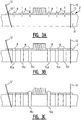
- Figure 2 shows a further set according to a further embodiment of the invention.
- one implant 1 is provided and three accessories are provided, i.e. accessory 2A, 2B and 2C.
- Each of the accessories 2A, 2B, 2C is provided here for an osteotomy of a different distance.
- Accessory 2A can thus be provided so as to perform an osteotomy of 3 mm
- 2B can be provided so as to perform an osteotomy of 5 mm
- accessory 2C is provided so as to perform an osteotomy of a distance of 7 mm.
- an accessory can be provided for any distance and that the above stated distances are only examples.
- Each of the accessories 2A, 2B, 2C has the same shape here as the one implant 1.
- the set according to the invention does however allow possible choices.
- the different distances are implemented in the respective accessories, on the one hand by positioning guides 10 at a different distance from each other and also by modifying the distance between first segment 5 and third segment 7 (relative to a corresponding distance in the implant) to the distance between guides 10.
- Figure 3 shows the method for performing an osteotomy of a predetermined distance making use of the set according to the invention.
- Explained here in the description of figure 3 is a medical method, although advantages and effects of the set according to the invention are also explained. This is because several of these advantages and effects are a direct result of technical choices made in the set according to the invention.
- the method for performing an osteotomy begins of course with making an incision into the body part where the osteotomy is to be performed (for instance the lower arm in the case an ulnar shortening is performed), and exposing the bone which has to be shortened.
- the surgeon determines here the distance by which a bone has to be shortened.
- An accessory from the set according to the invention can be selected subject to this determined distance (see figure 2 and associated description).
- FIG 3A shows how the selected accessory 2 is positioned relative to bone 11.
- Kirschner wires 12 can be used in the positioning of accessory 2 relative to bone 11.
- Kirschner wires 12 are generally known in surgery for positioning accessories and/or implants relative to the bone. Kirschner wires are also used to secure different bone parts relative to each other.
- Accessory 2 can for this purpose comprise Kirschner wire openings 13.
- At least one Kirschner wire opening 13 is preferably provided in each of the first segment 5 and third segment 7.
- a plurality of Kirschner wire openings 13 are more preferably provided in each of the first segment 5 and third segment 7.
- the implant can have corresponding Kirschner wire openings here, although this is not essential in the broadest embodiment of the invention.
- Kirschner wire openings 13 of accessory and implant correspond, the more use can be made of positioning and fixation by means of the Kirschner wires.
- Kirschner wire openings 13 are provided in accessory 2
- corresponding Kirschner wire openings 14 are preferably provided in the implant (see figure 3F ).
- the Kirschner wire openings 14 in implant 1 are then positioned relative to threaded holes 9 in the same way as Kirschner wire openings 13 in accessory 2 which are positioned relative to the first and second holes 8.
- each screw is drilled in the bone for each of the openings 8
- three proximal holes 15a, 15b and 15c are drilled, and three further distal holes 15d, 15e and 15f are drilled.
- the length of each screw must be precisely determined for the purpose of securing accessory 2 and/or implant 1 relative to the bone. This is generally known in surgery and has to do with material properties of bone (which is typically soft on the inside and hard at the position of the outer shell).
- the length of the screw depends on the thickness of accessory 2 and/or implant 1 at the position of the hole and on the length of the hole through the bone. Because accessory 2 has the same shape as implant 1 at least at the position of holes 8, the lengths of the screws which will be used at the end of the medical method to secure implant 1 relative to the bone can already be determined via the accessory when bone 11 has not yet been sawn through. Screw lengths can hereby be exactly determined more easily, and fewer complications will occur during securing of implant 1. This is because, since the bone has not yet been sawn through, the fixation of accessory 2 relative to bone 11 is precise and relatively strong. This makes it possible to determine the screw lengths in simple manner.
- accessory 2 is screwed at least partially to the bone. In figure 3C this is done by placing the screws which are adjacent to second segment 6. In the example of figure 3C these are screws 16c and 16d. The lengths of these screws were determined in the previous step. Because in the example of figure 3 accessory 2 has been further fixed to bone 11 using Kirschner wires 12, accessory 2 is screwed sufficiently firmly to bone 11 by means of screws 16c and 16d. The lengths of screws 16a, 16b, 16e and 16f can optionally be determined once screws 16c and 16d have been secured. It will be apparent from the above description that the method can be performed in different ways and with different sequence of steps, and that this step is only an example.
- the effective osteotomy is performed. Specifically, a saw blade 17 is moved in each of the guides 10 in order to saw through bone 11. Two saw cuts 19 and 20 are obtained via the two guides 10 of accessory 2. The bone segment 18 extending between the two saw cuts 19 and 20 is removed. Because saw 17 is guided in guides 10 while sawing through bone 11, saw cuts 19 and 20 are neatly parallel to each other. This allows the bone parts which thus result after shortening to connect closely together so that a speedy recovery of the bone can take place. In the example of figure 3 guides 10 are placed at an angle relative to bone 11, while in the examples of figures 1 and 2 the guides were positioned perpendicularly relative to bone 11.
- the saw cuts can alternatively be partially made, wherein the partially made saw cuts are completed after removal of the accessory. Since they have been partially made, the same direction can be followed accurately.
- Kirschner wires 12 form a manipulating mechanism for the surgeon for the purpose of manipulating the bone parts. Forceps can for instance thus be placed over the Kirschner wires 12 in order to pull the bone parts toward each other. Kirschner wires 12 can alternatively be manipulated manually. As further alternative, no or more than two K-wires can remain in situ, depending on the implant that will be used. It can also be an option to place a separate clamp on one or more K-wires after sliding of the implant over the K-wires in order to thus hold the implant pressed against the bone and to make the construction more stable so as to facilitate insertion of the screws.
- implant 1 can be placed relative to bone 11.
- the implant has Kirschner wire openings 14. This has the advantage that, when implant 1 is placed with the Kirschner wires 12 through openings 14, the bone parts of bone 11 are automatically positioned correctly relative to each other. This means that saw cuts 19 and 20 come to lie against each other. In this position the holes formed in the bone will be aligned with threaded holes 9 of implant 1.
- the screws for securing the implant (screws 16a-16f) have also already been selected. This means that the surgeon need neither drill any more holes in bone 11 nor perform any measurements after positioning of implant 1. The surgeon can immediately begin securing the screws (which have already been selected) in the corresponding holes. Implant 1 can thus be secured relative to bone 11 in order to fix the bone parts relative to each other.
- This implant 1 can be a standard osteosynthesis plate. No markings for sawing of a predetermined distance need be provided on implant 1 (these are in the second segment of the accessory). Nor need channels in which screws can be secured at different positions be provided in implant 1, since the positions of the drilled holes correspond directly to the positions of the holes in implant 1 (owing to the specific construction of the accessory).
- a further advantage of the invention worthy of mention is that the implant need not be clamped fixedly relative to the bone with clamps in order to be able to determine the screw lengths. Via the accessory of the invention the screw lengths can already be determined by means of the accessory.
Landscapes
- Health & Medical Sciences (AREA)
- Orthopedic Medicine & Surgery (AREA)
- Surgery (AREA)
- Life Sciences & Earth Sciences (AREA)
- Heart & Thoracic Surgery (AREA)
- Veterinary Medicine (AREA)
- Engineering & Computer Science (AREA)
- Biomedical Technology (AREA)
- Nuclear Medicine, Radiotherapy & Molecular Imaging (AREA)
- Medical Informatics (AREA)
- Molecular Biology (AREA)
- Animal Behavior & Ethology (AREA)
- General Health & Medical Sciences (AREA)
- Public Health (AREA)
- Dentistry (AREA)
- Oral & Maxillofacial Surgery (AREA)
- Neurology (AREA)
- Surgical Instruments (AREA)
Claims (10)
- Ensemble approprié pour être utilisé dans une ostéotomie de raccourcissement d'os d'une distance prédéfinie, l'ensemble comprenant :un implant (1) avec un segment distal (4) et un segment proximal (3), le segment distal comprenant au moins deux trous filetés distaux (8) et le segment proximal comprenant au moins deux trous filetés proximaux (8) ;une pluralité d'accessoires (2),chaque accessoire étant conçu pour être utilisé dans une ostéotomie de raccourcissement d'os d'une distance différente prédéfinie (d), et chaque accessoire (2) comprenant successivement un premier segment (5), un deuxième segment (6) et un troisième segment (7) ;le premier segment (5) comprenant des premiers trous filetés (9), le troisième segment (7) comprenant des seconds trous filetés (9), et le deuxième segment (6) comprenant deux guides (10) qui sont chacun conçus pour guider une lame de scie de sorte que l'ostéotomie de raccourcissement d'os de la distance prédéfinie (d) puisse être effectuée par l'intermédiaire des deux guides (10) ;les premiers trous filetés (9) et les seconds trous filetés (9) correspondant respectivement aux au moins deux trous filetés distaux (8) et aux au moins deux trous filetés proximaux (8), avec un espacement intermédiaire entre les premier et second trous filetés qui est égal à la somme de la distance prédéfinie (d) et un espacement intermédiaire correspondant entre les trous filetés distaux et proximaux (8) ; et,le premier segment (5) et le troisième segment (7) ayant la même forme, au moins à la position des trous filetés (9), comme respectivement le segment distal (4) et le segment proximal (3).
- Ensemble selon la revendication 1, le premier segment entier (5) ayant la même forme que le segment distal (4), et le troisième segment entier (7) ayant la même forme que le segment proximal (3).
- Ensemble selon la revendication 1 ou 2, l'expression « ayant la même forme » étant en outre spécifiée comme ayant sensiblement la même épaisseur.
- Ensemble selon l'une quelconque des revendications précédentes, l'expression « ayant la même forme » étant en outre spécifiée comme ayant une surface extérieure de la même forme.
- Ensemble selon l'une quelconque des revendications précédentes, le terme « correspondant » étant spécifié comme ayant une position relative l'un par rapport à l'autre qui est la même.
- Ensemble selon l'une quelconque des revendications précédentes, chaque guide (10) étant formé comme un canal essentiellement défini par deux surfaces qui s'étendent parallèlement et dans lequel la lame de scie peut se déplacer afin d'être guidée ainsi dans une position de sciage et dans une direction de sciage.
- Ensemble selon l'une quelconque des revendications précédentes, le segment distal (4) et le segment proximal (3) comprenant chacun une ouverture (13) pour une broche de Kirschner (12), et lequel le premier segment (5) et le troisième segment (7) comprenant chacun une ouverture correspondante.
- Ensemble selon l'une quelconque des revendications précédentes, l'ensemble étant approprié pour être utilisé dans une ostéotomie de raccourcissement d'os d'une première distance prédéfinie (d1) et étant approprié pour être utilisé dans une ostéotomie de raccourcissement d'os d'une seconde distance prédéfinie (d2), l'ensemble comprenant un autre accessoire (2) formé de manière similaire audit accessoire (2) et ledit accessoire (2) étant conçu pour la première distance prédéfinie (d1) et l'autre accessoire (2) étant conçu pour la seconde distance prédéfinie (d2).
- Ensemble selon l'une quelconque des revendications précédentes, la pluralité de distances prédéfinies (d1, d2) de la pluralité d'accessoires (2) pouvant peut être fournie en positionnant les deux guides (10) à une distance différente (d1, d2) les uns des autres.
- Ensemble selon l'une quelconque des revendications 1 à 8, la pluralité de distances prédéfinies (d1, d2) de la pluralité d'accessoires (2) pouvant être fournie en modifiant une distance entre le premier segment (5) et le troisième segment (7).
Applications Claiming Priority (2)
| Application Number | Priority Date | Filing Date | Title |
|---|---|---|---|
| BE2014/0125A BE1021823B1 (nl) | 2014-02-26 | 2014-02-26 | Hulpstuk voor osteotomie |
| PCT/BE2015/000004 WO2015127515A2 (fr) | 2014-02-26 | 2015-02-16 | Accessoire pour ostéotomie |
Publications (2)
| Publication Number | Publication Date |
|---|---|
| EP3113695A2 EP3113695A2 (fr) | 2017-01-11 |
| EP3113695B1 true EP3113695B1 (fr) | 2019-03-20 |
Family
ID=50624340
Family Applications (1)
| Application Number | Title | Priority Date | Filing Date |
|---|---|---|---|
| EP15723822.1A Active EP3113695B1 (fr) | 2014-02-26 | 2015-02-16 | Ensemble de guidage pour ostéotomie |
Country Status (9)
| Country | Link |
|---|---|
| US (1) | US10390840B2 (fr) |
| EP (1) | EP3113695B1 (fr) |
| JP (1) | JP6445579B2 (fr) |
| CN (1) | CN106132320A (fr) |
| AU (1) | AU2015222700B2 (fr) |
| BE (1) | BE1021823B1 (fr) |
| CA (1) | CA2940580C (fr) |
| ES (1) | ES2718951T3 (fr) |
| WO (1) | WO2015127515A2 (fr) |
Families Citing this family (24)
| Publication number | Priority date | Publication date | Assignee | Title |
|---|---|---|---|---|
| BE1021823B1 (nl) | 2014-02-26 | 2016-01-20 | Biomet Manufacturing, Llc | Hulpstuk voor osteotomie |
| US20160015426A1 (en) | 2014-07-15 | 2016-01-21 | Treace Medical Concepts, Inc. | Bone positioning and cutting system and method |
| US9687250B2 (en) | 2015-01-07 | 2017-06-27 | Treace Medical Concepts, Inc. | Bone cutting guide systems and methods |
| WO2016134154A1 (fr) | 2015-02-18 | 2016-08-25 | Treace Medical Concepts, Inc. | Guide de coupe d'os pivotant utile pour le réalignement d'os et les techniques de compression |
| US10653467B2 (en) | 2015-05-06 | 2020-05-19 | Treace Medical Concepts, Inc. | Intra-osseous plate system and method |
| US9622805B2 (en) | 2015-08-14 | 2017-04-18 | Treace Medical Concepts, Inc. | Bone positioning and preparing guide systems and methods |
| US10849663B2 (en) | 2015-07-14 | 2020-12-01 | Treace Medical Concepts, Inc. | Bone cutting guide systems and methods |
| JP6985248B2 (ja) | 2015-07-14 | 2021-12-22 | トリース メディカル コンセプツ,インコーポレイティド | 骨位置付けガイド |
| EP3334356A4 (fr) | 2015-08-14 | 2019-05-15 | Treace Medical Concepts, Inc. | Procédure sur l'articulation tarso-métatarsienne utilisant un point d'appui |
| US11278337B2 (en) | 2015-08-14 | 2022-03-22 | Treace Medical Concepts, Inc. | Tarsal-metatarsal joint procedure utilizing fulcrum |
| JP6940488B2 (ja) | 2015-09-18 | 2021-09-29 | トリース メディカル コンセプツ,インコーポレイティド | 継手スペーサシステム及び方法 |
| US10512470B1 (en) | 2016-08-26 | 2019-12-24 | Treace Medical Concepts, Inc. | Osteotomy procedure for correcting bone misalignment |
| US10582936B1 (en) | 2016-11-11 | 2020-03-10 | Treace Medical Concepts, Inc. | Devices and techniques for performing an osteotomy procedure on a first metatarsal to correct a bone misalignment |
| US10939939B1 (en) | 2017-02-26 | 2021-03-09 | Treace Medical Concepts, Inc. | Fulcrum for tarsal-metatarsal joint procedure |
| EP3820387A4 (fr) | 2018-07-11 | 2022-07-06 | Treace Medical Concepts, Inc. | Compresseur-distracteur pour réalignement angulaire de parties osseuses |
| US11583323B2 (en) | 2018-07-12 | 2023-02-21 | Treace Medical Concepts, Inc. | Multi-diameter bone pin for installing and aligning bone fixation plate while minimizing bone damage |
| US11607250B2 (en) | 2019-02-13 | 2023-03-21 | Treace Medical Concepts, Inc. | Tarsal-metatarsal joint procedure utilizing compressor-distractor and instrument providing sliding surface |
| JP2022543478A (ja) | 2019-08-07 | 2022-10-12 | トリース メディカル コンセプツ,インコーポレイティド | 骨切断および関節再整列処置のための二平面器具 |
| US11889998B1 (en) | 2019-09-12 | 2024-02-06 | Treace Medical Concepts, Inc. | Surgical pin positioning lock |
| US11890039B1 (en) | 2019-09-13 | 2024-02-06 | Treace Medical Concepts, Inc. | Multi-diameter K-wire for orthopedic applications |
| US11986251B2 (en) | 2019-09-13 | 2024-05-21 | Treace Medical Concepts, Inc. | Patient-specific osteotomy instrumentation |
| AU2021212261A1 (en) | 2020-01-31 | 2022-08-18 | Treace Medical Concepts, Inc. | Metatarsophalangeal joint preparation and metatarsal realignment for fusion |
| US11457931B1 (en) | 2021-03-31 | 2022-10-04 | Avanti Orthopaedics Llc | Bone shortening osteotomy apparatus |
| USD1011524S1 (en) | 2022-02-23 | 2024-01-16 | Treace Medical Concepts, Inc. | Compressor-distractor for the foot |
Family Cites Families (21)
| Publication number | Priority date | Publication date | Assignee | Title |
|---|---|---|---|---|
| US4565191A (en) * | 1984-01-12 | 1986-01-21 | Slocum D Barclay | Apparatus and method for performing cuneiform osteotomy |
| JPS6445579A (en) | 1987-08-08 | 1989-02-20 | Hitachi Koki Kk | Air screw driver |
| US4929247A (en) * | 1988-10-06 | 1990-05-29 | Rayhack John M | Bone compression and distraction device |
| US5176685A (en) * | 1989-10-30 | 1993-01-05 | Rayhack John M | Precision bone cutting guide |
| US5042983A (en) * | 1989-10-30 | 1991-08-27 | Rayhack John M | Precision bone cutting guide |
| US6007535A (en) * | 1996-01-03 | 1999-12-28 | John M. Rayhack | Multi-plane bone distraction system |
| JP3041355B2 (ja) * | 1996-11-08 | 2000-05-15 | 隆也 水関 | 骨切り鋸案内具 |
| GB2334214B (en) * | 1998-02-12 | 2003-01-22 | John Knowles Stanley | Cutting guide |
| US6206882B1 (en) * | 1999-03-30 | 2001-03-27 | Surgical Dynamics Inc. | Plating system for the spine |
| US8652142B2 (en) * | 2006-04-28 | 2014-02-18 | Acumed Llc | Osteotomy systems |
| US7540874B2 (en) * | 2004-05-27 | 2009-06-02 | Trimed Inc. | Method and device for use in osteotomy |
| US20070276383A1 (en) * | 2006-05-11 | 2007-11-29 | Rayhack L.L.C. | Osteotomy system |
| WO2009146135A2 (fr) * | 2008-04-04 | 2009-12-03 | Skeletal Dynamics Llc | Système d’ostéotomie par compression/distraction, plaque, procédé, guide-foret et guide-scie |
| US20100168799A1 (en) * | 2008-12-29 | 2010-07-01 | Schumer Evan D | Ulnar osteotomy plate including increased compression |
| BR112012021877B1 (pt) * | 2010-03-04 | 2020-05-26 | Synthes Gmbh | Sistema para osteotomia da ulna |
| CN102753109A (zh) | 2010-11-11 | 2012-10-24 | 厄尔西奥·米盖尔·内马 | 用于骨切开术的多重可调板 |
| WO2013156545A1 (fr) * | 2012-04-18 | 2013-10-24 | Materialise N.V. | Systèmes et procédés de fixation d'os orthopédiques |
| ES2687521T3 (es) * | 2012-09-12 | 2018-10-25 | Nextremity Solutions, Inc. | Dispositivo de acortamiento de huesos |
| BE1021823B1 (nl) | 2014-02-26 | 2016-01-20 | Biomet Manufacturing, Llc | Hulpstuk voor osteotomie |
| GB2530247B (en) * | 2014-07-29 | 2020-12-30 | Orthomed Uk Ltd | A surgical apparatus |
| WO2016134160A1 (fr) * | 2015-02-18 | 2016-08-25 | Treace Medical Concepts, Inc. | Nécessaire de plaque osseuse pour applications de pied et de cheville |
-
2014
- 2014-02-26 BE BE2014/0125A patent/BE1021823B1/nl not_active IP Right Cessation
-
2015
- 2015-02-16 AU AU2015222700A patent/AU2015222700B2/en active Active
- 2015-02-16 EP EP15723822.1A patent/EP3113695B1/fr active Active
- 2015-02-16 CA CA2940580A patent/CA2940580C/fr active Active
- 2015-02-16 WO PCT/BE2015/000004 patent/WO2015127515A2/fr active Application Filing
- 2015-02-16 US US15/116,427 patent/US10390840B2/en active Active
- 2015-02-16 CN CN201580016647.6A patent/CN106132320A/zh active Pending
- 2015-02-16 JP JP2016554219A patent/JP6445579B2/ja active Active
- 2015-02-16 ES ES15723822T patent/ES2718951T3/es active Active
Non-Patent Citations (1)
| Title |
|---|
| None * |
Also Published As
| Publication number | Publication date |
|---|---|
| BE1021823B1 (nl) | 2016-01-20 |
| AU2015222700A1 (en) | 2016-10-13 |
| EP3113695A2 (fr) | 2017-01-11 |
| WO2015127515A3 (fr) | 2015-10-15 |
| US10390840B2 (en) | 2019-08-27 |
| CN106132320A (zh) | 2016-11-16 |
| AU2015222700B2 (en) | 2018-12-20 |
| ES2718951T3 (es) | 2019-07-05 |
| US20170007267A1 (en) | 2017-01-12 |
| JP2017510332A (ja) | 2017-04-13 |
| WO2015127515A2 (fr) | 2015-09-03 |
| JP6445579B2 (ja) | 2018-12-26 |
| CA2940580C (fr) | 2019-10-29 |
| CA2940580A1 (fr) | 2015-09-03 |
Similar Documents
| Publication | Publication Date | Title |
|---|---|---|
| EP3113695B1 (fr) | Ensemble de guidage pour ostéotomie | |
| US7972338B2 (en) | Self-supporting osteotomy guide and retraction device and method of use | |
| US10349990B2 (en) | Method and device for attaching a bone plate | |
| US7540874B2 (en) | Method and device for use in osteotomy | |
| US10786291B2 (en) | Proximal bunion resection guides and plates and methods of use | |
| EP2976024B1 (fr) | Dispositif chirurgical pour orientation correcte pendant une ostéotomie | |
| EP2670327B1 (fr) | Dispositif de réparation de défaut osseux | |
| CA2625634C (fr) | Dispositif de visee | |
| US20050273112A1 (en) | Three-dimensional osteotomy device and method for treating bone deformities | |
| US20210259716A1 (en) | Chevron osteotomy tools and methods | |
| JP2007515990A (ja) | 手術中にねじ切りされる開口部を備えた骨プレート | |
| JP2006506197A (ja) | 調節可能な骨プレート | |
| JP2021532845A (ja) | 経皮ターゲティングデバイス | |
| CN112638295B (zh) | 改变骨构型的方法和系统 | |
| RU184952U1 (ru) | Устройство для клиновидной укорачивающей остеотомии длинных трубчатых костей | |
| RU2684528C2 (ru) | Способ интрамедуллярной фиксации кости и направляющий инструмент для прецизионного совмещения осей симметрии направителей инструмента с осями симметрии отверстий интрамедуллярного стержня |
Legal Events
| Date | Code | Title | Description |
|---|---|---|---|
| STAA | Information on the status of an ep patent application or granted ep patent |
Free format text: STATUS: THE INTERNATIONAL PUBLICATION HAS BEEN MADE |
|
| PUAI | Public reference made under article 153(3) epc to a published international application that has entered the european phase |
Free format text: ORIGINAL CODE: 0009012 |
|
| STAA | Information on the status of an ep patent application or granted ep patent |
Free format text: STATUS: REQUEST FOR EXAMINATION WAS MADE |
|
| 17P | Request for examination filed |
Effective date: 20160926 |
|
| AK | Designated contracting states |
Kind code of ref document: A2 Designated state(s): AL AT BE BG CH CY CZ DE DK EE ES FI FR GB GR HR HU IE IS IT LI LT LU LV MC MK MT NL NO PL PT RO RS SE SI SK SM TR |
|
| AX | Request for extension of the european patent |
Extension state: BA ME |
|
| DAX | Request for extension of the european patent (deleted) | ||
| RAP1 | Party data changed (applicant data changed or rights of an application transferred) |
Owner name: BIOMET MANUFACTURING, LLC |
|
| GRAP | Despatch of communication of intention to grant a patent |
Free format text: ORIGINAL CODE: EPIDOSNIGR1 |
|
| STAA | Information on the status of an ep patent application or granted ep patent |
Free format text: STATUS: GRANT OF PATENT IS INTENDED |
|
| INTG | Intention to grant announced |
Effective date: 20180905 |
|
| GRAS | Grant fee paid |
Free format text: ORIGINAL CODE: EPIDOSNIGR3 |
|
| GRAA | (expected) grant |
Free format text: ORIGINAL CODE: 0009210 |
|
| STAA | Information on the status of an ep patent application or granted ep patent |
Free format text: STATUS: THE PATENT HAS BEEN GRANTED |
|
| AK | Designated contracting states |
Kind code of ref document: B1 Designated state(s): AL AT BE BG CH CY CZ DE DK EE ES FI FR GB GR HR HU IE IS IT LI LT LU LV MC MK MT NL NO PL PT RO RS SE SI SK SM TR |
|
| REG | Reference to a national code |
Ref country code: GB Ref legal event code: FG4D |
|
| REG | Reference to a national code |
Ref country code: CH Ref legal event code: EP Ref country code: CH Ref legal event code: NV Representative=s name: MICHELI AND CIE SA, CH |
|
| REG | Reference to a national code |
Ref country code: DE Ref legal event code: R096 Ref document number: 602015026722 Country of ref document: DE |
|
| REG | Reference to a national code |
Ref country code: AT Ref legal event code: REF Ref document number: 1109665 Country of ref document: AT Kind code of ref document: T Effective date: 20190415 |
|
| REG | Reference to a national code |
Ref country code: IE Ref legal event code: FG4D |
|
| REG | Reference to a national code |
Ref country code: ES Ref legal event code: FG2A Ref document number: 2718951 Country of ref document: ES Kind code of ref document: T3 Effective date: 20190705 |
|
| REG | Reference to a national code |
Ref country code: NL Ref legal event code: MP Effective date: 20190320 |
|
| PG25 | Lapsed in a contracting state [announced via postgrant information from national office to epo] |
Ref country code: SE Free format text: LAPSE BECAUSE OF FAILURE TO SUBMIT A TRANSLATION OF THE DESCRIPTION OR TO PAY THE FEE WITHIN THE PRESCRIBED TIME-LIMIT Effective date: 20190320 Ref country code: FI Free format text: LAPSE BECAUSE OF FAILURE TO SUBMIT A TRANSLATION OF THE DESCRIPTION OR TO PAY THE FEE WITHIN THE PRESCRIBED TIME-LIMIT Effective date: 20190320 Ref country code: NO Free format text: LAPSE BECAUSE OF FAILURE TO SUBMIT A TRANSLATION OF THE DESCRIPTION OR TO PAY THE FEE WITHIN THE PRESCRIBED TIME-LIMIT Effective date: 20190620 Ref country code: LT Free format text: LAPSE BECAUSE OF FAILURE TO SUBMIT A TRANSLATION OF THE DESCRIPTION OR TO PAY THE FEE WITHIN THE PRESCRIBED TIME-LIMIT Effective date: 20190320 |
|
| REG | Reference to a national code |
Ref country code: LT Ref legal event code: MG4D |
|
| PG25 | Lapsed in a contracting state [announced via postgrant information from national office to epo] |
Ref country code: GR Free format text: LAPSE BECAUSE OF FAILURE TO SUBMIT A TRANSLATION OF THE DESCRIPTION OR TO PAY THE FEE WITHIN THE PRESCRIBED TIME-LIMIT Effective date: 20190621 Ref country code: NL Free format text: LAPSE BECAUSE OF FAILURE TO SUBMIT A TRANSLATION OF THE DESCRIPTION OR TO PAY THE FEE WITHIN THE PRESCRIBED TIME-LIMIT Effective date: 20190320 Ref country code: HR Free format text: LAPSE BECAUSE OF FAILURE TO SUBMIT A TRANSLATION OF THE DESCRIPTION OR TO PAY THE FEE WITHIN THE PRESCRIBED TIME-LIMIT Effective date: 20190320 Ref country code: LV Free format text: LAPSE BECAUSE OF FAILURE TO SUBMIT A TRANSLATION OF THE DESCRIPTION OR TO PAY THE FEE WITHIN THE PRESCRIBED TIME-LIMIT Effective date: 20190320 Ref country code: RS Free format text: LAPSE BECAUSE OF FAILURE TO SUBMIT A TRANSLATION OF THE DESCRIPTION OR TO PAY THE FEE WITHIN THE PRESCRIBED TIME-LIMIT Effective date: 20190320 Ref country code: BG Free format text: LAPSE BECAUSE OF FAILURE TO SUBMIT A TRANSLATION OF THE DESCRIPTION OR TO PAY THE FEE WITHIN THE PRESCRIBED TIME-LIMIT Effective date: 20190620 |
|
| REG | Reference to a national code |
Ref country code: AT Ref legal event code: MK05 Ref document number: 1109665 Country of ref document: AT Kind code of ref document: T Effective date: 20190320 |
|
| PG25 | Lapsed in a contracting state [announced via postgrant information from national office to epo] |
Ref country code: SK Free format text: LAPSE BECAUSE OF FAILURE TO SUBMIT A TRANSLATION OF THE DESCRIPTION OR TO PAY THE FEE WITHIN THE PRESCRIBED TIME-LIMIT Effective date: 20190320 Ref country code: RO Free format text: LAPSE BECAUSE OF FAILURE TO SUBMIT A TRANSLATION OF THE DESCRIPTION OR TO PAY THE FEE WITHIN THE PRESCRIBED TIME-LIMIT Effective date: 20190320 Ref country code: CZ Free format text: LAPSE BECAUSE OF FAILURE TO SUBMIT A TRANSLATION OF THE DESCRIPTION OR TO PAY THE FEE WITHIN THE PRESCRIBED TIME-LIMIT Effective date: 20190320 Ref country code: EE Free format text: LAPSE BECAUSE OF FAILURE TO SUBMIT A TRANSLATION OF THE DESCRIPTION OR TO PAY THE FEE WITHIN THE PRESCRIBED TIME-LIMIT Effective date: 20190320 Ref country code: AL Free format text: LAPSE BECAUSE OF FAILURE TO SUBMIT A TRANSLATION OF THE DESCRIPTION OR TO PAY THE FEE WITHIN THE PRESCRIBED TIME-LIMIT Effective date: 20190320 Ref country code: PT Free format text: LAPSE BECAUSE OF FAILURE TO SUBMIT A TRANSLATION OF THE DESCRIPTION OR TO PAY THE FEE WITHIN THE PRESCRIBED TIME-LIMIT Effective date: 20190720 |
|
| PG25 | Lapsed in a contracting state [announced via postgrant information from national office to epo] |
Ref country code: PL Free format text: LAPSE BECAUSE OF FAILURE TO SUBMIT A TRANSLATION OF THE DESCRIPTION OR TO PAY THE FEE WITHIN THE PRESCRIBED TIME-LIMIT Effective date: 20190320 Ref country code: SM Free format text: LAPSE BECAUSE OF FAILURE TO SUBMIT A TRANSLATION OF THE DESCRIPTION OR TO PAY THE FEE WITHIN THE PRESCRIBED TIME-LIMIT Effective date: 20190320 |
|
| PG25 | Lapsed in a contracting state [announced via postgrant information from national office to epo] |
Ref country code: AT Free format text: LAPSE BECAUSE OF FAILURE TO SUBMIT A TRANSLATION OF THE DESCRIPTION OR TO PAY THE FEE WITHIN THE PRESCRIBED TIME-LIMIT Effective date: 20190320 Ref country code: IS Free format text: LAPSE BECAUSE OF FAILURE TO SUBMIT A TRANSLATION OF THE DESCRIPTION OR TO PAY THE FEE WITHIN THE PRESCRIBED TIME-LIMIT Effective date: 20190720 |
|
| REG | Reference to a national code |
Ref country code: DE Ref legal event code: R097 Ref document number: 602015026722 Country of ref document: DE |
|
| REG | Reference to a national code |
Ref country code: DE Ref legal event code: R081 Ref document number: 602015026722 Country of ref document: DE Owner name: STRYKER EUROPEAN OPERATIONS LIMITED, CARRIGTWO, IE Free format text: FORMER OWNER: BIOMET MANUFACTURING, LLC, WARSAW, IN, US Ref country code: DE Ref legal event code: R082 Ref document number: 602015026722 Country of ref document: DE Representative=s name: VENNER SHIPLEY LLP, CAMBRIDGE, GB Ref country code: DE Ref legal event code: R081 Ref document number: 602015026722 Country of ref document: DE Owner name: VERSTREKEN, FREDERIK, BE Free format text: FORMER OWNER: BIOMET MANUFACTURING, LLC, WARSAW, IND., US Ref country code: DE Ref legal event code: R082 Ref document number: 602015026722 Country of ref document: DE Representative=s name: VENNER SHIPLEY LLP, DE Ref country code: DE Ref legal event code: R081 Ref document number: 602015026722 Country of ref document: DE Owner name: VERSTREKEN, FREDERIK, BE Free format text: FORMER OWNER: BIOMET MANUFACTURING, LLC, WARSAW, IN, US Ref country code: DE Ref legal event code: R081 Ref document number: 602015026722 Country of ref document: DE Owner name: ARTHREX INC., NAPLES, US Free format text: FORMER OWNER: BIOMET MANUFACTURING, LLC, WARSAW, IN, US |
|
| PLBE | No opposition filed within time limit |
Free format text: ORIGINAL CODE: 0009261 |
|
| STAA | Information on the status of an ep patent application or granted ep patent |
Free format text: STATUS: NO OPPOSITION FILED WITHIN TIME LIMIT |
|
| PG25 | Lapsed in a contracting state [announced via postgrant information from national office to epo] |
Ref country code: DK Free format text: LAPSE BECAUSE OF FAILURE TO SUBMIT A TRANSLATION OF THE DESCRIPTION OR TO PAY THE FEE WITHIN THE PRESCRIBED TIME-LIMIT Effective date: 20190320 |
|
| REG | Reference to a national code |
Ref country code: GB Ref legal event code: 732E Free format text: REGISTERED BETWEEN 20200116 AND 20200122 |
|
| 26N | No opposition filed |
Effective date: 20200102 |
|
| PG25 | Lapsed in a contracting state [announced via postgrant information from national office to epo] |
Ref country code: SI Free format text: LAPSE BECAUSE OF FAILURE TO SUBMIT A TRANSLATION OF THE DESCRIPTION OR TO PAY THE FEE WITHIN THE PRESCRIBED TIME-LIMIT Effective date: 20190320 |
|
| PG25 | Lapsed in a contracting state [announced via postgrant information from national office to epo] |
Ref country code: TR Free format text: LAPSE BECAUSE OF FAILURE TO SUBMIT A TRANSLATION OF THE DESCRIPTION OR TO PAY THE FEE WITHIN THE PRESCRIBED TIME-LIMIT Effective date: 20190320 |
|
| REG | Reference to a national code |
Ref country code: ES Ref legal event code: PC2A Owner name: DR. FREDERIK VERSTREKEN Effective date: 20200326 |
|
| PGFP | Annual fee paid to national office [announced via postgrant information from national office to epo] |
Ref country code: ES Payment date: 20200323 Year of fee payment: 6 |
|
| REG | Reference to a national code |
Ref country code: BE Ref legal event code: PD Owner name: VERSTREKEN, FREDERIK; BE Free format text: DETAILS ASSIGNMENT: CHANGE OF OWNER(S), CESSION; FORMER OWNER NAME: BIOMET MANUFACTURING, LLC Effective date: 20200430 |
|
| REG | Reference to a national code |
Ref country code: DE Ref legal event code: R082 Ref document number: 602015026722 Country of ref document: DE Representative=s name: VENNER SHIPLEY GERMANY LLP, DE Ref country code: DE Ref legal event code: R082 Ref document number: 602015026722 Country of ref document: DE Representative=s name: WUESTHOFF & WUESTHOFF PATENTANWAELTE UND RECHT, DE Ref country code: DE Ref legal event code: R082 Ref document number: 602015026722 Country of ref document: DE Representative=s name: VENNER SHIPLEY LLP, DE |
|
| PG25 | Lapsed in a contracting state [announced via postgrant information from national office to epo] |
Ref country code: LU Free format text: LAPSE BECAUSE OF NON-PAYMENT OF DUE FEES Effective date: 20200216 Ref country code: MC Free format text: LAPSE BECAUSE OF FAILURE TO SUBMIT A TRANSLATION OF THE DESCRIPTION OR TO PAY THE FEE WITHIN THE PRESCRIBED TIME-LIMIT Effective date: 20190320 |
|
| REG | Reference to a national code |
Ref country code: DE Ref legal event code: R081 Ref document number: 602015026722 Country of ref document: DE Owner name: STRYKER EUROPEAN OPERATIONS LIMITED, CARRIGTWO, IE Free format text: FORMER OWNER: VERSTREKEN, FREDERIK, SCHOTEN, BE Ref country code: DE Ref legal event code: R081 Ref document number: 602015026722 Country of ref document: DE Owner name: VERSTREKEN, FREDERIK, BE Free format text: FORMER OWNER: VERSTREKEN, FREDERIK, SCHOTEN, BE Ref country code: DE Ref legal event code: R082 Ref document number: 602015026722 Country of ref document: DE Representative=s name: VENNER SHIPLEY LLP, DE Ref country code: DE Ref legal event code: R081 Ref document number: 602015026722 Country of ref document: DE Owner name: ARTHREX INC., NAPLES, US Free format text: FORMER OWNER: VERSTREKEN, FREDERIK, SCHOTEN, BE |
|
| PGFP | Annual fee paid to national office [announced via postgrant information from national office to epo] |
Ref country code: IT Payment date: 20210112 Year of fee payment: 7 |
|
| REG | Reference to a national code |
Ref country code: BE Ref legal event code: PD Owner name: ARTHREX, INC.; US Free format text: DETAILS ASSIGNMENT: CHANGE OF OWNER(S), ASSIGNMENT; FORMER OWNER NAME: VERSTREKEN, FREDERIK Effective date: 20210420 |
|
| REG | Reference to a national code |
Ref country code: GB Ref legal event code: 732E Free format text: REGISTERED BETWEEN 20210624 AND 20210630 |
|
| REG | Reference to a national code |
Ref country code: ES Ref legal event code: FD2A Effective date: 20220511 |
|
| PG25 | Lapsed in a contracting state [announced via postgrant information from national office to epo] |
Ref country code: MT Free format text: LAPSE BECAUSE OF FAILURE TO SUBMIT A TRANSLATION OF THE DESCRIPTION OR TO PAY THE FEE WITHIN THE PRESCRIBED TIME-LIMIT Effective date: 20190320 Ref country code: CY Free format text: LAPSE BECAUSE OF FAILURE TO SUBMIT A TRANSLATION OF THE DESCRIPTION OR TO PAY THE FEE WITHIN THE PRESCRIBED TIME-LIMIT Effective date: 20190320 |
|
| PG25 | Lapsed in a contracting state [announced via postgrant information from national office to epo] |
Ref country code: MK Free format text: LAPSE BECAUSE OF FAILURE TO SUBMIT A TRANSLATION OF THE DESCRIPTION OR TO PAY THE FEE WITHIN THE PRESCRIBED TIME-LIMIT Effective date: 20190320 |
|
| PG25 | Lapsed in a contracting state [announced via postgrant information from national office to epo] |
Ref country code: ES Free format text: LAPSE BECAUSE OF NON-PAYMENT OF DUE FEES Effective date: 20210217 |
|
| PG25 | Lapsed in a contracting state [announced via postgrant information from national office to epo] |
Ref country code: IT Free format text: LAPSE BECAUSE OF NON-PAYMENT OF DUE FEES Effective date: 20220216 |
|
| PGFP | Annual fee paid to national office [announced via postgrant information from national office to epo] |
Ref country code: BE Payment date: 20230117 Year of fee payment: 9 |
|
| REG | Reference to a national code |
Ref country code: DE Ref legal event code: R081 Ref document number: 602015026722 Country of ref document: DE Owner name: STRYKER EUROPEAN OPERATIONS LIMITED, CARRIGTWO, IE Free format text: FORMER OWNER: ARTHREX INC., NAPLES, FL, US Ref country code: DE Ref legal event code: R081 Ref document number: 602015026722 Country of ref document: DE Owner name: VERSTREKEN, FREDERIK, BE Free format text: FORMER OWNER: ARTHREX INC., NAPLES, FL, US |
|
| REG | Reference to a national code |
Ref country code: BE Ref legal event code: PD Owner name: VERSTREKEN FREDERIK, MD; BE Free format text: DETAILS ASSIGNMENT: CHANGE OF OWNER(S), ASSIGNMENT; FORMER OWNER NAME: ARTHREX, INC. Effective date: 20231019 |
|
| REG | Reference to a national code |
Ref country code: GB Ref legal event code: 732E Free format text: REGISTERED BETWEEN 20231026 AND 20231101 |
|
| PGFP | Annual fee paid to national office [announced via postgrant information from national office to epo] |
Ref country code: IE Payment date: 20231211 Year of fee payment: 10 Ref country code: FR Payment date: 20231212 Year of fee payment: 10 |
|
| REG | Reference to a national code |
Ref country code: DE Ref legal event code: R082 Ref document number: 602015026722 Country of ref document: DE Representative=s name: WUESTHOFF & WUESTHOFF PATENTANWAELTE UND RECHT, DE |
|
| REG | Reference to a national code |
Ref country code: DE Ref legal event code: R081 Ref document number: 602015026722 Country of ref document: DE Owner name: STRYKER EUROPEAN OPERATIONS LIMITED, CARRIGTWO, IE Free format text: FORMER OWNER: VERSTREKEN, FREDERIK, SCHOTEN, BE |
|
| P01 | Opt-out of the competence of the unified patent court (upc) registered |
Effective date: 20240307 |
|
| PGFP | Annual fee paid to national office [announced via postgrant information from national office to epo] |
Ref country code: DE Payment date: 20231220 Year of fee payment: 10 Ref country code: CH Payment date: 20240301 Year of fee payment: 10 Ref country code: GB Payment date: 20240108 Year of fee payment: 10 |
|
| REG | Reference to a national code |
Ref country code: GB Ref legal event code: 732E Free format text: REGISTERED BETWEEN 20240425 AND 20240501 |