EP3113496A1 - Procédé et dispositif de codage d'une image hdr et d'une image sdr obtenus à partir de l'image hdr au moyen de fonctions de mappage de couleurs - Google Patents
Procédé et dispositif de codage d'une image hdr et d'une image sdr obtenus à partir de l'image hdr au moyen de fonctions de mappage de couleurs Download PDFInfo
- Publication number
- EP3113496A1 EP3113496A1 EP15306048.8A EP15306048A EP3113496A1 EP 3113496 A1 EP3113496 A1 EP 3113496A1 EP 15306048 A EP15306048 A EP 15306048A EP 3113496 A1 EP3113496 A1 EP 3113496A1
- Authority
- EP
- European Patent Office
- Prior art keywords
- picture
- hdr
- sdr
- decoded
- color
- Prior art date
- Legal status (The legal status is an assumption and is not a legal conclusion. Google has not performed a legal analysis and makes no representation as to the accuracy of the status listed.)
- Withdrawn
Links
Images


Classifications
-
- H—ELECTRICITY
- H04—ELECTRIC COMMUNICATION TECHNIQUE
- H04N—PICTORIAL COMMUNICATION, e.g. TELEVISION
- H04N19/00—Methods or arrangements for coding, decoding, compressing or decompressing digital video signals
- H04N19/10—Methods or arrangements for coding, decoding, compressing or decompressing digital video signals using adaptive coding
- H04N19/169—Methods or arrangements for coding, decoding, compressing or decompressing digital video signals using adaptive coding characterised by the coding unit, i.e. the structural portion or semantic portion of the video signal being the object or the subject of the adaptive coding
- H04N19/186—Methods or arrangements for coding, decoding, compressing or decompressing digital video signals using adaptive coding characterised by the coding unit, i.e. the structural portion or semantic portion of the video signal being the object or the subject of the adaptive coding the unit being a colour or a chrominance component
-
- H—ELECTRICITY
- H04—ELECTRIC COMMUNICATION TECHNIQUE
- H04N—PICTORIAL COMMUNICATION, e.g. TELEVISION
- H04N19/00—Methods or arrangements for coding, decoding, compressing or decompressing digital video signals
- H04N19/10—Methods or arrangements for coding, decoding, compressing or decompressing digital video signals using adaptive coding
- H04N19/102—Methods or arrangements for coding, decoding, compressing or decompressing digital video signals using adaptive coding characterised by the element, parameter or selection affected or controlled by the adaptive coding
- H04N19/124—Quantisation
-
- H—ELECTRICITY
- H04—ELECTRIC COMMUNICATION TECHNIQUE
- H04N—PICTORIAL COMMUNICATION, e.g. TELEVISION
- H04N19/00—Methods or arrangements for coding, decoding, compressing or decompressing digital video signals
- H04N19/10—Methods or arrangements for coding, decoding, compressing or decompressing digital video signals using adaptive coding
- H04N19/169—Methods or arrangements for coding, decoding, compressing or decompressing digital video signals using adaptive coding characterised by the coding unit, i.e. the structural portion or semantic portion of the video signal being the object or the subject of the adaptive coding
- H04N19/17—Methods or arrangements for coding, decoding, compressing or decompressing digital video signals using adaptive coding characterised by the coding unit, i.e. the structural portion or semantic portion of the video signal being the object or the subject of the adaptive coding the unit being an image region, e.g. an object
- H04N19/172—Methods or arrangements for coding, decoding, compressing or decompressing digital video signals using adaptive coding characterised by the coding unit, i.e. the structural portion or semantic portion of the video signal being the object or the subject of the adaptive coding the unit being an image region, e.g. an object the region being a picture, frame or field
-
- H—ELECTRICITY
- H04—ELECTRIC COMMUNICATION TECHNIQUE
- H04N—PICTORIAL COMMUNICATION, e.g. TELEVISION
- H04N19/00—Methods or arrangements for coding, decoding, compressing or decompressing digital video signals
- H04N19/10—Methods or arrangements for coding, decoding, compressing or decompressing digital video signals using adaptive coding
- H04N19/169—Methods or arrangements for coding, decoding, compressing or decompressing digital video signals using adaptive coding characterised by the coding unit, i.e. the structural portion or semantic portion of the video signal being the object or the subject of the adaptive coding
- H04N19/182—Methods or arrangements for coding, decoding, compressing or decompressing digital video signals using adaptive coding characterised by the coding unit, i.e. the structural portion or semantic portion of the video signal being the object or the subject of the adaptive coding the unit being a pixel
-
- H—ELECTRICITY
- H04—ELECTRIC COMMUNICATION TECHNIQUE
- H04N—PICTORIAL COMMUNICATION, e.g. TELEVISION
- H04N19/00—Methods or arrangements for coding, decoding, compressing or decompressing digital video signals
- H04N19/30—Methods or arrangements for coding, decoding, compressing or decompressing digital video signals using hierarchical techniques, e.g. scalability
-
- H—ELECTRICITY
- H04—ELECTRIC COMMUNICATION TECHNIQUE
- H04N—PICTORIAL COMMUNICATION, e.g. TELEVISION
- H04N19/00—Methods or arrangements for coding, decoding, compressing or decompressing digital video signals
- H04N19/44—Decoders specially adapted therefor, e.g. video decoders which are asymmetric with respect to the encoder
-
- H—ELECTRICITY
- H04—ELECTRIC COMMUNICATION TECHNIQUE
- H04N—PICTORIAL COMMUNICATION, e.g. TELEVISION
- H04N19/00—Methods or arrangements for coding, decoding, compressing or decompressing digital video signals
- H04N19/70—Methods or arrangements for coding, decoding, compressing or decompressing digital video signals characterised by syntax aspects related to video coding, e.g. related to compression standards
-
- H—ELECTRICITY
- H04—ELECTRIC COMMUNICATION TECHNIQUE
- H04N—PICTORIAL COMMUNICATION, e.g. TELEVISION
- H04N19/00—Methods or arrangements for coding, decoding, compressing or decompressing digital video signals
- H04N19/90—Methods or arrangements for coding, decoding, compressing or decompressing digital video signals using coding techniques not provided for in groups H04N19/10-H04N19/85, e.g. fractals
- H04N19/98—Adaptive-dynamic-range coding [ADRC]
Definitions
- the present disclosure generally relates to picture/video encoding and decoding.
- a picture contains one or several arrays of samples (pixel values) in a specific picture/video format which specifies all information relative to the pixel values of a picture (or a video) and all information which may be used by a display and/or any other device to visualize and/or decode a picture (or video) for example.
- a picture comprises at least one component, in the shape of a first array of samples, usually a luma (or luminance) component, and, possibly, at least one other component, in the shape of at least one other array of samples, usually a color component.
- the same information may also be represented by a set of arrays of color samples, such as the traditional tri-chromatic RGB representation.
- a pixel value is represented by a vector of C values, where C is the number of components.
- Each value of a vector is represented with a number of bits which defines a maximal dynamic range of the pixel values.
- Standard-Dynamic-Range pictures are color pictures whose luminance values are represented with a limited dynamic usually measured in power of two or f-stops.
- SDR pictures have a dynamic range, also called a dynamic in the following, around 10 f-stops, i.e. a ratio 1000 between the brightest pixels and the darkest pixels in the linear domain, and are coded with a limited number of bits (most often 8 or 10 in HDTV (High Definition Television systems) and UHDTV (Ultra-High Definition Television systems) in a non-linear domain, for instance by using the ITU-R BT.709 OETF (Optico-Electrical-Transfer-Function) ( Rec.
- This limited non-linear representation does not allow correct rendering of small signal variations, in particular in dark and bright luminance ranges.
- High-Dynamic-Range pictures the signal dynamic is much higher (up to 20 f-stops, a ratio one million between the brightest pixels and the darkest pixels) and a new non-linear representation is needed in order to maintain a high accuracy of the signal over its entire range.
- raw data are usually represented in floating-point format (either 32-bit or 16-bit for each component, namely float or half-float), the most popular format being openEXR half-float format (16-bit per RGB component, i.e. 48 bits per pixel) or in integers with a long representation, typically at least 16 bits.
- floating-point format either 32-bit or 16-bit for each component, namely float or half-float
- openEXR half-float format (16-bit per RGB component, i.e. 48 bits per pixel
- integers with a long representation typically at least 16 bits.
- a color gamut is a certain complete set of colors. The most common usage refers to a set of colors which can be accurately represented in a given circumstance, such as within a given color space or by a certain output device.
- a color gamut is sometimes defined by RGB primaries provided in the CIE1931 color space chromaticity diagram and a white point as illustrated in Fig.1 .
- a gamut is defined in this diagram by the triangle whose vertices are the set of (x,y) coordinates of the three primaries RGB.
- the white point W is another given (x,y) point belonging to the triangle, usually close to the triangle center.
- a color volume is defined by a color space and a dynamic range of the values represented in said color space.
- a color gamut is defined by a RGB ITU-R Recommendation BT.2020 color space for UHDTV.
- An older standard, ITU-R Recommendation BT.709 defines a smaller color gamut for HDTV.
- the dynamic range is defined officially up to 100 nits (candela per square meter) for the color volume in which data are coded, although some display technologies may show brighter pixels.
- a change of gamut i.e. a transform that maps the three primaries and the white point from a gamut to another, can be performed by using a 3x3 matrix in the linear RGB color space.
- a change of space from XYZ to RGB is performed by a 3x3 matrix.
- a change of gamut can be performed by a 3x3 matrix.
- a gamut change from BT.2020 linear RGB to BT.709 XYZ can be performed by a 3x3 matrix.
- High Dynamic Range pictures are color pictures whose luminance values are represented with a HDR dynamic that is higher than the dynamic of a SDR picture.
- the HDR dynamic is not yet defined by a standard but one may expect a dynamic range up to a few thousands nits.
- a HDR color volume is defined by a RGB BT.2020 color space and the values represented in said RGB color space belong to a dynamic range from 0 to 4000 nits.
- Another example of HDR color volume is defined by a RGB BT.2020 color space and the values represented in said RGB color space belong to a dynamic range from 0 to 1000 nits.
- Color-grading a picture is a process of altering/enhancing the colors of the picture (or the video).
- color-grading a picture involves a change of the color volume (color space and/or dynamic range) or a change of the color gamut relative to this picture.
- two different color-graded versions of a same picture are versions of this picture whose values are represented in different color volumes (or color gamut) or versions of the picture whose at least one of their colors has been altered/enhanced according to different color grades. This may involve user interactions.
- RGB color values composed of 3 components (Red, Green and Blue).
- the RGB color values depend on the tri-chromatic characteristics (color primaries) of the sensor.
- a HDR color-graded version of the captured picture (or video) is then obtained in order to get theatrical renders (using a specific theatrical grade).
- the values of the first color-graded version of the captured picture (or video) are represented according to a standardized YUV format such as BT.2020 which defines parameter values for UHDTV.
- the YUV format is typically performed by applying a non-linear function, so called Optical Electronic Transfer Function (OETF) on the linear RGB components to obtain non-linear components R'G'B', and then applying a color transform (usually a 3x3 matrix) on the obtained non-linear R'G'B' components to obtain the three components YUV.
- OETF Optical Electronic Transfer Function
- the first component Y is a luminance component and the two components U,V are chrominance components.
- a Colorist usually in conjunction with a Director of Photography, performs a control on the color values of the first color-graded version of the captured picture (or video) by fine-tuning/tweaking some color values in order to instill an artistic intent.
- a SDR color-graded version of the captured picture is also obtained to get home release renders (using specific home, Blu-Ray Disk/DVD grade).
- the values of the second color-graded version of the captured picture are represented according to a standardized YUV format such as ITU-R Recommendation BT.601 (Rec. 601) which defines studio encoding parameters of Standard Digital Television for standard 4:3 and wide-screen 16:9 aspect ratios, or ITU-R Recommendation BT.709 which defines parameter values for High Definition Television systems (HDTV).
- Obtaining such a SDR color-graded version of the captured picture usually comprises shrinking the color volume of the first color-graded version of the captured picture (for example RGB BT.2020 1000 nits modified by the Colorist) in order that the second color-graded version of the captured picture belong to a second color volume (RGB BT.709 1000 nits for example).
- This is an automatic step which uses a color mapping function (CMF) (for example for mapping of RGB BT.2020 format to RGB BT.709) usually approximated by a three dimensional look-up-table (also called 3D LUT).
- CMF color mapping function
- RGB BT.2020 format for example for mapping of RGB BT.2020 format to RGB BT.709
- 3D LUT three dimensional look-up-table
- a Colorist usually in conjunction with a Director of Photography, performs a control on the color values of the second color-graded version of the captured picture by fine-tuning/tweaking some color values in order to instill the artistic intent in the home release.
- the problem to be solved is the distribution of both the HDR color-graded version and the SDR color-graded version of the captured picture (or video), i.e. the distribution of a compressed HDR picture (or video) representative of a color-graded version of a captured picture (or video) while, at the same time, distributing an associated SDR picture (or video) representative of a color-graded SDR version of said captured picture (or video) for backward compatibility with legacy SDR displays for example.
- Said associated SDR picture (or video) is sometimes called an imposed SDR picture (video).
- a straightforward solution is simulcasting both these HDR and SDR color graded pictures (or videos) on a distribution infrastructure.
- the drawback of this solution is to virtually double the needed bandwidth compared to a legacy infrastructure adapted to broadcast a SDR picture (or video) such as HEVC main 10 profile ( " High Efficiency Video Coding", SERIES H: AUDIOVISUAL AND MULTIMEDIA SYSTEMS, Recommendation ITU-T H.265, Telecommunication Standardization Sector of ITU, October 2014 ).
- Using a legacy distribution infrastructure is a requirement to accelerate the emergence of the distribution of HDR pictures (or video). Also, the bitrate shall be minimized while ensuring good quality of both the HDR and SDR pictures (or videos).
- the present principles set out to remedy at least one of the drawbacks of the prior art with a method of encoding both a HDR picture and a first SDR picture obtained from said HDR picture, in at least one bitstream, the method comprising:
- the third and fourth SDR pictures are the first SDR picture.
- the fourth SDR picture is the first SDR picture and the third SDR picture is a decoded version of the encoded first SDR picture.
- the third SDR picture is the first SDR picture and the fourth SDR picture is obtained by applying the color mapping function onto the colors of the second SDR picture.
- the third SDR picture is a decoded version of the encoded first SDR picture and the fourth SDR picture is obtained by applying the color mapping function onto the colors of the second SDR picture.
- the obtaining of a second HDR picture by tone-mapping the HDR picture comprises applying a tone-mapping operator onto the HDR picture.
- the obtaining of a second HDR picture by tone-mapping the HDR picture comprises:
- the obtaining of a second HDR picture by tone-mapping the HDR picture comprises:
- the present principles relate to a method of decoding a HDR picture from at least one bitstream comprising:
- the obtaining of a decoded HDR picture by applying an inverse-tone-mapping to the decoded second SDR picture comprises:
- the obtaining of a decoded HDR picture by applying an inverse-tone-mapping to the decoded second SDR picture comprises:
- the present principles relate to a device of encoding both a HDR picture and a first SDR picture obtained from said HDR picture, in at least one bitstream, characterized in that the device comprises a processor configured to:
- the present principles relate to a device of decoding a HDR picture from at least one bitstream, characterized in that the device comprises a processor configured to:
- the present principles relate to a device comprising a processor configured to implement the above method, a computer program product comprising program code instructions to execute the steps of the above method when this program is executed on a computer, a processor readable medium having stored therein instructions for causing a processor to perform at least the steps of the above method, and a non-transitory storage medium carrying instructions of program code for executing steps of the above method when said program is executed on a computing device.
- each block represents a circuit element, module, or portion of code which comprises one or more executable instructions for implementing the specified logical function(s).
- the function(s) noted in the blocks may occur out of the order noted. For example, two blocks shown in succession may, in fact, be executed substantially concurrently or the blocks may sometimes be executed in the reverse order, depending on the functionality involved.
- references herein to " an example”, “one embodiment” or “an embodiment” means that a particular feature, structure, or characteristic described in connection with the embodiment or an example can be included in at least one implementation of the disclosure.
- the appearances of the phrase “in one embodiment”, “according to an embodiment” “in one example” or “ in accordance with an example” in various places in the specification are not necessarily all referring to the same embodiment or example, nor are separate or alternative embodiments or examples necessarily mutually exclusive of other embodiments or examples.
- the present principles is described for encoding/decoding a picture but extends to the encoding/decoding of a sequence of pictures (video) because each picture of the sequence is sequentially encoded/decoded as described below.
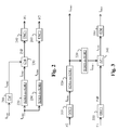
- Fig. 2 shows a diagram of the steps of a method for encoding both a HDR picture I HDR and a SDR picture I SDR1 in accordance with the present principles.
- the HDR picture I HDR is a color-graded version of a captured picture (or video) according to a first grade
- the first SDR picture I SDR1 is a color-graded version of said captured picture (or video) according to a second grade as explained above.
- the constraint on this encoding method is that the color-grade of the SDR picture I SDR1 shall be rendered at the decoder or at least a SDR picture having a visual content very close to the visual content of SDR picture I SDR1 in order to preserve the artist intent.
- a module TM obtains a second SDR picture I SDR2 by tone-mapping the HDR picture I HDR .
- tone-mapping means any approach that reduces the dynamic range of the HDR picture I HDR to a targeted dynamic range. Examples of tone-mapping approaches are given in Fig. 8a -d, 9, 10a-d but the present disclosure is not limited to a specific tone-mapping approach.
- a module SDR1-to-SDR3 obtains a third SDR picture I SDR3 from the first SDR picture I SDR1 .
- a module CM obtains a color mapping function CMF that allows the mapping of the colors of the second SDR picture I SDR2 onto the colors of the third SDR picture I SDR3 in order to minimize the differences between the second SDR picture I SDR2 and the third SDR picture I SDR3 .
- the color mapping function is obtained by minimizing a mean square error calculated by subtracting the pixel values of the third SDR picture I SDR3 from the pixels of the SDR picture I SDR2 .
- An example of color mapping function is given by the standard HEVC with color remapping information SEI message (Annex. D.2.32). The present disclosure is not limited to a specific color mapping function but extend to any kind of mapping function.
- an encoder ENC1 encodes, in a bitstream F1, an information INF representative of the color mapping function CMF.
- the information INF is an index allowing to retrieve the color mapping function CMF from a list of color mapping functions.
- the information INF represent parameters of the color mapping function CMF.
- a module SDR1-to-SDR4 obtains a fourth SDR picture I SDR4 from the first SDR picture I SDR1 .
- an encoder ENC2 encodes the fourth SDR picture I SDR4 in a bitstream F2.
- Fig. 3 shows a diagram of the steps of a method for decoding a HDR picture I HDR and a SDR picture I SDR1 in accordance with an example of the present principles.
- a decoder DEC2 obtains a decoded SDR picture, called a decoded fourth SDR picture I SDR4 , by decoding a bitstream F2.
- a module SDR4-to-SDR1 obtains a decoded first SDR picture I SDR1 from the decoded fourth SDR picture I SDR4 .
- step 220 the module SDR1-to-SDR3 obtains a decoded third SDR picture I SDR3 from the decoded first SDR picture I SDR1 .
- a decoder DEC1 obtains an information INF representative of a color mapping function CMF by decoding at least partially a bitstream F1.
- the information INF is representative of the inverse of the color mapping function CMF.
- a module AP -1 obtains a decoded second SDR picture I SDR2 by applying the inverse CMF -1 of the color mapping function CMF to the colors of the decoded third SDR picture I SDR3 .
- a module ITM obtains a decoded HDR picture I HDR by applying an inverse-tone-mapping to the decoded second SDR picture I SDR2 .
- the inverse-tone-mapping is the inverse of the tone-mapping used in step 210 in Fig. 2 .
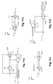
- Fig. 4 shows a diagram of the steps of an example of the method for encoding both the HDR picture I HDR and the first SDR picture I SDR1 as described in relation with Fig. 2 .
- the modules SDR1-to-SDR3 and SDR1-to-SDR4 are configured in order that the SDR pictures I SDR3 and I SDR4 equal the SDR picture I SDR1 .
- step 230 the color mapping function CMF is then obtained to allow the mapping of the colors of the second SDR picture I SDR2 onto the colors of the first SDR picture I SDR1 , and in step 260, the first SDR picture I SDR1 is directly encoded by the encoder ENC2.
- the first SDR picture I SDR1 as color-graded by the colorist is thus directly available by decoding the bitstream F2.
- the artist intent is thus preserved when the decoded first SDR picture I SDR1 is displayed.
- Fig. 5 shows a diagram of the steps of a method for encoding both a HDR picture I HDR and a SDR picture I SDR1 in accordance with a variant of Fig. 4 .
- the module SDR1-to-SDR4 is configured in order that the fourth SDR picture I SDR4 is the first SDR picture I SDRI .
- the first SDR picture I SDR1 as color-graded by the colorist, is thus directly available by decoding the bitstream F2. The artist intent is thus preserved when the decoded first picture I SDR1 is displayed.
- the module SDR1-to-SDR3 is configured to encode the first SDR picture I SDR1 by using the encoder ENC2, and to obtain the third SDR picture I SDR3 by decoding the encoded first SDR picture I SDR1 according to a decoder DEC2 (step 310).
- step 230 the color mapping function CMF is then obtained to allow the mapping of the colors of the SDR picture I SDR2 onto the colors of the decoded version of the encoded first SDR picture I SDR1 .
- Determining the color mapping function CMF from the decoded version of the encoded first SDR picture I SDR1 rather than from the first SDR picture I SDR1 leads to a decoded second SDR picture I SDR2 (obtained at the decoding side) whose the content is closer to the content of the second SDR picture I SDR2 used at the encoding side. Then, the decoded HDR picture, obtained from the decoded second SDR picture I SDR2 and the color mapping function determined from said decoded second SDR picture I SDR2 , at the encoding side, has a visual content closer to the visual content of the original HDR picture, improving the performance of the HDR encoding/decoding scheme of Fig. 4 .
- Fig. 6 shows a diagram of the steps of an example of the method for encoding both the HDR picture I HDR and the first SDR picture I SDR1 as described in relation with Fig. 2 ;
- the module SDR1-to-SDR3 is configured in order that the SDR pictures I SDR3 is the SDR picture I SDR1 .
- step 230 the color mapping function CMF is then obtained to allow the mapping of the colors of the second SDR picture I SDR2 onto the colors of a first SDR picture I SDR1 .
- the module SDR1-to-SDR4 comprises a module AP (step 610) to obtain the fourth SDR picture I SDR4 by applying the color mapping function CMF (obtained from the SDR picture I SDR1 ) onto the colors of the second SDR picture I SDR2 .
- the content of the fourth SDR picture I SDR4 is thus close to the content of the first SDR picture I SDR1 because the color mapping function CMF is determined in order to minimize the differences between these two pictures.
- Fig. 7 shows a diagram of the steps of a method for encoding both a HDR picture I HDR and a SDR picture I SDR1 in accordance with a variant of Fig. 6 .
- the module SDR1-to-SDR3 is configured to encode (step 260) the first SDR picture I SDR1 by using the encoder ENC2, and to obtain the third SDR picture I SDR3 by decoding the encoded first SDR picture I SDR1 according to the decoder DEC2 (step 310).
- Determining the color mapping function CMF from the decoded version of the encoded first SDR picture I SDR1 rather than from the first SDR picture I SDR1 leads to a decoded second SDR picture I SDR2 (obtained at the decoding side) whose the content is closer to the content of the second SDR picture I SDR2 used at the encoding side. Then, the decoded HDR picture, obtained from the decoded second SDR picture I SDR2 and the color mapping function determined from said decoded second SDR picture I SDR2 , at the encoding side, has a visual content closer to the visual content of the original HDR picture, improving the performance of the HDR encoding/decoding scheme of Fig. 6 .
- the module TM applies a tone-mapping operator onto the HDR picture I HDR in order to reduce the dynamic range of the luminance of the HDR picture I HDR to a target dynamic range.
- the invention is not limited to any specific tone-mapping operator. This single condition is that the tone-mapping operator shall be reversible.
- the tone-mapping operator defined by Reinhard may be used ( Reinhard, E., Stark, M., Shirley, P., and Ferwerda, J., Photographic tone reproduction for digital images,"ACM Transactions on Graphics 21 (July 2002 )), or defined by Boitard, R., Bouatouch, K., Cozot, R., Thoreau, D., & Gruson, A. (2012). Temporal coherency for video tone mapping. In A. M. J. van Eijk, C. C. Davis, S. M. Hammel, & A. K. Majumdar (Eds.), Proc. SPIE 8499, Applications of Digital Image Processing (p. 84990D-84990D-10 )).
- Fig. 8a -d show diagrams of the sub-steps of the step 210 in accordance with examples of the present principles.
- the module TM comprises a module BAM configured to obtain a backlight picture Ba from the HDR picture I HDR (step 2101).
- the module BAM comprises a module BI which obtains the backlight picture Ba from the luminance component L of the HDR picture I HDR .
- determining a backlight picture Ba from a luminance component L consists in finding optimal weighting coefficients (and potentially also optimal shape functions if not known beforehand) in order that the backlight picture Ba fits the luminance component L.
- weighting coefficients a i There are many well-known methods to find the weighting coefficients a i . For example, one may use a least mean square error method to minimize the mean square error between the backlight picture Ba and the luminance component L.
- shape functions may be the true physical response of a display backlight (made of LED's for instance, each shape function then corresponding to the response of one LED) or may be a pure mathematical construction in order to fit the luminance component at best.
- the module BAM further comprises a module BM which modulate the backlight picture Ba (given by equation (1)) with a mean luminance value L mean of the HDR picture I HDR obtained by the means of a module HL.
- the module HL is configured to calculate the mean luminance value L mean over the whole luminance component L.
- This last example is advantageous because it avoids that the mean luminance value L mean be influenced by a few pixels with extreme high values which usually leads to very annoying temporal mean brightness instability when the HDR picture I HDR belongs to a sequence of images.
- the invention is not limited to a specific embodiment for calculating the mean luminance value L mean .
- a module N normalizes the backlight image Ba (given by equation (1)) by its mean value E(Ba) such that one gets a backlight picture Ba gray (having a mid-grey equals to 1) for the HDR picture (or for all HDR pictures if the HDR picture belongs to a sequence or group of pictures):
- Ba gray Ba E Ba
- the module BM is configured to modulate the backlight picture Ba gray with the mean luminance value L mean of the HDR picture I HDR , by using the following relation Ba mod ⁇ cst mod . L mean ⁇ .
- Ba gray with cst mod being a modulation coefficient and ⁇ being another modulation coefficient less than 1, typically 1/3.
- cst mod ⁇ 1.7 for a backlight picture is obtained by least means squares.
- the present disclosure is not limited to any way to obtain a backlight picture Ba from the HDR picture I HDR .
- step 2102 in Fig. 8a , the second SDR picture I SDR2 is obtained by dividing, pixel by pixel, the HDR picture I HDR by the backlight picture Ba.
- an encoder ENC3 encodes the backlight picture Ba in a bitstream F3.
- Dividing the HDR picture I HDR by the backlight picture Ba reduces the dynamic range of the HDR picture.
- a method as described in relation with Fig. 8a -d may thus be considered as being a tone-mapping of the HDR picture I HDR .
- Fig. 9 shows a diagram of the steps of a method for decoding both a HDR picture and a SDR picture in accordance with an example of the present principles.
- This example allows getting both a HDR picture and a SDR picture when those pictures have been previously encoded by a method as described in relation with Figs. 8a -d.
- the module ITM in step 350, comprises a decoder DEC3 which obtains a decoded backlight picture Ba by decoding a bitstream F3 (step 3501).
- the decoded HDR picture I HDR is obtained by multiplying the second SDR picture I SDR2 by the decoded backlight picture Ba.
- Multiplying the second SDR picture I SDR2 by the decoded backlight picture Ba increases the dynamic range of the resulting HDR picture compared to the second SDR picture I SDR2 , i.e such multiplyinig may be considered as being inverse-tone-mapping.
- Fig. 10a -c show diagrams of the sub-steps of the step 210 in accordance with examples of the present principles.
- the present disclosure is not limited to any color space in which the three components Ec are represented but extends to any color space such as RGB, CIELUV, XYZ, CIELab, etc.
- a luminance component L and two chrominance components C1 and C2 are determined from the three color components Ec of the HDR picture I HDR .
- the luminance and chrominance components form a SDR color picture whose pixel values are represented in the color space (L, C1, C2).
- Said SDR color picture is viewable by a legacy SDR display, i.e. has a sufficient visual quality in order to be viewed by a legacy SDR display.
- a module BMM obtains a module value Bm from the component Y.
- the modulation value Bm is an average, median, min or max value of the pixel values of the component Y.
- These operations may be performed in the linear HDR luminance domain Y lin or in a non-linear domain like In(Y) or Y ⁇ with ⁇ 1.
- the dynamic range of the component Y is reduced in order that the luminance values of the component L are represented by using 10 bits.
- a, b and c are parameters (real values) of a SLog curve determined such that f(0) and f(1) are invariant, and the derivative of the SLog curve is continuous in 1 when prolonged by a gamma curve below 1.
- a, b and c are functions of the parameter ⁇ . Typical values are shown in Table 1. Table 1 ⁇ a B c 1/2.0 0.6275 0.2550 0.8575 1/2.4 0.4742 0.1382 0.9386 1/2.8 0.3861 0.0811 0.9699
- a value of ⁇ close to 1/2.5 is efficient in terms of HDR compression performance as well as good viewability of the obtained SDR luma.
- the non-linear function f is either a gamma correction or a SLog correction according to the pixel values of the component Y.
- the module FM applies either the gamma correction or the SLog correction according to the pixel values of the component Y.
- An information data Inf may indicate whether either the gamma correction or Slog correction applies.
- the gamma correction is applied and otherwise the SLog correction is applied.
- a modulation value Bm is determined for every HDR picture, a Group of Pictures (GOP) or for a part of a HDR picture such as, but not limited to, a slice or a Transfer Unit as defined in HEVC.
- GOP Group of Pictures
- the value Bm and/or the parameters of the non-linear function f (such as a , b , c or ⁇ ) and/or the information data Inf is (are) stored in a local or remote memory and/or added into a bitstream F3.
- a color component Ec may be obtained directly from a local or a remote memory or by applying a color transform on the HDR picture I HDR .
- Scaling by a factor means multiplying by said factor or dividing by the inverse of said factor.
- the value Y(i) of a pixel of the component Y depends non-ambiguously on the value L(i) of a pixel of the luminance component L, such that the ratio can be written as a function of L(i) only.
- This example is advantageous because scaling each color component Ec by the factor r(L) that further depends on the component Y preserves the hue of the colors of the HDR picture I HDR and thus improves the visual quality of the decoded color picture.
- colorfulness, chroma, and saturation refer to the perceived intensity of a specific color.
- Colorfulness is the degree of difference between a color and gray.
- Chroma is the colorfulness relative to the brightness of another color that appears white under similar viewing conditions.
- Saturation is the colorfulness of a color relative to its own brightness.
- a highly colorful stimulus is vivid and intense, while a less colorful stimulus appears more muted, closer to gray.
- a color is a "neutral" gray (a picture with no colorfulness in any of its colors is called grayscale). Any color can be described from its colorfulness (or chroma or saturation), lightness (or brightness), and hue.
- the definition of the hue and saturation of the color depends on the color space used to represent said color.
- the saturation s uv is defined as the ratio between the chroma C u v * over the luminance L *.
- the colors of the second SDR picture I SDR2 are thus differently perceived by a human being because the saturation and the hue of the colors changed.
- the method described in relation with Fig. 10a determines the chrominance components C1 and C2 of the second SDR picture I SDR2 in order that the hue of the colors of the second SDR picture I SDR2 best match the hue of the colors of the HDR picture I HDR .
- This last embodiment is advantageous because it prevents the factor from going to zero for very dark pixels, i.e. allows the ratio to be invertible regardless of the pixel value.
- step 160a the two chrominance components C1, C2 are obtained from said at least one intermediate color components E'c.
- This embodiment allows a reduction of the dynamic range according to a specific OETF but leads to a complex decoding process as detailed later.
- This variant is advantageous because it provides a good approximation of the OETF defined by the ITU-R recommendation BT.709 or BT.2020 and leads to a low complexity decoder.
- This variant is advantageous because it provides a good approximation of the OETF defined by the ITU-R recommendation BT.709 or BT.2020 but it leads to a somewhat more complex decoder than the decoder obtains when the OETF is approximated by a square-root.
- a module LC1 obtains the two chrominance components C1 and C2 by linearly combining the three intermediate components Dc:
- C 1 C 2 A 2 A 3 D 1 D 2 D 3 where A2 and A3 are the second and third rows of the 3x3 matrix A.
- a module COM obtains the second SDR picture I SDR2 by combining together the luminance component L and the chrominance components C1 and C2.
- Fig. 11a -d show diagrams of the steps of a method of decoding a HDR picture and a SDR picture from at least one bitstream in accordance with an example of the present principles.
- a module DECOMB obtains a luminance component L and two chrominance components C1, C2 from the second SDR picture I SDR2 .
- the non-linear function f -1 is the inverse of the non-linear function f (step 110a).
- the value Bm and/or the parameters of the non-linear function f -1 (such as a , b , c or ⁇ ) and/or the information data Inf is (are) obtained from a local or remote memory (for example a Look-Up-Table) and/or from a bitstream F3 as illustrated in Fig. 11 a.
- a local or remote memory for example a Look-Up-Table
- the non-linear function f -1 is the inverse of a gamma function.
- Y 1 L 1 / ⁇ B
- Y 1 equals Y or Y/Bm according to the embodiments of eq. (5) or (6)
- B is a constant value
- y is a parameter (real value strictly below 1).
- the non-linear function f -1 is the inverse of a S-Log function.
- the non-linear function f is the inverse of either a gamma correction or a SLog correction according to the pixel values of the component Y. This is indicated by the information data Inf.
- a module ILC obtains at least one color component Ec from the first component Y, the two chrominance component C1, C2, and from a factor r(L) that depends on the luminance component L.
- the decoded HDR picture I HDR is then obtained by combining together said at least one color component Ec.
- the factor r(L) may be obtained either from a local or remote memory (such a Look-Up-Table) or from a bitstream.
- EOTF Electro-Optical Trans Function
- OETF( E c ) D c
- ⁇ i constants depending on the matrix A
- L i linear functions also depending on the matrix A.
- equation (10) may be solved numerically by using the so-called Newton's method or any other numerical method to find the root of a regular function.
- a module ILEC obtains three intermediate color component E'c from the first component Y, the two chrominance component C1, C2 and the factor r(L) as above explained.
- step 1121 a before step 1122a is the inverse of the order step 161 b followed by step 162b of the encoding method ( Fig. 10b ) .
- the OEFT is a square root function and the EOTF is then a square function.
- the OEFT is a cubic root function and the EOTF is then a cubic function.
- OETF x * y OETF x * OETF y
- step 1121c When the OETF fulfills the commutation conditions, according to a second example of the step 112a, illustrated in Fig. 11c , in step 1121c, two intermediate components C'1 and C'2 are obtained by scaling the two chrominance components C1 and C2 by the factor OEFT(r(L(i))) where OETF is the function used in step 161 b in Fig.
- a module ILEC obtains the three color components Ec from the first component Y and the two intermediate chrominance components C'1, C'2 as above explained.
- the OEFT is a square root function and the EOTF is then a square function.
- the two intermediate components C'1 and C'2 are obtained by scaling the two chrominance components C1 and C2 by the factor r ( L ( i ))
- Equation (17) is a second order equation that may be solved analytically.
- This analytic solution leads to a specific embodiment of the step 1122c as illustrated in Fig. 11d .
- This embodiment is advantageous because it allows an analytic expression of the EOTF (inverse of the OETF), and thus of the decoded components of the HDR picture. Moreover, the EOTF is then the square function that is a low complexity process at the decoding side.
- the matrix A determines the transform of the HDR picture I HDR to be encoded from the color space (E1, E2, E3), in which the pixel values of the HDR picture to be encoded are represented, to the color space (Y, C1, C2).
- Such a matrix depends on the gamut of the HDR picture I HDR to be encoded.
- the OETF is a cubic root function and the EOTF is then a cubic function.
- the EOTF is then a cubic function thus leading to an equation (17) on F 1 being a more complex third order equation which can be solved analytically by the so-called Cardano's method.
- the decoder DEC1 (respectively DEC2, DEC3) is configured to decode data which have been encoded by the encoder ENC1 (respectively ENC2, ENC3).
- the encoder ENC1 and/or ENC2 and/or ENC3 (and decoder DEC1 and/or DEC2 and/or DEC3) may be block-based processing.
- the encoders ENC1 and/or ENC2 and/or ENC3 (and decoder DEC1 and/or DEC2 and/or DEC3) is not limited to a specific encoder (decoder).
- the encoder ENC1 is configured to encode the information INF in a SEI message such as the color remapping information SEI message as defined in the HEVC standard (Annex D.2.32).
- the encoder ENC3 is configured to encode the backlight picture Ba as an auxiliary picture or by using frame packing (Annex D.2.16) as described in the HEVC standard, or to encode the weighting coefficients and possibly the shape functions in a SEI message (HEVC standard, Annex D1).
- the decoder DEC3 is configured to ...the decoded backlight picture Ba obtained from an auxiliary picture or a packed frame encoded in the bitstream F1 as described in the HEVC standard, or is obtained from weighting coefficients and possibly shape functions obtained from a SEI message in the bitstream F1.
- the encoder ENC1 and/or ENC2 (and decoder DEC1 and/or DEC2) is not limited to a specific encoder which may be, for example, an image/video coder with loss like JPEG, JPEG2000, MPEG2, HEVC recommendation or H264/AVC recommendation (" Advanced video coding for generic audiovisual Services ", SERIES H: AUDIOVISUAL AND MULTIMEDIA SYSTEMS, Recommendation ITU-T H.264, Telecommunication Standardization Sector of ITU, February 2014)).
- bitstreams F1, F2, F3 may be multiplexed together to form a single bitstream.
- the modules are functional units, which may or not be in relation with distinguishable physical units. For example, these modules or some of them may be brought together in a unique component or circuit, or contribute to functionalities of a software. A contrario, some modules may potentially be composed of separate physical entities.
- the apparatus which are compatible with the disclosure are implemented using either pure hardware, for example using dedicated hardware such ASIC or FPGA or VLSI, respectively «Application Specific Integrated Circuit » « Field-Programmable Gate Array » « Very Large Scale Integration » or from several integrated electronic components embedded in a device or from a blend of hardware and software components.
- Fig. 12 represents an exemplary architecture of a device 1200 which may be configured to implement a method described in relation with Fig. 1- 11d.
- Device 1200 comprises following elements that are linked together by a data and address bus 1201:
- the battery 1206 is external to the device.
- the word « register» used in the specification can correspond to area of small capacity (some bits) or to very large area (e.g. a whole program or large amount of received or decoded data).
- the ROM 1203 comprises at least a program and parameters. The ROM 1203 may store algorithms and instructions to perform techniques in accordance with present principles. When switched on, the CPU 1202 uploads the program in the RAM and executes the corresponding instructions.
- RAM 1204 comprises, in a register, the program executed by the CPU 1202 and uploaded after switch on of the device 1200, input data in a register, intermediate data in different states of the method in a register, and other variables used for the execution of the method in a register.
- the implementations described herein may be implemented in, for example, a method or a process, an apparatus, a software program, a data stream, or a signal. Even if only discussed in the context of a single form of implementation (for example, discussed only as a method or a device), the implementation of features discussed may also be implemented in other forms (for example a program).
- An apparatus may be implemented in, for example, appropriate hardware, software, and firmware.
- the methods may be implemented in, for example, an apparatus such as, for example, a processor, which refers to processing devices in general, including, for example, a computer, a microprocessor, an integrated circuit, or a programmable logic device. Processors also include communication devices, such as, for example, computers, cell phones, portable/personal digital assistants ("PDAs”), and other devices that facilitate communication of information between end-users.
- PDAs portable/personal digital assistants
- the HDR or SDR picture is obtained from a source.
- the source belongs to a set comprising:
- the decoded SDR or HDR picture is sent to a destination; specifically, the destination belongs to a set comprising:
- bitstream F1, F2 and/or F3 are sent to a destination.
- bitstreams F1, F2 and F3 or both bitstreams are stored in a local or remote memory, e.g. a video memory (1204) or a RAM (1204), a hard disk (1203).
- one or both bitstreams are sent to a storage interface (1205), e.g. an interface with a mass storage, a flash memory, ROM, an optical disc or a magnetic support and/or transmitted over a communication interface (1205), e.g. an interface to a point to point link, a communication bus, a point to multipoint link or a broadcast network.
- the bitstream F1, F2 and/or F3 is obtained from a source.
- the bitstream is read from a local memory, e.g. a video memory (1204), a RAM (1204), a ROM (1203), a flash memory (1203) or a hard disk (1203).
- the bitstream is received from a storage interface (1205), e.g. an interface with a mass storage, a RAM, a ROM, a flash memory, an optical disc or a magnetic support and/or received from a communication interface (1205), e.g. an interface to a point to point link, a bus, a point to multipoint link or a broadcast network.
- device 1200 being configured to implement an encoding method described in relation with one of the Figs. 2 , 4-8d , 10a-c , belongs to a set comprising:
- device 1200 being configured to implement a decoding method described in relation with one of the Figs. 3 , 9 11a-d , belongs to a set comprising:
- the device A comprises a processor in relation with memory RAM and ROM which are configured to implement a method for encoding a picture as described in relation with one of the Figs. 2 , 4-8d , 10a-c
- the device B comprises a processor in relation with memory RAM and ROM which are configured to implement which are configured to implement a method for decoding as described in relation with one of the Figs. 3 , 9 11a-d .
- the network is a broadcast network, adapted to broadcast still pictures or video pictures from device A to decoding devices including the device B.
- Implementations of the various processes and features described herein may be embodied in a variety of different equipment or applications.
- Examples of such equipment include an encoder, a decoder, a post-processor processing output from a decoder, a pre-processor providing input to an encoder, a video coder, a video decoder, a video codec, a web server, a set-top box, a laptop, a personal computer, a cell phone, a PDA, and any other device for processing a picture or a video or other communication devices.
- the equipment may be mobile and even installed in a mobile vehicle.
- a computer readable storage medium can take the form of a computer readable program product embodied in one or more computer readable medium(s) and having computer readable program code embodied thereon that is executable by a computer.
- a computer readable storage medium as used herein is considered a non-transitory storage medium given the inherent capability to store the information therein as well as the inherent capability to provide retrieval of the information therefrom.
- a computer readable storage medium can be, for example, but is not limited to, an electronic, magnetic, optical, electromagnetic, infrared, or semiconductor system, apparatus, or device, or any suitable combination of the foregoing. It is to be appreciated that the following, while providing more specific examples of computer readable storage mediums to which the present principles can be applied, is merely an illustrative and not exhaustive listing as is readily appreciated by one of ordinary skill in the art: a portable computer diskette; a hard disk; a read-only memory (ROM); an erasable programmable read-only memory (EPROM or Flash memory); a portable compact disc read-only memory (CD-ROM); an optical storage device; a magnetic storage device; or any suitable combination of the foregoing.
- the instructions may form an application program tangibly embodied on a processor-readable medium.
- Instructions may be, for example, in hardware, firmware, software, or a combination. Instructions may be found in, for example, an operating system, a separate application, or a combination of the two.
- a processor may be characterized, therefore, as, for example, both a device configured to carry out a process and a device that includes a processor-readable medium (such as a storage device) having instructions for carrying out a process. Further, a processor-readable medium may store, in addition to or in lieu of instructions, data values produced by an implementation.
- implementations may produce a variety of signals formatted to carry information that may be, for example, stored or transmitted.
- the information may include, for example, instructions for performing a method, or data produced by one of the described implementations.
- a signal may be formatted to carry as data the rules for writing or reading the syntax of a described embodiment, or to carry as data the actual syntax-values written by a described embodiment.
- Such a signal may be formatted, for example, as an electromagnetic wave (for example, using a radio frequency portion of spectrum) or as a baseband signal.
- the formatting may include, for example, encoding a data stream and modulating a carrier with the encoded data stream.
- the information that the signal carries may be, for example, analog or digital information.
- the signal may be transmitted over a variety of different wired or wireless links, as is known.
- the signal may be stored on a processor-readable medium.
Landscapes
- Engineering & Computer Science (AREA)
- Multimedia (AREA)
- Signal Processing (AREA)
- Compression Or Coding Systems Of Tv Signals (AREA)
Priority Applications (9)
| Application Number | Priority Date | Filing Date | Title |
|---|---|---|---|
| EP15306048.8A EP3113496A1 (fr) | 2015-06-30 | 2015-06-30 | Procédé et dispositif de codage d'une image hdr et d'une image sdr obtenus à partir de l'image hdr au moyen de fonctions de mappage de couleurs |
| TW105119816A TWI763629B (zh) | 2015-06-30 | 2016-06-24 | 將高動態範圍圖像與使用色映射函數從該高動態範圍圖像得到之標準動態範圍圖像兩者編碼之方法及裝置 |
| US15/741,257 US11006151B2 (en) | 2015-06-30 | 2016-06-27 | Method and device for encoding both a HDR picture and a SDR picture obtained from said HDR picture using color mapping functions |
| CN201680039146.4A CN107852501A (zh) | 2015-06-30 | 2016-06-27 | 用于对hdr图像和使用色彩映射函数从所述hdr图像获得的sdr图像两者进行编码的方法和设备 |
| JP2017568278A JP2018524924A (ja) | 2015-06-30 | 2016-06-27 | Hdrピクチャ及び前記hdrピクチャから得られるsdrピクチャの両方をカラーマッピング関数を使用して符号化するための方法及びデバイス |
| KR1020177037932A KR102367205B1 (ko) | 2015-06-30 | 2016-06-27 | 컬러 맵핑 함수들을 이용하여 hdr 픽처 및 상기 hdr 픽처로부터 획득된 sdr 픽처의 양자를 인코딩하기 위한 방법 및 디바이스 |
| CN202111557943.0A CN114189691A (zh) | 2015-06-30 | 2016-06-27 | 用于对hdr图像和使用色彩映射函数的sdr图像两者进行编码的方法和设备 |
| EP16775474.6A EP3318063A1 (fr) | 2015-06-30 | 2016-06-27 | Procédé et dispositif pour coder à la fois une image hdr et une image sdr obtenue à partir de ladite image hdr à l'aide de fonctions de mappage de couleurs |
| PCT/EP2016/064837 WO2017001330A1 (fr) | 2015-06-30 | 2016-06-27 | Procédé et dispositif pour coder à la fois une image hdr et une image sdr obtenue à partir de ladite image hdr à l'aide de fonctions de mappage de couleurs |
Applications Claiming Priority (1)
| Application Number | Priority Date | Filing Date | Title |
|---|---|---|---|
| EP15306048.8A EP3113496A1 (fr) | 2015-06-30 | 2015-06-30 | Procédé et dispositif de codage d'une image hdr et d'une image sdr obtenus à partir de l'image hdr au moyen de fonctions de mappage de couleurs |
Publications (1)
| Publication Number | Publication Date |
|---|---|
| EP3113496A1 true EP3113496A1 (fr) | 2017-01-04 |
Family
ID=53724153
Family Applications (2)
| Application Number | Title | Priority Date | Filing Date |
|---|---|---|---|
| EP15306048.8A Withdrawn EP3113496A1 (fr) | 2015-06-30 | 2015-06-30 | Procédé et dispositif de codage d'une image hdr et d'une image sdr obtenus à partir de l'image hdr au moyen de fonctions de mappage de couleurs |
| EP16775474.6A Pending EP3318063A1 (fr) | 2015-06-30 | 2016-06-27 | Procédé et dispositif pour coder à la fois une image hdr et une image sdr obtenue à partir de ladite image hdr à l'aide de fonctions de mappage de couleurs |
Family Applications After (1)
| Application Number | Title | Priority Date | Filing Date |
|---|---|---|---|
| EP16775474.6A Pending EP3318063A1 (fr) | 2015-06-30 | 2016-06-27 | Procédé et dispositif pour coder à la fois une image hdr et une image sdr obtenue à partir de ladite image hdr à l'aide de fonctions de mappage de couleurs |
Country Status (7)
| Country | Link |
|---|---|
| US (1) | US11006151B2 (fr) |
| EP (2) | EP3113496A1 (fr) |
| JP (1) | JP2018524924A (fr) |
| KR (1) | KR102367205B1 (fr) |
| CN (2) | CN107852501A (fr) |
| TW (1) | TWI763629B (fr) |
| WO (1) | WO2017001330A1 (fr) |
Cited By (1)
| Publication number | Priority date | Publication date | Assignee | Title |
|---|---|---|---|---|
| CN108513134A (zh) * | 2017-02-24 | 2018-09-07 | 汤姆逊许可公司 | 根据解码后的图像数据重建图像数据的方法和设备 |
Families Citing this family (10)
| Publication number | Priority date | Publication date | Assignee | Title |
|---|---|---|---|---|
| US20180139360A1 (en) * | 2015-05-18 | 2018-05-17 | Thomson Licensing | Method and device for processing color image data representing colors of a color gamut |
| WO2017040237A1 (fr) * | 2015-08-28 | 2017-03-09 | Arris Enterprises Llc | Transformées de volume de couleur dans le codage de séquences à plage dynamique élevée et à large de couleurs |
| US10574959B2 (en) * | 2017-07-05 | 2020-02-25 | Qualcomm Incorporated | Color remapping for non-4:4:4 format video content |
| CN111466117A (zh) * | 2017-12-12 | 2020-07-28 | 交互数字Vc控股公司 | 处理图像 |
| US20190356891A1 (en) * | 2018-05-16 | 2019-11-21 | Synaptics Incorporated | High dynamic range (hdr) data conversion and color space mapping |
| EP3672254A1 (fr) * | 2018-12-21 | 2020-06-24 | InterDigital VC Holdings, Inc. | Décodage d'une image |
| CN113257174B (zh) * | 2021-04-26 | 2022-07-12 | 长春希达电子技术有限公司 | 一种led显示屏色度校正目标色域的确定方法 |
| CN114222187B (zh) * | 2021-08-12 | 2023-08-29 | 荣耀终端有限公司 | 视频编辑方法和电子设备 |
| CN115797152A (zh) * | 2021-09-10 | 2023-03-14 | 北京字跳网络技术有限公司 | 一种颜色映射色卡生成方法及装置 |
| WO2023140514A1 (fr) * | 2022-01-19 | 2023-07-27 | 삼성전자주식회사 | Dispositif électronique et procédé de commande associé |
Citations (2)
| Publication number | Priority date | Publication date | Assignee | Title |
|---|---|---|---|---|
| US20100166301A1 (en) * | 2008-12-31 | 2010-07-01 | Jeon Seung-Hun | Real-time image generator |
| WO2014128586A1 (fr) * | 2013-02-21 | 2014-08-28 | Koninklijke Philips N.V. | Procédés et dispositifs de codage et de décodage amélioré d'images à grande gamme dynamique |
Family Cites Families (38)
| Publication number | Priority date | Publication date | Assignee | Title |
|---|---|---|---|---|
| JP3134784B2 (ja) | 1996-08-05 | 2001-02-13 | 松下電器産業株式会社 | 画像合成回路 |
| JP4040171B2 (ja) | 1998-04-24 | 2008-01-30 | キヤノン株式会社 | 信号処理装置 |
| US8698840B2 (en) | 1999-03-05 | 2014-04-15 | Csr Technology Inc. | Method and apparatus for processing video and graphics data to create a composite output image having independent and separate layers of video and graphics display planes |
| JP4003399B2 (ja) | 2000-10-23 | 2007-11-07 | ソニー株式会社 | 画像処理装置および方法、並びに記録媒体 |
| US7106352B2 (en) | 2003-03-03 | 2006-09-12 | Sun Microsystems, Inc. | Automatic gain control, brightness compression, and super-intensity samples |
| CN100525471C (zh) | 2003-09-12 | 2009-08-05 | 皇家飞利浦电子股份有限公司 | 用于控制亮度的亮度控制方法和亮度控制设备以及计算机系统 |
| EP2988499B1 (fr) | 2006-01-23 | 2017-03-22 | Max-Planck-Gesellschaft zur Förderung der Wissenschaften e.V. | Codecs à plage dynamique étendue |
| US8014445B2 (en) | 2006-02-24 | 2011-09-06 | Sharp Laboratories Of America, Inc. | Methods and systems for high dynamic range video coding |
| US7558436B2 (en) | 2006-07-20 | 2009-07-07 | Max-Viz, Inc. | Image dynamic range control for visual display |
| RU2460153C2 (ru) | 2006-10-12 | 2012-08-27 | Конинклейке Филипс Электроникс Н.В. | Способ отображения цветов |
| US7826673B2 (en) | 2007-01-23 | 2010-11-02 | Sharp Laboratories Of America, Inc. | Methods and systems for inter-layer image prediction with color-conversion |
| US8737474B2 (en) * | 2007-06-27 | 2014-05-27 | Thomson Licensing | Method and apparatus for encoding and/or decoding video data using enhancement layer residual prediction for bit depth scalability |
| EP2051527A1 (fr) * | 2007-10-15 | 2009-04-22 | Thomson Licensing | Amélioration de prédiction résiduelle de couche pour extensibilité de profondeur de bit utilisant les LUT hiérarchiques |
| US8411206B2 (en) | 2007-12-27 | 2013-04-02 | Texas Instruments Incorporated | Apparatus and method for decoding extended color space data |
| BRPI1009443B1 (pt) * | 2009-03-13 | 2021-08-24 | Dolby Laboratories Licensing Corporation | Método de geração de parâmetros de mapeamento de tons inverso, método de compactação de dados de vídeo e método para geração de um fluxo de bits de saída a partir de um fluxo de bits de entrada |
| US20130107956A1 (en) | 2010-07-06 | 2013-05-02 | Koninklijke Philips Electronics N.V. | Generation of high dynamic range images from low dynamic range images |
| WO2012122426A1 (fr) | 2011-03-10 | 2012-09-13 | Dolby Laboratories Licensing Corporation | Traitement de référence pour un codage vidéo échelonnable selon la profondeur de bits et le format de couleur |
| TWI538473B (zh) * | 2011-03-15 | 2016-06-11 | 杜比實驗室特許公司 | 影像資料轉換的方法與設備 |
| WO2012142506A1 (fr) | 2011-04-14 | 2012-10-18 | Dolby Laboratories Licensing Corporation | Prévision d'image basée sur un modèle d'étalonnage de couleur primaire |
| TWI624182B (zh) | 2011-04-15 | 2018-05-11 | 杜比實驗室特許公司 | 高動態範圍影像的編碼、解碼及表示 |
| US9292940B2 (en) * | 2011-04-28 | 2016-03-22 | Koninklijke Philips N.V. | Method and apparatus for generating an image coding signal |
| EP2702766B1 (fr) | 2011-04-28 | 2017-06-14 | Koninklijke Philips N.V. | Appareils et procédés pour le codage et le décodage d'images à gamme dynamique élevée |
| CN103765436B (zh) | 2011-08-26 | 2017-05-31 | 皇家飞利浦有限公司 | 失真减小的信号检测 |
| RU2643485C2 (ru) | 2011-09-27 | 2018-02-01 | Конинклейке Филипс Н.В. | Устройство и способ для преобразования динамического диапазона изображений |
| US8872981B1 (en) | 2011-12-15 | 2014-10-28 | Dolby Laboratories Licensing Corporation | Backwards-compatible delivery of digital cinema content with extended dynamic range |
| TWI556629B (zh) | 2012-01-03 | 2016-11-01 | 杜比實驗室特許公司 | 規定視覺動態範圍編碼操作及參數 |
| US9438904B2 (en) | 2012-01-19 | 2016-09-06 | Futurewei Technologies, Inc. | Reduced look-up table for LM mode calculation |
| RU2652465C2 (ru) | 2012-07-13 | 2018-04-26 | Конинклейке Филипс Н.В. | Усовершенствованные способы и устройства для кодирования и декодирования hdr изображений |
| CN104364820B (zh) | 2012-10-08 | 2018-04-10 | 皇家飞利浦有限公司 | 具有颜色约束的亮度改变图像处理 |
| KR102149115B1 (ko) | 2012-11-16 | 2020-08-27 | 인터디지털 브이씨 홀딩스 인코포레이티드 | 높은 동적 범위 이미지들의 프로세싱 |
| JP6038360B2 (ja) | 2013-06-17 | 2016-12-07 | ドルビー ラボラトリーズ ライセンシング コーポレイション | エンハンストダイナミックレンジ信号の階層符号化のための適応的再構成 |
| EP2819414A3 (fr) | 2013-06-28 | 2015-02-25 | Samsung Electronics Co., Ltd | Procédé et dispositif de traitement d'images |
| JP6351313B2 (ja) | 2013-07-11 | 2018-07-04 | キヤノン株式会社 | 画像符号化装置、画像復号装置、画像処理装置、並びにそれらの制御方法 |
| CN106713697B (zh) * | 2013-10-22 | 2019-02-12 | 杜比实验室特许公司 | 用于扩展动态范围图像的引导颜色分级 |
| WO2015097118A1 (fr) | 2013-12-27 | 2015-07-02 | Thomson Licensing | Procédé et dispositif de codage d'une image à grande gamme dynamique en un flux binaire et/ou de décodage d'un flux binaire représentant une image à grande gamme dynamique |
| EP2890129A1 (fr) | 2013-12-27 | 2015-07-01 | Thomson Licensing | Procédé et dispositif de codage d'une image à plage dynamique élevée et/ou de décodage d'un train binaire |
| EP2958327A1 (fr) | 2014-06-20 | 2015-12-23 | Thomson Licensing | Procédé et dispositif de codage d'une séquence d'images |
| CN107211130B (zh) | 2015-01-30 | 2020-07-24 | 交互数字Vc控股公司 | 对彩色画面进行编码和解码的方法和装置 |
-
2015
- 2015-06-30 EP EP15306048.8A patent/EP3113496A1/fr not_active Withdrawn
-
2016
- 2016-06-24 TW TW105119816A patent/TWI763629B/zh active
- 2016-06-27 CN CN201680039146.4A patent/CN107852501A/zh active Pending
- 2016-06-27 JP JP2017568278A patent/JP2018524924A/ja active Pending
- 2016-06-27 WO PCT/EP2016/064837 patent/WO2017001330A1/fr active Application Filing
- 2016-06-27 CN CN202111557943.0A patent/CN114189691A/zh active Pending
- 2016-06-27 EP EP16775474.6A patent/EP3318063A1/fr active Pending
- 2016-06-27 US US15/741,257 patent/US11006151B2/en active Active
- 2016-06-27 KR KR1020177037932A patent/KR102367205B1/ko active IP Right Grant
Patent Citations (2)
| Publication number | Priority date | Publication date | Assignee | Title |
|---|---|---|---|---|
| US20100166301A1 (en) * | 2008-12-31 | 2010-07-01 | Jeon Seung-Hun | Real-time image generator |
| WO2014128586A1 (fr) * | 2013-02-21 | 2014-08-28 | Koninklijke Philips N.V. | Procédés et dispositifs de codage et de décodage amélioré d'images à grande gamme dynamique |
Non-Patent Citations (6)
| Title |
|---|
| "High Efficiency Video Coding", SERIES H: AUDIOVISUAL AND MULTIMEDIA SYSTEMS, RECOMMENDATION ITU-T H.265, TELECOMMUNICATION STANDARDIZATION SECTOR OF ITU, October 2014 (2014-10-01) |
| BOITARD, R.; BOUATOUCH, K.; COZOT, R.; THOREAU, D.; GRUSON, A.: "Proc. SPIE 8499, Applications of Digital Image Processing", 2012, article "Temporal coherency for video tone mapping", pages: 84990D - 84990D,1 |
| LASSERRE S ET AL: "Single layer low-bit depth EDR video coding with SDR/HDR backward compatibilities", 111. MPEG MEETING; 6-2-2015 - 20-2-2015; GENEVA; (MOTION PICTURE EXPERT GROUP OR ISO/IEC JTC1/SC29/WG11),, no. m36083, 17 February 2015 (2015-02-17), XP030064451 * |
| REC. ITU-R BT.2020-1, June 2014 (2014-06-01) |
| REC. ITU-R BT.709-5, April 2002 (2002-04-01) |
| REINHARD, E.; STARK, M.; SHIRLEY, P.; FERWERDA, J.: "\Photographic tone reproduction for digital images", ACM TRANSACTIONS ON GRAPHICS 21, July 2002 (2002-07-01) |
Cited By (2)
| Publication number | Priority date | Publication date | Assignee | Title |
|---|---|---|---|---|
| CN108513134A (zh) * | 2017-02-24 | 2018-09-07 | 汤姆逊许可公司 | 根据解码后的图像数据重建图像数据的方法和设备 |
| CN108513134B (zh) * | 2017-02-24 | 2023-05-26 | 交互数字Vc控股公司 | 根据解码后的图像数据重建图像数据的方法和设备 |
Also Published As
| Publication number | Publication date |
|---|---|
| KR20180021747A (ko) | 2018-03-05 |
| EP3318063A1 (fr) | 2018-05-09 |
| WO2017001330A1 (fr) | 2017-01-05 |
| US20180192077A1 (en) | 2018-07-05 |
| TW201701658A (zh) | 2017-01-01 |
| TWI763629B (zh) | 2022-05-11 |
| CN114189691A (zh) | 2022-03-15 |
| US11006151B2 (en) | 2021-05-11 |
| JP2018524924A (ja) | 2018-08-30 |
| CN107852501A (zh) | 2018-03-27 |
| KR102367205B1 (ko) | 2022-02-23 |
Similar Documents
| Publication | Publication Date | Title |
|---|---|---|
| US11178412B2 (en) | Method and apparatus of encoding and decoding a color picture | |
| US11006151B2 (en) | Method and device for encoding both a HDR picture and a SDR picture obtained from said HDR picture using color mapping functions | |
| RU2710291C2 (ru) | Способы и устройства для кодирования и декодирования цветного изображения hdr | |
| US11647213B2 (en) | Method and device for decoding a color picture | |
| EP3430807B1 (fr) | Procédé et dispositif permettant de coder une image à plage dynamique élevée, procédé et dispositif de décodage correspondants | |
| EP3251336B1 (fr) | Procédé et dispositif de mise en correspondance de couleurs entre images en couleur de plage dynamique différente | |
| EP3341918B1 (fr) | Procédé de codage et de décodage et dispositifs correspondants | |
| EP3051489A1 (fr) | Procédé et appareil de codage et de décodage d'une image couleur | |
| US20180014024A1 (en) | Method and apparatus of encoding and decoding a color picture | |
| EP3051792A1 (fr) | Procédé et dispositif de mise en correspondance de couleurs entre images en couleur de plage dynamique différente | |
| EP3099073A1 (fr) | Procédé et dispositif de codage/décodage d'une image hdr et sdr dans/à partir d'un train binaire évolutif |
Legal Events
| Date | Code | Title | Description |
|---|---|---|---|
| PUAI | Public reference made under article 153(3) epc to a published international application that has entered the european phase |
Free format text: ORIGINAL CODE: 0009012 |
|
| AK | Designated contracting states |
Kind code of ref document: A1 Designated state(s): AL AT BE BG CH CY CZ DE DK EE ES FI FR GB GR HR HU IE IS IT LI LT LU LV MC MK MT NL NO PL PT RO RS SE SI SK SM TR |
|
| AX | Request for extension of the european patent |
Extension state: BA ME |
|
| STAA | Information on the status of an ep patent application or granted ep patent |
Free format text: STATUS: THE APPLICATION IS DEEMED TO BE WITHDRAWN |
|
| 18D | Application deemed to be withdrawn |
Effective date: 20170705 |