EP3099073A1 - Procédé et dispositif de codage/décodage d'une image hdr et sdr dans/à partir d'un train binaire évolutif - Google Patents
Procédé et dispositif de codage/décodage d'une image hdr et sdr dans/à partir d'un train binaire évolutif Download PDFInfo
- Publication number
- EP3099073A1 EP3099073A1 EP15305795.5A EP15305795A EP3099073A1 EP 3099073 A1 EP3099073 A1 EP 3099073A1 EP 15305795 A EP15305795 A EP 15305795A EP 3099073 A1 EP3099073 A1 EP 3099073A1
- Authority
- EP
- European Patent Office
- Prior art keywords
- picture
- component
- hdr
- luminance
- obtaining
- Prior art date
- Legal status (The legal status is an assumption and is not a legal conclusion. Google has not performed a legal analysis and makes no representation as to the accuracy of the status listed.)
- Withdrawn
Links
Images


Classifications
-
- H—ELECTRICITY
- H04—ELECTRIC COMMUNICATION TECHNIQUE
- H04N—PICTORIAL COMMUNICATION, e.g. TELEVISION
- H04N19/00—Methods or arrangements for coding, decoding, compressing or decompressing digital video signals
- H04N19/30—Methods or arrangements for coding, decoding, compressing or decompressing digital video signals using hierarchical techniques, e.g. scalability
-
- H—ELECTRICITY
- H04—ELECTRIC COMMUNICATION TECHNIQUE
- H04N—PICTORIAL COMMUNICATION, e.g. TELEVISION
- H04N19/00—Methods or arrangements for coding, decoding, compressing or decompressing digital video signals
- H04N19/90—Methods or arrangements for coding, decoding, compressing or decompressing digital video signals using coding techniques not provided for in groups H04N19/10-H04N19/85, e.g. fractals
- H04N19/98—Adaptive-dynamic-range coding [ADRC]
Definitions
- the present principles generally relates to picture/video encoding and decoding. Particularly, but not exclusively, the technical field of the present principles is related to encoding/decoding of both a picture whose pixels values belong to a high-dynamic range and a picture whose pixels values belong to a low-dynamic range.
- a picture contains one or several arrays of samples (pixel values) in a specific picture/video format which specifies all information relative to the pixel values of a picture (or a video) and all information which may be used by a display and/or any other device to visualize and/or decode a picture (or video) for example.
- a picture comprises at least one component, in the shape of a first array of samples, usually a luma (or luminance) component, and, possibly, at least one other component, in the shape of at least one other array of samples, usually a color component.
- the same information may also be represented by a set of arrays of color samples, such as the traditional tri-chromatic RGB representation.
- a pixel value is represented by a vector of C values, where C is the number of components.
- Each value of a vector is represented with a number of bits which defines a maximal dynamic range of the pixel values.
- Standard-Dynamic-Range pictures are color pictures whose luminance values are represented with a limited dynamic usually measured in power of two or f-stops.
- SDR pictures have a dynamic range, also called a dynamic in the following, around 10 f-stops, i.e. a ratio 1000 between the brightest pixels and the darkest pixels in the linear domain, and are coded with a limited number of bits (most often 8 or 10 in HDTV (High Definition Television systems) and UHDTV (Ultra-High Definition Television systems) in a non-linear domain, for instance by using the ITU-R BT.709 OETF (Optico-Electrical-Transfer-Function) ( Rec.
- This limited non-linear representation does not allow correct rendering of small signal variations, in particular in dark and bright luminance ranges.
- High-Dynamic-Range pictures the signal dynamic is much higher (up to 20 f-stops, a ratio one million between the brightest pixels and the darkest pixels) and a new non-linear representation is needed in order to maintain a high accuracy of the signal over its entire range.
- raw data are usually represented in floating-point format (either 32-bit or 16-bit for each component, namely float or half-float), the most popular format being openEXR half-float format (16-bit per RGB component, i.e. 48 bits per pixel) or in integers with a long representation, typically at least 16 bits.
- floating-point format either 32-bit or 16-bit for each component, namely float or half-float
- openEXR half-float format (16-bit per RGB component, i.e. 48 bits per pixel
- integers with a long representation typically at least 16 bits.
- a color gamut is a certain complete set of colors. The most common usage refers to a set of colors which can be accurately represented in a given circumstance, such as within a given color space or by a certain output device.
- a color gamut is sometimes defined by RGB primaries provided in the CIE1931 color space chromaticity diagram and a white point as illustrated in Fig. 3 .
- a gamut is defined in this diagram by the triangle whose vertices are the set of (x,y) coordinates of the three primaries RGB.
- the white point W is another given (x,y) point belonging to the triangle, usually close to the triangle center.
- a color volume is defined by a color space and a dynamic range of the values represented in said color space.
- a color gamut is defined by a RGB ITU-R Recommendation BT.2020 color space for UHDTV.
- An older standard, ITU-R Recommendation BT.709 defines a smaller color gamut for HDTV.
- the dynamic range is defined officially up to 100 nits (candela per square meter) for the color volume in which data are coded, although some display technologies may show brighter pixels.
- a change of gamut i.e. a transform that maps the three primaries and the white point from a gamut to another, can be performed by using a 3x3 matrix in the linear RGB color space.
- a change of space from XYZ to RGB is performed by a 3x3 matrix.
- a change of gamut can be performed by a 3x3 matrix.
- a gamut change from BT.2020 linear RGB to BT.709 XYZ can be performed by a 3x3 matrix.
- High Dynamic Range pictures are color pictures whose luminance values are represented with a HDR dynamic that is higher than the dynamic of a SDR picture.
- the HDR dynamic is not yet defined by a standard but one may expect a dynamic range up to a few thousands nits.
- a HDR color volume is defined by a RGB BT.2020 color space and the values represented in said RGB color space belong to a dynamic range from 0 to 4000 nits.
- Another example of HDR color volume is defined by a RGB BT.2020 color space and the values represented in said RGB color space belong to a dynamic range from 0 to 1000 nits.
- Color-grading a picture is a process of altering/enhancing the colors of the picture (or the video).
- color-grading a picture involves a change of the color volume (color space and/or dynamic range) or a change of the color gamut relative to this picture.
- two different color-graded versions of a same picture are versions of this picture whose values are represented in different color volumes (or color gamut) or versions of the picture whose at least one of their colors has been altered/enhanced according to different color grades. This may involve user interactions.
- RGB color values composed of 3 components (Red, Green and Blue).
- the RGB color values depend on the tri-chromatic characteristics (color primaries) of the sensor.
- a HDR color-graded version of the captured picture (or video) is then obtained in order to get theatrical renders (using a specific theatrical grade).
- the values of the first color-graded version of the captured picture (or video) are represented according to a standardized YUV format such as BT.2020 which defines parameter values for UHDTV.
- the YUV format is typically performed by applying a non-linear function, so called Optical Electronic Transfer Function (OETF) on the linear RGB components to obtain non-linear components R'G'B', and then applying a color transform (usually a 3x3 matrix) on the obtained non-linear R'G'B' components to obtain the three components YUV.
- OETF Optical Electronic Transfer Function
- the first component Y is a luminance component and the two components U,V are chrominance components.
- a Colorist usually in conjunction with a Director of Photography, performs a control on the color values of the first color-graded version of the captured picture (or video) by fine-tuning/tweaking some color values in order to instill an artistic intent.
- a color-graded SDR version of the captured picture (or video) is also usually obtained in order to get home renders (using a specific home grade).
- the values of the color-graded SDR picture (or video) are represented according to a standardized YUV format such as BT.709 which defines parameter values for HDTV.
- the Colorist performs also a control on the color values of the color-graded SDR picture by fine-tuning/tweaking some color values in order to instill an artistic intent.
- the problem to be solved is the distribution of both the HDR and SDR color-graded versions of the captured picture (or video), i.e. the distribution of a compressed HDR picture (or video) representative of a color-graded version of a captured picture (or video) while, at the same time, distributing an associated SDR picture (or video) representative of a color-graded SDR version of said captured picture (or video).
- a trivial solution is simulcasting both these HDR and SDR color-graded pictures (or videos) on distribution infrastructure.
- the drawback of this solution is to virtually double the needed bandwidth compared to a legacy infrastructure adapted to broadcast a SDR picture (or video) such as HEVC main 10 profile ( " High Efficiency Video Coding", SERIES H: AUDIOVISUAL AND MULTIMEDIA SYSTEMS, Recommendation ITU-T H.265, Telecommunication Standardization Sector of ITU, October 2014 ).
- Using a legacy distribution infrastructure is a requirement to accelerate the emergence of the distribution of HDR pictures (or video). Also, the bitrate shall be minimized while ensuring good quality of both HDR and SDR pictures (or videos).
- full backward compatibility may be ensured, i.e. users equipped with legacy decoder and display have an experience close to the artist intent, i.e. the color grade (possibly modified by the Colorist) of the SDR picture is preserved.
- Scalable Video Coding e.g. SHVC as defined in Annex H of document " High Efficiency Video Coding", SERIES H: AUDIOVISUAL AND MULTIMEDIA SYSTEMS, Recommendation ITU-T H.265, Telecommunication Standardization Sector of ITU, October 2014
- SHVC High Efficiency Video Coding
- SERIES H AUDIOVISUAL AND MULTIMEDIA SYSTEMS
- Recommendation ITU-T H.265 Telecommunication Standardization Sector of ITU, October 2014
- Fig. 1 illustrates the principles of a scalable video encoding scheme used for encoding both a HDR picture I HDR and a SDR picture I SDR1 in a scalable bitstream F having a base layer BL and an enhancement layer EL.
- a module BLENC encodes the SDR picture I SDR1 in the base layer BL.
- a module BLDEC decodes the encoded picture I SDR1 .
- a module TM obtains a second SDR picture I SDR2 from the HDR picture I HDR by reducing the dynamic of the HDR picture I HDR .
- the PQ EOTF is applied to the HDR picture.
- a module PR obtains a predictor I SDR 2 ⁇ of the second SDR picture I SDR2 by adapting, possibly, the spatial resolution, color bit-depth and/or color gamut of a decoded version of the encoded SDR picture I SDR1 to the spatial resolution, color bit-depth and/or color gamut of the enhancement layer EL.
- the module PR may comprise the Color Gamut Scalability (CGS) process as defined in SHVC ( “ Color Gamut Scalable Video Coding for SHVC, P. Bordes et al., PCS , IEE 2013 ) in order to adapt the color gamuts.
- CGS Color Gamut Scalability
- the CGS uses a 3D LUT (Look-Up-Table) to convert/predict the tri-chromatic samples from the color space of the base layer BL to the color space of the enhancement layer EL.
- the 3D LUT can be considered as a sub-sampling of the 3D color space of the base layer BL, where each vertex of the 3D LUT is associated with a color triplet corresponding to the color space of the enhancement layer EL and the prediction of a given color sample of the color space of the base layer BL is given by tri-linear interpolations.
- the module PR may also up-scale the decoded version of the encoded SDR picture I SDR1 in order to adapt the spatial resolution.
- the module PR may further comprise luma and chroma sample scaling operations in order to adapt the color bit-depth.
- the module PR may further comprise some inter-layer prediction of prediction mode, reference picture index and motion vector information, as specified by section H8.1.4.2 of SHVC ("High Efficiency Video Coding", SERIES H: AUDIOVISUAL AND MULTIMEDIA SYSTEMS, Recommendation ITU-T H.265, Telecommunication Standardization Sector of ITU, October 2014 ,).
- SHVC High Efficiency Video Coding
- Predictive-encoding, in the enhancement layer EL means, for example, encoding of an enhancement picture (a picture in the EL) that employs, in addition to classical HEVC temporal and spatial prediction, so-called inter-layer prediction.
- Inter-layer prediction in SHVC may apply to texture data or motion information. It includes spatial re-sampling of texture and motion data in case of spatial scalability.
- SHVC support so-called Color Gamut Scalability (CGS), which aims at inter-layer prediction when two video scalability layers correspond to two versions of the same video in different color gamuts.
- CGS Color Gamut Scalability
- SHVC inter-layer prediction also supports color bit-depth adaptation from the base layer to match the bit-depth of the enhancement layer picture samples.
- the SHVC encoder For each coding unit to encode, the SHVC encoder performs a rate-distortion optimized coding mode decision between coding modes present in the HEVC standard and inter-layer prediction mode of SHVC.
- the predictor I SDR 2 ⁇ represents the set of prediction data output from the base layer decoder BLDEC, and resulting from SHVC inter-layer prediction.
- a module BMU multiplexes the base and enhancement layers in a same scalable bitstream F.
- Fig. 2 illustrates the principles of a scalable video decoding scheme for decoding a HDR picture I HDR and/or a SDR picture I SDR1 from a scalable bitstream having a base layer BL and an enhancement layer EL.
- a module IBMU obtains a base layer BL and an enhancement layer EL by de-multiplexing a scalable bitstream F.
- a module BLDEC obtains a decoded SDR picture I SDR1 by decoding the base layer BL.
- a module PR obtains a predictor I SDR 2 ⁇ from the decoded SDR picture I SDR1 as explained above.
- the module PR may adapt, possibly, the spatial resolution, color bit-depth and/or color gamut of the decoded SDR picture I SDR1 to the spatial resolution, color bit-depth and/or color gamut of the enhancement layer.
- Adapting the spatial resolution, color bit-depth or color gamut is the same process that is used in the encoding scheme.
- step 2010 a module ELDEC predictive-decodes a second SDR picture I SDR2 by using the predictor I SDR 2 ⁇ .
- Predictive-decoding a picture by using a predictor means employs, in addition to classical HEVC temporal and spatial prediction, so-called inter-layer prediction.
- inter-layer prediction in SHVC decoder applies to texture data, motion information, color gamut and, if relevant, color bit-depth. It includes spatial re-sampling of texture and motion data in case of spatial scalability.
- the prediction mode used for each coding unit to decode is signaled in the SHVC bitstream through dedicated SHVC syntax elements (see Annex H of document " High Efficiency Video Coding", SERIES H: AUDIOVISUAL AND MULTIMEDIA SYSTEMS, Recommendation ITU-T H.265, Telecommunication Standardization Sector of ITU, October 2014 ).
- a module ITM obtains the HDR picture from the decoded second SDR picture I SDR2 by increasing the dynamic of the decoded second SDR picture I SDR2 .
- the PQ OETF is applied on the decoded second SDR picture I SDR2 .
- the drawback of such a solution is that the correlation between the base and enhancement layers is low, i.e. between the SDR picture I SDR2 and its predictor, making the inter-layer prediction inefficient for the scalable video compression.
- the disclosure sets out to remedy at least one of the drawbacks of the prior art with a method of encoding both a high dynamic range (HDR) picture and a first standard dynamic range (SDR) picture into a scalable bitstream having a base layer and an enhancement layer, the method comprising:
- the method further comprises:
- the method ensures full backward compatibility because the color-graded version of the SDR picture (first SDR picture typically as wished by a Colorist) is directly encoded and decoded.
- the colors of a SDR picture obtained by combining a luminance component and two chrominance components representing a SDR version of a HDR color picture do not preserve hue and perceived saturation of the colors of said HDR color picture. This is the case when the PQ-EOTF is used for example.
- the hue and perceived saturation of the colors of the HDR picture are thus preserved.
- the colors of the second SDR picture are thus visually closed to the colors of the HDR picture increasing then the overall visual quality of the decoded SDR picture whose perceived colors match the original HDR better.
- the mapped I SDR2 picture is likely to be much more correlated to the first SDR picture I SDR1 .
- This increased correlation may not only concern texture information (pixel values respectively in I SDR1 and I SDR2 ), but may also apply to any type of information involved in the inter-layer prediction that takes place when coding two different video layers, with the considered scalable encoder. For example, motion information, may be affected.
- temporal residual data is also inter-layer predicted.
- the increased correlation between the two layers may further improve the efficiency of the inter-layer prediction of temporal residuals as well.
- mapping the luminance and chrominance components onto a second luminance component and two second chrominance components comprises:
- the values of the second luminance component are lower than the corresponding values of the luminance component.
- linearly combining the luminance component and the two second chrominance components uses coefficients which are added to a bitstream.
- obtaining a luminance component and two chrominance components from the HDR picture to be encoded comprises:
- the first factor is obtained by minimizing a gamut distortion calculated between the gamut of the colors obtained from the second luminance and chrominance components and the gamut of the colors of the HDR picture to be encoded.
- the luminance of the HDR picture is divided by the modulation value before applying the non-linear function on the luminance of the HDR picture.
- the non-linear function is either a gamma curve or a Slog curve.
- the second factor is a ratio of the luminance component over the luminance of the HDR picture.
- obtaining said two chrominance components from said at least one intermediate color component comprises:
- the present principles relates to a method of decoding a HDR picture from a scalable bitstream having a base layer and an enhancement layer.
- the method comprises:
- obtaining the HDR picture from said second SDR picture comprises:
- obtaining a second luminance component and two second chrominance components comprises:
- the values of the second luminance component are higher than the corresponding values of the luminance component.
- obtaining at least one color component of the HDR picture to be decoded from said second luminance component and said two second chrominance components comprises:
- obtaining at least one color component comprises:
- obtaining at least one color component comprises:
- obtaining at least one color component comprises:
- the second luminance component is multiplied by the modulation value after having applied the non-linear function on the second luminance component.
- the non-linear function is the inverse of either a gamma curve or a Slog curve.
- the second factor is a ratio of the second luminance component to the first component.
- the disclosure relates to a device comprising a processor configured to implement the above method, a computer program product comprising program code instructions to execute the steps of the above method when this program is executed on a computer, a processor readable medium having stored therein instructions for causing a processor to perform at least the steps of the above method, and a non-transitory storage medium carrying instructions of program code for executing steps of the above method when said program is executed on a computing device.
- each block represents a circuit element, module, or portion of code which comprises one or more executable instructions for implementing the specified logical function(s).
- the function(s) noted in the blocks may occur out of the order noted. For example, two blocks shown in succession may, in fact, be executed substantially concurrently or the blocks may sometimes be executed in the reverse order, depending on the functionality involved.
- a factor depends on a modulation value Ba.
- a modulation (or backlight) value is usually associated with an HDR picture and is representative of the brightness of the HDR picture.
- the term (modulation) backlight is used by analogy with TV sets made of a color panel, like a LCD panel for instance, and a rear illumination apparatus, like a LED array for instance.
- the rear apparatus usually generating white light, is used to illuminate the color panel to provide more brightness to the TV.
- the luminance of the TV is the product of the luminance of rear illuminator and of the luminance of the color panel.
- This rear illuminator is often called “modulation” or "backlight” and its intensity is somewhat representative of the brightness of the overall scene.
- the disclosure is described for encoding/decoding a picture but extends to the encoding/decoding of a sequence of pictures (video) because each picture of the sequence is sequentially encoded/decoded as described below.
- the present principles is not limited to any color space in which the three components Ec are represented but applies to any color space such as RGB, CIELUV, XYZ, CIELab, etc.
- Fig. 4 shows schematically a diagram of the sub-steps of the step 1000 in accordance with an embodiment of the disclosure.
- a module C obtains a luminance component L and two chrominance components C1 and C2 from the HDR picture I HDR to be encoded.
- the components (L, C1, C2) may belong to the YUV color space, obtained after applying an OETF on the HDR picture I HDR , and the color components Ec may belong either to a linear RGB or XYZ color space.
- a module GM maps the luminance L and chrominance C1, C2 components onto a second luminance component L" and two second chrominance components C"1, C"2 in order that the gamut G2 of colors obtained from said second luminance L" and chrominance C"1, C"2 components maps onto the gamut G1 of the colors of the HDR picture I HDR to be encoded.
- Fig. 5 illustrates such a gamut mapping.
- the gamut (R,G,B,W) of the colors obtained from the component L and the two chrominance components C1 and C2 is represented, and in solid line the gamut (R', G', B', W') of the colors of the picture I to be encoded is represented.
- Mapping the gamut (R, G, B, W) onto the gamut (R', G', B', W') means mapping the primaries R, G, B to the primaries R', G', B' respectively and mapping the white point W to the white point W'.
- the purpose of the mapping is to transform (L, C1, C2) into (L", C"1, C"2) such that the perceived colors obtained from the L", C"1, C"2 components match the colors of the HDR picture better than (L, C1, C2) do.
- the second SDR picture I SDR2 is then formed by combining the second luminance component L" and the two second chrominance components C"1 and C"2.
- the two second chrominance components C"1, C"2 are obtained by scaling (step 121) each of the two chrominance components C1, C2 by a factor ⁇ - 1 ( Ba,L ( i )) that depends on both a modulation value Ba, obtained from the luminance component L, and the value of each pixel i of the luminance component L.
- the coefficients m and n are stored in either a local or remote memory and/or added to a bitstream BF as illustrated in Fig. 6 .
- the factor ⁇ - 1 ( Ba,L ( i )) is obtained from a Look-Up-Table (LUT) for a specific modulation value Ba and a specific luminance value L(i).
- LUT Look-Up-Table
- a specific factor ⁇ - 1 ( Ba,L ( i )) is stored in a LUT for each specific modulation value Ba.
- the factor ⁇ -1 ( Ba , L ( i )) for a specific modulation value Ba is obtained for a value of a pixel of the luminance component L by interpolating the luminance peaks between the multiple luminance peaks for which LUT are stored.
- the factor ⁇ - 1 ( Ba,L ( i ))) and the coefficients m and n in equation (A) are obtained as follows.
- the linear luminance Y is obtained as a linear combination of the components Ec of the HDR picture I HDR .
- mapping function ⁇ Ba ( L ) is to map back S Y 0 onto the three primaries of the gamut G2.
- the mapping matrix is determined up to a scaling factor ⁇ .
- Equations (B) and (G) show that the mapping function has two effects: first, the dynamic of the luminance component L is scaled by a scaling factor ⁇ and, second, the chrominance components C1 and C2 are also scaled by a scaling factor ⁇ -1 .
- the luminance component L is obtained back from L", C"1, C"2 by applying the matrix ⁇ 0 - 1 and then, since L is known, one finds the factor ⁇ (Ba, L"(i)) to apply to the second chrominance components C"1, C"2 to get the chrominance components C1, C2 back.
- mapping function ⁇ Ba ( L ) is then provided by equation (H) where the constant matrix ⁇ 0 is used for all luminance level up to the luminance peak P of the HDR picture I HDR , and ⁇ is defined on the full range of luminance up to the luminance peak P.
- the factor ⁇ - 1 ( Ba , L( i ), m , n ) is considered as depending also on the coefficients m and n which are given as explained in the previous embodiment.
- the factor ⁇ -1 is thus the single unknown value in step 12.
- the factor ⁇ -1 is obtained such that a gamut distortion calculated between the gamuts G1 and G2 is minimized.
- the factor ⁇ -1 is the optimal factor under the condition of gamut preservation.
- A1 is the first row of a 3x3 matrix A that defines a color space transforms from the (E1, E2, E3) color space to a color space (Y, C1, C2).
- the dynamic range of the component Y is reduced in order that the luminance values of the component L are represented by using 10 bits.
- a, b and c are parameters (real values) of a SLog curve determined such that f(0) and f(1) are invariant, and the derivative of the SLog curve is continuous in 1 when prolonged by a gamma curve below 1.
- a, b and c are functions of the parameter ⁇ .
- Table 1 Y a B c 1/2.0 0.6275 0.2550 0.8575 1/2.4 0.4742 0.1382 0.9386 1/2.8 0.3861 0.0811 0.9699
- a value of ⁇ close to 1/2.5 is efficient in terms of HDR compression performance as well as good viewability of the obtained SDR luma.
- the non-linear function f is either a gamma correction or a SLog correction according to the pixel values of the component Y.
- the module FM applies either the gamma correction or the SLog correction according to the pixel values of the component Y.
- An information data Inf may indicate whether either the gamma correction or Slog correction applies.
- the gamma correction is applied and otherwise the SLog correction is applied.
- the modulation value Ba is an average, median, min or max value of the pixel values of the component Y.
- These operations may be performed in the linear HDR luminance domain Y lin or in a non-linear domain like ln(Y) or Y ⁇ with y ⁇ 1.
- a modulation value Ba is determined for each HDR picture, a Group of Pictures (GOP) or for a part of a HDR picture such as, but not limited to, a slice or a Transfer (Transform) Unit as defined in HEVC.
- GOP Group of Pictures
- Transform Transfer
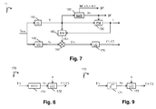
- the value Ba and/or the parameters of the non-linear function f (such as a, b, c or y) and/or the information data Inf is (are) stored in a local or remote memory and/or added into a bitstream BF as illustrated in Figs. 4 and 7 .
- a color component Ec may be obtained directly from a local or a remote memory or by applying a color transform on the HDR picture I HDR .
- Scaling by a factor can be performed by different methods, for example, by multiplying by said factor or dividing by the inverse of said factor.
- the value Y(i) of a pixel of the component Y depends un-ambiguously on the value L(i) of a pixel of the luminance component L, such that the ratio can be written as a function of L(i) only.
- This embodiment is advantageous because scaling each color component Ec by the factor r(L) that further depends on the component Y preserves the hue of the colors of the HDR picture I and thus improves the visual quality of the decoded HDR picture.
- colorfulness, chroma, and saturation refer to the perceived intensity of a specific color.
- Colorfulness is the degree of difference between a color and gray.
- Chroma is the colorfulness relative to the brightness of another color that appears white under similar viewing conditions.
- Saturation is the colorfulness of a color relative to its own brightness.
- a highly colorful stimulus is vivid and intense, while a less colorful stimulus appears more muted, closer to gray.
- a color is a "neutral" gray (a picture with no colorfulness in any of its colors is called grayscale). Any color can be described from its colorfulness (or chroma or saturation), lightness (or brightness), and hue.
- the definition of the hue and saturation of the color depends on the color space used to represent said color.
- the saturation s uv is defined as the ratio between the chroma C uv * over the luminance L* .
- the colors of the picture I2 are thus differently perceived by a human being because the saturation and the hue of the colors changed.
- the method (step 150) determines the chrominance components C1 and C2 of the picture I2 in order that the hue of the colors of the picture I2 best match the hue of the colors of the HDR picture I HDR .
- This last embodiment is advantageous because it prevents the factor from going to zero for very dark pixels, i.e. allows the ratio to be invertible regardless of the pixel value.
- step 170 the two chrominance components C1, C2 are obtained from said at least one intermediate color components E'c.
- This embodiment allows a reduction of the dynamic range according to a specific OETF but leads to a complex decoding process as detailed later.
- This embodiment is advantageous because it provides a good approximation of the OETF defined by the ITU-R recommendation BT.709 or BT.2020 and leads to a low complexity decoder.
- This embodiment is advantageous because it provides a good approximation of the OETF defined by the ITU-R recommendation BT.709 or BT.2020 but it leads to a somewhat more complex decoder than the decoder obtains when the OETF is approximated by a square-root.
- a module LC1 obtains the two chrominance components C1 and C2 by linearly combining the three intermediate components Dc:
- C 1 C 2 A 2 A 3 D 1 D 2 D 3 where A2 and A3 are the second and third rows of the 3x3 matrix A.
- Fig. 10 shows schematically a diagram of the sub-steps of the step 2040 in accordance with an embodiment of the disclosure.
- a luminance component L" and two chrominance components C"1, C"2 are obtained from the second SDR picture I SDR2 .
- the second SDR picture I SDR2 is formed by combining the second luminance component L" and the two second chrominance components C"1 and C"2 and thus those components are directly obtained from the second SDR picture I SDR2.
- a module IGM obtains a second luminance component L and two second chrominance components C1, C2 from said luminance L" and chrominance C"1, C"2 components by applying an inverse mapping on the colors obtained from said luminance L" and chrominance C"1, C"2 components.
- a module INVC obtains at least one color component Ec of the HDR picture to be decoded from said second luminance L component and said two second chrominance C1, C2 components.
- the decoded HDR picture is then obtained by combining said at least one color component Ec.
- a module ILCC obtains (step 222) the second luminance component L by linearly combining the luminance component L" and the two chrominance components C"1, C"2.
- the coefficients m and n may be those obtained by the factorization of the matrix ⁇ Ba ( L ) in equation (G), i.e. m and n are those obtained in ⁇ 0 . Consequently, they depend on the gamut of the HDR picture I (for instance BT.709 or BT.2020 gamut). Typical values for m and n are m ⁇ n in the interval [0.1,0.5]
- Equation (J) is considered as being an inverse mapping applies on the colors obtained from the luminance L" and chrominance C"1, C"2 components. Equation (J) is directly obtained from equation (A) that is considered as being a color mapping.
- the values of the second luminance component L are higher than the corresponding values of the luminance component L":
- L L ⁇ + max 0 , m C 1 ⁇ + n C 2 ⁇
- This embodiment is advantageous because it ensures that the second luminance component L does not exceed a potential clipping value that is usually used by the decoder to define a luminance peak.
- a luminance peak is required by a decoder and when the second luminance component L is given by equation (J), the second luminance component L is clipped introducing some artefacts.
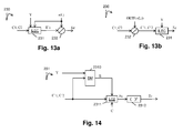
- the modulation value Ba and/or the coefficients m and n are obtained from a remote or local memory such a Look-Up-Table, or from a bitstream BF as illustrated in Fig. 11 .
- the factor ⁇ - 1 ( Ba,L ( i )) is obtained from a Look-Up-Table (LUT) for a specific modulation value Ba and a specific value L(i) of the second luminance component L.
- LUT Look-Up-Table
- a specific factor ⁇ -1( Ba , L ( i )) is stored in a LUT for each specific modulation value Ba.
- the factor ⁇ -1 ( Ba , L ( i )) for a specific modulation value Ba is obtained for a value of a pixel of the second luminance component L by interpolating the luminance peaks between the multiple luminance peaks for which LUT are stored.
- the non-linear function f - 1 is the inverse of the non-linear function f (step 130).
- the embodiments of the function f -1 are defined according to the embodiments of the function f.
- the parameters of the non-linear function f -1 (such as a, b, c or y) and/or the information data Inf is (are) obtained from a local or remote memory (for example a Look-Up-Table) and/or from a bitstream BF as illustrated in Fig. 10 .
- the non-linear function f -1 is the inverse of a gamma function.
- Y 1 L 1 / ⁇ B
- Y 1 equals Y or Y/Ba according to the embodiments of eq. (A3) or (A4)
- B is a constant value
- ⁇ is a parameter (real value strictly below 1).
- the non-linear function f -1 is the inverse of a S-Log function.
- the non-linear function f is the inverse of either a gamma correction or a SLog correction according to the pixel values of the component Y. This is indicated by the information data Inf.
- a module ILC obtains at least one color component Ec from the first component Y, the two second chrominance components C1, C2, and from a factor r(L) that depends on the second luminance component L.
- the decoded HDR picture is then obtained by combining said at least one color component Ec.
- each intermediate color component E'c the intermediate components Dc are related to the component Y, the two second chrominance components C1, C2 and the factor r(L):
- C 1 C 2 A 2 A 3 D 1 D 2 D 3
- EOTF Electro-Optical Trans Function
- OETF( E c ) D c
- ⁇ i constants depending on the matrix A
- L i linear functions also depending on the matrix A.
- a module ILEC obtains three intermediate color component E'c from the first component Y, the two second chrominance components C1, C2 and the factor r(L) as above explained.
- step 231 before step 232 is the inverse of the order, step 150 followed by step 170, of the encoding method.
- the OEFT is a square root function and the EOTF is then a square function.
- the OEFT is a cubic root function and the EOTF is then a cubic function.
- OETF x * y OETF x * OETF y
- step 232 two intermediate components C'1 and C'2 are obtained by scaling the two second chrominance components C1 and C2 by the factor OEFT(r(L(i))) where OETF is the function used in step 171 in Fig.
- a module ILEC obtains the three color components Ec from the first component Y and the two intermediate chrominance components C'1, C'2 as above explained.
- the OEFT is a square root function and the EOTF is then a square function.
- Equation (A14) is a second order equation that may be solved analytically.
- This analytic solution leads to a specific embodiment of the step 231 as illustrated in Fig. 14 .
- This embodiment is advantageous because it allows an analytic expression of the EOTF (inverse of the OETF) and thus of the decoded components of the picture.
- the EOTF is then the square function that is a low complexity process at the decoding side.
- the matrix A determines the transform of the picture I to be encoded from the color space (E1, E2, E3), in which the pixel values of the picture to be encoded are represented, to the color space (Y, C1, C2).
- Such a matrix depends on the gamut of the HDR picture to be encoded.
- the OEFT is a cube root function and the EOTF is then a cubic function.
- the decoders BLDEC and ELDEC are configured to decode data which have been encoded by the encoders BLENC and ELENC respectively.
- the encoders BLENC and ELENC are not limited to specific encoders (decoders) but when an entropy encoder (decoder) is required, an entropy encoder such as a Huffmann coder, an arithmetic coder or a context adaptive coder like CABAC used in H264/AVC or HEVC is advantageous.
- the ELENC/ELDEC may consist in using SHVC on top of a base layer codec conforming to the H.264/AVC standards ( H.264: “Advanced video coding for generic audiovisual services”, Recommendation ITU-T H.264, SERIES H: AUDIOVISUAL AND MULTIMEDIA SYSTEMS Infrastructure of audiovisual services - Coding of moving video, January 2012 .), or even to the MPEG2 standard ( MPEG2: "INFORMATION TECHNOLOGY - GENERIC CODING OF MOVING PICTURES AND ASSOCIATED AUDIO Recommendation H.262", ISO/IEC 13818-2, ISO/IEC JTC1/SC29/WG11 N0702rev, Incorporating N702 Delta of 24 March, 25 March 1994 ).
- H.264/AVC H.264: “Advanced video coding for generic audiovisual services”
- SVC Scalable Video Coding Extension of the H.264/AVC Standard
- Heiko Schwarz, Detlev Marpe, and Thomas Wiegand, IEEE TRANSACTIONS ON CIRCUITS AND SYSTEMS FOR VIDEO TECHNOLOGY, VOL. 17, NO. 9, SEPTEMBER 2007 SVC: same as above: " Overview of the Scalable Video Coding Extension of the H.264/AVC Standard", Heiko Schwarz, Detlev Marpe, and Thomas Wiegand, IEEE TRANSACTIONS ON CIRCUITS AND SYSTEMS FOR VIDEO TECHNOLOGY, VOL. 17, NO. 9, SEPTEMBER 2007 ).
- the present principles may be advantageous in that it may improve the inter-layer correlation regarding the temporal residual data respectively contained in the base layer and the enhancement layer.
- the encoders BLENC and ELENC are configured to generate a scalable bitstream F that conforms to the standard SHVC and the decoders BLDEC and ELDEC conforms to the standard SHVC.
- the modules are functional units, which may or not be in relation with distinguishable physical units. For example, these modules or some of them may be brought together in a unique component or circuit, or contribute to functionalities of a software. A contrario, some modules may potentially be composed of separate physical entities.
- the apparatus which are compatible with the disclosure are implemented using either pure hardware, for example using dedicated hardware such ASIC or FPGA or VLSI, respectively «Application Specific Integrated Circuit » «Field-Programmable Gate Array», «Very Large Scale Integration » or from several integrated electronic components embedded in a device or from a blend of hardware and software components.
- Fig. 15 represents an exemplary architecture of a device 1500 which may be configured to implement a method described in relation with Fig. 1- 14.
- Device 1500 comprises following elements that are linked together by a data and address bus 1501:
- the battery 1506 is external to the device.
- the word « register » used in the specification can correspond to area of small capacity (some bits) or to very large area (e.g. a whole program or large amount of received or decoded data).
- ROM 1503 comprises at least a program and parameters. Algorithm of the methods according to the disclosure is stored in the ROM 1503. When switched on, the CPU 1502 uploads the program in the RAM and executes the corresponding instructions.
- RAM 1504 comprises, in a register, the program executed by the CPU 1502 and uploaded after switch on of the device 1500, input data in a register, intermediate data in different states of the method in a register, and other variables used for the execution of the method in a register.
- the implementations described herein may be implemented in, for example, a method or a process, an apparatus, a software program, a data stream, or a signal. Even if only discussed in the context of a single form of implementation (for example, discussed only as a method or a device), the implementation of features discussed may also be implemented in other forms (for example a program).
- An apparatus may be implemented in, for example, appropriate hardware, software, and firmware.
- the methods may be implemented in, for example, an apparatus such as, for example, a processor, which refers to processing devices in general, including, for example, a computer, a microprocessor, an integrated circuit, or a programmable logic device. Processors also include communication devices, such as, for example, computers, cell phones, portable/personal digital assistants ("PDAs”), and other devices that facilitate communication of information between end-users.
- PDAs portable/personal digital assistants
- the HDR picture I is obtained from a source.
- the source belongs to a set comprising:
- the decoded picture is sent to a destination; specifically, the destination belongs to a set comprising:
- bitstream BF and/or F are sent to a destination.
- bitstream F and BF or both bitstreams F and BF are stored in a local or remote memory, e.g. a video memory (1504) or a RAM (1504), a hard disk (1503).
- a storage interface e.g. an interface with a mass storage, a flash memory, ROM, an optical disc or a magnetic support and/or transmitted over a communication interface (1505), e.g. an interface to a point to point link, a communication bus, a point to multipoint link or a broadcast network.
- the bitstream BF and/or F is obtained from a source.
- the bitstream is read from a local memory, e.g. a video memory (1504), a RAM (1504), a ROM (1503), a flash memory (1503) or a hard disk (1503).
- the bitstream is received from a storage interface, e.g. an interface with a mass storage, a RAM, a ROM, a flash memory, an optical disc or a magnetic support and/or received from a communication interface (1505), e.g. an interface to a point to point link, a bus, a point to multipoint link or a broadcast network.
- device 1500 being configured to implement an encoding method described in relation with Fig. 1 , 4-9, belongs to a set comprising:
- device 1300 being configured to implement a decoding method described in relation with Fig. 2 , 10-14, belongs to a set comprising:
- the device A comprises means which are configured to implement a method for encoding an picture as described in relation with the Fig. 1 , 4-9 and the device B comprises means which are configured to implement a method for decoding as described in relation with Fig. 2 , 10-14.
- the network is a broadcast network, adapted to broadcast still pictures or video pictures from device A to decoding devices including the device B.
- Implementations of the various processes and features described herein may be embodied in a variety of different equipment or applications.
- Examples of such equipment include an encoder, a decoder, a post-processor processing output from a decoder, a pre-processor providing input to an encoder, a video coder, a video decoder, a video codec, a web server, a set-top box, a laptop, a personal computer, a cell phone, a PDA, and any other device for processing a picture or a video or other communication devices.
- the equipment may be mobile and even installed in a mobile vehicle.
- a computer readable storage medium can take the form of a computer readable program product embodied in one or more computer readable medium(s) and having computer readable program code embodied thereon that is executable by a computer.
- a computer readable storage medium as used herein is considered a non-transitory storage medium given the inherent capability to store the information therein as well as the inherent capability to provide retrieval of the information therefrom.
- a computer readable storage medium can be, for example, but is not limited to, an electronic, magnetic, optical, electromagnetic, infrared, or semiconductor system, apparatus, or device, or any suitable combination of the foregoing. It is to be appreciated that the following, while providing more specific examples of computer readable storage mediums to which the present principles can be applied, is merely an illustrative and not exhaustive listing as is readily appreciated by one of ordinary skill in the art: a portable computer diskette; a hard disk; a read-only memory (ROM); an erasable programmable read-only memory (EPROM or Flash memory); a portable compact disc read-only memory (CD-ROM); an optical storage device; a magnetic storage device; or any suitable combination of the foregoing.
- the instructions may form an application program tangibly embodied on a processor-readable medium.
- Instructions may be, for example, in hardware, firmware, software, or a combination. Instructions may be found in, for example, an operating system, a separate application, or a combination of the two.
- a processor may be characterized, therefore, as, for example, both a device configured to carry out a process and a device that includes a processor-readable medium (such as a storage device) having instructions for carrying out a process. Further, a processor-readable medium may store, in addition to or in lieu of instructions, data values produced by an implementation.
- implementations may produce a variety of signals formatted to carry information that may be, for example, stored or transmitted.
- the information may include, for example, instructions for performing a method, or data produced by one of the described implementations.
- a signal may be formatted to carry as data the rules for writing or reading the syntax of a described embodiment, or to carry as data the actual syntax-values written by a described embodiment.
- Such a signal may be formatted, for example, as an electromagnetic wave (for example, using a radio frequency portion of spectrum) or as a baseband signal.
- the formatting may include, for example, encoding a data stream and modulating a carrier with the encoded data stream.
- the information that the signal carries may be, for example, analog or digital information.
- the signal may be transmitted over a variety of different wired or wireless links, as is known.
- the signal may be stored on a processor-readable medium.
Priority Applications (1)
| Application Number | Priority Date | Filing Date | Title |
|---|---|---|---|
| EP15305795.5A EP3099073A1 (fr) | 2015-05-27 | 2015-05-27 | Procédé et dispositif de codage/décodage d'une image hdr et sdr dans/à partir d'un train binaire évolutif |
Applications Claiming Priority (1)
| Application Number | Priority Date | Filing Date | Title |
|---|---|---|---|
| EP15305795.5A EP3099073A1 (fr) | 2015-05-27 | 2015-05-27 | Procédé et dispositif de codage/décodage d'une image hdr et sdr dans/à partir d'un train binaire évolutif |
Publications (1)
| Publication Number | Publication Date |
|---|---|
| EP3099073A1 true EP3099073A1 (fr) | 2016-11-30 |
Family
ID=53385565
Family Applications (1)
| Application Number | Title | Priority Date | Filing Date |
|---|---|---|---|
| EP15305795.5A Withdrawn EP3099073A1 (fr) | 2015-05-27 | 2015-05-27 | Procédé et dispositif de codage/décodage d'une image hdr et sdr dans/à partir d'un train binaire évolutif |
Country Status (1)
| Country | Link |
|---|---|
| EP (1) | EP3099073A1 (fr) |
Cited By (1)
| Publication number | Priority date | Publication date | Assignee | Title |
|---|---|---|---|---|
| CN109756777A (zh) * | 2017-11-01 | 2019-05-14 | 瑞昱半导体股份有限公司 | 处理影像序列的多种格式的传送端、接收端及方法 |
-
2015
- 2015-05-27 EP EP15305795.5A patent/EP3099073A1/fr not_active Withdrawn
Non-Patent Citations (15)
| Title |
|---|
| "Advanced video coding for generic audiovisual services", RECOMMENDATION ITU-T H.264, SERIES H: AUDIOVISUAL AND MULTIMEDIA SYSTEMS INFRASTRUCTURE OF AUDIOVISUAL SERVICES - CODING OF MOVING VIDEO, January 2012 (2012-01-01) |
| "High Efficiency Video Coding", SERIES H: AUDIOVISUAL AND MULTIMEDIA SYSTEMS, RECOMMENDATION ITU-T H.265, TELECOMMUNICATION STANDARDIZATION SECT OR OF ITU, October 2014 (2014-10-01) |
| "High Efficiency Video Coding", SERIES H: AUDIOVISUAL AND MULTIMEDIA SYSTEMS, RECOMMENDATION ITU-T H.265, TELECOMMUNICATION STANDARDIZATION SECTOR OF ITU, October 2014 (2014-10-01) |
| "INFORMATION TECHNOLOGY - GENERIC CODING OF MOVING PICTURES AND ASSOCIATED AUDIO Recommendation H.262", ISO/IEC 13818-2, ISO/IEC JTC1/SC29/WG11 N0702REV, 24 March 1994 (1994-03-24) |
| BORDES PHILIPPE ET AL: "Color Gamut Scalable Video Coding For SHVC", 2013 PICTURE CODING SYMPOSIUM (PCS), IEEE, 8 December 2013 (2013-12-08), pages 301 - 304, XP032567015, DOI: 10.1109/PCS.2013.6737743 * |
| FABRICE LE LÉANNEC ET AL: "Modulation channel information SEI message (JCTVC-R0139r2)", 2 July 2014 (2014-07-02), XP055225001, Retrieved from the Internet <URL:http://phenix.int-evry.fr/jct/doc_end_user/documents/18_Sapporo/wg11/JCTVC-R0139-v6.zip> [retrieved on 20151102] * |
| HEIKO SCHWARZ; DETLEV MARPE; THOMAS WIEGAND, IEEE TRANSACTIONS ON CIRCUITS AND SYSTEMS FOR VIDEO TECHNOLOGY, vol. 17, no. 9, September 2007 (2007-09-01) |
| HEIKO SCHWARZ; DETLEV MARPE; THOMAS WIEGAND: "Overview of the Scalable Video Coding Extension of the H.264/AVC Standard", IEEE TRANSACTIONS ON CIRCUITS AND SYSTEMS FOR VIDEO TECHNOLOGY, vol. 17, no. 9, September 2007 (2007-09-01) |
| LASSERRE S ET AL: "Single layer low-bit depth EDR video coding with SDR/HDR backward compatibilities", 111. MPEG MEETING; 6-2-2015 - 20-2-2015; GENEVA; (MOTION PICTURE EXPERT GROUP OR ISO/IEC JTC1/SC29/WG11),, no. m36083, 17 February 2015 (2015-02-17), XP030064451 * |
| LE LÃ CR ANNEC F ET AL: "Usage of modulation channel for high bit-depth signal encoding", 18. JCT-VC MEETING; 30-6-2014 - 9-7-2014; SAPPORO; (JOINT COLLABORATIVE TEAM ON VIDEO CODING OF ISO/IEC JTC1/SC29/WG11 AND ITU-T SG.16 ); URL: HTTP://WFTP3.ITU.INT/AV-ARCH/JCTVC-SITE/,, no. JCTVC-R0267, 26 June 2014 (2014-06-26), XP030116574 * |
| P. BORDES ET AL.: "Color Gamut Scalable Video Coding for SHVC", PCS, IEE, 2013 |
| REC. ITU-R BT.2020-1, June 2014 (2014-06-01) |
| REC. ITU-R BT.709-5, April 2002 (2002-04-01) |
| SÉBASTIEN LASSERRE ET AL: "Single layer low-bit depth EDR video coding with SDR/HDR backward compatibilities (m36083) - Presentation Slides", 111. MPEG MEETING; 6-2-2015 - 20-2-2015; GENEVA; (MOTION PICTURE EXPERT GROUP OR ISO/IEC JTC1/SC29/WG11),, 17 February 2015 (2015-02-17), XP055224796, Retrieved from the Internet <URL:http://wg11.sc29.org/> [retrieved on 20151030] * |
| YAN YE; ANDRIVON, P: "The Scalable Extensions of HEVC for Ultra-High-Definition Video Delivery", MULTIMEDIA, IEEE, vol. 21, no. 3 |
Cited By (2)
| Publication number | Priority date | Publication date | Assignee | Title |
|---|---|---|---|---|
| CN109756777A (zh) * | 2017-11-01 | 2019-05-14 | 瑞昱半导体股份有限公司 | 处理影像序列的多种格式的传送端、接收端及方法 |
| CN109756777B (zh) * | 2017-11-01 | 2021-10-12 | 瑞昱半导体股份有限公司 | 处理影像序列的多种格式的传送端、接收端及方法 |
Similar Documents
| Publication | Publication Date | Title |
|---|---|---|
| US11178412B2 (en) | Method and apparatus of encoding and decoding a color picture | |
| US20180352257A1 (en) | Methods and devices for encoding and decoding a color picture | |
| EP3251336B1 (fr) | Procédé et dispositif de mise en correspondance de couleurs entre images en couleur de plage dynamique différente | |
| US11006151B2 (en) | Method and device for encoding both a HDR picture and a SDR picture obtained from said HDR picture using color mapping functions | |
| EP3051489A1 (fr) | Procédé et appareil de codage et de décodage d'une image couleur | |
| US20180014024A1 (en) | Method and apparatus of encoding and decoding a color picture | |
| EP3099073A1 (fr) | Procédé et dispositif de codage/décodage d'une image hdr et sdr dans/à partir d'un train binaire évolutif | |
| EP3051792A1 (fr) | Procédé et dispositif de mise en correspondance de couleurs entre images en couleur de plage dynamique différente |
Legal Events
| Date | Code | Title | Description |
|---|---|---|---|
| PUAI | Public reference made under article 153(3) epc to a published international application that has entered the european phase |
Free format text: ORIGINAL CODE: 0009012 |
|
| AK | Designated contracting states |
Kind code of ref document: A1 Designated state(s): AL AT BE BG CH CY CZ DE DK EE ES FI FR GB GR HR HU IE IS IT LI LT LU LV MC MK MT NL NO PL PT RO RS SE SI SK SM TR |
|
| AX | Request for extension of the european patent |
Extension state: BA ME |
|
| STAA | Information on the status of an ep patent application or granted ep patent |
Free format text: STATUS: THE APPLICATION IS DEEMED TO BE WITHDRAWN |
|
| 18D | Application deemed to be withdrawn |
Effective date: 20170531 |