EP3113124A1 - Liftvorrichtung, warenautomat - Google Patents
Liftvorrichtung, warenautomat Download PDFInfo
- Publication number
- EP3113124A1 EP3113124A1 EP16168290.1A EP16168290A EP3113124A1 EP 3113124 A1 EP3113124 A1 EP 3113124A1 EP 16168290 A EP16168290 A EP 16168290A EP 3113124 A1 EP3113124 A1 EP 3113124A1
- Authority
- EP
- European Patent Office
- Prior art keywords
- loading compartment
- goods
- vending machine
- loading
- tilted
- Prior art date
- Legal status (The legal status is an assumption and is not a legal conclusion. Google has not performed a legal analysis and makes no representation as to the accuracy of the status listed.)
- Granted
Links
Images


Classifications
-
- G—PHYSICS
- G07—CHECKING-DEVICES
- G07F—COIN-FREED OR LIKE APPARATUS
- G07F11/00—Coin-freed apparatus for dispensing, or the like, discrete articles
- G07F11/02—Coin-freed apparatus for dispensing, or the like, discrete articles from non-movable magazines
- G07F11/38—Coin-freed apparatus for dispensing, or the like, discrete articles from non-movable magazines in which the magazines are horizontal
- G07F11/42—Coin-freed apparatus for dispensing, or the like, discrete articles from non-movable magazines in which the magazines are horizontal the articles being delivered by motor-driven means
-
- G—PHYSICS
- G07—CHECKING-DEVICES
- G07F—COIN-FREED OR LIKE APPARATUS
- G07F11/00—Coin-freed apparatus for dispensing, or the like, discrete articles
- G07F11/02—Coin-freed apparatus for dispensing, or the like, discrete articles from non-movable magazines
- G07F11/04—Coin-freed apparatus for dispensing, or the like, discrete articles from non-movable magazines in which magazines the articles are stored one vertically above the other
- G07F11/16—Delivery means
-
- G—PHYSICS
- G07—CHECKING-DEVICES
- G07F—COIN-FREED OR LIKE APPARATUS
- G07F11/00—Coin-freed apparatus for dispensing, or the like, discrete articles
- G07F11/46—Coin-freed apparatus for dispensing, or the like, discrete articles from movable storage containers or supports
- G07F11/58—Coin-freed apparatus for dispensing, or the like, discrete articles from movable storage containers or supports the articles being supported on or by endless belts or like conveyors
Definitions
- the present invention relates to a lifting device for a vending machine, a vending machine with such a lifting device and a method for operating such a vending machine.
- a transparent disc is provided on the front of the vending machine, behind which the goods are visible, usually standing, arranged in goods magazines.
- Such goods magazines usually have a plurality of juxtaposed goods compartments.
- a plurality of goods magazines is usually provided, which are arranged one above the other.
- the goods can be issued for example by a provided in the goods compartments spiral drive, a linear slide or other feed mechanism from the individual goods compartments.
- a transfer system a so-called lift, is used for the more controlled transfer of the goods from a goods compartment to an output device.
- Such a transfer system is for example in the EP 2 232 451 B1 described.
- This has two configurations of transfer means, the transfer means in a first configuration having a concave shape in which products dispensed from a goods compartment are held, and in a second configuration the goods freely falling out of the transfer means into an exit.
- the present invention has for its object to provide an improved lift device.
- this object is achieved by a lifting device with the features of claim 1 and / or by a vending machine with the features of claim 8 and / or by a method having the features of claim 13.
- the idea underlying the present invention is a loading compartment mounted on a carriage to provide a tilting axis extending in the depth direction tiltable. This enables a smooth depositing of goods in an output device. At the same time this allows a realization with a very simple mechanism or kinematics, which in particular requires no additional drives, lever, additional joints or the like.
- the carriage is preferably arranged laterally on the lift device and preferably runs in a vertically extending guide.
- the loading compartment extends from the carriage in the straight position along a transverse direction, in particular parallel to a goods magazine.
- the loading compartment extends over the entire width of the goods magazine.
- the loading compartment can also be provided narrower and / or additionally movable in the transverse direction.
- a carriage is understood to mean a carriage running in the guide, which is driven either externally, for example via a belt or chain drive, or internally, for example by means of an integrated motor.
- a linear drive of the carriage in the guide is conceivable.
- Under a height direction is preferably a vertical direction to understand.
- a transverse direction or width direction of the loading compartment is preferably to be understood as meaning a horizontal direction, which corresponds in particular to the width direction of a goods magazine, and along which the goods compartments are arranged next to one another. In a vending machine, this usually corresponds at the same time to the horizontal direction in the plane of the front or the transparent front window.
- the front of the vending machine, the goods magazine and the loading tray in the horizontal transverse direction are preferably parallel to each other.
- a horizontal position of the loading compartment is to be understood as meaning a straight position of the loading compartment.
- a depth direction is preferably to be understood as meaning a likewise horizontal direction which runs transversely to the transverse direction (or width direction) within a horizontal plane.
- the height direction, the transverse direction and the depth direction are thus preferably perpendicular to each other and thus span an orthogonal directional system.
- the invention is not limited to this, but deviations from orthogonality of directions are also included.
- manufacturing tolerances and deviations are included within the scope of a setting range or in the context of a professional interpretation of the height, transverse and depth direction.
- Conceivable are slight deviations in the direction of up to a maximum of 45 °, preferably in the range of less than 10 °.
- transverse and depth directions are also to be understood as directions which, if appropriate, run slightly obliquely to a horizontal plane and / or extend at an angle to one another which deviates slightly from a right angle. The same applies analogously for a straight position of the loading compartment.
- the height direction is also to be understood as meaning directions that are slightly oblique to the vertical in a vertical plane.
- a tilt axis is to be understood as an axis around which the loading compartment can be tilted as required.
- the goods compartment can be tilted freely, that is to say gravity-accelerated.
- the tilting axis extending in the depth direction is particularly advantageous, because the shape of the loading compartment is due to the width of the goods magazine usually elongated along the horizontal transverse direction and only laterally mounted on the carriage.
- a gravity-accelerated tilting is thus advantageously a maximum lever arm available, so that the tilting can run reliably.
- the invention is not limited to gravity-accelerated tilting. Rather, in addition, a biasing spring biasing the tilt axis in the straight position of the loading compartment may be provided to assist the tilting in the tilted position. Furthermore, a motor-driven tilting is conceivable. For example, a tilting motor may be provided for this purpose, which is integrated in particular in the carriage or in the loading compartment.
- a latching mechanism for releasably locking the loading compartment in the straight position is provided on the carriage and optionally or additionally on another carriage.
- the loading compartment is in the straight position, which preferably represents a horizontal position, releasably held or fixed by the latching mechanism.
- the locking mechanism is easily released or released.
- the locking mechanism may be provided on the same carriage as the tilting axis or on a second or further, parallel running carriage.
- a release means for releasing the latching mechanism is provided in a predetermined position of the carriage, in particular in a deepest position of the carriage in the height direction.
- the latching mechanism is provided and designed to be unlocked when released by the triggering means, so that the loading compartment can be tilted about the tilting axis oriented in the depth direction.
- the loading tray is thus tilted at a predetermined position, so that it passes the goods, for example, to an output device of a vending machine.
- the loading compartment is tilted freely, ie it tilts solely due to its gravity from the horizontal position to the tilted position.
- the triggering means may be designed, for example, mechanically as a locking mechanism unlocking pin or the like.
- the triggering means can also be designed as an electrical contact which effects an electrical or electrically driven unlocking of the latching mechanism.
- a non-contact triggering means is also conceivable, for example in the form of a Hall sensor in conjunction with a control device which activates an actuator on the latching mechanism in response to input of a predetermined signal of the Hall sensor for releasing the latching mechanism.
- the tilting axis is arranged in the region of the bottom of the loading compartment. It is thus advantageously ensured that when loading the loading compartment on a horizontal surface, the loading compartment assumes a straight or horizontal position. Furthermore, it is thus ensured that the width of the loading compartment in the released state of the latching mechanism is not increased by tilting. This ensures that the loading compartment does not tilt or lock with other components when tilted. In particular, when the loading tray is tilted in a retracted state in a dispenser state is thus ensured that the loading tray and the output device do not interfere with each other, since the loading tray does not swing outwards during tilting.
- the tilting axis has a stop.
- the loading compartment may also have a stop.
- the stop limits the tilting of the loading compartment to a maximum tilt angle relative to the transverse direction.
- the maximum tilt angle is less than 90 °, so that a return of the loading compartment in a straight or horizontal Position is possible by placing on a substantially transverse or horizontal ground.
- the loading compartment would be tilted in the wrong direction when placing.
- reasonable maximum tilt angles are 85 ° maximum.
- the Verkippwinkel should not be less than 50 °.
- a good compromise between recoverability and reliability of transfer is achieved in the range of 60 ° to 70 °.
- a reasonable range of the maximum tilt angle between 50 ° and 85 °, preferably between 60 ° and 70 °.
- the latching mechanism is provided by returning the loading tray locked in the straight position.
- the loading compartment For latching the locking mechanism, ie for fixing the loading compartment in the straight, especially horizontal, position, the loading compartment thus needs to be brought only in the straight position.
- the return of the loading tray in the straight position is preferably effected by placing the tilted loading tray on a substrate, in particular a horizontal surface, and moving the carriage in the direction of the ground until the straight position of the loading tray is reached again.
- the loading compartment slides off the ground.
- sliding means for example a roller or a friction-reduced curved surface, may be provided for this purpose.
- a respective carriage is provided at the transverse ends of the loading compartment.
- the loading compartment is either formed in one piece or formed divided into a first and a second half.
- the first half is tiltably mounted on a first carriage about a first tilt axis oriented in the depth direction.
- the second half is tiltably mounted on a second carriage about a second tilt axis oriented in the depth direction.
- the first and second carriages are preferably provided on two parallel, in particular vertical, guides, each extending at a transverse end of the loading compartment in the vertical direction and are preferably designed as rails.
- the loading compartment can also be formed in one piece.
- the loading compartment is tiltably mounted only at a transverse end to a carriage, which is provided in a vertically extending guide.
- a carriage which is provided in a vertically extending guide.
- a second in a parallel second guide running Lauschlitten provided on which the locking mechanism is provided.
- only a single carriage may be provided, on which in addition to the tilting axis and the latching mechanism is provided.
- the loading compartment of the lift device is provided for the transfer of the goods into the dispensing device.
- the dispensing device is designed to be open or openable in an area facing the goods magazines, in particular on an upper side of the dispensing device, so that the loading compartment can enter the dispensing device through the opening. This has the particular advantage that the product does not fall over the height of the dispenser into the same, but can be stored gently within the dispenser.
- the loading compartment moves to transfer the goods to the bottom of the dispenser.
- the release means are arranged such that the latching mechanism is released only after retraction of the loading compartment in the output device.
- the release means release the locking mechanism only when the loading compartment has reached a bottom of the dispenser.
- the transfer of the goods to the output device is done by tilting the loading tray when moving out of the loading tray from the output device. During the transfer of the goods, therefore, the same does not fall out of the tilted or opened loading compartment, but remains, apart from a residual height between the bottom of the loading compartment and the bottom of the dispensing device, essentially at the same height while the loading compartment is tilted. When tilting the loading compartment creates a gap or opening through which the goods can slide into the dispenser, without that it moves much in the vertical direction.
- an unwanted dropping of the product is thus effectively avoided. This ensures that the goods are not damaged, worsened or undesiredly shaken. Conceivable but not necessary is this one completely placing the bottom of the loading tray on the bottom of the dispenser before releasing the latching mechanism to minimize any residual amount therebetween.
- the output device has a movable securing device.
- This is in particular designed as a movable partitioning element, a so-called shutter.
- the security device is designed and provided to secure in a closed state the area of the goods magazines in the output of a product from the dispenser against unauthorized access, in particular against a theft and / or vandalism. It is also provided in an open state to allow retraction of the loading tray in the dispenser.
- the securing device is for this purpose on a provided in the output device opening movable, preferably rotatable, provided so that it closes the opening in the closed state and releases in the open state for retracting the loading compartment.
- the securing device is provided on its side facing the goods magazines in the closed position as a base for placing the tilted loading tray and returning the loading tray in the straight position and designed.
- the safety device in the closed state in a transverse direction, in particular horizontally, extending surface or slideway, on which the tilted loading compartment can slide.
- the return is carried out accordingly by moving the carriage in the direction of the securing device, ie in the height direction down, the loading compartment slides on the securing device and thus guided in the straight, in particular horizontal position becomes.
- the locking mechanism Upon reaching the straight position of the locking mechanism is automatically locked.
- the loading compartment moves into the dispenser for the transfer of the goods.
- the loading compartment moves in so far that it touches a bottom of the dispenser.
- the loading compartment is tilted out of the dispenser when moving out.
- the loading compartment freely tilts, i. by his gravity.
- the goods are transferred to the dispensing device by forming a gap or opening during tilting, through which the goods then slides into the dispenser.
- the goods are not substantially displaced when tilting the loading compartment in the vertical direction, so that the goods do not fall out of the loading compartment when they are handed over, but are deposited gently in the dispensing device.
- a latching mechanism is released for tilting the loading compartment.
- the latching mechanism is provided by returning the loading tray from a tilted position to a straight position latched again. This happens in particular by placing the tilted loading compartment on a substrate.
- the straight position corresponds in particular to a horizontal position of the loading compartment.
- Preferably serves as a subsurface a foreclosure element of the output device.
- the partition member is moved to a retracted state after moving out of the loading tray from the dispenser. Subsequently, the loading compartment placed on the closed partition element for returning to the straight position.
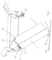
- Fig. 1 shows a lift device 1 according to a first embodiment. It is a lift device 1 with a one-piece loading compartment. 2
- the lift device 1 also has two opposite running carriages 3, on which the loading compartment 2 is mounted.
- the carriages 3 each run in a guide 13 designed as a vertical running rail, which are each arranged on a transverse side of the lifting device 1.
- the loading compartment in a vertical height direction 4 is adjustable.
- the loading compartment 2 In the illustrated straight or horizontal orientation of the loading compartment 2, this extends in the horizontal transverse direction 5 between the two carriages 3.
- the loading compartment 2 is mounted on a carriage 3 via a tilt axis 6 extending in a vertical depth direction and over at a further opposite carriage 3 a latching latching mechanism 7 is kept locked in the straight position.
- the carriages 3 are the same direction, for example, each via a motor-driven cable, not shown.
- a drive via an integrated respectively in the carriage 3 motor or via an integrated respectively in the guides 13 and the carriage 3 linear drive is possible.
- Fig. 2 shows the lift device 1 according to Fig. 1 with tilted loading compartment 2.
- the illustrated tilted position of the loading compartment 2 is ingestible when the latching mechanism 7 is released, so that a provided on the loading compartment 2 locking latch 14 is released by the latching mechanism 7 and the loading compartment 2 can tilt freely about the tilting axis 6.
- the latching mechanism 7 is designed such that a return of the loading compartment 2 in the straight position causes a latching of the latching mechanism 7.
- the tilting axis 6 is realized by means of a provided in the region of a bottom 9 of the loading compartment 2 hinge 15, which allows free tilting of the loading compartment 2 relative to the carriage 3, when the locking mechanism 7 is released.
- Fig. 3 shows a detailed view of a loading compartment 2 of a lift device 1 according to Fig. 1 and 2 in a straight position.
- the locking mechanism 7 is clearly recognizable therein, which comprises the said latching bolt 14 and a spring-biased latching projection 16. If the loading compartment 2 is moved along the vertical height direction 4, the latching mechanism 7 strikes a predetermined point at which the loading compartment 2 is to be tilted, in particular a lowest position or transfer position of the loading compartment to a triggering means 8.
- the triggering means is shown schematically here a release pin 8 is shown.
- the release pin 8 is arranged such that it presses the detent projection 16 against its spring bias in processes of the loading compartment 2 in a corresponding position, without blocking the latching bolt 14.
- the release pin 8 presses the locking projection 16 the latching bolt 14 is released, so that the loading compartment 2 can be freely tilted about the tilting axis 6.
- Fig. 4 shows a detailed view of the loading compartment 2 according to Fig. 3 in a tilted position.
- the loading compartment 2 is guided during tilting in a guide groove 17.
- the guide groove 17 has a stop 10 which limits or defines the maximum tilt angle about the tilting axis 6 to 70 °.
- a roller 18 arranged in the region of the latching bolt 14 is provided, which is designed to a below the loading tray 2 arranged to unroll here only schematically subscribed base 19 when the two carriages 3 in the vertical height direction 4 move down.
- the loading compartment 2 is tilted in further process of the carriage 3 in the height direction 4 down to the tilt axis 6 back into the straight or horizontal position.
- the locking latch 14 engages the locking projection 16, so that the locking mechanism 7 is locked again.
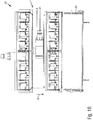
- Fig. 5 shows a lift device 1 according to a second embodiment.
- This lift device 1 has a split loading compartment 2 with a first half 11 and a second half 12.
- the first half 11 is tiltably mounted on a first running carriage 3a running in a first guide rail 13a designed as a running rail via a first tilting axis 6a extending in the horizontal depth direction.
- the second half 12 is tiltably mounted on a second running carriage 3b running in a second guide 13b designed as a running rail via a second tilting axis 6b extending in the horizontal depth direction.
- Each of the carriages 3a, 3b has a latching mechanism 7a or 7b, which is not shown here in detail for clarity. It is a function of the latching mechanism 7 of the first embodiment according to Fig. 1 to 4 substantially analogous latching mechanism, with the difference that the respective tilting axis 6a and 6b and the respective latching mechanism 7a and 7b are respectively provided here on the same carriage 3a and 3b. Accordingly, also not shown Release means 8a, 8b provided on both sides of the lift device 1 at a predetermined position at which the two halves 11, 12 of the loading compartment 2 are to be tilted.
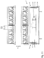
- Fig. 6 shows the lift device 1 according to Fig. 5 with tilted loading compartment 2.
- the two halves 11, 12 of the loading compartment 2 are tilted about their respective associated tilting axis 6a and 6b in a tilted position.
- stop 10 for each of the halves 11, 12 of the loading compartment 2 is provided to limit the tilt angle to 70 °.
- the two halves 11, 12 of the loading compartment 2 in an analogous manner as the loading compartment 2 according to the first embodiment in the straight position
- the two halves 11, 12 of the loading compartment 2 in an analogous manner as the loading compartment 2 according to the first embodiment in the straight position
- rollers or alternatively sliding surfaces or the like in the region of the bottom 9a, 9b of the two halves 11, 12 may be provided.
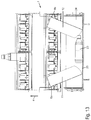
- Fig. 7 shows a schematic representation of a vending machine 20 in a starting position.
- the vending machine 20 is here schematically for clarity without a housing and shown without a front panel or front screen. Furthermore, the guides or rails 13a, 13b of the lift device 1 are hidden.
- the vending machine 20 has a plurality of goods magazines 21, which are arranged one above the other in the vertical height direction 4. Only two superimposed goods magazines 21 are shown by way of example, but any desired variety of goods magazines 21 adapted to the size of the vending machine 20 and to the height of the goods 23 can be arranged one above the other.
- the vending machine 20 has a lift device 1. This is exemplary here according to the second embodiment of the Figures 5 and 6 shown with a two-part loading compartment. However, it may also be a lift device 1 according to the first embodiment of the FIGS. 1 to 4 act with one-piece loading compartment. The following functional description or the method described below for operating the vending machine is thus analogous to a vending machine with a lift device 1 according to the first embodiment transferable.
- the vending machine 20 also has an output device 24. In the illustrated embodiment, this is a so-called output drum.
- the stacked goods magazines 21 each have a plurality of juxtaposed goods compartments 22.
- any desired size of the vending machine 20 and to the width of the goods 23 adapted plurality of goods compartments 22 may be provided side by side.
- Each goods compartment 22 is provided with a conveying device for dispensing a product 23 into the loading compartment 2.
- a conveying device for dispensing a product 23 into the loading compartment 2.
- This may, for example, be a conveyor spiral, a spiral drive or a linearly movable slide.
- a retaining spring is provided at a front end of each article compartment 22, which prevents inadvertent dispensing of a product 23.
- Fig. 7 is shown as a goods compartment 22 goods 23 exemplified a beverage bottle.
- the commodity 23 could also be any other commodity, such as a soda can, a wrapped or bagged food or beverage, or non-food items such as cigarette packets, bicycle tubes, or other products.
- a control device which serves the vending machines, in particular the drives of the vending machine, during operation, in particular a user input, controls accordingly.
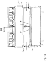
- Fig. 8 shows a side view of a portion of the vending machine 20 according to Fig. 7 ,
- the section shown has a goods magazine 21, the lift device 1 and the output device 24.
- the lift device 1 or its loading compartment 2 is analogous to the in Fig. 7 shown retracted position in the output device 24.
- a securing device 26 a so-called shutter, in the form of a movable partition element 26 is provided which, in the illustrated open state, permits retraction of the loading compartment 2 into the output device 24.
- a closed state of the partition element 26 is ingestible when the loading compartment 2 has moved out of the dispenser 24.
- the closed state is then achieved by a motor-driven rotation of the partitioning element 26 about an axis of rotation 27.
- the partition member 26 obstructs the opening of the dispenser 24 to the goods magazines 21.
- the area of the commodity magazines 21 is inaccessible from the dispenser 24.
- the mechanism of the partitioning element 26 will be described in relation to FIGS FIGS. 19 to 26 discussed in more detail.
- Fig. 9 shows the vending machine 20 according to Fig. 7 in a Abhohlposition the lift device 1.
- the loading tray 2 is moved out of the output device 24 in the vertical height direction 4 upwards and arranged at the level of a goods magazine 21.
- the lift device 1 is ready in this position, one in a goods compartment 22 of the goods magazine 21 stored goods 23 when it is issued from the goods compartment 22.
- Fig. 10 shows the vending machine 20 according to Fig. 9 If the goods 23, as shown, received in the loading compartment 2, the lift device 1 can be moved in the vertical height direction 4 down to the output device 24 to the goods 23 to the output device 24 to hand over.
- Fig. 11 shows the vending machine 20 according to Fig. 10
- a transfer position of the lift device 1 in this transfer position the lift device 1 or its loading compartment 2 in the vertical height direction 4 down to the output device 24 is moved.
- the goods 23 can be transferred to the output device 24.
- Fig. 12 shows the vending machine 20 according to Fig. 11 in the transfer position with released latching mechanism 7a, 7b.
- the latching mechanism 7a, 7b is released, the two halves 11, 12 of the loading compartment 2 can be freely tilted about their respective tilting axis 6a, 6b.
- the halves 11, 12 of the loading compartment 2 set on a bottom 25 of the dispenser 24.
- the halves 11, 12 of the loading compartment 2 continue to tilt about their respective tilting axis 6a, 6b, whereby the goods can be transferred to the delivery device 24 in a gentle manner ,
- Fig. 13 shows the vending machine 20 according to Fig. 12 when moving out of the lift device 1 from the output device 24 for transfer of the goods 23.
- the halves 11, 12 When moving out of the loading compartment 2 from the output device 24, the halves 11, 12 further tilt about their respective tilt axis 6a, 6b. In this case, the goods 23 slide on the halves 11, 12 of the loading compartment 2, so that the goods 23 gently, that is stored without falling on the floor 25 of the output device 24.
- Fig. 14 shows the vending machine 20 according to Fig. 13 in a tilted, moved out of the dispenser 24 position of the lift device 1.
- the lift device 1 is completely moved out of the dispenser 24. That is to say, the halves 11, 12 of the loading compartment 2 are also completely moved out of the delivery device 24 in the tilted position together with their lowest edge, so that the delivery device 24 can now be closed by means of the partitioning element 26.
- Fig. 15 shows the vending machine 20 according to Fig. 14 in an output position of the output device with closed partition 26.
- the halves 11 and 12 of the loading compartment 2 can be returned to their straight or horizontal position by the carriages 3a and 3b of the lift device 1 are moved in the vertical height direction 4 downwards in the direction of the partition element 26.
- the tilted halves 11, 12 of the loading compartment 2 set on the foreclosure element 26.
- the partition element 26 thus serves as a base on which the loading compartment 2 or its two halves 11 and 12 slide off and so around their respective Tilting axis 6a, 6b are tilted back into the straight position, as indicated by the arrows.
- Fig. 16 shows the vending machine 20 according to Fig. 15 after returning the loading tray 2 from the tilted position to a straight position.
- the product 23 has already been removed from the dispensing device 24, so that it is now empty.
- the loading compartment 2 has moved so far in the direction of the partitioning element 26 that it completely rests with its entire floor 9 or that the two halves 11, 12 of the loading compartment 2 with their respective floors 9a, 9b rest on the partitioning element 26. In this straight position, the respective latching mechanism 7a, 7b associated with the halves 11 and 12 of the loading compartment 2 is locked. The loading compartment 2 is now releasably locked again in the straight position.
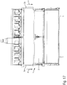
- Fig. 17 shows the vending machine 20 according to Fig. 16 with open partition element 26 of the output device 24.
- the partition element 26 is by rotation about the rotation axis 28 back in the in Fig. 8 shown opened state.
- the lift device 1 can now be moved back to the starting position, in which the carriages 3a, 3b are moved in the vertical height direction 4 downward.
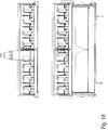
- Fig. 18 shows the vending machine 20 according to Fig. 17 with retracted to the initial position lift device 1.
- the assumed starting position corresponds to the in Fig. 7 represented original starting position.
- the loading compartment is moved by moving the carriages 3a, 3b in the vertical height direction 4 down into the dispensing device 24.
- the method for operating the vending machine 20 has now gone through a complete cycle. Upon request of another true product 23, the process for operating the vending machine commences again accordingly.
- Fig. 19A shows a perspective view of an output device 24.
- the output device 24 has a rotatable output drum 28 and an adjustable partition member 26. Furthermore, a drive device 31 is provided for adjusting the partitioning element 26 and for rotating the output drum 28.
- the dispensing drum 28 can be rotated between a pick-up position and an issue position. Shown is the output drum 28 in Fig. 19A the recording position. The output drum 28 is formed in the receiving position for receiving a product, not shown, and in the dispensing position for dispensing the product, not shown.
- an opening 29 is provided on the dispensing drum 28.
- the opening 29 is located on a receiving area 30, in which a product can be received.
- a product can be received, which is transferred from the loading compartment 2 of the lift device in the output device 24.
- the partition member 26 is provided and formed in an open position for releasing the receiving portion 30 and in a closed position for locking the receiving portion 30 inaccessible. Shown is the foreclosure element 26 in Fig. 19A in the open position.
- the partition element 26 is adjustable by the drive device 31 in the closed position, with reference to Fig. 19B will be discussed in more detail.
- the dispensing drum 28 is rotatable by the drive device 31 in the dispensing position. However, this is only possible if previously the partition element 26 is moved to the closed position.
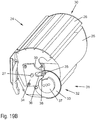
- Fig. 19B shows the output device according to Fig. 19A with adjusted in a closed position foreclosure element 26.
- the receiving area 30 is inaccessible blocked in the closed position of the partition 26.
- Both the partition element 26 and the output drum 28 are rotatably mounted on a common axis of rotation 27 independently of one another. Accordingly, the partition member 26 can be adjusted by means of the drive device 31 by rotating about the rotation axis 27.
- the drive device 31 comprises a drive mechanism 32, which has a transmission element 33.
- the translation element 33 can be driven via a gear provided on the circumference of the transmission element 33 with a drive, not shown. For example, meshes with a pinion of the drive with the teeth of the translation element 33rd
- the output drum 28 is not open manually, it is driven by a mechanical control cam by the same drive as the partition element 26 via the transmission element 33 by a motor.
- a torque limit in the form of a slip clutch or in the form of a sensory detection of the torque and a corresponding control, which shuts off at a predetermined maximum torque realized.
- a control can be realized such that in the event that the drive does not reach its intended end position during rotation of the dispensing drum or during adjustment of the partitioning element within a certain time, it is assumed that something has been trapped in the flap and the drive therefore retracted becomes.
- the translation element 33 is designed to interact with a first contact section 34 provided on the partition element 26.
- the translation element 33 has a first pin 35.
- the first contact portion 34 of the partition element 26 has for this purpose a first guide 36, in which the first pin 35, depending on the position of the transmission element 33 can intervene temporarily.
- the partition 26 is adjustable between the closed and the open position. In the illustrated embodiment performs in an open position of the partition element 26 according to Fig. 19A a rotation of the transmission element 33 in a clockwise direction to an adjustment of the partition element 26 by a rotation about the rotation axis 27 in the counterclockwise direction.
- the transmission element 33 has a first running cam 37.
- the first contact section 34 of the partitioning element 26 has a corresponding first trained running surface 38 and also corresponding thereto trained second tread 39.
- the first running surface 38 is arranged such that upon engagement of the first running cam 37 in the first running surface 38, a locking of the partitioning element 26 takes place in the closed position. Such a situation is Fig. 19B shown.
- the second running surface 39 is arranged such that upon engagement of the first running cam 37 in the second running surface 39, a locking of the partitioning element 26 takes place in the open position. Such a situation in Fig. 19A shown.
- the first pin 35 and the first barrel cam 37 are each at a same, in Fig. 19B shown side of the translation element 33 is arranged.
- the translation element 33 on the opposite side of a second pin 40 and a second barrel cam 41.
- the output drum 28 has a second contact section 42 concealed by the partition element 26.
- Fig. 20 shows a detailed view of a drive mechanism 32 with marked hidden edges. In the following the associated hidden sections or parts are described.
- the translation member 33 is also formed with the provided on the output drum 28 second contact portion 42 to interact and has to the second pin 40.
- the second contact portion 42 of the output drum 28 has for this purpose a second guide 43, in which the second pin 40 can intervene temporarily depending on the position of the transmission element 33. By engaging the second pin 40 in the second guide 43, the dispensing drum 28 is rotatable between the receiving position and the dispensing position.
- the transmission element 8 has a second running cam 41.
- the second contact section 42 of the dispensing drum 28 also has a third tread 44 corresponding thereto and a fourth tread 45 also correspondingly formed thereon.
- the third running surface 44 is arranged such that when the second running cam 41 engages the third running surface 44, the output drum 28 is locked in the receiving position. Such a situation is in Fig. 20 shown.
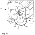
- the fourth running surface 45 is arranged such that upon engagement of the second running cam 41 in the fourth running surface 45, a locking of the dispensing drum 28 in the dispensing position he follows. Such a situation is described below Fig. 21 shown.
- Fig. 21 shows the drive mechanism according to Fig. 20 wherein the dispensing drum is rotated to a dispensing position.
- the opening 29 is further oriented to an externally accessible side, which was previously blocked in the receiving position by the output drum 28.
- a product not shown in the output drum 28 can now be removed from the outside through the opening 29 from the output drum 28.
- the first running cam 37 has a circular shape concentric with the translation element 33, wherein a first recess 46 is provided only in the area of the first pin 35, which serves for the passage of the first contact section 34 of the partitioning element 26.
- the second barrel cam 41 is formed analogously to the first barrel cam 37, and with respect to the first barrel cam 37 an angular offset also arranged concentrically on the transmission element 33 and provided with a second recess 47, as in Fig. 20 shown. Accordingly, the second pin 40 is arranged with an equal angular offset from the first pin 35. It is therefore always an engagement of the transmission element 33 in the second contact portion 42 of the output drum 28 is present, either by means of the second run cam 42 or by means of the second pin 40th
- the drive device 31 may comprise a drive mechanism 32 only on one or both sides of the dispenser 24.
- the entire drive mechanism 32 as well as the first and second contact portions 34, 42 may accordingly be provided equally on an opposite lateral side of the dispenser 24.
- Fig. 22 shows a perspective sectional view of an output device 24th
- the dispensing drum 28 has a front panel 48 which, in the receiving position, constitutes a first side wall of the dispensing drum 28 and closes a region in which the opening 29 is located in the dispensing position. Furthermore, the dispensing drum 28 has a rear wall 49 which, in the receiving position, represents a second side wall of the dispensing drum 28. The rear wall 49 is rounded.
- the output drum 28 has a bottom 25 arranged opposite the opening 29 between the front panel 48 and the rear wall 49.
- the output drum 28 has a lateral wall 50, in which the rotation axis 27 is embedded.
- the partitioning element 26 is in the in Fig. 4 shown opened position behind the rear wall 49 adjusted.
- the partitioning element 26 has a rounded sheet-metal section 51, the rounding of the sheet-metal section 51 corresponding to the rounding of the rear wall 49.
- the respective curves of the rear wall 49 and the sheet metal portion 51 are formed with the rotation axis 27 as the center.
- Fig. 23 shows a perspective sectional view of the dispenser according to Fig. 22 with the partitioning element 26 adjusted to a closed position. The dispensing drum 28 is still in the receiving position.
- the receiving area 30 is accordingly blocked inaccessible by the partition element 26. Furthermore, in the closed position, the partitioning element 26 complements the shape of the dispensing drum 28 in the receiving position such that the opening 29 is completely closed. Thus, a fully closed position of the dispenser 24 is taken.
- a loading compartment 2 for example, as in Fig. 4 shown by means of a roller 18, roll on the rounded sheet metal portion 51 of the closed partition element 24, which then serves as below the loading compartment 2 arranged base 19.
- the Output device 24 thus also functions as a goods lock, which at no time allows a simultaneous opening to the receiving area 30 and to the outside. Instead, the dispensing drum only opens to the outside by rotation in the dispensing position when the partition member 26 is fully closed and locked. After the output, the partitioning element 26 opens only by adjusting in the open position when the output drum 28 is fully closed, that is rotated and locked in the receiving position.
- the dispensing drum 28 When the dispensing drum 28 is closed in the receiving position and the partitioning element 26 is open, the dispensing drum 28 can not be opened manually. When the dispensing drum 28 is open in the dispensing position, the partitioning element 26 can not be opened manually.
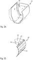
- Fig. 24 shows a sectional perspective view of an output drum 28.
- the output drum 28 has a configuration as described with respect to Fig. 22 is described.
- Fig. 25 shows a perspective sectional view of a partition element 5.
- a lateral portion 52 of the partition member 26 can be seen. Furthermore, a first contact section 34 of the partition element 26 can be seen, in which the rotation axis 27 is embedded. The lateral portion 52 connects the rounded sheet metal portion 51 with the first contact portion 34.
- a motorized tilting of the loading compartment is conceivable.
- a self-locking gear for example a worm gear, be provided to hold the loading tray 2 in the horizontal position or to block.
- an input or operating device coupled to the control device can furthermore be provided.
Landscapes
- Physics & Mathematics (AREA)
- General Physics & Mathematics (AREA)
- Control Of Vending Devices And Auxiliary Devices For Vending Devices (AREA)
- Vending Machines For Individual Products (AREA)
Abstract
Description
- Die vorliegende Erfindung betrifft eine Liftvorrichtung für einen Warenautomaten, einen Warenautomaten mit einer solchen Liftvorrichtung sowie ein Verfahren zum Betreiben eines solchen Warenautomaten.
- Bei Warenautomaten, insbesondere bei Verkaufsautomaten, besteht oftmals die Anforderung, die darin angebotenen Waren vor einer Ausgabe zu präsentieren. Meist ist dazu eine durchsichtige Scheibe an der Front des Warenautomaten vorgesehen, hinter welcher die Waren sichtbar, in der Regel stehend, in Warenmagazinen angeordnet sind. Derartige Warenmagazine weisen meist eine Mehrzahl nebeneinander angeordneter Warenfächer auf. Ferner ist meist eine Vielzahl von Warenmagazinen vorgesehen, die übereinander angeordnet sind. Die Waren können beispielsweise durch einen in den Warenfächern vorgesehenen Spiraltrieb, einen linearen Schieber oder einen anderen Vorschubmechanismus aus den einzelnen Warenfächern ausgegeben werden.
- Bei früheren Warenautomaten sind die Waren nach der Ausgabe aus einem Warenfach frei in eine Ausgabevorrichtung gefallen. Hierbei können die Waren jedoch beschädigt oder verschlechtert werden. Daher wird zum kontrollierteren Transferieren der Waren von einem Warenfach zu einer Ausgabevorrichtung ein Transfersystem, ein sogenannter Lift, eingesetzt.
- Ein solches Transfersystem ist beispielsweise in der
EP 2 232 451 B1 beschrieben. Dieses weist zwei Konfigurationen einer Transfereinrichtung auf, wobei die Transfereinrichtung in einer ersten Konfiguration eine konkave Form aufweist, in welcher aus einem Warenfach ausgegebenen Produkte gehalten werden, und in einer zweiten Konfiguration die Waren frei aus der Transfereinrichtung heraus in eine Ausgabe fallen. - Auch wenn die Fallhöhe mit einem solchen Transfersystem reduziert ist, fallen die Waren damit nach wie vor aus einer gewissen Höhe aus der Transfereinrichtung in die Ausgabe. Des Weiteren ist ein aufwendiger Mechanismus mit einer Vielzahl von beweglichen Teilen wie Hebeln, Gelenken und Führungen sowie einer Federvorspannung notwendig, um die verschiedenen Konfigurationen der Transfereinrichtung zu realisieren.
- Vor diesem Hintergrund liegt der vorliegenden Erfindung die Aufgabe zugrunde, eine verbesserte Liftvorrichtung anzugeben.
- Erfindungsgemäß wird diese Aufgabe durch eine Liftvorrichtung mit den Merkmalen des Patentanspruchs 1 und/oder durch einen Warenautomaten mit den Merkmalen des Patentanspruchs 8 und/oder durch ein Verfahren mit den Merkmalen des Patentanspruches 13 gelöst.
- Demgemäß ist vorgesehen:
- Eine Liftvorrichtung für einen Warenautomaten, mit einem Ladefach zur Aufnahme von aus einem Warenmagazin ausgegebenen Waren, mit zumindest einem Laufschlitten zum Verfahren des Ladefachs in einer Höhenrichtung, wobei sich das Ladefach in einer geraden Stellung vom Laufschlitten abstehend entlang einer Querrichtung erstreckt, um aus in einem Warenmagazin nebeneinander angeordneten Warenfächern Waren aufnehmen zu können, wobei das Ladefach um eine in einer Tiefenrichtung orientierte Kippachse in eine verkippte Stellung verkippbar am Laufschlitten gelagert ist.
- Ein Warenautomat, insbesondere Verkaufsautomat, mit einer Vielzahl von übereinander angeordneten Warenmagazinen, wobei jedes Warenmagazin eine Mehrzahl von in einer Querrichtung nebeneinander angeordneten Warenfächern zur Aufnahme von Waren aufweist, mit einer erfindungsgemäßen Liftvorrichtung, mit einer Ausgabevorrichtung zur Ausgabe einer Ware aus dem Automaten, wobei die Liftvorrichtung vorgesehen ist, aus den Warenfächern ausgegebene Waren aufzunehmen, zur Ausgabevorrichtung zu transportieren und durch Verkippen des Ladefachs in die Ausgabevorrichtung zu übergeben.
- Ein Verfahren zum Betreiben eines Warenautomaten, insbesondere eines erfindungsgemäßen Warenautomaten, mit den Schritten: Ausgabe einer Ware aus einem Warenfach eines Warenmagazins, welches eine Vielzahl von in einer Querrichtung nebeneinander angeordneten Warenfächern aufweist, in ein Ladefach einer Liftvorrichtung; Verfahren des Ladefachs in Höhenrichtung zu einer Ausgabevorrichtung; Übergabe der Ware aus dem Ladefach an die Ausgabevorrichtung durch Verkippen des Ladefachs um eine in einer Tiefenrichtung orientierte Kippachse.
- Die der vorliegenden Erfindung zugrunde liegende Idee besteht darin, ein an einem Laufschlitten gelagertes Ladefach um eine in Tiefenrichtung verlaufende Kippachse verkippbar vorzusehen. Damit wird ein sanftes Ablegen von Waren in einer Ausgabevorrichtung ermöglicht. Gleichzeitig erlaubt dies eine Realisierung mit einer sehr einfachen Mechanik bzw. Kinematik, die insbesondere ohne zusätzliche Antriebe, Umlenkhebel, Zusatzgelenke oder dergleichen auskommt.
- Der Laufschlitten ist bevorzugt seitlich an der Liftvorrichtung angeordnet und läuft bevorzugt in einer in Höhenrichtung verlaufenden Führung. Das Ladefach erstreckt sich vom Laufschlitten in der geraden Stellung entlang einer Querrichtung, insbesondere parallel zu einem Warenmagazin.
- Bevorzugt erstreckt sich das Ladefach über die gesamte Breite des Warenmagazins. Alternativ kann das Ladefach auch schmaler und/oder zusätzlich in Querrichtung verfahrbar vorgesehen sein.
- Es können auch zwei parallel laufende Laufschlitten, insbesondere an beiden Seiten der Liftvorrichtung, vorgesehen sein.
- Unter einem Laufschlitten ist ein in der Führung laufender Schlitten zu verstehen, der entweder extern, beispielsweise über einen Riemen- oder Kettentrieb, oder intern, beispielsweise mittels eines integrierten Motors, angetrieben wird. Auch ein Linearantrieb des Laufschlittens in der Führung ist denkbar.
- Unter einer Höhenrichtung ist bevorzugt eine vertikale Richtung zu verstehen.
- Unter einer Querrichtung bzw. Breitenrichtung des Ladefachs ist bevorzugt eine horizontale Richtung zu verstehen, die insbesondere der Breitenrichtung eines Warenmagazins entspricht, und entlang welcher die Warenfächer nebeneinander angeordnet sind. In einem Warenautomaten entspricht dies in der Regel gleichzeitig der horizontalen Richtung in der Ebene der Front bzw. der durchsichtigen Frontscheibe. Somit verlaufen die Front des Warenautomaten, das Warenmagazin und das Ladefach in der horizontalen Querrichtung bevorzugt jeweils parallel zueinander.
- Unter einer geraden Stellung des Ladefachs ist dementsprechend bevorzugt eine horizontale Stellung des Ladefachs zu verstehen.
- Unter einer Tiefenrichtung ist bevorzugt eine ebenfalls horizontale Richtung zu verstehen, die innerhalb einer horizontalen Ebene quer zur Querrichtung (bzw. Breitenrichtung) verläuft.
- Die Höhenrichtung, die Querrichtung und die Tiefenrichtung stehen somit bevorzugt jeweils senkrecht zueinander und spannen somit ein orthogonales Richtungssystem auf. Allerdings ist die Erfindung darauf nicht beschränkt, sondern es sind auch Abweichungen von einer Orthogonalität der Richtungen mit umfasst. Insbesondere sind Fertigungstoleranzen und Abweichungen im Rahmen eines Einstellbereichs oder im Rahmen einer fachmännischen Auslegung der Höhen-, Quer- und Tiefenrichtung mit umfasst. Denkbar sind dabei leichte Richtungsabweichungen im Bereich von bis zu maximal 45°, bevorzugt im Bereich kleiner als 10°.
- Somit sind unter den Quer- und Tiefenrichtungen auch Richtungen zu verstehen, die ggfs. leicht schräg zu einer horizontalen Ebene verlaufen und/oder in einem Winkel zueinander verlaufen, der leicht von einem rechten Winkel abweicht. Selbiges gilt analog für eine gerade Stellung des Ladefachs.
- Unter der Höhenrichtung sind dementsprechend auch Richtungen zu verstehen, die in einer vertikalen Ebene leicht schräg zur Vertikalen verlaufen.
- Unter einer Kippachse ist eine Achse zu verstehen, um welche das Ladefach bei Bedarf kippbar ist. Insbesondere kann das Warenfach frei, das heißt schwerkraftbeschleunigt, kippbar sein. Dafür ist die in Tiefenrichtung verlaufende Kippachse besonders vorteilhaft, denn die Gestalt des Ladefachs ist aufgrund der Breite des Warenmagazins in der Regel entlang der horizontalen Querrichtung länglich ausgebildet und lediglich seitlich am Laufschlitten gelagert. Für ein schwerkraftbeschleunigtes Verkippen steht somit vorteilhaft ein maximaler Hebelarm zur Verfügung, sodass das Verkippen funktionssicher ablaufen kann.
- Allerdings ist die Erfindung nicht auf ein schwerkraftbeschleunigtes Verkippen beschränkt. Vielmehr kann zusätzlich auch eine die Kippachse in der geraden Stellung des Ladefachs vorspannende Vorspannfeder vorgesehen sein, um das Verkippen in die verkippte Stellung zu unterstützen. Ferner ist auch ein motorisch betriebenes Verkippen denkbar. Beispielsweise kann dazu ein Kippmotor vorgesehen sein, der insbesondere in den Laufschlitten oder in das Ladefach integriert ist.
- Vorteilhafte Ausgestaltungen und Weiterbildungen ergeben sich aus den weiteren Unteransprüchen sowie aus der Beschreibung unter Bezugnahme auf die Figuren der Zeichnung.
- Gemäß einer Ausführungsform ist an dem Laufschlitten und optional oder zusätzlich an einem weiteren Laufschlitten ein Rastmechanismus zum lösbaren Einrasten des Ladefachs in der geraden Stellung vorgesehen. Somit wird das Ladefach in der geraden Stellung, die bevorzugt eine horizontale Stellung darstellt, durch den Rastmechanismus lösbar gehalten bzw. fixiert. Zum Verkippen des Ladefachs wird der Rastmechanismus einfach gelöst bzw. freigegeben. Somit wird vorteilhaft eine besonders einfach aufgebaute und damit auch einfach herzustellende Kipp- und Rastmechanik geschaffen. Der Rastmechanismus kann an demselben Laufschlitten wie die Kippachse oder an einem zweiten oder weiteren, parallel laufenden Laufschlitten vorgesehen sein.
- Gemäß einer Ausführungsform ist in einer vorbestimmten Stellung des Laufschlittens, insbesondere in einer in Höhenrichtung tiefsten Stellung des Laufschlittens, ein Auslösemittel zum Lösen des Rastmechanismus vorgesehen. Der Rastmechanismus ist dabei vorgesehen und ausgebildet, beim Lösen durch das Auslösemittel entriegelt zu werden, sodass das Ladefach um die in Tiefenrichtung orientierte Kippachse verkippbar ist. Vorteilhaft wird das Ladefach somit an einer vorbestimmten Position verkippt, so dass es die Ware beispielsweise an eine Ausgabevorrichtung eines Warenautomaten übergibt. Insbesondere ist das Ladefach frei verkippbar, d.h. es verkippt alleine aufgrund seiner Schwerkraft aus der horizontalen Stellung in die verkippte Stellung. Das Auslösemittel kann beispielsweise mechanisch als den Rastmechanismus entriegelnder Stift oder dergleichen ausgebildet sein. Alternativ kann das Auslösemittel auch als ein elektrischer Kontakt ausgebildet sein, der eine elektrische oder elektrisch angetriebene Entriegelung des Rastmechanismus bewirkt. Ferner ist auch ein berührungsloses Auslösemittel denkbar, beispielsweise in Form eines Hall-Sensors in Verbindung mit einem Steuergerät, welches einen Aktor am Rastmechanismus auf Eingabe eines vorbestimmten Signals des Hall-Sensors zur Freigabe des Rastmechanismus entsprechend ansteuert.
- Gemäß einer vorteilhaften Ausführungsform ist die Kippachse im Bereich des Bodens des Ladefachs angeordnet. Vorteilhaft ist somit gewährleistet, dass beim Aufsetzen des Ladefachs auf einem horizontalen Untergrund das Ladefach eine gerade bzw. horizontale Stellung einnimmt. Ferner ist somit sichergestellt, dass sich die Breite des Ladefachs im gelösten Zustand des Rastmechanismus durch ein Verkippen nicht vergrößert. Damit ist gewährleistet, dass sich das Ladefach beim Verkippen nicht mit anderen Komponenten verkantet oder blockiert. Insbesondere wenn das Ladefach in einen in eine Ausgabevorrichtung eingefahrenen Zustand verkippt wird ist somit sichergestellt, dass das Ladefach und die Ausgabevorrichtung sich nicht gegenseitig behindern, da das Ladefach beim Verkippen nicht nach außen ausschwenkt.
- Gemäß einer Ausführungsform weist die Kippachse einen Anschlag auf. Alternativ oder zusätzlich kann auch das Ladefach einen Anschlag aufweisen. Der Anschlag begrenzt das Verkippen des Ladefachs auf einen maximalen Verkippwinkel relativ zur Querrichtung. Bei Erreichen des maximalen Verkippwinkels ist die verkippte Stellung des Ladefachs erreicht. Der maximale Verkippwinkel ist kleiner als 90°, damit eine Rückführung des Ladefachs in eine gerade bzw. horizontale Stellung durch Aufsetzen auf einem im Wesentlichen in Querrichtung bzw. horizontal verlaufenden Untergrund möglich ist. Bei einem Winkel größer als 90° würde das Ladefach beim Aufsetzen in die falsche Richtung gekippt werden. Bei Winkeln nahe 90° sind vergleichsweise hohe Kräfte notwendig, um das Ladefach aus der verkippten Stellung eine horizontale Stellung zu bewegen. Daher betragen sinnvolle maximale Verkippwinkel maximal 85°. Damit eine zuverlässige Übergabe der Ware erfolgt, sollte der Verkippwinkel nicht kleiner als 50° sein. Ein guter Kompromiss aus Rückstellbarkeit und Zuverlässigkeit der Übergabe wird im Bereich von 60° bis 70° erzielt. Somit beträgt ein sinnvoller Bereich des maximalen Verkippwinkels zwischen 50° und 85°, vorzugsweise zwischen 60° und 70°.
- Bei einer vorteilhaften Ausführungsform ist der Rastmechanismus durch Rückführen des Ladefachs in die gerade Stellung verrastbar vorgesehen. Zum Verrasten des Rastmechanismus, d.h. zum Fixieren des Ladefachs in der geraden, insbesondere horizontalen, Stellung, braucht das Ladefach somit lediglich in die gerade Stellung gebracht werden. Das Rückführen des Ladefachs in die gerade Stellung wird bevorzugt durch Aufsetzen des verkippten Ladefachs auf einem Untergrund, insbesondere einem horizontalen Untergrund, und Verfahren des Laufschlittens in Richtung des Untergrunds so lange, bis die gerade Stellung des Ladefachs wieder erreicht ist, bewirkt. Dabei gleitet das Ladefach an dem Untergrund ab. Am Boden des Ladefachs können dazu im Bereich einer in der verkippten Stellung den tiefsten Punkt des Ladefachs bildenden Kante Gleitmittel, beispielsweise eine Rolle oder eine reibungsreduzierte gekrümmte Fläche, vorgesehen sein. Vorteilhaft ist somit zum Rückführen des Ladefachs in die gerade Stellung keine zusätzliche Rückführvorrichtung nötig, was die Teileanzahl reduziert und die Komplexität der Liftvorrichtung vermindert. Somit können vorteilhaft Kosten für die Herstellung, Montage und Wartung einer zusätzlichen Rückführvorrichtung eingespart werden. Alternativ oder zusätzlich kann auch ein Motor zum Verkippen und/oder zum Rückführen des Ladefachs vorgesehen sein.
- Gemäß einer Ausführungsform ist an den querseitigen Enden des Ladefachs jeweils ein Laufschlitten vorgesehen. Das Ladefach ist entweder einteilig ausgebildet oder in eine erste und eine zweite Hälfte geteilt ausgebildet. Im Falle einer geteilten Ausbildung ist die erste Hälfte an einem ersten Laufschlitten um eine in Tiefenrichtung orientierte erste Kippachse verkippbar gelagert. Ferner ist die zweite Hälfte an einem zweiten Laufschlitten um eine in Tiefenrichtung orientierte zweite Kippachse verkippbar gelagert. Der erste und zweite Laufschlitten sind dabei bevorzugt an zwei parallelen, insbesondere vertikalen, Führungen vorgesehen, die jeweils an einem querseitigen Ende des Ladefachs in Höhenrichtung verlaufen und bevorzugt als Laufschienen ausgebildet sind. Alternativ zu einer Ausführungsform mit zwei Hälften kann das Ladefach auch einteilig ausgebildet sein. In diesem Fall ist das Ladefach lediglich an einem querseitigen Ende an einem Laufschlitten, der in einer in Höhenrichtung verlaufenden Führung vorgesehen ist, verkippbar gelagert. In diesem Fall kann bevorzugt ein zweiter in einer parallelen zweiten Führung laufender Lauschlitten vorgesehen, an welchem der Rastmechanismus vorgesehen ist. Alternativ kann auch nur ein einzelner Laufschlitten vorgesehen sein, an dem zusätzlich zur Kippachse auch der Rastmechanismus vorgesehen ist.
- Bei einer Ausführungsform eines Warenautomaten ist das Ladefach der Liftvorrichtung zum Übergeben der Ware in die Ausgabevorrichtung hineinfahrbar vorgesehen. Dazu ist die Ausgabevorrichtung in einem den Warenmagazinen zugewandten Bereich, insbesondere an einer Oberseite der Ausgabevorrichtung, offen bzw. öffenbar ausgebildet, sodass das Ladefach durch die Öffnung hindurch in die Ausgabevorrichtung einfahren kann. Dies hat den besonderen Vorteil, dass die Ware nicht über die Höhe der Ausgabevorrichtung in dieselbe hineinfällt, sondern innerhalb der Ausgabevorrichtung sanft abgelegt werden kann. Insbesondere fährt das Ladefach zum Übergeben der Ware bis an den Boden der Ausgabevorrichtung.
- Gemäß einer vorteilhaften Ausführungsform sind die Auslösemittel derart angeordnet, dass der Rastmechanismus erst nach dem Einfahren des Ladefachs in die Ausgabevorrichtung gelöst wird. Bevorzugt lösen die Auslösemittel den Rastmechanismus erst dann, wenn das Ladefach an einem Boden der Ausgabevorrichtung angelangt ist. Die Übergabe der Ware an die Ausgabevorrichtung erfolgt durch Verkippen des Ladefachs beim Herausfahren des Ladefachs aus der Ausgabevorrichtung. Während der Übergabe der Ware fällt dieselbe daher nicht aus dem verkippten bzw. geöffnete Ladefach, sondern bleibt, abgesehen von einer Resthöhe zwischen dem Boden des Ladefachs und dem Boden der Ausgabevorrichtung, im Wesentlichen auf gleicher Höhe während das Ladefach verkippt. Beim Verkippen des Ladefachs entsteht ein Spalt bzw. eine Öffnung, durch welche die Ware in die Ausgabevorrichtung gleiten kann, ohne dass sie sich dabei wesentlich in Höhenrichtung bewegt. Vorteilhaft wird somit ein unerwünschtes Herunterfallen der Ware wirksam vermieden. Somit ist gewährleistet, dass die Ware nicht beschädigt, verschlechtert oder unerwünscht stark geschüttelt wird. Denkbar aber nicht notwendig ist hierzu ein komplettes Aufsetzen des Bodens des Ladefachs auf dem Boden der Ausgabevorrichtung bevor dem Lösen des Rastmechanismus, um eine etwaige dazwischenliegende Resthöhe zu minimieren.
- Gemäß einer Ausführungsform weist die Ausgabevorrichtung eine bewegliche Sicherungsvorrichtung auf. Diese ist insbesondere als ein verfahrbares Abschottungselement, ein so genannter Shutter, ausgebildet. Die Sicherungsvorrichtung ist ausgelegt und vorgesehen, in einem geschlossenen Zustand den Bereich der Warenmagazine bei der Ausgabe einer Ware aus der Ausgabevorrichtung gegen unbefugten Zugriff, insbesondere gegen einen Warendiebstahl und/oder gegen Vandalismus, zu sichern. Sie ist ferner vorgesehen in einem geöffneten Zustand ein Einfahren des Ladefachs in die Ausgabevorrichtung zu erlauben. Insbesondere ist die Sicherungsvorrichtung dazu an einer in der Ausgabevorrichtung vorgesehenen Öffnung beweglich, bevorzugt rotierbar, vorgesehen, sodass sie die Öffnung im geschlossenen Zustand verschließt und im geöffneten Zustand zum Einfahren des Ladefachs freigibt.
- Gemäß einer vorteilhaften Ausführungsform eines Warenautomaten ist die Sicherungsvorrichtung an ihrer den Warenmagazinen zugewandten Seite in der geschlossenen Stellung als Untergrund zum Aufsetzen des verkippten Ladefachs und Rückführen des Ladefachs in die gerade Stellung vorgesehen und ausgelegt. Dazu weist die Sicherungsvorrichtung im geschlossenen Zustand eine in Querrichtung, insbesondere horizontal, verlaufende Fläche oder Gleitbahn auf, auf welcher das verkippte Ladefach abgleiten kann. Die Rückführung erfolgt entsprechend durch Verfahren des Laufschlittens in Richtung der Sicherungsvorrichtung, d.h. in Höhenrichtung nach unten, wobei das Ladefach an der Sicherungsvorrichtung abgleitet und so in die gerade, insbesondere horizontale, Stellung geführt wird. Bei Erreichen der geraden Stellung wird der Rastmechanismus automatisch verrastet.
- Bei einer bevorzugten Ausführungsform eines Verfahrens zum Betreiben eines Warenautomaten fährt das Ladefach für die Übergabe der Ware in die Ausgabevorrichtung hinein. Insbesondere fährt das Ladefach soweit hinein, dass es an einem Boden der Ausgabevorrichtung aufsetzt. Anschließend wird das Ladefach beim Herausfahren aus der Ausgabevorrichtung verkippt. Bevorzugt verkippt das Ladefach frei, d.h. durch seine Schwerkraft. Während dem Verkippen beim Herausfahren des Ladefachs aus der Ausgabevorrichtung wird die Ware an die Ausgabevorrichtung übergeben, indem sich beim Verkippen ein Spalt bzw. eine Öffnung bildet, durch welche die Ware dann in die Ausgabevorrichtung gleitet. Vorteilhaft wird die Ware beim Verkippen des Ladefachs in Höhenrichtung nicht wesentlich verlagert, sodass die Ware beim Übergeben nicht aus dem Ladefach fällt, sondern sanft in der Ausgabevorrichtung abgelegt wird.
- Gemäß einer Ausführungsform eines Verfahrens zum Betreiben eines Warenautomaten wird zum Verkippen des Ladefachs ein Rastmechanismus gelöst. Der Rastmechanismus ist durch Rückführen des Ladefachs aus einer verkippten Stellung in eine gerade Stellung wieder verrastbar vorgesehen. Dies geschieht insbesondere durch Aufsetzen des verkippten Ladefachs auf einem Untergrund. Die gerade Stellung entspricht dabei insbesondere einer horizontalen Stellung des Ladefachs. Bevorzugt dient als Untergrund ein Abschottungselement der Ausgabevorrichtung. Das Abschottungselement wird nach dem Herausfahren des Ladefachs aus der Ausgabevorrichtung in einen geschlossenen Zustand bewegt. Anschließend wird das Ladefach auf dem geschlossenen Abschottungselement zum Rückführen in die gerade Stellung aufgesetzt.
- Die obigen Ausgestaltungen und Weiterbildungen lassen sich, sofern sinnvoll, beliebig miteinander kombinieren. Insbesondere sind sämtliche Merkmale des Warenautomaten auch auf das Verfahren zum Betreiben des Warenautomaten übertragbar und umgekehrt sämtliche Merkmale des Verfahrens zum Betreiben des Warenautomaten auf den Warenautomaten selbst bzw. dessen Liftvorrichtung übertragbar. Weitere mögliche Ausgestaltungen, Weiterbildungen und Implementierungen der Erfindung umfassen auch nicht explizit genannte Kombinationen von zuvor oder im Folgenden bezüglich der Ausführungsbeispiele beschriebenen Merkmale der Erfindung. Insbesondere wird dabei der Fachmann auch Einzelaspekte als Verbesserungen oder Ergänzungen zu der jeweiligen Grundform der vorliegenden Erfindung hinzufügen.
- Die vorliegende Erfindung wird nachfolgend anhand der in den schematischen Figuren der Zeichnung angegebenen Ausführungsbeispiele näher erläutert. Es zeigen dabei:
- Fig. 1
- eine Liftvorrichtung gemäß einem ersten Ausführungsbeispiel;
- Fig. 2
- die Liftvorrichtung gemäß
Fig. 1 mit verkipptem Ladefach; - Fig. 3
- eine Detailansicht eines Ladefachs einer Liftvorrichtung gemäß
Fig. 1 und2 in einer geraden Stellung; - Fig. 4
- eine Detailansicht des Ladefachs gemäß
Fig. 3 in einer verkippten Stellung; - Fig. 5
- eine Liftvorrichtung gemäß einem zweiten Ausführungsbeispiel;
- Fig. 6
- die Liftvorrichtung gemäß
Fig. 5 mit verkipptem Ladefach; - Fig. 7
- eine schematische Darstellung eines Warenautomaten in einer Ausgangsstellung;
- Fig. 8
- eine Seitenansicht eines Abschnitts des Warenautomaten gemäß
Fig. 7 ; - Fig. 9
- den Warenautomat gemäß
Fig. 7 in einer Abhohlposition der Liftvorrichtung; - Fig. 10
- den Warenautomat gemäß
Fig. 9 mit einer in das Ladefach der Liftvorrichtung ausgegebenen Ware; - Fig. 11
- den Warenautomat gemäß
Fig. 10 in einer Übergabeposition der Liftvorrichtung; - Fig. 12
- den Warenautomat gemäß
Fig. 11 in der Übergabeposition mit gelöstem Rastmechanismus; - Fig. 13
- den Warenautomat gemäß
Fig. 12 beim Herausfahren der Liftvorrichtung aus der Ausgabevorrichtung zur Übergabe der Ware; - Fig. 14
- den Warenautomat gemäß
Fig. 13 in einer verkippten, aus der Ausgabevorrichtung herausgefahren Position der Liftvorrichtung; - Fig. 15
- den Warenautomat gemäß
Fig. 14 in einer Ausgabeposition der Ausgabevorrichtung mit geschlossenem Abschottungselement; - Fig. 16
- den Warenautomat gemäß
Fig. 15 nach dem Rückführen des Ladefachs aus der verkippten Stellung in eine gerade Stellung; - Fig. 17
- den Warenautomat gemäß
Fig. 16 mit geöffnetem Abschottungselement der Ausgabevorrichtung; - Fig. 18
- den Warenautomat gemäß
Fig. 17 mit in die Ausgangsstellung zurückgefahrener Liftvorrichtung; - Fig. 19A
- eine perspektivische Ansicht einer Ausgabevorrichtung;
- Fig. 19B
- die Ausgabevorrichtung gemäß
Fig. 19A mit in eine geschlossene Stellung verstelltem Abschottungselement; - Fig. 20
- eine Detailansicht eines Antriebsmechanismus mit eingezeichneten verdeckten Kanten;
- Fig. 21
- den Antriebsmechanismus gemäß
Fig. 20 , wobei die Ausgabetrommel in eine Ausgabestellung rotiert ist; - Fig. 22
- eine perspektivische Schnittansicht einer Ausgabevorrichtung;
- Fig. 23
- eine perspektivische Schnittansicht der Ausgabevorrichtung gemäß
Fig. 22 mit in eine geschlossene Stellung verstelltem Abschottungselement; - Fig. 24
- eine perspektivische Schnittansicht einer Ausgabetrommel;
- Fig. 25
- eine perspektivische Schnittansicht eines Abschottungselements.
- Die beiliegenden Figuren der Zeichnung sollen ein weiteres Verständnis der Ausführungsformen der Erfindung vermitteln. Sie veranschaulichen Ausführungsformen und dienen im Zusammenhang mit der Beschreibung der Erklärung von Prinzipien und Konzepten der Erfindung. Andere Ausführungsformen und viele der genannten Vorteile ergeben sich im Hinblick auf die Zeichnungen. Die Elemente der Zeichnungen sind nicht notwendigerweise maßstabsgetreu zueinander gezeigt.
- In den Figuren der Zeichnung sind gleiche, funktionsgleiche und gleich wirkende Elemente, Merkmale und Komponenten - sofern nichts anderes ausgeführt ist - jeweils mit denselben Bezugszeichen versehen.
-
Fig. 1 zeigt eine Liftvorrichtung 1 gemäß einem ersten Ausführungsbeispiel. Es handelt sich dabei um eine Liftvorrichtung 1 mit einem einteiligen Ladefach 2. - Die Liftvorrichtung 1 weist ferner zwei gegenüberliegende Laufschlitten 3 auf, an welchen das Ladefach 2 gelagert ist.
- Die Laufschlitten 3 laufen jeweils in einer als vertikale Laufschiene ausgebildeten Führung 13, welche jeweils an einer Querseite der Liftvorrichtung 1 angeordnet sind. Somit ist das Ladefach in einer vertikalen Höhenrichtung 4 verstellbar.
- In der dargestellten geraden bzw. horizontalen Ausrichtung des Ladefachs 2 erstreckt sich dieses in horizontaler Querrichtung 5 zwischen den beiden Laufschlitten 3. Das Ladefach 2 ist an einem Laufschlitten 3 über eine in einer vertikalen Tiefenrichtung verlaufende Kippachse 6 gelagert und an einem weiteren gegenüberliegenden Laufschlitten 3 über einen lösbaren Rastmechanismus 7 in der geraden Stellung verrastet gehalten.
- Angetrieben sind die Laufschlitten 3 gleichläufig, beispielsweise jeweils über einen nicht näher dargestellten motorbetriebenen Seilzug. Alternativ ist auch ein Antrieb über einen jeweils in den Laufschlitten 3 integrierten Motor oder über einen jeweils in die Führungen 13 und die Laufschlitten 3 integrierten Linearantrieb möglich.
-
Fig. 2 zeigt die Liftvorrichtung 1 gemäßFig. 1 mit verkipptem Ladefach 2. Die dargestellte verkippte Stellung des Ladefachs 2 ist einnehmbar, wenn der Rastmechanismus 7 gelöst wird, sodass ein am Ladefach 2 vorgesehener Rastriegel 14 vom Rastmechanismus 7 freigegeben wird und das Ladefach 2 frei um die Kippachse 6 verkippen kann. Der Rastmechanismus 7 ist dabei derart ausgelegt, dass ein Rückführen des Ladefachs 2 in die gerade Stellung ein Verrasten des Rastmechanismus 7 bewirkt. - Die Kippachse 6 ist mittels eines im Bereich eines Bodens 9 des Ladefachs 2 vorgesehenen Scharniers 15 realisiert, welches ein freies Verkippen des Ladefachs 2 gegenüber dem Laufschlitten 3 zulässt, wenn der Rastmechanismus 7 gelöst ist.
-
Fig. 3 zeigt eine Detailansicht eines Ladefachs 2 einer Liftvorrichtung 1 gemäßFig. 1 und2 in einer geraden Stellung. Insbesondere ist darin der Rastmechanismus 7 gut erkennbar, welcher den besagten Rastriegel 14 sowie einen federvorgespannten Rastvorsprung 16 umfasst. Wird das Ladefach 2 entlang der vertikalen Höhenrichtung 4 verfahren, so trifft der Rastmechanismus 7 an einer vorbestimmten Stelle, an welcher das Ladefach 2 verkippt werden soll, insbesondere einer tiefsten Position bzw. Übergabeposition des Ladefachs auf ein Auslösemittel 8. Das Auslösemittel ist hier schematisch als ein Auslösestift 8 dargestellt. Der Auslösestift 8 ist derart angeordnet, dass er bei Verfahren des Ladefachs 2 in eine entsprechende Position den Rastvorsprung 16 entgegen seiner Federvorspannung eindrückt, ohne dabei den Rastriegel 14 zu blockieren. Somit wird der Rastriegel 14, wenn der Auslösestift 8 den Rastvorsprung 16 eindrückt, freigegeben, sodass das Ladefach 2 um die Kippachse 6 frei verkippbar ist. -
Fig. 4 zeigt eine Detailansicht des Ladefachs 2 gemäßFig. 3 in einer verkippten Stellung. Das Ladefach 2 ist beim Verkippen in einer Führungsnut 17 geführt. Die Führungsnut 17 weist einen Anschlag 10 auf, welcher den maximalen Verkippwinkel um die Kippachse 6 auf 70° begrenzt bzw. definiert. - Des Weiteren ist eine im Bereich des Rastriegels 14 angeordnete Rolle 18 vorgesehen, welche dazu ausgebildet ist, auf einem unterhalb des Ladefachs 2 angeordneten, hier lediglich schematisch eingezeichneten Untergrund 19 abzurollen, wenn die beiden Laufschlitten 3 in der vertikalen Höhenrichtung 4 nach unten verfahren. Durch das Abrollen der Rolle 18 auf dem Untergrund 19 wird das Ladefach 2 bei weiterem Verfahren der Laufschlitten 3 in Höhenrichtung 4 nach unten um die Kippachse 6 zurück in die gerade bzw. horizontale Stellung gekippt. Bei Erreichen der geraden Stellung rastet der Rastriegel 14 am Rastvorsprung 16 ein, sodass der Rastmechanismus 7 wieder verrastet ist.
-
Fig. 5 zeigt eine Liftvorrichtung 1 gemäß einem zweiten Ausführungsbeispiel. Im Unterschied zum ersten Ausführungsbeispiel gemäß denFiguren 1 bis 4 weist diese Liftvorrichtung 1 ein geteiltes Ladefach 2 mit einer ersten Hälfte 11 und einer zweiten Hälfte 12 auf. Die erste Hälfte 11 ist an einem in einer ersten als Laufschiene ausgebildeten Führung 13a laufenden ersten Laufschlitten 3a über eine erste in horizontaler Tiefenrichtung verlaufende Kippachse 6a verkippbar gelagert. Die zweite Hälfte 12 ist an einem in einer zweiten als Laufschiene ausgebildeten Führung 13b laufenden zweiten Laufschlitten 3b über eine zweite in horizontaler Tiefenrichtung verlaufende Kippachse 6b verkippbar gelagert. - Jeder der Laufschlitten 3a, 3b weist einen Rastmechanismus 7a bzw. 7b auf, welcher hier zur besseren Übersichtlichkeit nicht im Detail gezeigt ist. Es handelt sich dabei um einen funktionell zum Rastmechanismus 7 des ersten Ausführungsbeispiels gemäß
Fig. 1 bis 4 im Wesentlichen analogen Rastmechanismus, mit dem Unterschied, dass die jeweilige Kippachse 6a bzw. 6b und der jeweilige Rastmechanismus 7a bzw. 7b hier jeweils an demselben Laufschlitten 3a bzw. 3b vorgesehen sind. Dementsprechend sind auch ebenfalls nicht dargestellte Auslösemittel 8a, 8b an beiden Seiten der Liftvorrichtung 1 an einer vorbestimmten Position, an welcher die beiden Hälften 11, 12 des Ladefachs 2 verkippt werden sollen, vorgesehen. - In der dargestellten geraden Stellung der beiden Hälften 11, 12 stehen diese jeweils in horizontaler Querrichtung 5 von den jeweiligen Laufschlitten 3a, 3b ab.
-
Fig. 6 zeigt die Liftvorrichtung 1 gemäßFig. 5 mit verkipptem Ladefach 2. die beiden Hälften 11, 12 des Ladefachs 2 sind dabei um die ihnen jeweils zugeordnete Kippachse 6a bzw. 6b in eine verkippte Stellung verkippt. Auch bei diesem zweiten Ausführungsbeispiel mit geteiltem Ladefach 2 ist analog zum ersten Ausführungsbeispiel ein hier nicht näher dargestellter Anschlag 10 für jede der Hälften 11, 12 des Ladefachs 2 vorgesehen, um den Verkippwinkel auf 70° zu begrenzen. - Des Weiteren sind die beiden Hälften 11, 12 des Ladefachs 2 in analoger Weise wie das Ladefach 2 gemäß dem ersten Ausführungsbeispiel in die gerade Stellung zurückverstellbar, indem sie an einem hier nicht dargestellten Untergrund unterhalb des Ladefachs während einem Verstellen der Laufschlitten 3a, 3b nach unten in vertikaler Höhenrichtung 4 abgleiten. Hierzu können ebenfalls hier nicht dargestellte Rollen oder alternativ Gleitflächen oder dergleichen im Bereich des Bodens 9a, 9b der beiden Hälften 11, 12 vorgesehen sein.
-
Fig. 7 zeigt eine schematische Darstellung eines Warenautomaten 20 in einer Ausgangsstellung. Der Warenautomat 20 ist hier zur besseren Übersichtlichkeit schematisch ohne ein Gehäuse und ohne eine Frontblende bzw. Frontscheibe dargestellt. Des Weiteren sind die Führungen bzw. Laufschienen 13a, 13b der Liftvorrichtung 1 ausgeblendet. - Der Warenautomat 20 weist eine Vielzahl von Warenmagazinen 21 auf, welche in vertikaler Höhenrichtung 4 übereinander angeordnet sind. Dargestellt sind rein beispielhaft lediglich zwei übereinander angeordnete Warenmagazine 21, jedoch kann eine beliebige an die Größe des Warenautomaten 20 und an die Höhe der Waren 23 angepasste Vielzahl von Warenmagazinen 21 übereinander angeordnet sein.
- Der Warenautomat 20 weist eine Liftvorrichtung 1 auf. Diese ist hier beispielhaft gemäß dem zweiten Ausführungsbeispiel der
Figuren 5 und6 mit einem zweiteiligen Ladefach dargestellt. Ebenso kann es sich jedoch auch um eine Liftvorrichtung 1 gemäß dem ersten Ausführungsbeispiel derFiguren 1 bis 4 mit einteiligem Ladefach handeln. Die nachfolgende Funktionsbeschreibung bzw. das nachfolgend beschriebene Verfahren zum Betreiben des Warenautomaten ist somit analog auf einen Warenautomaten mit einer Liftvorrichtung 1 gemäß dem ersten Ausführungsbeispiel übertragbar. - Der Warenautomat 20 weist ferner eine Ausgabevorrichtung 24 auf. In dem dargestellten Ausführungsbeispiel handelt es sich dabei um eine sogenannte Ausgabetrommel.
- Die übereinander angeordneten Warenmagazine 21 weisen jeweils eine Mehrzahl von nebeneinander angeordneten Warenfächern 22 auf. In dem dargestellten Ausführungsbeispiel handelt es sich beispielhaft um jeweils acht nebeneinander angeordneten Warenfächer 22 innerhalb eines Warenmagazins 21. Jedoch kann eine beliebige an die Größe des Warenautomaten 20 und an die Breite der Waren 23 angepasste Mehrzahl von Warenfächern 22 nebeneinander vorgesehen sein.
- Jedes Warenfach 22 ist mit einer Beförderungsvorrichtung zum Ausgeben einer Ware 23 in das Ladefach 2 versehen. Dabei kann es sich beispielsweise um eine Förderspirale, um einen Spiraltrieb oder um einen linear beweglichen Schieber handeln. Des Weiteren ist an einem vorderen Ende eines jeden Warenfachs 22 eine Rückhaltefeder vorgesehen, welche ein unbeabsichtigtes Ausgeben einer Ware 23 verhindert.
- In
Fig. 7 ist als sich in einem Warenfach 22 befindliche Ware 23 beispielhaft eine Getränkeflasche dargestellt. Bei der Ware 23 könnte es sich jedoch ebenso um eine beliebige andere Ware handeln, beispielsweise eine Getränkedose, ein umverpacktes oder in einer Tüte verpacktes Nahrungs- oder Genussmittel, oder auch Non-Food-Waren wie Zigarettenschachteln, Fahrradschläuche, oder andere Produkte. - In der in
Fig. 7 dargestellten Ausgangsposition der Liftvorrichtung 1 ist diese bzw. deren Ladefach 2 in die Ausgabevorrichtung 24 eingefahren. Somit ist von außerhalb des Automaten der Blick durch eine hier nicht gezeigte Frontscheibe des Warenautomaten 20 auf die in den Warenmagazinen 21 gelagerten Waren 23 frei. - Wird ausgehend von dieser Ausgangsstellung eine Ware 23 angefordert, beispielsweise aufgrund einer Benutzereingabe von außen, so beginnt das Verfahren zum Betreiben des Warenautomaten 20. Insbesondere ist eine nicht dargestellte Steuervorrichtung vorgesehen, die den Warenautomaten, insbesondere die Antriebe des Warenautomaten, im Betrieb, insbesondere auf eine Benutzereingabe hin, entsprechend steuert.
-
Fig. 8 zeigt eine Seitenansicht eines Abschnitts des Warenautomaten 20 gemäßFig. 7 . Der gezeigte Abschnitt weist ein Warenmagazin 21, die Liftvorrichtung 1 sowie die Ausgabevorrichtung 24 auf. Die Liftvorrichtung 1 bzw. deren Ladefach 2 ist dabei analog zur inFig. 7 gezeigten Stellung in die Ausgabevorrichtung 24 eingefahren. - An der Ausgabevorrichtung 24 ist eine Sicherungsvorrichtung 26, ein sogenannter Shutter, in Form eines verfahrbaren Abschottungselements 26 vorgesehen, welches in dem dargestellten geöffneten Zustand ein Einfahren des Ladefachs 2 in die Ausgabevorrichtung 24 zulässt. Wie mit den in
Fig. 8 eingezeichneten Pfeilen angedeutet, ist ein geschlossener Zustand des Abschottungselements 26 einnehmbar, wenn das Ladefach 2 aus der Ausgabevorrichtung 24 herausgefahren ist. Der geschlossene Zustand wird dann durch eine motorisch betriebene Rotation des Abschottungselements 26 um eine Rotationsachse 27 erreicht. In dem nicht dargestellten geschlossenen Zustand versperrt das Abschottungselement 26 die Öffnung der Ausgabevorrichtung 24 zu den Warenmagazinen 21. Somit ist der Bereich der Warenmagazine 21 von der Ausgabevorrichtung 24 aus unzugänglich. Auf den Mechanismus des Abschottungselements 26 wird in Bezug auf dieFiguren 19 bis 26 näher eingegangen. -
Fig. 9 zeigt den Warenautomat 20 gemäßFig. 7 in einer Abhohlposition der Liftvorrichtung 1. In dieser Position ist das Ladefach 2 aus der Ausgabevorrichtung 24 in vertikaler Höhenrichtung 4 nach oben herausgefahren und auf Höhe eines Warenmagazins 21 angeordnet. Die Liftvorrichtung 1 ist in dieser Position bereit, eine in einem Warenfach 22 des Warenmagazins 21 gelagerte Ware 23 aufzunehmen, wenn diese aus dem Warenfach 22 ausgegeben wird. -
Fig. 10 zeigt den Warenautomat 20 gemäßFig. 9 mit einer in das Ladefach 2 der Liftvorrichtung 1 ausgegebenen Ware 23. Ist die Ware 23, wie dargestellt, in dem Ladefach 2 aufgenommen, kann die Liftvorrichtung 1 in vertikaler Höhenrichtung 4 nach unten zur Ausgabevorrichtung 24 verfahren werden, um die Ware 23 an die Ausgabevorrichtung 24 zu übergeben. -
Fig. 11 zeigt den Warenautomat 20 gemäßFig. 10 in einer Übergabeposition der Liftvorrichtung 1. in dieser Übergabeposition ist die Liftvorrichtung 1 bzw. deren Ladefach 2 in vertikaler Höhenrichtung 4 nach unten bis in die Ausgabevorrichtung 24 verfahren. In dieser Übergabeposition kann die Ware 23 an die Ausgabevorrichtung 24 übergeben werden. Dazu wird an beiden Hälften 11, 12 des Ladefachs 2 der jeweils zugehörige Rastmechanismus 7a, 7b, welcher hier zur besseren Übersichtlichkeit nicht im Detail dargestellt ist, gelöst. -
Fig. 12 zeigt den Warenautomat 20 gemäßFig. 11 in der Übergabeposition mit gelöstem Rastmechanismus 7a, 7b. Bei gelöstem Rastmechanismus 7a, 7b sind die beiden Hälften 11, 12 des Ladefachs 2 um ihre jeweilige Kippachse 6a, 6b frei verkippbar. Somit setzen die Hälften 11, 12 des Ladefachs 2 an einem Boden 25 der Ausgabevorrichtung 24 auf. Durch ein Herausfahren des Ladefachs 2 aus der Ausgabevorrichtung 24 in vertikaler Höhenrichtung 4 nach oben aus der Ausgabevorrichtung 24 verkippen die Hälften 11, 12 des Ladefachs 2 weiter um ihre jeweilige Kippachse 6a, 6b, wodurch die Ware auf sanfte Weise an die Ausgabevorrichtung 24 übergebbar ist. -
Fig. 13 zeigt den Warenautomat 20 gemäßFig. 12 beim Herausfahren der Liftvorrichtung 1 aus der Ausgabevorrichtung 24 zur Übergabe der Ware 23. Beim Herausfahren des Ladefachs 2 aus der Ausgabevorrichtung 24 verkippen die Hälften 11, 12 weiter um ihre jeweilige Kippachse 6a, 6b. Dabei gleitet die Ware 23 an den Hälften 11, 12 des Ladefachs 2 ab, sodass die Ware 23 sanft, d.h. ohne zu Fallen, auf dem Boden 25 der Ausgabevorrichtung 24 abgelegt wird. -
Fig. 14 zeigt den Warenautomat 20 gemäßFig. 13 in einer verkippten, aus der Ausgabevorrichtung 24 herausgefahren Position der Liftvorrichtung 1. In dieser Position ist die Liftvorrichtung 1 vollständig aus der Ausgabevorrichtung 24 herausgefahren. D.h. die Hälften 11, 12 des Ladefachs 2 sind auch in der verkippten Stellung samt ihrer tiefsten Kante vollständig aus der Ausgabevorrichtung 24 herausgefahren, sodass die Ausgabevorrichtung 24 nun mittels des Abschottungselements 26 verschlossen werden kann. -
Fig. 15 zeigt den Warenautomat 20 gemäßFig. 14 in einer Ausgabeposition der Ausgabevorrichtung mit geschlossenem Abschottungselement 26. - In dieser Stellung können die Hälften 11 und 12 des Ladefachs 2 wieder zurück ihre gerade bzw. horizontale Stellung gebracht werden, indem die Laufschlitten 3a und 3b der Liftvorrichtung 1 in vertikaler Höhenrichtung 4 nach unten in Richtung des Abschottungselements 26 gefahren werden. Dabei setzen die verkippten Hälften 11, 12 des Ladefachs 2 auf dem Abschottungselement 26 auf. Das Abschottungselement 26 dient somit als Untergrund, auf dem das Ladefach 2 bzw. dessen beiden Hälften 11 und 12 abgleiten und so um ihre jeweilige Kippachse 6a, 6b zurück in die gerade Stellung verkippt werden, wie mit den eingezeichneten Pfeilen angedeutet.
-
Fig. 16 zeigt den Warenautomat 20 gemäßFig. 15 nach dem Rückführen des Ladefachs 2 aus der verkippten Stellung in eine gerade Stellung. Die Ware 23 ist bereits aus der Ausgabevorrichtung 24 entnommen, sodass diese nun leer ist. - Das Ladefach 2 ist soweit in Richtung des Abschottungselements 26 verfahren, dass es mit seinem gesamten Boden 9 bzw. dass die beiden Hälften 11, 12 des Ladefachs 2 mit ihren jeweiligen Böden 9a, 9b vollständig auf dem Abschottungselement 26 aufliegen. In dieser geraden Stellung verrastet der jeweilige den Hälften 11 und 12 des Ladefachs 2 zugeordnete Rastmechanismus 7a, 7b. Das Ladefach 2 ist nun wieder in der geraden Stellung lösbar verrastet.
-
Fig. 17 zeigt den Warenautomat 20 gemäßFig. 16 mit geöffnetem Abschottungselement 26 der Ausgabevorrichtung 24. Das Abschottungselement 26 ist durch Rotation um die Rotationsachse 28 zurück in den inFig. 8 gezeigten geöffneten Zustand verfahren. Die Liftvorrichtung 1 kann nun zurück in die Ausgangsstellung verfahren werden, in dem die Laufschlitten 3a, 3b in vertikaler Höhenrichtung 4 nach unten verfahren werden. -
Fig. 18 zeigt den Warenautomat 20 gemäßFig. 17 mit in die Ausgangsstellung zurückgefahrener Liftvorrichtung 1. Die eingenommene Ausgangsstellung entspricht der inFig. 7 dargestellten ursprünglichen Ausgangsstellung. Das Ladefach ist dazu durch Verfahren der Laufschlitten 3a, 3b in vertikaler Höhenrichtung 4 nach unten in die Ausgabevorrichtung 24 hineingefahren. - Das Verfahren zum Betreiben des Warenautomaten 20 hat nun einen vollständigen Zyklus durchlaufen. Bei Anforderung eines weiteren wahren Produktes 23 beginnt das Verfahren zum Betreiben des Warenautomaten dementsprechend von neuem.
-
Fig. 19A zeigt eine perspektivische Ansicht einer Ausgabevorrichtung 24. Die Ausgabevorrichtung 24 weist eine rotierbare Ausgabetrommel 28 sowie ein verstellbares Abschottungselement 26 auf. Ferner ist eine Antriebsvorrichtung 31 zum Verstellen des Abschottungselements 26 und zum Rotieren der Ausgabetrommel 28 vorgesehen. - Die Ausgabetrommel 28 kann zwischen einer Aufnahmestellung und einer Ausgabestellung rotiert werden. Dargestellt ist die Ausgabetrommel 28 in
Fig. 19A der Aufnahmestellung. Die Ausgabetrommel 28 ist in der Aufnahmestellung zur Aufnahme einer nicht dargestellten Ware und in der Ausgabestellung zur Ausgabe der nicht dargestellten Ware ausgebildet. - Zur Aufnahme und Ausgabe einer Ware ist eine Öffnung 29 an der Ausgabetrommel 28 vorgesehen. In der dargestellten Aufnahmestellung befindet sich die Öffnung 29 an einem Aufnahmebereich 30, in welchem eine Ware aufgenommen werden kann. Somit kann eine Ware aufgenommen werden, die aus dem Ladefach 2 der Liftvorrichtung in die Ausgabevorrichtung 24 übergeben wird.
- Das Abschottungselement 26 ist in einer geöffneten Stellung zur Freigabe des Aufnahmebereichs 30 und in einer geschlossenen Stellung zum unzugänglichen Versperren des Aufnahmebereichs 30 vorgesehen und ausgebildet. Dargestellt ist das Abschottungselement 26 in
Fig. 19A in der geöffneten Stellung. Das Abschottungselement 26 ist durch die Antriebsvorrichtung 31 in die geschlossene Stellung verstellbar, worauf in Bezug aufFig. 19B näher eingegangen wird. - Zur Ausgabe der Ware ist die Ausgabetrommel 28 durch die Antriebsvorrichtung 31 in die Ausgabestellung rotierbar. Dies ist jedoch nur möglich, wenn zuvor das Abschottungselement 26 in die geschlossene Stellung verstellt ist.
-
Fig. 19B zeigt die Ausgabevorrichtung gemäßFig. 19A mit in eine geschlossene Stellung verstelltem Abschottungselement 26. Der Aufnahmebereich 30 ist in der dieser geschlossenen Stellung des Abschottungselements 26 unzugänglich versperrt. - Sowohl das Abschottungselement 26 als auch die Ausgabetrommel 28 sind an einer gemeinsamen Rotationsachse 27 unabhängig voneinander drehbar gelagert. Dementsprechend kann das Abschottungselement 26 mittels der Antriebsvorrichtung 31 durch Rotieren um die Rotationsachse 27 verstellt werden.
- Die Antriebsvorrichtung 31 umfasst einen Antriebsmechanismus 32, der ein Übersetzungselement 33 aufweist. Das Übersetzungselement 33 ist über eine am Umfang des Übersetzungselements 33 vorgesehenen Verzahnung mit einem nicht dargestellten Antrieb antreibbar. Beispielsweise kämmt dazu ein Ritzel des Antriebs mit der Verzahnung des Übersetzungselements 33.
- Die Ausgabetrommel 28 ist nicht manuell zu öffnen, sie wird über eine mechanische Steuerkurve durch den selben Antrieb wie das Abschottungselement 26 über das Übersetzungselement 33 motorisch angetrieben. Um ein Einklemmen zu verhindern ist eine Drehmomentbegrenzung und dadurch eine Begrenzung der Schließkraft vorgesehen. Beispielsweise ist eine Drehmomentbegrenzung in Form einer Rutschkupplung oder in Form einer sensorischen Erfassung des Drehmoments und einer entsprechenden Steuerung, welche bei einem vorbestimmten maximalen Drehmoment abschaltet, realisiert. Ferner kann eine Steuerung derart realisiert sein, dass für den Fall, dass der Antrieb beim Rotieren der Ausgabetrommel oder beim Verstellen des Abschottungselements innerhalb einer bestimmten Zeit nicht seine vorgesehene Endposition erreicht, angenommen wird, dass in der Klappe etwas eingeklemmt wurde und der Antrieb daher zurückgefahren wird.
- Das Übersetzungselement 33 ist dazu ausgebildet, mit einem am Abschottungselement 26 vorgesehenen ersten Kontaktabschnitt 34 zu interagieren.
- Dazu weist das Übersetzungselement 33 einen ersten Zapfen 35 auf. Der erste Kontaktabschnitt 34 des Abschottungselements 26 weist dazu eine erste Führung 36 auf, in welche der erste Zapfen 35 je nach Stellung des Übersetzungselements 33 zeitweise eingreifen kann. Mittels Eingreifen des ersten Zapfens 35 in die erste Führung 36 ist das Abschottungselement 26 zwischen der geschlossenen und der geöffneten Stellung verstellbar. Im dargestellten Ausführungsbeispiel führt in einer geöffneten Stellung des Abschottungselements 26 gemäß
Fig. 19A eine Rotation des Übersetzungselements 33 im Uhrzeigersinn zu einem Verstellen des Abschottungselements 26 durch eine Rotation um die Rotationsachse 27 entgegen dem Uhrzeigersinn. - Des Weiteren weist das Übersetzungselement 33 einen ersten Laufnocken 37 auf. Der erste Kontaktabschnitt 34 des Abschottungselements 26 weist eine dazu korrespondierende ausgebildete erste Lauffläche 38 sowie eine ebenfalls dazu korrespondierend ausgebildeten zweite Lauffläche 39 auf. Mittels eines Eingriffs des ersten Laufnockens 37 in die erste oder zweite Lauffläche 38, 39 ist jeweils ein Formschluss herstellbar, welcher das Abschottungselement 26 arretiert.
- Die erste Lauffläche 38 ist derart angeordnet, dass bei einem Eingriff des ersten Laufnockens 37 in die erste Lauffläche 38 eine Arretierung des Abschottungselements 26 in der geschlossenen Stellung erfolgt. Eine solche Situation ist
Fig. 19B dargestellt. - Die zweite Lauffläche 39 ist derart angeordnet, dass bei einem Eingriff des ersten Laufnockens 37 in die zweite Lauffläche 39 eine Arretierung des Abschottungselements 26 in der geöffneten Stellung erfolgt. Eine solche Situation in
Fig. 19A dargestellt. - Der erste Zapfen 35 und der erste Laufnocken 37 sind jeweils an einer gleichen, in
Fig. 19B dargestellten Seite des Übersetzungselements 33 angeordnet. Zusätzlich zum ersten Zapfen 35 und zum ersten Laufnocken 37 weist das Übersetzungselement 33 an der gegenüberliegenden Seite einen zweiten Zapfen 40 sowie einen zweiten Laufnocken 41 auf. Des Weiteren weist die Ausgabetrommel 28 einen durch das Abschottungselement 26 verdeckten zweiten Kontaktabschnitt 42 auf. -
Fig. 20 zeigt eine Detailansicht eines Antriebsmechanismus 32 mit eingezeichneten verdeckten Kanten. Im Folgenden werden die zugehörigen verdeckten Abschnitte bzw. Teile beschrieben. - Das Übersetzungselement 33 ist ebenfalls dazu ausgebildet, mit dem an der Ausgabetrommel 28 vorgesehenen zweiten Kontaktabschnitt 42 zu interagieren und weist dazu den zweiten Zapfen 40 auf. Der zweite Kontaktabschnitt 42 der Ausgabetrommel 28 weist dazu eine zweite Führung 43 auf, in welche der zweite Zapfen 40 je nach Stellung des Übersetzungselements 33 zeitweise eingreifen kann. Mittels Eingreifen des zweiten Zapfens 40 in die zweite Führung 43 ist die Ausgabetrommel 28 zwischen der Aufnahmestellung und der Ausgabestellung rotierbar.
- Im dargestellten Ausführungsbeispiel führt in der Aufnahmestellung der Ausgabetrommel 28 gemäß
Fig. 20 eine weitere Rotation des Übersetzungselements 33 im Uhrzeigersinn zu einer Rotation der Ausgabetrommel 28 um die Rotationsachse 27 entgegen dem Uhrzeigersinn. - Des Weiteren weist das Übersetzungselement 8 einen zweiten Laufnocken 41 auf. Der zweite Kontaktabschnitt 42 der Ausgabetrommel 28 weist ferner eine dazu korrespondierend ausgebildete dritte Lauffläche 44 sowie eine ebenfalls dazu korrespondierend ausgebildete vierte Lauffläche 45 auf. Mittels eines Eingriffs des zweiten Laufnockens 41 in die dritte oder vierte Lauffläche 44, 45 ist jeweils ein Formschluss herstellbar, welcher die Ausgabetrommel 28 arretiert.
- Die dritte Lauffläche 44 ist derart angeordnet, dass bei einem Eingriff des zweiten Laufnockens 41 in die dritte Lauffläche 44 eine Arretierung der Ausgabetrommel 28 in der Aufnahmestellung erfolgt. Eine solche Situation ist in
Fig. 20 dargestellt. - Die vierte Lauffläche 45 ist derart angeordnet, dass bei einem Eingriff des zweiten Laufnockens 41 in die vierte Lauffläche 45 eine Arretierung der Ausgabetrommel 28 in der Ausgabestellung erfolgt. Eine solche Situation ist in der nachfolgend beschriebenen
Fig. 21 dargestellt. -
Fig. 21 zeigt den Antriebsmechanismus gemäßFig. 20 , wobei die Ausgabetrommel in eine Ausgabestellung rotiert ist. - In dieser Situation ist durch einen Eingriff des hier verdeckten zweiten Laufnockens 41 in die hier verdeckte vierte Lauffläche 45 eine Arretierung der Ausgabetrommel 28 in der Ausgabestellung erfolgt.
- In der dargestellten Ausgabestellung der Ausgabetrommel 28 ist ferner die Öffnung 29 zu einer von außen zugänglichen Seite orientiert, welche zuvor in der Aufnahmestellung durch die Ausgabetrommel 28 versperrt war. Somit kann eine sich in der Ausgabetrommel 28 befindliche nicht dargestellte Ware nun von außen durch die Öffnung 29 aus der Ausgabetrommel 28 entnommen werden.
- Gleichzeitig liegt nach wie vor eine Arretierung des Abschottungselements 26 durch Eingriff des ersten Laufnockens 37 in die erste Lauffläche 38 vor. Der erste Laufnocken 37 weist dazu eine zum Übersetzungselement 33 konzentrische Kreisform auf, wobei lediglich im Bereich des ersten Zapfens 35 eine erste Ausnehmung 46 vorgesehen ist, welche zur Durchführung des ersten Kontaktabschnitts 34 des Abschottungselements 26 dient. Somit ist stets ein Eingriff des Übersetzungselements 33 in den ersten Kontaktabschnitt 34 des Abschottungselements 26 vorhanden, entweder mittels des ersten Laufnockens 37 oder mittels des ersten Zapfens 35.
- Der zweite Laufnocken 41 ist analog zum ersten Laufnocken 37 geformt, und mit relativ zum ersten Laufnocken 37 einem Winkelversatz ebenfalls konzentrisch am Übersetzungselement 33 angeordnet und mit einer zweiten Ausnehmung 47 versehen, wie in
Fig. 20 dargestellt. Dementsprechend ist auch der zweite Zapfen 40 mit einem gleichen Winkelversatz zum ersten Zapfen 35 angeordnet. Es ist daher auch stets ein Eingriff des Übersetzungselements 33 in den zweiten Kontaktabschnitt 42 der Ausgabetrommel 28 vorhanden, entweder mittels des zweiten Laufnockens 42 oder mittels des zweiten Zapfens 40. - Die Antriebsvorrichtung 31 kann nur an einer oder auch an beiden Seiten der Ausgabevorrichtung 24 einen Antriebsmechanismus 32 umfassen. Der gesamte Antriebsmechanismus 32 sowie der erste und zweite Kontaktabschnitt 34, 42 können dementsprechend an einer gegenüberliegenden lateralen Seite der Ausgabevorrichtung 24 gleichermaßen vorgesehen sein.
-
Fig. 22 zeigt eine perspektivische Schnittansicht einer Ausgabevorrichtung 24. - Die Ausgabetrommel 28 weist eine Frontblende 48 auf, welche in der Aufnahmestellung eine erste Seitenwand der Ausgabetrommel 28 darstellt und einen Bereich verschließt, in dem sich in der Ausgabestellung die Öffnung 29 befindet. Des Weiteren weist die Ausgabetrommel 28 eine Rückwand 49 auf, welche in der Aufnahmestellung eine zweite Seitenwand der Ausgabetrommel 28 darstellt. Die Rückwand 49 ist gerundet ausgebildet.
- Des Weiteren weist die Ausgabetrommel 28 zwischen der Frontblende 48 und der Rückwand 49 einen gegenüber der Öffnung 29 angeordneten Boden 25 auf. Darüber hinaus weist die Ausgabetrommel 28 eine laterale Wand 50 auf, in welcher die Rotationsachse 27 eingelassen ist.
- Das Abschottungselement 26 ist in der in
Fig. 4 dargestellten geöffneten Stellung hinter die Rückwand 49 verstellt. Das Abschottungselement 26 weist dazu einen gerundeten Blechabschnitt 51 auf, wobei die Rundung des Blechabschnitts 51 zur Rundung der Rückwand 49 korrespondiert. Insbesondere sind die jeweiligen Rundungen der Rückwand 49 und des Blechabschnitts 51 mit der Rotationsachse 27 als Zentrum gebildet. -
Fig. 23 zeigt eine perspektivische Schnittansicht der Ausgabevorrichtung gemäßFig. 22 mit in eine geschlossene Stellung verstelltem Abschottungselement 26. Die Ausgabetrommel 28 befindet sich dabei nach wie vor in der Aufnahmestellung. - Der Aufnahmebereich 30 ist dementsprechend durch das Abschottungselement 26 unzugänglich versperrt. Des Weiteren ergänzt das Abschottungselement 26 in der geschlossenen Stellung die Form der Ausgabetrommel 28 in der Aufnahmestellung derart, dass die Öffnung 29 vollständig verschlossen ist. Somit ist eine vollständig geschlossene Stellung der Ausgabevorrichtung 24 eingenommen.
- In dieser geschlossenen Stellung des Abschottungselements kann ein Ladefach 2, beispielsweise wie in
Fig. 4 gezeigt mittels einer Rolle 18, auf dem gerundeten Blechabschnitt 51 des geschlossenen Abschottungselements 24 abrollen, welches dann als unterhalb des Ladefachs 2 angeordneter Untergrund 19 dient. - Dreht sich die Ausgabetrommel 28 nun in die Ausgabestellung, so entsteht eine Zugänglichkeit von außen in dem Bereich, welcher zuvor durch die Frontblende 48 verschlossen ist. Die Ausgabevorrichtung 24 fungiert somit auch als Warenschleuse, welche zu keinem Zeitpunkt eine gleichzeitige Öffnung zum Aufnahmebereich 30 und nach außen zulässt. Stattdessen öffnet die Ausgabetrommel erst dann nach außen durch Rotation in die Ausgabestellung, wenn das Abschottungselement 26 vollständig geschlossen und arretiert ist. Nach der Ausgabe öffnet das Abschottungselement 26 erst durch Verstellen in die geöffnete Stellung, wenn die Ausgabetrommel 28 vollständig geschlossen, d. h. in die Aufnahmeposition rotiert und arretiert ist.
- Bei geschlossener Ausgabetrommel 28 in der Aufnahmestellung und geöffnetem Abschottungselement 26 lässt sich die Ausgabetrommel 28 nicht manuell öffnen. Bei geöffneter Ausgabetrommel 28 in der Ausgabeposition lässt sich das Abschottungselement 26 nicht manuell öffnen.
-
Fig. 24 zeigt eine perspektivische Schnittansicht einer Ausgabetrommel 28. die Ausgabetrommel 28 weist eine Ausbildung auf, wie sie in Bezug aufFig. 22 beschrieben ist. -
Fig. 25 zeigt eine perspektivische Schnittansicht eines Abschottungselements 5. - Zusätzlich zu der in Bezug auf
Fig. 22 bereits beschriebenen Ausbildung des gerundeten Blechabschnitts 51 ist hier zusätzlich ein lateraler Abschnitt 52 des Abschottungselements 26 erkennbar. Des Weiteren ist ein erster Kontaktabschnitt 34 des Abschottungselements 26 ersichtlich, in welchen die Rotationsachse 27 eingelassen ist. Der laterale Abschnitt 52 verbindet den gerundeten Blechabschnitt 51 mit dem ersten Kontaktabschnitt 34. - Obwohl die vorliegende Erfindung anhand bevorzugter Ausführungsbeispiele vorstehend vollständig beschrieben wurde, ist sie darauf nicht beschränkt, sondern auf vielfältige Art und Weise modifizierbar.
- So ist beispielsweise in einem Warenautomaten anstatt einer Liftvorrichtung mit einem geteilten Ladefach ebenso eine Liftvorrichtung mit einem einteiligen Ladefach entsprechend einsetzbar.
- Ferner ist anstatt einem freien Verkippen des Ladefachs und/oder anstatt dem Vorsehen eines Rastmechanismus ein motorisches Verkippen des Ladefachs denkbar. In diesem Fall kann optional oder zusätzlich zum Rastmechanismus an einem Verkippmotor ein selbsthemmendes Getriebe, beispielsweise ein Schneckenradgetriebe, vorgesehen sein, um das Ladefach 2 in der horizontalen Stellung zu halten bzw. zu blockieren.
- Für das Anfordern einer Ware durch einen Benutzer kann ferner eine mit der Steuervorrichtung gekoppelte Eingabe- bzw. Bedienvorrichtung vorgesehen sein.
-
- 1
- Liftvorrichtung
- 2
- Ladefach
- 3, 3a, 3b
- Laufschlitten
- 4
- Höhenrichtung
- 5
- Querrichtung
- 6, 6a, 6b
- Kippachse
- 7, 7a, 7b
- Rastmechanismus
- 8
- Auslösemittel bzw. Auslösestift
- 9, 9a, 9b
- Boden
- 10
- Anschlag
- 11
- erste Hälfte
- 12
- zweite Hälfte
- 13, 13a, 13b
- Führung bzw. Laufschiene
- 14
- Rastriegel
- 15
- Scharnier
- 16
- Rastvorsprung
- 17
- Führungsnut
- 18
- Rolle
- 19
- Untergrund
- 20
- Warenautomat
- 21
- Warenmagazin
- 22
- Warenfach
- 23
- Ware
- 24
- Ausgabevorrichtung
- 25
- Boden
- 26
- Sicherungsvorrichtung bzw. Abschottungselement
- 27
- Rotationsachse
- 28
- Ausgabetrommel
- 29
- Öffnung
- 30
- Aufnahmebereich
- 31
- Antriebsvorrichtung
- 32
- Antriebsmechanismus
- 33
- Übersetzungselement
- 34
- erster Kontaktabschnitt
- 35
- erster Zapfen
- 36
- erste Führung
- 37
- erster Laufnocken
- 38
- erste Lauffläche
- 39
- zweite Lauffläche
- 40
- zweiter Zapfen
- 41
- zweite Führung
- 42
- zweiter Kontaktabschnitt
- 43
- zweite Führung
- 44
- dritte Lauffläche
- 45
- vierte Lauffläche
- 46
- erste Ausnehmung
- 47
- zweite Ausnehmung
- 48
- Frontblende
- 49
- Rückwand
- 50
- laterale Wand
- 51
- gerundeter Blechabschnitt
- 52
- lateraler Abschnitt
Claims (15)
- Liftvorrichtung (1) für einen Warenautomaten,
mit einem Ladefach (2) zur Aufnahme von aus einem Warenmagazin ausgegebenen Waren,
mit zumindest einem Laufschlitten (3; 3a, 3b) zum Verfahren des Ladefachs (2) in einer Höhenrichtung (4), wobei sich das Ladefach (2) in einer geraden Stellung vom Laufschlitten (3; 3a, 3b) abstehend entlang einer Querrichtung (5) erstreckt, um aus in einem Warenmagazin nebeneinander angeordneten Warenfächern Waren aufnehmen zu können, wobei das Ladefach (2) um eine in einer Tiefenrichtung orientierte Kippachse (6; 6a, 6b) in eine verkippte Stellung verkippbar am Laufschlitten (3; 3a, 3b) gelagert ist. - Liftvorrichtung nach Anspruch 1
dadurch gekennzeichnet,
dass an dem Laufschlitten (3; 3a, 3b) und/oder an einem weiteren Laufschlitten (3; 3a, 3b) ein Rastmechanismus (7; 7a, 7b) zum lösbaren Einrasten des Ladefachs (2) in der geraden Stellung vorgesehen ist. - Liftvorrichtung nach Anspruch 2,
dadurch gekennzeichnet,
dass in einer vorbestimmten Stellung des Laufschlittens (3; 3a, 3b), insbesondere einer in Höhenrichtung tiefsten Stellung des Laufschlittens (3; 3a, 3b), ein Auslösemittel (8) zum Lösen des Rastmechanismus (7; 7a, 7b) vorgesehen ist, wobei der Rastmechanismus (7; 7a, 7b) vorgesehen und ausgebildet ist, beim Lösen durch das Auslösemittel (8) entriegelt zu werden, sodass das Ladefach (2) um die in der Tiefenrichtung orientierte Kippachse (6; 6a, 6b) in die verkippte Stellung verkippbar ist, insbesondere frei verkippbar ist. - Liftvorrichtung nach einem der vorangehenden Ansprüche,
dadurch gekennzeichnet,
dass die Kippachse (6; 6a, 6b) im Bereich eines Bodens (9) des Ladefachs (2) angeordnet ist. - Liftvorrichtung nach einem der vorangehenden Ansprüche,
dadurch gekennzeichnet,
dass die Kippachse (6; 6a, 6b) und/oder das Ladefach (2) einen Anschlag (10) aufweist, der das Verkippen des Ladefachs (2) auf einen maximalen Verkippwinkel relativ zur Querrichtung (5) begrenzt, wobei der maximale Verkippwinkel kleiner als 90° ist, insbesondere in einem Bereich zwischen 50° und 85°, vorzugsweise zwischen 60° und 70° liegt. - Liftvorrichtung nach einem der Ansprüche 2 bis 5
dadurch gekennzeichnet,
dass der Rastmechanismus (7; 7a, 7b) durch Rückführen des Ladefachs (2) in die gerade Stellung verrastbar vorgesehen ist, insbesondere bei Aufsetzen des verkippten Ladefachs (2) auf einem Untergrund (19) und Verfahren des Laufschlittens (3; 3a, 3b) in Richtung des Untergrunds (19) bis die gerade Stellung des Ladefachs (2) wieder erreicht ist. - Liftvorrichtung nach einem der vorstehenden Ansprüche,
dadurch gekennzeichnet,
dass an den querseitigen Enden des Ladefachs (2) jeweils ein Laufschlitten (3; 3a, 3b) vorgesehen ist, wobei das Ladefach (2) einteilig ausgebildet ist oder in eine erste und eine zweite Hälfte (11, 12) geteilt ausgebildet und mit der ersten Hälfte (11) an einem ersten Laufschlitten (3a) um eine in Tiefenrichtung orientierte Kippachse (6a) verkippbar gelagert ist und mit der zweiten Hälfte (12) an einem zweiten Laufschlitten (3b) um eine in Tiefenrichtung orientierte zweite Kippachse (6b) verkippbar gelagert ist. - Warenautomat (2), insbesondere Verkaufsautomat,
mit einer Vielzahl von übereinander angeordneten Warenmagazinen (21), wobei jedes Warenmagazin (21) eine Mehrzahl von in einer Querrichtung (5) nebeneinander angeordneten Warenfächern (22) zur Aufnahme von Waren (23) aufweist,
mit einer Liftvorrichtung (1) gemäß einem der vorstehenden Ansprüche,
mit einer Ausgabevorrichtung (24) zur Ausgabe einer Ware aus dem Warenautomaten (20), wobei die Liftvorrichtung (1) vorgesehen ist, aus den Warenfächern (21) ausgegebene Waren (23) aufzunehmen, zur Ausgabevorrichtung (24) zu transportieren und durch Verkippen des Ladefachs (2) in die Ausgabevorrichtung (24) zu übergeben. - Warenautomat nach Anspruch 8,
dadurch gekennzeichnet,
dass das Ladefach (2) der Liftvorrichtung (1) zum Übergeben der Ware (23) in die Ausgabevorrichtung (24) hineinfahrbar vorgesehen ist. - Warenautomat nach Anspruch 9,
dadurch gekennzeichnet,
dass die Auslösemittel (8) derart angeordnet sind, dass der Rastmechanismus (7; 7a, 7b) erst nach dem Hineinfahren des Ladefachs (2) in die Ausgabevorrichtung (24) gelöst wird, insbesondere wenn das Ladefach (2) an einem Boden (25) der Ausgabevorrichtung (24) angelangt ist, sodass die Übergabe der Ware an die Ausgabevorrichtung (24) durch Verkippen des Ladefachs (2) beim Herausfahren des Ladefachs (2) aus der Ausgabevorrichtung (24) erfolgt. - Warenautomat nach einem der vorstehenden Ansprüche 8 bis 10,
dadurch gekennzeichnet,
dass die Ausgabevorrichtung (24) eine bewegliche Sicherungsvorrichtung (26) aufweist, insbesondere ein verfahrbares Abschottungselement (26), welche ausgelegt und vorgesehen ist, in einem geschlossenen Zustand den Bereich der Warenmagazine (21) bei der Ausgabe einer Ware (23) aus der Ausgabevorrichtung (24) gegen unbefugten Zugriff zu sichern und in einem geöffneten Zustand ein Einfahren des Ladefachs (2) in die Ausgabevorrichtung (24) zu erlauben. - Warenautomat nach Anspruch 11,
dadurch gekennzeichnet,
dass die Sicherungsvorrichtung (26) an ihrer den Warenmagazinen (21) zugewandten Seite in der geschlossenen Stellung als Untergrund zum Aufsetzen des verkippten Ladefachs (2) und Rückführen des Ladefachs (2) in die gerade Stellung vorgesehen und ausgelegt ist. - Verfahren zum Betreiben eines Warenautomaten, insbesondere eines Warenautomaten (20) nach einem der vorstehenden Ansprüche 8 bis 12, mit den Schritten:Ausgabe einer Ware (23) aus einem Warenfach (22) eines Warenmagazins (21), welches eine Vielzahl von in einer Querrichtung (5) nebeneinander angeordneten Warenfächern (22) aufweist, in ein Ladefach (2) einer Liftvorrichtung (1);Verfahren des Ladefachs (2) in Höhenrichtung (4) zu einer Ausgabevorrichtung (24);Übergabe der Ware (23) aus dem Ladefach (2) an die Ausgabevorrichtung (24) durch Verkippen des Ladefachs (2) um eine in einer Tiefenrichtung orientierte Kippachse (6; 6a, 6b).
- Verfahren nach Anspruch 13,
dadurch gekennzeichnet,
dass das Ladefach (2) für die Übergabe der Ware (23) in die Ausgabevorrichtung (24) hineinfährt und das Ladefach (2) beim Herausfahren aus der Ausgabevorrichtung (24) verkippt wird, insbesondere durch freies Verkippen. - Verfahren nach Anspruch 13 oder 14,
dadurch gekennzeichnet,
dass zum Verkippen des Ladefachs (2) ein Rastmechanismus (7; 7a, 7b) gelöst wird, der durch Rückführen des Ladefachs (2) aus einer verkippten Stellung in eine gerade Stellung wieder verrastbar ist, insbesondere durch Aufsetzen des verkippten Ladefachs (2) auf einem Untergrund, bevorzugt auf einem Abschottungselement (26) der Ausgabevorrichtung (24).
Applications Claiming Priority (1)
| Application Number | Priority Date | Filing Date | Title |
|---|---|---|---|
| DE102015212271.9A DE102015212271B3 (de) | 2015-07-01 | 2015-07-01 | Liftvorrichtung, Warenautomat |
Publications (3)
| Publication Number | Publication Date |
|---|---|
| EP3113124A1 true EP3113124A1 (de) | 2017-01-04 |
| EP3113124B1 EP3113124B1 (de) | 2021-02-17 |
| EP3113124B8 EP3113124B8 (de) | 2021-05-26 |
Family
ID=55975027
Family Applications (1)
| Application Number | Title | Priority Date | Filing Date |
|---|---|---|---|
| EP16168290.1A Active EP3113124B8 (de) | 2015-07-01 | 2016-05-04 | Liftvorrichtung, warenautomat |
Country Status (3)
| Country | Link |
|---|---|
| EP (1) | EP3113124B8 (de) |
| DE (1) | DE102015212271B3 (de) |
| ES (1) | ES2871794T3 (de) |
Cited By (3)
| Publication number | Priority date | Publication date | Assignee | Title |
|---|---|---|---|---|
| CN107230285A (zh) * | 2017-05-27 | 2017-10-03 | 湖州市高新智能终端有限公司 | 一种货物分隔输送部件、出货机构及出货系统 |
| EP3786910A1 (de) * | 2019-08-29 | 2021-03-03 | Sielaff Gmbh & Co. Kg Automatenbau | Ergonomische ausgabe eines verkaufsautomaten |
| CN113772308A (zh) * | 2021-08-12 | 2021-12-10 | 深圳优地科技有限公司 | 一种出货方法和配送系统 |
Families Citing this family (1)
| Publication number | Priority date | Publication date | Assignee | Title |
|---|---|---|---|---|
| AT17745U3 (de) * | 2022-06-09 | 2023-04-15 | Burgstaller Peter | Verkaufsautomat |
Citations (4)
| Publication number | Priority date | Publication date | Assignee | Title |
|---|---|---|---|---|
| US6755322B1 (en) * | 2000-02-22 | 2004-06-29 | Hettie J. Herzog | Automated shopping system and apparatus |
| US20050067426A1 (en) * | 2003-09-26 | 2005-03-31 | Holdway John Barrett | Clear door vending machine |
| EP2232451B1 (de) | 2007-12-11 | 2013-01-23 | N&W Global Vending S.p.A. | Verfahren und einrichtung zum transfer von produkten in einem verkaufsautomaten |
| EP2634755A1 (de) * | 2012-02-28 | 2013-09-04 | DAMIAN S.r.l. | Produkte Verkaufsautomat |
Family Cites Families (2)
| Publication number | Priority date | Publication date | Assignee | Title |
|---|---|---|---|---|
| US4252250A (en) * | 1978-09-28 | 1981-02-24 | Umc Industries, Inc. | Multiple-beam optical sensing system for an article vendor |
| DE202007019180U1 (de) * | 2006-10-25 | 2010-12-16 | Sielaff Gmbh & Co. Kg Automatenbau | Ausgabefach und Verkaufsautomat |
-
2015
- 2015-07-01 DE DE102015212271.9A patent/DE102015212271B3/de active Active
-
2016
- 2016-05-04 EP EP16168290.1A patent/EP3113124B8/de active Active
- 2016-05-04 ES ES16168290T patent/ES2871794T3/es active Active
Patent Citations (4)
| Publication number | Priority date | Publication date | Assignee | Title |
|---|---|---|---|---|
| US6755322B1 (en) * | 2000-02-22 | 2004-06-29 | Hettie J. Herzog | Automated shopping system and apparatus |
| US20050067426A1 (en) * | 2003-09-26 | 2005-03-31 | Holdway John Barrett | Clear door vending machine |
| EP2232451B1 (de) | 2007-12-11 | 2013-01-23 | N&W Global Vending S.p.A. | Verfahren und einrichtung zum transfer von produkten in einem verkaufsautomaten |
| EP2634755A1 (de) * | 2012-02-28 | 2013-09-04 | DAMIAN S.r.l. | Produkte Verkaufsautomat |
Cited By (3)
| Publication number | Priority date | Publication date | Assignee | Title |
|---|---|---|---|---|
| CN107230285A (zh) * | 2017-05-27 | 2017-10-03 | 湖州市高新智能终端有限公司 | 一种货物分隔输送部件、出货机构及出货系统 |
| EP3786910A1 (de) * | 2019-08-29 | 2021-03-03 | Sielaff Gmbh & Co. Kg Automatenbau | Ergonomische ausgabe eines verkaufsautomaten |
| CN113772308A (zh) * | 2021-08-12 | 2021-12-10 | 深圳优地科技有限公司 | 一种出货方法和配送系统 |
Also Published As
| Publication number | Publication date |
|---|---|
| ES2871794T3 (es) | 2021-11-02 |
| EP3113124B1 (de) | 2021-02-17 |
| DE102015212271B3 (de) | 2016-06-09 |
| EP3113124B8 (de) | 2021-05-26 |
Similar Documents
| Publication | Publication Date | Title |
|---|---|---|
| EP2770876B1 (de) | Synchronisierte verriegelung für ein bewegbares möbelteil | |
| EP3046855B1 (de) | Warenübergabevorrichtung sowie warenlager mit warenübergabevorrichtung | |
| EP2293988B1 (de) | Lagergutträger für rollbares lagergut | |
| EP1947619B1 (de) | Warenfach, Entnahmeeinrichtung, Verkaufsautomat und Verfahren | |
| EP3113124B1 (de) | Liftvorrichtung, warenautomat | |
| DE3305652C2 (de) | Aufgabeeinrichtung zum automatischen einzelnen Zuführen von Külbeln zu Aufnahmestiften | |
| DE102022002933B4 (de) | Passives Regalsystem | |
| DE10324968B4 (de) | Warenfach mit Ausziehvorrichtung für Warenautomaten | |
| EP1133760B1 (de) | Warenautomat mit mehreren übereinander angeordneten warenfächern | |
| EP0049533A1 (de) | Einrichtung zum Transport von Gegenständen, insbesondere zur Geldausgabe | |
| DE4034592A1 (de) | Stapellagersystem | |
| EP1209105A1 (de) | Sortierförderer mit Basismodul | |
| DE2259273A1 (de) | Vorrichtung zum umsetzen von stueckgut aus einer rollenbahn | |
| WO2019096464A1 (de) | Warenzwischenlagervorrichtung | |
| EP1803663B1 (de) | Auslösevorrichtung mit motor-geführter Sperre für einen Stückgüter-Lagerschacht | |
| DE3431779A1 (de) | Banknotenausgabemaschine | |
| DE3912971C1 (de) | ||
| DE3706808C2 (de) | ||
| EP3893209B1 (de) | Automatisches lager zur lagerung von gegenständen | |
| EP3992113B1 (de) | Recyclingsystem-sammelcontainer | |
| EP3113125B1 (de) | Ausgabevorrichtung für einen warenautomaten | |
| DE102014226822A1 (de) | Schwenkvorrichtung, insbesondere für einen Sortierwagen einer Sortiervorrichtung | |
| DE19638741C2 (de) | Elektromechanischer Antrieb für eine Schiebetür | |
| DE3633521A1 (de) | Schleuse fuer behaelter | |
| DE202022106584U1 (de) | Bin-Picking-Station mit Sicherheitstor |
Legal Events
| Date | Code | Title | Description |
|---|---|---|---|
| PUAI | Public reference made under article 153(3) epc to a published international application that has entered the european phase |
Free format text: ORIGINAL CODE: 0009012 |
|
| STAA | Information on the status of an ep patent application or granted ep patent |
Free format text: STATUS: THE APPLICATION HAS BEEN PUBLISHED |
|
| AK | Designated contracting states |
Kind code of ref document: A1 Designated state(s): AL AT BE BG CH CY CZ DE DK EE ES FI FR GB GR HR HU IE IS IT LI LT LU LV MC MK MT NL NO PL PT RO RS SE SI SK SM TR |
|
| AX | Request for extension of the european patent |
Extension state: BA ME |
|
| STAA | Information on the status of an ep patent application or granted ep patent |
Free format text: STATUS: REQUEST FOR EXAMINATION WAS MADE |
|
| 17P | Request for examination filed |
Effective date: 20170510 |
|
| RBV | Designated contracting states (corrected) |
Designated state(s): AL AT BE BG CH CY CZ DE DK EE ES FI FR GB GR HR HU IE IS IT LI LT LU LV MC MK MT NL NO PL PT RO RS SE SI SK SM TR |
|
| STAA | Information on the status of an ep patent application or granted ep patent |
Free format text: STATUS: EXAMINATION IS IN PROGRESS |
|
| 17Q | First examination report despatched |
Effective date: 20190207 |
|
| GRAP | Despatch of communication of intention to grant a patent |
Free format text: ORIGINAL CODE: EPIDOSNIGR1 |
|
| STAA | Information on the status of an ep patent application or granted ep patent |
Free format text: STATUS: GRANT OF PATENT IS INTENDED |
|
| INTG | Intention to grant announced |
Effective date: 20200924 |
|
| GRAS | Grant fee paid |
Free format text: ORIGINAL CODE: EPIDOSNIGR3 |
|
| GRAA | (expected) grant |
Free format text: ORIGINAL CODE: 0009210 |
|
| STAA | Information on the status of an ep patent application or granted ep patent |
Free format text: STATUS: THE PATENT HAS BEEN GRANTED |
|
| AK | Designated contracting states |
Kind code of ref document: B1 Designated state(s): AL AT BE BG CH CY CZ DE DK EE ES FI FR GB GR HR HU IE IS IT LI LT LU LV MC MK MT NL NO PL PT RO RS SE SI SK SM TR |
|
| REG | Reference to a national code |
Ref country code: GB Ref legal event code: FG4D Free format text: NOT ENGLISH |
|
| REG | Reference to a national code |
Ref country code: CH Ref legal event code: EP |
|
| REG | Reference to a national code |
Ref country code: DE Ref legal event code: R096 Ref document number: 502016012351 Country of ref document: DE |
|
| REG | Reference to a national code |
Ref country code: AT Ref legal event code: REF Ref document number: 1362492 Country of ref document: AT Kind code of ref document: T Effective date: 20210315 |
|
| REG | Reference to a national code |
Ref country code: DE Ref legal event code: R081 Ref document number: 502016012351 Country of ref document: DE Owner name: SIELAFF GMBH & CO. KG AUTOMATENBAU HERRIEDEN, DE Free format text: FORMER OWNER: SIELAFF GMBH & CO. KG AUTOMATENBAU, 91567 HERRIEDEN, DE |
|
| REG | Reference to a national code |
Ref country code: IE Ref legal event code: FG4D Free format text: LANGUAGE OF EP DOCUMENT: GERMAN |
|
| GRAT | Correction requested after decision to grant or after decision to maintain patent in amended form |
Free format text: ORIGINAL CODE: EPIDOSNCDEC |
|
| REG | Reference to a national code |
Ref country code: CH Ref legal event code: PK Free format text: BERICHTIGUNG B8 |
|
| RAP4 | Party data changed (patent owner data changed or rights of a patent transferred) |
Owner name: SIELAFF GMBH & CO. KG AUTOMATENBAU HERRIEDEN |
|
| REG | Reference to a national code |
Ref country code: LT Ref legal event code: MG9D |
|
| REG | Reference to a national code |
Ref country code: NL Ref legal event code: MP Effective date: 20210217 |
|
| PG25 | Lapsed in a contracting state [announced via postgrant information from national office to epo] |
Ref country code: BG Free format text: LAPSE BECAUSE OF FAILURE TO SUBMIT A TRANSLATION OF THE DESCRIPTION OR TO PAY THE FEE WITHIN THE PRESCRIBED TIME-LIMIT Effective date: 20210517 Ref country code: HR Free format text: LAPSE BECAUSE OF FAILURE TO SUBMIT A TRANSLATION OF THE DESCRIPTION OR TO PAY THE FEE WITHIN THE PRESCRIBED TIME-LIMIT Effective date: 20210217 Ref country code: FI Free format text: LAPSE BECAUSE OF FAILURE TO SUBMIT A TRANSLATION OF THE DESCRIPTION OR TO PAY THE FEE WITHIN THE PRESCRIBED TIME-LIMIT Effective date: 20210217 Ref country code: GR Free format text: LAPSE BECAUSE OF FAILURE TO SUBMIT A TRANSLATION OF THE DESCRIPTION OR TO PAY THE FEE WITHIN THE PRESCRIBED TIME-LIMIT Effective date: 20210518 Ref country code: LT Free format text: LAPSE BECAUSE OF FAILURE TO SUBMIT A TRANSLATION OF THE DESCRIPTION OR TO PAY THE FEE WITHIN THE PRESCRIBED TIME-LIMIT Effective date: 20210217 Ref country code: PT Free format text: LAPSE BECAUSE OF FAILURE TO SUBMIT A TRANSLATION OF THE DESCRIPTION OR TO PAY THE FEE WITHIN THE PRESCRIBED TIME-LIMIT Effective date: 20210617 Ref country code: NO Free format text: LAPSE BECAUSE OF FAILURE TO SUBMIT A TRANSLATION OF THE DESCRIPTION OR TO PAY THE FEE WITHIN THE PRESCRIBED TIME-LIMIT Effective date: 20210517 |
|
| PG25 | Lapsed in a contracting state [announced via postgrant information from national office to epo] |
Ref country code: NL Free format text: LAPSE BECAUSE OF FAILURE TO SUBMIT A TRANSLATION OF THE DESCRIPTION OR TO PAY THE FEE WITHIN THE PRESCRIBED TIME-LIMIT Effective date: 20210217 Ref country code: LV Free format text: LAPSE BECAUSE OF FAILURE TO SUBMIT A TRANSLATION OF THE DESCRIPTION OR TO PAY THE FEE WITHIN THE PRESCRIBED TIME-LIMIT Effective date: 20210217 Ref country code: PL Free format text: LAPSE BECAUSE OF FAILURE TO SUBMIT A TRANSLATION OF THE DESCRIPTION OR TO PAY THE FEE WITHIN THE PRESCRIBED TIME-LIMIT Effective date: 20210217 Ref country code: RS Free format text: LAPSE BECAUSE OF FAILURE TO SUBMIT A TRANSLATION OF THE DESCRIPTION OR TO PAY THE FEE WITHIN THE PRESCRIBED TIME-LIMIT Effective date: 20210217 Ref country code: SE Free format text: LAPSE BECAUSE OF FAILURE TO SUBMIT A TRANSLATION OF THE DESCRIPTION OR TO PAY THE FEE WITHIN THE PRESCRIBED TIME-LIMIT Effective date: 20210217 |
|
| PG25 | Lapsed in a contracting state [announced via postgrant information from national office to epo] |
Ref country code: IS Free format text: LAPSE BECAUSE OF FAILURE TO SUBMIT A TRANSLATION OF THE DESCRIPTION OR TO PAY THE FEE WITHIN THE PRESCRIBED TIME-LIMIT Effective date: 20210617 |
|
| PG25 | Lapsed in a contracting state [announced via postgrant information from national office to epo] |
Ref country code: CZ Free format text: LAPSE BECAUSE OF FAILURE TO SUBMIT A TRANSLATION OF THE DESCRIPTION OR TO PAY THE FEE WITHIN THE PRESCRIBED TIME-LIMIT Effective date: 20210217 Ref country code: EE Free format text: LAPSE BECAUSE OF FAILURE TO SUBMIT A TRANSLATION OF THE DESCRIPTION OR TO PAY THE FEE WITHIN THE PRESCRIBED TIME-LIMIT Effective date: 20210217 Ref country code: SM Free format text: LAPSE BECAUSE OF FAILURE TO SUBMIT A TRANSLATION OF THE DESCRIPTION OR TO PAY THE FEE WITHIN THE PRESCRIBED TIME-LIMIT Effective date: 20210217 |
|
| REG | Reference to a national code |
Ref country code: ES Ref legal event code: FG2A Ref document number: 2871794 Country of ref document: ES Kind code of ref document: T3 Effective date: 20211102 |
|
| REG | Reference to a national code |
Ref country code: DE Ref legal event code: R097 Ref document number: 502016012351 Country of ref document: DE |
|
| PG25 | Lapsed in a contracting state [announced via postgrant information from national office to epo] |
Ref country code: RO Free format text: LAPSE BECAUSE OF FAILURE TO SUBMIT A TRANSLATION OF THE DESCRIPTION OR TO PAY THE FEE WITHIN THE PRESCRIBED TIME-LIMIT Effective date: 20210217 Ref country code: SK Free format text: LAPSE BECAUSE OF FAILURE TO SUBMIT A TRANSLATION OF THE DESCRIPTION OR TO PAY THE FEE WITHIN THE PRESCRIBED TIME-LIMIT Effective date: 20210217 Ref country code: DK Free format text: LAPSE BECAUSE OF FAILURE TO SUBMIT A TRANSLATION OF THE DESCRIPTION OR TO PAY THE FEE WITHIN THE PRESCRIBED TIME-LIMIT Effective date: 20210217 |
|
| PLBE | No opposition filed within time limit |
Free format text: ORIGINAL CODE: 0009261 |
|
| STAA | Information on the status of an ep patent application or granted ep patent |
Free format text: STATUS: NO OPPOSITION FILED WITHIN TIME LIMIT |
|
| REG | Reference to a national code |
Ref country code: CH Ref legal event code: PL |
|
| 26N | No opposition filed |
Effective date: 20211118 |
|
| GBPC | Gb: european patent ceased through non-payment of renewal fee |
Effective date: 20210517 |
|
| PG25 | Lapsed in a contracting state [announced via postgrant information from national office to epo] |
Ref country code: AL Free format text: LAPSE BECAUSE OF FAILURE TO SUBMIT A TRANSLATION OF THE DESCRIPTION OR TO PAY THE FEE WITHIN THE PRESCRIBED TIME-LIMIT Effective date: 20210217 Ref country code: CH Free format text: LAPSE BECAUSE OF NON-PAYMENT OF DUE FEES Effective date: 20210531 Ref country code: MC Free format text: LAPSE BECAUSE OF FAILURE TO SUBMIT A TRANSLATION OF THE DESCRIPTION OR TO PAY THE FEE WITHIN THE PRESCRIBED TIME-LIMIT Effective date: 20210217 Ref country code: LI Free format text: LAPSE BECAUSE OF NON-PAYMENT OF DUE FEES Effective date: 20210531 Ref country code: LU Free format text: LAPSE BECAUSE OF NON-PAYMENT OF DUE FEES Effective date: 20210504 |
|
| REG | Reference to a national code |
Ref country code: BE Ref legal event code: MM Effective date: 20210531 |
|
| PG25 | Lapsed in a contracting state [announced via postgrant information from national office to epo] |
Ref country code: SI Free format text: LAPSE BECAUSE OF FAILURE TO SUBMIT A TRANSLATION OF THE DESCRIPTION OR TO PAY THE FEE WITHIN THE PRESCRIBED TIME-LIMIT Effective date: 20210217 |
|
| PG25 | Lapsed in a contracting state [announced via postgrant information from national office to epo] |
Ref country code: IE Free format text: LAPSE BECAUSE OF NON-PAYMENT OF DUE FEES Effective date: 20210504 Ref country code: GB Free format text: LAPSE BECAUSE OF NON-PAYMENT OF DUE FEES Effective date: 20210517 |
|
| PG25 | Lapsed in a contracting state [announced via postgrant information from national office to epo] |
Ref country code: IS Free format text: LAPSE BECAUSE OF FAILURE TO SUBMIT A TRANSLATION OF THE DESCRIPTION OR TO PAY THE FEE WITHIN THE PRESCRIBED TIME-LIMIT Effective date: 20210617 |
|
| REG | Reference to a national code |
Ref country code: AT Ref legal event code: MM01 Ref document number: 1362492 Country of ref document: AT Kind code of ref document: T Effective date: 20210504 |
|
| PG25 | Lapsed in a contracting state [announced via postgrant information from national office to epo] |
Ref country code: BE Free format text: LAPSE BECAUSE OF NON-PAYMENT OF DUE FEES Effective date: 20210531 |
|
| PG25 | Lapsed in a contracting state [announced via postgrant information from national office to epo] |
Ref country code: AT Free format text: LAPSE BECAUSE OF NON-PAYMENT OF DUE FEES Effective date: 20210504 |
|
| PG25 | Lapsed in a contracting state [announced via postgrant information from national office to epo] |
Ref country code: HU Free format text: LAPSE BECAUSE OF FAILURE TO SUBMIT A TRANSLATION OF THE DESCRIPTION OR TO PAY THE FEE WITHIN THE PRESCRIBED TIME-LIMIT; INVALID AB INITIO Effective date: 20160504 |
|
| PG25 | Lapsed in a contracting state [announced via postgrant information from national office to epo] |
Ref country code: CY Free format text: LAPSE BECAUSE OF FAILURE TO SUBMIT A TRANSLATION OF THE DESCRIPTION OR TO PAY THE FEE WITHIN THE PRESCRIBED TIME-LIMIT Effective date: 20210217 |
|
| P01 | Opt-out of the competence of the unified patent court (upc) registered |
Effective date: 20230601 |
|
| PG25 | Lapsed in a contracting state [announced via postgrant information from national office to epo] |
Ref country code: MK Free format text: LAPSE BECAUSE OF FAILURE TO SUBMIT A TRANSLATION OF THE DESCRIPTION OR TO PAY THE FEE WITHIN THE PRESCRIBED TIME-LIMIT Effective date: 20210217 |
|
| PG25 | Lapsed in a contracting state [announced via postgrant information from national office to epo] |
Ref country code: MT Free format text: LAPSE BECAUSE OF FAILURE TO SUBMIT A TRANSLATION OF THE DESCRIPTION OR TO PAY THE FEE WITHIN THE PRESCRIBED TIME-LIMIT Effective date: 20210217 |
|
| PGFP | Annual fee paid to national office [announced via postgrant information from national office to epo] |
Ref country code: DE Payment date: 20250528 Year of fee payment: 10 |
|
| PGFP | Annual fee paid to national office [announced via postgrant information from national office to epo] |
Ref country code: ES Payment date: 20250627 Year of fee payment: 10 |
|
| PGFP | Annual fee paid to national office [announced via postgrant information from national office to epo] |
Ref country code: IT Payment date: 20250527 Year of fee payment: 10 |
|
| PGFP | Annual fee paid to national office [announced via postgrant information from national office to epo] |
Ref country code: FR Payment date: 20250528 Year of fee payment: 10 |
|
| PG25 | Lapsed in a contracting state [announced via postgrant information from national office to epo] |
Ref country code: TR Free format text: LAPSE BECAUSE OF FAILURE TO SUBMIT A TRANSLATION OF THE DESCRIPTION OR TO PAY THE FEE WITHIN THE PRESCRIBED TIME-LIMIT Effective date: 20210217 |