EP3112538A1 - Construction machine - Google Patents
Construction machine Download PDFInfo
- Publication number
- EP3112538A1 EP3112538A1 EP14883398.1A EP14883398A EP3112538A1 EP 3112538 A1 EP3112538 A1 EP 3112538A1 EP 14883398 A EP14883398 A EP 14883398A EP 3112538 A1 EP3112538 A1 EP 3112538A1
- Authority
- EP
- European Patent Office
- Prior art keywords
- frame
- engine
- plate
- frame member
- cooling fan
- Prior art date
- Legal status (The legal status is an assumption and is not a legal conclusion. Google has not performed a legal analysis and makes no representation as to the accuracy of the status listed.)
- Granted
Links
- 238000010276 construction Methods 0.000 title claims description 16
- 238000001816 cooling Methods 0.000 claims abstract description 97
- 239000003921 oil Substances 0.000 claims description 74
- 239000010720 hydraulic oil Substances 0.000 claims description 11
- 239000002826 coolant Substances 0.000 claims description 6
- 238000003780 insertion Methods 0.000 description 38
- 230000037431 insertion Effects 0.000 description 38
- 238000005192 partition Methods 0.000 description 24
- 239000003570 air Substances 0.000 description 15
- 210000001364 upper extremity Anatomy 0.000 description 15
- 230000000630 rising effect Effects 0.000 description 9
- 238000000034 method Methods 0.000 description 6
- 238000012423 maintenance Methods 0.000 description 4
- 238000005452 bending Methods 0.000 description 3
- 238000009434 installation Methods 0.000 description 3
- 238000003754 machining Methods 0.000 description 3
- 238000004519 manufacturing process Methods 0.000 description 3
- 230000005855 radiation Effects 0.000 description 3
- 229910000831 Steel Inorganic materials 0.000 description 2
- 238000004140 cleaning Methods 0.000 description 2
- 238000007689 inspection Methods 0.000 description 2
- 239000000463 material Substances 0.000 description 2
- 230000000149 penetrating effect Effects 0.000 description 2
- 239000004576 sand Substances 0.000 description 2
- 239000010959 steel Substances 0.000 description 2
- 238000003466 welding Methods 0.000 description 2
- 238000004378 air conditioning Methods 0.000 description 1
- 239000012080 ambient air Substances 0.000 description 1
- 238000005553 drilling Methods 0.000 description 1
- 239000000446 fuel Substances 0.000 description 1
- 230000002093 peripheral effect Effects 0.000 description 1
- 238000011144 upstream manufacturing Methods 0.000 description 1
- XLYOFNOQVPJJNP-UHFFFAOYSA-N water Substances O XLYOFNOQVPJJNP-UHFFFAOYSA-N 0.000 description 1
Images


Classifications
-
- E—FIXED CONSTRUCTIONS
- E02—HYDRAULIC ENGINEERING; FOUNDATIONS; SOIL SHIFTING
- E02F—DREDGING; SOIL-SHIFTING
- E02F9/00—Component parts of dredgers or soil-shifting machines, not restricted to one of the kinds covered by groups E02F3/00 - E02F7/00
- E02F9/08—Superstructures; Supports for superstructures
- E02F9/0858—Arrangement of component parts installed on superstructures not otherwise provided for, e.g. electric components, fenders, air-conditioning units
- E02F9/0866—Engine compartment, e.g. heat exchangers, exhaust filters, cooling devices, silencers, mufflers, position of hydraulic pumps in the engine compartment
-
- B—PERFORMING OPERATIONS; TRANSPORTING
- B60—VEHICLES IN GENERAL
- B60K—ARRANGEMENT OR MOUNTING OF PROPULSION UNITS OR OF TRANSMISSIONS IN VEHICLES; ARRANGEMENT OR MOUNTING OF PLURAL DIVERSE PRIME-MOVERS IN VEHICLES; AUXILIARY DRIVES FOR VEHICLES; INSTRUMENTATION OR DASHBOARDS FOR VEHICLES; ARRANGEMENTS IN CONNECTION WITH COOLING, AIR INTAKE, GAS EXHAUST OR FUEL SUPPLY OF PROPULSION UNITS IN VEHICLES
- B60K11/00—Arrangement in connection with cooling of propulsion units
- B60K11/02—Arrangement in connection with cooling of propulsion units with liquid cooling
- B60K11/04—Arrangement or mounting of radiators, radiator shutters, or radiator blinds
-
- E—FIXED CONSTRUCTIONS
- E02—HYDRAULIC ENGINEERING; FOUNDATIONS; SOIL SHIFTING
- E02F—DREDGING; SOIL-SHIFTING
- E02F3/00—Dredgers; Soil-shifting machines
- E02F3/04—Dredgers; Soil-shifting machines mechanically-driven
- E02F3/28—Dredgers; Soil-shifting machines mechanically-driven with digging tools mounted on a dipper- or bucket-arm, i.e. there is either one arm or a pair of arms, e.g. dippers, buckets
- E02F3/30—Dredgers; Soil-shifting machines mechanically-driven with digging tools mounted on a dipper- or bucket-arm, i.e. there is either one arm or a pair of arms, e.g. dippers, buckets with a dipper-arm pivoted on a cantilever beam, i.e. boom
- E02F3/32—Dredgers; Soil-shifting machines mechanically-driven with digging tools mounted on a dipper- or bucket-arm, i.e. there is either one arm or a pair of arms, e.g. dippers, buckets with a dipper-arm pivoted on a cantilever beam, i.e. boom working downwardly and towards the machine, e.g. with backhoes
- E02F3/325—Backhoes of the miniature type
-
- F—MECHANICAL ENGINEERING; LIGHTING; HEATING; WEAPONS; BLASTING
- F01—MACHINES OR ENGINES IN GENERAL; ENGINE PLANTS IN GENERAL; STEAM ENGINES
- F01P—COOLING OF MACHINES OR ENGINES IN GENERAL; COOLING OF INTERNAL-COMBUSTION ENGINES
- F01P11/00—Component parts, details, or accessories not provided for in, or of interest apart from, groups F01P1/00 - F01P9/00
- F01P11/08—Arrangements of lubricant coolers
-
- F—MECHANICAL ENGINEERING; LIGHTING; HEATING; WEAPONS; BLASTING
- F01—MACHINES OR ENGINES IN GENERAL; ENGINE PLANTS IN GENERAL; STEAM ENGINES
- F01P—COOLING OF MACHINES OR ENGINES IN GENERAL; COOLING OF INTERNAL-COMBUSTION ENGINES
- F01P11/00—Component parts, details, or accessories not provided for in, or of interest apart from, groups F01P1/00 - F01P9/00
- F01P11/10—Guiding or ducting cooling-air, to, or from, liquid-to-air heat exchangers
-
- F—MECHANICAL ENGINEERING; LIGHTING; HEATING; WEAPONS; BLASTING
- F01—MACHINES OR ENGINES IN GENERAL; ENGINE PLANTS IN GENERAL; STEAM ENGINES
- F01P—COOLING OF MACHINES OR ENGINES IN GENERAL; COOLING OF INTERNAL-COMBUSTION ENGINES
- F01P5/00—Pumping cooling-air or liquid coolants
- F01P5/02—Pumping cooling-air; Arrangements of cooling-air pumps, e.g. fans or blowers
- F01P5/04—Pump-driving arrangements
-
- F—MECHANICAL ENGINEERING; LIGHTING; HEATING; WEAPONS; BLASTING
- F15—FLUID-PRESSURE ACTUATORS; HYDRAULICS OR PNEUMATICS IN GENERAL
- F15B—SYSTEMS ACTING BY MEANS OF FLUIDS IN GENERAL; FLUID-PRESSURE ACTUATORS, e.g. SERVOMOTORS; DETAILS OF FLUID-PRESSURE SYSTEMS, NOT OTHERWISE PROVIDED FOR
- F15B11/00—Servomotor systems without provision for follow-up action; Circuits therefor
- F15B11/08—Servomotor systems without provision for follow-up action; Circuits therefor with only one servomotor
-
- B—PERFORMING OPERATIONS; TRANSPORTING
- B60—VEHICLES IN GENERAL
- B60Y—INDEXING SCHEME RELATING TO ASPECTS CROSS-CUTTING VEHICLE TECHNOLOGY
- B60Y2200/00—Type of vehicle
- B60Y2200/40—Special vehicles
- B60Y2200/41—Construction vehicles, e.g. graders, excavators
- B60Y2200/412—Excavators
-
- E—FIXED CONSTRUCTIONS
- E02—HYDRAULIC ENGINEERING; FOUNDATIONS; SOIL SHIFTING
- E02F—DREDGING; SOIL-SHIFTING
- E02F3/00—Dredgers; Soil-shifting machines
- E02F3/04—Dredgers; Soil-shifting machines mechanically-driven
- E02F3/96—Dredgers; Soil-shifting machines mechanically-driven with arrangements for alternate or simultaneous use of different digging elements
- E02F3/963—Arrangements on backhoes for alternate use of different tools
- E02F3/964—Arrangements on backhoes for alternate use of different tools of several tools mounted on one machine
Definitions
- the present invention relates to a construction machine such as a hydraulic excavator and particularly to a construction machine provided with a heat exchanging device for cooling an hydraulic oil, engine coolant and the like.
- a construction machine such as a hydraulic excavator as a typical example of a construction machine is constituted by an automotive lower traveling structure, an upper revolving structure rotatably mounted on the lower traveling structure and a working mechanism provided on a front side of the upper revolving structure, capable of moving upward/downward.
- the hydraulic excavator includes a small-sized hydraulic excavator for performing a work in a narrow work site or the like.
- this small-sized hydraulic excavator is called a super small turning type or a rear super small turning type and is formed in a compact manner so that at least a rear side is substantially accommodated in a vehicle width of the lower traveling structure when the upper revolving structure performs a turning operation.
- the upper revolving structure of the small-sized hydraulic excavator has a revolving frame forming a support structural body, an engine mounted in a laterally placed state extending in the left and right direction on the rear side of the revolving frame, a cooling fan having a plurality of blades around a hub member located on one side of the engine in the left and right direction and mounted on an output shaft of the engine and generating cooling air by being driven by the engine, a hydraulic pump provided on the other side of the engine in the left and right direction and supplying the hydraulic oil to a hydraulic actuator by being driven by the engine, and a heat exchanging device including an oil cooler provided on the revolving frame so as to face the cooling fan and cooling the hydraulic oil and a radiator for cooling coolant of the engine (Patent Document 1).
- the heat exchanging device is constituted to surround the cooling fan by providing a shroud so that the cooling air by the cooling fan can be sufficiently supplied to the oil cooler and the radiator.
- an arrangement relation among the cooling fan, the oil cooler, and the radiator is made such that the cooling fan is arranged at a position away from the oil cooler and the radiator by a predetermined dimension so that the rotating cooling fan does not interfere with the oil cooler and the radiator and also the cooling air by the cooling fan is supplied to the entirety of the oil cooler and the radiator (Patent Document 2).
- the shroud is formed having a box shape and is constituted to cover a space among the cooling fan, the oil cooler, and the radiator so that the ambient air is not sucked from the space among the cooling fan, the oil cooler, and the radiator.
- the shape of the shroud becomes complicated, and a weight of the heat exchanging device is increased. Moreover, there is a problem that the shroud having the complicated shape increases a manufacturing cost and moreover, lowers assembling workability and maintenance workability.
- the present invention is made in view of a problem of the aforementioned conventional art, and an object of the present invention is to provide a construction machine capable of reducing the size of the heat exchanging device and improving the assembling workability and maintenance workability by simplifying the shape of the shroud.
- the frame member of the heat exchanging device supports the oil cooler and the radiator, it has rigidity and can support a heavy article.
- the support member is constituted to have the free end of its housing support base mounted on the frame member of the heat exchanging device. Therefore, even if the leg part on the one side in the left and right direction is omitted and each of the leg part is provided only on the other side in the left and right direction, the support member can stably support the housing support base in the state supported on the both sides by each of the leg part on the other side and the frame member on the one side by using the frame member of the heat exchanging device.
- each of the leg part located on the other side in the left and right direction is mounted on the revolving frame, and the free end (one side) of the housing support base is mounted on the frame member of the heat exchanging device. Only by this work, the support member can be mounted on the revolving frame. As a result, the number of work processes when the support member is mounted on the revolving frame can be reduced, and assembling workability can be improved. Moreover, the installation space on the revolving frame can be effectively used for a portion of omission of the leg part on one side in the left and right direction, and the size of the upper revolving structure can be reduced. Furthermore, since the weight of the support member can be reduced for a portion of omission of the leg part on one side, the weight of the construction machine can be reduced.
- a small-sized hydraulic excavator provided with an oil cooler and a radiator in a heat exchanging device is used as a typical example of a construction machine according to an embodiment of the present invention will be described in detail in accordance with Figs. 1 to 17 .
- a hydraulic excavator of a canopy type provided with a canopy covering an upper side of an operator's seat is exemplified.
- the hydraulic excavator 1 is formed as a crawler-type construction machine according to this embodiment.
- This hydraulic excavator 1 is a small-sized hydraulic excavator called a mini shovel.
- the hydraulic excavator 1 is constituted by an automotive lower traveling structure 2, an upper revolving structure 3 rotatably mounted on the lower traveling structure 2, and a working mechanism 4 provided on a front side of the upper revolving structure 3 in a front and rear direction, capable of moving upward/downward and performing an excavating work of earth and sand.
- the upper revolving structure 3 includes a revolving frame 5 which will be described later, an engine 16, a cooling fan 17, a hydraulic pump 18, a heat exchanging device 19, and a support member 33.
- the revolving frame 5 is rotatably mounted on the lower traveling structure 2 and formed as a support structural body which is a major part of the upper revolving structure 3.
- the revolving frame 5 is constituted by a rectangular bottom plate 6 formed of a thick flat plate, a left front vertical plate 7 and a right front vertical plate 8 installed upright having a substantial V-shape away from each other in a left and right direction on an upper surface side of the bottom plate 6, a support bracket 9 provided on a front end part of each of the front vertical plates 7 and 8 and supporting the working mechanism 4, a partition plate 10 extending in the left and right direction at a rear end position of each of the front vertical plates 7 and 8 and installed upright on the bottom plate 6, a left rear vertical plate 11 installed upright so as to continue to a rear side of the left front vertical plate 7 interposing the partition plate 10, a right rear vertical plate 12 installed upright so as to continue to a rear side of the right front vertical plate 8 interposing the partition plate 10, a heat
- a plurality of, for example, two, bolt insertion holes 10A located on a right side in the left and right direction are provided in the partition plate 10 at an interval in a vertical direction. These two bolt insertion holes 10A are for insertion of a frame member fixing bolt 27D for fixing a front side frame 22 of a frame member 20 constituting the below-described heat exchanging device 19 to the partition plate 10.
- This female screw hole 10B is formed by welding a nut coaxially with a through hole drilled in the partition plate 10, for example (so-called weld nut).
- a female screw (thread) may be directly threaded on the partition plate 10.
- the support member fixing bolt 37 for fixing a left front leg part 35 of the support member 33 which will be described later to the partition plate 10 is screwed with this female screw hole 10B.
- the left rear vertical plate 11 is constituted by a left rear end plate 11A installed upright on a rear end portion of the bottom plate 6 so as to face the partition plate 10 in the front and rear direction and a left vertical plate member 11B installed upright by extending between the partition plate 10 and the left rear end plate 11A in the front and rear direction.
- a plurality of, for example, two, female screw holes 11A1 located in the vicinity of the left side of the left vertical plate member 11B are provided in the left rear end plate 11A at an interval in the vertical direction.
- This female screw hole 11A1 is formed by a weld nut, for example, similarly to the female screw hole 10B of the partition plate 10 described above.
- the support member fixing bolt 37 for fixing the left rear leg part 36 of the support member 33 to the left rear vertical plate 11 is screwed with these two female screw holes 11A1.
- the right rear vertical plate 12 is constituted by a right rear end plate 12A installed upright on the rear end portion of the bottom plate 6 so as to face the partition plate 10 in the front and rear direction and a right vertical plate member 12B installed upright by extending between the partition plate 10 and the right rear end plate 12A in the front and rear direction.
- the heat exchanging device mounting base 13 is formed as a lengthy plate body mounted by extending on the right vertical plate member 12B of the right rear vertical plate 12 by extending in the front and rear direction.
- a plurality of, for example, four, bolt insertion holes 13A are provided by penetrating in the vertical direction at an interval in the front and rear direction.
- the floor mounting member 14 constitutes a base on which a front side portion of the floor member 38 which will be described later and a right front column 42D of a canopy 42 are mounted.
- a female screw hole 14A in which a canopy fixing bolt 43 for fixing the right front column 42D, which will be described later is screwed is provided on a right side position of the floor mounting member 14.
- each of the engine brackets 15 is arranged at a desired interval dimension in the front and rear direction and in the left and right direction.
- Each of the engine brackets 15 elastically supports the engine 16 through an anti-vibration mount 16A which will be described later.
- the engine 16 is provided on the rear side of the revolving frame 5, and the engine 16 is arranged in a laterally placed state extending between the partition plate 10 and the rear end plates 11A and 12A of each of the rear vertical plates 11 and 12 in the left and right direction.
- the engine 16 is mounted on each of the engine brackets 15 in an anti-vibration state through the anti-vibration mount 16A.
- the below-described cooling fan 17 located on one side in the left and right direction, for example, on the right side is provided on this engine 16.
- the cooling fan 17 is arranged on the right side which is one side of the engine 16 in the left and right direction, and the cooling fan 17 is mounted on the output shaft (not shown) of the engine 16.
- This cooling fan 17 is constituted as an axial flow suction fan for suctioning external air as cooling air and supplying it to the heat exchanging device 19 which will be described later by being rotated/driven together with the output shaft.
- the cooling fan 17 is constituted by a cylindrical hub member 17A mounted on the output shaft of the engine 16 and a plurality of blades 17B extending radially from the periphery of the hub member 17A.
- Each of the blades 17B is formed with each tip end having an arc shape so as to draw a circle by the tip ends.
- the cooling fan 17 partially enters into the frame member 20 of the heat exchanging device 19 which will be described later.
- each of the blades 17B of the cooling fan 17 is disposed in a state entering into the frame member 20 from an end surface 20A on the engine 16 side (hereinafter referred to as the engine side end surface 20A) with respect to the frame member 20.
- an entering dimension of the cooling fan 17 is set to a dimension that approximately a half of each of the blades 17B in an axial direction dimension enters into the frame member 20 from the engine side end surface 20A of the frame member 20. Therefore, the cooling fan 17 can form a sufficient gap from an oil cooler 28 and a radiator 30 which will be described later.
- the cooling fan 17 can supply the cooling air to the entirety of the oil cooler 28 and the radiator 30 and can also prevent contact with the oil cooler 28 and the radiator 30.
- the hydraulic pump 18 is provided on the left side of the engine 16 which is the other side in the left and right direction. This hydraulic pump 18 is for supplying the hydraulic oil to the hydraulic actuator provided on the lower traveling structure 2, the working mechanism 4 and the like by being driven by the engine 16.
- an operator's seat 39 which will be described later and the like are arranged on an upper side of the engine 16 and the hydraulic pump 18.
- the support member 33 for supporting the operator's seat 39 and the like is provided on an upper side position of the engine 16 on a rear side of the revolving frame 5.
- the frame member 20 constituting this heat exchanging device 19 is used as a right side leg part of the support member 33 in the left and right direction.
- the heat exchanging device 19 is provided on the revolving frame 5 by being located on the right side which is one side of the engine 16 in the left and right direction. As shown in Figs. 10 to 17 , this heat exchanging device 19 is constituted by including the frame member 20, the oil cooler 28, the radiator 30, and the shroud 31 which will be described later.
- the frame member 20 is for forming an outer frame of the heat exchanging device 19 and this frame member 20 is formed as a frame shaped body for supporting the oil cooler 28 and the radiator 30. That is, as shown in Figs. 14 and 15 , the frame member 20 is assembled by using a lower frame 21 located on a lower side, extending in the front and rear direction and mounted on the heat exchanging device mounting base 13 of the revolving frame 5, a pair of front side frame 22 and a rear side frame 23 extending to an upper side from both ends of the lower frame 21 in a length direction (front and rear direction), and an upper frame 24 extending at an upper position of each of the side frames 22 and 23 in the front and rear direction. In this case, the frame member 20 is assembled having a square frame shape as the whole.
- the cooling air by the cooling fan 17 is made to flow.
- the cooling fan 17 and the shroud 31 are arranged by being located on the engine side end surface 20A which is on the engine 16 side (downstream side) in a flow direction of the cooling air.
- a mounting surface plate 25 having a substantially C-shape is provided on an outer side located on an upstream side of the cooling air, that is, on the right side which is an opposite side to engine 16.
- the oil cooler 28 (oil cooler bracket 26) and the radiator 30 (radiator bracket 29) which will be described later are mounted on this mounting surface plate 25.
- a plurality of, for example, four, female screw holes 25A are provided in the mounting surface plate 25 at intervals in the vertical direction or in the left and right direction.
- the frame member 20 is formed having a square frame shape by appropriately fixing each of the frames 21 to 24 and the mounting surface plate 25 formed by applying various kinds of machining to a steel plate by using welding means. Therefore, the frame member 20 has high strength that can support the operator's seat 39, the canopy 42 and the like or specifically, strength equal to each of the leg parts 35 and 36 of the support member 33.
- the lower frame 21 of the frame member 20 is constituted by a lower plate 21A made of a strip-shaped flat plate and a support plate 21B having an L-shaped section provided by extending on the lower plate 21A in the length direction (front and rear direction) and supporting the mounting surface plate 25. Moreover, two radiator mounting holes 21C (only one of them is shown in Fig.
- the support plate 21B of the lower frame 21 its vertical plate portion constitutes a part of the engine side end surface 20A of the frame member 20.
- two, female screw holes 21E for mounting the shroud 31 are provided in the support plate 21B of this lower frame 21 at an interval in the front and rear direction.
- the front side frame 22 of the frame member 20 is constituted by a rising plate 22A extending in the vertical direction and a support plate 22B having an L-shaped section mounted by extending on a rear surface of the rising plate 22A in the length direction (vertical direction) and supporting the mounting surface plate 25.
- a rising plate 22A extending in the vertical direction
- a support plate 22B having an L-shaped section mounted by extending on a rear surface of the rising plate 22A in the length direction (vertical direction) and supporting the mounting surface plate 25.
- two female screw holes 22C are provided at positions corresponding to the bolt insertion holes 10A provided in the partition plate 10 of the revolving frame 5 closer to a lower side in the length direction (vertical direction).
- the support plate 22B of the front side frame 22 constitutes a part of the engine side end surface 20A of the frame member 20.
- two female screw holes 22D for mounting the shroud 31 are provided in the support plate 22B of the front side frame 22 at an interval in the vertical direction.
- the rear side frame 23 of the frame member 20 is constituted by the rising plate 23A extending in the vertical direction as to face the front side frame 22 in the front and rear direction and a bent plate 23B formed by bending an end edge of the rising plate 23A on the engine 16 side and constituting a part of the engine side end surface 20A of the frame member 20.
- a screw seat 23C for mounting the radiator bracket 29 which will be described later is provided on an opposite side to the bent plate 23B.
- two female screw holes 23D for mounting the shroud 31 are provided in the bent plate 23B at an interval in the vertical direction.
- the upper frame 24 of the frame member 20 is constituted by a flat plate shaped upper plate 24A and a support plate 24B (see, Fig. 12 ) having an L-shaped section provided by extending in below the upper plate 24A in the length direction (front and rear direction) and supporting the mounting surface plate 25.
- a mounting plate portion 24A1 is provided by extending to the rear side more than the rear side frame 23 on the upper plate 24A.
- a plurality of, for example, two, bolt insertion holes 24C are formed by being located closer to the left side which is the engine 16 side at an interval in the front and rear direction.
- the support member fixing bolt 37 for fixing a free end 34F of the housing support base 34 of the support member 33 which will be described later is inserted into the two bolt insertion holes 24C.
- vertical plate portion of the support plate 24B constitutes a part of the engine side end surface 20A of the frame member 20.
- two female screw holes 24D for mounting the shroud 31 are provided in this support plate 24B at an interval in the front and rear direction.
- the frame member 20 has the square frame shaped engine side end surface 20A located on the engine 16 side.
- This engine side end surface 20A is formed by using the support plate 21B of the lower frame 21, the support plate 22B of the front side frame 22, the bent plate 23B of the rear side frame 23, and the support plate 24B of the upper frame 24.
- the engine side end surface 20A is formed as a square frame having the same planar shape as the whole.
- the shroud 31 is detachably attached on this engine side end surface 20A.
- the mounting surface plate 25 of the frame member 20 which is the end surface on the opposite side to the engine 16, the oil cooler 28 and the radiator 30 are mounted.
- the oil cooler bracket 26 is mounted on the mounting surface plate 25 of the frame member 20, and the oil cooler bracket 26 is formed as a C-shaped or U-shaped plate body opened on the rear side.
- Two female screw holes 26A located in an intermediate portion in the vertical direction are provided in the oil cooler bracket 26.
- female screw holes 26B are provided in upper and lower end portions of the oil cooler bracket 26 so as to be screwed from the front side.
- Female screw holes 26C are provided in the upper end portion of the oil cooler bracket 26 so as to be screwed from the right side in the left and right direction.
- bolt insertion holes 26D are respectively provided in the intermediate portion and the lower portion of the oil cooler bracket 26 in the vertical direction.
- the oil cooler bracket 26 can be fixed along the mounting surface plate 25 by screwing an oil cooler bracket fixing bolt 27A inserted through each of the bolt insertion holes 26D with the female screw hole 25A of the mounting surface plate 25.
- the oil cooler 28 is provided on the frame member 20 through the oil cooler bracket 26. This oil cooler 28 is for cooling the hydraulic oil to be returned from the hydraulic actuators provided on the lower traveling structure 2 and the working mechanism 4 to the hydraulic oil tank (not shown).
- the oil cooler 28 is formed of an upper tank 28A, a lower tank 28B, and a heat radiation portion 28C, and mounting plates 28D in which the oil cooler fixing bolts 27B are inserted into the front and rear direction are provided at upper and lower positions of each of the tanks 28A and 28B.
- two mounting plates 28E are provided in the oil cooler 28 at front side positions of the heat radiation portion 28C (see, Fig. 15 ).
- the oil cooler 28 is mounted on the mounting surface plate 25 through the oil cooler bracket 26. That is, the oil cooler fixing bolt 27B inserted into each of the mounting plates 28D is screwed with the female screw hole 26B of the oil cooler bracket 26, and the oil cooler fixing bolt 27B inserted into each of the mounting plates 28E is screwed with the female screw hole 26A of the oil cooler bracket 26 so that the oil cooler 28 can be mounted on the mounting surface plate 25.
- the radiator bracket 29 is mounted on the upper right side (the mounting surface plate 25 side) of the frame member 20, and the radiator bracket 29 constitutes an upper side fixing member for fixing an upper part of the radiator 30 to the frame member 20.
- a bolt insertion hole 29A located on an end portion in the front and rear direction and penetrating in the left and right direction is formed.
- a radiator mounting hole 29B is provided in the radiator bracket 29 at a position faced with each of the radiator mounting hole 21C of the lower frame 21 of the frame member 20 interposing the radiator 30.
- the radiator bracket 29 is fixed to the upper part of the frame member 20.
- radiator bracket fixing bolt 27C inserted into the bolt insertion hole 29A on the front side is screwed with the female screw hole 26C of the oil cooler bracket 26, and the radiator bracket fixing bolt 27C inserted into the bolt insertion hole 29A on the rear side is screwed with the screw seat 23C of the rear side frame 23 so that the radiator bracket 29 can be mounted on the frame member 20.
- the radiator 30 is provided on the frame member 20 by being located on the rear side of the oil cooler 28, and the radiator 30 is for cooling the engine coolant whose temperature has risen by cooling the engine 16.
- the radiator 30 is formed of an upper tank 30A, a lower tank 30B, and a heat radiation portion 30C and each of the tanks 30A and 30B is connected to a water jacket (not shown) of the engine 16.
- the radiator 30 has the upper tank 30A supported by the radiator mounting hole 29B of the radiator bracket 29 through an anti-vibration member 30D and the lower tank 30B supported by the radiator mounting hole 21C of the lower frame 21 through the anti-vibration member 30D.
- the oil cooler 28 is mounted on the mounting surface plate 25 of the frame member 20 through the oil cooler bracket 26.
- the radiator 30 is mounted on the mounting surface plate 25 of the frame member 20 through the radiator bracket 29 and the oil cooler bracket 26.
- the oil cooler 28 and the radiator 30 are mounted on the mounting surface plate 25 constituting the end surface on the opposite side to the engine 16 interposing the cooling fan 17.
- the oil cooler 28 and the radiator 30 are mounted in parallel so as to be juxtaposed in the front and rear direction in the flow direction of the cooling air (left and right direction).
- the oil cooler 28 and the radiator 30 are arranged at positions where a desired interval dimension can be ensured from the cooling fan 17. Therefore, if this interval dimension can be ensured, the oil cooler 28 and the radiator 30 can be arranged in a state partially entering in the frame member 20 beyond the mounting surface plate 25.
- a disposition position of the cooling fan 17 with respect to the heat exchanging device 19 is at a position where each of the blades 17B enters into the frame member 20 from the mounting surface plate 25 of the frame member 20 only by approximately a half of each of the blades 17B in the axial direction dimension.
- the shroud 31 forms a part of the heat exchanging device 19, and the shroud 31 is provided so as to surround an outer periphery of each of the blades 17B of the cooling fan 17 with respect to the engine side end surface 20A of the frame member 20.
- the shroud 31 covers a gap between the cooling fan 17 and the frame member 20 (engine side end surface 20A) so that a fan accommodating chamber 32 (see, Figs. 12 and 13 ) can be formed among the frame member 20, the oil cooler 28, and the radiator 30.
- a fan accommodating chamber 32 see, Figs. 12 and 13
- the cooing air by the cooling fan 17 can be made to flow efficiently.
- the shroud 31 is made of a substantially rectangular thin plate material, and a circular opening 31A for surrounding the cooling fan 17 is formed at its center position.
- Bolt insertion holes 31B are provided in a peripheral portion of the shroud 31 at positions corresponding the female screw holes 21E, 22D, 23D, and 24D, respectively, provided on the engine side end surface 20A (each of the frames 21, 22, 23, and 24) of the frame member 20.
- the shroud fixing bolts 31C are inserted, respectively.
- bent portions 31D are formed by bending end edges, and strength of the shroud 31 made of a thin plate material can be improved by these bent portions 31D.
- the shroud 31 has a shape that can cover the gap between the cooling fan 17 and the frame member 20 and can be formed as a simple flat plate shape obtained only by applying drilling, bending or the like to a steel plate with a thin plate thickness, for example.
- the shroud 31 can be detachably fixed to the frame member 20 by screwing the shroud fixing bolt 31C inserted into each of the bolt insertion holes 31B with each of the female screw holes 21E, 22D, 23D, and 24D of the engine side end surface 20A.
- the lower frame 21 of the frame member 20 is placed on the heat exchanging device mounting base 13 of the revolving frame 5 and as shown in Fig. 7 , the frame member fixing bolt 27D inserted into the bolt insertion hole 13A from the lower side of the lower frame 21 in this state is screwed with the female screw hole 21D of the lower frame 21.
- the frame member fixing bolt 27D inserted into the bolt insertion hole 10A of the partition plate 10 is screwed with the female screw hole 22C of the front side frame 22.
- the heat exchanging device 19 (frame member 20) can be firmly fixed to the right rear vertical plate 12 of the revolving frame 5.
- the support member 33 is provided on the revolving frame 5 in a state across the engine 16 from the upper side.
- This support member 33 is for supporting the operator's seat 39 and the canopy 42. That is, the support member 33 is for arranging the operator's seat 39, the canopy 42 and the like, which will be described later, over the engine 16 in order to effectively use a limited space on the revolving frame 5.
- the support member 33 is constituted by the housing support base 34, the left front leg part 35, and the left rear leg part 36 which will be described later.
- the housing support base 34 is provided by extending in the left and right direction over the engine 16. As shown in Figs. 3 and 4 , a rear mounting plate 42A of the canopy 42 which will be described later is mounted on this housing support base 34.
- the housing support base 34 forms a box body which is lengthy in the left and right direction and flat in the vertical direction in order to obtain strength for supporting the rear side of the canopy 42.
- the housing support base 34 is formed of an upper plate 34A, a lower plate 34B, a front plate 34C, and a rear plate 34D.
- a plurality of female screw holes 34A1 for example, six in total, by three each on right and left positions, are provided for fixing the rear mounting plate 42A of the canopy 42.
- the left front leg part 35 and the left rear leg part 36 which will be described later are mounted by being located on the left side which is the other side in the left and right direction.
- the left side portion of the housing support base 34 becomes a fixed end 34E fixed to each of the leg parts 35 and 36, while the right side portion which is one side of the housing support base 34 becomes the free end 34F on which no leg part is provided.
- a plurality of, for example, two, female screw holes 34B1 are provided by being located on the free end 34F side. These two female screw holes 34B1 are arranged at an interval in the front and rear direction so as to correspond to the bolt insertion holes 24C provided in the upper frame 24 of the frame member 20 in the heat exchanging device 19.
- the left front leg part 35 is provided by being located on the fixed end 34E side which is the other side of the housing support base 34 in the left and right direction.
- This left front leg part 35 has its upper end mounted on the lower plate 34B of the housing support base 34 and the lower end mounted on the partition plate 10 of the revolving frame 5. That is, the left front leg part 35 is constituted by a lateral leg 35A extending from the lower plate 34B of the housing support base 34 to the front side, an inclined leg 35B extending diagonally to the lower side from the front end of the lateral leg 35A, and a vertical leg 35C extending downward from the tip end of the inclined leg 35B.
- a plurality of, for example, two, bolt insertion holes 35D are provided in a lower side of the vertical leg 35C. These two bolt insertion holes 35D are arranged at an interval in the vertical direction so as to correspond to the female screw holes 10B provided in the partition plate 10.
- the left rear leg part 36 is provided on the fixed end 34E side of the housing support base 34 by being located on the rear side of the left front leg part 35.
- This left rear leg part 36 is provided by extending in the vertical direction and has its upper end mounted on the lower plate 34B of the housing support base 34 and the lower end mounted on the left rear end plate 11A of the revolving frame 5.
- a plurality of, for example, two, bolt insertion holes 36A are provided in a lower side of the left rear leg part 36. These two bolt insertion holes 36A are arranged at an interval in the vertical direction so as to correspond to the female screw holes 11A1 provided in the left rear end plate 11A of the left rear vertical plate 11.
- the support member 33 constituted as above is arranged so that the left front leg part 35 and the left rear leg part 36 are placed across the engine 16 in the front and rear direction, and as shown in Figs. 7 and 8 , the support member fixing bolt 37 inserted into the bolt insertion hole 35D of the left front leg part 35 is screwed with the female screw hole 10B provided in the partition plate 10 of the revolving frame 5.
- the support member fixing bolt 37 inserted into the bolt insertion hole 36A is screwed with the female screw hole 11A1 provided in the left rear end plate 11A of the revolving frame 5.
- the free end 34F side of the housing support base 34 is arranged on the frame member 20 of the heat exchanging device 19.
- the support member fixing bolt 37 inserted into the bolt insertion hole 24C provided in the mounting plate portion 24A1 of the upper frame 24 of the frame member 20 from the lower side is screwed with the female screw hole 34B1 provided in the lower plate 34B of the housing support base 34 so that the free end 34F side of the housing support base 34 can be fixed to the upper surface side of the frame member 20.
- the frame member 20 can support the housing support base 34 in a horizontal state by matching its height dimension with the height dimension of each of the leg parts 35 and 36.
- the support member 33 can use the frame member 20 of the heat exchanging device 19 as the right side leg part for supporting the free end 34F of the housing support base 34. Thereby, the support member 33 can omit the right side leg part.
- the floor member 38 is provided on the revolving frame 5 from the upper side to the front side of the engine 16.
- This floor member 38 is formed having a step shape by a substantially flat footrest plate 38A extending to the rear side from the floor mounting member 14 of the revolving frame 5, a rising plate 38B rising from a rear part of the footrest plate 38A, and an operator's seat mounting plate 38C extending to the rear side from an upper part of the rising plate 38B.
- the operator's seat mounting plate 38C on the rear side is mounted on the frame member 20 of the heat exchanging device 19 and on the left front leg part 35 of the support member 33, for example.
- the operator's seat 39 is provided on the operator's seat mounting plate 38C of the floor member 38, and the operator's seat 39 is on which the operator is seated. As shown in Fig. 2 , on both right and left sides of the operator's seat 39, an operating lever 40 for operation is disposed, and on the front side of the operator's seat 39, an operating lever/pedal 41 for running is disposed.
- the canopy 42 is provided on the upper revolving structure 3, and the canopy 42 constitutes a housing covering an upper part of the operator's seat 39.
- a three-column type canopy is used as the canopy 42.
- the canopy 42 is constituted by including a rear mounting plate 42A faced with the housing support base 34 of the support member 33, a left rear column 42B located on a left rear side of the operator's seat 39 and extending upward from the upper surface of the rear mounting plate 42A, a right rear column 42C located on a right rear side of the operator's seat 39 and extending upward from the upper surface of the rear mounting plate 42A, a right front column 42D extending upward from a right side position of the floor mounting member 14 of the revolving frame 5, a front mounting plate 42E provided on a lower part of the right front column 42D and faced with the floor mounting member 14, and a roof portion 42F provided on an upper part of each of the columns 42B to 42D.
- the rear mounting plate 42A is placed on the housing support base 34 of the support member 33, and the front mounting plate 42E is placed on the floor mounting member 14 of the revolving frame 5.
- the canopy fixing bolt 43 inserted into each of the bolt insertion holes 42A1 of the rear mounting plate 42A is screwed with each of the female screw holes 34A1 of the upper plate 34A of the housing support base 34.
- the rear side of the canopy 42 can be mounted on the support member 33.
- the right front side of the canopy 42 can be mounted on the revolving frame 5.
- a counterweight 44 is mounted on a rear end portion of the revolving frame 5. This counterweight 44 is to take a weight balance with the working mechanism 4 and is formed as a heavy article having a substantially arc shape.
- An exterior cover 45 is provided on the revolving frame 5 from the rear side to the side of the canopy 42. This exterior cover 45 is to cover the engine 16, the heat exchanging device 19 and the like mounted on the revolving frame 5.
- the hydraulic excavator 1 according to this embodiment has the constitution described above, and then, an operation of this hydraulic excavator 1 will be described.
- the operator gets onboard the upper revolving structure 3 and is seated on the operator's seat 39.
- the operator can drive the lower traveling structure 2 so as to advance or retreat the hydraulic excavator 1.
- the operator seated on the operator's seat 39 can operate the working mechanism 4 and the like so as to perform an excavating work of earth and sand by operating the operating lever 40 for operation.
- the work procedure in this case exemplifies one of some work procedures, and mounting may be performed by using another work procedure.
- the cooling fan 17 provided on the engine 16 is disposed in the state in which each of the blades 17B enters into the frame member 20 from the engine side end surface 20A (shroud 31) of the frame member 20 by approximately a half thereof.
- the oil cooler 28 and the radiator 30 are mounted on the mounting surface plate 25 which is an end surface on the opposite side to the engine 16 interposing the cooling fan 17 with respect to the frame member 20.
- the oil cooler 28 and the radiator 30 are arranged with the desired interval dimension from the cooling fan 17 so that they do not interfere with the cooling fan 17 and can receive the cooling air by the cooling fan 17 on the entirety.
- the support member 33 is arranged so that the left front leg part 35 and the left rear leg part 36 are placed across the engine 16 in the front and rear direction, and the support member fixing bolt 37 inserted into the bolt insertion hole 35D of the left front leg part 35 is screwed with the female screw hole 10B provided in the partition plate 10 of the revolving frame 5.
- the left front leg part 35 can be mounted on the partition plate 10 of the revolving frame 5.
- the support member fixing bolt 37 inserted into the bolt insertion hole 36A is screwed with the female screw hole 11A1 provided in the left rear end plate 11A of the left rear vertical plate 11.
- the left rear leg part 36 can be mounted on the left rear vertical plate 11 of the revolving frame 5.
- the free end 34F side of the housing support base 34 can be arranged on the frame member 20 of the heat exchanging device 19. Then, the support member fixing bolt 37 is inserted into the bolt insertion hole 24C provided in the mounting plate portion 24A1 of the upper frame 24 of the frame member 20 from the lower side, and this fixing bolt 37 is screwed with the female screw hole 34B1 provided in the lower plate 34B of the housing support base 34. As a result, the free end 34F side of the housing support base 34 can be fixed to the upper surface side of the frame member 20, and the support member 33 can be stably mounted on the revolving frame 5 by using the frame member 20 as the right side leg part.
- the rear mounting plate 42A is placed on the housing support base 34 of the support member 33, and the front mounting plate 42E is placed on the floor mounting member 14 of the revolving frame 5.
- the canopy fixing bolt 43 inserted into each of the bolt insertion holes 42A1 of the rear mounting plate 42A is screwed with each of the female screw holes 34A1 of the upper plate 34A of the housing support base 34.
- the rear side of the canopy 42 can be mounted on the support member 33.
- the canopy fixing bolt 43 inserted into the bolt insertion hole 42E1 of the front mounting plate 42E is screwed with the female screw hole 14A of the floor mounting member 14.
- the right front side of the canopy 42 can be mounted on the revolving frame 5.
- the cooling fan 17 mounted on the output shaft of the engine 16 is disposed so that each of the blades 17B enters into the frame member 20 from the engine side end surface 20A (shroud 31) of the frame member 20 by approximately a half in the axial direction dimension with respect to the frame member 20 of the heat exchanging device 19.
- the oil cooler 28 and the radiator 30 are mounted on the mounting surface plate 25 which is the end surface on the opposite side to the frame member 20 in the state with the desired interval dimension from the cooling fan 17.
- the shroud 31 surrounding the outer periphery of each blade 17B of the cooling fan 17 is mounted on the engine side end surface 20A of the frame member 20.
- this shroud 31 can form the fan accommodating chamber 32 among the fame member 20, the oil cooler 28, and the radiator 30.
- interference among the cooling fan 17, the oil cooler 28, and the radiator 30 can be prevented and moreover, the cooling air by the cooling fan 17 can be supplied to the entireties of the oil cooler 28 and the radiator 30.
- the shroud 31 has a shape that can cover the gap between the cooling fan 17 and the frame member 20, and it can be formed having a simple flat plate shape.
- the shape of the shroud 31 is simplified, the size, the weight, and the manufacturing cost of the heat exchanging device 19 can be reduced and moreover, assembling workability, the maintenance workability and the like can be improved.
- the shroud 31 can be easily manufactured only by machining the circular opening 31A for surrounding the cooling fan 17, the bolt insertion holes 31B and the like in the rectangular plate body. Moreover, since the shroud 31 is constituted to have its periphery detachably fixed to the frame member 20 by using the shroud fixing bolt 31C, the cleaning work and the inspection work of the oil cooler 28 and the radiator 30 and the replacement work of the fan belt (not shown) rounded to the output shaft of the engine 16 and the like can be performed easily.
- the frame member 20 of the heat exchanging device 19 is for supporting the oil cooler 28 and the radiator 30, it has rigidity and can support a heavy article.
- the support member 33 is constituted by the housing support base 34 provided by extending on the upper side of the engine 16 in the left and right direction and the left front leg part 35 and the left rear leg part 36 having the upper ends mounted at the left side positions of the housing support base 34 in the left and right direction and the lower ends mounted on the revolving frame 5 across the engine 16 in the front and rear direction.
- the housing support base 34 of the support member 33 the right side in the left and right direction is formed as the free end 34F.
- the support member 33 is constituted such that the free end 34F of this housing support base 34 is mounted on the frame member 20 of the heat exchanging device 19.
- the support member 33 can stably support the housing support base 34 in the state supported on the both sides by each of the leg parts 35 and 36 on the left side and the frame member 20 on the right side by using the frame member 20 of the heat exchanging device 19.
- the support member 33 when the support member 33 is to be mounted on the revolving frame 5, by mounting each of the leg parts 35 and 36 located on the fixed end 34E of the housing support base 34 on the revolving frame 5, and by mounting the free end 34F side of the housing support base 34 on the frame member 20 of the heat exchanging device 19, the support member 33 can be mounted on the revolving frame 5.
- the number of work processes when the support member 33 is mounted on the revolving frame 5 can be reduced, and assembling workability can be improved.
- the installation space on the revolving frame 5 can be effectively used for a portion of omission of the leg part on the right side, and the size of the upper revolving structure 3 can be reduced.
- the weight of the support member 33 can be reduced for a portion of omission of the leg part on the right side, the weight of the hydraulic excavator 1 can be reduced.
- the frame member 20 of the heat exchanging device 19 is formed having a square frame body by using the lower frame 21, each of the side frames 22 and 23, and the upper frame 24.
- the free end 34F of the housing support base 34 constituting the support member 33 can be mounted on the upper surface side of the upper frame 24 by using the support member fixing bolt 37.
- the free end 34F of the housing support base 34 can be mounted not on a deep lower part but at an upper part position which can be easily reached. In this point,the assembling workability can be improved.
- the frame member 20 of the heat exchanging device 19 can be used as the right side leg part of the support member 33, the housing support base 34 can be firmly supported by using this frame member 20. As a result, supporting strength of the canopy 42 against roll-over, falling, a collision of a dropped object and the like can be improved, and reliability of the hydraulic excavator 1 can be improved.
- the case in which the oil cooler 28 and the radiator 30 are mounted on the mounting surface plate 25 of the frame member 20 through the respective brackets 26 and 29 is described as an example.
- the present invention is not limited thereto and if the desired interval dimension can be ensured among the oil cooler 28, the radiator 30 and the cooling fan 17, for example, it may be so constituted that the oil cooler 28 and the radiator 30 are arranged in a state a part of each of them enters into the frame member 20 beyond the mounting surface plate 25 constituting the end surface on the opposite side to the engine 16.
- the case in which the oil cooler 28 and the radiator 30 are provided in the heat exchanging device 19 is described as an example.
- the present invention is not limited thereto, and it may be so constituted that other than the oil cooler 28 and the radiator 30, an intercooler, a condenser of an air conditioning device, a fuel cooler and the like, for example, are provided.
- the case in which the three-column type canopy 42 including the three columns 42B to 42D is provided as the housing is exemplified.
- the present invention is not limited to that, it may be so constituted that a canopy including one, two or four or more leg parts is used as the housing.
- a cab covering the periphery and the upper part of the operator's seat 39 can be also applied as the housing.
- the crawler-type small-sized hydraulic excavator 1 is described as an example of a construction machine.
- the present invention is not limited to that and it may be applied to a small-sized hydraulic excavator including a wheel-type lower traveling structure, for example.
- it can be widely applied to other construction machines such as a small-sized hydraulic crane and the like.
Landscapes
- Engineering & Computer Science (AREA)
- General Engineering & Computer Science (AREA)
- Mechanical Engineering (AREA)
- Combustion & Propulsion (AREA)
- Chemical & Material Sciences (AREA)
- Structural Engineering (AREA)
- Mining & Mineral Resources (AREA)
- Civil Engineering (AREA)
- Transportation (AREA)
- Physics & Mathematics (AREA)
- Fluid Mechanics (AREA)
- Cooling, Air Intake And Gas Exhaust, And Fuel Tank Arrangements In Propulsion Units (AREA)
- Component Parts Of Construction Machinery (AREA)
- Body Structure For Vehicles (AREA)
Abstract
Description
- The present invention relates to a construction machine such as a hydraulic excavator and particularly to a construction machine provided with a heat exchanging device for cooling an hydraulic oil, engine coolant and the like.
- In general, a construction machine such as a hydraulic excavator as a typical example of a construction machine is constituted by an automotive lower traveling structure, an upper revolving structure rotatably mounted on the lower traveling structure and a working mechanism provided on a front side of the upper revolving structure, capable of moving upward/downward.
- Here, the hydraulic excavator includes a small-sized hydraulic excavator for performing a work in a narrow work site or the like. For example, this small-sized hydraulic excavator is called a super small turning type or a rear super small turning type and is formed in a compact manner so that at least a rear side is substantially accommodated in a vehicle width of the lower traveling structure when the upper revolving structure performs a turning operation.
- The upper revolving structure of the small-sized hydraulic excavator has a revolving frame forming a support structural body, an engine mounted in a laterally placed state extending in the left and right direction on the rear side of the revolving frame, a cooling fan having a plurality of blades around a hub member located on one side of the engine in the left and right direction and mounted on an output shaft of the engine and generating cooling air by being driven by the engine, a hydraulic pump provided on the other side of the engine in the left and right direction and supplying the hydraulic oil to a hydraulic actuator by being driven by the engine, and a heat exchanging device including an oil cooler provided on the revolving frame so as to face the cooling fan and cooling the hydraulic oil and a radiator for cooling coolant of the engine (Patent Document 1).
- Here, the heat exchanging device is constituted to surround the cooling fan by providing a shroud so that the cooling air by the cooling fan can be sufficiently supplied to the oil cooler and the radiator. In this case, an arrangement relation among the cooling fan, the oil cooler, and the radiator is made such that the cooling fan is arranged at a position away from the oil cooler and the radiator by a predetermined dimension so that the rotating cooling fan does not interfere with the oil cooler and the radiator and also the cooling air by the cooling fan is supplied to the entirety of the oil cooler and the radiator (Patent Document 2).
-
- Patent Document 1: Japanese Patent Laid-Open No.
2013-2236 A - Patent Document 2: Japanese Patent Laid-Open No.
2004-218510 A - Incidentally, in the heat exchanging device according to
Patent Document 2, since the oil cooler and the radiator are arranged at the position away from the cooling fan by the predetermined dimension, the shroud is formed having a box shape and is constituted to cover a space among the cooling fan, the oil cooler, and the radiator so that the ambient air is not sucked from the space among the cooling fan, the oil cooler, and the radiator. - Therefore, in addition to an increase of sizes of the heat exchanging device together with the shroud, the shape of the shroud becomes complicated, and a weight of the heat exchanging device is increased. Moreover, there is a problem that the shroud having the complicated shape increases a manufacturing cost and moreover, lowers assembling workability and maintenance workability.
- The present invention is made in view of a problem of the aforementioned conventional art, and an object of the present invention is to provide a construction machine capable of reducing the size of the heat exchanging device and improving the assembling workability and maintenance workability by simplifying the shape of the shroud.
- (1) A construction machine according to the present invention comprising: an automotive lower traveling structure; an upper revolving structure rotatably mounted on the lower traveling structure; and a working mechanism provided on a front side of the upper revolving structure, capable of moving upward/downward; wherein the upper revolving structure comprises: a revolving frame forming a support structural body; an engine mounted on a rear side of the revolving frame in a laterally placed state extending in a left and right direction; a cooling fan having a plurality of blades around a hub member located on one side of the engine in the left and right direction and mounted on an output shaft of the engine and generating cooling air by being driven by the engine; a hydraulic pump provided on the other side of the engine in the left and right direction and supplying hydraulic oil to a hydraulic actuator by being driven by the engine; and a heat exchanging device including an oil cooler provided on the revolving frame so as to face the cooling fan and cooling the hydraulic oil, and a radiator for cooling coolant of the engine.
In order to solve the aforementioned problems, a characteristic of the configuration adopted by the present invention is that the heat exchanging device includes a fame member assembled having a square frame shape by using a lower frame located on a lower side, extending in a front and rear direction of the upper revolving structure and mounted on the revolving frame, a pair of side frames extending to an upper side from both ends of the lower frame in a length direction, and an upper frame extending in the front and rear direction on an upper part of each of the side frames; the cooling fan is disposed in a state in which each of the blades enters into the frame member from an end surface on the engine side with respect to the frame member; the oil cooler and the radiator are mounted on an opposite side to the engine interposing the cooling fan with respect to the frame member; and a flat plate shaped shroud surrounding an outer periphery of each of the blades of the cooling fan and forming a fan accommodating chamber among the frame member, the oil cooler, and the radiator is provided on the engine side end surface of the frame member.
With this arrangement, the shroud can prevent interference among the cooling fan, the oil cooler, and the radiator and moreover, can supply the cooling air by the cooling fan to the entireties of the oil cooler and the radiator.
Therefore, it is only necessary that the shroud has a shape that can cover a gap between the cooling fan and the frame member, and the shroud can be formed of a simple flat plate shape. As a result, since the shape of the shroud is simplified, the size, the weight, and the manufacturing cost of the heat exchanging device can be reduced, and moreover, assembling workability, the maintenance workability and the like can be improved. - (2) According to the present invention, it is configured such that the shroud is formed as a rectangular plate body having a circular opening for surrounding the cooling fan, and a periphery of the shroud is detachably attached to the engine side end surface of the frame member.
With this arrangement, the shroud can be easily formed only by machining the circular opening for surrounding the cooling fan in the rectangular plate body. Moreover, since the shroud has its periphery detachably attached to the frame member, cleaning works and inspection works of the oil cooler and the radiator, a replacement work of a fan belt or the like rounded to the output shaft of the engine can be performed easily. - (3) According to the present invention, it is configured such that a support member formed of a housing support base extending on an upper side of the engine in the left and right direction and formed of front and rear leg parts each having an upper end mounted at a position on the other side of the housing support base in the left and right direction and a lower end mounted on the revolving frame across the engine in the front and rear direction is provided on the revolving frame; and the housing support base of the support member having one side which is a free end in the left and right direction is mounted on the frame member of the heat exchanging device.
- With this arrangement, since the frame member of the heat exchanging device supports the oil cooler and the radiator, it has rigidity and can support a heavy article. On this point, the support member is constituted to have the free end of its housing support base mounted on the frame member of the heat exchanging device. Therefore, even if the leg part on the one side in the left and right direction is omitted and each of the leg part is provided only on the other side in the left and right direction, the support member can stably support the housing support base in the state supported on the both sides by each of the leg part on the other side and the frame member on the one side by using the frame member of the heat exchanging device.
- As a result, when the support member is to be mounted on the revolving frame, each of the leg part located on the other side in the left and right direction is mounted on the revolving frame, and the free end (one side) of the housing support base is mounted on the frame member of the heat exchanging device. Only by this work, the support member can be mounted on the revolving frame. As a result, the number of work processes when the support member is mounted on the revolving frame can be reduced, and assembling workability can be improved. Moreover, the installation space on the revolving frame can be effectively used for a portion of omission of the leg part on one side in the left and right direction, and the size of the upper revolving structure can be reduced. Furthermore, since the weight of the support member can be reduced for a portion of omission of the leg part on one side, the weight of the construction machine can be reduced.
-
-
Fig. 1 is a front view showing a hydraulic excavator of a canopy type according to the embodiment of the present invention. -
Fig. 2 is a perspective view of a hydraulic excavator which a working mechanism is omitted seen from a left front side. -
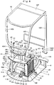
Fig. 3 is a perspective view of a state in which an engine, a heat exchanging device, a support member and a canopy are mounted on a revolving frame seen from a right rear side. -
Fig. 4 is an exploded perspective view of a state in which the canopy is separated from the revolving frame and the support member taken from a similar position to that ofFig. 3 . -
Fig. 5 is a perspective view of a state in which the engine, the heat exchanging device, the support member and a floor member are mounted on the revolving frame seen from the left front side. -
Fig. 6 is a perspective view of a state in which the floor member is removed from the revolving frame taken from a similar position to that ofFig. 5 . -
Fig. 7 is an exploded perspective view of a state in which the revolving frame, the heat exchanging device and the supporting member are separated from each other seen from the right rear side. -
Fig. 8 is an exploded perspective view of a state in which the revolving frame, the heat exchanging device and the supporting member are separated from each other seen from the left front side. -
Fig. 9 is a perspective view of a single body of the revolving frame seen from the left front side. -
Fig. 10 is a perspective view of the heat exchanging device inFig. 7 in an enlarged manner. -
Fig. 11 is a perspective view of the heat exchanging device shown inFig. 10 with a cooling fan seen from the engine side. -
Fig. 12 is a sectional view of the heat exchanging device and a cooling fan seen from an arrow XII-XII direction inFig. 11 . -
Fig. 13 is a sectional view of the heat exchanging device and the cooling fan seen from an arrow XIII-XIII direction inFig. 11 . -
Fig. 14 is an exploded perspective view of the heat exchanging device in an exploded state. -
Fig. 15 is an exploded perspective view showing the heat exchanging device and the cooling fan exploded from an opposite side toFig. 14 . -
Fig. 16 is a front view showing a shroud in an enlarged manner. -
Fig. 17 is a perspective view showing the shroud in an enlarged manner. - Hereinafter, a small-sized hydraulic excavator provided with an oil cooler and a radiator in a heat exchanging device is used as a typical example of a construction machine according to an embodiment of the present invention will be described in detail in accordance with
Figs. 1 to 17 . In this embodiment, a hydraulic excavator of a canopy type provided with a canopy covering an upper side of an operator's seat is exemplified. - In
Fig. 1 , thehydraulic excavator 1 is formed as a crawler-type construction machine according to this embodiment. Thishydraulic excavator 1 is a small-sized hydraulic excavator called a mini shovel. Thehydraulic excavator 1 is constituted by an automotivelower traveling structure 2, an upper revolvingstructure 3 rotatably mounted on thelower traveling structure 2, and aworking mechanism 4 provided on a front side of the upper revolvingstructure 3 in a front and rear direction, capable of moving upward/downward and performing an excavating work of earth and sand. - The upper revolving
structure 3 includes a revolvingframe 5 which will be described later, anengine 16, acooling fan 17, ahydraulic pump 18, aheat exchanging device 19, and asupport member 33. - The revolving
frame 5 is rotatably mounted on thelower traveling structure 2 and formed as a support structural body which is a major part of the upper revolvingstructure 3. As shown inFig. 9 , the revolvingframe 5 is constituted by arectangular bottom plate 6 formed of a thick flat plate, a left frontvertical plate 7 and a right frontvertical plate 8 installed upright having a substantial V-shape away from each other in a left and right direction on an upper surface side of thebottom plate 6, asupport bracket 9 provided on a front end part of each of the frontvertical plates working mechanism 4, apartition plate 10 extending in the left and right direction at a rear end position of each of the frontvertical plates bottom plate 6, a left rearvertical plate 11 installed upright so as to continue to a rear side of the left frontvertical plate 7 interposing thepartition plate 10, a right rearvertical plate 12 installed upright so as to continue to a rear side of the right frontvertical plate 8 interposing thepartition plate 10, a heat exchangingdevice mounting base 13 provided on an upper side of the right rearvertical plate 12 by extending in the front and rear direction, afloor mounting member 14 located on the front side of thebottom plate 6 and provided by extending on the upper side of each of the frontvertical plates bottom plate 6 and provided on thebottom plate 6, thepartition plate 10, and the left rearvertical plate 11. - A plurality of, for example, two,
bolt insertion holes 10A located on a right side in the left and right direction are provided in thepartition plate 10 at an interval in a vertical direction. These twobolt insertion holes 10A are for insertion of a framemember fixing bolt 27D for fixing afront side frame 22 of aframe member 20 constituting the below-describedheat exchanging device 19 to thepartition plate 10. - On the other hand, at a position of the
partition plate 10 closer to the left side, a plurality of, for example, two,female screw holes 10B located in the vicinity of the left rearvertical plate 11 at an interval in a vertical direction. Thisfemale screw hole 10B is formed by welding a nut coaxially with a through hole drilled in thepartition plate 10, for example (so-called weld nut). Other than that, as thefemale screw hole 10B, a female screw (thread) may be directly threaded on thepartition plate 10. The supportmember fixing bolt 37 for fixing a leftfront leg part 35 of thesupport member 33 which will be described later to thepartition plate 10 is screwed with thisfemale screw hole 10B. - The left rear
vertical plate 11 is constituted by a leftrear end plate 11A installed upright on a rear end portion of thebottom plate 6 so as to face thepartition plate 10 in the front and rear direction and a leftvertical plate member 11B installed upright by extending between thepartition plate 10 and the leftrear end plate 11A in the front and rear direction. A plurality of, for example, two, female screw holes 11A1 located in the vicinity of the left side of the leftvertical plate member 11B are provided in the leftrear end plate 11A at an interval in the vertical direction. This female screw hole 11A1 is formed by a weld nut, for example, similarly to thefemale screw hole 10B of thepartition plate 10 described above. The supportmember fixing bolt 37 for fixing the leftrear leg part 36 of thesupport member 33 to the left rearvertical plate 11 is screwed with these two female screw holes 11A1. - The right rear
vertical plate 12 is constituted by a rightrear end plate 12A installed upright on the rear end portion of thebottom plate 6 so as to face thepartition plate 10 in the front and rear direction and a rightvertical plate member 12B installed upright by extending between thepartition plate 10 and the rightrear end plate 12A in the front and rear direction. - The heat exchanging
device mounting base 13 is formed as a lengthy plate body mounted by extending on the rightvertical plate member 12B of the right rearvertical plate 12 by extending in the front and rear direction. In this heat exchangingdevice mounting base 13, a plurality of, for example, four,bolt insertion holes 13A are provided by penetrating in the vertical direction at an interval in the front and rear direction. - The
floor mounting member 14 constitutes a base on which a front side portion of thefloor member 38 which will be described later and aright front column 42D of acanopy 42 are mounted. Afemale screw hole 14A in which acanopy fixing bolt 43 for fixing theright front column 42D, which will be described later is screwed is provided on a right side position of thefloor mounting member 14. - Moreover, each of the
engine brackets 15 is arranged at a desired interval dimension in the front and rear direction and in the left and right direction. Each of theengine brackets 15 elastically supports theengine 16 through ananti-vibration mount 16A which will be described later. - As shown in
Figs. 3 ,4 , and6 , theengine 16 is provided on the rear side of the revolvingframe 5, and theengine 16 is arranged in a laterally placed state extending between thepartition plate 10 and therear end plates vertical plates engine 16 is mounted on each of theengine brackets 15 in an anti-vibration state through theanti-vibration mount 16A. The below-describedcooling fan 17 located on one side in the left and right direction, for example, on the right side is provided on thisengine 16. - The cooling
fan 17 is arranged on the right side which is one side of theengine 16 in the left and right direction, and the coolingfan 17 is mounted on the output shaft (not shown) of theengine 16. This coolingfan 17 is constituted as an axial flow suction fan for suctioning external air as cooling air and supplying it to theheat exchanging device 19 which will be described later by being rotated/driven together with the output shaft. Moreover, as shown inFigs. 11 and12 , the coolingfan 17 is constituted by acylindrical hub member 17A mounted on the output shaft of theengine 16 and a plurality ofblades 17B extending radially from the periphery of thehub member 17A. Each of theblades 17B is formed with each tip end having an arc shape so as to draw a circle by the tip ends. - Here, the cooling
fan 17 partially enters into theframe member 20 of theheat exchanging device 19 which will be described later. Specifically, each of theblades 17B of the coolingfan 17 is disposed in a state entering into theframe member 20 from anend surface 20A on theengine 16 side (hereinafter referred to as the engineside end surface 20A) with respect to theframe member 20. In this case, as shown inFigs. 12 and13 , an entering dimension of the coolingfan 17 is set to a dimension that approximately a half of each of theblades 17B in an axial direction dimension enters into theframe member 20 from the engineside end surface 20A of theframe member 20. Therefore, the coolingfan 17 can form a sufficient gap from anoil cooler 28 and aradiator 30 which will be described later. As a result, the coolingfan 17 can supply the cooling air to the entirety of theoil cooler 28 and theradiator 30 and can also prevent contact with theoil cooler 28 and theradiator 30. - The
hydraulic pump 18 is provided on the left side of theengine 16 which is the other side in the left and right direction. Thishydraulic pump 18 is for supplying the hydraulic oil to the hydraulic actuator provided on thelower traveling structure 2, the workingmechanism 4 and the like by being driven by theengine 16. - In the small-sized
hydraulic excavator 1, since an installation space on the revolvingframe 5 is small, in order to effectively utilize the limited space, an operator'sseat 39 which will be described later and the like are arranged on an upper side of theengine 16 and thehydraulic pump 18. In order to make this constitution possible, thesupport member 33 for supporting the operator'sseat 39 and the like is provided on an upper side position of theengine 16 on a rear side of the revolvingframe 5. - Subsequently, the
heat exchanging device 19 according to this embodiment for cooling the hydraulic oil for operating various hydraulic actuators and engine coolant for cooling theengine 16 will be described. Theframe member 20 constituting thisheat exchanging device 19 is used as a right side leg part of thesupport member 33 in the left and right direction. - The
heat exchanging device 19 is provided on the revolvingframe 5 by being located on the right side which is one side of theengine 16 in the left and right direction. As shown inFigs. 10 to 17 , thisheat exchanging device 19 is constituted by including theframe member 20, theoil cooler 28, theradiator 30, and theshroud 31 which will be described later. - The
frame member 20 is for forming an outer frame of theheat exchanging device 19 and thisframe member 20 is formed as a frame shaped body for supporting theoil cooler 28 and theradiator 30. That is, as shown inFigs. 14 and15 , theframe member 20 is assembled by using alower frame 21 located on a lower side, extending in the front and rear direction and mounted on the heat exchangingdevice mounting base 13 of the revolvingframe 5, a pair offront side frame 22 and arear side frame 23 extending to an upper side from both ends of thelower frame 21 in a length direction (front and rear direction), and anupper frame 24 extending at an upper position of each of the side frames 22 and 23 in the front and rear direction. In this case, theframe member 20 is assembled having a square frame shape as the whole. - In the square frame shaped
frame member 20, the cooling air by the coolingfan 17 is made to flow. In this case, in theframe member 20, the coolingfan 17 and theshroud 31 are arranged by being located on the engineside end surface 20A which is on theengine 16 side (downstream side) in a flow direction of the cooling air. - On the other hand, in the
frame member 20, a mountingsurface plate 25 having a substantially C-shape is provided on an outer side located on an upstream side of the cooling air, that is, on the right side which is an opposite side toengine 16. As shown inFig. 14 , the oil cooler 28 (oil cooler bracket 26) and the radiator 30 (radiator bracket 29) which will be described later are mounted on this mountingsurface plate 25. Moreover, a plurality of, for example, four, female screw holes 25A are provided in the mountingsurface plate 25 at intervals in the vertical direction or in the left and right direction. - Here, the
frame member 20 is formed having a square frame shape by appropriately fixing each of theframes 21 to 24 and the mountingsurface plate 25 formed by applying various kinds of machining to a steel plate by using welding means. Therefore, theframe member 20 has high strength that can support the operator'sseat 39, thecanopy 42 and the like or specifically, strength equal to each of theleg parts support member 33. - The
lower frame 21 of theframe member 20 is constituted by alower plate 21A made of a strip-shaped flat plate and asupport plate 21B having an L-shaped section provided by extending on thelower plate 21A in the length direction (front and rear direction) and supporting the mountingsurface plate 25. Moreover, tworadiator mounting holes 21C (only one of them is shown inFig. 14 ) located on an outer side (opposite side to the engine 16) from the mountingsurface plate 25 which is an outer side end surface and closer to the rear side in the length direction (front and rear direction) and fourfemale screw holes 21D made of weld nuts corresponding to each of thebolt insertion holes 13A provided in the heat exchangingdevice mounting base 13 of the revolvingframe 5 are provided in thelower plate 21A at an interval in the front and rear direction. - Moreover, in the
support plate 21B of thelower frame 21, its vertical plate portion constitutes a part of the engineside end surface 20A of theframe member 20. As shown inFig. 15 , for example, two,female screw holes 21E for mounting theshroud 31 are provided in thesupport plate 21B of thislower frame 21 at an interval in the front and rear direction. - The
front side frame 22 of theframe member 20 is constituted by a risingplate 22A extending in the vertical direction and asupport plate 22B having an L-shaped section mounted by extending on a rear surface of the risingplate 22A in the length direction (vertical direction) and supporting the mountingsurface plate 25. In the risingplate 22A, two female screw holes 22C are provided at positions corresponding to thebolt insertion holes 10A provided in thepartition plate 10 of the revolvingframe 5 closer to a lower side in the length direction (vertical direction). - Moreover, the
support plate 22B of thefront side frame 22 constitutes a part of the engineside end surface 20A of theframe member 20. As shown inFig. 15 , for example, twofemale screw holes 22D for mounting theshroud 31 are provided in thesupport plate 22B of thefront side frame 22 at an interval in the vertical direction. - The
rear side frame 23 of theframe member 20 is constituted by the risingplate 23A extending in the vertical direction as to face thefront side frame 22 in the front and rear direction and abent plate 23B formed by bending an end edge of the risingplate 23A on theengine 16 side and constituting a part of the engineside end surface 20A of theframe member 20. In the risingplate 23A, at an upper position, ascrew seat 23C for mounting theradiator bracket 29 which will be described later is provided on an opposite side to thebent plate 23B. Moreover, for example, twofemale screw holes 23D for mounting theshroud 31 are provided in thebent plate 23B at an interval in the vertical direction. - The
upper frame 24 of theframe member 20 is constituted by a flat plate shapedupper plate 24A and asupport plate 24B (see,Fig. 12 ) having an L-shaped section provided by extending in below theupper plate 24A in the length direction (front and rear direction) and supporting the mountingsurface plate 25. As shown inFigs. 10 and11 , a mounting plate portion 24A1 is provided by extending to the rear side more than therear side frame 23 on theupper plate 24A. In this mounting plate portion 24A1, a plurality of, for example, two,bolt insertion holes 24C are formed by being located closer to the left side which is theengine 16 side at an interval in the front and rear direction. The supportmember fixing bolt 37 for fixing afree end 34F of thehousing support base 34 of thesupport member 33 which will be described later is inserted into the twobolt insertion holes 24C. - Moreover, as shown in
Fig. 12 , in thesupport plate 24B of theupper frame 24, vertical plate portion of thesupport plate 24B constitutes a part of the engineside end surface 20A of theframe member 20. For example, two female screw holes 24D for mounting theshroud 31 are provided in thissupport plate 24B at an interval in the front and rear direction. - Here, the
frame member 20 has the square frame shaped engineside end surface 20A located on theengine 16 side. This engineside end surface 20A is formed by using thesupport plate 21B of thelower frame 21, thesupport plate 22B of thefront side frame 22, thebent plate 23B of therear side frame 23, and thesupport plate 24B of theupper frame 24. In this case, the engineside end surface 20A is formed as a square frame having the same planar shape as the whole. Theshroud 31 is detachably attached on this engineside end surface 20A. On the other hand, on the mountingsurface plate 25 of theframe member 20 which is the end surface on the opposite side to theengine 16, theoil cooler 28 and theradiator 30 are mounted. - The oil
cooler bracket 26 is mounted on the mountingsurface plate 25 of theframe member 20, and the oilcooler bracket 26 is formed as a C-shaped or U-shaped plate body opened on the rear side. Twofemale screw holes 26A located in an intermediate portion in the vertical direction are provided in the oilcooler bracket 26. On the other hand, female screw holes 26B are provided in upper and lower end portions of the oilcooler bracket 26 so as to be screwed from the front side. Female screw holes 26C are provided in the upper end portion of the oilcooler bracket 26 so as to be screwed from the right side in the left and right direction. Moreover,bolt insertion holes 26D are respectively provided in the intermediate portion and the lower portion of the oilcooler bracket 26 in the vertical direction. Here, the oilcooler bracket 26 can be fixed along the mountingsurface plate 25 by screwing an oil coolerbracket fixing bolt 27A inserted through each of thebolt insertion holes 26D with thefemale screw hole 25A of the mountingsurface plate 25. - The
oil cooler 28 is provided on theframe member 20 through the oilcooler bracket 26. This oil cooler 28 is for cooling the hydraulic oil to be returned from the hydraulic actuators provided on thelower traveling structure 2 and the workingmechanism 4 to the hydraulic oil tank (not shown). Theoil cooler 28 is formed of anupper tank 28A, alower tank 28B, and aheat radiation portion 28C, and mountingplates 28D in which the oilcooler fixing bolts 27B are inserted into the front and rear direction are provided at upper and lower positions of each of thetanks plates 28E are provided in theoil cooler 28 at front side positions of theheat radiation portion 28C (see,Fig. 15 ). - The
oil cooler 28 is mounted on the mountingsurface plate 25 through the oilcooler bracket 26. That is, the oilcooler fixing bolt 27B inserted into each of the mountingplates 28D is screwed with thefemale screw hole 26B of the oilcooler bracket 26, and the oilcooler fixing bolt 27B inserted into each of the mountingplates 28E is screwed with thefemale screw hole 26A of the oilcooler bracket 26 so that theoil cooler 28 can be mounted on the mountingsurface plate 25. - The
radiator bracket 29 is mounted on the upper right side (the mountingsurface plate 25 side) of theframe member 20, and theradiator bracket 29 constitutes an upper side fixing member for fixing an upper part of theradiator 30 to theframe member 20. In theradiator bracket 29, abolt insertion hole 29A located on an end portion in the front and rear direction and penetrating in the left and right direction is formed. On the other hand, aradiator mounting hole 29B is provided in theradiator bracket 29 at a position faced with each of theradiator mounting hole 21C of thelower frame 21 of theframe member 20 interposing theradiator 30. Theradiator bracket 29 is fixed to the upper part of theframe member 20. That is, the radiatorbracket fixing bolt 27C inserted into thebolt insertion hole 29A on the front side is screwed with thefemale screw hole 26C of the oilcooler bracket 26, and the radiatorbracket fixing bolt 27C inserted into thebolt insertion hole 29A on the rear side is screwed with thescrew seat 23C of therear side frame 23 so that theradiator bracket 29 can be mounted on theframe member 20. - The
radiator 30 is provided on theframe member 20 by being located on the rear side of theoil cooler 28, and theradiator 30 is for cooling the engine coolant whose temperature has risen by cooling theengine 16. Theradiator 30 is formed of anupper tank 30A, alower tank 30B, and aheat radiation portion 30C and each of thetanks engine 16. Theradiator 30 has theupper tank 30A supported by theradiator mounting hole 29B of theradiator bracket 29 through ananti-vibration member 30D and thelower tank 30B supported by theradiator mounting hole 21C of thelower frame 21 through theanti-vibration member 30D. - Here, the
oil cooler 28 is mounted on the mountingsurface plate 25 of theframe member 20 through the oilcooler bracket 26. Theradiator 30 is mounted on the mountingsurface plate 25 of theframe member 20 through theradiator bracket 29 and the oilcooler bracket 26. As a result, theoil cooler 28 and theradiator 30 are mounted on the mountingsurface plate 25 constituting the end surface on the opposite side to theengine 16 interposing the coolingfan 17. In this case, theoil cooler 28 and theradiator 30 are mounted in parallel so as to be juxtaposed in the front and rear direction in the flow direction of the cooling air (left and right direction). - It should be noted that the
oil cooler 28 and theradiator 30 are arranged at positions where a desired interval dimension can be ensured from the coolingfan 17. Therefore, if this interval dimension can be ensured, theoil cooler 28 and theradiator 30 can be arranged in a state partially entering in theframe member 20 beyond the mountingsurface plate 25. - On the other hand, a disposition position of the cooling
fan 17 with respect to theheat exchanging device 19 is at a position where each of theblades 17B enters into theframe member 20 from the mountingsurface plate 25 of theframe member 20 only by approximately a half of each of theblades 17B in the axial direction dimension. - Subsequently, a constitution of the
shroud 31 which is a feature portion of this embodiment provided on theheat exchanging device 19 will be described in detail. - The
shroud 31 forms a part of theheat exchanging device 19, and theshroud 31 is provided so as to surround an outer periphery of each of theblades 17B of the coolingfan 17 with respect to the engineside end surface 20A of theframe member 20. As a result, theshroud 31 covers a gap between the coolingfan 17 and the frame member 20 (engineside end surface 20A) so that a fan accommodating chamber 32 (see,Figs. 12 and13 ) can be formed among theframe member 20, theoil cooler 28, and theradiator 30. In thisfan accommodating chamber 32, the cooing air by the coolingfan 17 can be made to flow efficiently. - As shown in
Figs. 16 and17 , theshroud 31 is made of a substantially rectangular thin plate material, and acircular opening 31A for surrounding the coolingfan 17 is formed at its center position. Bolt insertion holes 31B are provided in a peripheral portion of theshroud 31 at positions corresponding the female screw holes 21E, 22D, 23D, and 24D, respectively, provided on the engineside end surface 20A (each of theframes frame member 20. Into these bolt insertion holes 31B, theshroud fixing bolts 31C are inserted, respectively. Moreover, on four side portions of theshroud 31,bent portions 31D are formed by bending end edges, and strength of theshroud 31 made of a thin plate material can be improved by thesebent portions 31D. - That is, it is only necessary that the
shroud 31 has a shape that can cover the gap between the coolingfan 17 and theframe member 20 and can be formed as a simple flat plate shape obtained only by applying drilling, bending or the like to a steel plate with a thin plate thickness, for example. Moreover, theshroud 31 can be detachably fixed to theframe member 20 by screwing theshroud fixing bolt 31C inserted into each of the bolt insertion holes 31B with each of the female screw holes 21E, 22D, 23D, and 24D of the engineside end surface 20A. - Regarding the
heat exchanging device 19 constituted as above, thelower frame 21 of theframe member 20 is placed on the heat exchangingdevice mounting base 13 of the revolvingframe 5 and as shown inFig. 7 , the framemember fixing bolt 27D inserted into thebolt insertion hole 13A from the lower side of thelower frame 21 in this state is screwed with thefemale screw hole 21D of thelower frame 21. Moreover, as shown inFig. 8 , the framemember fixing bolt 27D inserted into thebolt insertion hole 10A of thepartition plate 10 is screwed with thefemale screw hole 22C of thefront side frame 22. As a result, the heat exchanging device 19 (frame member 20) can be firmly fixed to the right rearvertical plate 12 of the revolvingframe 5. - Subsequently, constitution of the
support member 33 provided for supporting the operator'sseat 39, thecanopy 42 and the like on the upper side of theengine 16 will be described. - The
support member 33 is provided on the revolvingframe 5 in a state across theengine 16 from the upper side. Thissupport member 33 is for supporting the operator'sseat 39 and thecanopy 42. That is, thesupport member 33 is for arranging the operator'sseat 39, thecanopy 42 and the like, which will be described later, over theengine 16 in order to effectively use a limited space on the revolvingframe 5. Here, thesupport member 33 is constituted by thehousing support base 34, the leftfront leg part 35, and the leftrear leg part 36 which will be described later. - The
housing support base 34 is provided by extending in the left and right direction over theengine 16. As shown inFigs. 3 and4 , arear mounting plate 42A of thecanopy 42 which will be described later is mounted on thishousing support base 34. Thehousing support base 34 forms a box body which is lengthy in the left and right direction and flat in the vertical direction in order to obtain strength for supporting the rear side of thecanopy 42. Specifically, as shown inFigs. 6 and8 , thehousing support base 34 is formed of anupper plate 34A, alower plate 34B, afront plate 34C, and arear plate 34D. In theupper plate 34A of thehousing support base 34, a plurality of female screw holes 34A1, for example, six in total, by three each on right and left positions, are provided for fixing therear mounting plate 42A of thecanopy 42. - On the
lower plate 34B of thehousing support base 34, the leftfront leg part 35 and the leftrear leg part 36 which will be described later are mounted by being located on the left side which is the other side in the left and right direction. As a result, the left side portion of thehousing support base 34 becomes afixed end 34E fixed to each of theleg parts housing support base 34 becomes thefree end 34F on which no leg part is provided. - Here, in the
lower plate 34B of thehousing support base 34, a plurality of, for example, two, female screw holes 34B1 (shown by a dotted line inFigs. 7 and8 ) are provided by being located on thefree end 34F side. These two female screw holes 34B1 are arranged at an interval in the front and rear direction so as to correspond to thebolt insertion holes 24C provided in theupper frame 24 of theframe member 20 in theheat exchanging device 19. - The left
front leg part 35 is provided by being located on thefixed end 34E side which is the other side of thehousing support base 34 in the left and right direction. This leftfront leg part 35 has its upper end mounted on thelower plate 34B of thehousing support base 34 and the lower end mounted on thepartition plate 10 of the revolvingframe 5. That is, the leftfront leg part 35 is constituted by alateral leg 35A extending from thelower plate 34B of thehousing support base 34 to the front side, aninclined leg 35B extending diagonally to the lower side from the front end of thelateral leg 35A, and avertical leg 35C extending downward from the tip end of theinclined leg 35B. A plurality of, for example, two,bolt insertion holes 35D are provided in a lower side of thevertical leg 35C. These twobolt insertion holes 35D are arranged at an interval in the vertical direction so as to correspond to thefemale screw holes 10B provided in thepartition plate 10. - The left
rear leg part 36 is provided on thefixed end 34E side of thehousing support base 34 by being located on the rear side of the leftfront leg part 35. This leftrear leg part 36 is provided by extending in the vertical direction and has its upper end mounted on thelower plate 34B of thehousing support base 34 and the lower end mounted on the leftrear end plate 11A of the revolvingframe 5. A plurality of, for example, two,bolt insertion holes 36A are provided in a lower side of the leftrear leg part 36. These twobolt insertion holes 36A are arranged at an interval in the vertical direction so as to correspond to the female screw holes 11A1 provided in the leftrear end plate 11A of the left rearvertical plate 11. - As shown in
Fig. 6 , thesupport member 33 constituted as above is arranged so that the leftfront leg part 35 and the leftrear leg part 36 are placed across theengine 16 in the front and rear direction, and as shown inFigs. 7 and8 , the supportmember fixing bolt 37 inserted into thebolt insertion hole 35D of the leftfront leg part 35 is screwed with thefemale screw hole 10B provided in thepartition plate 10 of the revolvingframe 5. On the other hand, in the leftrear leg part 36, the supportmember fixing bolt 37 inserted into thebolt insertion hole 36A is screwed with the female screw hole 11A1 provided in the leftrear end plate 11A of the revolvingframe 5. In this state, thefree end 34F side of thehousing support base 34 is arranged on theframe member 20 of theheat exchanging device 19. - Then, the support
member fixing bolt 37 inserted into thebolt insertion hole 24C provided in the mounting plate portion 24A1 of theupper frame 24 of theframe member 20 from the lower side is screwed with the female screw hole 34B1 provided in thelower plate 34B of thehousing support base 34 so that thefree end 34F side of thehousing support base 34 can be fixed to the upper surface side of theframe member 20. In this case, theframe member 20 can support thehousing support base 34 in a horizontal state by matching its height dimension with the height dimension of each of theleg parts - As a result, as shown in
Figs. 4 and6 , thesupport member 33 can use theframe member 20 of theheat exchanging device 19 as the right side leg part for supporting thefree end 34F of thehousing support base 34. Thereby, thesupport member 33 can omit the right side leg part. - As shown in
Figs. 2 and5 , thefloor member 38 is provided on the revolvingframe 5 from the upper side to the front side of theengine 16. Thisfloor member 38 is formed having a step shape by a substantiallyflat footrest plate 38A extending to the rear side from thefloor mounting member 14 of the revolvingframe 5, a risingplate 38B rising from a rear part of thefootrest plate 38A, and an operator'sseat mounting plate 38C extending to the rear side from an upper part of the risingplate 38B. The operator'sseat mounting plate 38C on the rear side is mounted on theframe member 20 of theheat exchanging device 19 and on the leftfront leg part 35 of thesupport member 33, for example. - The operator's
seat 39 is provided on the operator'sseat mounting plate 38C of thefloor member 38, and the operator'sseat 39 is on which the operator is seated. As shown inFig. 2 , on both right and left sides of the operator'sseat 39, an operatinglever 40 for operation is disposed, and on the front side of the operator'sseat 39, an operating lever/pedal 41 for running is disposed. - The
canopy 42 is provided on the upper revolvingstructure 3, and thecanopy 42 constitutes a housing covering an upper part of the operator'sseat 39. In this embodiment, a three-column type canopy is used as thecanopy 42. As shown inFigs. 3 and4 , thecanopy 42 is constituted by including arear mounting plate 42A faced with thehousing support base 34 of thesupport member 33, a leftrear column 42B located on a left rear side of the operator'sseat 39 and extending upward from the upper surface of therear mounting plate 42A, a rightrear column 42C located on a right rear side of the operator'sseat 39 and extending upward from the upper surface of therear mounting plate 42A, aright front column 42D extending upward from a right side position of thefloor mounting member 14 of the revolvingframe 5, afront mounting plate 42E provided on a lower part of theright front column 42D and faced with thefloor mounting member 14, and aroof portion 42F provided on an upper part of each of thecolumns 42B to 42D. - Six bolt insertion holes 42A1 corresponding to each of the female screw holes 34A1 provided in the
upper plate 34A of thehousing support base 34 are provided in therear mounting plate 42A. On the other hand, a bolt insertion hole 42E1 corresponding to thefemale screw hole 14A of thefloor mounting member 14 is provided in thefront mounting plate 42E. - Here, in the
canopy 42, therear mounting plate 42A is placed on thehousing support base 34 of thesupport member 33, and the front mountingplate 42E is placed on thefloor mounting member 14 of the revolvingframe 5. In this state, thecanopy fixing bolt 43 inserted into each of the bolt insertion holes 42A1 of therear mounting plate 42A is screwed with each of the female screw holes 34A1 of theupper plate 34A of thehousing support base 34. As a result, the rear side of thecanopy 42 can be mounted on thesupport member 33. On the other hand, by screwing thecanopy fixing bolt 43 inserted into the bolt insertion hole 42E1 of the front mountingplate 42E with thefemale screw hole 14A of thefloor mounting member 14, the right front side of thecanopy 42 can be mounted on the revolvingframe 5. - A
counterweight 44 is mounted on a rear end portion of the revolvingframe 5. Thiscounterweight 44 is to take a weight balance with the workingmechanism 4 and is formed as a heavy article having a substantially arc shape. - An
exterior cover 45 is provided on the revolvingframe 5 from the rear side to the side of thecanopy 42. Thisexterior cover 45 is to cover theengine 16, theheat exchanging device 19 and the like mounted on the revolvingframe 5. - The
hydraulic excavator 1 according to this embodiment has the constitution described above, and then, an operation of thishydraulic excavator 1 will be described. - First, the operator gets onboard the upper revolving
structure 3 and is seated on the operator'sseat 39. In this state, by operating the operating lever/pedal 41 for running, the operator can drive thelower traveling structure 2 so as to advance or retreat thehydraulic excavator 1. On the other hand, the operator seated on the operator'sseat 39 can operate the workingmechanism 4 and the like so as to perform an excavating work of earth and sand by operating the operatinglever 40 for operation. - Here, a work procedure when the
heat exchanging device 19, thesupport member 33, and thecanopy 42 are to be mounted on the revolvingframe 5 constituting the upper revolvingstructure 3 will be described. The work procedure in this case exemplifies one of some work procedures, and mounting may be performed by using another work procedure. - As shown in
Fig. 7 , when theheat exchanging device 19 is to be mounted on the revolvingframe 5, thelower frame 21 of theframe member 20 is placed on the heat exchangingdevice mounting base 13 of the revolvingframe 5. In this state, the framemember fixing bolt 27D inserted into thebolt insertion hole 13A from the lower side of thelower frame 21 is screwed with thefemale screw hole 21D of thelower frame 21. Moreover, as shown inFig. 8 , the framemember fixing bolt 27D inserted into thebolt insertion hole 10A of thepartition plate 10 is screwed with thefemale screw hole 22C of thefront side frame 22. As a result, theheat exchanging device 19 can be mounted on the revolvingframe 5. - Here, the arrangement relation of the cooling
fan 17, theframe member 20, theoil cooler 28, theradiator 30, and theshroud 31 when theheat exchanging device 19 is mounted on the revolvingframe 5 will be described. As shown inFigs. 12 and13 , the coolingfan 17 provided on theengine 16 is disposed in the state in which each of theblades 17B enters into theframe member 20 from the engineside end surface 20A (shroud 31) of theframe member 20 by approximately a half thereof. On the other hand, theoil cooler 28 and theradiator 30 are mounted on the mountingsurface plate 25 which is an end surface on the opposite side to theengine 16 interposing the coolingfan 17 with respect to theframe member 20. In this case, theoil cooler 28 and theradiator 30 are arranged with the desired interval dimension from the coolingfan 17 so that they do not interfere with the coolingfan 17 and can receive the cooling air by the coolingfan 17 on the entirety. - On the other hand, once the
heat exchanging device 19 is mounted on the revolvingframe 5, a mounting work of thesupport member 33 is started. In this case, thesupport member 33 is arranged so that the leftfront leg part 35 and the leftrear leg part 36 are placed across theengine 16 in the front and rear direction, and the supportmember fixing bolt 37 inserted into thebolt insertion hole 35D of the leftfront leg part 35 is screwed with thefemale screw hole 10B provided in thepartition plate 10 of the revolvingframe 5. As a result, the leftfront leg part 35 can be mounted on thepartition plate 10 of the revolvingframe 5. - On the other hand, in the left
rear leg part 36, the supportmember fixing bolt 37 inserted into thebolt insertion hole 36A is screwed with the female screw hole 11A1 provided in the leftrear end plate 11A of the left rearvertical plate 11. As a result, the leftrear leg part 36 can be mounted on the left rearvertical plate 11 of the revolvingframe 5. - In this state, the
free end 34F side of thehousing support base 34 can be arranged on theframe member 20 of theheat exchanging device 19. Then, the supportmember fixing bolt 37 is inserted into thebolt insertion hole 24C provided in the mounting plate portion 24A1 of theupper frame 24 of theframe member 20 from the lower side, and this fixingbolt 37 is screwed with the female screw hole 34B1 provided in thelower plate 34B of thehousing support base 34. As a result, thefree end 34F side of thehousing support base 34 can be fixed to the upper surface side of theframe member 20, and thesupport member 33 can be stably mounted on the revolvingframe 5 by using theframe member 20 as the right side leg part. - Subsequently, as shown in
Fig. 4 , when thecanopy 42 is to be mounted, therear mounting plate 42A is placed on thehousing support base 34 of thesupport member 33, and the front mountingplate 42E is placed on thefloor mounting member 14 of the revolvingframe 5. In this state, thecanopy fixing bolt 43 inserted into each of the bolt insertion holes 42A1 of therear mounting plate 42A is screwed with each of the female screw holes 34A1 of theupper plate 34A of thehousing support base 34. As a result, the rear side of thecanopy 42 can be mounted on thesupport member 33. On the other hand, thecanopy fixing bolt 43 inserted into the bolt insertion hole 42E1 of the front mountingplate 42E is screwed with thefemale screw hole 14A of thefloor mounting member 14. As a result, the right front side of thecanopy 42 can be mounted on the revolvingframe 5. - As described above, according to this embodiment, the cooling
fan 17 mounted on the output shaft of theengine 16 is disposed so that each of theblades 17B enters into theframe member 20 from the engineside end surface 20A (shroud 31) of theframe member 20 by approximately a half in the axial direction dimension with respect to theframe member 20 of theheat exchanging device 19. On the other hand, theoil cooler 28 and theradiator 30 are mounted on the mountingsurface plate 25 which is the end surface on the opposite side to theframe member 20 in the state with the desired interval dimension from the coolingfan 17. - With the arrangement structure as above, it is constituted such that the
shroud 31 surrounding the outer periphery of eachblade 17B of the coolingfan 17 is mounted on the engineside end surface 20A of theframe member 20. As a result, thisshroud 31 can form thefan accommodating chamber 32 among thefame member 20, theoil cooler 28, and theradiator 30. With this constitution, interference among the coolingfan 17, theoil cooler 28, and theradiator 30 can be prevented and moreover, the cooling air by the coolingfan 17 can be supplied to the entireties of theoil cooler 28 and theradiator 30. - Therefore, it is only necessary that the
shroud 31 has a shape that can cover the gap between the coolingfan 17 and theframe member 20, and it can be formed having a simple flat plate shape. As a result, since the shape of theshroud 31 is simplified, the size, the weight, and the manufacturing cost of theheat exchanging device 19 can be reduced and moreover, assembling workability, the maintenance workability and the like can be improved. - Moreover, the
shroud 31 can be easily manufactured only by machining thecircular opening 31A for surrounding the coolingfan 17, thebolt insertion holes 31B and the like in the rectangular plate body. Moreover, since theshroud 31 is constituted to have its periphery detachably fixed to theframe member 20 by using theshroud fixing bolt 31C, the cleaning work and the inspection work of theoil cooler 28 and theradiator 30 and the replacement work of the fan belt (not shown) rounded to the output shaft of theengine 16 and the like can be performed easily. - On the other hand, since the
frame member 20 of theheat exchanging device 19 is for supporting theoil cooler 28 and theradiator 30, it has rigidity and can support a heavy article. On the other hand, thesupport member 33 is constituted by thehousing support base 34 provided by extending on the upper side of theengine 16 in the left and right direction and the leftfront leg part 35 and the leftrear leg part 36 having the upper ends mounted at the left side positions of thehousing support base 34 in the left and right direction and the lower ends mounted on the revolvingframe 5 across theengine 16 in the front and rear direction. As a result, in thehousing support base 34 of thesupport member 33, the right side in the left and right direction is formed as thefree end 34F. In addition, thesupport member 33 is constituted such that thefree end 34F of thishousing support base 34 is mounted on theframe member 20 of theheat exchanging device 19. - Therefore, even if the leg part on the right side (heat exchanging
device 19 side) in the left and right direction is omitted and each of theleg parts support member 33 can stably support thehousing support base 34 in the state supported on the both sides by each of theleg parts frame member 20 on the right side by using theframe member 20 of theheat exchanging device 19. - As a result, when the
support member 33 is to be mounted on the revolvingframe 5, by mounting each of theleg parts fixed end 34E of thehousing support base 34 on the revolvingframe 5, and by mounting thefree end 34F side of thehousing support base 34 on theframe member 20 of theheat exchanging device 19, thesupport member 33 can be mounted on the revolvingframe 5. As a result, the number of work processes when thesupport member 33 is mounted on the revolvingframe 5 can be reduced, and assembling workability can be improved. Moreover, the installation space on the revolvingframe 5 can be effectively used for a portion of omission of the leg part on the right side, and the size of the upper revolvingstructure 3 can be reduced. Furthermore, since the weight of thesupport member 33 can be reduced for a portion of omission of the leg part on the right side, the weight of thehydraulic excavator 1 can be reduced. - On the other hand, the
frame member 20 of theheat exchanging device 19 is formed having a square frame body by using thelower frame 21, each of the side frames 22 and 23, and theupper frame 24. As a result, thefree end 34F of thehousing support base 34 constituting thesupport member 33 can be mounted on the upper surface side of theupper frame 24 by using the supportmember fixing bolt 37. In this case, as compared with the case in which the lower end of the leg part is mounted on the revolvingframe 5, thefree end 34F of thehousing support base 34 can be mounted not on a deep lower part but at an upper part position which can be easily reached. In this point,the assembling workability can be improved. - Moreover, since the
frame member 20 of theheat exchanging device 19 can be used as the right side leg part of thesupport member 33, thehousing support base 34 can be firmly supported by using thisframe member 20. As a result, supporting strength of thecanopy 42 against roll-over, falling, a collision of a dropped object and the like can be improved, and reliability of thehydraulic excavator 1 can be improved. - According to this embodiment, the case in which the
oil cooler 28 and theradiator 30 are mounted on the mountingsurface plate 25 of theframe member 20 through therespective brackets oil cooler 28, theradiator 30 and the coolingfan 17, for example, it may be so constituted that theoil cooler 28 and theradiator 30 are arranged in a state a part of each of them enters into theframe member 20 beyond the mountingsurface plate 25 constituting the end surface on the opposite side to theengine 16. - According to the embodiment, the case in which the
oil cooler 28 and theradiator 30 are provided in theheat exchanging device 19 is described as an example. However, the present invention is not limited thereto, and it may be so constituted that other than theoil cooler 28 and theradiator 30, an intercooler, a condenser of an air conditioning device, a fuel cooler and the like, for example, are provided. - According to the embodiment, the case in which the three-
column type canopy 42 including the threecolumns 42B to 42D is provided as the housing is exemplified. However, the present invention is not limited to that, it may be so constituted that a canopy including one, two or four or more leg parts is used as the housing. On the other hand, a cab covering the periphery and the upper part of the operator'sseat 39 can be also applied as the housing. - In the embodiment, the crawler-type small-sized
hydraulic excavator 1 is described as an example of a construction machine. However, the present invention is not limited to that and it may be applied to a small-sized hydraulic excavator including a wheel-type lower traveling structure, for example. Moreover, it can be widely applied to other construction machines such as a small-sized hydraulic crane and the like. -
- 1:
- Hydraulic excavator (Construction machine)
- 2:
- Lower traveling structure
- 3:
- Upper revolving structure
- 4:
- Working mechanism
- 5:
- Revolving frame
- 16:
- Engine
- 17:
- Cooling fan
- 17A:
- Hub member
- 17B:
- Blade
- 18:
- Hydraulic pump
- 19:
- Heat exchanging device
- 20:
- Frame member
- 20A:
- Engine side end surface
- 21:
- Lower frame
- 22:
- Front side frame
- 23:
- Rear side frame
- 24:
- Upper frame
- 25:
- Mounting surface plate
- 27A to 27D, 31C, 37, 43:
- Fixing bolt
- 28:
- Oil cooler
- 30:
- Radiator
- 31:
- Shroud
- 31A:
- Circular opening
- 32:
- Fan accommodating chamber
- 33:
- Support member
- 34:
- Housing support base
- 34E:
- Fixed end
- 34F:
- Free end
- 35:
- Left front leg part
- 36:
- Left rear leg part
Claims (3)
- A construction machine comprising:an automotive lower traveling structure (2);an upper revolving structure (3) rotatably mounted on said lower traveling structure (2); anda working mechanism (4) provided on a front side of said upper revolving structure (3), capable of moving upward/downward; whereinsaid upper revolving structure (3) comprises:a revolving frame (5) forming a support structural body;an engine (16) mounted on a rear side of said revolving frame (5) in a laterally placed state extending in a left and right direction;a cooling fan (17) having a plurality of blades (17B) around a hub member (17A) located on one side of said engine (16) in the left and right direction and mounted on an output shaft of said engine (16) and generating cooling air by being driven by said engine (16);a hydraulic pump (18) provided on the other side of said engine (16) in the left and right direction and supplying hydraulic oil to a hydraulic actuator by being driven by said engine (16); anda heat exchanging device (19) including an oil cooler (28) provided on said revolving frame (5) so as to face said cooling fan (17) and cooling said hydraulic oil, and a radiator (30) for cooling coolant of said engine (16), characterized in that:said heat exchanging device (19) includes a fame member (20) assembled having a square frame shape by using a lower frame (21) located on a lower side, extending in a front and rear direction of said upper revolving structure (3) and mounted on said revolving frame (5), a pair of side frames (22, 23) extending to an upper side from both ends of said lower frame (21) in a length direction, and an upper frame (24) extending in the front and rear direction on an upper part of each of said side frames (22, 23);said cooling fan (17) is disposed in a state in which each of said blades (17B) enters into said frame member (20) from an end surface (20A) on said engine side with respect to said frame member (20);said oil cooler (28) and said radiator (30) are mounted on an opposite side to said engine (16) interposing said cooling fan (17) with respect to said frame member (20); anda flat plate shaped shroud (31) surrounding an outer periphery of each of said blades (17B) of said cooling fan (17) and forming a fan accommodating chamber (32) among said frame member (20), said oil cooler (28), and said radiator (30) is provided on said engine side end surface (20A) of said frame member (20).
- The construction machine according to claim 1, wherein said shroud (31) is formed as a rectangular plate body having a circular opening (31A) for surrounding said cooling fan (17), and a periphery of said shroud is detachably attached to said engine side end surface (20A) of said frame member (20).
- The construction machine according to claim 1, wherein a support member (33) formed of a housing support base (34) extending on an upper side of said engine (16) in the left and right direction and formed of front and rear leg parts (35, 36) each having an upper end mounted at a position on the other side of said housing support base (34) in the left and right direction and a lower end mounted on said revolving frame (5) across said engine (16) in the front and rear direction is provided on said revolving frame (5); and
said housing support base (34) of said support member (33) having one side which is a free end (34F) in the left and right direction is mounted on said frame member (20) of said heat exchanging device (19).
Applications Claiming Priority (2)
| Application Number | Priority Date | Filing Date | Title |
|---|---|---|---|
| JP2014032860A JP6040187B2 (en) | 2014-02-24 | 2014-02-24 | Construction machinery |
| PCT/JP2014/082407 WO2015125380A1 (en) | 2014-02-24 | 2014-12-08 | Construction machine |
Publications (3)
| Publication Number | Publication Date |
|---|---|
| EP3112538A1 true EP3112538A1 (en) | 2017-01-04 |
| EP3112538A4 EP3112538A4 (en) | 2017-11-08 |
| EP3112538B1 EP3112538B1 (en) | 2019-06-26 |
Family
ID=53877909
Family Applications (1)
| Application Number | Title | Priority Date | Filing Date |
|---|---|---|---|
| EP14883398.1A Active EP3112538B1 (en) | 2014-02-24 | 2014-12-08 | Construction machine |
Country Status (5)
| Country | Link |
|---|---|
| US (1) | US10106954B2 (en) |
| EP (1) | EP3112538B1 (en) |
| JP (1) | JP6040187B2 (en) |
| CN (1) | CN105492699B (en) |
| WO (1) | WO2015125380A1 (en) |
Families Citing this family (10)
| Publication number | Priority date | Publication date | Assignee | Title |
|---|---|---|---|---|
| JP6454142B2 (en) * | 2014-11-28 | 2019-01-16 | 日立建機株式会社 | Construction machinery |
| JP6672087B2 (en) * | 2016-06-21 | 2020-03-25 | 株式会社クボタ | Work machine |
| US9981545B1 (en) * | 2017-03-29 | 2018-05-29 | Deere & Company | Zero turning radius mower radiator mounting structure |
| JP6734223B2 (en) * | 2017-05-12 | 2020-08-05 | 日立建機株式会社 | Hydraulic excavator |
| US11413955B2 (en) | 2018-06-29 | 2022-08-16 | Kubota Corporation | Working machine |
| JP2020006941A (en) * | 2018-06-29 | 2020-01-16 | 株式会社クボタ | Work machine |
| EP3815949B1 (en) * | 2018-06-29 | 2023-12-06 | Kubota Corporation | Work machine |
| US10688845B2 (en) * | 2018-08-13 | 2020-06-23 | Caterpillar Paving Products Inc. | Cooling package for a machine |
| JP2022014680A (en) * | 2020-07-07 | 2022-01-20 | ヤマハ発動機株式会社 | vehicle |
| US11821166B2 (en) * | 2020-07-22 | 2023-11-21 | Caterpillar Underground Mining Pty. Ltd. | Internal support structure for underground battery machines |
Family Cites Families (23)
| Publication number | Priority date | Publication date | Assignee | Title |
|---|---|---|---|---|
| JP3523018B2 (en) * | 1997-06-03 | 2004-04-26 | 日立建機株式会社 | Swiveling construction machine |
| JP4450298B2 (en) * | 2000-01-12 | 2010-04-14 | 株式会社小松製作所 | Engine cooling air passage for construction machinery |
| JP2001348909A (en) * | 2000-06-02 | 2001-12-21 | Shin Caterpillar Mitsubishi Ltd | Construction machinery |
| JP4213479B2 (en) * | 2003-01-14 | 2009-01-21 | 日立建機株式会社 | Construction machinery |
| JP3952972B2 (en) * | 2003-03-07 | 2007-08-01 | コベルコ建機株式会社 | Construction machine cooling system |
| CN100482901C (en) * | 2004-03-29 | 2009-04-29 | 株式会社久保田 | Swiveling utility machine having swivel deck |
| DE102004018036A1 (en) * | 2004-04-08 | 2005-11-10 | Behr Gmbh & Co. Kg | cooling system |
| WO2008015798A1 (en) * | 2006-08-02 | 2008-02-07 | Komatsu Ltd. | Hybrid working vehicle |
| JP2009019585A (en) * | 2007-07-12 | 2009-01-29 | Caterpillar Japan Ltd | Tip clearance adjustment structure for cooling fan in working machine |
| CN101177120B (en) | 2007-12-01 | 2010-04-14 | 陈基镛 | Multiple medium modularization integration cooling units for automobile |
| WO2009101935A1 (en) * | 2008-02-15 | 2009-08-20 | Hitachi Construction Machinery Co., Ltd. | Construction machine |
| JP4686565B2 (en) * | 2008-03-31 | 2011-05-25 | 株式会社クボタ | Superstructure of work equipment |
| JP2010168739A (en) | 2009-01-20 | 2010-08-05 | Hitachi Constr Mach Co Ltd | Construction machinery |
| JP5234693B2 (en) * | 2009-10-16 | 2013-07-10 | 日立建機株式会社 | Construction machinery |
| JP5172898B2 (en) * | 2010-06-15 | 2013-03-27 | 日立建機株式会社 | Electric construction machine |
| JP5821221B2 (en) * | 2011-03-08 | 2015-11-24 | コベルコ建機株式会社 | Construction machine cooling system |
| JP5442672B2 (en) * | 2011-06-21 | 2014-03-12 | 日立建機株式会社 | Construction machinery |
| US9255381B2 (en) * | 2011-12-26 | 2016-02-09 | Hitachi Construction Machinery Co., Ltd. | Construction machine |
| EP3009284B1 (en) * | 2013-08-09 | 2019-08-14 | Komatsu Ltd. | Working vehicle |
| US9540788B2 (en) * | 2013-08-09 | 2017-01-10 | Komatsu Ltd. | Work vehicle |
| JP5819891B2 (en) | 2013-08-21 | 2015-11-24 | 日立建機株式会社 | Construction machinery |
| JP6132273B2 (en) * | 2014-07-28 | 2017-05-24 | 日立建機株式会社 | Hybrid work machine |
| JP6078696B2 (en) * | 2015-08-24 | 2017-02-08 | 株式会社小松製作所 | Hybrid work vehicle |
-
2014
- 2014-02-24 JP JP2014032860A patent/JP6040187B2/en active Active
- 2014-12-08 US US14/915,689 patent/US10106954B2/en active Active
- 2014-12-08 EP EP14883398.1A patent/EP3112538B1/en active Active
- 2014-12-08 WO PCT/JP2014/082407 patent/WO2015125380A1/en active Application Filing
- 2014-12-08 CN CN201480047628.5A patent/CN105492699B/en active Active
Also Published As
| Publication number | Publication date |
|---|---|
| EP3112538B1 (en) | 2019-06-26 |
| WO2015125380A1 (en) | 2015-08-27 |
| CN105492699B (en) | 2018-01-05 |
| EP3112538A4 (en) | 2017-11-08 |
| US10106954B2 (en) | 2018-10-23 |
| JP2015158079A (en) | 2015-09-03 |
| US20160369478A1 (en) | 2016-12-22 |
| CN105492699A (en) | 2016-04-13 |
| JP6040187B2 (en) | 2016-12-07 |
Similar Documents
| Publication | Publication Date | Title |
|---|---|---|
| EP3112538B1 (en) | Construction machine | |
| US9255381B2 (en) | Construction machine | |
| JP5568042B2 (en) | Work vehicle | |
| JP4981050B2 (en) | Hybrid work vehicle | |
| JP5677157B2 (en) | Tractor | |
| KR101059337B1 (en) | Construction machinery | |
| EP2949818B1 (en) | Construction machine | |
| EP2840190A2 (en) | Construction machine | |
| JP6594968B2 (en) | Work vehicle | |
| EP1887147A2 (en) | Construction machine | |
| EP3101181A1 (en) | Construction machine | |
| KR20150006464A (en) | Exhaust treatment unit, and method for attaching and detaching exhaust treatment unit | |
| JP2008019616A (en) | Motor-driven construction machine | |
| CN100408767C (en) | Construction mechanism | |
| JP2015140643A (en) | Construction machine | |
| EP3366899A1 (en) | Utility vehicle, and method for adjusting position of movable part of utility vehicle | |
| JP4982167B2 (en) | Wheel loader | |
| JP5845158B2 (en) | Construction machinery | |
| JP6913660B2 (en) | Construction machinery | |
| JP4885787B2 (en) | Construction machinery | |
| WO2021020168A1 (en) | Driving device and mount for construction machine | |
| JP2012219719A (en) | Construction machine | |
| WO2014024324A1 (en) | Bulldozer | |
| JP5253272B2 (en) | Electric construction machine | |
| JP2019112029A (en) | Heat exchange device |
Legal Events
| Date | Code | Title | Description |
|---|---|---|---|
| PUAI | Public reference made under article 153(3) epc to a published international application that has entered the european phase |
Free format text: ORIGINAL CODE: 0009012 |
|
| STAA | Information on the status of an ep patent application or granted ep patent |
Free format text: STATUS: REQUEST FOR EXAMINATION WAS MADE |
|
| 17P | Request for examination filed |
Effective date: 20160225 |
|
| AK | Designated contracting states |
Kind code of ref document: A1 Designated state(s): AL AT BE BG CH CY CZ DE DK EE ES FI FR GB GR HR HU IE IS IT LI LT LU LV MC MK MT NL NO PL PT RO RS SE SI SK SM TR |
|
| AX | Request for extension of the european patent |
Extension state: BA ME |
|
| RAP1 | Party data changed (applicant data changed or rights of an application transferred) |
Owner name: HITACHI CONSTRUCTION MACHINERY TIERRA CO., LTD. |
|
| DAX | Request for extension of the european patent (deleted) | ||
| A4 | Supplementary search report drawn up and despatched |
Effective date: 20171009 |
|
| RIC1 | Information provided on ipc code assigned before grant |
Ipc: E02F 9/00 20060101AFI20171002BHEP Ipc: F01P 11/10 20060101ALI20171002BHEP Ipc: B60K 11/04 20060101ALI20171002BHEP Ipc: E02F 3/32 20060101ALI20171002BHEP Ipc: E02F 9/08 20060101ALI20171002BHEP Ipc: F01P 3/18 20060101ALI20171002BHEP |
|
| GRAJ | Information related to disapproval of communication of intention to grant by the applicant or resumption of examination proceedings by the epo deleted |
Free format text: ORIGINAL CODE: EPIDOSDIGR1 |
|
| STAA | Information on the status of an ep patent application or granted ep patent |
Free format text: STATUS: GRANT OF PATENT IS INTENDED |
|
| GRAP | Despatch of communication of intention to grant a patent |
Free format text: ORIGINAL CODE: EPIDOSNIGR1 |
|
| INTG | Intention to grant announced |
Effective date: 20190108 |
|
| RIN1 | Information on inventor provided before grant (corrected) |
Inventor name: KAWAMOTO, JUNYA Inventor name: KOKURYOU, OSAMU Inventor name: UEDA, MASAYA |
|
| GRAS | Grant fee paid |
Free format text: ORIGINAL CODE: EPIDOSNIGR3 |
|
| GRAA | (expected) grant |
Free format text: ORIGINAL CODE: 0009210 |
|
| STAA | Information on the status of an ep patent application or granted ep patent |
Free format text: STATUS: THE PATENT HAS BEEN GRANTED |
|
| AK | Designated contracting states |
Kind code of ref document: B1 Designated state(s): AL AT BE BG CH CY CZ DE DK EE ES FI FR GB GR HR HU IE IS IT LI LT LU LV MC MK MT NL NO PL PT RO RS SE SI SK SM TR |
|
| REG | Reference to a national code |
Ref country code: GB Ref legal event code: FG4D |
|
| REG | Reference to a national code |
Ref country code: CH Ref legal event code: EP |
|
| REG | Reference to a national code |
Ref country code: AT Ref legal event code: REF Ref document number: 1148434 Country of ref document: AT Kind code of ref document: T Effective date: 20190715 |
|
| REG | Reference to a national code |
Ref country code: DE Ref legal event code: R096 Ref document number: 602014049289 Country of ref document: DE |
|
| REG | Reference to a national code |
Ref country code: IE Ref legal event code: FG4D |
|
| REG | Reference to a national code |
Ref country code: NL Ref legal event code: MP Effective date: 20190626 |
|
| PG25 | Lapsed in a contracting state [announced via postgrant information from national office to epo] |
Ref country code: HR Free format text: LAPSE BECAUSE OF FAILURE TO SUBMIT A TRANSLATION OF THE DESCRIPTION OR TO PAY THE FEE WITHIN THE PRESCRIBED TIME-LIMIT Effective date: 20190626 Ref country code: LT Free format text: LAPSE BECAUSE OF FAILURE TO SUBMIT A TRANSLATION OF THE DESCRIPTION OR TO PAY THE FEE WITHIN THE PRESCRIBED TIME-LIMIT Effective date: 20190626 Ref country code: FI Free format text: LAPSE BECAUSE OF FAILURE TO SUBMIT A TRANSLATION OF THE DESCRIPTION OR TO PAY THE FEE WITHIN THE PRESCRIBED TIME-LIMIT Effective date: 20190626 Ref country code: NO Free format text: LAPSE BECAUSE OF FAILURE TO SUBMIT A TRANSLATION OF THE DESCRIPTION OR TO PAY THE FEE WITHIN THE PRESCRIBED TIME-LIMIT Effective date: 20190926 Ref country code: AL Free format text: LAPSE BECAUSE OF FAILURE TO SUBMIT A TRANSLATION OF THE DESCRIPTION OR TO PAY THE FEE WITHIN THE PRESCRIBED TIME-LIMIT Effective date: 20190626 Ref country code: SE Free format text: LAPSE BECAUSE OF FAILURE TO SUBMIT A TRANSLATION OF THE DESCRIPTION OR TO PAY THE FEE WITHIN THE PRESCRIBED TIME-LIMIT Effective date: 20190626 |
|
| REG | Reference to a national code |
Ref country code: LT Ref legal event code: MG4D |
|
| PG25 | Lapsed in a contracting state [announced via postgrant information from national office to epo] |
Ref country code: BG Free format text: LAPSE BECAUSE OF FAILURE TO SUBMIT A TRANSLATION OF THE DESCRIPTION OR TO PAY THE FEE WITHIN THE PRESCRIBED TIME-LIMIT Effective date: 20190926 Ref country code: RS Free format text: LAPSE BECAUSE OF FAILURE TO SUBMIT A TRANSLATION OF THE DESCRIPTION OR TO PAY THE FEE WITHIN THE PRESCRIBED TIME-LIMIT Effective date: 20190626 Ref country code: LV Free format text: LAPSE BECAUSE OF FAILURE TO SUBMIT A TRANSLATION OF THE DESCRIPTION OR TO PAY THE FEE WITHIN THE PRESCRIBED TIME-LIMIT Effective date: 20190626 Ref country code: GR Free format text: LAPSE BECAUSE OF FAILURE TO SUBMIT A TRANSLATION OF THE DESCRIPTION OR TO PAY THE FEE WITHIN THE PRESCRIBED TIME-LIMIT Effective date: 20190927 |
|
| REG | Reference to a national code |
Ref country code: AT Ref legal event code: MK05 Ref document number: 1148434 Country of ref document: AT Kind code of ref document: T Effective date: 20190626 |
|
| PG25 | Lapsed in a contracting state [announced via postgrant information from national office to epo] |
Ref country code: EE Free format text: LAPSE BECAUSE OF FAILURE TO SUBMIT A TRANSLATION OF THE DESCRIPTION OR TO PAY THE FEE WITHIN THE PRESCRIBED TIME-LIMIT Effective date: 20190626 Ref country code: NL Free format text: LAPSE BECAUSE OF FAILURE TO SUBMIT A TRANSLATION OF THE DESCRIPTION OR TO PAY THE FEE WITHIN THE PRESCRIBED TIME-LIMIT Effective date: 20190626 Ref country code: SK Free format text: LAPSE BECAUSE OF FAILURE TO SUBMIT A TRANSLATION OF THE DESCRIPTION OR TO PAY THE FEE WITHIN THE PRESCRIBED TIME-LIMIT Effective date: 20190626 Ref country code: AT Free format text: LAPSE BECAUSE OF FAILURE TO SUBMIT A TRANSLATION OF THE DESCRIPTION OR TO PAY THE FEE WITHIN THE PRESCRIBED TIME-LIMIT Effective date: 20190626 Ref country code: CZ Free format text: LAPSE BECAUSE OF FAILURE TO SUBMIT A TRANSLATION OF THE DESCRIPTION OR TO PAY THE FEE WITHIN THE PRESCRIBED TIME-LIMIT Effective date: 20190626 Ref country code: RO Free format text: LAPSE BECAUSE OF FAILURE TO SUBMIT A TRANSLATION OF THE DESCRIPTION OR TO PAY THE FEE WITHIN THE PRESCRIBED TIME-LIMIT Effective date: 20190626 Ref country code: PT Free format text: LAPSE BECAUSE OF FAILURE TO SUBMIT A TRANSLATION OF THE DESCRIPTION OR TO PAY THE FEE WITHIN THE PRESCRIBED TIME-LIMIT Effective date: 20191028 |
|
| PG25 | Lapsed in a contracting state [announced via postgrant information from national office to epo] |
Ref country code: SM Free format text: LAPSE BECAUSE OF FAILURE TO SUBMIT A TRANSLATION OF THE DESCRIPTION OR TO PAY THE FEE WITHIN THE PRESCRIBED TIME-LIMIT Effective date: 20190626 Ref country code: IS Free format text: LAPSE BECAUSE OF FAILURE TO SUBMIT A TRANSLATION OF THE DESCRIPTION OR TO PAY THE FEE WITHIN THE PRESCRIBED TIME-LIMIT Effective date: 20191026 Ref country code: ES Free format text: LAPSE BECAUSE OF FAILURE TO SUBMIT A TRANSLATION OF THE DESCRIPTION OR TO PAY THE FEE WITHIN THE PRESCRIBED TIME-LIMIT Effective date: 20190626 |
|
| PG25 | Lapsed in a contracting state [announced via postgrant information from national office to epo] |
Ref country code: TR Free format text: LAPSE BECAUSE OF FAILURE TO SUBMIT A TRANSLATION OF THE DESCRIPTION OR TO PAY THE FEE WITHIN THE PRESCRIBED TIME-LIMIT Effective date: 20190626 |
|
| PG25 | Lapsed in a contracting state [announced via postgrant information from national office to epo] |
Ref country code: DK Free format text: LAPSE BECAUSE OF FAILURE TO SUBMIT A TRANSLATION OF THE DESCRIPTION OR TO PAY THE FEE WITHIN THE PRESCRIBED TIME-LIMIT Effective date: 20190626 Ref country code: PL Free format text: LAPSE BECAUSE OF FAILURE TO SUBMIT A TRANSLATION OF THE DESCRIPTION OR TO PAY THE FEE WITHIN THE PRESCRIBED TIME-LIMIT Effective date: 20190626 |
|
| PG25 | Lapsed in a contracting state [announced via postgrant information from national office to epo] |
Ref country code: IS Free format text: LAPSE BECAUSE OF FAILURE TO SUBMIT A TRANSLATION OF THE DESCRIPTION OR TO PAY THE FEE WITHIN THE PRESCRIBED TIME-LIMIT Effective date: 20200224 |
|
| REG | Reference to a national code |
Ref country code: DE Ref legal event code: R097 Ref document number: 602014049289 Country of ref document: DE |
|
| PLBE | No opposition filed within time limit |
Free format text: ORIGINAL CODE: 0009261 |
|
| STAA | Information on the status of an ep patent application or granted ep patent |
Free format text: STATUS: NO OPPOSITION FILED WITHIN TIME LIMIT |
|
| PG2D | Information on lapse in contracting state deleted |
Ref country code: IS |
|
| REG | Reference to a national code |
Ref country code: CH Ref legal event code: PL |
|
| 26N | No opposition filed |
Effective date: 20200603 |
|
| REG | Reference to a national code |
Ref country code: BE Ref legal event code: MM Effective date: 20191231 |
|
| PG25 | Lapsed in a contracting state [announced via postgrant information from national office to epo] |
Ref country code: SI Free format text: LAPSE BECAUSE OF FAILURE TO SUBMIT A TRANSLATION OF THE DESCRIPTION OR TO PAY THE FEE WITHIN THE PRESCRIBED TIME-LIMIT Effective date: 20190626 Ref country code: MC Free format text: LAPSE BECAUSE OF FAILURE TO SUBMIT A TRANSLATION OF THE DESCRIPTION OR TO PAY THE FEE WITHIN THE PRESCRIBED TIME-LIMIT Effective date: 20190626 |
|
| PG25 | Lapsed in a contracting state [announced via postgrant information from national office to epo] |
Ref country code: LU Free format text: LAPSE BECAUSE OF NON-PAYMENT OF DUE FEES Effective date: 20191208 Ref country code: IE Free format text: LAPSE BECAUSE OF NON-PAYMENT OF DUE FEES Effective date: 20191208 |
|
| PG25 | Lapsed in a contracting state [announced via postgrant information from national office to epo] |
Ref country code: CH Free format text: LAPSE BECAUSE OF NON-PAYMENT OF DUE FEES Effective date: 20191231 Ref country code: BE Free format text: LAPSE BECAUSE OF NON-PAYMENT OF DUE FEES Effective date: 20191231 Ref country code: LI Free format text: LAPSE BECAUSE OF NON-PAYMENT OF DUE FEES Effective date: 20191231 |
|
| PG25 | Lapsed in a contracting state [announced via postgrant information from national office to epo] |
Ref country code: CY Free format text: LAPSE BECAUSE OF FAILURE TO SUBMIT A TRANSLATION OF THE DESCRIPTION OR TO PAY THE FEE WITHIN THE PRESCRIBED TIME-LIMIT Effective date: 20190626 |
|
| PG25 | Lapsed in a contracting state [announced via postgrant information from national office to epo] |
Ref country code: HU Free format text: LAPSE BECAUSE OF FAILURE TO SUBMIT A TRANSLATION OF THE DESCRIPTION OR TO PAY THE FEE WITHIN THE PRESCRIBED TIME-LIMIT; INVALID AB INITIO Effective date: 20141208 Ref country code: MT Free format text: LAPSE BECAUSE OF FAILURE TO SUBMIT A TRANSLATION OF THE DESCRIPTION OR TO PAY THE FEE WITHIN THE PRESCRIBED TIME-LIMIT Effective date: 20190626 |
|
| PG25 | Lapsed in a contracting state [announced via postgrant information from national office to epo] |
Ref country code: MK Free format text: LAPSE BECAUSE OF FAILURE TO SUBMIT A TRANSLATION OF THE DESCRIPTION OR TO PAY THE FEE WITHIN THE PRESCRIBED TIME-LIMIT Effective date: 20190626 |
|
| PGFP | Annual fee paid to national office [announced via postgrant information from national office to epo] |
Ref country code: IT Payment date: 20221111 Year of fee payment: 9 |
|
| PGFP | Annual fee paid to national office [announced via postgrant information from national office to epo] |
Ref country code: GB Payment date: 20231102 Year of fee payment: 10 |
|
| PGFP | Annual fee paid to national office [announced via postgrant information from national office to epo] |
Ref country code: FR Payment date: 20231108 Year of fee payment: 10 Ref country code: DE Payment date: 20231031 Year of fee payment: 10 |