EP3112454A1 - Cell mass culture vessel - Google Patents
Cell mass culture vessel Download PDFInfo
- Publication number
- EP3112454A1 EP3112454A1 EP15795419.9A EP15795419A EP3112454A1 EP 3112454 A1 EP3112454 A1 EP 3112454A1 EP 15795419 A EP15795419 A EP 15795419A EP 3112454 A1 EP3112454 A1 EP 3112454A1
- Authority
- EP
- European Patent Office
- Prior art keywords
- culture vessel
- cell aggregate
- culture
- well
- wells
- Prior art date
- Legal status (The legal status is an assumption and is not a legal conclusion. Google has not performed a legal analysis and makes no representation as to the accuracy of the status listed.)
- Granted
Links
Images








Classifications
-
- C—CHEMISTRY; METALLURGY
- C12—BIOCHEMISTRY; BEER; SPIRITS; WINE; VINEGAR; MICROBIOLOGY; ENZYMOLOGY; MUTATION OR GENETIC ENGINEERING
- C12M—APPARATUS FOR ENZYMOLOGY OR MICROBIOLOGY; APPARATUS FOR CULTURING MICROORGANISMS FOR PRODUCING BIOMASS, FOR GROWING CELLS OR FOR OBTAINING FERMENTATION OR METABOLIC PRODUCTS, i.e. BIOREACTORS OR FERMENTERS
- C12M23/00—Constructional details, e.g. recesses, hinges
- C12M23/02—Form or structure of the vessel
- C12M23/12—Well or multiwell plates
-
- B—PERFORMING OPERATIONS; TRANSPORTING
- B01—PHYSICAL OR CHEMICAL PROCESSES OR APPARATUS IN GENERAL
- B01L—CHEMICAL OR PHYSICAL LABORATORY APPARATUS FOR GENERAL USE
- B01L3/00—Containers or dishes for laboratory use, e.g. laboratory glassware; Droppers
- B01L3/50—Containers for the purpose of retaining a material to be analysed, e.g. test tubes
- B01L3/508—Rigid containers without fluid transport within
- B01L3/5085—Rigid containers without fluid transport within for multiple samples, e.g. microtitration plates
-
- C—CHEMISTRY; METALLURGY
- C08—ORGANIC MACROMOLECULAR COMPOUNDS; THEIR PREPARATION OR CHEMICAL WORKING-UP; COMPOSITIONS BASED THEREON
- C08F—MACROMOLECULAR COMPOUNDS OBTAINED BY REACTIONS ONLY INVOLVING CARBON-TO-CARBON UNSATURATED BONDS
- C08F18/00—Homopolymers and copolymers of compounds having one or more unsaturated aliphatic radicals, each having only one carbon-to-carbon double bond, and at least one being terminated by an acyloxy radical of a saturated carboxylic acid, of carbonic acid or of a haloformic acid
- C08F18/02—Esters of monocarboxylic acids
- C08F18/04—Vinyl esters
-
- C—CHEMISTRY; METALLURGY
- C08—ORGANIC MACROMOLECULAR COMPOUNDS; THEIR PREPARATION OR CHEMICAL WORKING-UP; COMPOSITIONS BASED THEREON
- C08F—MACROMOLECULAR COMPOUNDS OBTAINED BY REACTIONS ONLY INVOLVING CARBON-TO-CARBON UNSATURATED BONDS
- C08F18/00—Homopolymers and copolymers of compounds having one or more unsaturated aliphatic radicals, each having only one carbon-to-carbon double bond, and at least one being terminated by an acyloxy radical of a saturated carboxylic acid, of carbonic acid or of a haloformic acid
- C08F18/22—Esters containing nitrogen
-
- C—CHEMISTRY; METALLURGY
- C09—DYES; PAINTS; POLISHES; NATURAL RESINS; ADHESIVES; COMPOSITIONS NOT OTHERWISE PROVIDED FOR; APPLICATIONS OF MATERIALS NOT OTHERWISE PROVIDED FOR
- C09D—COATING COMPOSITIONS, e.g. PAINTS, VARNISHES OR LACQUERS; FILLING PASTES; CHEMICAL PAINT OR INK REMOVERS; INKS; CORRECTING FLUIDS; WOODSTAINS; PASTES OR SOLIDS FOR COLOURING OR PRINTING; USE OF MATERIALS THEREFOR
- C09D131/00—Coating compositions based on homopolymers or copolymers of compounds having one or more unsaturated aliphatic radicals, each having only one carbon-to-carbon double bond, and at least one being terminated by an acyloxy radical of a saturated carboxylic acid, of carbonic acid, or of a haloformic acid; Coating compositions based on derivatives of such polymers
- C09D131/02—Homopolymers or copolymers of esters of monocarboxylic acids
- C09D131/04—Homopolymers or copolymers of vinyl acetate
-
- C—CHEMISTRY; METALLURGY
- C09—DYES; PAINTS; POLISHES; NATURAL RESINS; ADHESIVES; COMPOSITIONS NOT OTHERWISE PROVIDED FOR; APPLICATIONS OF MATERIALS NOT OTHERWISE PROVIDED FOR
- C09D—COATING COMPOSITIONS, e.g. PAINTS, VARNISHES OR LACQUERS; FILLING PASTES; CHEMICAL PAINT OR INK REMOVERS; INKS; CORRECTING FLUIDS; WOODSTAINS; PASTES OR SOLIDS FOR COLOURING OR PRINTING; USE OF MATERIALS THEREFOR
- C09D131/00—Coating compositions based on homopolymers or copolymers of compounds having one or more unsaturated aliphatic radicals, each having only one carbon-to-carbon double bond, and at least one being terminated by an acyloxy radical of a saturated carboxylic acid, of carbonic acid, or of a haloformic acid; Coating compositions based on derivatives of such polymers
- C09D131/06—Homopolymers or copolymers of esters of polycarboxylic acids
-
- C—CHEMISTRY; METALLURGY
- C12—BIOCHEMISTRY; BEER; SPIRITS; WINE; VINEGAR; MICROBIOLOGY; ENZYMOLOGY; MUTATION OR GENETIC ENGINEERING
- C12M—APPARATUS FOR ENZYMOLOGY OR MICROBIOLOGY; APPARATUS FOR CULTURING MICROORGANISMS FOR PRODUCING BIOMASS, FOR GROWING CELLS OR FOR OBTAINING FERMENTATION OR METABOLIC PRODUCTS, i.e. BIOREACTORS OR FERMENTERS
- C12M23/00—Constructional details, e.g. recesses, hinges
- C12M23/20—Material Coatings
-
- C—CHEMISTRY; METALLURGY
- C12—BIOCHEMISTRY; BEER; SPIRITS; WINE; VINEGAR; MICROBIOLOGY; ENZYMOLOGY; MUTATION OR GENETIC ENGINEERING
- C12N—MICROORGANISMS OR ENZYMES; COMPOSITIONS THEREOF; PROPAGATING, PRESERVING, OR MAINTAINING MICROORGANISMS; MUTATION OR GENETIC ENGINEERING; CULTURE MEDIA
- C12N1/00—Microorganisms; Compositions thereof; Processes of propagating, maintaining or preserving microorganisms or compositions thereof; Processes of preparing or isolating a composition containing a microorganism; Culture media therefor
-
- C—CHEMISTRY; METALLURGY
- C12—BIOCHEMISTRY; BEER; SPIRITS; WINE; VINEGAR; MICROBIOLOGY; ENZYMOLOGY; MUTATION OR GENETIC ENGINEERING
- C12N—MICROORGANISMS OR ENZYMES; COMPOSITIONS THEREOF; PROPAGATING, PRESERVING, OR MAINTAINING MICROORGANISMS; MUTATION OR GENETIC ENGINEERING; CULTURE MEDIA
- C12N5/00—Undifferentiated human, animal or plant cells, e.g. cell lines; Tissues; Cultivation or maintenance thereof; Culture media therefor
- C12N5/06—Animal cells or tissues; Human cells or tissues
- C12N5/0602—Vertebrate cells
- C12N5/067—Hepatocytes
-
- C—CHEMISTRY; METALLURGY
- C12—BIOCHEMISTRY; BEER; SPIRITS; WINE; VINEGAR; MICROBIOLOGY; ENZYMOLOGY; MUTATION OR GENETIC ENGINEERING
- C12N—MICROORGANISMS OR ENZYMES; COMPOSITIONS THEREOF; PROPAGATING, PRESERVING, OR MAINTAINING MICROORGANISMS; MUTATION OR GENETIC ENGINEERING; CULTURE MEDIA
- C12N5/00—Undifferentiated human, animal or plant cells, e.g. cell lines; Tissues; Cultivation or maintenance thereof; Culture media therefor
- C12N5/06—Animal cells or tissues; Human cells or tissues
- C12N5/0602—Vertebrate cells
- C12N5/0693—Tumour cells; Cancer cells
-
- B—PERFORMING OPERATIONS; TRANSPORTING
- B01—PHYSICAL OR CHEMICAL PROCESSES OR APPARATUS IN GENERAL
- B01L—CHEMICAL OR PHYSICAL LABORATORY APPARATUS FOR GENERAL USE
- B01L2200/00—Solutions for specific problems relating to chemical or physical laboratory apparatus
- B01L2200/02—Adapting objects or devices to another
- B01L2200/028—Modular arrangements
-
- B—PERFORMING OPERATIONS; TRANSPORTING
- B01—PHYSICAL OR CHEMICAL PROCESSES OR APPARATUS IN GENERAL
- B01L—CHEMICAL OR PHYSICAL LABORATORY APPARATUS FOR GENERAL USE
- B01L2200/00—Solutions for specific problems relating to chemical or physical laboratory apparatus
- B01L2200/06—Fluid handling related problems
- B01L2200/0647—Handling flowable solids, e.g. microscopic beads, cells, particles
-
- B—PERFORMING OPERATIONS; TRANSPORTING
- B01—PHYSICAL OR CHEMICAL PROCESSES OR APPARATUS IN GENERAL
- B01L—CHEMICAL OR PHYSICAL LABORATORY APPARATUS FOR GENERAL USE
- B01L2300/00—Additional constructional details
- B01L2300/08—Geometry, shape and general structure
- B01L2300/0809—Geometry, shape and general structure rectangular shaped
- B01L2300/0829—Multi-well plates; Microtitration plates
-
- B—PERFORMING OPERATIONS; TRANSPORTING
- B01—PHYSICAL OR CHEMICAL PROCESSES OR APPARATUS IN GENERAL
- B01L—CHEMICAL OR PHYSICAL LABORATORY APPARATUS FOR GENERAL USE
- B01L2300/00—Additional constructional details
- B01L2300/08—Geometry, shape and general structure
- B01L2300/0848—Specific forms of parts of containers
- B01L2300/0851—Bottom walls
-
- C—CHEMISTRY; METALLURGY
- C12—BIOCHEMISTRY; BEER; SPIRITS; WINE; VINEGAR; MICROBIOLOGY; ENZYMOLOGY; MUTATION OR GENETIC ENGINEERING
- C12N—MICROORGANISMS OR ENZYMES; COMPOSITIONS THEREOF; PROPAGATING, PRESERVING, OR MAINTAINING MICROORGANISMS; MUTATION OR GENETIC ENGINEERING; CULTURE MEDIA
- C12N2533/00—Supports or coatings for cell culture, characterised by material
- C12N2533/30—Synthetic polymers
Definitions
- the present disclosure relates to a cell aggregate culture vessel and a cell aggregate culture method using the same.
- Priority is claimed on Japanese Patent Application No. 2014-106450, filed May 22, 2014 , and Japanese Patent Application No. 2014-218661, filed October 27, 2014 , the contents of which are incorporated herein by reference.
- Embryonic stem cells have multilineage potential and can differentiate into a variety of tissue cells. Therefore, a variety of studies have been carried out relating to the application of embryonic stem cells in the field of so-called regenerative medicine, in which cells lost due to disease, accidents, or the like are repaired and tissues are restored (for example, PTL 1).
- ES cells have great diversity and can differentiate into a variety of cells.
- An example of a method for differentiating ES cells into a variety of cells is the formation of cell aggregates known as embryonic bodies (EB). These cell aggregates are formed by floating a culture of ES cells, iPS cells, and the like, and, when the ES cells are cultured for approximately two weeks in a state in which cell aggregates are formed, differentiation into a variety of cell types is observed. Therefore, the formation of embryonic bodies is used as one of the standard methods for investigating the pluripotent differentiation of cells.
- EB embryonic bodies
- Hanging drop culture is a method in which cells are cultured in culture fluids suspended in a water droplet shape.
- this method has problems of a low success rate of formation of embryonic bodies, incapability of microscopic observation, troublesome operations, and the like.
- culture vessels having water-insoluble cured membranes formed on the vessel inner surfaces by curing water-soluble resin membranes have been proposed (for example, PTL 2).
- PTL 1 Japanese Unexamined Patent Application, First Publication No. 2008-99662
- PTL 2 Japanese Unexamined Patent Application, First Publication No. 2008-178367
- PTL 3 WO2013/183777
- stem cells for example, human embryonic stem cells (human ES cells) or human pluripotent stem cells (human iPS cells)
- stem cells for example, human embryonic stem cells (human ES cells) or human pluripotent stem cells (human iPS cells)
- stem cells have a favorable metabolism
- the exchange frequency of culture fluids is higher than that in other cells. Therefore, particularly for these cells, efficient exchange of culture fluids is desired.
- the present disclosure provides a culture vessel which has little influence on cell aggregates and is capable of efficiently exchanging culture fluids, and a cell aggregate culture method using the same.
- the present disclosure relates to a vessel for culturing cell aggregates.
- the cell aggregate culture vessel includes a well having a culture space capable of storing the cell aggregates and culture fluids and a tubular body having an inner cavity communicating with the culture space, and one or more communication portion capable of discharging the culture fluids without allowing passage of the cell aggregates to the outside of the tubular body are formed in a tubular wall of the tubular body.
- the present disclosure is a culture method for culturing cell aggregates using the cell aggregate culture vessel of the present disclosure.
- the cell aggregate culture method includes a step of culturing the cell aggregates in the well in which the culture space is filled with culture fluids, and thereafter inclining the cell aggregate culture vessel, thereby passing some of the culture fluids in the well through the communication portion and discharging the culture fluids to the outside of the tubular body.
- a cell aggregate culture vessel of the present disclosure (hereinafter, in some cases, also abbreviated as the "culture vessel”) has inner cavities communicating with culture spaces in wells and includes a tubular body in which one or more communication portion capable of discharging culture fluids without allowing passage of cell aggregates to the outside are formed in a tubular wall thereof. Therefore, with a simple operation of inclining the culture vessel, it is possible to discharge culture fluids in a plurality of the wells from the culture space within a short period of time.
- culture fluids can be efficiently exchanged with each other without adversely affecting cell aggregates. Since culture fluids in a plurality of the wells can be discharged from the culture spaces, automatic exchange of culture fluids using machines can also be expected.
- stem cells such as human embryonic stem cells (human ES cells) or human pluripotent stem cells (human iPS cells) have favorable metabolism and have a possibility of being differentiated due to slight stimuli. Therefore, the culture vessel of the present disclosure capable of efficiently exchanging culture fluids while suppressing the influence of damage, stimuli, and the like on cell aggregates is suitable for culture of cell aggregates of these stem cells.
- the present disclosure relates to the following one or a plurality of embodiments.
- FIG. 1A is a plan view of a cell aggregate culture vessel of Embodiment 1
- FIG. 1B is a partial enlarged view of FIG. 1A
- FIG. 2 is a sectional view in the direction of arrow line II-II' in FIG. 1A
- FIG. 3 is a sectional view in the direction of arrow line III-III' in FIG. 1A
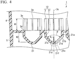
- FIG. 4 is a partial enlarged view of FIG. 2 .
- a culture vessel 1 of Embodiment 1 which will be described using FIGS. 1A to 4 is a vessel for culturing cell aggregates.
- the culture vessel 1 includes a plurality of wells 21 formed in a plate-like body 2 and tubular bodies 3 disposed above the respective wells 21.
- a direction intersecting the plane of the plate-like body 2 at right angles will be referred to as the "vertical direction”
- the tubular body 3 side will be referred to as being “above”
- the well 21 side will be referred to as being "below”.
- the culture vessel 1 of Embodiment 1 includes a side wall 4 which protrudes above openings of a plurality of the wells 21 and surrounds a plurality of the wells 21 and a base 5 which protrudes below the openings of a plurality of the wells 21.
- the shapes of the outer surface and the inner surface of the side wall 4 when the culture vessel 1 is seen in plan view are substantially rectangular respectively.
- the base 5 protrudes further than the wells 21 from the plate-like body 2, and thus, when the culture vessel 1 is placed on a horizontal surface, the end surface of the base 5 comes into contact with the horizontal surface.
- the respective wells 21 have a culture space capable of storing a cell aggregate and culture fluid.
- the tubular body 3 has a substantially cylindrical shape and has an inner cavity communicating with the culture space.
- a plurality of communication portions 3a are formed at equal intervals along the circumferential direction of the tubular body 3.
- the communication portion 3a is a slit which is parallel to a central axis 3c (refer to FIG. 4 ) of the tubular body 3 and is formed from a base end 3d to a front end 3e of the tubular body 3.
- the central axis 3c of the tubular body 3 is parallel to the vertical direction.
- slits are not limited to the above-described example as long as, when the culture vessel 1 is inclined in order to discharge some of the culture fluids, some of the culture fluids in the wells 21 can be appropriately discharged without allowing cell aggregates to exit from the wells 21.
- a slit may be formed toward the front ends 3e of the tubular bodies 3 from above the base ends 3d of the tubular bodies 3.
- a slit may be a through-hole which penetrate the tubular walls of the tubular bodies 3 in the thickness direction thereof and have the longitudinal direction along the circumferential direction of the tubular bodies 3.
- the communication portion 3a is not limited to a slit and may be, for example, a through hole penetrating the tubular walls 3b of the tubular bodies 3 in the thickness direction thereof.
- the number of the communication portions 3a is eight, but there is no particular limitation regarding the number of the communication portions 3a.
- the number of the communication portions is preferably two or more, more preferably four or more, and still more preferably six or more since it is easy to efficiently discharge culture fluids from the respective wells 21 and fresh culture fluids described below are allowed to easily and uniformly move into the respective wells.
- the angle between a pair of the communication portions 3a selected from the two or more communication portions 3a which are separated from each other in the circumferential direction is preferably 90 degrees or more and more preferably 180 degrees or more since culture fluids are efficiently discharged.
- any width W1 (the width in the circumferential direction) of the slit is acceptable as long as the width is smaller than the diameter of the cell aggregate measured by microscopic observation just before the cell aggregate is moved to the culture vessel 1 of Embodiment 1.
- the width is preferably 0.1 mm or larger, more preferably 0.2 mm or larger, and still more preferably 0.25 mm or larger from the viewpoint of improvement in the discharge efficiency of culture fluids, and the width is preferably 0.5 mm or smaller, more preferably 0.4 mm or smaller, and still more preferably 0.3 mm or smaller, in order to reduce the possibility of cell aggregates flowing out.
- the width of the slit refers to the length of the slit in a direction perpendicular to the central axis 3c (refer to FIG. 4 ) of the tubular body 3.
- the width of the slit refers to the length of the slit in a direction parallel to the central axis 3c (refer to FIG. 4 ) of the tubular body 3.
- the liquid surface of culture fluids is preferably placed above the base ends 3d of the tubular bodies 3 in order for the quality of culture fluids in a plurality of the wells 21 to be made uniform by means of diffusion using the communication portions 3a.
- the height H1 of the tubular body 3 is preferably in a range of 1 mm to 7 mm and more preferably in a range of 3 mm to 5 mm so as to prevent cell aggregates from floating on culture fluids, exceeding the front end of the tubular body 3, and moving into a space between the tubular body 3 and the side wall 4, adjacent tubular bodies 3, and adjacent wells 21.
- the openings (apertures) of a plurality of the wells 21 are in the same plane as one surface 2a (refer to FIG. 2 ) of the plate-like body 2 connecting a plurality of the wells 21 together, and the tubular bodies 3 are disposed on the plane.
- the slits which are the communication portion 3a are preferably formed from the base ends 3d (refer to FIG. 4 ) of the tubular bodies 3 from the viewpoint of improvement in the discharge efficiency of culture fluids.
- the central axes 3c of the tubular bodies 3 coincide with the central axes of the wells 21 and the radii of cylindrical surfaces which are the inner circumferential surfaces of the tubular bodies 3 are equal to the radii of the openings of the wells 21.
- the well 21 includes a tubular trunk portion 21 a (refer to FIG.
- the inner surface of the trunk portion 21a is a cylindrical surface
- the central axes 3c of the tubular bodies 3 coincide with the central axes of the wells 21 and the radii of the cylindrical surfaces which are the inner circumferential surfaces of the tubular bodies 3 are equal to the radii of the cylindrical surfaces which are the inner circumferential surfaces of the trunk portions 21 a.
- Each of the wells 21 includes the tubular trunk portion 21 a and a funnel-shaped bottom portion 21b provided at one end of the trunk portion 21 a.
- the culture space in the well 21 contracts toward the front end (opposite to the opening) of the well 21.
- a central portion 21c of the bottom portion is a curved surface. That is, the inner surface of the bottom portion 21b can be an inverted conic surface having a curved surface at the top portion.
- the trunk portion 21 a may have, for example, a substantially cylindrical shape.
- the inner surface of the bottom portion 21b has a substantially V shape and is arcuate in the central portion 21c.
- a continuous portion between the trunk portion 21 a and the bottom portion 21 b in the inner surface is preferably a curved surface.
- the inner surface of the well 21 is substantially parallel to the central axis of the well 21 in the trunk portion 21 a, includes a pair of inclined surfaces 21e inclining toward a central axis passing through a top point 21d (the deepest portion) of the inner surface of the well 21 in the funnel-shaped bottom portion 21b, and includes an arcuate surface 21f in the central portion 21 c of the bottom portion 21b.
- the aperture angle ⁇ of the bottom portion 21 b is preferably greater than 60 degrees and 100 degrees or smaller, more preferably in a range of 70 degrees to 100 degrees, and still more preferably in a range of 80 degrees to 90 degrees since it is possible to efficiently culture cell aggregates.
- the "aperture angle" in the present disclosure refers to the angle formed by the pair of inclined surfaces 21e and is, for example, the angle indicated by ⁇ in FIG. 4 .
- the curvature radius R 1 on the central portion inner surface of the bottom portion 21 b is preferably in a range of 0.5 mm to 2.0 mm since, during the exchange of culture fluids, cell aggregates are not exposed on the surface of culture fluids and stimuli being applied to cell aggregates can be suppressed and is more preferably in a range of 1.0 mm to 2.0 mm since it is easy to observe cell aggregates using an optical microscope.
- the "curvature radius of the central portion inner surface” refers to a radius corresponding to a circumference including a curved surface in which the curvature of the front end portion of the bottom portion 21b of the well 21 is 1/R 1 .
- the curvature radius R 1 of the central portion inner surface can be measured using laser distance meters or by means of actual measurements of cut sections of molded products.
- the length H2 (refer to FIG. 4 ) from one end of both ends of the slit 3a which is closer to the well 21 to a deepest portion 21 d of the well 21 is preferably in a range of 3.0 mm to 6.0 mm since, after some of the culture fluids are removed in order to exchange culture fluids, cell aggregates to which new culture fluids are yet to be added are not exposed on the surface of culture fluids and damage or stimuli being applied to cell aggregates due to the removal of culture fluids are reduced and is more preferably in a range of 3.0 mm to 5.0 mm since, furthermore, a sufficient amount of nutrients and oxygen are supplied to cell aggregates.
- the depth of the well 21 is preferably in a range of 3.0 mm to 6.0 mm since, after some of the culture fluids are removed in order to exchange culture fluids, cell aggregates to which new culture fluids are yet to be added are not exposed on the surface of culture fluids and damage or stimuli being applied to cell aggregates due to the removal of culture fluids are reduced and is more preferably in a range of 3.0 mm to 5.0 mm since, furthermore, a sufficient amount of nutrients and oxygen are supplied to cell aggregates.
- the diameter of the well 21 at the opening is, for example, preferably 4.0 mm or larger since operability is excellent in a case in which multi dispensers are used and is preferably 11.0 mm or smaller since the number of the wells 21 per culture vessel increases.
- the capacity of the structure 12 (refer to FIG 4 ) made up of the wells 21 and the tubular bodies 3 per inside space, in other words, the sum of the capacity of the culture spaces of the wells 21 (the inside spaces of the wells 21) and the capacity of the inside spaces in the inner circumferential surfaces (for example, cylindrical surfaces) of the tubular bodies 3 is not particularly limited, but is, for example, preferably in a range of 50 ⁇ L to 500 ⁇ L since a sufficient amount of culture fluids or reagents can be added in order to culture cell aggregates and is more preferably in a range of 50 ⁇ L to 200 ⁇ L since the amount of culture fluids or reagents being used decreases.
- the form of the well in the culture vessel of the present embodiment is not limited to the well including the trunk portion 21a and the funnel-shaped bottom portion 21b.
- the form of the well may be, for example, a form in which the inner surface has a hemispherical shape or a form in which a trunk portion and a bottom portion are provided and the bottom portion has a hemispherical shape as long as it is possible to discharge some of the culture fluids in wells without allowing cell aggregates to exit from the wells.
- a cell adhesiveness reduction treatment is preferably carried out on at least the inner surface of the bottom portion 21b of the well 21.
- the "cell adhesiveness reduction treatment” refers to a treatment for reducing the adhesiveness of the inner surface of the well 21 to cells. Adhesiveness being reduced means that, for example, it becomes difficult for the inner surface of the well 21 and cells to adhere to each other or the inner surface of the well 21 and cells become incapable of adhering to each other.
- Examples of the cell adhesiveness reduction treatment include hydrophilization treatments on the inner surfaces of the wells 21.
- Examples of the hydrophilization treatments include formation of coating layers using water-soluble resins, formation of coating layers using hydrophilic resins, and the like.
- water-soluble resins refers to resins which are hydrated by means of ionic bonding or hydrogen bonding with water molecules and are thus dissolved in water and have a solubility of 1.0 g or higher in 100 g of water at 25°C.
- examples of the water-soluble resins include resins having a necessary and sufficient amount of ionic or polar side chains with respect to main chains in molecules in order to be dissolved in water.
- water-soluble resins examples include saponified substances of polyvinyl acetates, polyvinylpyrrolidone, polyethylene glycols, polyacrylamides, polymethacrylamides, polyhydroxyethylmethacrylates, polypentaerythritol triacrylates, polypentaerythritol tetraacrylates, polydiethylene glycol diacrylates, copolymers of monomers constituting the above-described water-soluble resins, copolymers between 2-methacryloyloxyethyl phosphorylcholine and other monomers (for example, butyl methacrylates and the like), and the like.
- structures made up of one or more selected from saponified substances of polyvinyl acetates, polyvinylpyrrolidone, and polyethylene glycols and functional groups described below are preferred.
- the above-described structures can suppress stimuli on a variety of cells and improve the growth rates of cell aggregates and the qualities of grown cell aggregates.
- Examples of the saponified substances of polyvinyl acetates include copolymers between polyvinyl alcohols or vinyl alcohols and other compounds, saponified substances between hydrophilic group-modified, hydrophobic group-modified, anionic modified, cationic modified, or amide group-modified vinyl acetates or modified vinyl acetates obtained by modifying reactive groups such as acetoacetyl groups, and the like.
- the average degree of polymerization of polymers is not particularly limited, but is preferably in a range of 100 to 10,000 and more preferably in a range of 200 to 5,000 since it is easy to form uniform membranes on the inner surfaces of culture vessels and workability becomes favorable.
- the degree of saponification of the saponified substances of polyvinyl acetates is not particularly limited, but is preferably in a range of 20 mol% to 100 mol% and more preferably in a range of 50 mol% to 95 mol% of the entire polyvinyl acetates.
- the water-soluble resins are preferably water-soluble resins having functional groups to be cured in side chains.
- the functional groups to be cured include radioactive reactive, photosensitive, and thermal reactive functional groups and the like.
- the photosensitive functional groups include diazo groups, azide groups, cinnamoyl groups, and the like.
- the thermal reactive and radioactive reactive functional groups include vinyl groups, epoxy groups, and the like.
- water-soluble resins having these functional groups water-soluble resins having photosensitive functional groups are preferred since it is possible to rapidly carry out curing treatments and cure the functional groups using simple facilities.
- the water-soluble resins are preferably water-soluble resins having azide groups and more preferably water-soluble resins represented by Formula (Ia) or (Ib) below since it is possible to form uniform coating layers by means of irradiation with light having wavelengths in a range of 300 nm to 500 nm and improve the growth efficiency of cell aggregates by reducing the amount of cells adhered.
- R represents a trivalent hydrocarbon group having a carbonyl group and a -NH- group.
- the hydrocarbon group include saturated hydrocarbon groups and unsaturated hydrocarbon groups, and, among these, groups represented by Formula (II) below are preferred since it becomes easy to synthesize polar side chains.
- R represents a divalent hydrocarbon group having a carbonyl group and a -NH- group.
- hydrocarbon group include saturated hydrocarbon groups and unsaturated hydrocarbon groups.
- r1 represents 1 to 1,000, r2 represents 40 to 4,995, r3 represents 0 to 4,000, and n represents 1, 2, or 3.
- r1 represents 1 to 1,000, r2 represents 40 to 4,995, and r3 represents 0 to 4,000.
- the hydrophilic resins are not particularly limited, and examples thereof include poly-2-hydroxyethyl methacrylate (poly-HEMA), phosphocholine group-containing polymer compounds, polyethylene glycol chain-containing polymer compounds, and the like.
- poly-HEMA poly-2-hydroxyethyl methacrylate
- phosphocholine group-containing polymer compounds polyethylene glycol chain-containing polymer compounds, and the like.
- the thickness of the coating layer is not particularly limited, but is, for example, preferably in a range of 100 nm to 5,000 nm and more preferably in a range of 150 nm to 1,000 nm since it is possible to suppress cells being adhered to the wells through protein by reducing the amount of protein incorporated into the coating layer while reducing physical stimuli received by cells from the base material (the wells).
- Materials for the culture vessel according to the present disclosure are not particularly limited, but are preferably resins since it is possible to make the culture vessel disposable and molding is easy.
- the resins include polyolefin-based resins or cyclic polyolefin-based resins such as polypropylene resins, polyethylene resins, and ethylene-propylene copolymers, polystyrene-based resins such as polystyrene, acrylonitrile-butadiene-styrene-based resins, methacryl-based resins such as polycarbonate resins, polyethylene terephthalate resins, and polymethyl methacrylate resins, fluorine-based resins such as vinyl chloride resins, polybutylene terephthalate resins, polyacrylate resins, polyarylate resins, polysulphone resins, polyether sulphone resins, polyether ether ketone resins, polyether imide resins, and polytetrafluoroethylene, cellulose-based resins such
- Examples of the form of the culture vessel according to the present disclosure include multi-well plates including a plurality of wells and the like.
- the number of wells in the multi-well plate is not particularly limited and is, for example, 6, 12, 24, 48, 96, or 384.
- the culture vessel according to the present disclosure can be manufactured in the following manner.
- the above-described resin material is molded into a desired shape by means of injection molding, blow molding, injection blow molding, or the like.
- a multi-well plate body 11 including the plate-like body 2, a plurality of the wells 21 formed in the plate-like body 2, the side wall 4, and the base 5 and a plurality of the tubular bodies 3 can be molded in the same mold using an injection molding method.
- the cell adhesiveness reduction treatment is carried out on the formed vessel.
- the cell adhesiveness reduction treatment can be carried out using, for example, the method described in WO2013/183777 .
- the vessel is sterilized.
- the sterilization include ethylene oxide gas sterilization, hot air sterilization, irradiation sterilization, and the like, irradiation sterilization using ⁇ rays or electron beams is preferred, and ⁇ ray sterilization is more preferred from the viewpoint of radiotransparency when aggregate production is taken into account.
- the culture method since the culture vessel according to the present disclosure is used, there is little influence on cell aggregates, and culture fluids can be efficiently exchanged with each other, and thus cell aggregates can be efficiently cultured.
- the culture method of the present disclosure includes a culture fluid exchange step of culturing cell aggregate in the well in which the culture spaces are filled with culture fluid for a predetermined time, and thereafter inclining the cell aggregate culture vessel according to the present disclosure, thereby passing some of the culture fluid in the well through the communication portion so as to discharge the culture fluid to the outside of the tubular body, then, removing the culture fluid from the culture vessel, and then adding the same amount or almost the same amount of new culture fluid (fresh culture fluid) as the removed culture fluid to the culture vessel, and the culture fluid exchange step is repeated a predetermined number of times.
- the culture subjects of the culture method of the present disclosure are, for example, cell aggregates of human embryonic stem cells (human ES cells) or human pluripotent stem cells (human iPS cells), it is also possible to, for example, move cell aggregates formed in the multi-well plate for forming cell aggregates to the culture vessel of the present disclosure together with the full amount of culture fluids and apply the culture method of the present disclosure to the cell aggregates.
- human ES cells human embryonic stem cells
- human iPS cells human pluripotent stem cells
- the diameters of cell aggregates which are formed in the multi-well plate for forming cell aggregates and are soon to be moved to the culture vessel of the present disclosure is preferably in a range of 500 ⁇ m to 1,000 ⁇ m since a sufficient amount of nutrients can be supplied to cell aggregates in the culture vessel of the present disclosure.
- Cell aggregates are moved to the culture vessel of the present disclosure so that one cell aggregate is disposed in one well.
- the "predetermined time” may vary depending on the kinds of cells, the capacity of the wells, the purpose of culture, and the like and may vary every culture fluid exchange step.
- the "predetermined time” in the culture fluid exchange step in the beginning of culture may be longer than the "predetermined time” in the culture fluid exchange step performed later than the beginning of the culture.
- the number of times of the culture fluid exchange step is also appropriately determined depending on the kinds of cells, the capacity of the wells, the purpose of the culture, and the like.
- culture fluid exchange step some of the culture fluids in the respective wells are made to pass through the communication portions and are discharged to the outside of the tubular bodies in order to reduce damage or stimuli applied to cell aggregates due to the removal of culture fluids.
- cell aggregates are preferably held in a state in which cell aggregates are all sunk in the culture fluids.
- the culture vessel is preferably shaken so that, after new culture fluids are added to the culture vessel, the fresh culture fluids uniformly move into the respective wells.
- culture fluids that are used in the culture fluid exchange step may be used depending on the kinds of cells, the capacity of the wells, the purpose of culture, and the like.
- culture fluids are preferably supplied not only to the culture spaces in the wells 21 but also to the space which is above the openings of the wells 21 and is surrounded by the side wall 4 since the qualities of culture fluids in a plurality of the wells 21 are made uniform by means of diffusion through the communication portions 3a.
- culture fluids are preferably supplied so that some of the culture fluids spill out of a plurality of the wells 21 and are loaded into even the inner cavities of the tubular bodies 3 on the base end side.
- the liquid surface of the culture fluids may be above one ends of both ends of the slits 3a which are closer to the wells 21.
- Cell aggregates that have been subjected to the cell aggregate culture method in which the culture vessel of the present disclosure is used may be moved to another culture vessel and be further cultured in the culture vessel.
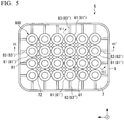
- FIG. 5 is a plan view of a cell aggregate culture vessel 6 of Embodiment 2.
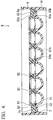
- FIG. 6 is a sectional view in the direction of arrow line VI-VI' in FIG. 5 .
- FIG. 7 is an enlarged end view cut in the direction of arrow line VII-VII' in FIG. 5 .
- FIG. 8 is a plan view of a multi-well plate body 61 constituting the cell aggregate culture vessel 6 of Embodiment 2
- FIG. 9 is a sectional view in the direction of arrow line IX-IX' in FIG. 8 .
- FIG. 10 is a plan view of a liquid flow control body 800 constituting the cell aggregate culture vessel 6 of Embodiment 2
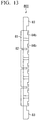
- FIG 11 is a bottom surface view of the liquid flow control body 800 illustrated in FIG. 10 , FIG.
- the culture vessel 6 of Embodiment 2 which will be described using FIGS. 5 to 14 , similar to the culture vessel 1 of Embodiment 1, includes a plurality of wells 71 formed in a plate-like body 7, tubular bodies 81 disposed above the respective wells 71, a side wall 9 which protrudes above the openings of a plurality of the wells 71 and surrounds a plurality of the wells 71, and a base 10 which protrudes below the openings of a plurality of the wells 71.
- the culture vessel 6 of Embodiment 2 is different from the culture vessel 1 of Embodiment 1 because the tubular bodies 81 constitute the liquid flow control body 800 including a connected body 80 (refer to FIGS. 10 and 11 ) of a plurality of the tubular bodies 81 and communication portions 81b are slits in the circumferential directions of the tubular bodies 81.
- a direction intersecting the plane of the plate-like body 7 at right angles will be referred to as the "vertical direction” (Z-axis direction)
- the tubular body 81 side will be referred to as being “above”
- the well 71 side will be referred to as being “below”.
- the central axes 81 a (refer to FIG. 7 ) of the tubular bodies 81 are parallel to the vertical direction and the Z-axis direction and coincide with the central axes of the wells 71.
- the liquid flow control body 800 may not be joined to the multi-well plate body 61 and may be a separate body from the multi-well plate body 61 or may be integrated with the multi-well plate body 61 by means of joining.
- each of the tubular bodies 81 constituting the liquid flow control body 800 at least one groove 84b is formed, a plurality of grooves 84b are preferably formed in the circumferential direction, and a plurality of grooves 84b are more preferably formed in the circumferential direction at equal intervals.
- the grooves 84b constitute communication portions 81b which can discharge culture fluids without allowing the passage of cell aggregates to the outside of the tubular bodies 81, and in end surfaces (bottom surfaces) 84 on the well 71 side of the respective tubular bodies 81, portions 84a in which the grooves 84b are not formed are in contact with one surfaces 7a of the plate-like plate 7 respectively.
- the grooves 84b are formed in the tubular bodies 81 and constitute slits 81 b which are along the circumferential directions of the tubular bodies 81.
- the depth of the groove 84b or the width W2 of the slit (refer to FIG. 7 ) needs to be smaller than the diameter of a cell aggregate, which is soon to be moved to the culture vessel 6 of Embodiment 2, measured by means of microscopic observation, and, in a case in which the diameter of the cell aggregate is in a range of 600 ⁇ m to 700 ⁇ m, the depth or width is preferably 0.1 mm or larger, more preferably 0.2 mm or larger, and still more preferably 0.25 mm or larger from the viewpoint of improvement in the discharge efficiency of culture fluids, and the depth or width is preferably 0.5 mm or smaller, more preferably 0.4 mm or smaller, and still more preferably 0.3 mm or smaller from the viewpoint of reducing the possibility of cell aggregates flowing out.
- the length W3 in the circumferential direction of the groove 84b or the slit is preferably 2 mm or larger from the viewpoint of improvement in the discharge efficiency of culture fluids.
- the number of the communication portions 81b is four, but there is no particular limitation regarding the number of the communication portions 81b.
- the number of the communication portions is preferably two or more and more preferably four or more since it is easy to efficiently discharge culture fluids from the wells 71 and the above-described fresh culture fluids are allowed to easily and uniformly move into the respective wells 71.
- a pair of the communication portions 81 b selected from the two or more communication portions 81b are preferably separated from each other in the circumferential direction at 90 degrees or more.
- the shape of the inner surface of the well 71 is a hemispherical shape; however, in the culture vessel 6 of Embodiment 2, the form of the well 71 is not limited thereto and may be the same form as that of the culture vessels 1 of Embodiment 1.
- the diameter of the well 71 at the opening, the depth of the well 71, the capacity per inside space in a structure made up of the wells 71 and the tubular bodies 81, the capacity of each of the wells 71, and the like are also the same as those in the culture vessels 1 of Embodiment 1.
- the liquid flow control body 800 includes the connected body 80 which is a plurality of the tubular bodies 81 connected together through crosslinking portions 82 and a position-regulating portion 83.
- the connected body 80 which is a plurality of the tubular bodies 81 connected together through crosslinking portions 82 and a position-regulating portion 83.
- a plurality of the tubular bodies 81 are connected to each other through the crosslinking portions 82 disposed between adjacent tubular bodies 81. As illustrated in FIG.
- the end portions (the other end portions) of the position-regulating portions 83 which are away from the tubular bodies 81 are preferably in contact not only with the inner surface 9a of the side wall 9 but also with one surface 7a of the plate-like body 7 since it is easy to determine the position of the liquid flow control body 800 in the multi-well plate body 61.
- the position-regulating portions 83 are connected to, out of a plurality of the tubular bodies 81, all of the tubular bodies 81' disposed at the outer edge of the connected body 80.
- the culture vessel 6 of Embodiment 2 is not limited thereto.
- FIG. 15A is a plan view of a cell aggregate culture vessel 100 of Embodiment 3
- FIG. 15B is a partial enlarged view of FIG. 15A
- FIG. 16 is an enlarged sectional view in the direction of arrow line XVI-XVI' in FIG. 15A
- FIG. 17A is a sectional view in the direction of arrow line XVII-XVII' in FIG. 15A
- FIG. 17B is a partial enlarged view of FIG. 17A
- FIG. 18 is a partial enlarged view of FIG. 16
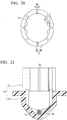
- FIG. 19 is a perspective sectional view for describing an internal structure of the structure 12 made up of the tubular body 3 and the well 21 of the cell aggregate culture vessel 100.
- FIG. 19 is a perspective sectional view for describing an internal structure of the structure 12 made up of the tubular body 3 and the well 21 of the cell aggregate culture vessel 100.
- FIG. 20 is a partial enlarged view of FIG. 15A
- FIG. 21 is a conceptual view for describing a state after a cell aggregate 14 is cultured in a culture fluid 13 for a predetermined time using the cell aggregate culture vessel 100 of the present disclosure and then some of the culture fluid 13 in the well 21 is discharged to the outside of the structure 12 through the communication portion 3a.
- the culture vessel 100 of Embodiment 3 which will be described using FIGS. 15A to 21 is a vessel for culturing cell aggregates and has the same constitution as those of the above-described cell aggregate culture vessels of Embodiment 1 and Embodiment 2 except for the fact that liquid guide portions described below are provided.
- the culture vessel 100 includes a plurality of the wells 21 formed in the plate-like body 2 and the tubular bodies 3 disposed above the respective wells 21.
- a direction intersecting the plane of the plate-like body 2 at right angles will be referred to as the "vertical direction”
- the tubular body 3 side will be referred to as being "above”
- the well 21 side will be referred to as being "below”.
- the culture vessel 100 of Embodiment 3 includes the side wall 4 which protrudes above the openings of a plurality of the wells 21 and surrounds a plurality of the wells 21 and the base 5 which protrudes below the openings of a plurality of the wells 21.
- the shapes of the outer surface and the inner surface of the side wall 4 when the culture vessel 100 is seen in plan view are substantially rectangular respectively.
- the base 5 protrudes further than the wells 21 from the plate-like body 2, and thus, when the culture vessel 1 is placed on a horizontal surface, the end surface of the base 5 comes into contact with the horizontal surface.
- the respective wells 21 have a culture space capable of storing cell aggregates and culture fluids.
- the tubular body 3 has a substantially cylindrical shape and has an inner cavity communicating with the culture space.
- a plurality of the communication portions 3a are formed at equal intervals along the circumferential direction of the tubular body 3.
- the communication portion 3a is a slit which is parallel to the central axis 3c (refer to FIG. 18 ) of the tubular body 3 and is formed from the base end 3d to the front end 3e of the tubular body 3.
- the central axis 3c of the tubular body 3 is parallel to the vertical direction and coincides with the central axes of the wells 21 and the structure 12 (refer to FIGS. 17A, 17B , 18, 19 , 21 , and the like) made up of the tubular bodies 3 and the wells 21.
- the number of the communication portions 3a is eight, but there is no particular limitation regarding the number of the communication portions 3a.
- the number of the communication portions is preferably two or more, more preferably four or more, and still more preferably six or more since the properties of culture fluids being discharged from the respective wells 21 are improved, and fresh culture fluids described below are allowed to easily and uniformly move into the respective wells.
- the width W1 (the width in the circumferential direction) of the slit needs to be smaller than the diameter of a cell aggregate, which is soon to be moved to the culture vessel, measured by means of microscopic observation, and, in a case in which the diameter of the cell aggregate is in a range of 600 ⁇ m to 700 ⁇ m, the width is preferably 0.1 mm or larger, more preferably 0.2 mm or larger, and still more preferably 0.25 mm or larger from the viewpoint of improvement in the properties of culture fluids being discharged and the properties of fresh culture fluids flowing into the wells, and the width is preferably 0.5 mm or smaller, more preferably 0.4 mm or smaller, and still more preferably 0.3 mm or smaller from the viewpoint of reducing the possibility of cell aggregates flowing out.
- tubular body 3 is preferably in a range of 1 mm to 7 mm and more preferably in a range of 3 mm to 5 mm so as to prevent cell aggregates from floating on culture fluids, exceeding the front end of the tubular body 3, and moving into a space between the tubular body 3 and an adjacent tubular body 3, adjacent tubular bodies 3, and adjacent wells 21.
- the openings of a plurality of the wells 21 are in the same plane as one surface 2a (refer to FIGS. 16 to 18 ) of the plate-like body 2 connecting a plurality of the wells 21 together, and the tubular bodies 3 are disposed on the surface 2a, but the slits which are the communication portion 3a are preferably formed from the base ends 3d (refer to FIGS. 18 and 19 ) of the tubular bodies 3 from the viewpoint of improvement in the properties of culture fluids being discharged.
- the structure 12 (refer to FIGS. 17A, 17B , and 18 ) made up of the tubular bodies 3 and the wells 21, and specifically, it is preferable that the central axes 3c of the tubular bodies 3 coincide with the central axes of the wells 21 and the radii of cylindrical surfaces which are the inner circumferential surfaces of the tubular bodies 3 are equal to the radii of the openings of the wells 21.
- the well 21 includes a tubular trunk portion 21a (refer to FIG. 18 ) and the inner surface of the trunk portion 21 a is a cylindrical surface
- the central axes 3c of the tubular bodies 3 coincide with the central axes of the wells 21 and the radii of the cylindrical surfaces which are the inner circumferential surfaces of the tubular bodies 3 are equal to the radii of the cylindrical surfaces which are the inner circumferential surfaces of the trunk portions 21 a.
- each of the wells 21 includes the tubular trunk portion 21a and the funnel-shaped bottom portion 21 b provided at one end of the trunk portion 21 a.
- the culture space in the well 21 contracts toward the front end (opposite to the opening) of the well 21.
- the central portion 21c of the bottom portion 21 b is a curved surface. That is, the inner surface of the bottom portion 21b can be an inverted conic surface having a curved surface at the top portion.
- the trunk portion 21 a may have, for example, a substantially cylindrical shape.
- the inner surface of the well 21 is substantially parallel to the central axis of the well 21 in the trunk portion 21a, includes a pair of the inclined surfaces 21 e inclining toward the central axis passing through the top point 21d (the deepest portion) of the inner surface of the well 21 from the lower end side of the inner surface of the trunk portion 21 a in the funnel-shaped bottom portion 21 b, and includes an arcuate surface 21 f in the central portion 21c of the bottom portion 21b.
- the aperture angle ⁇ of the bottom portion 21b is preferably greater than 60 degrees and 100 degrees or smaller, more preferably in a range of 70 degrees to 100 degrees, and still more preferably in a range of 80 degrees to 90 degrees since it is possible to efficiently culture cell aggregates.
- the "aperture angle" in the present disclosure refers to the angle formed by the pair of inclined surfaces 21 e and is, for example, the angle indicated by ⁇ in FIG. 18 .
- the length H2 in a case in which the structure 12 (refer to FIG. 18 ) made up of the wells 21 and the tubular bodies 3 is cut on a plane including the central axis thereof and is seen in plan view, the length H2 (refer to FIG.
- the depth of the well 21 is preferably in a range of 3.0 mm to 6.0 mm since, after some of the culture fluids are removed in order to exchange culture fluids, cell aggregates to which new culture fluids are yet to be added are not exposed on the surface of culture fluids and damage or stimuli being applied to cell aggregates due to the removal of culture fluids are reduced and is more preferably in a range of 3.0 mm to 5.0 mm since, furthermore, a sufficient amount of nutrients and oxygen are supplied to cell aggregates.
- the diameter of the well 21 at the opening is, for example, preferably 4.0 mm or larger since operability is excellent in a case in which multi dispensers are used and is preferably 11.0 mm or smaller since the number of the wells 21 per culture vessel increases.
- the capacity of the structure 12 made up of the wells 21 and the tubular bodies 3 per inside space, in other words, the sum of the capacity of the culture spaces of the wells 21 (the inside spaces of the wells 21) and the capacity of the inside spaces in the inner circumferential surfaces (for example, cylindrical surfaces) of the tubular bodies 3 is not particularly limited, but is, for example, preferably in a range of 50 ⁇ L to 500 ⁇ L since a sufficient amount of culture fluids or reagents can be added in order to culture cell aggregates and is more preferably in a range of 50 ⁇ L to 200 ⁇ L since the amount of culture fluids or reagents being used decreases.
- the upper side end portion 610a of each of the protrusion portions 610 and the lower side end portions 31b of the slits 3a are disposed at the same positions in the vertical direction.
- the liquid guide assisting grooves 620 are provided in the culture vessel 100, it is assumed that the properties of fresh culture fluids from the slits 3a flowing into the wells 21 and the properties of culture fluids in the wells 21 being discharged to the outside of the structure 12 are improved due to the capillary action.
- the side closer to the top point 21 d (refer to FIG.
- lower side end portions 610b of the respective protrusion portions 610 reach the bottom surface (the inner surface of the bottom portion 21b of the well 21) in the inner surface of the well 21.
- One terminating end 620a of the liquid guide assisting groove 620 formed between a pair of the protrusion portions 610 is a closed end and is regulated by the inner surface of the bottom portion 21 b of the well 21.
- the inner surface of the bottom portion 21 b of the well 21 defining the terminating end 620a is a part of the inclined surface 21e (refer to FIG. 18 ) inclining downwards from the upstream side to the downstream side of the flow of culture fluids capable of flowing into the culture space in the well 21 from the slit 3a.
- the liquid guide assisting grooves 620 accelerate culture fluids to be discharged to the outside of the structure 12 through the slits 3a and to flow into the structure 12.
- the length W4 (refer to FIG. 16 ) in the vertical direction from the upper side end surface 611 of the protrusion portion 610 to a lower side end 311 of the slit 3a is preferably 0.1 mm or larger and more preferably 0.3 mm or larger since it is easy to improve the properties of fresh culture fluids from the slits 3a flowing into the wells 21.
- the protrusion portions 610 may be formed so as to reach the upper ends of the tubular bodies 3. Furthermore, in the culture vessel 100 illustrated in FIGS.
- the slits 3a are formed from the base ends 3d (refer to FIGS. 18 and 19 ) to the front ends 3e of the tubular bodies 3, and thus W4 is equal to the lengths in the vertical direction of the portions formed on the inner surfaces of the tubular bodies 3 in the protrusion portions 610.
- the slits 3a are not necessarily formed from the base ends 3d of the tubular bodies 3, and, in a case in which the slits 3a are formed from above the base ends 3d of the tubular bodies 3, W4 is shorter than the lengths in the vertical direction of the portions formed on the inner surfaces of the tubular bodies 3 in the protrusion portions 610.
- the length W4 is defined as the maximum length of lengths from the upper side end surfaces 611 of the respective protrusion portions 610 to the lower side ends of the slits 3a.
- the distance W5 (refer to FIG. 17B ) between the protrusion portions 610 on the circumference passing through the lower side ends 311 of the slits 3a is preferably 0.3 mm or larger and more preferably 0.4 mm or larger and is preferably 1.0 mm or smaller and more preferably 0.7 mm or smaller since it is easy to improve the properties of fresh culture fluids from the slits 3a flowing into the wells 21 and the properties of culture fluids in the wells 21 being discharged to the outside of the structure 12, and it is possible to prevent cell aggregates from being sandwiched between a pair of the protrusion portions 610.
- the circumference passing through the lower side ends 311 of the slits 3a refers to a circumference having the center at a point which is on the central axis 3c (refer to FIG. 18 ) of the tubular body 3 and is on a plane including the lower side ends 311 of the slits 3a and intersecting the central axis 3c at right angles.
- W5 can be the distance between the protrusion portions 610 at the same position as that of the lower side end 311 of the slit 3a on the inner surface of the tubular body 3.
- a surface 610c of each of the protrusion portions 610 which faces the culture space is a convex surface protruding toward the extended axis (the central axis of the well 21) of the central axis 3c of the tubular body 3.
- the convex surface is a curved surface which is higher in a portion further from the inner surface 21e (the inner surface of the trunk portion 21 a) of the well 21 than in a portion close thereto.
- the tubular body 3 at right angles is, for example, an arch (a shape formed when a circle is divided into two parts using a single string) surrounded by an arc and a straight line.
- the section has a shape regulated by an overlapping portion of two circles.
- the section of the protrusion portion has a shape regulated by an overlapping portion of two circles and the curvature radius R 2 (refer to FIG. 20 ) of the circumference which forms the arch or the shape regulated by an overlapping portion of two circles and includes an arc protruding toward the central axis of the tubular body is 0.5 mm or larger and 1.0 mm or smaller.
- the cell adhesiveness reduction treatment is preferably carried out on the inner surface of at least the bottom portion 21 b (refer to FIG. 18 ) of the well 21.
- the numbers of the pairs of the protrusion portions 610 and the liquid guide assisting grooves 620 are respectively two in a single structure 12; however, in the culture vessel 100 of the present disclosure, the numbers of the pairs of the protrusion portions 610 and the liquid guide assisting grooves 620 are not limited thereto.
- the numbers of the pairs of the protrusion portions 610 and the liquid guide assisting grooves 620 provided may be one or more in consideration of the discharge amount of culture fluids in the wells 21 in accordance with the capacity of the wells 21 and the amount of culture fluids flowing into the wells 21.
- the communication portions 3a capable of discharging culture fluids in the wells 21 to the outside of the tubular bodies 3 are slits which are formed in the tubular walls 3b of the tubular bodies 3 and are parallel to the central axes 3c (refer to FIG. 18 ) of the tubular bodies 3, but the communication portions 3a are not limited thereto.
- the communication portions may be slits which penetrate the tubular walls 3b of the tubular bodies 3 in the thickness directions and have the longitudinal directions along the circumferential directions of the tubular bodies 3.
- the communication portions 3a are not limited to slits and may be, for example, through-holes which penetrate the tubular walls 3b of the tubular bodies 3 in the thickness directions.
- the shape of the inner surface of the well 21 is a shape including the trunk portion 21a and the bottom portion 21b; however, in the culture vessel 10 of Embodiment 2, the form of the well 21 is not limited thereto and may be a hemispherical shape.
- the culture vessel 100 of Embodiment 3 described using FIGS. 15A to 21 can be manufactured using the same method as for the culture vessel 1 of Embodiment 1.
- a multi-well plate body 110 (refer to FIG. 17A ) including the plate-like body 2, a plurality of the wells 21 formed in the plate-like body 2, the protrusion portions 610, the side wall 4, and the base 5 can be molded in the same mold using an injection molding method.
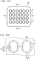
- FIG. 22A is a plan view of a cell aggregate culture vessel 200 of Embodiment 4, and FIG. 22B is a partial enlarged view of FIG. 22A .
- FIG. 23 is an enlarged sectional view in the direction of arrow line XXIII-XXIII' in FIG. 22A .
- FIG. 24A is an enlarged sectional view in the direction of arrow line XXIV-XXIV' in FIG. 22A
- FIG. 24B is a partial enlarged view of FIG. 24A .
- FIG. 25 is a partial enlarged view of FIG. 23
- FIG. 26 is a perspective sectional view for describing an internal structure of the structure 12 made up of the tubular bodies 3 and the wells 21 of the cell aggregate culture vessel 200.
- FIG. 27 is a conceptual view for describing a state after the cell aggregate 14 is cultured in the culture fluid 13 for a predetermined time using the cell aggregate culture vessel 200 of the present disclosure and then some of the culture fluid in the wells 21 is discharged.
- the culture vessel 200 of Embodiment 4 which will be described using FIGS. 22A to 27 has the same constitution as that of the cell aggregate culture vessel 100 of Embodiment 3 except for the fact that the form of the liquid guide portion is different.
- the liquid guide assisting groove 720 is provided by forming a pair of the protrusion portions 710 on the inner surface of the structure 12 so that upper side end surfaces 711 of the respective protrusion portions 710 are disposed above the lower side ends 311 of the slits 3a and forming the protrusion portions 710 along the same direction as the longitudinal direction of the respective slits 3a on both sides of at least one slit 3a in the width direction in the inner surface of the structure 12 made up of the tubular bodies 3 and the wells 21.
- upper side end portions 710a of the respective protrusion portions 710 and the lower side end portions 31 b of the slits 3a are disposed at the same positions in the vertical direction.
- the liquid guide portion 70 includes a base portion 730 connecting the lower side end portions 710b of the respective protrusion portions 710 together. Since the base portion 730 is disposed between the bottom surface of the well 21 and a pair of the protrusion portions 710 so as to connect the lower side end portions 710b of the respective protrusion portions 710 together, the base portion 730 has a surface 730a defining one terminating end (closed end) of the liquid guide assisting groove 720.
- the inclination angle ⁇ (refer to FIG. 25 ) of the surface 730a defining one terminating end (closed end) of the liquid guide assisting groove 720 with respect to the plane intersecting the central axis 3c (refer to Fig. 25 ) of the tubular body 3 at right angles is preferably 0 degrees or more and more preferably 30 degrees or more since the inflow of culture fluids becomes favorable and is preferably 75 degrees or less and more preferably 60 degrees or less since excessive discharge of culture fluids is suppressed.
- the communication portions 3a capable of discharging culture fluids in the wells 21 to the outside of the tubular bodies 3 are slits which are formed in the tubular walls 3b of the tubular bodies 3 and are parallel to the central axes of the tubular bodies 3; however, in the present disclosure, the communication portions 3a are not limited to slits, and, for example, the communication portions may be through-holes which penetrate the tubular walls of the tubular bodies in the thickness directions.
- the number of the communication portions 3a, the width W1 of the communication portion 3a, the form of the communication portion 3a, the height H1 of the tubular body 3, the form of the well 21, the depth H2 of the well 21, the capacity of the structure 12, the number of the pairs of the protrusion portions 710, the distance W4 in the vertical direction from the upper side end surface 711 of the protrusion portion 710 to the lower side end 311 of the communication portion 3a, the distance W5 between the protrusion portions 710, the sectional shape of the protrusion portion 710 cut on a surface in a direction intersecting the central axis 3c of the tubular body 3 at right angles, and the like are the same as those in the culture vessel 100 of Embodiment 3.
- the cell adhesiveness reduction treatment is preferably carried out at least on the inner surface of the bottom portion
- the cell aggregate culture vessel of the present embodiment may be constituted of a multi-well plate body and a liquid flow control body.
- the cell aggregate culture vessel similar to the cell aggregate culture vessel of Embodiment 2, can be manufactured by separately molding the multi-well plate body and the liquid flow control body respectively, and, for example, joining these components or disposing the liquid flow control body in the multi-well plate body.
- a 24-well multi-well plate (horizontal side: 65.0 mm, vertical side: 50.0 mm, height: 20.5 mm) was molded using a polystyrene resin (manufactured by PS Japan Corporation, trade name: HF77) by means of injection molding.
- a culture vessel in the present example was provided with a shape illustrated in FIGS. 1A to 3
- wells were provided with a shape illustrated in FIG. 4
- the aperture angle ( ⁇ in FIG. 4 ) of the bottom surface was set to 85 degrees
- the curvature radius R 1 of the inner surface in the bottom portion central portion was set to 2.0 mm.
- a plasma treatment (oxygen plasma, 10 minutes) was carried out on the 24-well multi-well plate to which the obtained tubular bodies were attached using a plasma treatment device (manufactured by Branson/IPC, SERIES 7000). Therefore, wettability was imparted to the plate surface as a pretreatment.
- the plate was repeatedly washed three times using ultrapure water, was dried, and then was irradiated with ⁇ rays at an absorbed dose of 10 kGy (a device manufactured by Radia Industry Co., Ltd.), thereby obtaining a culture vessel of Example 1.
- a cell suspension obtained by dispersing HepG2 in a culture fluid (Dulbecco's modified MEM+10% by volume of fetal bovine serum) at a concentration of 3 ⁇ 10 4 cells/mL was prepared, was dispensed in a PrimeSurface (registered trademark) 96V plate (Sumitomo Bakelite Co., Ltd., MS-9096V) so that each well contained 100 ⁇ L, and was cultured in a carbon dioxide culture vessel including 5% carbon dioxide and having a humidity of 99% and a temperature of 37°C. It was confirmed using a microscope that one cell aggregate (spheroid) having a diameter of approximately 700 ⁇ m was formed in each well after six days.
- a culture fluid Dulbecco's modified MEM+10% by volume of fetal bovine serum
- Example 1 the culture vessel of Example 1 was inclined in a variety of directions, some of the culture fluid in the respective wells was collected at the corners of the culture vessel, approximately 3 mL of the culture fluid was suctioned using an aspiration pipette, and then approximately 3 mL of a new culture fluid (fresh culture fluid) was put into the culture vessel of Example 1. Afterwards, culture fluids were exchanged with each other every three days by means of the same operation. During the exchange of culture fluids, attention was paid to prevent the cell aggregates from being dried. After the exchange operation of culture fluids was carried out five times, and cell aggregates in the respective wells were observed using a microscope. As a result, it was found that cell aggregates in all the wells smoothly grew, and the diameters of cell aggregates were 1,100 ⁇ m on average.
- Example 2 According to the [formation of cell aggregates (spheroids) for which human hepatocellular carcinoma cells (HepG2) were used] of Example 1, 96 cell aggregates (spheroids) having a diameter of approximately 700 ⁇ m were formed. Next, cell aggregates in the respective wells were collected together with a culture fluid in the same manner as in Example 1 and were moved into four PrimaSuface 60 mm Schales (MS-9060X, Sumitomo Bakelite Co., Ltd.) (24 cell aggregates per plate). After the cell aggregates (spheroids) in all the 96 wells were moved to the Schales, 1.84 mL of a new culture fluid was added to each Schale, thereby setting the amount of the culture fluid in the Schale to 4 mL.
- MS-9060X Sumitomo Bakelite Co., Ltd.
- Example 1 had little influence on cell aggregates and was capable of efficiently exchanging culture fluids and smoothly growing all of the 96 cell aggregates.
- the culture vessel of Comparative Example 1 due to the erroneous suction of cell aggregates or the joining between cell aggregates, it was not possible to smoothly grow all of the 96 cell aggregates.
- the diameter was set to 6.2 mm, and the depth was set to 5.0 mm, and the depth of the trunk portion was set to 2.6 mm.
- the inner diameter was set to 6.2 mm
- the height was set to 5.0 mm
- the thickness of the side wall was set to 0.8 mm
- the capacity of a structure made up of the wells and the tubular bodies per inside space was set to approximately 250 ⁇ L
- the capacity of a portion below the lower side ends of the slits in the structure that is, the capacity of each of the wells was set to approximately 105 ⁇ L.
- communication portions in which the width W1 (refer to FIG.
- a plasma treatment (oxygen plasma, 10 minutes) was carried out on the 24-well multi-well plate to which the obtained tubular bodies were attached using a plasma treatment device (manufactured by Branson/IPC, SERIES 7000). Therefore, wettability was imparted to the plate surface as a pretreatment.
- a culture vessel of Example 3 was produced in the same manner as in Example 2 except for the fact that the inclination angle ⁇ was set to 0 degrees.
- a culture vessel of Example 4 was produced in the same manner as in Example 2 except for the fact that H3 was set to 1.0 mm.
- a culture vessel of Example 5 was produced in the same manner as in Example 2 except for the fact that the inclination angle ⁇ was set to 0 degrees, and H3 was set to 0.5 mm.
- a 24-well multi-well plate (horizontal side: 65.0 mm, vertical side: 50.0 mm, height: 20.5 mm) was molded using a polystyrene resin (manufactured by PS Japan Corporation, trade name: HF77) by means of injection molding.
- a culture vessel in the present example was provided with a shape illustrated in FIGS. 15A to 21
- wells were provided with a shape illustrated in FIG. 18
- the aperture angle ( ⁇ in FIG. 18 ) of the bottom surface was set to 85 degrees
- the curvature radius R 1 of the inner surface in the bottom portion central portion was set to 2.0 mm.
- the diameter was set to 6.2 mm, and the depth was set to 5.0 mm, and the depth of the trunk portion was set to 2.6 mm.
- the inner diameter was set to 6.2 mm
- the height was set to 5.0 mm
- the thickness of the side wall was set to 0.8 mm
- the capacity of a structure made up of the wells and the tubular bodies per inside space was set to approximately 250 ⁇ L
- the capacity of a portion below the lower side ends of the slits in the structure that is, the capacity of each of the wells was set to approximately 105 ⁇ L.
- communication portions in which the width W1 (refer to FIG.
- the properties of culture fluids being discharged and flowing in were evaluated according to the following methods. First, 6 mL of a culture fluid was added to the inside of the culture vessel placed on a horizontal surface, and the amount of the entire culture fluid in the culture vessel was set to 6 mL.
- the culture vessel was inclined 20 degrees for five seconds so that the culture fluid was discharged through the slits having the protrusion portions of the liquid guide portions provided on both sides, some of the culture fluid in the respective wells was collected at the corners of the culture vessel, immediately, approximately 5 mL or more (5.2 mL to 5.9 mL) of the culture fluid was suctioned using an aspiration pipette, and the inclination of the culture vessel was returned to zero degrees after the suction. After that, the amount of the culture vessel remaining in the respective wells was collected and measured using a micro pipette, the property of the culture fluid being discharged was evaluated on the basis of the following "evaluation standard 1", and the results are shown in Table 1.
- the culture fluid flows into the wells, the culture fluid surface in the culture vessel was above the lower side ends of the slits, and the culture fluid surface in the structure made up of the wells and the tubular bodies is present on the same plane as the culture fluid surface in portions other than the structure.
- the culture fluid does not flow into the wells, the culture fluid surface in the wells was below the lower side ends of the slits, and the culture fluid surface is lower in the structure made up of the wells and the tubular bodies than in portions other than the structure.
- the present invention can also be carried out in forms other than what has been described above within the scope of the gist of the present invention.
- Embodiments disclosed in the present application are examples, and the present invention is not limited thereto.
- the scope of the present disclosure is preferentially interpreted on the basis of the description of the accompanying claims rather than the description of the above-described specification, and all modifications within ranges equivalent to the claims are considered to be within the claims.
Landscapes
- Health & Medical Sciences (AREA)
- Chemical & Material Sciences (AREA)
- Engineering & Computer Science (AREA)
- Life Sciences & Earth Sciences (AREA)
- Organic Chemistry (AREA)
- Wood Science & Technology (AREA)
- Zoology (AREA)
- Bioinformatics & Cheminformatics (AREA)
- Biomedical Technology (AREA)
- Biotechnology (AREA)
- Genetics & Genomics (AREA)
- General Health & Medical Sciences (AREA)
- Biochemistry (AREA)
- General Engineering & Computer Science (AREA)
- Microbiology (AREA)
- Clinical Laboratory Science (AREA)
- Sustainable Development (AREA)
- Chemical Kinetics & Catalysis (AREA)
- Medicinal Chemistry (AREA)
- Immunology (AREA)
- Materials Engineering (AREA)
- Cell Biology (AREA)
- Polymers & Plastics (AREA)
- Analytical Chemistry (AREA)
- Hematology (AREA)
- Tropical Medicine & Parasitology (AREA)
- Virology (AREA)
- Oncology (AREA)
- Gastroenterology & Hepatology (AREA)
- Apparatus Associated With Microorganisms And Enzymes (AREA)
- Micro-Organisms Or Cultivation Processes Thereof (AREA)
Abstract
Description
- The present disclosure relates to a cell aggregate culture vessel and a cell aggregate culture method using the same. Priority is claimed on Japanese Patent Application No.
2014-106450, filed May 22, 2014 2014-218661, filed October 27, 2014 - Embryonic stem cells (ES cells) have multilineage potential and can differentiate into a variety of tissue cells. Therefore, a variety of studies have been carried out relating to the application of embryonic stem cells in the field of so-called regenerative medicine, in which cells lost due to disease, accidents, or the like are repaired and tissues are restored (for example, PTL 1).
- ES cells have great diversity and can differentiate into a variety of cells. An example of a method for differentiating ES cells into a variety of cells is the formation of cell aggregates known as embryonic bodies (EB). These cell aggregates are formed by floating a culture of ES cells, iPS cells, and the like, and, when the ES cells are cultured for approximately two weeks in a state in which cell aggregates are formed, differentiation into a variety of cell types is observed. Therefore, the formation of embryonic bodies is used as one of the standard methods for investigating the pluripotent differentiation of cells.
- Among the methods for culturing ES cells in a floating state, the most widely used method is hanging drop culture. Hanging drop culture is a method in which cells are cultured in culture fluids suspended in a water droplet shape. However, this method has problems of a low success rate of formation of embryonic bodies, incapability of microscopic observation, troublesome operations, and the like. In order to solve these problems, for example, culture vessels having water-insoluble cured membranes formed on the vessel inner surfaces by curing water-soluble resin membranes have been proposed (for example, PTL 2).
- When clinical application is considered, research and development using human ES cells becomes necessary, but human ES cells have problems of a higher possibility of cell death and a greater difficulty in obtaining embryonic bodies compared with mouse ES cells. In order to solve these problems, for example, culture vessels have been proposed in which funnel shapes having an aperture angle in a range of 60 degrees to 100 degrees are provided as the well bottom portions and the center portions have concave roundness (for example, PTL 3). For research and development using human iPS cells as well, the same culture vessels have been proposed.
- PTL 1 (Japanese Unexamined Patent Application, First Publication No.
2008-99662 2008-178367 WO2013/183777 ) are incorporated into the present specification by reference. -
- [PTL 1] Japanese Unexamined Patent Application, First Publication No.
2008-99662 - [PTL 2] Japanese Unexamined Patent Application, First Publication No.
2008-178367 - [PTL 3]
WO2013/183777 - [NPL 1] Cell Stem Cell, Vol. 10, No. 6, pp. 771 to 785 (2012)
- There are cases in which cell aggregates formed using the above-described culture vessels are moved to Schale or the like for additional culture (NPL 1). Generally, waste products such as uric acid or carbon dioxide discharged from cells make culture fluids acidic, and thus culture fluids in Schale need to be exchanged periodically. However, when Schale is shaken due to such periodic exchange of culture fluids, there is a concern that cell aggregates may accumulate in the center portion of the Schale and come into contact and fuse with each other, and thus, the cell aggregates may become too large or may have distorted shapes, oxygen or nutrients may not be sufficiently supplied to cells constituting the cell aggregates, and the cells may die. In addition, even normal cells are damaged due to enzymes and the like released from the dead cells. Therefore, in culturing, it is important to grow cell aggregates up to appropriate diameters and exchange culture fluids while causing minimal damage or exposure to stimuli in order to obtain high-quality cell aggregates through culture. In addition, since stem cells, for example, human embryonic stem cells (human ES cells) or human pluripotent stem cells (human iPS cells), have a favorable metabolism, the exchange frequency of culture fluids is higher than that in other cells. Therefore, particularly for these cells, efficient exchange of culture fluids is desired.
- In one or a plurality of embodiments, the present disclosure provides a culture vessel which has little influence on cell aggregates and is capable of efficiently exchanging culture fluids, and a cell aggregate culture method using the same.
- In one or a plurality of embodiments, the present disclosure relates to a vessel for culturing cell aggregates. The cell aggregate culture vessel includes a well having a culture space capable of storing the cell aggregates and culture fluids and a tubular body having an inner cavity communicating with the culture space, and one or more communication portion capable of discharging the culture fluids without allowing passage of the cell aggregates to the outside of the tubular body are formed in a tubular wall of the tubular body.
- In one or a plurality of embodiments, the present disclosure is a culture method for culturing cell aggregates using the cell aggregate culture vessel of the present disclosure. The cell aggregate culture method includes a step of culturing the cell aggregates in the well in which the culture space is filled with culture fluids, and thereafter inclining the cell aggregate culture vessel, thereby passing some of the culture fluids in the well through the communication portion and discharging the culture fluids to the outside of the tubular body.
- According to the cell aggregate culture vessel and the cell aggregate culture method of the present disclosure, there is little influence on cell aggregates, and culture fluids can be efficiently exchanged with each other.
-
-
FIG. 1A is a plan view of a cell aggregate culture vessel ofEmbodiment 1. -
FIG. 1B is a partial enlarged view ofFIG. 1A . -
FIG. 2 is a sectional view in the direction of arrow line II-II' inFIG. 1A . -
FIG. 3 is a sectional view in the direction of arrow line III-III' inFIG. 1A . -
FIG. 4 is a partial enlarged view ofFIG. 2 . -
FIG. 5 is a plan view of a cell aggregate culture vessel ofEmbodiment 2. -
FIG. 6 is an enlarged sectional view in the direction of arrow line VI-VI' inFIG. 5 . -
FIG. 7 is an enlarged end view cut in the direction of arrow line VII-VII' inFIG. 5 . -
FIG. 8 is a plan view of a multi-well plate body constituting the cell aggregate culture vessel ofEmbodiment 2. -
FIG. 9 is a sectional view in the direction of arrow line IX-IX' inFIG. 8 .FIG. 10 is a plan view of a liquid flow control body constituting the cell aggregate culture vessel ofEmbodiment 2. -
FIG. 11 is a bottom surface view of the liquid flow control body illustrated inFIG. 10 . -
FIG. 12 is an enlarged sectional view in the direction of arrow line XII-XII' inFIG. 10 . -
FIG. 13 is an enlarged side view of the liquid flow control body illustrated inFIG. 10 . -
FIG. 14 is an enlarged perspective view of the liquid flow control body illustrated inFIG. 11 . -
FIG. 15A is a plan view of a cell aggregate culture vessel ofEmbodiment 3. -
FIG. 15B is a partial enlarged view ofFIG. 15A . -
FIG. 16 is an enlarged sectional view in the direction of arrow line XVI-XVI' inFIG. 15A . -
FIG. 17A is an enlarged sectional view in the direction of arrow line XVII-XVII' inFIG. 15A . -
FIG. 17B is a partial enlarged view ofFIG. 17A . -
FIG. 18 is a partial enlarged view ofFIG. 16 . -
FIG. 19 is a perspective sectional view for describing an internal structure of a structure made up of a tubular body and a well of the cell aggregate culture vessel illustrated inFIG 15A . -
FIG. 20 is a partial enlarged view ofFIG. 15A . -
FIG. 21 is a conceptual view for describing a state after a cell aggregate is cultured in a culture fluid for a predetermined time using the cell aggregate culture vessel illustrated inFIG. 15A and then some of the culture fluid in the well is discharged. -
FIG. 22A is a plan view of a cell aggregate culture vessel ofEmbodiment 4. -
FIG. 22B is a partial enlarged view ofFIG. 22A . -
FIG. 23 is an enlarged sectional view in the direction of arrow line XXIII-XXIII' inFIG. 22A . -
FIG. 24A is an enlarged sectional view in the direction of arrow line XXIV-XXIV' inFIG. 22A . -
FIG. 24B is a partial enlarged view ofFIG. 24A . -
FIG. 25 is a partial enlarged view ofFIG. 23 . -
FIG. 26 is a perspective sectional view for describing an internal structure of a structure made up of a tubular body and a well of the cell aggregate culture vessel illustrated inFIG. 22A . -
FIG. 27 is a conceptual view for describing a state after cell aggregates are cultured in a culture fluid for a predetermined time using the cell aggregate culture vessel illustrated inFIG. 22A and then some of the culture fluid in the well is discharged. - A cell aggregate culture vessel of the present disclosure (hereinafter, in some cases, also abbreviated as the "culture vessel") has inner cavities communicating with culture spaces in wells and includes a tubular body in which one or more communication portion capable of discharging culture fluids without allowing passage of cell aggregates to the outside are formed in a tubular wall thereof. Therefore, with a simple operation of inclining the culture vessel, it is possible to discharge culture fluids in a plurality of the wells from the culture space within a short period of time. When culture fluids are discharged using the above-described method, compared with the methods described in the related art, culture fluids can be efficiently exchanged with each other without adversely affecting cell aggregates. Since culture fluids in a plurality of the wells can be discharged from the culture spaces, automatic exchange of culture fluids using machines can also be expected.
- Among cells, stem cells such as human embryonic stem cells (human ES cells) or human pluripotent stem cells (human iPS cells) have favorable metabolism and have a possibility of being differentiated due to slight stimuli. Therefore, the culture vessel of the present disclosure capable of efficiently exchanging culture fluids while suppressing the influence of damage, stimuli, and the like on cell aggregates is suitable for culture of cell aggregates of these stem cells.
- The present disclosure relates to the following one or a plurality of embodiments.
- (1) A cell aggregate culture vessel for culturing a cell aggregate, including: a well having a culture space capable of storing the cell aggregate and culture fluid and a tubular body which is disposed on the well on a plane at which the well has an opening and has an inner cavity communicating with the culture space, in which one or more communication portion capable of discharging the culture fluid without allowing passage of the cell aggregate to the outside of the tubular body is formed in a tubular wall of the tubular body.
- (2) The cell aggregate culture vessel according to (1), in which a plurality of the communication portions are formed in the tubular body.
- (3) The cell aggregate culture vessel according to (1) or (2), in which the communication portion is a slit parallel to a central axis of the tubular body.
- (4) The cell aggregate culture vessel according to (1) or (2), in which the communication portion is a slit along a circumferential direction of the tubular body.
- (5) The cell aggregate culture vessel according to (3) or (4), in which widths of the slit is 0.1 mm or larger and 0.5 mm or smaller.
- (6) The cell aggregate culture vessel according to any one of (3) to (5), in which, in a case in which a structure made up of the well and the tubular body is cut on a plane including a central axis thereof and is seen in plan view, a length from one of both ends of the slit which is closer to the well to the deepest portion of the well is 3.0 mm or larger and 6.0 mm or smaller.
- (7) The cell aggregate culture vessel according to any one of (1) to (6), in which the cell aggregate culture vessel includes a multi-well plate body including a plurality of the wells, and a plurality of the tubular bodies are disposed on the well on the plane at which the wells of the multi-well plate have openings.
- (8) The cell aggregate culture vessel according to (7), in which the communication portion is a slit which is parallel to the central axes of the tubular body and are formed from base end of the tubular body.
- (9) The cell aggregate culture vessel according to (7) or (8), in which the multi-well plate body and the plurality of tubular bodies are molded in the same mold.
- (10) The cell aggregate culture vessel according to any one of (1) to (6), in which the cell aggregate culture vessel includes a multiwell plate body including a plurality of the wells and a side wall which protrudes above the opening of the well so as to surround the plurality of wells and has a substantially rectangular shape when seen in plan view and a liquid flow control body disposed in a space surrounded by the side wall of the multi-well plate, the liquid flow control body includes the plurality of tubular bodies, a plurality of crosslinking portions which are disposed so as not to come into contact with a surface of the multi-well plate body which has the opening of the well and connect the plurality of tubular bodies so as to form a connected body of the plurality of tubular bodies, and at least a pair of position-regulating portions having one end portion connected to the connected body and the other end portion coming into contact with the side wall, and one position-regulating portion comes into contact with one of the inner surfaces of the side wall which face each other, and the other position-regulating portion comes into contact with the other of the inner surfaces of the side wall which face each other.
- (11) The cell aggregate culture vessel according to (10), in which the liquid flow control body is a separate body from the multi-well plate body.
- (12) The cell aggregate culture vessel according to any one of (1) to (11), further including: a liquid guide portion, in which the liquid guide portion includes a pair of protrusion portions disposed on an inner surface of the structure made up of the well and the tubular body, the protrusion portions form a liquid guide assisting groove, and upper side end surfaces of the protrusion portions are disposed above lower side end of the communication portion.
- (13) The cell aggregate culture vessel according to (12), in which surfaces of the protrusion portions facing the culture space are curved surfaces protruding toward the central axes of the tubular body.
- (14) The cell aggregate culture vessel according to (12) or (13), in which a length from the upper side end surfaces of the protrusion portions to the lower side end of the communication portion is 0.1 mm or larger.
- (15) The cell aggregate culture vessel according to any one of (12) to (14), in which a distance between a pair of the protrusion portions on a circumference passing through the lower side end of the communication portion is 0.3 mm or larger and 1.0 mm or smaller.
- (16) The cell aggregate culture vessel according to any one of (12) to (15), in which lower side end portions of the protrusion portions reach a bottom surface in the inner surface of the well.
- (17) The cell aggregate culture vessel according to any one of (12) to (16), in which the liquid guide portion connects the lower side end portions of a pair of the protrusion portions together and further includes a base portion including a surface defining one terminating end of the liquid guide assisting groove.
- (18) The cell aggregate culture vessel according to (17), in which the surface defining one terminating end of the liquid guide assisting groove is an inclined surface inclining from a downstream side to an upstream side of a flow of the culture fluid capable of flowing from the communication portion into the culture space.
- (19) The cell aggregate culture vessel according to any one of (12) to (18), in which closed end of the liquid guide assisting groove is disposed above a bottom portion of the well.
- (20) The cell aggregate culture vessel according to any one of (1) to (19), in which at least an inner surface of the bottom portion of the well is coated with a coating layer formed of a water-soluble resin represented by Formula (Ia) or (Ib) below.


- (21) The cell aggregate culture vessel according to any one of (1) to (20), in which the well has a tubular trunk portion and a funnel-shaped bottom portion provided at one end of the trunk portion, a central portion of the bottom portion is a concave surface, an aperture angle of the bottom portion is in a range of 60 degrees to 100 degrees, and a curvature radius of the concave surface of the bottom portion is in a range of 0.5 mm to 2.0 mm.
- (22) The cell aggregate culture vessel according to any one of (1) to (21), in which the cell aggregate is stem cells.
- (23) The cell aggregate culture vessel according to (22), in which the stem cells are human embryonic stem cells (human ES cells) or human pluripotent stem cells (human iPS cells).
- (24) A cell aggregate culture method for culturing a cell aggregate using the cell aggregate culture vessel according to any one of (1) to (23), including a step of culturing the cell aggregate in the well in which the culture space is filled with culture fluid, and thereafter inclining the cell aggregate culture vessel, thereby passing some of the culture fluid in the well through the communication portion and discharging the culture fluid to the outside of the tubular body.
-
- [1] A cell aggregate culture vessel for culturing cell aggregates, including: a well having a culture space capable of storing the cell aggregates and culture fluids, a tubular body having an inner cavity communicating with the culture space, and a liquid guide portion, in which one or more communication portion capable of discharging the culture fluids without allowing passage of the cell aggregates to the outside of the tubular body is formed in a tubular wall of the tubular body, the liquid guide portion including a liquid guide assisting groove, provided by forming a pair of protrusion portions on an inner surface of a structure made up of the well and the tubular body, and disposing an upper side end surface of each of the protrusion portions above lower side end of the communication portion, and forming one of the protrusion portion at each of both sides of at least one communication portion on an inner surface of the tubular portion.
- [2] The cell aggregate culture vessel according to [1], in which the communication portion is a slit parallel to a central axis of the tubular body.
- [3] The cell aggregate culture vessel according to [2], in which the slit is formed from a base end of the tubular body.
- [4] The cell aggregate culture vessel according to [2] or [3], in which widths of the slit is 0.1 mm or larger and 0.5 mm or smaller.
- [5] The cell aggregate culture vessel according to any one of [1] to [4], in which surfaces of the respective protrusion portions which face the culture space are curved surfaces protruding toward the central axis of the tubular body.
- [6] The cell aggregate culture vessel according to any one of [1] to [5], in which a length from upper side end surfaces of the protrusion portions to lower side end of the communication portion is 0.1 mm or larger.
- [7] The cell aggregate culture vessel according to any one of [1] to [6], in which a distance between the protrusion portions on a circumference passing through the lower side end of the communication portion is 0.3 mm or larger and 1.0 mm or smaller.
- [8] The cell aggregate culture vessel according to any one of [1] to [7], in which lower side end portions of the respective protrusion portions reach a bottom surface in the inner surface of the well.
- [9] The cell aggregate culture vessel according to any one of [1] to [7], in which the liquid guide portion connects the lower side end portions of the respective protrusion portions together and further includes a base portion including a surface defining one terminating end of the liquid guide assisting groove.
- [10] The cell aggregate culture vessel according to [9], in which the surface defining one terminating end of the liquid guide assisting groove is an inclined surface inclining from a downstream side to an upstream side of a flow of the culture fluid capable of flowing from the communication portion into the culture space.
- [11] The cell aggregate culture vessel according to any one of [1] to [10], in which, in a case in which the structure made up of the well and the tubular body is cut on a plane including a central axis thereof and is seen in plan view, a length from the lower side end of the communication portion to the deepest portion of the well is 3.0 mm or larger and 6.0 mm or smaller.
- [12] The cell aggregate culture vessel according to any one of [1] to [11], in which the well has a tubular trunk portion and a funnel-shaped bottom portion provided at one end of the trunk portion, a central portion of the bottom portion is a concave surface, an aperture angle of the bottom portion is in a range of 60 degrees to 100 degrees, and a curvature radius of the concave surface of the bottom portion is in a range of 0.5 mm to 2.0 mm.
- [13] The cell aggregate culture vessel according to [12], in which a closed end of the liquid guide assisting groove is disposed above the bottom portion of the well.
- [14] The cell aggregate culture vessel according to any one of [1] to [13], in which the cell aggregate culture vessel includes a multi-well plate body including a plurality of the wells, and a plurality of the tubular bodies are disposed on a surface of the multi-well plate which has the openings of the wells.
- [15] The cell aggregate culture vessel according to [14], in which the multi-well plate body and the plurality of tubular bodies are molded in the same mold.
- [16] The cell aggregate culture vessel according to [12] or [13], in which at least an inner surface of the bottom portion of the well is coated with a coating layer formed of a water-soluble resin represented by Formula (Ia) or (Ib) below.


- [17] The cell aggregate culture vessel according to any one of [1] to [16], in which the cell aggregates are stem cells.
- [18] The cell aggregate culture vessel according to [17], in which the stem cells are human embryonic stem cells (human ES cells) or human pluripotent stem cells (human iPS cells).
- [19] A cell aggregate culture method for culturing cell aggregates using the cell aggregate culture vessel according to any one of [1] to [18], including a step of culturing the cell aggregates in the well in which the culture space is filled with culture fluids, and thereafter inclining the cell aggregate culture vessel, thereby passing some of the culture fluids in the well through the communication portion and discharging the culture fluids to the outside of the tubular body.
- Hereinafter, embodiments of the present invention will be described in detail with reference to the accompanying drawings. In the drawings, the same or similar portions will be assigned the same or corresponding reference signs and will not be described again. Dimensional ratios in the respective drawings are, in some cases, exaggerated for description in some portions and do not necessarily coincide with actual dimensional ratios.
-
FIG. 1A is a plan view of a cell aggregate culture vessel ofEmbodiment 1, andFIG. 1B is a partial enlarged view ofFIG. 1A .FIG. 2 is a sectional view in the direction of arrow line II-II' inFIG. 1A ,FIG. 3 is a sectional view in the direction of arrow line III-III' inFIG. 1A , andFIG. 4 is a partial enlarged view ofFIG. 2 . - A
culture vessel 1 ofEmbodiment 1 which will be described usingFIGS. 1A to 4 is a vessel for culturing cell aggregates. Theculture vessel 1 includes a plurality ofwells 21 formed in a plate-like body 2 andtubular bodies 3 disposed above therespective wells 21. For convenience, a direction intersecting the plane of the plate-like body 2 at right angles will be referred to as the "vertical direction", thetubular body 3 side will be referred to as being "above", and the well 21 side will be referred to as being "below". - The
culture vessel 1 ofEmbodiment 1 includes aside wall 4 which protrudes above openings of a plurality of thewells 21 and surrounds a plurality of thewells 21 and abase 5 which protrudes below the openings of a plurality of thewells 21. The shapes of the outer surface and the inner surface of theside wall 4 when theculture vessel 1 is seen in plan view are substantially rectangular respectively. Thebase 5 protrudes further than thewells 21 from the plate-like body 2, and thus, when theculture vessel 1 is placed on a horizontal surface, the end surface of thebase 5 comes into contact with the horizontal surface. - The
respective wells 21 have a culture space capable of storing a cell aggregate and culture fluid. Thetubular body 3 has a substantially cylindrical shape and has an inner cavity communicating with the culture space. In atubular wall 3b of thetubular body 3, a plurality ofcommunication portions 3a are formed at equal intervals along the circumferential direction of thetubular body 3. Thecommunication portion 3a is a slit which is parallel to acentral axis 3c (refer toFIG. 4 ) of thetubular body 3 and is formed from abase end 3d to afront end 3e of thetubular body 3. Furthermore, thecentral axis 3c of thetubular body 3 is parallel to the vertical direction. - In an example of the
culture vessel 1 ofEmbodiment 1 which will be described usingFIGS. 1A to 4 , one end of both ends of theslit 3a which is closer to the well 21 coincides with thebase end 3d of thetubular body 3, and the other end further from the well 21 coincides with thefront end 3e of thetubular body 3. However, slits are not limited to the above-described example as long as, when theculture vessel 1 is inclined in order to discharge some of the culture fluids, some of the culture fluids in thewells 21 can be appropriately discharged without allowing cell aggregates to exit from thewells 21. For example, a slit may be formed toward the front ends 3e of thetubular bodies 3 from above the base ends 3d of thetubular bodies 3. Alternatively, a slit may be a through-hole which penetrate the tubular walls of thetubular bodies 3 in the thickness direction thereof and have the longitudinal direction along the circumferential direction of thetubular bodies 3. Alternatively, thecommunication portion 3a is not limited to a slit and may be, for example, a through hole penetrating thetubular walls 3b of thetubular bodies 3 in the thickness direction thereof. - In an example of the
culture vessel 1 ofEmbodiment 1 which will be described usingFIGS. 1A to 4 , the number of thecommunication portions 3a (slits) is eight, but there is no particular limitation regarding the number of thecommunication portions 3a. However, the number of the communication portions is preferably two or more, more preferably four or more, and still more preferably six or more since it is easy to efficiently discharge culture fluids from therespective wells 21 and fresh culture fluids described below are allowed to easily and uniformly move into the respective wells. In addition, in a case in which each of thewells 21 includes two ormore communication portions 3a, the angle between a pair of thecommunication portions 3a selected from the two ormore communication portions 3a which are separated from each other in the circumferential direction is preferably 90 degrees or more and more preferably 180 degrees or more since culture fluids are efficiently discharged. - As illustrated in
FIG. 1B , any width W1 (the width in the circumferential direction) of the slit is acceptable as long as the width is smaller than the diameter of the cell aggregate measured by microscopic observation just before the cell aggregate is moved to theculture vessel 1 ofEmbodiment 1. When the diameter of the cell aggregate is in a range of 600 µm to 700 µm, the width is preferably 0.1 mm or larger, more preferably 0.2 mm or larger, and still more preferably 0.25 mm or larger from the viewpoint of improvement in the discharge efficiency of culture fluids, and the width is preferably 0.5 mm or smaller, more preferably 0.4 mm or smaller, and still more preferably 0.3 mm or smaller, in order to reduce the possibility of cell aggregates flowing out. - In the present specification, in a case in which the longitudinal direction of the slit is parallel to the
central axis 3c (refer toFIG. 4 ) of thetubular body 3, the width of the slit refers to the length of the slit in a direction perpendicular to thecentral axis 3c (refer toFIG. 4 ) of thetubular body 3. In addition, in a case in which the longitudinal direction of the slit is along the circumferential direction of thetubular body 3, the width of the slit refers to the length of the slit in a direction parallel to thecentral axis 3c (refer toFIG. 4 ) of thetubular body 3. - In a cell aggregate culture method of the present disclosure described below, the liquid surface of culture fluids is preferably placed above the base ends 3d of the
tubular bodies 3 in order for the quality of culture fluids in a plurality of thewells 21 to be made uniform by means of diffusion using thecommunication portions 3a. In the culture method, the height H1 of thetubular body 3 is preferably in a range of 1 mm to 7 mm and more preferably in a range of 3 mm to 5 mm so as to prevent cell aggregates from floating on culture fluids, exceeding the front end of thetubular body 3, and moving into a space between thetubular body 3 and theside wall 4, adjacenttubular bodies 3, andadjacent wells 21. - The openings (apertures) of a plurality of the
wells 21 are in the same plane as onesurface 2a (refer toFIG. 2 ) of the plate-like body 2 connecting a plurality of thewells 21 together, and thetubular bodies 3 are disposed on the plane. The slits which are thecommunication portion 3a are preferably formed from the base ends 3d (refer toFIG. 4 ) of thetubular bodies 3 from the viewpoint of improvement in the discharge efficiency of culture fluids. - In order to suppress physical stimuli from being applied to cell aggregates in the middle of the discharging of culture fluids, it is preferable that there are no levels on the inner surface of a structure 12 (refer to
FIGS. 3 and4 ) made up of thetubular bodies 3 and thewells 21, and specifically, it is preferable that thecentral axes 3c of thetubular bodies 3 coincide with the central axes of thewells 21 and the radii of cylindrical surfaces which are the inner circumferential surfaces of thetubular bodies 3 are equal to the radii of the openings of thewells 21. In addition, in a case in which, for example, the well 21 includes atubular trunk portion 21 a (refer toFIG. 4 ) and the inner surface of thetrunk portion 21a is a cylindrical surface, it is preferable that thecentral axes 3c of thetubular bodies 3 coincide with the central axes of thewells 21 and the radii of the cylindrical surfaces which are the inner circumferential surfaces of thetubular bodies 3 are equal to the radii of the cylindrical surfaces which are the inner circumferential surfaces of thetrunk portions 21 a. - Each of the
wells 21 includes thetubular trunk portion 21 a and a funnel-shapedbottom portion 21b provided at one end of thetrunk portion 21 a. In thebottom portion 21b, the culture space in the well 21 contracts toward the front end (opposite to the opening) of the well 21. In the inner surface facing the culture space in the well 21, acentral portion 21c of the bottom portion is a curved surface. That is, the inner surface of thebottom portion 21b can be an inverted conic surface having a curved surface at the top portion. Thetrunk portion 21 a may have, for example, a substantially cylindrical shape. In one or a plurality of embodiments of each of thewells 21, in a sectional view (refer toFIG. 4 ) of the well 21 cut on a plane including the central axis thereof, the inner surface of thebottom portion 21b has a substantially V shape and is arcuate in thecentral portion 21c. In one or a plurality of embodiments of each of thewells 21, a continuous portion between thetrunk portion 21 a and thebottom portion 21 b in the inner surface is preferably a curved surface. - In addition, in one or a plurality of embodiments, in a case in which the
well 21 is cut on a plane including the central axis thereof and is seen in plan view, the inner surface of the well 21 is substantially parallel to the central axis of the well 21 in thetrunk portion 21 a, includes a pair ofinclined surfaces 21e inclining toward a central axis passing through atop point 21d (the deepest portion) of the inner surface of the well 21 in the funnel-shapedbottom portion 21b, and includes anarcuate surface 21f in thecentral portion 21 c of thebottom portion 21b. - As illustrated in
FIG. 4 , the aperture angle θ of thebottom portion 21 b is preferably greater than 60 degrees and 100 degrees or smaller, more preferably in a range of 70 degrees to 100 degrees, and still more preferably in a range of 80 degrees to 90 degrees since it is possible to efficiently culture cell aggregates. The "aperture angle" in the present disclosure refers to the angle formed by the pair ofinclined surfaces 21e and is, for example, the angle indicated by θ inFIG. 4 . - The curvature radius R1 on the central portion inner surface of the
bottom portion 21 b is preferably in a range of 0.5 mm to 2.0 mm since, during the exchange of culture fluids, cell aggregates are not exposed on the surface of culture fluids and stimuli being applied to cell aggregates can be suppressed and is more preferably in a range of 1.0 mm to 2.0 mm since it is easy to observe cell aggregates using an optical microscope. Furthermore, in the present specification, the "curvature radius of the central portion inner surface" refers to a radius corresponding to a circumference including a curved surface in which the curvature of the front end portion of thebottom portion 21b of the well 21 is 1/R1. The curvature radius R1 of the central portion inner surface can be measured using laser distance meters or by means of actual measurements of cut sections of molded products. - In a case in which the structure 12 (refer to
FIG. 4 ) made up of thewells 21 and thetubular bodies 3 is cut on a plane including the central axis thereof and is seen in plan view, the length H2 (refer toFIG. 4 ) from one end of both ends of theslit 3a which is closer to the well 21 to adeepest portion 21 d of the well 21 is preferably in a range of 3.0 mm to 6.0 mm since, after some of the culture fluids are removed in order to exchange culture fluids, cell aggregates to which new culture fluids are yet to be added are not exposed on the surface of culture fluids and damage or stimuli being applied to cell aggregates due to the removal of culture fluids are reduced and is more preferably in a range of 3.0 mm to 5.0 mm since, furthermore, a sufficient amount of nutrients and oxygen are supplied to cell aggregates. - In a case in which the
slit 3a is formed toward thefront end 3e of thetubular body 3 from thebase end 3d of thetubular body 3, the depth of the well 21 is preferably in a range of 3.0 mm to 6.0 mm since, after some of the culture fluids are removed in order to exchange culture fluids, cell aggregates to which new culture fluids are yet to be added are not exposed on the surface of culture fluids and damage or stimuli being applied to cell aggregates due to the removal of culture fluids are reduced and is more preferably in a range of 3.0 mm to 5.0 mm since, furthermore, a sufficient amount of nutrients and oxygen are supplied to cell aggregates. - The diameter of the well 21 at the opening is, for example, preferably 4.0 mm or larger since operability is excellent in a case in which multi dispensers are used and is preferably 11.0 mm or smaller since the number of the
wells 21 per culture vessel increases. - The capacity of the structure 12 (refer to
FIG 4 ) made up of thewells 21 and thetubular bodies 3 per inside space, in other words, the sum of the capacity of the culture spaces of the wells 21 (the inside spaces of the wells 21) and the capacity of the inside spaces in the inner circumferential surfaces (for example, cylindrical surfaces) of thetubular bodies 3 is not particularly limited, but is, for example, preferably in a range of 50 µL to 500 µL since a sufficient amount of culture fluids or reagents can be added in order to culture cell aggregates and is more preferably in a range of 50 µL to 200 µL since the amount of culture fluids or reagents being used decreases. - Furthermore, the form of the well in the culture vessel of the present embodiment is not limited to the well including the
trunk portion 21a and the funnel-shapedbottom portion 21b. The form of the well may be, for example, a form in which the inner surface has a hemispherical shape or a form in which a trunk portion and a bottom portion are provided and the bottom portion has a hemispherical shape as long as it is possible to discharge some of the culture fluids in wells without allowing cell aggregates to exit from the wells. - In one or a plurality of embodiments, a cell adhesiveness reduction treatment is preferably carried out on at least the inner surface of the
bottom portion 21b of the well 21. In the present disclosure, the "cell adhesiveness reduction treatment" refers to a treatment for reducing the adhesiveness of the inner surface of the well 21 to cells. Adhesiveness being reduced means that, for example, it becomes difficult for the inner surface of the well 21 and cells to adhere to each other or the inner surface of the well 21 and cells become incapable of adhering to each other. - Examples of the cell adhesiveness reduction treatment include hydrophilization treatments on the inner surfaces of the
wells 21. Examples of the hydrophilization treatments include formation of coating layers using water-soluble resins, formation of coating layers using hydrophilic resins, and the like. In the present disclosure, "water-soluble resins" refers to resins which are hydrated by means of ionic bonding or hydrogen bonding with water molecules and are thus dissolved in water and have a solubility of 1.0 g or higher in 100 g of water at 25°C. In addition, examples of the water-soluble resins include resins having a necessary and sufficient amount of ionic or polar side chains with respect to main chains in molecules in order to be dissolved in water. - Examples of the water-soluble resins include saponified substances of polyvinyl acetates, polyvinylpyrrolidone, polyethylene glycols, polyacrylamides, polymethacrylamides, polyhydroxyethylmethacrylates, polypentaerythritol triacrylates, polypentaerythritol tetraacrylates, polydiethylene glycol diacrylates, copolymers of monomers constituting the above-described water-soluble resins, copolymers between 2-methacryloyloxyethyl phosphorylcholine and other monomers (for example, butyl methacrylates and the like), and the like. Among these, structures made up of one or more selected from saponified substances of polyvinyl acetates, polyvinylpyrrolidone, and polyethylene glycols and functional groups described below are preferred. The above-described structures can suppress stimuli on a variety of cells and improve the growth rates of cell aggregates and the qualities of grown cell aggregates.
- Examples of the saponified substances of polyvinyl acetates include copolymers between polyvinyl alcohols or vinyl alcohols and other compounds, saponified substances between hydrophilic group-modified, hydrophobic group-modified, anionic modified, cationic modified, or amide group-modified vinyl acetates or modified vinyl acetates obtained by modifying reactive groups such as acetoacetyl groups, and the like. The average degree of polymerization of polymers is not particularly limited, but is preferably in a range of 100 to 10,000 and more preferably in a range of 200 to 5,000 since it is easy to form uniform membranes on the inner surfaces of culture vessels and workability becomes favorable. The degree of saponification of the saponified substances of polyvinyl acetates is not particularly limited, but is preferably in a range of 20 mol% to 100 mol% and more preferably in a range of 50 mol% to 95 mol% of the entire polyvinyl acetates.
- The water-soluble resins are preferably water-soluble resins having functional groups to be cured in side chains. Examples of the functional groups to be cured include radioactive reactive, photosensitive, and thermal reactive functional groups and the like. Examples of the photosensitive functional groups include diazo groups, azide groups, cinnamoyl groups, and the like. Examples of the thermal reactive and radioactive reactive functional groups include vinyl groups, epoxy groups, and the like. Among water-soluble resins having these functional groups, water-soluble resins having photosensitive functional groups are preferred since it is possible to rapidly carry out curing treatments and cure the functional groups using simple facilities.
- The water-soluble resins are preferably water-soluble resins having azide groups and more preferably water-soluble resins represented by Formula (Ia) or (Ib) below since it is possible to form uniform coating layers by means of irradiation with light having wavelengths in a range of 300 nm to 500 nm and improve the growth efficiency of cell aggregates by reducing the amount of cells adhered.


- In Formula (Ia), R represents a trivalent hydrocarbon group having a carbonyl group and a -NH- group. Examples of the hydrocarbon group include saturated hydrocarbon groups and unsaturated hydrocarbon groups, and, among these, groups represented by Formula (II) below are preferred since it becomes easy to synthesize polar side chains.

- In Formula (Ib), R represents a divalent hydrocarbon group having a carbonyl group and a -NH- group. Examples of the hydrocarbon group include saturated hydrocarbon groups and unsaturated hydrocarbon groups.
- In Formula (Ia), r1 represents 1 to 1,000, r2 represents 40 to 4,995, r3 represents 0 to 4,000, and n represents 1, 2, or 3. In Formula (Ib), r1 represents 1 to 1,000, r2 represents 40 to 4,995, and r3 represents 0 to 4,000.
- The hydrophilic resins are not particularly limited, and examples thereof include poly-2-hydroxyethyl methacrylate (poly-HEMA), phosphocholine group-containing polymer compounds, polyethylene glycol chain-containing polymer compounds, and the like.
- The thickness of the coating layer is not particularly limited, but is, for example, preferably in a range of 100 nm to 5,000 nm and more preferably in a range of 150 nm to 1,000 nm since it is possible to suppress cells being adhered to the wells through protein by reducing the amount of protein incorporated into the coating layer while reducing physical stimuli received by cells from the base material (the wells).
- Materials for the culture vessel according to the present disclosure are not particularly limited, but are preferably resins since it is possible to make the culture vessel disposable and molding is easy. Examples of the resins include polyolefin-based resins or cyclic polyolefin-based resins such as polypropylene resins, polyethylene resins, and ethylene-propylene copolymers, polystyrene-based resins such as polystyrene, acrylonitrile-butadiene-styrene-based resins, methacryl-based resins such as polycarbonate resins, polyethylene terephthalate resins, and polymethyl methacrylate resins, fluorine-based resins such as vinyl chloride resins, polybutylene terephthalate resins, polyacrylate resins, polyarylate resins, polysulphone resins, polyether sulphone resins, polyether ether ketone resins, polyether imide resins, and polytetrafluoroethylene, cellulose-based resins such as propionate resins, and the like. Among these, polystyrene resins are preferred from the viewpoint of moldability and sterilizing properties, which are required in culture vessels.
- Examples of the form of the culture vessel according to the present disclosure include multi-well plates including a plurality of wells and the like. The number of wells in the multi-well plate is not particularly limited and is, for example, 6, 12, 24, 48, 96, or 384.
- The culture vessel according to the present disclosure can be manufactured in the following manner.
- First, the above-described resin material is molded into a desired shape by means of injection molding, blow molding, injection blow molding, or the like. In the
culture vessel 1 ofEmbodiment 1 which is shown usingFIGS. 1A to 4 , amulti-well plate body 11 including the plate-like body 2, a plurality of thewells 21 formed in the plate-like body 2, theside wall 4, and thebase 5 and a plurality of thetubular bodies 3 can be molded in the same mold using an injection molding method. - Next, the cell adhesiveness reduction treatment is carried out on the formed vessel. The cell adhesiveness reduction treatment can be carried out using, for example, the method described in
WO2013/183777 . - After the above-described cell adhesiveness reduction treatment, the vessel is sterilized. Examples of the sterilization include ethylene oxide gas sterilization, hot air sterilization, irradiation sterilization, and the like, irradiation sterilization using γ rays or electron beams is preferred, and γ ray sterilization is more preferred from the viewpoint of radiotransparency when aggregate production is taken into account.
- Next, a method for culturing cell aggregates using the culture vessel of the present disclosure will be described. According to the cell aggregate culture method according to the present disclosure (hereinafter, in some cases, also abbreviated as the "culture method"), since the culture vessel according to the present disclosure is used, there is little influence on cell aggregates, and culture fluids can be efficiently exchanged with each other, and thus cell aggregates can be efficiently cultured.
- In one or a plurality of embodiments, the culture method of the present disclosure includes a culture fluid exchange step of culturing cell aggregate in the well in which the culture spaces are filled with culture fluid for a predetermined time, and thereafter inclining the cell aggregate culture vessel according to the present disclosure, thereby passing some of the culture fluid in the well through the communication portion so as to discharge the culture fluid to the outside of the tubular body, then, removing the culture fluid from the culture vessel, and then adding the same amount or almost the same amount of new culture fluid (fresh culture fluid) as the removed culture fluid to the culture vessel, and the culture fluid exchange step is repeated a predetermined number of times.
- In a case in which the culture subjects of the culture method of the present disclosure are, for example, cell aggregates of human embryonic stem cells (human ES cells) or human pluripotent stem cells (human iPS cells), it is also possible to, for example, move cell aggregates formed in the multi-well plate for forming cell aggregates to the culture vessel of the present disclosure together with the full amount of culture fluids and apply the culture method of the present disclosure to the cell aggregates. The diameters of cell aggregates which are formed in the multi-well plate for forming cell aggregates and are soon to be moved to the culture vessel of the present disclosure (that is, cell aggregates which become the subject of culture using the culture vessel of the present disclosure) observed by means of microscopic observation is preferably in a range of 500 µm to 1,000 µm since a sufficient amount of nutrients can be supplied to cell aggregates in the culture vessel of the present disclosure. Cell aggregates are moved to the culture vessel of the present disclosure so that one cell aggregate is disposed in one well.
- In the culture fluid exchange step, the "predetermined time" may vary depending on the kinds of cells, the capacity of the wells, the purpose of culture, and the like and may vary every culture fluid exchange step. For example, the "predetermined time" in the culture fluid exchange step in the beginning of culture may be longer than the "predetermined time" in the culture fluid exchange step performed later than the beginning of the culture. In addition, the number of times of the culture fluid exchange step is also appropriately determined depending on the kinds of cells, the capacity of the wells, the purpose of the culture, and the like.
- In the culture fluid exchange step, some of the culture fluids in the respective wells are made to pass through the communication portions and are discharged to the outside of the tubular bodies in order to reduce damage or stimuli applied to cell aggregates due to the removal of culture fluids. After some of the culture fluids are removed and before new culture fluids are added, cell aggregates are preferably held in a state in which cell aggregates are all sunk in the culture fluids.
- In the culture fluid exchange step, the amount of culture fluids being removed from the culture vessel and the amount of new culture fluids being added are preferably in a range of 50 parts by aggregate to 99 parts by aggregate and more preferably in a range of 75 parts by aggregate to 99 parts by aggregate when the amount of culture fluids in the culture vessel which are soon to be removed is considered as 100 parts by aggregate since cell aggregates are not exposed on the surface of culture fluids and a sufficient amount of nutrients and oxygen are supplied to cell aggregates due to the addition of fresh culture fluids.
- In the culture fluid exchange step, the culture vessel is preferably shaken so that, after new culture fluids are added to the culture vessel, the fresh culture fluids uniformly move into the respective wells.
- As culture fluids that are used in the culture fluid exchange step, culture fluids that have been thus far well-known may be used depending on the kinds of cells, the capacity of the wells, the purpose of culture, and the like.
- In the culture method of the present disclosure, as long as cell aggregates do not excessively float and thus exit from the
wells 21, culture fluids are preferably supplied not only to the culture spaces in thewells 21 but also to the space which is above the openings of thewells 21 and is surrounded by theside wall 4 since the qualities of culture fluids in a plurality of thewells 21 are made uniform by means of diffusion through thecommunication portions 3a. In other words, culture fluids are preferably supplied so that some of the culture fluids spill out of a plurality of thewells 21 and are loaded into even the inner cavities of thetubular bodies 3 on the base end side. The liquid surface of the culture fluids may be above one ends of both ends of theslits 3a which are closer to thewells 21. - Cell aggregates that have been subjected to the cell aggregate culture method in which the culture vessel of the present disclosure is used may be moved to another culture vessel and be further cultured in the culture vessel.
-
FIG. 5 is a plan view of a cellaggregate culture vessel 6 ofEmbodiment 2.FIG. 6 is a sectional view in the direction of arrow line VI-VI' inFIG. 5 .FIG. 7 is an enlarged end view cut in the direction of arrow line VII-VII' inFIG. 5 .FIG. 8 is a plan view of amulti-well plate body 61 constituting the cellaggregate culture vessel 6 ofEmbodiment 2, andFIG. 9 is a sectional view in the direction of arrow line IX-IX' inFIG. 8 .FIG. 10 is a plan view of a liquidflow control body 800 constituting the cellaggregate culture vessel 6 ofEmbodiment 2,FIG 11 is a bottom surface view of the liquidflow control body 800 illustrated inFIG. 10 ,FIG. 12 is an enlarged sectional view in the direction of arrow line XII-XII' inFIG. 10 ,FIG. 13 is an enlarged side view ofFIG. 10 , andFIG 14 is an enlarged perspective view of the liquidflow control body 800 illustrated inFIG. 11 . - The
culture vessel 6 ofEmbodiment 2 which will be described usingFIGS. 5 to 14 , similar to theculture vessel 1 ofEmbodiment 1, includes a plurality ofwells 71 formed in a plate-like body 7,tubular bodies 81 disposed above therespective wells 71, aside wall 9 which protrudes above the openings of a plurality of thewells 71 and surrounds a plurality of thewells 71, and a base 10 which protrudes below the openings of a plurality of thewells 71. However, theculture vessel 6 ofEmbodiment 2 is different from theculture vessel 1 ofEmbodiment 1 because thetubular bodies 81 constitute the liquidflow control body 800 including a connected body 80 (refer toFIGS. 10 and 11 ) of a plurality of thetubular bodies 81 andcommunication portions 81b are slits in the circumferential directions of thetubular bodies 81. - The
culture vessel 6 ofEmbodiment 2 includes the multi-well plate body 61 (refer toFIGS. 8 and 9 ) and the liquid flow control body 800 (refer toFIGS. 10, 11 , and14 ). Themulti-well plate body 61 includes a plurality of thewells 71 formed in the plate-like body 7, theside wall 9 which protrudes above the openings of a plurality of thewells 71 and surrounds a plurality of thewells 71, and the base 10 which protrudes below the openings of a plurality of thewells 71. For convenience, a direction intersecting the plane of the plate-like body 7 at right angles will be referred to as the "vertical direction" (Z-axis direction), thetubular body 81 side will be referred to as being "above", and the well 71 side will be referred to as being "below". Furthermore, thecentral axes 81 a (refer toFIG. 7 ) of thetubular bodies 81 are parallel to the vertical direction and the Z-axis direction and coincide with the central axes of thewells 71. - In the
culture vessel 6 ofEmbodiment 2, the liquidflow control body 800 may not be joined to themulti-well plate body 61 and may be a separate body from themulti-well plate body 61 or may be integrated with themulti-well plate body 61 by means of joining. - As clearly observed from
FIG 14 , on an end surface (bottom surface) 84 on the well 71 side of each of thetubular bodies 81 constituting the liquidflow control body 800, at least onegroove 84b is formed, a plurality ofgrooves 84b are preferably formed in the circumferential direction, and a plurality ofgrooves 84b are more preferably formed in the circumferential direction at equal intervals. As is clear fromFIG. 7 , in a state in which the liquidflow control body 800 is disposed on onesurface 7a of the plate-like body 7, thegrooves 84b constitutecommunication portions 81b which can discharge culture fluids without allowing the passage of cell aggregates to the outside of thetubular bodies 81, and in end surfaces (bottom surfaces) 84 on the well 71 side of the respectivetubular bodies 81,portions 84a in which thegrooves 84b are not formed are in contact with onesurfaces 7a of the plate-like plate 7 respectively. That is, in a state in which the liquidflow control body 800 is disposed on onesurface 7a of the plate-like body 7, thegrooves 84b are formed in thetubular bodies 81 and constituteslits 81 b which are along the circumferential directions of thetubular bodies 81. - In an example of the
culture vessel 6 ofEmbodiment 2 which will be described usingFIGS. 5 to 14 , the communication portions (the slits along the circumferential directions of the tubular bodies 81) capable of discharging culture fluids in thewells 71 to the outside of thetubular bodies 81 are slits formed by surfaces constituting thegrooves 84b in the end surfaces (bottom surfaces) 84 on the well 71 side of thetubular bodies 81 and portions in onesurface 7a of the plate-like body 7 which face thegrooves 84b, but the slits along the circumferential directions of thetubular bodies 81 are not limited thereto. The slits along the circumferential directions of thetubular bodies 81 may be, for example, through-holes which penetrate the tubular walls of thetubular bodies 81 in the thickness direction thereof and have the longitudinal direction along the circumferential directions of thetubular bodies 81 as long as, when theculture vessel 1 is inclined in order to discharge some of the culture fluids, some of the culture fluids in thewells 71 can be appropriately discharged without allowing cell aggregates to exit from thewells 71. Alternatively, the longitudinal directions of the slits may be parallel to thecentral axes 81 a (refer toFIG. 7 ) of thetubular bodies 81. - The depth of the
groove 84b or the width W2 of the slit (refer toFIG. 7 ) needs to be smaller than the diameter of a cell aggregate, which is soon to be moved to theculture vessel 6 ofEmbodiment 2, measured by means of microscopic observation, and, in a case in which the diameter of the cell aggregate is in a range of 600 µm to 700 µm, the depth or width is preferably 0.1 mm or larger, more preferably 0.2 mm or larger, and still more preferably 0.25 mm or larger from the viewpoint of improvement in the discharge efficiency of culture fluids, and the depth or width is preferably 0.5 mm or smaller, more preferably 0.4 mm or smaller, and still more preferably 0.3 mm or smaller from the viewpoint of reducing the possibility of cell aggregates flowing out. - The length W3 in the circumferential direction of the
groove 84b or the slit (refer toFIG. 11 ) is preferably 2 mm or larger from the viewpoint of improvement in the discharge efficiency of culture fluids. - In an example of the
culture vessel 6 ofEmbodiment 2 which will be described usingFIGS. 5 to 14 , the number of thecommunication portions 81b is four, but there is no particular limitation regarding the number of thecommunication portions 81b. However, the number of the communication portions is preferably two or more and more preferably four or more since it is easy to efficiently discharge culture fluids from thewells 71 and the above-described fresh culture fluids are allowed to easily and uniformly move into therespective wells 71. In addition, in a case in which theculture vessel 6 ofEmbodiment 2 includes two ormore communication portions 81b, a pair of thecommunication portions 81 b selected from the two ormore communication portions 81b are preferably separated from each other in the circumferential direction at 90 degrees or more. - In an example of the
culture vessel 6 ofEmbodiment 2 which will be described usingFIGS. 5 to 14 , the shape of the inner surface of the well 71 is a hemispherical shape; however, in theculture vessel 6 ofEmbodiment 2, the form of the well 71 is not limited thereto and may be the same form as that of theculture vessels 1 ofEmbodiment 1. The diameter of the well 71 at the opening, the depth of the well 71, the capacity per inside space in a structure made up of thewells 71 and thetubular bodies 81, the capacity of each of thewells 71, and the like are also the same as those in theculture vessels 1 ofEmbodiment 1. - As is clear from
FIGS. 10 and 11 , the liquidflow control body 800 includes the connectedbody 80 which is a plurality of thetubular bodies 81 connected together throughcrosslinking portions 82 and a position-regulatingportion 83. In the liquidflow control body 800, a plurality of thetubular bodies 81 are connected to each other through thecrosslinking portions 82 disposed between adjacenttubular bodies 81. As illustrated inFIG. 7 and the like, thecrosslinking portions 82 are respectively connected to thetubular bodies 81 at the central portions of the outer circumferential surfaces of thetubular bodies 81 in the vertical direction so that faces 82a of the crosslinking portions which face the plate-like plate 7 do not come into contact with the onesurface 7a of the plate-like body 7, and thus there are voids C1 between thecrosslinking portions 82 and the onesurface 7a of the plate-like body 7. In addition, as is clear fromFIGS. 10 and 11 , the position-regulatingportions 83 are respectively connected to, out of a plurality of thetubular bodies 81, tubular bodies 81' disposed at the outer edge of the connectedbody 80. - As illustrated in
FIG. 6 , oneend 83a of the position-regulatingportion 83 is connected to thetubular body 81 at a central portion of the outer circumferential surface of thetubular body 81 in the vertical direction, and the end surface at theother end 83b of the position-regulatingportion 83 is in contact with aninner surface 9a of theside wall 9. Therefore, for example, in a case in which the liquidflow control body 800 is a separate body from themulti-well plate body 61, movement of the liquidflow control body 800 disposed on onesurface 7a of the plate-like body 7 in a direction parallel to an X axis and a direction parallel to a Y axis is prevented (refer toFIG. 5 ), and the respectivetubular bodies 81 are guaranteed being disposed at predetermined positions above the correspondingwells 71 at all times, and, in a case in which the liquidflow control body 800 is joined to themulti-well plate body 61, it becomes easy to determine the position of the liquidflow control body 800 during joining. - As illustrated in
FIG. 6 , in the surfaces of the position-regulatingportions 83 which face the plate-like body 7, atleast portions 83c which are closer to thetubular bodies 81 are connected to thetubular bodies 81 at the central portions of the outer circumferential surfaces of thetubular bodies 81 in the vertical direction so as not to come into contact with onesurface 7a of the plate-like body 7, and thus there are voids C2 between the position-regulatingportions 83 and onesurface 7a of the plate-like body 7. Therefore, culture fluids discharged from thewells 71 through the communication portions (the slits) 81b by inclining theculture vessel 6 can be collected into, for example, the corners of the culture vessel through the voids C1 and the voids C2. - On the other hand, the end portions (the other end portions) of the position-regulating
portions 83 which are away from thetubular bodies 81 are preferably in contact not only with theinner surface 9a of theside wall 9 but also with onesurface 7a of the plate-like body 7 since it is easy to determine the position of the liquidflow control body 800 in themulti-well plate body 61. - In the
culture vessel 6 ofEmbodiment 2 described usingFIGS. 5 to 14 , the position-regulatingportions 83 are connected to, out of a plurality of thetubular bodies 81, all of the tubular bodies 81' disposed at the outer edge of the connectedbody 80. However, theculture vessel 6 ofEmbodiment 2 is not limited thereto. The liquidflow control body 800 may include at least a pair of the position-regulatingportions 83 having one end portion connected to the connectedbody 80 and the other end portion in contact with the inner surface of theside wall 9, one of the position-regulatingportions 83 may come into contact with one of theinner surfaces 9a of theside wall 9 which face each other, and the other of the position-regulatingportions 83 may come into contact with the other of theinner surfaces 9a of theside wall 9 which face each other. In such a case, in a case in which the liquidflow control body 800 is joined to themulti-well plate body 61, it is possible to easily determine the position of the liquidflow control body 800 on onesurface 7a of the plate-like body 7 during joining. In addition, in a case in which the liquidflow control body 800 is a separate body from themulti-well plate body 61, it is possible to suppress the liquidflow control body 800 moving on onesurface 7a of the plate-like body 7. - From the same viewpoint, it is preferable that the liquid
flow control body 800 includes two pairs of the position-regulatingportions 83, as illustrated inFIG. 5 , one position-regulating portion of a pair of the position-regulating portions 83' comes into contact with one of the inner surfaces of theside wall 9 which face each other in the Y-axis direction, the other position-regulating portion 83' comes into contact with the other of the inner surfaces of theside wall 9 which face each other in the Y-axis direction, one position-regulatingportion 83" of a pair of position-regulatingportions 83" comes into contact with one of the inner surfaces of theside wall 9 which face each other in the X-axis direction, and the other position-regulatingportion 83" comes into contact with the other of the inner surfaces of theside wall 9 which face each other in the X-axis direction. - Materials for the
culture vessel 6 ofEmbodiment 2 may be the same as those for theculture vessel 1 ofEmbodiment 1. Theculture vessel 6 ofEmbodiment 2 can be manufactured by separately molding themulti-well plate body 61 and the liquidflow control body 800 respectively, and, for example, joining these components or disposing the liquidflow control body 800 in themulti-well plate body 6. - When the
culture vessel 6 ofEmbodiment 2 is used in the above-described "cell aggregate culture method", there is little influence on cell aggregates, and culture fluids can be efficiently exchanged with each other, and thus cell aggregates can be efficiently cultured. -
FIG. 15A is a plan view of a cellaggregate culture vessel 100 ofEmbodiment 3,FIG. 15B is a partial enlarged view ofFIG. 15A .FIG. 16 is an enlarged sectional view in the direction of arrow line XVI-XVI' inFIG. 15A .FIG. 17A is a sectional view in the direction of arrow line XVII-XVII' inFIG. 15A , andFIG. 17B is a partial enlarged view ofFIG. 17A .FIG. 18 is a partial enlarged view ofFIG. 16 , andFIG. 19 is a perspective sectional view for describing an internal structure of thestructure 12 made up of thetubular body 3 and the well 21 of the cellaggregate culture vessel 100.FIG. 20 is a partial enlarged view ofFIG. 15A , andFIG. 21 is a conceptual view for describing a state after acell aggregate 14 is cultured in aculture fluid 13 for a predetermined time using the cellaggregate culture vessel 100 of the present disclosure and then some of theculture fluid 13 in the well 21 is discharged to the outside of thestructure 12 through thecommunication portion 3a. - The
culture vessel 100 ofEmbodiment 3 which will be described usingFIGS. 15A to 21 is a vessel for culturing cell aggregates and has the same constitution as those of the above-described cell aggregate culture vessels ofEmbodiment 1 andEmbodiment 2 except for the fact that liquid guide portions described below are provided. Specifically, theculture vessel 100 includes a plurality of thewells 21 formed in the plate-like body 2 and thetubular bodies 3 disposed above therespective wells 21. For convenience, a direction intersecting the plane of the plate-like body 2 at right angles will be referred to as the "vertical direction", thetubular body 3 side will be referred to as being "above", and the well 21 side will be referred to as being "below". - The
culture vessel 100 ofEmbodiment 3 includes theside wall 4 which protrudes above the openings of a plurality of thewells 21 and surrounds a plurality of thewells 21 and thebase 5 which protrudes below the openings of a plurality of thewells 21. The shapes of the outer surface and the inner surface of theside wall 4 when theculture vessel 100 is seen in plan view are substantially rectangular respectively. Thebase 5 protrudes further than thewells 21 from the plate-like body 2, and thus, when theculture vessel 1 is placed on a horizontal surface, the end surface of thebase 5 comes into contact with the horizontal surface. - The
respective wells 21 have a culture space capable of storing cell aggregates and culture fluids. Thetubular body 3 has a substantially cylindrical shape and has an inner cavity communicating with the culture space. In thetubular wall 3b of thetubular body 3, a plurality of thecommunication portions 3a are formed at equal intervals along the circumferential direction of thetubular body 3. Thecommunication portion 3a is a slit which is parallel to thecentral axis 3c (refer toFIG. 18 ) of thetubular body 3 and is formed from thebase end 3d to thefront end 3e of thetubular body 3. Furthermore, thecentral axis 3c of thetubular body 3 is parallel to the vertical direction and coincides with the central axes of thewells 21 and the structure 12 (refer toFIGS. 17A, 17B ,18, 19 ,21 , and the like) made up of thetubular bodies 3 and thewells 21. - In an example of the
culture vessel 100 ofEmbodiment 3 which will be described usingFIGS. 15A to 21 , one end (alower side end 311, refer toFIGS. 18 and 19 ) of both ends of theslit 3a in the longitudinal direction which is closer to the well 21 coincides with thebase end 3d of thetubular body 3, and the other end further from the well 21 coincides with thefront end 3e of thetubular body 3. However, slits are not limited to the above-described example as long as, when theculture vessel 100 is inclined in order to discharge some of the culture fluids, some of the culture fluids in thewells 21 can be appropriately discharged without allowing cell aggregates to exit from thewells 21, and, when theculture vessel 100 is placed on a horizontal surface and fresh culture fluids are supplied, fresh culture fluids supplied to the outside of thestructure 12 can be appropriately caused to flow into thewells 21. For example, slits may be formed toward the front ends 3e of thetubular bodies 3 from above the base ends 3d of thetubular bodies 3. - In an example of the
culture vessel 100 ofEmbodiment 3 which will be described usingFIGS. 15A to 21 , the number of thecommunication portions 3a (slits) is eight, but there is no particular limitation regarding the number of thecommunication portions 3a. However, the number of the communication portions is preferably two or more, more preferably four or more, and still more preferably six or more since the properties of culture fluids being discharged from therespective wells 21 are improved, and fresh culture fluids described below are allowed to easily and uniformly move into the respective wells. In addition, in a case in which each of thewells 21 includes two ormore communication portions 3a, the angle between a pair of thecommunication portions 3a selected from the two ormore communication portions 3a which are separated from each other in the circumferential direction is preferably 90 degrees or more and more preferably 180 degrees or more since culture fluids are efficiently discharged. - In one or a plurality of embodiments, as illustrated in
FIG. 15B , the width W1 (the width in the circumferential direction) of the slit needs to be smaller than the diameter of a cell aggregate, which is soon to be moved to the culture vessel, measured by means of microscopic observation, and, in a case in which the diameter of the cell aggregate is in a range of 600 µm to 700 µm, the width is preferably 0.1 mm or larger, more preferably 0.2 mm or larger, and still more preferably 0.25 mm or larger from the viewpoint of improvement in the properties of culture fluids being discharged and the properties of fresh culture fluids flowing into the wells, and the width is preferably 0.5 mm or smaller, more preferably 0.4 mm or smaller, and still more preferably 0.3 mm or smaller from the viewpoint of reducing the possibility of cell aggregates flowing out. - In a cell aggregate culture method of the present disclosure described below, the liquid surface of culture fluids is preferably placed above the base ends 3d (the lower side ends 311 of the
communication portions 3a) of thetubular bodies 3 in order for the quality of culture fluids in a plurality of thewells 21 to be made uniform by means of diffusion using thecommunication portions 3a. In the culture method, the height H1 (refer toFIG. 18 ) of thetubular body 3 is preferably in a range of 1 mm to 7 mm and more preferably in a range of 3 mm to 5 mm so as to prevent cell aggregates from floating on culture fluids, exceeding the front end of thetubular body 3, and moving into a space between thetubular body 3 and an adjacenttubular body 3, adjacenttubular bodies 3, andadjacent wells 21. - In one or a plurality of embodiments, the openings of a plurality of the
wells 21 are in the same plane as onesurface 2a (refer toFIGS. 16 to 18 ) of the plate-like body 2 connecting a plurality of thewells 21 together, and thetubular bodies 3 are disposed on thesurface 2a, but the slits which are thecommunication portion 3a are preferably formed from the base ends 3d (refer toFIGS. 18 and 19 ) of thetubular bodies 3 from the viewpoint of improvement in the properties of culture fluids being discharged. - In order to suppress physical stimuli from being applied to cell aggregates in the middle of the discharging of culture fluids, in one or a plurality of embodiments, it is preferable that there are no levels on the inner surface (however, portions in which
liquid guide portions 60 described below are formed are excluded) of the structure 12 (refer toFIGS. 17A, 17B , and18 ) made up of thetubular bodies 3 and thewells 21, and specifically, it is preferable that thecentral axes 3c of thetubular bodies 3 coincide with the central axes of thewells 21 and the radii of cylindrical surfaces which are the inner circumferential surfaces of thetubular bodies 3 are equal to the radii of the openings of thewells 21. In addition, in a case in which, for example, the well 21 includes atubular trunk portion 21a (refer toFIG. 18 ) and the inner surface of thetrunk portion 21 a is a cylindrical surface, it is preferable that thecentral axes 3c of thetubular bodies 3 coincide with the central axes of thewells 21 and the radii of the cylindrical surfaces which are the inner circumferential surfaces of thetubular bodies 3 are equal to the radii of the cylindrical surfaces which are the inner circumferential surfaces of thetrunk portions 21 a. - As illustrated in
FIG. 18 , each of thewells 21 includes thetubular trunk portion 21a and the funnel-shapedbottom portion 21 b provided at one end of thetrunk portion 21 a. In thebottom portion 21 b, the culture space in the well 21 contracts toward the front end (opposite to the opening) of the well 21. In the inner surface facing the culture space in the well 21, thecentral portion 21c of thebottom portion 21 b is a curved surface. That is, the inner surface of thebottom portion 21b can be an inverted conic surface having a curved surface at the top portion. Thetrunk portion 21 a may have, for example, a substantially cylindrical shape. In one or a plurality of embodiments of each of thewells 21, in a sectional view (refer toFIG. 18 ) of the well 21 cut on a plane including the central axis thereof, the inner surface of thebottom portion 21 b has a substantially V shape and is arcuate in thecentral portion 21c. In one or a plurality of embodiments of each of thewells 21, the continuous portion between thetrunk portion 21a and thebottom portion 21b in the inner surface is preferably a curved surface. - In addition, in one or a plurality of embodiments, in a case in which the
well 21 is cut on a plane including the central axis thereof and is seen in plan view, the inner surface of the well 21 is substantially parallel to the central axis of the well 21 in thetrunk portion 21a, includes a pair of theinclined surfaces 21 e inclining toward the central axis passing through thetop point 21d (the deepest portion) of the inner surface of the well 21 from the lower end side of the inner surface of thetrunk portion 21 a in the funnel-shapedbottom portion 21 b, and includes anarcuate surface 21 f in thecentral portion 21c of thebottom portion 21b. - In one or a plurality of embodiments, as illustrated in
FIG. 18 , the aperture angle θ of thebottom portion 21b is preferably greater than 60 degrees and 100 degrees or smaller, more preferably in a range of 70 degrees to 100 degrees, and still more preferably in a range of 80 degrees to 90 degrees since it is possible to efficiently culture cell aggregates. The "aperture angle" in the present disclosure refers to the angle formed by the pair ofinclined surfaces 21 e and is, for example, the angle indicated by θ inFIG. 18 . - In one or a plurality of embodiments, the curvature radius R1 on the central portion inner surface of the
bottom portion 21b is preferably in a range of 0.5 mm to 2.0 mm since, during the exchange of culture fluids, cell aggregates are not exposed on the surface of the culture fluids and stimuli being applied to cell aggregates can be suppressed and is more preferably in a range of 1.0 mm to 2.0 mm since it is easy to observe cell aggregates using an optical microscope. Furthermore, in the present specification, the "curvature radius of the central portion inner surface" refers to a radius corresponding to a circumference including a curved surface in which the curvature of the front end portion of thebottom portion 21 b of the well 21 is 1/R1. The curvature radius R1 of the central portion inner surface can be measured using laser distance meters or by means of actual measurements of cut sections of molded products. - In one or a plurality of embodiments, in a case in which the structure 12 (refer to
FIG. 18 ) made up of thewells 21 and thetubular bodies 3 is cut on a plane including the central axis thereof and is seen in plan view, the length H2 (refer toFIG. 18 ) from one end (the lower side end 311) of both ends of theslit 3a in the longitudinal direction which is closer to the well 21 to thedeepest portion 21d of the well 21 is preferably in a range of 3.0 mm to 6.0 mm since, after some of the culture fluids are removed in order to exchange culture fluids, cell aggregates to which new culture fluids are yet to be added are not exposed on the surface of culture fluids and damage or stimuli being applied to cell aggregates due to the removal of culture fluids are reduced and is more preferably in a range of 3.0 mm to 5.0 mm since, furthermore, a sufficient amount of nutrients and oxygen are supplied to cell aggregates. - In a case in which the
slit 3a is formed toward thefront end 3e of thetubular body 3 from thebase end 3d of thetubular body 3, the depth of the well 21 is preferably in a range of 3.0 mm to 6.0 mm since, after some of the culture fluids are removed in order to exchange culture fluids, cell aggregates to which new culture fluids are yet to be added are not exposed on the surface of culture fluids and damage or stimuli being applied to cell aggregates due to the removal of culture fluids are reduced and is more preferably in a range of 3.0 mm to 5.0 mm since, furthermore, a sufficient amount of nutrients and oxygen are supplied to cell aggregates. - In one or a plurality of embodiments, the diameter of the well 21 at the opening is, for example, preferably 4.0 mm or larger since operability is excellent in a case in which multi dispensers are used and is preferably 11.0 mm or smaller since the number of the
wells 21 per culture vessel increases. - In one or a plurality of embodiments, the capacity of the structure 12 (refer to
FIG. 18 ) made up of thewells 21 and thetubular bodies 3 per inside space, in other words, the sum of the capacity of the culture spaces of the wells 21 (the inside spaces of the wells 21) and the capacity of the inside spaces in the inner circumferential surfaces (for example, cylindrical surfaces) of thetubular bodies 3 is not particularly limited, but is, for example, preferably in a range of 50 µL to 500 µL since a sufficient amount of culture fluids or reagents can be added in order to culture cell aggregates and is more preferably in a range of 50 µL to 200 µL since the amount of culture fluids or reagents being used decreases. - Furthermore, the form of the well in the culture vessel of the present embodiment is not limited to the well including the
trunk portion 21 a and the funnel-shapedbottom portion 21b. The form of the well may be, for example, a form in which the inner surface has a hemispherical shape or a form in which a trunk portion and a bottom portion are provided and the bottom portion has a hemispherical shape as long as it is possible to discharge some of the culture fluids in wells without allowing cell aggregates to exit from wells. - The
culture vessel 100 includes theliquid guide portions 60 formed in the inner surface of thestructure 12 made up of thetubular bodies 3 and thewells 21. As is clear fromFIG. 19 , theliquid guide portion 60 includes a liquidguide assisting groove 620 formed by a pair ofprotrusion portions 610 formed on the inner surface of thestructure 12. The liquidguide assisting groove 620 is provided by forming a pair of theprotrusion portions 610 on the inner surface of thestructure 12 so that the upperside end surface 611 of each of theprotrusion portions 61 is disposed above the lower side ends 311 of theslits 3a and forming theprotrusion portions 610 along the same direction as the longitudinal direction of therespective slits 3a on both sides of at least oneslit 3a in the width direction in the inner surface of thestructure 12 made up of thetubular bodies 3 and thewells 21. In theculture vessel 100 in which theslits 3a are formed from the base ends 3d of thetubular bodies 3, the upperside end portion 610a of each of theprotrusion portions 610 and the lowerside end portions 31b of theslits 3a are disposed at the same positions in the vertical direction. When the liquidguide assisting grooves 620 are provided in theculture vessel 100, it is assumed that the properties of fresh culture fluids from theslits 3a flowing into thewells 21 and the properties of culture fluids in thewells 21 being discharged to the outside of thestructure 12 are improved due to the capillary action. Furthermore, in the vertical direction, the side closer to thetop point 21 d (refer toFIG. 18 ) of the inner surface of the well 21 will be referred to as the "lower side" of theprotrusion portion 610 and the "lower side" of theslit 3a, and the side further from the top point will be referred to as the "upper side" of theprotrusion portion 610 and the "upper side" of theslit 3a. - As is clear from
FIG. 18 and the like, lowerside end portions 610b of therespective protrusion portions 610 reach the bottom surface (the inner surface of thebottom portion 21b of the well 21) in the inner surface of the well 21. One terminatingend 620a of the liquidguide assisting groove 620 formed between a pair of theprotrusion portions 610 is a closed end and is regulated by the inner surface of thebottom portion 21 b of the well 21. The inner surface of thebottom portion 21 b of the well 21 defining the terminatingend 620a is a part of theinclined surface 21e (refer toFIG. 18 ) inclining downwards from the upstream side to the downstream side of the flow of culture fluids capable of flowing into the culture space in the well 21 from theslit 3a. The liquidguide assisting grooves 620 accelerate culture fluids to be discharged to the outside of thestructure 12 through theslits 3a and to flow into thestructure 12. - In one or a plurality of embodiments, the length W4 (refer to
FIG. 16 ) in the vertical direction from the upperside end surface 611 of theprotrusion portion 610 to alower side end 311 of theslit 3a is preferably 0.1 mm or larger and more preferably 0.3 mm or larger since it is easy to improve the properties of fresh culture fluids from theslits 3a flowing into thewells 21. In one or a plurality of embodiments, there is no particular limitation regarding the upper limit of the length W4, and theprotrusion portions 610 may be formed so as to reach the upper ends of thetubular bodies 3. Furthermore, in theculture vessel 100 illustrated inFIGS. 15A to 21 , theslits 3a are formed from the base ends 3d (refer toFIGS. 18 and 19 ) to the front ends 3e of thetubular bodies 3, and thus W4 is equal to the lengths in the vertical direction of the portions formed on the inner surfaces of thetubular bodies 3 in theprotrusion portions 610. However, in the present disclosure, theslits 3a are not necessarily formed from the base ends 3d of thetubular bodies 3, and, in a case in which theslits 3a are formed from above the base ends 3d of thetubular bodies 3, W4 is shorter than the lengths in the vertical direction of the portions formed on the inner surfaces of thetubular bodies 3 in theprotrusion portions 610. - Furthermore, in the
culture vessel 100 described usingFIGS. 15A to 21 , the upper side end surfaces 611 of theprotrusion portions 610 are planes parallel to a plane intersecting thecentral axes 3c (refer toFIG. 18 ) of thetubular bodies 3 at right angles, and the lower side ends of theslits 3a are also regulated by a plane parallel to a plane intersecting thecentral axes 3c (refer toFIG. 18 ) of thetubular bodies 3 at right angles, the length W4 is constant along the circumferential direction of the tubular body. However, for example, since the upper side end surfaces 611 of theprotrusion portions 610 are curved surfaces, in a case in which the length W4 is not constant along the circumferential direction of the tubular body, the length W4 is defined as the maximum length of lengths from the upper side end surfaces 611 of therespective protrusion portions 610 to the lower side ends of theslits 3a. - In one or a plurality of embodiments, the distance W5 (refer to
FIG. 17B ) between theprotrusion portions 610 on the circumference passing through the lower side ends 311 of theslits 3a is preferably 0.3 mm or larger and more preferably 0.4 mm or larger and is preferably 1.0 mm or smaller and more preferably 0.7 mm or smaller since it is easy to improve the properties of fresh culture fluids from theslits 3a flowing into thewells 21 and the properties of culture fluids in thewells 21 being discharged to the outside of thestructure 12, and it is possible to prevent cell aggregates from being sandwiched between a pair of theprotrusion portions 610. Furthermore, the circumference passing through the lower side ends 311 of theslits 3a refers to a circumference having the center at a point which is on thecentral axis 3c (refer toFIG. 18 ) of thetubular body 3 and is on a plane including the lower side ends 311 of theslits 3a and intersecting thecentral axis 3c at right angles. In addition, W5 can be the distance between theprotrusion portions 610 at the same position as that of thelower side end 311 of theslit 3a on the inner surface of thetubular body 3. - As is clear from
FIG. 19 , asurface 610c of each of theprotrusion portions 610 which faces the culture space is a convex surface protruding toward the extended axis (the central axis of the well 21) of thecentral axis 3c of thetubular body 3. The convex surface is a curved surface which is higher in a portion further from theinner surface 21e (the inner surface of thetrunk portion 21 a) of the well 21 than in a portion close thereto. A section of theprotrusion portion 610 in a case in which theprotrusion portion 610 is cut in a direction intersecting thecentral axis 3c (refer toFIG. 18 ) of thetubular body 3 at right angles is, for example, an arch (a shape formed when a circle is divided into two parts using a single string) surrounded by an arc and a straight line. Alternately, the section has a shape regulated by an overlapping portion of two circles. When thesurface 610c of each of theprotrusion portions 610 which faces the culture space is the above-described convex surface, it is possible to reduce physical stimuli applied to cell aggregates from therespective protrusion portions 610. - In one or a plurality of embodiments, since it is easy to improve the properties of fresh culture fluids from the
slits 3a flowing into thewells 21 and the properties of culture fluids in thewells 21 being discharged to the outside of thestructure 12, and cell aggregates being sandwiched between a pair of theprotrusion portions 610 are suppressed, it is preferable that the section of the protrusion portion has a shape regulated by an overlapping portion of two circles and the curvature radius R2 (refer toFIG. 20 ) of the circumference which forms the arch or the shape regulated by an overlapping portion of two circles and includes an arc protruding toward the central axis of the tubular body is 0.5 mm or larger and 1.0 mm or smaller. - In one or a plurality of embodiments, since it is easy to improve the properties of fresh culture fluids from the
slits 3a flowing into thewells 21 and the properties of culture fluids in thewells 21 being discharged to the outside of thestructure 12, and cell aggregates being sandwiched between a pair of theprotrusion portions 610 are suppressed, it is preferable that, as illustrated inFIG. 20 , when theculture vessel 100 is seen in plan view, the center of a circle having the curvature radius R2 as the radius passes through the center of theslit 3a in the width direction and is on a tangent line of a circumference including the inner surface of thetubular body 3. - In addition, in the
culture vessel 100 ofEmbodiment 3 as well, similar to theculture vessel 1 ofEmbodiment 1, the cell adhesiveness reduction treatment is preferably carried out on the inner surface of at least thebottom portion 21 b (refer toFIG. 18 ) of the well 21. - In the
culture vessel 100 described usingFIGS. 15A to 21 , the numbers of the pairs of theprotrusion portions 610 and the liquidguide assisting grooves 620 are respectively two in asingle structure 12; however, in theculture vessel 100 of the present disclosure, the numbers of the pairs of theprotrusion portions 610 and the liquidguide assisting grooves 620 are not limited thereto. The numbers of the pairs of theprotrusion portions 610 and the liquidguide assisting grooves 620 provided may be one or more in consideration of the discharge amount of culture fluids in thewells 21 in accordance with the capacity of thewells 21 and the amount of culture fluids flowing into thewells 21. - In the
culture vessel 100, thecommunication portions 3a capable of discharging culture fluids in thewells 21 to the outside of thetubular bodies 3 are slits which are formed in thetubular walls 3b of thetubular bodies 3 and are parallel to thecentral axes 3c (refer toFIG. 18 ) of thetubular bodies 3, but thecommunication portions 3a are not limited thereto. For example, the communication portions may be slits which penetrate thetubular walls 3b of thetubular bodies 3 in the thickness directions and have the longitudinal directions along the circumferential directions of thetubular bodies 3. Alternatively, thecommunication portions 3a are not limited to slits and may be, for example, through-holes which penetrate thetubular walls 3b of thetubular bodies 3 in the thickness directions. - In the
culture vessel 100, the shape of the inner surface of the well 21 is a shape including thetrunk portion 21a and thebottom portion 21b; however, in theculture vessel 10 ofEmbodiment 2, the form of the well 21 is not limited thereto and may be a hemispherical shape. - The
culture vessel 100 ofEmbodiment 3 described usingFIGS. 15A to 21 can be manufactured using the same method as for theculture vessel 1 ofEmbodiment 1. A multi-well plate body 110 (refer toFIG. 17A ) including the plate-like body 2, a plurality of thewells 21 formed in the plate-like body 2, theprotrusion portions 610, theside wall 4, and thebase 5 can be molded in the same mold using an injection molding method. - The cell aggregate culture vessel of the present embodiment, similar to the cell aggregate culture vessel of
Embodiment 2, may be constituted of a multi-well plate body and a liquid flow control body. In this case, the cell aggregate culture vessel, similar to the cell aggregate culture vessel ofEmbodiment 2, can be manufactured by separately molding the multi-well plate body and the liquid flow control body respectively, and, for example, joining these components or disposing the liquid flow control body in the multi-well plate body. - When the
culture vessel 100 ofEmbodiment 3 is used in the above-described "cell aggregate culture method", there is little influence on cell aggregates, and culture fluids can be efficiently exchanged with each other, and thus cell aggregates can be efficiently cultured. -
FIG. 22A is a plan view of a cellaggregate culture vessel 200 ofEmbodiment 4, andFIG. 22B is a partial enlarged view ofFIG. 22A .FIG. 23 is an enlarged sectional view in the direction of arrow line XXIII-XXIII' inFIG. 22A .FIG. 24A is an enlarged sectional view in the direction of arrow line XXIV-XXIV' inFIG. 22A , andFIG. 24B is a partial enlarged view ofFIG. 24A .FIG. 25 is a partial enlarged view ofFIG. 23 , andFIG. 26 is a perspective sectional view for describing an internal structure of thestructure 12 made up of thetubular bodies 3 and thewells 21 of the cellaggregate culture vessel 200.FIG. 27 is a conceptual view for describing a state after thecell aggregate 14 is cultured in theculture fluid 13 for a predetermined time using the cellaggregate culture vessel 200 of the present disclosure and then some of the culture fluid in thewells 21 is discharged. - The
culture vessel 200 ofEmbodiment 4 which will be described usingFIGS. 22A to 27 has the same constitution as that of the cellaggregate culture vessel 100 ofEmbodiment 3 except for the fact that the form of the liquid guide portion is different. - The
culture vessel 200 ofEmbodiment 4, similar to theculture vessel 100 ofEmbodiment 3, includes a plurality of thewells 21 formed in the plate-like body 2, thetubular bodies 3 disposed above therespective wells 21, theside wall 4 which protrudes above the openings of a plurality of thewells 21 and surrounds a plurality of thewells 21, thebase 5 which protrudes below the openings of a plurality of thewells 21, andliquid guide portions 70 formed on the inner surface of thestructure 12 made up of thetubular bodies 3 and thewells 21. As is clear fromFIG. 26 , theliquid guide portion 70 includes a liquidguide assisting groove 720 formed by a pair ofprotrusion portions 710 formed on the inner surface of thestructure 12. The liquidguide assisting groove 720 is provided by forming a pair of theprotrusion portions 710 on the inner surface of thestructure 12 so that upper side end surfaces 711 of therespective protrusion portions 710 are disposed above the lower side ends 311 of theslits 3a and forming theprotrusion portions 710 along the same direction as the longitudinal direction of therespective slits 3a on both sides of at least oneslit 3a in the width direction in the inner surface of thestructure 12 made up of thetubular bodies 3 and thewells 21. In theculture vessel 200 in which theslits 3a are formed from the base ends 3d of thetubular bodies 3, upperside end portions 710a of therespective protrusion portions 710 and the lowerside end portions 31 b of theslits 3a are disposed at the same positions in the vertical direction. - However, in the
culture vessel 200 ofEmbodiment 4, lowerside end portions 710b (refer toFIG. 26 ) of a pair of theprotrusion portions 710 do not reach the bottom surface in the inner surface of the well 21, and theliquid guide portion 70 includes abase portion 730 connecting the lowerside end portions 710b of therespective protrusion portions 710 together. Since thebase portion 730 is disposed between the bottom surface of the well 21 and a pair of theprotrusion portions 710 so as to connect the lowerside end portions 710b of therespective protrusion portions 710 together, thebase portion 730 has asurface 730a defining one terminating end (closed end) of the liquidguide assisting groove 720. In theculture vessel 200, since the lowerside end portions 710b of a pair of theprotrusion portions 710 do not reach the bottom portion in the inner surface of the well 21, excessive discharge of culture fluids in thewells 21 to the outside of thestructure 12 is suppressed more than in theculture vessel 100 ofEmbodiment 3 in which the lowerside end portions 710b of a pair of theprotrusion portions 710 reach the bottom portion in the inner surface of the well 21. Therefore, in theculture vessel 200, it is easy to control the discharge amount of culture fluids, and it is possible to suppress cell aggregates being exposed from culture fluids due to the excessive discharge of culture fluids and thus being damaged. - The
surface 730a defining one terminating end (closed end) of the liquidguide assisting groove 720 is preferably aninclined surface 730c inclining downward from the upstream side to the downstream side of the flow of culture fluids capable of flowing into the culture spaces from theslits 3a (inclining upwards from the downstream side to the upstream side) since the inflow of culture fluids is accelerated. As is clear fromFIG. 25 , theinclined surface 730c inclines downwards from the inner surface (cylindrical surface) of thetrunk portion 21 a of the well 21 toward the central axis of the well 21. Furthermore, in the present disclosure, thesurface 730a defining one terminating end (closed end) of the liquidguide assisting groove 720 may be, for example, a plane parallel to a plane intersecting the central axis of the well 21 at right angles. - The inclination angle α (refer to
FIG. 25 ) of thesurface 730a defining one terminating end (closed end) of the liquidguide assisting groove 720 with respect to the plane intersecting thecentral axis 3c (refer toFig. 25 ) of thetubular body 3 at right angles is preferably 0 degrees or more and more preferably 30 degrees or more since the inflow of culture fluids becomes favorable and is preferably 75 degrees or less and more preferably 60 degrees or less since excessive discharge of culture fluids is suppressed. - In the
culture vessel 200 ofEmbodiment 4 described usingFIGS. 22A to 27 , thecommunication portions 3a capable of discharging culture fluids in thewells 21 to the outside of thetubular bodies 3 are slits which are formed in thetubular walls 3b of thetubular bodies 3 and are parallel to the central axes of thetubular bodies 3; however, in the present disclosure, thecommunication portions 3a are not limited to slits, and, for example, the communication portions may be through-holes which penetrate the tubular walls of the tubular bodies in the thickness directions. - In the
culture vessel 200 ofEmbodiment 4 described usingFIGS. 22A to 27 , the number of thecommunication portions 3a, the width W1 of thecommunication portion 3a, the form of thecommunication portion 3a, the height H1 of thetubular body 3, the form of the well 21, the depth H2 of the well 21, the capacity of thestructure 12, the number of the pairs of theprotrusion portions 710, the distance W4 in the vertical direction from the upperside end surface 711 of theprotrusion portion 710 to thelower side end 311 of thecommunication portion 3a, the distance W5 between theprotrusion portions 710, the sectional shape of theprotrusion portion 710 cut on a surface in a direction intersecting thecentral axis 3c of thetubular body 3 at right angles, and the like are the same as those in theculture vessel 100 ofEmbodiment 3. In addition, in theculture vessel 200 ofEmbodiment 4 as well, similar to theculture vessel 100 ofEmbodiment 3, the cell adhesiveness reduction treatment is preferably carried out at least on the inner surface of thebottom portion 21 b of the well 21. - The cell aggregate culture vessel of the present embodiment, similar to the cell aggregate culture vessel of
Embodiment 2, may be constituted of a multi-well plate body and a liquid flow control body. In this case, the cell aggregate culture vessel, similar to the cell aggregate culture vessel ofEmbodiment 2, can be manufactured by separately molding the multi-well plate body and the liquid flow control body respectively, and, for example, joining these components or disposing the liquid flow control body in the multi-well plate body. - When the
culture vessel 200 ofEmbodiment 4 is used in the above-described "cell aggregate culture method", there is little influence on cell aggregates, and culture fluids can be efficiently exchanged with each other, and thus cell aggregates can be efficiently cultured. - Hereinafter, the present disclosure will be described on the basis of the following examples and comparative examples, but the present disclosure is not limited thereto.
- A 24-well multi-well plate (horizontal side: 65.0 mm, vertical side: 50.0 mm, height: 20.5 mm) was molded using a polystyrene resin (manufactured by PS Japan Corporation, trade name: HF77) by means of injection molding. A culture vessel in the present example was provided with a shape illustrated in
FIGS. 1A to 3 , wells were provided with a shape illustrated inFIG. 4 , the aperture angle (θ inFIG. 4 ) of the bottom surface was set to 85 degrees, and the curvature radius R1 of the inner surface in the bottom portion central portion was set to 2.0 mm. At the opening of each of the wells, the diameter was set to 6.2 mm, and the depth was set to 5.0 mm, and the depth of the trunk portion was set to 2.6 mm. In addition, in each of the tubular bodies, the inner diameter was set to 6.2 mm, the height was set to 5.0 mm, the thickness of the side wall was set to 0.8 mm, and the capacity of a structure made up of the wells and the tubular bodies per inside space was set to approximately 250 µL. In the tubular body, communication portions in which the width W1 of a slit was 0.3 mm were provided at a total of eight places approximately every 45 degrees. - A plasma treatment (oxygen plasma, 10 minutes) was carried out on the 24-well multi-well plate to which the obtained tubular bodies were attached using a plasma treatment device (manufactured by Branson/IPC, SERIES 7000). Therefore, wettability was imparted to the plate surface as a pretreatment.
- Next, in order to carry out a surface treatment on the wells, a polyvinyl alcohol having an azide group in a side chain (manufactured by Toyo Gosei Co., Ltd., azide-unit pendant water soluble photopolymer (AWP, r1=1 to 1,000, r2=4 to 4,995, r3=0 to 4,000, n=1, 2, or 3, R is a group represented by Formula (II) below):a compound represented by Formula (Ia) below (the average degree of polymerization of water-soluble resins: 1,600, the introduction ratio of photosensitive groups: 0.65 mol%)) as a water-soluble resin was dissolved in an aqueous solution of 25% by volume of ethanol in a light shield polypropylene vessel dyed with a brown pigment, thereby preparing a solution of 0.5% by weight of a water-soluble resin.


- After the above-described solution of 0.5% by weight of a water-soluble resin was added to the plasma-treated plate so that each well contained 50 µL and was left to stand for one minute, the plate was turned over, and a surplus amount of the solution was disposed of. Next, the solution was primarily dried at 40°C for 60 minutes and then was irradiated with 250 nm UV light using a UV lamp at 1.0 mW/cm2 for 30 seconds, thereby curing the water-soluble resin. Next, the plate was repeatedly washed three times using ultrapure water, was dried, and then was irradiated with γ rays at an absorbed dose of 10 kGy (a device manufactured by Radia Industry Co., Ltd.), thereby obtaining a culture vessel of Example 1.
- A cell suspension obtained by dispersing HepG2 in a culture fluid (Dulbecco's modified MEM+10% by volume of fetal bovine serum) at a concentration of 3×10⁴ cells/mL was prepared, was dispensed in a PrimeSurface (registered trademark) 96V plate (Sumitomo Bakelite Co., Ltd., MS-9096V) so that each well contained 100 µL, and was cultured in a carbon dioxide culture vessel including 5% carbon dioxide and having a humidity of 99% and a temperature of 37°C. It was confirmed using a microscope that one cell aggregate (spheroid) having a diameter of approximately 700 µm was formed in each well after six days.
- 24 Cell aggregates out of cell aggregates having a diameter of approximately 700 µm which had been formed in the respective wells of the PrimeSurface (registered trademark) 96V plate (Sumitomo Bakelite Co., Ltd., MS-9096V) were suctioned at 90 µL/well together with the culture fluid using an ART200G pipette tip (MBP, 2069G), were put into individual wells in the culture vessel of Example 1 together with the culture fluid, then, 1.84 mL of a culture fluid (Dulbecco's modified MEM+10% by volume of fetal bovine serum) was added thereto, the amount of the culture fluid in the entire culture vessel was set to 4 mL, and the cell aggregates were cultured in a carbon dioxide culture vessel including 5% carbon dioxide and having a humidity of 99% and a temperature of 37°C for three days. Next, the culture vessel of Example 1 was inclined in a variety of directions, some of the culture fluid in the respective wells was collected at the corners of the culture vessel, approximately 3 mL of the culture fluid was suctioned using an aspiration pipette, and then approximately 3 mL of a new culture fluid (fresh culture fluid) was put into the culture vessel of Example 1. Afterwards, culture fluids were exchanged with each other every three days by means of the same operation. During the exchange of culture fluids, attention was paid to prevent the cell aggregates from being dried. After the exchange operation of culture fluids was carried out five times, and cell aggregates in the respective wells were observed using a microscope. As a result, it was found that cell aggregates in all the wells smoothly grew, and the diameters of cell aggregates were 1,100 µm on average.
- According to the [formation of cell aggregates (spheroids) for which human hepatocellular carcinoma cells (HepG2) were used] of Example 1, 96 cell aggregates (spheroids) having a diameter of approximately 700 µm were formed. Next, cell aggregates in the respective wells were collected together with a culture fluid in the same manner as in Example 1 and were moved into four PrimaSuface 60 mm Schales (MS-9060X, Sumitomo Bakelite Co., Ltd.) (24 cell aggregates per plate). After the cell aggregates (spheroids) in all the 96 wells were moved to the Schales, 1.84 mL of a new culture fluid was added to each Schale, thereby setting the amount of the culture fluid in the Schale to 4 mL.
- After the cell aggregates (spheroids) were moved to the Schales, the culture fluid was exchanged with another three days later. For the exchange of the culture fluids, the Schales were inclined, the cell aggregates were collected at the corners of the Schales, then, 3 mL of the supernatant of the culture fluid was suctioned, and then 3 mL of a new culture fluid was added to the Schales. After the exchange of the culture fluids, the Schales were shaken, and the cell aggregates were dispersed in the culture fluid. Afterwards, culture fluids were exchanged with each other every three days by means of the same operation. As a result of carrying out the exchange operation of culture fluids five times for the four Schales, nine cell aggregates were lost due to the suctioning using a pipette during the exchange operation of culture fluids carried out five times, and, out of the remaining cell aggregates, 28 cell aggregates joined together, and 59 cell aggregates could be cultured as a single independent cell aggregate.
- From the above-described results, it became clear that the culture vessel of Example 1 had little influence on cell aggregates and was capable of efficiently exchanging culture fluids and smoothly growing all of the 96 cell aggregates. On the other hand, in the culture vessel of Comparative Example 1, due to the erroneous suction of cell aggregates or the joining between cell aggregates, it was not possible to smoothly grow all of the 96 cell aggregates.
- A 24-well multi-well plate (horizontal side: 65.0 mm, vertical side: 50.0 mm, height: 20.5 mm) was molded using a polystyrene resin (manufactured by PS Japan Corporation, trade name: HF77) by means of injection molding. A culture vessel in the present example was provided with a shape illustrated in
FIGS. 22A to 27 , wells were provided with a shape illustrated inFIG. 25 , the aperture angle (θ inFIG. 25 ) of the bottom surface was set to 85 degrees, and the curvature radius R1 of the inner surface in the bottom portion central portion was set to 2.0 mm. At the opening of each of the wells, the diameter was set to 6.2 mm, and the depth was set to 5.0 mm, and the depth of the trunk portion was set to 2.6 mm. In addition, in each of the tubular bodies, the inner diameter was set to 6.2 mm, the height was set to 5.0 mm, the thickness of the side wall was set to 0.8 mm, the capacity of a structure made up of the wells and the tubular bodies per inside space was set to approximately 250 µL, and the capacity of a portion below the lower side ends of the slits in the structure, that is, the capacity of each of the wells was set to approximately 105 µL. In the tubular body, communication portions in which the width W1 (refer toFIG. 22B ) of a slit was 0.3 mm were provided at a total of eight places approximately every 45 degrees. In addition, two liquid guide portions were provided in the structure made up of the wells and the tubular bodies. W4 (refer toFIG. 23 ) was set to 0.3 mm, and W5 (refer toFIG. 24B ) was set to 0.5 mm. The inclination angle α (refer toFIG. 25 ) of a surface defining one terminating end (closed end) of a liquid guide assisting groove was set to 45 degrees, and the length H3 (refer toFIG. 25 ) of the liquid guide assisting groove in the vertical direction in the well was set to 1.5 mm. The shape of a cut surface of a protrusion portion cut in a surface in a direction intersecting the central axis of the tubular body at right angles was substantially an arch (a shape regulated by an overlapping portion of two circles), and a curved line which constituted the arch and protruded in a direction of the central axis of the tubular body was a part of a circumference which had the center that passed through the center of the slit in the width direction and was on a tangent line of a circumference including the inner surface of the tubular body and a curvature radius R2 (refer toFIG. 20 ) of 0.7 mm. - A plasma treatment (oxygen plasma, 10 minutes) was carried out on the 24-well multi-well plate to which the obtained tubular bodies were attached using a plasma treatment device (manufactured by Branson/IPC, SERIES 7000). Therefore, wettability was imparted to the plate surface as a pretreatment.
- Next, a surface treatment was carried out on the wells in the same manner as for the culture vessel of Example 1, thereby obtaining a culture vessel of Example 2.
- A culture vessel of Example 3 was produced in the same manner as in Example 2 except for the fact that the inclination angle α was set to 0 degrees.
- A culture vessel of Example 4 was produced in the same manner as in Example 2 except for the fact that H3 was set to 1.0 mm.
- A culture vessel of Example 5 was produced in the same manner as in Example 2 except for the fact that the inclination angle α was set to 0 degrees, and H3 was set to 0.5 mm.
- A 24-well multi-well plate (horizontal side: 65.0 mm, vertical side: 50.0 mm, height: 20.5 mm) was molded using a polystyrene resin (manufactured by PS Japan Corporation, trade name: HF77) by means of injection molding. A culture vessel in the present example was provided with a shape illustrated in
FIGS. 15A to 21 , wells were provided with a shape illustrated inFIG. 18 , the aperture angle (θ inFIG. 18 ) of the bottom surface was set to 85 degrees, and the curvature radius R1 of the inner surface in the bottom portion central portion was set to 2.0 mm. At the opening of each of the wells, the diameter was set to 6.2 mm, and the depth was set to 5.0 mm, and the depth of the trunk portion was set to 2.6 mm. In addition, in each of the tubular bodies, the inner diameter was set to 6.2 mm, the height was set to 5.0 mm, and the thickness of the side wall was set to 0.8 mm, the capacity of a structure made up of the wells and the tubular bodies per inside space was set to approximately 250 µL, and the capacity of a portion below the lower side ends of the slits in the structure, that is, the capacity of each of the wells was set to approximately 105 µL. In the tubular body, communication portions in which the width W1 (refer toFIG. 22B ) of a slit was 0.3 mm were provided at a total of eight places approximately every 45 degrees. In addition, two pairs of protrusion portions were provided as liquid guide portions in the structure made up of the wells and the tubular bodies. W4 (refer toFIG. 16 ) was set to 0.3 mm, and W5 (refer toFIG. 17B ) was set to 0.5 mm. The length H3 of the liquid guide assisting groove in the vertical direction in the well was set to 3.52 mm. The shape of a cut surface of a protrusion portion cut in a surface in a direction intersecting the central axis of the tubular body at right angles was substantially an arch (a shape regulated by an overlapping portion of two circles), and a curved line which constituted the arch and protruded in a direction of the central axis of the tubular body was a part of a circumference which had the center that passed through the center of the slit in the width direction and was on a tangent line of a circumference including the inner surface of the tubular body and a curvature radius R2 (refer toFIG. 20 ) of 0.7 mm. Similar to Example 2, a surface treatment was carried out using a water-soluble resin, thereby producing a culture vessel of Example 6. - A culture vessel of Example 7 was produced in the same manner as in Example 4 except for the fact that the number of the liquid guide portions was set to one.
- For the culture vessels of Examples 1 to 7, the properties of culture fluids being discharged and flowing in were evaluated according to the following methods. First, 6 mL of a culture fluid was added to the inside of the culture vessel placed on a horizontal surface, and the amount of the entire culture fluid in the culture vessel was set to 6 mL. After that, the culture vessel was inclined 20 degrees for five seconds so that the culture fluid was discharged through the slits having the protrusion portions of the liquid guide portions provided on both sides, some of the culture fluid in the respective wells was collected at the corners of the culture vessel, immediately, approximately 5 mL or more (5.2 mL to 5.9 mL) of the culture fluid was suctioned using an aspiration pipette, and the inclination of the culture vessel was returned to zero degrees after the suction. After that, the amount of the culture vessel remaining in the respective wells was collected and measured using a micro pipette, the property of the culture fluid being discharged was evaluated on the basis of the following "
evaluation standard 1", and the results are shown in Table 1. After that, approximately 5 mL of a fresh culture fluid was put into the corners of the culture vessel, was left to stand for 10 seconds, and then the culture fluid in the respective wells was observed. In addition, the properties of the culture fluid flowing into the wells were evaluated on the basis of the following "evaluation standard 2", and the results are shown in Table 1. -
- A: The amount of the culture fluid remaining in the wells is 1/15 or greater and 1/4 or smaller of the well capacity (105 µL).
- B: The amount of the culture fluid remaining in the wells is smaller than 1/15 of the well capacity (105 µL).
- C: The amount of the culture fluid remaining in the wells exceeds 1/4 of the well capacity (105 µL).
- A: The culture fluid flows into the wells, the culture fluid surface in the culture vessel was above the lower side ends of the slits, and the culture fluid surface in the structure made up of the wells and the tubular bodies is present on the same plane as the culture fluid surface in portions other than the structure.
- B: The culture fluid does not flow into the wells, the culture fluid surface in the wells was below the lower side ends of the slits, and the culture fluid surface is lower in the structure made up of the wells and the tubular bodies than in portions other than the structure.
- [Table 1]
Table 1 Number of liquid guide portions H3 (mm) Inclination angle α (degrees) Property of culture fluid being discharged Property of culture fluid flowing in Example 1 0 No liquid guide portion No liquid guide portion C B Example 2 2 1.5 45 A A Example 3 2 1.5 0 A A Example 4 2 1.0 45 A A Example 5 2 0.5 0 A A Example 6 2 3.52 N/A B A Example 7 1 1.0 45 A A - As shown in Table 1, it has been clarified that, in the culture vessels of Examples 2 to 7 in which the liquid guide portions were provided, compared with the culture vessel of Example 1 in which the liquid guide portions were not provided, the property of culture fluids being discharged and the property of culture fluids flowing in were more favorable. Therefore, in the culture vessels of Examples 2 to 7, compared with the culture vessel of Example 1, it is possible to more efficiently exchange culture fluids.
- The present disclosure is useful in, for example, medical fields such as studies of human ES cells and regenerative medicine.
- The present invention can also be carried out in forms other than what has been described above within the scope of the gist of the present invention. Embodiments disclosed in the present application are examples, and the present invention is not limited thereto. The scope of the present disclosure is preferentially interpreted on the basis of the description of the accompanying claims rather than the description of the above-described specification, and all modifications within ranges equivalent to the claims are considered to be within the claims.
- 1, 6, 100, 200 ··· cell aggregate culture vessel, 2, 7 ... plate-like body, 21, 71 ··· well, 21a ··· trunk portion, 21b ··· bottom portion, 21 ··· central portion of bottom portion, 21d ··· top point (deepest portion) of inner surface of well, 21e ··· inner surface (inclined surface) of well, 3, 81 ··· tubular body, 3c, 81a ··· central axis of tubular body, 3a ··· slit (communication portion), 4, 9 side wall, 9a ··· inner surface of side wall, 5, 10 ··· base, 11, 61 ··· multi-well plate body, 80 ··· connected body, 800 ··· liquid flow control body, 82 ··· crosslinking portion, 83 ··· position-regulating portion, 81b ··· communication portion (slit), 84b ··· groove, 60, 70 ... liquid guide portion, 610, 710 ··· protrusion portion, 620, 720 ··· liquid guide assisting groove, 730 ··· base portion
Claims (24)
- A cell aggregate culture vessel for culturing a cell aggregate, comprising:a well having a culture space capable of storing the cell aggregate and culture fluid; anda tubular body which is disposed on the well on a plane at which the well has an opening and has an inner cavity communicating with the culture space,wherein one or more communication portion capable of discharging the culture fluid without allowing passage of the cell aggregate to the outside of the tubular body is formed in a tubular wall of the tubular body.
- The cell aggregate culture vessel according to Claim 1, wherein a plurality of the communication portions are formed in the tubular body.
- The cell aggregate culture vessel according to Claim 1 or 2, wherein the communication portion is a slit parallel to a central axis of the tubular body.
- The cell aggregate culture vessel according to Claim 1 or 2, wherein the communication portion is a slit along a circumferential direction of the tubular body.
- The cell aggregate culture vessel according to Claim 3 or 4, wherein widths of the slit is 0.1 mm or larger and 0.5 mm or smaller.
- The cell aggregate culture vessel according to any one of Claims 3 to 5, wherein, in a case in which a structure made up of the well and the tubular body is cut on a plane including a central axis thereof and is seen in plan view, a length from one of both ends of the slit which is closer to the well to a deepest portion of the well is 3.0 mm or larger and 6.0 mm or smaller.
- The cell aggregate culture vessel according to any one of Claims 1 to 6, wherein the cell aggregate culture vessel includes a multi-well plate body including a plurality of the wells, and
a plurality of the tubular bodies are disposed on the well on a plane at which the wells of the multi-well plate have openings. - The cell aggregate culture vessel according to Claim 7, wherein the communication portion is a slit which is parallel to the central axes of the tubular body and are formed from base end of the tubular body.
- The cell aggregate culture vessel according to Claim 7 or 8, wherein the multi-well plate body and the plurality of tubular bodies are molded in the same mold.
- The cell aggregate culture vessel according to any one of Claims 1 to 6, wherein the cell aggregate culture vessel includes
a multi-well plate body including a plurality of the wells and a side wall which protrudes above the opening of the well so as to surround the plurality of wells and has a substantially rectangular shape when seen in plan view and
a liquid flow control body disposed in a space surrounded by the side wall of the multi-well plate,
the liquid flow control body includes
the plurality of tubular bodies,
a plurality of crosslinking portions which are disposed so as not to come into contact with a surface of the multi-well plate body which has the opening of the well and connect the plurality of tubular bodies so as to form a connected body of the plurality of tubular bodies, and
at least a pair of position-regulating portions having one end portion connected to the connected body and the other end portion coming into contact with the side wall, and
one position-regulating portion comes into contact with one of the inner surfaces of the side wall which face each other, and the other position-regulating portion comes into contact with the other of the inner surfaces of the side wall which face each other. - The cell aggregate culture vessel according to Claim 10, wherein the liquid flow control body is a separate body from the multi-well plate body.
- The cell aggregate culture vessel according to any one of Claims 1 to 11, further comprising:a liquid guide portion,wherein the liquid guide portion includes a pair of protrusion portions disposed on an inner surface of the structure made up of the well and the tubular body, the protrusion portions form a liquid guide assisting groove, and upper side end surfaces of the protrusion portions are disposed above lower side end of the communication portion.
- The cell aggregate culture vessel according to Claim 12, wherein surfaces of the protrusion portions facing the culture space are curved surfaces protruding toward the central axes of the tubular body.
- The cell aggregate culture vessel according to Claim 12 or 13, wherein a length from the upper side end surfaces of the protrusion portions to the lower side end of the communication portion is 0.1 mm or larger.
- The cell aggregate culture vessel according to any one of Claims 12 to 14, wherein a distance between a pair of the protrusion portions on a circumference passing through the lower side end of the communication portion is 0.3 mm or larger and 1.0 mm or smaller.
- The cell aggregate culture vessel according to any one of Claims 12 to 15, wherein lower side end portions of the protrusion portions reach a bottom surface in the inner surface of the well.
- The cell aggregate culture vessel according to any one of Claims 12 to 16, wherein the liquid guide portion connects the lower side end portions of a pair of the protrusion portions together and further includes a base portion including a surface defining one terminating end of the liquid guide assisting groove.
- The cell aggregate culture vessel according to Claim 17, wherein the surface defining one terminating end of the liquid guide assisting groove is an inclined surface inclining from a downstream side to an upstream side of a flow of the culture fluid capable of flowing from the communication portion into the culture space.
- The cell aggregate culture vessel according to any one of Claims 12 to 18, wherein closed end of the liquid guide assisting groove is disposed above a bottom portion of the well.
- The cell aggregate culture vessel according to any one of Claims 1 to 19, wherein at least an inner surface of the bottom portion of the well is coated with a coating layer formed of a water-soluble resin represented by Formula (Ia) or (Ib) below:


- The cell aggregate culture vessel according to any one of Claims 1 to 20, wherein the well has a tubular trunk portion and a funnel-shaped bottom portion provided at one end of the trunk portion,
a central portion of the bottom portion is a concave surface,
an aperture angle of the bottom portion is in a range of 60 degrees to 100 degrees, and
a curvature radius of the concave surface of the bottom portion is in a range of 0.5 mm to 2.0 mm. - The cell aggregate culture vessel according to any one of Claims 1 to 21, wherein the cell aggregate is stem cells.
- The cell aggregate culture vessel according to Claim 22, wherein the stem cells are human embryonic stem cells (human ES cells) or human pluripotent stem cells (human iPS cells).
- A cell aggregate culture method for culturing a cell aggregate using the cell aggregate culture vessel according to any one of Claims 1 to 23, comprising:a step of culturing the cell aggregate in the well in which the culture space is filled with culture fluid, and thereafter inclining the cell aggregate culture vessel, thereby passing some of the culture fluid in the well through the communication portion and discharging the culture fluid to the outside of the tubular body.
Applications Claiming Priority (3)
| Application Number | Priority Date | Filing Date | Title |
|---|---|---|---|
| JP2014106450 | 2014-05-22 | ||
| JP2014218661 | 2014-10-27 | ||
| PCT/JP2015/064444 WO2015178413A1 (en) | 2014-05-22 | 2015-05-20 | Cell mass culture vessel |
Publications (3)
| Publication Number | Publication Date |
|---|---|
| EP3112454A1 true EP3112454A1 (en) | 2017-01-04 |
| EP3112454A4 EP3112454A4 (en) | 2017-02-22 |
| EP3112454B1 EP3112454B1 (en) | 2018-02-14 |
Family
ID=54554079
Family Applications (1)
| Application Number | Title | Priority Date | Filing Date |
|---|---|---|---|
| EP15795419.9A Active EP3112454B1 (en) | 2014-05-22 | 2015-05-20 | Cell mass culture vessel |
Country Status (6)
| Country | Link |
|---|---|
| US (1) | US10472598B2 (en) |
| EP (1) | EP3112454B1 (en) |
| JP (1) | JP5950055B2 (en) |
| KR (1) | KR101756051B1 (en) |
| CN (1) | CN106164244B (en) |
| WO (1) | WO2015178413A1 (en) |
Cited By (1)
| Publication number | Priority date | Publication date | Assignee | Title |
|---|---|---|---|---|
| EP3858974A4 (en) * | 2018-09-28 | 2022-06-29 | Ushio Denki Kabushiki Kaisha | Cell culture chip |
Families Citing this family (32)
| Publication number | Priority date | Publication date | Assignee | Title |
|---|---|---|---|---|
| CA1329719C (en) | 1987-07-31 | 1994-05-24 | Tadao Toyama | Lithographic printing plate and method of treating the same |
| USD851276S1 (en) * | 2015-06-11 | 2019-06-11 | Yamaha Hatsudoki Kabushiki Kaisha | Placement and cluster sifting cell plate |
| JP6338015B2 (en) * | 2015-09-29 | 2018-06-06 | 住友ベークライト株式会社 | Cell mass culture vessel |
| EP3473701B1 (en) | 2016-06-15 | 2021-03-03 | Nissan Chemical Corporation | Container for cryopreservation |
| JP2018000134A (en) * | 2016-07-06 | 2018-01-11 | 大日本印刷株式会社 | Cell culture container |
| JP6755459B2 (en) * | 2016-07-07 | 2020-09-16 | シャープ株式会社 | Sensor device |
| JP2018014961A (en) * | 2016-07-29 | 2018-02-01 | 川崎重工業株式会社 | Chemical liquid exchange device |
| JP6779483B2 (en) * | 2016-09-29 | 2020-11-04 | 住友ゴム工業株式会社 | Medical testing equipment and cell testing method |
| CA3043708A1 (en) * | 2016-11-17 | 2018-05-24 | Cleveland State University | Chip platforms for microarray 3d bioprinting |
| US20190322974A1 (en) * | 2017-03-31 | 2019-10-24 | Inui Medical Limited | Culture container with in vivo-like environment and culture dish including the same |
| JP1586945S (en) * | 2017-03-31 | 2020-09-28 | ||
| WO2018226546A1 (en) * | 2017-06-05 | 2018-12-13 | 10X Genomics, Inc. | Gaskets for the distribution of pressures in a microfluidic system |
| KR102088102B1 (en) * | 2017-07-05 | 2020-03-11 | 가부시키가이샤 스크린 홀딩스 | Specimen container |
| US12291701B2 (en) | 2017-09-26 | 2025-05-06 | Nissan Chemical Corporation | Cell culture container having minute volume |
| JP7109719B2 (en) | 2018-02-14 | 2022-08-01 | 住友ゴム工業株式会社 | Specific cell capture method |
| JP7271903B2 (en) * | 2018-10-20 | 2023-05-12 | 東洋製罐グループホールディングス株式会社 | Sphere culture member, culture vessel, perforated member processing method, and washing vessel |
| KR102170851B1 (en) * | 2018-11-13 | 2020-10-27 | 엠비디 주식회사 | Cell culture plate |
| KR102204519B1 (en) * | 2018-11-13 | 2021-01-19 | 엠비디 주식회사 | Cell culture plate |
| US11614440B2 (en) | 2019-01-24 | 2023-03-28 | Sumitomo Rubber Industries, Ltd. | Specific cell fractionating and capturing methods |
| KR102105299B1 (en) * | 2019-04-02 | 2020-04-29 | 주식회사 엠케이바이오텍 | an embryo culture dish capable of an individual culturing |
| GB201905229D0 (en) * | 2019-04-12 | 2019-05-29 | Randox Laboratories Ltd | Assay cartridge and support housing |
| US12509652B2 (en) | 2019-08-02 | 2025-12-30 | Molecular Devices, Llc | Method and system for cultivating cells in media-exchanging wells |
| EP4060020A4 (en) * | 2019-11-14 | 2023-02-15 | Sumitomo Electric Industries, Ltd. | CELL CULTURE CONTAINERS, CELL CULTURE METHOD AND METHOD FOR MAKING A CELL CULTURE CONTAINER |
| US12606783B2 (en) | 2020-06-25 | 2026-04-21 | Next & Bio Inc. | Well plate and 3D culture plate comprising the same |
| US20220333084A1 (en) * | 2020-06-25 | 2022-10-20 | Next & Bio Inc. | Method for preparing induced pluripotent stem cell without using hydrogel |
| KR102955146B1 (en) * | 2020-12-24 | 2026-04-21 | 주식회사 넥스트앤바이오 | Cell culture plate and cell culture plate stacked arrangement |
| WO2022158609A1 (en) * | 2021-01-25 | 2022-07-28 | ニッタ株式会社 | Cell culture vessel |
| US12092575B2 (en) * | 2021-05-14 | 2024-09-17 | MBD Co., Ltd. | Measuring method of cell migration using the rate of cell invasion |
| KR102746470B1 (en) | 2021-07-09 | 2024-12-26 | 주식회사 넥스트앤바이오 | Producing method of virtual organoid |
| CN114632564B (en) * | 2022-04-20 | 2024-03-08 | 香港城市大学深圳研究院 | An integrated microfluidic chip and in vitro treatment method of primary circulating tumor cells |
| JPWO2023233827A1 (en) * | 2022-06-03 | 2023-12-07 | ||
| CN114736803A (en) * | 2022-06-10 | 2022-07-12 | 杭州艾名医学科技有限公司 | Cell culture device and method for tumor microspheres |
Family Cites Families (21)
| Publication number | Priority date | Publication date | Assignee | Title |
|---|---|---|---|---|
| ES2049179B1 (en) | 1992-09-16 | 1994-11-01 | Univ Santiago Compostela | PLATE FOR CELL CROPS WITH A SYSTEM OF SIDE DIFFUSION OF MOLECULES THROUGH THE BARRIER MEMBRANE. |
| JPH07115958A (en) | 1993-10-27 | 1995-05-09 | Sumitomo Bakelite Co Ltd | Culture medium removing device |
| CN2173789Y (en) * | 1994-01-18 | 1994-08-10 | 中日友好医院 | Cell culture limiting device |
| JPH07203946A (en) | 1994-01-19 | 1995-08-08 | Sumitomo Bakelite Co Ltd | Tool for removing culture medium |
| US5514343A (en) * | 1994-06-22 | 1996-05-07 | Nunc, As | Microtitration system |
| JP3680014B2 (en) * | 2001-08-20 | 2005-08-10 | アロカ株式会社 | Sample processing container |
| GB0420881D0 (en) * | 2004-09-20 | 2004-10-20 | Isis Innovation | Bioreactor |
| JP5161581B2 (en) | 2005-10-28 | 2013-03-13 | 株式会社クラレ | Cell culture container and cell culture method |
| US7843615B2 (en) * | 2005-12-01 | 2010-11-30 | Avery Dennison Corporation | Method of matching a digital printing press with the color characteristics of a plate-based press platform |
| US7915034B2 (en) * | 2006-06-29 | 2011-03-29 | Genx International | Apparatus and method for culturing oocytes, embryos, stem cells and cells |
| JP2008099662A (en) | 2006-09-22 | 2008-05-01 | Institute Of Physical & Chemical Research | Stem cell culture method |
| JP2008178367A (en) | 2007-01-26 | 2008-08-07 | Sumitomo Bakelite Co Ltd | Culturing container for developing embryoid, method for producing the same and method for developing the embryoid |
| WO2008106771A1 (en) * | 2007-03-02 | 2008-09-12 | Mark Ungrin | Devices and methods for production of cell aggregates |
| EP2169049B1 (en) * | 2007-06-18 | 2018-01-17 | Kuraray Co., Ltd. | Cell culture container and cell culture method |
| US9121003B2 (en) | 2007-09-12 | 2015-09-01 | Kitakyushu Foundation For The Advancement Of Industry, Science And Technology | Cell culture instrument and cell culture method using the same |
| CN201400687Y (en) * | 2009-03-27 | 2010-02-10 | 广州医学院第一附属医院 | Virus culture bottle |
| US20130122580A1 (en) * | 2010-01-08 | 2013-05-16 | Sumitomo Bakelite Co., Ltd. | Culture vessel for forming aggregated cell mass |
| CN102580794B (en) * | 2011-01-13 | 2014-03-19 | 博奥生物有限公司 | Micro-fluidic chip capable of positioning cells and organisms and application thereof |
| JP2012210166A (en) * | 2011-03-30 | 2012-11-01 | Sumitomo Bakelite Co Ltd | Culture vessel for forming embryoid body |
| WO2013183777A1 (en) | 2012-06-08 | 2013-12-12 | 独立行政法人理化学研究所 | Vessel for culturing human es cells |
| CN203602627U (en) * | 2013-10-15 | 2014-05-21 | 韩山师范学院 | Multipurpose cell culture waste liquid suction-removal device |
-
2015
- 2015-05-20 WO PCT/JP2015/064444 patent/WO2015178413A1/en not_active Ceased
- 2015-05-20 KR KR1020167026659A patent/KR101756051B1/en active Active
- 2015-05-20 JP JP2015547193A patent/JP5950055B2/en active Active
- 2015-05-20 US US15/310,224 patent/US10472598B2/en active Active
- 2015-05-20 CN CN201580018095.2A patent/CN106164244B/en active Active
- 2015-05-20 EP EP15795419.9A patent/EP3112454B1/en active Active
Cited By (1)
| Publication number | Priority date | Publication date | Assignee | Title |
|---|---|---|---|---|
| EP3858974A4 (en) * | 2018-09-28 | 2022-06-29 | Ushio Denki Kabushiki Kaisha | Cell culture chip |
Also Published As
| Publication number | Publication date |
|---|---|
| CN106164244B (en) | 2017-11-28 |
| EP3112454B1 (en) | 2018-02-14 |
| WO2015178413A1 (en) | 2015-11-26 |
| CN106164244A (en) | 2016-11-23 |
| KR101756051B1 (en) | 2017-07-07 |
| EP3112454A4 (en) | 2017-02-22 |
| JPWO2015178413A1 (en) | 2017-04-20 |
| US10472598B2 (en) | 2019-11-12 |
| US20170267960A1 (en) | 2017-09-21 |
| JP5950055B2 (en) | 2016-07-13 |
| KR20160117631A (en) | 2016-10-10 |
Similar Documents
| Publication | Publication Date | Title |
|---|---|---|
| EP3112454B1 (en) | Cell mass culture vessel | |
| JP6365717B2 (en) | Culture vessel for cell aggregate formation | |
| EP2860239B1 (en) | Vessel for culturing human es cells | |
| EP2896684A1 (en) | Microwell plate | |
| US9145540B1 (en) | Device for the study of living cells | |
| WO2006123570A1 (en) | Cell culture container | |
| EP2692854A1 (en) | Culture vessel for forming embryoid body | |
| JP2013070636A (en) | CULTURE VESSEL FOR iPS CELL | |
| CN111263697A (en) | Vascular model | |
| JPWO2008130025A1 (en) | Hepatocyte culture vessel and hepatocyte culture method | |
| EP3744678A1 (en) | Microfluidic channel device | |
| JP2012235749A (en) | Method for producing microchip, physical mask, and the microchip | |
| US20200071563A1 (en) | Amphiphilic surface-segregating polymer mixtures | |
| JP6338015B2 (en) | Cell mass culture vessel | |
| US20230265372A1 (en) | Duct organoid-on-chip | |
| KR102798720B1 (en) | Microfluidic device having improved mesh structure | |
| KR102678639B1 (en) | Microfluid chip for spheroid or organoid and method for producing spheroid or organoid model using the same | |
| US20230392104A1 (en) | Cell Culture Carrier | |
| BR102024015661A2 (en) | FIXED AND MODULAR DEVICES FOR ORGAN-ON-CHIP AND CAPS | |
| CN109456934B (en) | A kind of preparation method of three-dimensional glomerular model | |
| TW202039819A (en) | Cell culturing chip | |
| PL240748B1 (en) | Magnetic-hydrodynamic microfluidic platform, method of its production and method of artificial tissue culture in a magnetic micropole |
Legal Events
| Date | Code | Title | Description |
|---|---|---|---|
| PUAI | Public reference made under article 153(3) epc to a published international application that has entered the european phase |
Free format text: ORIGINAL CODE: 0009012 |
|
| 17P | Request for examination filed |
Effective date: 20160929 |
|
| AK | Designated contracting states |
Kind code of ref document: A1 Designated state(s): AL AT BE BG CH CY CZ DE DK EE ES FI FR GB GR HR HU IE IS IT LI LT LU LV MC MK MT NL NO PL PT RO RS SE SI SK SM TR |
|
| AX | Request for extension of the european patent |
Extension state: BA ME |
|
| A4 | Supplementary search report drawn up and despatched |
Effective date: 20170125 |
|
| RIC1 | Information provided on ipc code assigned before grant |
Ipc: C12N 1/00 20060101ALI20170119BHEP Ipc: C12N 5/071 20100101ALI20170119BHEP Ipc: C12M 3/00 20060101AFI20170119BHEP Ipc: B01L 3/00 20060101ALI20170119BHEP Ipc: C12M 1/32 20060101ALI20170119BHEP Ipc: C12M 1/00 20060101ALI20170119BHEP |
|
| DAV | Request for validation of the european patent (deleted) | ||
| DAX | Request for extension of the european patent (deleted) | ||
| GRAP | Despatch of communication of intention to grant a patent |
Free format text: ORIGINAL CODE: EPIDOSNIGR1 |
|
| INTG | Intention to grant announced |
Effective date: 20171009 |
|
| GRAS | Grant fee paid |
Free format text: ORIGINAL CODE: EPIDOSNIGR3 |
|
| GRAA | (expected) grant |
Free format text: ORIGINAL CODE: 0009210 |
|
| AK | Designated contracting states |
Kind code of ref document: B1 Designated state(s): AL AT BE BG CH CY CZ DE DK EE ES FI FR GB GR HR HU IE IS IT LI LT LU LV MC MK MT NL NO PL PT RO RS SE SI SK SM TR |
|
| REG | Reference to a national code |
Ref country code: GB Ref legal event code: FG4D |
|
| REG | Reference to a national code |
Ref country code: CH Ref legal event code: EP |
|
| REG | Reference to a national code |
Ref country code: CH Ref legal event code: NV Representative=s name: BOHEST AG, CH |
|
| REG | Reference to a national code |
Ref country code: IE Ref legal event code: FG4D |
|
| REG | Reference to a national code |
Ref country code: DE Ref legal event code: R096 Ref document number: 602015008062 Country of ref document: DE Ref country code: AT Ref legal event code: REF Ref document number: 969832 Country of ref document: AT Kind code of ref document: T Effective date: 20180315 |
|
| REG | Reference to a national code |
Ref country code: NL Ref legal event code: MP Effective date: 20180214 |
|
| REG | Reference to a national code |
Ref country code: AT Ref legal event code: MK05 Ref document number: 969832 Country of ref document: AT Kind code of ref document: T Effective date: 20180214 |
|
| PG25 | Lapsed in a contracting state [announced via postgrant information from national office to epo] |
Ref country code: NO Free format text: LAPSE BECAUSE OF FAILURE TO SUBMIT A TRANSLATION OF THE DESCRIPTION OR TO PAY THE FEE WITHIN THE PRESCRIBED TIME-LIMIT Effective date: 20180514 Ref country code: FI Free format text: LAPSE BECAUSE OF FAILURE TO SUBMIT A TRANSLATION OF THE DESCRIPTION OR TO PAY THE FEE WITHIN THE PRESCRIBED TIME-LIMIT Effective date: 20180214 Ref country code: LT Free format text: LAPSE BECAUSE OF FAILURE TO SUBMIT A TRANSLATION OF THE DESCRIPTION OR TO PAY THE FEE WITHIN THE PRESCRIBED TIME-LIMIT Effective date: 20180214 Ref country code: HR Free format text: LAPSE BECAUSE OF FAILURE TO SUBMIT A TRANSLATION OF THE DESCRIPTION OR TO PAY THE FEE WITHIN THE PRESCRIBED TIME-LIMIT Effective date: 20180214 Ref country code: ES Free format text: LAPSE BECAUSE OF FAILURE TO SUBMIT A TRANSLATION OF THE DESCRIPTION OR TO PAY THE FEE WITHIN THE PRESCRIBED TIME-LIMIT Effective date: 20180214 Ref country code: NL Free format text: LAPSE BECAUSE OF FAILURE TO SUBMIT A TRANSLATION OF THE DESCRIPTION OR TO PAY THE FEE WITHIN THE PRESCRIBED TIME-LIMIT Effective date: 20180214 Ref country code: CY Free format text: LAPSE BECAUSE OF FAILURE TO SUBMIT A TRANSLATION OF THE DESCRIPTION OR TO PAY THE FEE WITHIN THE PRESCRIBED TIME-LIMIT Effective date: 20180214 |
|
| PG25 | Lapsed in a contracting state [announced via postgrant information from national office to epo] |
Ref country code: GR Free format text: LAPSE BECAUSE OF FAILURE TO SUBMIT A TRANSLATION OF THE DESCRIPTION OR TO PAY THE FEE WITHIN THE PRESCRIBED TIME-LIMIT Effective date: 20180515 Ref country code: BG Free format text: LAPSE BECAUSE OF FAILURE TO SUBMIT A TRANSLATION OF THE DESCRIPTION OR TO PAY THE FEE WITHIN THE PRESCRIBED TIME-LIMIT Effective date: 20180514 Ref country code: SE Free format text: LAPSE BECAUSE OF FAILURE TO SUBMIT A TRANSLATION OF THE DESCRIPTION OR TO PAY THE FEE WITHIN THE PRESCRIBED TIME-LIMIT Effective date: 20180214 Ref country code: LV Free format text: LAPSE BECAUSE OF FAILURE TO SUBMIT A TRANSLATION OF THE DESCRIPTION OR TO PAY THE FEE WITHIN THE PRESCRIBED TIME-LIMIT Effective date: 20180214 Ref country code: RS Free format text: LAPSE BECAUSE OF FAILURE TO SUBMIT A TRANSLATION OF THE DESCRIPTION OR TO PAY THE FEE WITHIN THE PRESCRIBED TIME-LIMIT Effective date: 20180214 Ref country code: AT Free format text: LAPSE BECAUSE OF FAILURE TO SUBMIT A TRANSLATION OF THE DESCRIPTION OR TO PAY THE FEE WITHIN THE PRESCRIBED TIME-LIMIT Effective date: 20180214 |
|
| PG25 | Lapsed in a contracting state [announced via postgrant information from national office to epo] |
Ref country code: PL Free format text: LAPSE BECAUSE OF FAILURE TO SUBMIT A TRANSLATION OF THE DESCRIPTION OR TO PAY THE FEE WITHIN THE PRESCRIBED TIME-LIMIT Effective date: 20180214 Ref country code: EE Free format text: LAPSE BECAUSE OF FAILURE TO SUBMIT A TRANSLATION OF THE DESCRIPTION OR TO PAY THE FEE WITHIN THE PRESCRIBED TIME-LIMIT Effective date: 20180214 Ref country code: AL Free format text: LAPSE BECAUSE OF FAILURE TO SUBMIT A TRANSLATION OF THE DESCRIPTION OR TO PAY THE FEE WITHIN THE PRESCRIBED TIME-LIMIT Effective date: 20180214 Ref country code: IT Free format text: LAPSE BECAUSE OF FAILURE TO SUBMIT A TRANSLATION OF THE DESCRIPTION OR TO PAY THE FEE WITHIN THE PRESCRIBED TIME-LIMIT Effective date: 20180214 Ref country code: RO Free format text: LAPSE BECAUSE OF FAILURE TO SUBMIT A TRANSLATION OF THE DESCRIPTION OR TO PAY THE FEE WITHIN THE PRESCRIBED TIME-LIMIT Effective date: 20180214 |
|
| REG | Reference to a national code |
Ref country code: DE Ref legal event code: R097 Ref document number: 602015008062 Country of ref document: DE |
|
| PG25 | Lapsed in a contracting state [announced via postgrant information from national office to epo] |
Ref country code: CZ Free format text: LAPSE BECAUSE OF FAILURE TO SUBMIT A TRANSLATION OF THE DESCRIPTION OR TO PAY THE FEE WITHIN THE PRESCRIBED TIME-LIMIT Effective date: 20180214 Ref country code: SM Free format text: LAPSE BECAUSE OF FAILURE TO SUBMIT A TRANSLATION OF THE DESCRIPTION OR TO PAY THE FEE WITHIN THE PRESCRIBED TIME-LIMIT Effective date: 20180214 Ref country code: SK Free format text: LAPSE BECAUSE OF FAILURE TO SUBMIT A TRANSLATION OF THE DESCRIPTION OR TO PAY THE FEE WITHIN THE PRESCRIBED TIME-LIMIT Effective date: 20180214 Ref country code: DK Free format text: LAPSE BECAUSE OF FAILURE TO SUBMIT A TRANSLATION OF THE DESCRIPTION OR TO PAY THE FEE WITHIN THE PRESCRIBED TIME-LIMIT Effective date: 20180214 |
|
| PLBE | No opposition filed within time limit |
Free format text: ORIGINAL CODE: 0009261 |
|
| STAA | Information on the status of an ep patent application or granted ep patent |
Free format text: STATUS: NO OPPOSITION FILED WITHIN TIME LIMIT |
|
| 26N | No opposition filed |
Effective date: 20181115 |
|
| REG | Reference to a national code |
Ref country code: BE Ref legal event code: MM Effective date: 20180531 |
|
| PG25 | Lapsed in a contracting state [announced via postgrant information from national office to epo] |
Ref country code: MC Free format text: LAPSE BECAUSE OF FAILURE TO SUBMIT A TRANSLATION OF THE DESCRIPTION OR TO PAY THE FEE WITHIN THE PRESCRIBED TIME-LIMIT Effective date: 20180214 |
|
| REG | Reference to a national code |
Ref country code: IE Ref legal event code: MM4A |
|
| PG25 | Lapsed in a contracting state [announced via postgrant information from national office to epo] |
Ref country code: SI Free format text: LAPSE BECAUSE OF FAILURE TO SUBMIT A TRANSLATION OF THE DESCRIPTION OR TO PAY THE FEE WITHIN THE PRESCRIBED TIME-LIMIT Effective date: 20180214 |
|
| PG25 | Lapsed in a contracting state [announced via postgrant information from national office to epo] |
Ref country code: LU Free format text: LAPSE BECAUSE OF NON-PAYMENT OF DUE FEES Effective date: 20180520 |
|
| PG25 | Lapsed in a contracting state [announced via postgrant information from national office to epo] |
Ref country code: FR Free format text: LAPSE BECAUSE OF NON-PAYMENT OF DUE FEES Effective date: 20180531 Ref country code: IE Free format text: LAPSE BECAUSE OF NON-PAYMENT OF DUE FEES Effective date: 20180520 |
|
| PG25 | Lapsed in a contracting state [announced via postgrant information from national office to epo] |
Ref country code: BE Free format text: LAPSE BECAUSE OF NON-PAYMENT OF DUE FEES Effective date: 20180531 |
|
| PG25 | Lapsed in a contracting state [announced via postgrant information from national office to epo] |
Ref country code: MT Free format text: LAPSE BECAUSE OF NON-PAYMENT OF DUE FEES Effective date: 20180520 |
|
| PG25 | Lapsed in a contracting state [announced via postgrant information from national office to epo] |
Ref country code: TR Free format text: LAPSE BECAUSE OF FAILURE TO SUBMIT A TRANSLATION OF THE DESCRIPTION OR TO PAY THE FEE WITHIN THE PRESCRIBED TIME-LIMIT Effective date: 20180214 |
|
| PG25 | Lapsed in a contracting state [announced via postgrant information from national office to epo] |
Ref country code: PT Free format text: LAPSE BECAUSE OF FAILURE TO SUBMIT A TRANSLATION OF THE DESCRIPTION OR TO PAY THE FEE WITHIN THE PRESCRIBED TIME-LIMIT Effective date: 20180214 |
|
| PG25 | Lapsed in a contracting state [announced via postgrant information from national office to epo] |
Ref country code: MK Free format text: LAPSE BECAUSE OF NON-PAYMENT OF DUE FEES Effective date: 20180214 Ref country code: HU Free format text: LAPSE BECAUSE OF FAILURE TO SUBMIT A TRANSLATION OF THE DESCRIPTION OR TO PAY THE FEE WITHIN THE PRESCRIBED TIME-LIMIT; INVALID AB INITIO Effective date: 20150520 |
|
| PG25 | Lapsed in a contracting state [announced via postgrant information from national office to epo] |
Ref country code: IS Free format text: LAPSE BECAUSE OF FAILURE TO SUBMIT A TRANSLATION OF THE DESCRIPTION OR TO PAY THE FEE WITHIN THE PRESCRIBED TIME-LIMIT Effective date: 20180614 |
|
| PGFP | Annual fee paid to national office [announced via postgrant information from national office to epo] |
Ref country code: GB Payment date: 20250327 Year of fee payment: 11 |
|
| PGFP | Annual fee paid to national office [announced via postgrant information from national office to epo] |
Ref country code: DE Payment date: 20250402 Year of fee payment: 11 |
|
| PGFP | Annual fee paid to national office [announced via postgrant information from national office to epo] |
Ref country code: CH Payment date: 20250601 Year of fee payment: 11 |