EP3112294A2 - Storage and transfer device - Google Patents
Storage and transfer device Download PDFInfo
- Publication number
- EP3112294A2 EP3112294A2 EP16177638.0A EP16177638A EP3112294A2 EP 3112294 A2 EP3112294 A2 EP 3112294A2 EP 16177638 A EP16177638 A EP 16177638A EP 3112294 A2 EP3112294 A2 EP 3112294A2
- Authority
- EP
- European Patent Office
- Prior art keywords
- transfer
- conveyor
- raceway
- tray
- housing
- Prior art date
- Legal status (The legal status is an assumption and is not a legal conclusion. Google has not performed a legal analysis and makes no representation as to the accuracy of the status listed.)
- Withdrawn
Links
Images


Classifications
-
- B—PERFORMING OPERATIONS; TRANSPORTING
- B65—CONVEYING; PACKING; STORING; HANDLING THIN OR FILAMENTARY MATERIAL
- B65G—TRANSPORT OR STORAGE DEVICES, e.g. CONVEYORS FOR LOADING OR TIPPING, SHOP CONVEYOR SYSTEMS OR PNEUMATIC TUBE CONVEYORS
- B65G1/00—Storing articles, individually or in orderly arrangement, in warehouses or magazines
- B65G1/02—Storage devices
- B65G1/04—Storage devices mechanical
- B65G1/06—Storage devices mechanical with means for presenting articles for removal at predetermined position or level
- B65G1/08—Storage devices mechanical with means for presenting articles for removal at predetermined position or level the articles being fed by gravity
-
- B—PERFORMING OPERATIONS; TRANSPORTING
- B65—CONVEYING; PACKING; STORING; HANDLING THIN OR FILAMENTARY MATERIAL
- B65G—TRANSPORT OR STORAGE DEVICES, e.g. CONVEYORS FOR LOADING OR TIPPING, SHOP CONVEYOR SYSTEMS OR PNEUMATIC TUBE CONVEYORS
- B65G1/00—Storing articles, individually or in orderly arrangement, in warehouses or magazines
- B65G1/02—Storage devices
- B65G1/04—Storage devices mechanical
- B65G1/0407—Storage devices mechanical using stacker cranes
- B65G1/0435—Storage devices mechanical using stacker cranes with pulling or pushing means on either stacking crane or stacking area
-
- B—PERFORMING OPERATIONS; TRANSPORTING
- B65—CONVEYING; PACKING; STORING; HANDLING THIN OR FILAMENTARY MATERIAL
- B65G—TRANSPORT OR STORAGE DEVICES, e.g. CONVEYORS FOR LOADING OR TIPPING, SHOP CONVEYOR SYSTEMS OR PNEUMATIC TUBE CONVEYORS
- B65G13/00—Roller-ways
- B65G13/11—Roller frames
- B65G13/12—Roller frames adjustable
Definitions
- the present invention relates to a storage device and transfer trays or any other type of receptacles.
- the object of the invention is intended in particular for the processing of orders for goods within, for example, an Internet sales company.
- an Internet sales company may be included in various applications.
- other applications may be considered.
- the invention could be implemented for managing a stock of parts, for example spare parts, in any type of industry.
- a customer places an order online. It is then necessary to prepare the items ordered to send them to the customer. In some cases, the customer comes to take the products on a place of storage / sale, in other cases the products are shipped from the merchant site.
- the preparation of the order can be done in various ways. This may be a fully automated system that collects items from a stock for disposal in a bin or the like. Conversely, it can be a manual preparation in which an operator / preparer with a trolley passes through shelves and prepares the order in much the same way that a customer shopping in a supermarket .
- a storage area is provided and an order management system also handles handling in this area. It may be an empirical management or type FIFO (First In, First Out, or French: first-in, first-out) or another type.
- FIFO First In, First Out, or French: first-in, first-out
- the present invention aims to provide means for optimizing a stock management, for example a stock of various batches corresponding to orders of articles, to facilitate the work of operators as a command is brought to the storage area only when this command is to be removed from said storage area for be delivered or shipped.
- the proposed means will be of simple design
- the mobile conveyor is provided with an actuator, and each raceway is associated with a tilting mechanism for passing the corresponding raceway from its first position to its second position, said mechanism being provided with means of cooperation with the actuator.
- This structure has the advantage of being simple and therefore easy to automate. Simply providing to incline a tray to take it out of its housing in cooperation with a conveyor is advantageous because it allows to have simple means fast action and easily controllable.
- the tilting mechanism comprises a tilting assembly disposed under the raceway and rotatably mounted relative to an axis parallel to the raceway axis, the raceway bearing against said tilting assembly forming a cam so that when it passes from a first angular position to a second angular position it controls the passage of the race from its first rest position to its second position.
- the tilting mechanism is further provided with a rod control unit connected to the rocker assembly and intended to cooperate with the actuator.
- the tilting mechanism comprises a counterweight tending to bring it back to its first angular position.
- the rocking assembly can be a cam.
- rocker assembly has two parallel side flanges interconnected by at least one axis carrying at least one wheel intended to come into contact with the raceway.
- the means for moving the conveyor comprise for example a carriage movable horizontally in one direction and carrying a vertical mast along which the conveyor can move. For better guidance of this horizontally movable carriage, it moves advantageously on rails.
- each raceway of the carriage is mounted on slides so as to be able to move between a so-called transport position in which the raceway is above the chassis and a so-called position. transfer in which the raceway is cantilevered outside the frame. This embodiment facilitates the cooperation of the motorized carriage with the conveyor.
- the transfer device and storage comprises two shelves arranged vis-à-vis, the means for providing a tray facing a housing being disposed between the two shelves.
- the transfer device and storage comprises two or more conveyors,
- Such a store may further comprise a turning station for pivoting horizontally a tray or the like, such a turning station being provided on one and / or the other of the transfer zones.
- the shelf 2 is a piece of furniture, which in the embodiment shown is on feet. It comprises superposed horizontal tablets 6 and uprights 8 vertical. These shelves 6 and uprights 8 thus define housings 10 of suitable size to receive a tray 12. In the example shown in FIG. figure 1 purely illustrative and not limiting, the shelf 2 comprises thirty housing 10 distributed over five levels. Those skilled in the art will understand that the size of the dwellings and their number depends on the size of the bins and therefore also objects intended to take place in these bins.
- the conveyor 4 is intended to have a tray 12 in any housing 10 or to recover there.
- this conveyor 4 has a frame 14 provided with wheels 16.
- the frame 14 is motorized and carries a mast 18 extending vertically.
- a conveyor 20 moves along the mast 18.
- the conveyor 20 is provided with a conveyor belt which is guided on two parallel motorized rollers thus making it possible to convey a tray 12 (or of course any other type of object) in one direction horizontal transverse to the direction of movement of the conveyor 4, in both directions.
- the carrier 4 is of course adapted to the shelf 2, or vice versa.
- the housing 10 of the shelf 2 all have an opening for access and that on the same side of the shelf 2, all the openings are in the same vertical plane.
- the conveyor 4 is provided to move parallel to this vertical plane containing the openings of the recesses 10 of the shelf 2.
- the wheels 16 are for example guided by rails 22 ( figure 5 ) which extend parallel to the shelf 2.
- the height of the mast 18, the size of the conveyor 20, etc. are also adapted to the height of the shelf 2, the size of the housing 10 and / or bins 12 to take place, etc ...
- a housing 10 is shown equipped with a raceway 24. In fact, in a preferred embodiment, all the housing 10 are equipped with a raceway 24.
- FIGS. 3 and 4 illustrate a principle of operation of a storage and transfer device illustrated on the Figures 1 and 2 .
- the device proposed here makes it possible to manage the orders of the customers between the moment when all the articles were collected and the moment when the customer comes to recover them.
- each tray 12 corresponds to a customer order.
- the volume of the tank is for example between a few liters and 200 l.
- An operator then moves for example in a store in which are stored the items offered for sale. It is equipped with a picking trolley 28 which can be a motorized trolley or not. According to a preferred embodiment, it is a motorized carriage such as the control preparation carriage shown in Figure 8 and described below.
- control preparation 28 has two raceways 24 'arranged for example one above the other.
- the picking preparation trolley 28 is brought to a transfer / unloading station arranged for example close to one end of the rails 22 of the conveyor 4. The latter is then brought opposite the picking carriage 28 and the conveyor 20 is placed at a height of a tray 12 to unload.
- the tray 12 is placed on a raceway 24 '.
- a lock system not shown. It can be here simply two latches movable in rotation between a locking position and an unlocking position, the tray to maintain in position taking place between the two latches when they are in the locking position. Both latches can be connected by a rod which also forms the axis of rotation of the latches. Thus, by operating a latch, the other is automatically activated as well. The two latches are then always in the same state (locked or unlocked).
- the tray 12 When the conveyor 20 is at a good height and the locking system is in its unlocked position, the tray 12 is pushed towards the conveyor 20. Even if the weight of the tray 12 is large, thanks to the raceway 24 ', the effort to exert is low to initiate the movement of the tray 12 to the conveyor 20. As the tray 12 comes into contact with the conveyor 20, the latter drives the tray 12 until it is fully on the conveyor 20 The tray 12 is then transported on the conveyor 20 to face the housing 10 in which it must take place. Once in place facing the housing 10, the conveyor 20 is restarted to direct the tray 12 to the housing 10. To ensure proper positioning of the tray 12 in its housing 10, it is expected that the raceway 24 of the housing 10 is slightly inclined relative to the horizontal so as to cause the tray 12 to the bottom of the housing 10. The bottom of the housing can be for example closed by a wall (opposite to the opening by which the tray 12 was introduced into the housing 10). It is also possible to simply provide a stop that can take any form: crossbar, bumper, ....
- the figure 4 illustrates the removal of a tray 12 out of a housing 10 to deliver it to the customer.
- the conveyor 20 is then first led to the housing 10 containing the tray 12 to recover.
- the raceway 24 is inclined towards the conveyor 20 (or the opening of the housing 10). Two variants of a mechanism for achieving this inclination are illustrated on the figures 6 and 7A , B and are described later.
- the tank 12 then slides by gravity until it comes into contact with the belt of the conveyor 20. It is then driven by this belt (in motion) until it comes to rest on the conveyor 20.
- the conveyor 4 then brings the tray 12 to a delivery area and the tray 12 is then loaded on a delivery carriage 26.
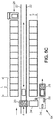
- FIG. 5A which is a schematic top view, it is expected to have a transfer / unload area on the left and to have a transfer / delivery area on the right. It is also proposed in this figure to have side by side shelves 2 each comprising three columns of housing. The length L of a shelf and its width l are adapted according to the size of the bins 12 to be stored in the housing 10.
- the Figure 5B represents an alternative embodiment of the Figure 5A . It is proposed here to have shelves 2 on both sides of the conveyor 4. The solution proposed here allows an optimization of the space as it will be clear to the skilled person.
- the Figure 5C still presents another variant embodiment.
- This variant is based on the embodiment of the Figure 5B but could also be adapted to the embodiment of the Figure 5A with shelves on one side of the conveyor 4.
- the picking carriage 28 arrives at the transfer zone for unloading it in a position such as the bins 12 that it transport are oriented at 90 ° to the position they must take on the conveyor 20 (and in the housing 10).
- a turning station 54 is then provided.
- the latter comprises, for example, a raceway 24 'similar to a raceway 24 of a shelf 2.
- This second raceway 24' is pivotally mounted so as to be able to pivot 90 ° while remaining in the same horizontal plane.
- this second raceway 24 ' is mounted on at least one motorized wheel 56 while being connected to a turning pivot 58.
- the turning station 54 has as many tracks 24 'superimposed that there can be bins 12 on a carriage 28.
- This turning station 54 is for example the following.
- a control carriage 28 is brought face to the turning station 54.
- An operator then controls the 90 ° rotation of the structure carrying the two superimposed raceways 24 'and located on levels adapted to the position of the bins 12 on the carriage 28.
- the operator pushes the two bins on the raceways 24'. They are then held by a barrier actuated by an electric jack (not shown). It then requests the return to 90 ° of the structure carrying the two raceways 24 '(and for example one or two bins 12).
- the raceways 24 ' are inclined relative to the horizontal so that the tanks 12 come into contact with the barrier by gravity.
- the bins 12 on the raceways 24 'are then aligned with the conveyor 20 of the carrier, ready to be unloaded.
- the actuator erases the barrier which held the tray to be unloaded on the raceway 24 'and releases the tray 12 which is received by the conveyor 20 to be stored in its housing 10 of destination.
- the turning angle could be different from 90 °. If the orientation of the tray in the housing 10 is important, a rotation of 180 ° is for example possible. A rotation of 270 ° can also be considered as well as all the intermediate angular values.
- a turning station can also be envisaged at the transfer zone used for the delivery of the bins 12 (with the delivery carriage 26.
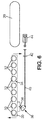
- the figure 6 illustrates a mechanism for moving a tray 12 from a housing 10 to the conveyor 20. There is recognized in this figure a raceway 24 and the conveyor 20.
- the raceway 24 is formed of a frame 30 in which are mounted rollers 32 arranged parallel to each other.
- the frame 30 is pivotally mounted about an axis 34 parallel to the rollers 32.
- a roller 36 cooperating with a cam 38 Under the frame 30, for example in a median position with respect to the length of the rollers 32, is a roller 36 cooperating with a cam 38.
- the roller 36 and the cam 38 are each mounted pivotally about an axis parallel to the 34.
- the roller 36 is mounted on the frame 30 while the cam 38 is mounted on the shelf 2, for example on a shelf 6 (below it).
- the cam 38 is controlled by means of a rod 40 which extends substantially parallel to the frame 30, below it.
- the cam 38 is disposed near the bottom of a housing 10 and the rod 40 extends towards the opening of the housing 10.
- the rod 40 is for example guided by a guide bearing 42 fixed under a shelf 6 (in a central position relative to an opening of a housing 10 if the cam 38 and the roller 36 are arranged in a median position relative to the raceway 24).
- rollers 32 there are four rollers 32 on one side of the axis 34 and five of the other.
- the presence of the roller 36 also creates an unbalance towards the bottom of the housing 10. If necessary, it is also possible to provide a return spring in the rest position of the frame 30, for example at the level of the housing. axis 34.
- This embodiment (that of figures 7 also) is simple because it allows to have only one cylinder to control all the tracks 24 of the housing 10.
- FIG. 7A and 7B An alternative embodiment of the tilt mechanism illustrated in the figure 6 is represented on the Figures 7A and 7B . It is recognized in these figures the raceway 24 with its rollers 32 and hinged about its axis 34 horizontal.
- the tilting mechanism illustrated here also includes a bead wire 40 'which interacts with the cylinder 44 (or other actuator) in the same manner as that illustrated in FIG. figure 6 . It further comprises a rocking assembly.
- the rocker assembly comprises two symmetrical flanges 60 connected by axes.
- Each flange 60 is for example made from a sheet cut to have an overall L shape.
- the two flanges 60 are arranged in a substantially vertical plane, perpendicular to the axis 34.
- the views 7A and 7B do not allow to see each time a single flange 60.
- Each flange 60 is pivotally mounted on a support 62, possibly common to the two flanges 60, fixed (for example welded) on the structure of the corresponding shelf 2.
- the fasteners of the flanges 60 on their support 62 define an articulation axis 64.
- Each flange 60 having an L shape, it has a first arm 66 and a second arm 68.
- the hinge pin 64 cuts the flanges 60 substantially halfway up the first arms 66.
- the ends of the first arms 66 are connected by an axis carrying at least one wheel 70 which is intended to come into contact with the raceway 24, the frame of the latter coming for example on the wheel (s) 70.
- the second arms 68 are connected by another axis which carries at least one counterweight 72.
- the L of the flanges 60 is oriented so that the first arm 66 is turned towards the raceway 24 (thus upwards since the rocker assembly is disposed under said raceway) and so that the second arm 68 is oriented opposite the conveyor 20, and therefore the rod 40 '.
- the rocker assembly is pivotable between two positions which are each stable. It is placed between the axis 34 and the conveyor 20 (or the conveyor 4). In the first rest position, the first arm 66 is slightly inclined relative to the vertical of the opposite side to the conveyor 20 (or to the conveyor 4): a straight line in a vertical plane passing through the axis hinge 64 and the axis bearing the (the) wheel (s) 70 is slightly inclined.
- a stop 74 for example in the form of a sheet fixed under the raceway, parallel to the rollers 32 is provided to receive the (the) wheel (s) 70 resting in the rest position of the raceway 24 This position is stable because, due to the inclination of the first arm 66, when the rocking assembly is pivoted to move the wheel (s) away from the abutment 74, it is necessary to slightly lift the raceway 24. This makes a hard point in the pivoting movement of the rocking assembly.
- the stop 74 comes to bear on a concave zone 76 formed at the junction between the first arm 66 and the second arm 68.
- the stop 74 is used for the stability of the two stable positions of the rocking assembly. It is clear that separate means could make it possible to obtain stability in the second position.
- a housing 10 When a housing 10 is empty and will receive a tray, its raceway 24 is in the so-called rest position, that is to say, inclined opposite the conveyor 4.
- the conveyor 20 arrives facing the housing 10, it is positioned to be at least at the height of the end of the tread 24 the highest, that is to say also closest to the conveyor 20.
- the latter can then transfer the tray 12 it carries to the housing 10 by rolling first on the conveyor alone, then on the conveyor and the raceway and finally on the raceway alone.
- the tray 12 Given the inclination of the raceway 24, the tray 12 is driven by gravity towards the end of the raceway 24 opposite the conveyor 20. It then comes into abutment at the end of the raceway.
- the stop may be integrated in the raceway 24, or to the shelf 2. It may also for example be a wall against which the shelf 2 would be.
- the conveyor 20 faces the housing 10 but in a position a little lower than that described above for the loading of the housing 10.
- the position of the conveyor 20 is such that the cylinder 44 can cooperate with the rod 40 or 40 '.
- the jack 44 When the jack 44 is actuated, it acts on the rod (40 or 40 ') which pivots the cam 38 ( figure 6 ) or the tilting assembly of the figure 7 (A and B).
- the raceway 24 then passes into its second position and by gravity, the tray 12 in the housing 10 rolls towards the conveyor 20 which then supports the tray 12.
- the cylinder 44 retracts and the raceway 24 returns to its first position.
- FIG. 8 illustrates a preferred embodiment of a picking preparation carriage 28.
- This carriage is for example designed to be operated by a central unit indicated by a command management software and an onboard automaton for functions.
- Subsidiaries assigned to the processing of several orders placed online to a merchant site via the internet or via any other means of communication.
- a merchant site has one (or more) store (s) for storing the products offered for sale, each of these stores comprising product storage gondolas or the like, separated by aisles.
- each gondola is formed of a supporting frame and several horizontal shelves, carried by the supporting frame. Products offered for sale are stored on horizontal shelves.
- the picking preparation carriage 28 comprises a rigid chassis, low ground clearance, mounted on five wheels namely two front wheels 46, two central wheels 47 and a rear wheel 48 free also.
- the front wheels 46 and the rear wheel are for example free while the two central wheels 47 are driving, each drive wheel having its own motor.
- the two wheels thus form the propulsion unit which is connected to the central unit via the onboard PLC and a drive.
- the propulsion unit is supplied with electrical energy by an on-board rechargeable electric power source formed of electric batteries.
- the controller allows, via the drive, different speed commands to one or the other element of the propulsion unit, thus allowing the direction of the truck to be changed.
- the frame of the carriage is for example formed of two parallel longitudinal members, and joined to each other by front and rear rails.
- This carriage also includes side flanks parallel to its direction and front and rear flanks transverse to its direction of advancement.
- On this chassis is a platform forming a cockpit 50 provided to receive a preparer. Thus the preparer is embedded on the cart.
- the carriage Adjacent to the cockpit 50, the carriage has two handles 52 to be held by the preparer standing on the platform when moving the carriage. These handles 52 allow the preparer to secure his balance. It is advantageously provided that the absence of "presence" of a hand on a single handle controls the stopping of the propulsion unit.
- the picking carriage 28 On the side of the platform opposite the side having the handles 52 for holding and safety, the picking carriage 28 is equipped with a magazine adapted to removably receive a plurality of trays 12. These are arranged in the store so superimposed and each of them is intended to receive the items of one of the commands to be processed by the preparer.
- the layout of a store equipped with several bins 12 allows the simultaneous processing of several orders.
- the cockpit 50 is open laterally so that the preparer can easily access the products stored in the gondolas.
- the preparer is standing in the cockpit.
- the magazine is located at the rear of the carriage 1.
- the magazine is formed of a supporting framework defining, in successive height levels, several housings respectively adapted to removably receive the bins 12. Each housing is open both forwards and backwards to allow the removal or placement of each tray 12 is from the rear of the truck or from the cockpit 50.
- each tray 12 is slidably mounted in its housing to be able to be pulled backwards or pushed forward, depending on the configuration chosen, by the preparer. view of the introduction of the different items ordered.
- each housing comprises a horizontal bottom provided to support the corresponding tray 12. This horizontal bottom is formed of a raceway 24 'formed by a frame 30' and a succession of horizontal rollers 32 'carried by the frame 30' and freely rotatably mounted in the latter, each along a geometric axis perpendicular to the direction of carriage advancement.
- the horizontal bottom is movably mounted in horizontal translation and for this purpose is slidably carried by horizontal slides fixed to the frame of the magazine and extending parallel to the direction of advance of the preparation trolley.
- the purpose of such a configuration is to make it possible to arrange the horizontal movable floor in a rear overhang with respect to the framework of the store in order to facilitate the operations of loading and unloading the containers 12 from the rear of the store.
- the movable bottom occupies a retracted position in the frame of the store.
- each slide has a front end stop to prevent the horizontal bottom of the housing from entering the cockpit 50.
- each slide has a rear stop capable of limiting the rearward movement of the bottom of the housing. each housing and consequently the importance of the rear overhang.
- Each housing on the picking carriage 28 is associated locking means adapted in the locking position to maintain the tray 12 on its raceway 24 ', the locking means being operable from the cockpit 50.
- This means of locking may be constituted by an axle longitudinally passing through the frame 30 'with a rotary handle end axis, operable from the cockpit 50 and a stop perpendicular to the axis of the opposite side to the rotary handle. In the working position, the stop is disposed on the path of the tray 12 to maintain the latter in the usual position of use. In the delivery position of the tray 12 to the conveyor 4, or any other storage location, the preparer unlocks the stop by rotating a quarter turn of the rotary handle, thus releasing the tray 12 which can then be pushed to the outside to the conveyor 20.
- the storage and transfer device proposed here makes it possible with simple means to optimize the management of orders prepared in a shop of a commercial site.
- this device can also find applications in an industrial site for the preparation of batches of parts or for the production of various lots - spare parts, assembly subassemblies, ....
- the system proposed here also has the advantage of being compact. It is also flexible. Indeed, it can adapt to many styles of management. Order preparations can be managed on one side and deliveries on the other.
- the system described with reference to the figures comprises a conveyor with a single conveyor. It can be envisaged to have at least two conveyors to increase the productivity of the system. With two conveyors, one could for example provide that the two conveyors are mounted on the same mast 18 or have two separate sets each formed of a mast and a conveyor.
Abstract
Ce dispositif de stockage et de transfert de bacs (12) comporte : - une étagère (2) présentant des logements (10) disposés côte à côte et destinés chacun à recevoir un bac (12) par une ouverture de chargement/déchargement, chaque logement (10) comportant un chemin de roulement (24) inclinable entre une première position dite de repos et une seconde position inclinée vers l'ouverture de chargement/déchargement, - des moyens (4) permettant d'apporter un bac (12) face à un logement (10), comportant, un convoyeur (20) mobile permettant de déplacer un bac (12) dans une direction sensiblement horizontale et des moyens permettant de déplacer le convoyeur (20). Le convoyeur (20) mobile est pourvu d'un actionneur (44). À chaque chemin de roulement (24) est associé un mécanisme d'inclinaison permettant de faire passer le chemin de roulement (24) correspondant de sa première position à sa seconde position et muni de moyens de coopération avec l'actionneur (44).This tray storage and transfer device (12) comprises: - a shelf (2) having housings (10) arranged side by side and each intended to receive a tray (12) through a loading / unloading opening, each housing (10) having a raceway (24) tilting between a first so-called rest position and a second inclined position towards the loading / unloading opening, - Means (4) for providing a tray (12) facing a housing (10), comprising a movable conveyor (20) for moving a tray (12) in a substantially horizontal direction and means for moving the conveyor (20). The moving conveyor (20) is provided with an actuator (44). Each raceway (24) is associated with a tilting mechanism for passing the corresponding raceway (24) from its first position to its second position and provided with cooperation means with the actuator (44).
Description
La présente invention concerne un dispositif de stockage et de transfert de bacs ou tout autre type de réceptacles.The present invention relates to a storage device and transfer trays or any other type of receptacles.
L'objet de l'invention est destiné notamment au traitement de commandes de marchandises au sein par exemple d'une société de vente par Internet. Toutefois, comme il apparaitra à l'homme du métier, d'autres applications peuvent être envisagées. Ainsi par exemple l'invention pourrait être mise en oeuvre pour la gestion d'un stock de pièces, par exemple des pièces détachées, dans tout type d'industrie.The object of the invention is intended in particular for the processing of orders for goods within, for example, an Internet sales company. However, as will be apparent to those skilled in the art, other applications may be considered. Thus for example the invention could be implemented for managing a stock of parts, for example spare parts, in any type of industry.
Dans le domaine du commerce sur Internet, un client fait une commande en ligne. Il convient alors de préparer les articles commandés pour les faire parvenir au client. Dans certains cas, le client vient prendre les produits sur un lieu de stockage/vente, dans d'autres cas les produits sont expédiés depuis le site marchand.In the field of Internet commerce, a customer places an order online. It is then necessary to prepare the items ordered to send them to the customer. In some cases, the customer comes to take the products on a place of storage / sale, in other cases the products are shipped from the merchant site.
La préparation de la commande peut se faire de diverses manières. Il peut s'agir d'un système entièrement automatisé qui permet de collecter dans un stock des articles pour les disposer dans un bac ou similaire. À l'inverse, il peut s'agir d'une préparation manuelle dans laquelle un opérateur/préparateur muni d'un chariot passe dans des rayonnages et prépare la commande un peu de la même manière qu'un client fait ses courses dans un supermarché.The preparation of the order can be done in various ways. This may be a fully automated system that collects items from a stock for disposal in a bin or the like. Conversely, it can be a manual preparation in which an operator / preparer with a trolley passes through shelves and prepares the order in much the same way that a customer shopping in a supermarket .
Dans tous les cas, il se pose ensuite le problème de la gestion des commandes préparées entre le moment où tous les éléments commandés ont été regroupés dans un même bac et le moment où ces éléments sont expédiés ou remis au client.In all cases, there is then the problem of the management of the orders prepared between the moment when all the ordered items have been grouped in the same bin and the moment when these items are sent or delivered to the customer.
Généralement, une zone de stockage est prévue et un système de gestion des commandes gère également les manutentions dans cette zone. Il peut s'agir d'une gestion empirique ou bien de type FIFO (du sigle anglais First In, First Out, soit en français : premier entré, premier sorti) ou d'un autre type encore.Generally, a storage area is provided and an order management system also handles handling in this area. It may be an empirical management or type FIFO (First In, First Out, or French: first-in, first-out) or another type.
La présente invention a pour but de fournir des moyens permettant d'optimiser une gestion de stock, par exemple un stock de lots divers correspondant à des commandes d'articles, permettant de faciliter le travail des opérateurs tant lorsqu'une commande est amenée vers la zone de stockage que lorsque cette commande doit être retirée de ladite zone de stockage pour être délivrée ou expédiée.The present invention aims to provide means for optimizing a stock management, for example a stock of various batches corresponding to orders of articles, to facilitate the work of operators as a command is brought to the storage area only when this command is to be removed from said storage area for be delivered or shipped.
De préférence, les moyens proposés seront de conception simplePreferably, the proposed means will be of simple design
À cet effet, la présente invention propose un dispositif de stockage et de transfert de bacs (ou tout autre réceptacle) comportant :
- une étagère présentant des logements disposés côte à côte sur au moins deux niveaux et destinés chacun à recevoir un bac par une ouverture de chargement/déchargement, chaque logement comportant un chemin de roulement monté pivotant autour d'un axe sensiblement horizontal et inclinable entre une première position dite de repos et une seconde position inclinée vers l'ouverture de chargement/déchargement,
- des moyens permettant d'apporter un bac face à un logement, comportant, d'une part, un convoyeur mobile permettant de déplacer un bac dans une direction sensiblement horizontale et, d'autre part, des moyens permettant de déplacer le convoyeur dans un plan sensiblement perpendiculaire à la direction de déplacement d'un bac sur le convoyeur
- a shelf having housings arranged side by side on at least two levels and each intended to receive a tray through a loading / unloading opening, each housing having a raceway pivotally mounted about a substantially horizontal axis and tilting between a first so-called rest position and a second inclined position towards the loading / unloading opening,
- means for providing a tray facing a housing, comprising, on the one hand, a movable conveyor for moving a tray in a substantially horizontal direction and, on the other hand, means for moving the conveyor in a plane substantially perpendicular to the direction of travel of a ferry on the conveyor
Selon la présente invention, le convoyeur mobile est pourvu d'un actionneur, et à chaque chemin de roulement est associé un mécanisme d'inclinaison permettant de faire passer le chemin de roulement correspondant de sa première position à sa seconde position, ledit mécanisme étant muni de moyens de coopération avec l'actionneur.According to the present invention, the mobile conveyor is provided with an actuator, and each raceway is associated with a tilting mechanism for passing the corresponding raceway from its first position to its second position, said mechanism being provided with means of cooperation with the actuator.
Cette structure présente l'avantage d'être simple et de ce fait aussi facilement automatisable. Le fait de simplement prévoir d'incliner un bac pour le faire sortir de son logement en coopération avec un convoyeur est avantageux car il permet d'avoir avec des moyens simples une action rapide et facilement commandable.This structure has the advantage of being simple and therefore easy to automate. Simply providing to incline a tray to take it out of its housing in cooperation with a conveyor is advantageous because it allows to have simple means fast action and easily controllable.
Selon une première variante, le mécanisme d'inclinaison comporte un ensemble basculant disposé sous le chemin de roulement et monté mobile en rotation par rapport à un axe parallèle à l'axe chemin de roulement, le chemin de roulement venant en appui ledit ensemble basculant formant une came de telle sorte que lorsqu'il passe d'une première position angulaire à une seconde position angulaire il commande le passage du chemin de roulement de sa première position dite de repos à sa seconde position. Dans cette variante, on peut aussi prévoir que le mécanisme d'inclinaison est en outre muni d'une tige de commande reliée à l'ensemble basculant et destinée à coopérer avec l'actionneur.According to a first variant, the tilting mechanism comprises a tilting assembly disposed under the raceway and rotatably mounted relative to an axis parallel to the raceway axis, the raceway bearing against said tilting assembly forming a cam so that when it passes from a first angular position to a second angular position it controls the passage of the race from its first rest position to its second position. In this variant, it can also be provided that the tilting mechanism is further provided with a rod control unit connected to the rocker assembly and intended to cooperate with the actuator.
Avantageusement, pour favoriser le retour en position de repos, le mécanisme d'inclinaison comporte un contrepoids tendant à le ramener dans sa première position angulaire.Advantageously, to promote the return to the rest position, the tilting mechanism comprises a counterweight tending to bring it back to its first angular position.
Selon une variante de réalisation du dispositif de transfert et de stockage l'ensemble basculant peut être une came.According to an alternative embodiment of the transfer and storage device, the rocking assembly can be a cam.
Une variante préférée prévoit que l'ensemble basculant présente deux flasques latéraux parallèles reliés entre eux par au moins un axe portant au moins une roulette destinée à venir en contact avec le chemin de roulement.A preferred variant provides that the rocker assembly has two parallel side flanges interconnected by at least one axis carrying at least one wheel intended to come into contact with the raceway.
Dans une forme de réalisation du dispositif de stockage et de transfert proposé ici, les moyens permettant de déplacer le convoyeur comportent par exemple un chariot mobile horizontalement selon une direction et portant un mât vertical le long duquel le convoyeur peut se déplacer. Pour un meilleur guidage de ce chariot mobile horizontalement, ce dernier se déplace avantageusement sur des rails.In one embodiment of the storage and transfer device proposed here, the means for moving the conveyor comprise for example a carriage movable horizontally in one direction and carrying a vertical mast along which the conveyor can move. For better guidance of this horizontally movable carriage, it moves advantageously on rails.
Un dispositif de transfert et de stockage tel que décrit ci-dessus peut également comporter un chariot motorisé présentant :
- un châssis sur lequel est ménagée une plateforme permettant de recevoir un opérateur,
- des moyens de commande disposés d'un côté de la plateforme, et
- du côté de la plateforme opposé au côté muni des moyens de commande, au moins deux logements disposés l'un au-dessus de l'autre et munis chacun d'un chemin de roulement et de moyens de blocage pour un bac disposé sur le chemin de roulement.
- a chassis on which is formed a platform for receiving an operator,
- control means arranged on one side of the platform, and
- on the side of the platform opposite the side provided with the control means, at least two housings arranged one above the other and each provided with a raceway and locking means for a tray disposed on the road rolling.
Dans un mode de réalisation préféré, il est prévu que chaque chemin de roulement du chariot soit monté sur des glissières de manière à pouvoir se déplacer entre une position dite de transport dans laquelle le chemin de roulement est au-dessus du châssis et une position dite de transfert dans laquelle le chemin de roulement est en porte-à-faux à l'extérieur du châssis. Ce mode de réalisation facilite la coopération du chariot motorisé avec le convoyeur.In a preferred embodiment, it is provided that each raceway of the carriage is mounted on slides so as to be able to move between a so-called transport position in which the raceway is above the chassis and a so-called position. transfer in which the raceway is cantilevered outside the frame. This embodiment facilitates the cooperation of the motorized carriage with the conveyor.
Dans une forme de réalisation préférée qui permet d'optimiser l'utilisation de la surface disponible, il est prévu que le dispositif de transfert et de stockage comporte deux étagères disposées en vis-à-vis, les moyens permettant d'apporter un bac face à un logement étant disposés entre les deux étagères. Pour augmenter les cadences de stockage et déstockage, on peut également prévoir que le dispositif de transfert et de stockage comporte deux convoyeurs ou plus,In a preferred embodiment that optimizes the use of the available surface, it is expected that the transfer device and storage comprises two shelves arranged vis-à-vis, the means for providing a tray facing a housing being disposed between the two shelves. To increase the rates of storage and retrieval, it is also possible that the transfer device and storage comprises two or more conveyors,
Enfin, la présente invention concerne également un magasin, caractérisé en ce qu'il comporte :
- un dispositif de stockage et de transfert tel que décrit ci-dessus
- une zone de transfert disposée d'un premier côté du dispositif de transfert et de stockage destinée au transfert d'un bac ou similaire vers le dispositif de transfert et de stockage, et
- une zone de transfert disposée d'un côté opposé au premier côté du dispositif de transfert et de stockage destinée au transfert d'un bac ou similaire depuis le dispositif de transfert et de stockage vers un chariot.
- a storage and transfer device as described above
- a transfer zone disposed on a first side of the transfer and storage device for transferring a tray or the like to the transfer and storage device, and
- a transfer zone disposed on a side opposite to the first side of the transfer and storage device for transferring a tray or the like from the transfer and storage device to a carriage.
Un tel magasin peut comporter en outre un poste de retournement permettant de faire pivoter à l'horizontale un bac ou similaire, un tel poste de retournement étant prévu sur l'une et/ou l'autre des zones de transfert.Such a store may further comprise a turning station for pivoting horizontally a tray or the like, such a turning station being provided on one and / or the other of the transfer zones.
Enfin, la présente invention concerne aussi un procédé de stockage et de déstockage d'une commande préparée dans un bac ou similaire, caractérisé en ce qu'il comporte les étapes suivantes :
- dépose du bac sur un convoyeur mobile au niveau d'un premier poste de transfert,
- déplacement du convoyeur mobile pour l'amener face à un logement d'une étagère, ledit logement étant muni d'un chemin de roulement monté pivotant autour d'un axe sensiblement horizontal entre une première position dite de repos et une seconde position dite de chargement/déchargement,
- transfert du bac du convoyeur vers le logement de l'étagère,
- retrait du convoyeur,
- amenée du convoyeur face au logement contenant le bac,
- action à l'aide d'un actionneur fixé au convoyeur sur un mécanisme afin de faire passer le chemin de roulement du logement de sa première position vers sa seconde position,
- transfert du bac depuis son logement vers le convoyeur,
- déplacement du convoyeur et du bac vers un second poste de transfert, et
- transfert du bac en vue de sa livraison.
- removing the tray on a mobile conveyor at a first transfer station,
- moving the movable conveyor to bring it facing a housing of a shelf, said housing being provided with a raceway pivotally mounted about a substantially horizontal axis between a first so-called rest position and a second so-called loading position /unloading,
- transfer of the ferry from the conveyor to the housing of the shelf,
- removal of the conveyor,
- brought from the conveyor facing the housing containing the tray,
- action using an actuator attached to the conveyor on a mechanism to move the raceway housing from its first position to its second position,
- transfer of the tray from its housing to the conveyor,
- moving the conveyor and the bin to a second transfer station, and
- transfer of the bin for delivery.
Des détails et avantages de la présente invention apparaîtront mieux de la description qui suit, faite en référence au dessin schématique annexé sur lequel :
- La
figure 1 est une vue schématique de face illustrant un dispositif de stockage et de transfert, - La
figure 2 est une vue de côté schématique du dispositif de stockage et de transfert de lafigure 1 , - La
figure 3 est une vue en élévation de face plus détaillée illustrant un chargement dans un dispositif de stockage et de transfert, - La
figure 4 est une vue similaire à lafigure 1 illustrant un déchargement à partir du dispositif de stockage et de transfert, - Les
figures 5A, 5B et5C sont chacune une vue de dessus du dispositif de stockage et de transfert des figures précédentes dans trois configurations différentes, - La
figure 6 est une vue d'un détail à échelle agrandie de lafigure 4 , - Les
figures 7A et 7B sont des vues correspondant à la vue de lafigure 6 pour une variante de réalisation dans deux positions distinctes, et - La figure 8 est une vue d'un chariot pouvant être utilisé en coopération avec un dispositif de stockage et de transfert des figures précédentes.
- Les
figures 1 illustrent schématiquement un dispositif de stockage et de transfert et son principe de fonctionnement. Ce dispositif comporte, d'une part,et 2une étagère 2 et, d'autre part,un transporteur 4.
- The
figure 1 is a schematic front view illustrating a storage and transfer device, - The
figure 2 is a schematic side view of the storage and transfer device of thefigure 1 , - The
figure 3 is a more detailed front elevational view illustrating a loading in a storage and transfer device, - The
figure 4 is a view similar to thefigure 1 illustrating unloading from the storage and transfer device, - The
Figures 5A, 5B and5C are each a top view of the storage and transfer device of the preceding figures in three different configurations, - The
figure 6 is a view of an enlarged detail of thefigure 4 , - The
Figures 7A and 7B are views corresponding to the view of thefigure 6 for an alternative embodiment in two distinct positions, and - FIG. 8 is a view of a carriage that can be used in cooperation with a storage and transfer device of the preceding figures.
- The
Figures 1 and 2 schematically illustrate a storage and transfer device and its operating principle. This device comprises, on the one hand, ashelf 2 and, on the other hand, aconveyor 4.
L'étagère 2 est un meuble, qui dans la forme de réalisation présentée est sur pieds. Elle comporte des tablettes 6 horizontales superposées ainsi que des montants 8 verticaux. Ces tablettes 6 et montants 8 définissent ainsi des logements 10 de taille adaptée pour recevoir un bac 12. Dans l'exemple montré sur la
Le transporteur 4 est destiné à disposer un bac 12 dans n'importe quel logement 10 ou à l'y récupérer. Dans la forme de réalisation illustrée, ce transporteur 4 présente un châssis 14 muni de roues 16. Le châssis 14 est motorisé et porte un mât 18 s'étendant verticalement. Un convoyeur 20 se déplace le long du mât 18. Le convoyeur 20 est muni d'un tapis roulant qui est guidé sur deux rouleaux parallèles motorisés permettant ainsi de convoyer un bac 12 (ou bien sûr tout autre type d'objet) selon une direction horizontale transversale par rapport à la direction de déplacement du transporteur 4, dans les deux sens possibles.The
Le transporteur 4 est bien entendu adapté à l'étagère 2, ou inversement. Tout d'abord, on remarque que les logements 10 de l'étagère 2 présentent tous une ouverture permettant d'y accéder et que d'un même côté de l'étagère 2, toutes les ouvertures sont dans un même plan vertical. Le transporteur 4 est prévu pour se déplacer parallèlement à ce plan vertical contenant les ouvertures des logements 10 de l'étagère 2. Pour le déplacement horizontal du transporteur 4, les roues 16 sont par exemple guidées par des rails 22 (
Sur la
Les
On prend comme exemple ici un magasin d'un commerce connu sous le nom de "drive". Ici des clients choisissent sur Internet, en ligne, les produits qu'ils souhaitent acheter. Il s'agit des produits que l'on trouve habituellement dans un supermarché ou hypermarché avec notamment des produits alimentaires, mais pas uniquement. Une fois la commande passée et réglée, les articles commandés sont préparés et sont disposés dans un chariot de livraison 26 (
Le dispositif proposé ici permet de gérer les commandes des clients entre le moment où tous les articles ont été collectés et le moment où le client vient les récupérer.The device proposed here makes it possible to manage the orders of the customers between the moment when all the articles were collected and the moment when the customer comes to recover them.
De manière classique, lorsqu'une commande est reçue, les articles commandés sont collectés dans un bac 12. Généralement, la taille d'un bac 12 est adaptée à la taille des commandes habituelles et les commandes nécessitant d'utiliser deux bacs 12 sont minoritaires. On supposera donc ici qu'à chaque bac 12 correspond une commande d'un client. Le volume du bac est par exemple compris entre quelques litres et 200 l.Conventionally, when an order is received, the items ordered are collected in a
Un opérateur se déplace alors par exemple dans un magasin dans lequel sont stockés les articles proposés à la vente. Il est équipé d'un chariot de préparation de commande 28 qui peut être un chariot motorisé ou non. Selon une forme de réalisation préférée, il s'agit d'un chariot motorisé tel le chariot de préparation de commande illustré sur la figure 8 et décrit plus loin.An operator then moves for example in a store in which are stored the items offered for sale. It is equipped with a picking
Dans l'exemple de réalisation qui suit, on supposera que le chariot de préparation de commande 28 est prévu pour préparer deux commandes à la fois et il comporte deux niveaux, chacun recevant un bac 12. Dans une forme de réalisation préférée, le chariot de préparation de commande 28 présente deux chemins de roulement 24' disposés par exemple l'un au-dessus de l'autre.In the following exemplary embodiment, it will be assumed that the picking
Le chariot de préparation de commande 28 est amené à un poste de transfert/déchargement aménagé par exemple à proximité d'une extrémité des rails 22 du transporteur 4. Ce dernier est alors amené face au chariot de préparation de commande 28 et le convoyeur 20 est placé à hauteur d'un bac 12 à décharger. Le bac 12 est posé sur un chemin de roulement 24'. Pour éviter qu'il ne roule sur ce chemin de roulement 24', il est prévu un système de verrous non représenté. Il peut s'agir ici simplement de deux loquets mobiles en rotation entre une position de verrouillage et une position de déverrouillage, le bac à maintenir en position venant prendre place entre les deux loquets lorsque ceux-ci sont en position de verrouillage. Les deux loquets peuvent être reliés par une tringle qui forme aussi l'axe de rotation des loquets. Ainsi, en actionnant un loquet, l'autre est automatiquement actionné également. Les deux loquets sont alors aussi toujours dans un même état (verrouillé ou déverrouillé).The picking
Lorsque le convoyeur 20 est à bonne hauteur et que le système de verrouillage est dans sa position déverrouillée, le bac 12 est poussé en direction du convoyeur 20. Même si le poids du bac 12 est important, grâce au chemin de roulement 24', l'effort à exercer est faible pour initier le déplacement du bac 12 vers le convoyeur 20. Dès que le bac 12 arrive au contact du convoyeur 20, ce dernier vient entrainer le bac 12 jusqu'à ce qu'il soit entièrement sur le convoyeur 20. Le bac 12 est alors transporté sur le convoyeur 20 jusqu'à se trouver face au logement 10 dans lequel il doit prendre place. Une fois en place face au logement 10, le convoyeur 20 est remis en marche pour diriger le bac 12 vers le logement 10. Pour garantir un bon positionnement du bac 12 dans son logement 10, il est prévu que le chemin de roulement 24 du logement 10 soit légèrement incliné par rapport à l'horizontale de manière à entrainer le bac 12 vers le fond du logement 10. Le fond du logement peut être par exemple fermé par une paroi (opposée donc à l'ouverture par laquelle le bac 12 a été introduit dans le logement 10). Il est aussi possible de prévoir simplement une butée qui peut prendre une forme quelconque : barre transversale, butoir, ....When the
La
Le convoyeur 20 est alors tout d'abord conduit face au logement 10 contenant le bac 12 à récupérer.The
Il est alors proposé de faire glisser le bac 12 à récupérer sur le convoyeur 20. Pour ce faire, comme suggéré en haut à droite de la
Sur la
La
La
Dans le cas où un chariot 28 peut transporter plusieurs bacs 12, on peut prévoir que le poste de retournement 54 comporte autant de chemins de roulement 24' superposés qu'il peut y avoir de bacs 12 sur un chariot 28.In the case where a
Le fonctionnement avec ce poste de retournement 54 est par exemple le suivant. Un chariot de commande 28 est amené face au poste de retournement 54. Un opérateur commande alors la rotation à 90° de la structure portant les deux chemins de roulement 24' superposés et situés à des niveaux adaptés à la position des bacs 12 sur le chariot 28.The operation with this turning
En fin de rotation, lorsque la structure avec les deux chemins de roulement 24' se trouve dans le prolongement arrière du chariot, l'opérateur pousse les deux bacs sur les chemins de roulement 24'. Ils sont alors retenus par une barrière actionnée par un vérin électrique (non représentés). Il demande ensuite le retour à 90° de la structure portant les deux chemins de roulement 24' (et par exemple un ou deux bacs 12). Les chemins de roulement 24' sont inclinés par rapport à l'horizontale pour que les bacs 12 viennent en contact avec la barrière par gravité. Les bacs 12 sur les chemins de roulement 24' sont alors alignés avec le convoyeur 20 du transporteur, prêts à être déchargés. Lorsque le convoyeur est à bonne hauteur, l'actionneur efface la barrière qui maintenait le bac à décharger sur le chemin de roulement 24' et libère le bac 12 qui est réceptionné par le convoyeur 20 pour être stocké dans son logement 10 de destination.At the end of rotation, when the structure with the two raceways 24 'is in the rear extension of the carriage, the operator pushes the two bins on the raceways 24'. They are then held by a barrier actuated by an electric jack (not shown). It then requests the return to 90 ° of the structure carrying the two raceways 24 '(and for example one or two bins 12). The raceways 24 'are inclined relative to the horizontal so that the
Différentes variantes du poste de retournement peuvent être envisagées. L'angle de retournement pourrait être différent de 90°. Si l'orientation du bac dans le logement 10 est importante, une rotation de 180° est par exemple envisageable. Une rotation de 270° peut aussi être envisagée de même que toutes les valeurs angulaires intermédiaires.Different variants of the turning station can be envisaged. The turning angle could be different from 90 °. If the orientation of the tray in the
Bien entendu, un poste de retournement peut aussi être envisagé au niveau de la zone de transfert utilisée pour la livraison des bacs 12 (avec le chariot de livraison 26.Of course, a turning station can also be envisaged at the transfer zone used for the delivery of the bins 12 (with the
La
De manière classique, le chemin de roulement 24 est formé d'un cadre 30 dans lequel sont montés des rouleaux 32 disposés parallèlement les uns par rapport aux autres. Le cadre 30 est monté pivotant autour d'un axe 34 parallèle aux rouleaux 32.Conventionally, the
Sous le cadre 30, par exemple en position médiane par rapport à la longueur des rouleaux 32, se trouve un galet 36 coopérant avec une came 38. Le galet 36 et la came 38 sont montés chacun pivotants autour d'un axe parallèle à l'axe 34. Le galet 36 est monté sur le cadre 30 tandis que la came 38 est montée sur l'étagère 2, par exemple sur une tablette 6 (en dessous de celle-ci). La came 38 est commandée à l'aide d'une tringle 40 qui s'étend sensiblement parallèlement au cadre 30, sous celui-ci. La came 38 est disposée près du fond d'un logement 10 et la tringle 40 s'étend vers l'ouverture du logement 10. La tringle 40 est par exemple guidée par un palier 42 de guidage fixé sous une tablette 6 (en position centrale par rapport à une ouverture d'un logement 10 si la came 38 et le galet 36 sont disposés en position médiane par rapport au chemin de roulement 24).Under the
De manière tout à fait originale, il est proposé de commander la tringle 40, et donc la came 38, depuis le convoyeur 20, ou plus précisément à l'aide d'un actionneur qui peut être par exemple un vérin 44, pneumatique ou autre, solidaire du convoyeur 20. Un moteur, électrique de préférence, peut aussi être envisagé comme actionneur. On prévoit sur la
Quand le vérin 44 est actionné, sa tige se déplace en direction de la tringle 40 et vient la pousser. Ce mouvement (essentiellement) de translation de la tringle 40 commande le pivotement de la came 38 qui est conformée de telle sorte que ce mouvement entraine une poussée vers le haut sur le galet 36 et donc sur l'arrière du cadre (la partie arrière étant considérée ici comme celle se trouvant au niveau du fond du logement correspondant.When the
Cette forme de réalisation (celle des
Une variante de réalisation du mécanisme d'inclinaison illustré sur la
L'ensemble basculant comporte deux flasques 60 symétriques reliés par des axes. Chaque flasque 60 est par exemple réalisé à partir d'une tôle découpée de manière à présenter une forme globale en L. Les deux flasques 60 sont disposés dans un plan sensiblement vertical, perpendiculaire à l'axe 34. Les vues 7A et 7B ne permettent de voir à chaque fois un seul flasque 60. Chaque flasque 60 est monté pivotant sur un support 62, éventuellement commun aux deux flasques 60, fixé (par exemple soudé) sur la structure de l'étagère 2 correspondante. Les fixations des flasques 60 sur leur support 62 définissent un axe d'articulation 64.The rocker assembly comprises two
Chaque flasque 60 présentant une forme en L, il présente un premier bras 66 et un second bras 68. L'axe d'articulation 64, dans la forme de réalisation représentée, coupe les flasques 60 sensiblement à mi-hauteur des premiers bras 66. Les extrémités des premiers bras 66 sont reliées par un axe portant au moins une roulette 70 qui est destinée à venir en contact avec le chemin de roulement 24, le cadre de ce dernier venant par exemple en appui sur la (les) roulette(s) 70.Each
Les seconds bras 68 sont quant à eux reliés par un autre axe qui porte au moins un contrepoids 72.The
Le L des flasques 60 est orienté de telle sorte que le premier bras 66 soit tourné vers le chemin de roulement 24 (donc vers le haut puisque l'ensemble basculant est disposé sous ledit chemin de roulement) et de telle sorte que le second bras 68 soit orienté à l'opposé du convoyeur 20, et donc de la tringle 40'.The L of the
L'ensemble basculant peut pivoter entre deux positions qui sont chacune stables. Il est placé entre l'axe 34 et le convoyeur 20 (ou le transporteur 4). Dans la première position, dite de repos, le premier bras 66 est légèrement incliné par rapport à la verticale du côté opposé au convoyeur 20 (ou au transporteur 4) : une droite dans un plan vertical passant par l'axe d'articulation 64 et par l'axe portant la (les) roulette(s) 70 est légèrement incliné. Une butée 74 se présentant par exemple sous la forme d'une tôle fixée sous le chemin de roulement, parallèlement aux rouleaux 32 est prévue pour recevoir la (les) roulette(s) 70 en appui dans la position de repos du chemin de roulement 24. Cette position est stable car du fait de l'inclinaison du premier bras 66, lorsque l'ensemble basculant est pivoté pour éloigner la (les) roulettes de la butée 74, il faut légèrement soulever le chemin de roulement 24. On réalise ainsi un point dur dans le mouvement pivotant de l'ensemble basculant.The rocker assembly is pivotable between two positions which are each stable. It is placed between the
Pour avoir une seconde position stable de l'ensemble basculant, il est prévu que la butée 74 vienne en appui sur une zone concave 76 ménagée à la jonction entre le premier bras 66 et le second bras 68. Ici la butée 74 est utilisée pour la stabilité des deux positions stables de l'ensemble basculant. Il est clair que des moyens distincts pourraient permettre d'obtenir la stabilité dans la seconde position.To have a second stable position of the rocker assembly, it is provided that the
Lorsqu'un logement 10 est vide et qu'il va recevoir un bac, son chemin de roulement 24 est dans la position dite de repos, c'est-à-dire incliné à l'opposé du transporteur 4. Lorsque le convoyeur 20 arrive face au logement 10, il se positionne pour être au moins à la hauteur de l'extrémité du chemin de roulement 24 la plus élevée, c'est-à-dire aussi la plus proche du convoyeur 20. Ce dernier peut alors transférer le bac 12 qu'il porte vers le logement 10 en le faisant rouler tout d'abord sur le convoyeur seul, puis sur le convoyeur et le chemin de roulement puis enfin sur le chemin de roulement seul. Compte tenu de l'inclinaison du chemin de roulement 24, le bac 12 est conduit par gravité vers l'extrémité du chemin de roulement 24 opposée au convoyeur 20. Il arrive alors en butée au bout du chemin de roulement. La butée peut être intégrée au chemin de roulement 24, ou bien à l'étagère 2. Il peut aussi par exemple s'agir d'un mur contre lequel se trouverait l'étagère 2.When a
Pour récupérer un bac 12 se trouvant dans un logement 10, le convoyeur 20 vient face au logement 10 mais dans une position un peu plus basse que celle décrite plus haut pour le chargement du logement 10. La position du convoyeur 20 est telle que le vérin 44 puisse coopérer avec la tringle 40 ou 40'. Lorsque le vérin 44 est actionné, il agit sur la tringle (40 ou 40') qui vient faire pivoter la came 38 (
La figure 8 illustre quant à elle une forme de réalisation préférée d'un chariot de préparation de commande 28. Ce chariot est par exemple prévu pour être manoeuvré par une unité centrale renseignée par un logiciel de gestion des commandes et un automate embarqué pour des fonctions subsidiaires, affecté au traitement de plusieurs commandes passées en ligne à un site marchand via l'internet ou via tout autre mode de communication. Un tel site marchand, comme connu, possède un (ou plusieurs) magasin(s) de stockage des produits proposés à la vente, chacun de ces magasins comportant des gondoles de stockage des produits ou équivalents, séparées par des allées de circulation. Typiquement, chaque gondole est formée d'une ossature porteuse et de plusieurs tablettes horizontales, portées par l'ossature porteuse. Les produits proposés à la vente sont stockés sur les tablettes horizontales.FIG. 8 illustrates a preferred embodiment of a picking
Le chariot de préparation de commande 28 comprend un châssis rigide, à faible garde au sol, monté sur cinq roues à savoir deux roues avant 46, deux roues centrales 47 et une roue arrière 48 libre également. Les roues avant 46 et la roue arrière sont par exemple libres tandis que les deux roues centrales 47 sont motrices, chaque roue motrice possédant sa propre motorisation. Les deux roues forment ainsi le groupe de propulsion qui est connecté à l'unité centrale via l'automate embarqué et un variateur. Le groupe de propulsion est alimenté en énergie électrique par une source d'énergie électrique embarquée, rechargeable, formée de batteries électriques. L'automate permet via le variateur, des commandes de vitesses différentes à l'un ou l'autre élément du groupe de propulsion, permettant ainsi le changement de direction du chariot.The picking
Le châssis du chariot est par exemple formé de deux longerons parallèles, horizontaux et réunis l'un à l'autre par des traverses avant et arrière. Ce chariot comprend également des flancs latéraux parallèles à sa direction d'avancement et des flancs avant et arrière transversaux à sa direction d'avancement. Sur ce châssis se trouve une plateforme formant un poste de pilotage 50 prévu pour recevoir un préparateur. Ainsi le préparateur est embarqué sur le chariot.The frame of the carriage is for example formed of two parallel longitudinal members, and joined to each other by front and rear rails. This carriage also includes side flanks parallel to its direction and front and rear flanks transverse to its direction of advancement. On this chassis is a platform forming a
De manière attenante au poste de pilotage 50, le chariot comporte deux poignées 52 destinées à être tenues par le préparateur debout sur la plateforme lors du déplacement du chariot. Ces poignées 52 permettent au préparateur de sécuriser son équilibre. On prévoit avantageusement que l'absence de « présence » d'une main sur une seule poignée commande l'arrêt du groupe de propulsion.Adjacent to the
Du côté de la plateforme opposé au côté présentant les poignées 52 de maintien et de sécurité, le chariot de préparation des commandes 28 est équipé d'un magasin prévu pour recevoir de manière amovible plusieurs bacs 12. Ces derniers sont disposés dans le magasin de manière superposée et chacun d'entre eux est prévu pour recevoir les articles de l'une des commandes que doit traiter le préparateur. La disposition d'un magasin équipé de plusieurs bacs 12 permet le traitement simultané de plusieurs commandes.On the side of the platform opposite the side having the
Comme on peut le voir sur la figure 8, le poste de pilotage 50 est ouvert latéralement de façon que le préparateur puisse accéder facilement aux produits rangés dans les gondoles. Pour le chariot objet de la
Pour une meilleure coopération avec le transporteur 4, il est proposé ici que chaque bac 12 soit monté de manière coulissante dans son logement pour pouvoir notamment être tiré vers l'arrière ou poussé vers l'avant, selon la configuration choisie, par le préparateur en vue de l'introduction des différents articles commandés. Dans la forme préférée de réalisation, chaque logement comprend un fond horizontal prévu pour supporter le bac 12 correspondant. Ce fond horizontal est formé d'un chemin de roulement 24' formé par un cadre 30'et d'une succession de rouleaux 32' horizontaux portés par le cadre 30' et montés librement rotatifs dans ce dernier, chacun selon un axe géométrique perpendiculaire à la direction d'avancement du chariot. Avantageusement, le fond horizontal est monté de manière mobile en translation horizontale et à cet effet est porté de manière coulissante par des glissières horizontales fixées à l'ossature du magasin et s'étendant de manière parallèle à la direction d'avancement du chariot de préparation de commande 28. Une telle configuration a pour but de permettre de disposer le fond mobile horizontal en porte à faux arrière par rapport à l'ossature du magasin afin de faciliter les opérations de chargement et déchargement des bacs 12 par l'arrière du magasin. En position usuelle d'utilisation, le fond mobile occupe une position rétractée dans l'ossature du magasin.For better cooperation with the
De préférence, chaque glissière présente une butée avant d'extrémité pour éviter que le fond horizontal du logement ne pénètre dans le poste de pilotage 50. De plus, chaque glissière présente une butée arrière apte à limiter le mouvement vers l'arrière du fond de chaque logement et par voie de conséquence l'importance du porte à faux arrière.Preferably, each slide has a front end stop to prevent the horizontal bottom of the housing from entering the
À chaque logement sur le chariot de préparation de commande 28 est associé un moyen de verrouillage apte en position verrouillage à maintenir le bac 12 sur son chemin de roulement 24', ce moyen de verrouillage étant manoeuvrable depuis le poste de pilotage 50. Ce moyen de verrouillage peut être constitué par un axe traversant longitudinalement le cadre 30' avec une une poignée rotative en bout d'axe, manoeuvrable depuis le poste de pilotage 50 et une butée perpendiculaire à l'axe du côté opposé à la poignée rotative. En position de travail, la butée est disposée sur la trajectoire du bac 12 pour maintenir ce dernier en position usuelle d'utilisation. En position de livraison du bac 12 vers le transporteur 4, ou tout autre lieu de stockage, le préparateur déverrouille la butée par rotation d'un quart de tour de la poignée rotative, libérant ainsi le bac 12 qui peut alors être poussé vers l'extérieur vers le convoyeur 20.Each housing on the picking
Le dispositif de stockage et de transfert proposé ici permet avec des moyens simples d'optimiser la gestion des commandes préparées dans un magasin d'un site marchand. Bien entendu, ce dispositif peut aussi trouver des applications dans un site industriel pour la préparation de lots de pièces ou pour la réalisation de lots divers -pièces détachées, sous-ensembles de montage, ....The storage and transfer device proposed here makes it possible with simple means to optimize the management of orders prepared in a shop of a commercial site. Of course, this device can also find applications in an industrial site for the preparation of batches of parts or for the production of various lots - spare parts, assembly subassemblies, ....
Le système proposé ici présente aussi l'avantage d'être peu encombrant. Il est aussi souple d'emploi. En effet, il peut s'adapter à de nombreux styles de gestions. Les préparations de commandes peuvent être gérées d'un côté et les livraisons de l'autre.The system proposed here also has the advantage of being compact. It is also flexible. Indeed, it can adapt to many styles of management. Order preparations can be managed on one side and deliveries on the other.
Le système décrit en référence aux figures comporte un transporteur avec un seul convoyeur. Il peut être envisagé d'avoir au moins deux convoyeurs pour augmenter la productivité du système. Avec deux convoyeurs, on pourrait par exemple prévoir que les deux convoyeurs sont montés sur un même mât 18 ou bien avoir deux ensembles distincts formés chacun d'un mât et d'un convoyeur.The system described with reference to the figures comprises a conveyor with a single conveyor. It can be envisaged to have at least two conveyors to increase the productivity of the system. With two conveyors, one could for example provide that the two conveyors are mounted on the
Bien entendu, la présente invention ne se limite pas à la forme de réalisation préférée décrite ci-dessus et illustrée à titre d'exemple non limitatif sur le dessin et aux variantes évoquées, mais elle concerne également toutes les variantes de réalisation à la portée de l'homme du métier dans le cadre des revendications ci-après.Of course, the present invention is not limited to the preferred embodiment described above and illustrated by way of non-limiting example in the drawing and the variants mentioned, but it also relates to all the variants of embodiment within the scope of those skilled in the art within the scope of the claims below.
Claims (15)
Applications Claiming Priority (1)
| Application Number | Priority Date | Filing Date | Title |
|---|---|---|---|
| FR1556226A FR3038308B1 (en) | 2015-07-01 | 2015-07-01 | STORAGE AND TRANSFER DEVICE |
Publications (2)
| Publication Number | Publication Date |
|---|---|
| EP3112294A2 true EP3112294A2 (en) | 2017-01-04 |
| EP3112294A3 EP3112294A3 (en) | 2017-03-22 |
Family
ID=54199831
Family Applications (1)
| Application Number | Title | Priority Date | Filing Date |
|---|---|---|---|
| EP16177638.0A Withdrawn EP3112294A3 (en) | 2015-07-01 | 2016-07-01 | Storage and transfer device |
Country Status (2)
| Country | Link |
|---|---|
| EP (1) | EP3112294A3 (en) |
| FR (1) | FR3038308B1 (en) |
Cited By (3)
| Publication number | Priority date | Publication date | Assignee | Title |
|---|---|---|---|---|
| CN109335431A (en) * | 2018-09-12 | 2019-02-15 | 刘丽娜 | A kind of tally robot of supermarket of the computer long-distance control based on wireless network |
| CN110510321A (en) * | 2019-09-23 | 2019-11-29 | 江苏弘东工业自动化有限公司 | Automatic material library |
| DE102020130484A1 (en) | 2020-11-18 | 2022-05-19 | Harburg-Freudenberger Maschinenbau Gmbh | Transport system for transporting material units in material processing and method for transporting material units |
Families Citing this family (1)
| Publication number | Priority date | Publication date | Assignee | Title |
|---|---|---|---|---|
| CN113927726A (en) * | 2021-11-23 | 2022-01-14 | 江苏金雷建材有限公司 | Frame type stacking device for concrete prefabricated part mould |
Family Cites Families (10)
| Publication number | Priority date | Publication date | Assignee | Title |
|---|---|---|---|---|
| JPS58167308A (en) * | 1982-03-26 | 1983-10-03 | Hitachi Ltd | Picking device |
| JPS58212501A (en) * | 1982-05-31 | 1983-12-10 | Kao Corp | Picking apparatus |
| JPS6331910A (en) * | 1986-07-28 | 1988-02-10 | Nippon Mujinka Syst Kk | Delivery equipment for multistage square ice storehouse |
| JPH01162407U (en) * | 1988-04-28 | 1989-11-13 | ||
| JPH0248316A (en) * | 1988-08-08 | 1990-02-19 | Tomoegumi Giken:Kk | Accommodation shelf for circular long member |
| DE19953812A1 (en) * | 1999-11-09 | 2001-05-23 | Psb Gmbh Materialflus & Logist | Method and device for picking |
| FR2884237A1 (en) * | 2005-08-01 | 2006-10-13 | Faurecia Bloc Avant | Motor vehicle equipment transporting and handling installation, has load transfer devices, where each device has active position, in which load is moved from conveyor exit to carriage, when carriage is raised to height related to exit |
| JP2008266011A (en) * | 2007-04-19 | 2008-11-06 | Katsuyuki Kojima | Dolly with very small lifting loading stage and multistory storage shelf |
| AT508269A1 (en) * | 2009-05-28 | 2010-12-15 | Tgw Mechanics Gmbh | order picking |
| JP6384047B2 (en) * | 2012-12-14 | 2018-09-05 | 中西金属工業株式会社 | Automatic warehouse |
-
2015
- 2015-07-01 FR FR1556226A patent/FR3038308B1/en not_active Expired - Fee Related
-
2016
- 2016-07-01 EP EP16177638.0A patent/EP3112294A3/en not_active Withdrawn
Non-Patent Citations (1)
| Title |
|---|
| None |
Cited By (4)
| Publication number | Priority date | Publication date | Assignee | Title |
|---|---|---|---|---|
| CN109335431A (en) * | 2018-09-12 | 2019-02-15 | 刘丽娜 | A kind of tally robot of supermarket of the computer long-distance control based on wireless network |
| CN110510321A (en) * | 2019-09-23 | 2019-11-29 | 江苏弘东工业自动化有限公司 | Automatic material library |
| DE102020130484A1 (en) | 2020-11-18 | 2022-05-19 | Harburg-Freudenberger Maschinenbau Gmbh | Transport system for transporting material units in material processing and method for transporting material units |
| DE102020130484B4 (en) | 2020-11-18 | 2022-12-01 | Harburg-Freudenberger Maschinenbau Gmbh | Transport system for transporting material units in material processing and method for transporting material units |
Also Published As
| Publication number | Publication date |
|---|---|
| EP3112294A3 (en) | 2017-03-22 |
| FR3038308A1 (en) | 2017-01-06 |
| FR3038308B1 (en) | 2020-05-22 |
Similar Documents
| Publication | Publication Date | Title |
|---|---|---|
| EP0169156B1 (en) | Self-propelled vehicle with handling robot | |
| EP0235488B1 (en) | Robotic handling system | |
| EP0764417B1 (en) | Assembly for the checking and recording of purchases in a self-service shop | |
| FR3042182A1 (en) | CONTROL PREPARATION SYSTEM | |
| EP3638607A1 (en) | System for storing and transporting objects stored in the racks of a warehouse | |
| EP3112294A2 (en) | Storage and transfer device | |
| FR2907368A1 (en) | MACHINE FOR SHAPING CARTON BOXES. | |
| WO2022058569A1 (en) | Order picking or buffer storage system | |
| EP2796390B1 (en) | System for automatic transport and storage of products for preparing orders and method for controlling said system | |
| CA2000478A1 (en) | Automatic food dispenser for bread and process for the management and distribution of products | |
| EP2222418A1 (en) | Device for unloading receptacles by means of a pivoting member | |
| FR2967145A1 (en) | Automated storage system for preparation of parcel of e.g. tools in mechanical engineering industry, has risers comprising lift strut cooperating with guiding units of platform, where lift strut is formed by post of structure of rack | |
| WO1986006051A1 (en) | Truck for transferring plates, particularly for freeze-drying, and corresponding loading/unloading installation | |
| WO2021176184A9 (en) | System and method for transferring containers in a storage warehouse | |
| WO2024013452A1 (en) | System and method for picking orders | |
| FR3056971A1 (en) | MOVING PRODUCTS IN A LINE | |
| FR2615778A2 (en) | Device for transporting and handling loads comprising a driverless forklift truck | |
| FR3021614A1 (en) | TRANSPORT TROLLEY OF STORAGE UNITS AND LOADING-UNLOADING STATION THEREOF | |
| FR2864053A1 (en) | Bulk objects e.g. household products, transporting terrestrial vehicle e.g. truck, has case receiving carriages, and coupling unit coupling carriages with respect each other for forming unitary train of carriages | |
| FR2682080A1 (en) | Method for automatic handling of large-capacity bottles, particularly bottles of liquified gas, and installation for implementing the method | |
| WO2024013453A1 (en) | Order-picking and boxing method | |
| FR3040381A1 (en) | SYSTEM FOR THE COLLECTION OF ARTICLES IN STOCK | |
| FR2920414A1 (en) | Wheeled trailer for collection of carton package, in e.g. supermarket, has interlocking units for interlocking trailer with another trailer, and including interlock opening co-operated with prehension unit during interlocking operation | |
| FR2749003A1 (en) | Handling machine for cases of fruit during harvesting | |
| EP3359472A1 (en) | Device and method for preparing a load receptacle and assembly comprising said receptacle and such a device |
Legal Events
| Date | Code | Title | Description |
|---|---|---|---|
| PUAI | Public reference made under article 153(3) epc to a published international application that has entered the european phase |
Free format text: ORIGINAL CODE: 0009012 |
|
| AK | Designated contracting states |
Kind code of ref document: A2 Designated state(s): AL AT BE BG CH CY CZ DE DK EE ES FI FR GB GR HR HU IE IS IT LI LT LU LV MC MK MT NL NO PL PT RO RS SE SI SK SM TR |
|
| AX | Request for extension of the european patent |
Extension state: BA ME |
|
| PUAL | Search report despatched |
Free format text: ORIGINAL CODE: 0009013 |
|
| AK | Designated contracting states |
Kind code of ref document: A3 Designated state(s): AL AT BE BG CH CY CZ DE DK EE ES FI FR GB GR HR HU IE IS IT LI LT LU LV MC MK MT NL NO PL PT RO RS SE SI SK SM TR |
|
| AX | Request for extension of the european patent |
Extension state: BA ME |
|
| RIC1 | Information provided on ipc code assigned before grant |
Ipc: B65G 1/08 20060101ALI20170215BHEP Ipc: B65G 1/04 20060101AFI20170215BHEP Ipc: B65G 13/12 20060101ALN20170215BHEP |
|
| STAA | Information on the status of an ep patent application or granted ep patent |
Free format text: STATUS: THE APPLICATION IS DEEMED TO BE WITHDRAWN |
|
| 18D | Application deemed to be withdrawn |
Effective date: 20170923 |