EP3110697B1 - Vorrichtung zur handhabung von aufblasbarer folie - Google Patents
Vorrichtung zur handhabung von aufblasbarer folie Download PDFInfo
- Publication number
- EP3110697B1 EP3110697B1 EP15751999.2A EP15751999A EP3110697B1 EP 3110697 B1 EP3110697 B1 EP 3110697B1 EP 15751999 A EP15751999 A EP 15751999A EP 3110697 B1 EP3110697 B1 EP 3110697B1
- Authority
- EP
- European Patent Office
- Prior art keywords
- web
- seal
- post
- control element
- inflation
- Prior art date
- Legal status (The legal status is an assumption and is not a legal conclusion. Google has not performed a legal analysis and makes no representation as to the accuracy of the status listed.)
- Active
Links
- 239000000463 material Substances 0.000 claims description 126
- 238000007789 sealing Methods 0.000 claims description 105
- 230000007246 mechanism Effects 0.000 claims description 40
- 239000012530 fluid Substances 0.000 claims description 33
- 229920001343 polytetrafluoroethylene Polymers 0.000 claims description 21
- 239000004810 polytetrafluoroethylene Substances 0.000 claims description 21
- -1 polytetrafluoroethylene Polymers 0.000 claims description 11
- 238000010438 heat treatment Methods 0.000 claims description 7
- 230000036961 partial effect Effects 0.000 description 12
- 238000000034 method Methods 0.000 description 10
- 230000007704 transition Effects 0.000 description 9
- 239000013590 bulk material Substances 0.000 description 8
- 238000001816 cooling Methods 0.000 description 7
- 238000003780 insertion Methods 0.000 description 6
- 230000037431 insertion Effects 0.000 description 6
- 230000008859 change Effects 0.000 description 5
- 238000004806 packaging method and process Methods 0.000 description 5
- 238000005520 cutting process Methods 0.000 description 4
- 238000012986 modification Methods 0.000 description 3
- 230000004048 modification Effects 0.000 description 3
- 230000008261 resistance mechanism Effects 0.000 description 3
- 239000007787 solid Substances 0.000 description 3
- 238000011144 upstream manufacturing Methods 0.000 description 3
- 229910000831 Steel Inorganic materials 0.000 description 2
- XAGFODPZIPBFFR-UHFFFAOYSA-N aluminium Chemical compound [Al] XAGFODPZIPBFFR-UHFFFAOYSA-N 0.000 description 2
- 229910052782 aluminium Inorganic materials 0.000 description 2
- 239000006260 foam Substances 0.000 description 2
- 239000004700 high-density polyethylene Substances 0.000 description 2
- 230000001788 irregular Effects 0.000 description 2
- 229920001684 low density polyethylene Polymers 0.000 description 2
- 239000004702 low-density polyethylene Substances 0.000 description 2
- 238000004519 manufacturing process Methods 0.000 description 2
- 229920001200 poly(ethylene-vinyl acetate) Polymers 0.000 description 2
- 230000008569 process Effects 0.000 description 2
- 230000004044 response Effects 0.000 description 2
- 230000000979 retarding effect Effects 0.000 description 2
- 238000000926 separation method Methods 0.000 description 2
- 239000010959 steel Substances 0.000 description 2
- 238000003466 welding Methods 0.000 description 2
- 241001553178 Arachis glabrata Species 0.000 description 1
- 229920010126 Linear Low Density Polyethylene (LLDPE) Polymers 0.000 description 1
- 238000007792 addition Methods 0.000 description 1
- 230000000712 assembly Effects 0.000 description 1
- 238000000429 assembly Methods 0.000 description 1
- 238000005452 bending Methods 0.000 description 1
- 230000015572 biosynthetic process Effects 0.000 description 1
- 239000000919 ceramic Substances 0.000 description 1
- 239000011248 coating agent Substances 0.000 description 1
- 238000000576 coating method Methods 0.000 description 1
- 238000010276 construction Methods 0.000 description 1
- 230000000694 effects Effects 0.000 description 1
- HDERJYVLTPVNRI-UHFFFAOYSA-N ethene;ethenyl acetate Chemical class C=C.CC(=O)OC=C HDERJYVLTPVNRI-UHFFFAOYSA-N 0.000 description 1
- 230000004927 fusion Effects 0.000 description 1
- 239000007789 gas Substances 0.000 description 1
- 238000009499 grossing Methods 0.000 description 1
- 229920001903 high density polyethylene Polymers 0.000 description 1
- 230000002401 inhibitory effect Effects 0.000 description 1
- 239000010985 leather Substances 0.000 description 1
- 230000000670 limiting effect Effects 0.000 description 1
- 229920004889 linear high-density polyethylene Polymers 0.000 description 1
- 239000007788 liquid Substances 0.000 description 1
- 238000005259 measurement Methods 0.000 description 1
- 239000000203 mixture Substances 0.000 description 1
- 239000005022 packaging material Substances 0.000 description 1
- 239000000123 paper Substances 0.000 description 1
- 235000020232 peanut Nutrition 0.000 description 1
- 229920003023 plastic Polymers 0.000 description 1
- 239000004033 plastic Substances 0.000 description 1
- 229920013716 polyethylene resin Polymers 0.000 description 1
- 229920001296 polysiloxane Polymers 0.000 description 1
- 230000001681 protective effect Effects 0.000 description 1
- 230000002829 reductive effect Effects 0.000 description 1
- 238000007665 sagging Methods 0.000 description 1
- 238000003860 storage Methods 0.000 description 1
- 238000012546 transfer Methods 0.000 description 1
- 239000002699 waste material Substances 0.000 description 1
- 238000005493 welding type Methods 0.000 description 1
Images


Classifications
-
- B—PERFORMING OPERATIONS; TRANSPORTING
- B31—MAKING ARTICLES OF PAPER, CARDBOARD OR MATERIAL WORKED IN A MANNER ANALOGOUS TO PAPER; WORKING PAPER, CARDBOARD OR MATERIAL WORKED IN A MANNER ANALOGOUS TO PAPER
- B31D—MAKING ARTICLES OF PAPER, CARDBOARD OR MATERIAL WORKED IN A MANNER ANALOGOUS TO PAPER, NOT PROVIDED FOR IN SUBCLASSES B31B OR B31C
- B31D5/00—Multiple-step processes for making three-dimensional articles ; Making three-dimensional articles
- B31D5/0039—Multiple-step processes for making three-dimensional articles ; Making three-dimensional articles for making dunnage or cushion pads
- B31D5/0073—Multiple-step processes for making three-dimensional articles ; Making three-dimensional articles for making dunnage or cushion pads including pillow forming
-
- B—PERFORMING OPERATIONS; TRANSPORTING
- B29—WORKING OF PLASTICS; WORKING OF SUBSTANCES IN A PLASTIC STATE IN GENERAL
- B29C—SHAPING OR JOINING OF PLASTICS; SHAPING OF MATERIAL IN A PLASTIC STATE, NOT OTHERWISE PROVIDED FOR; AFTER-TREATMENT OF THE SHAPED PRODUCTS, e.g. REPAIRING
- B29C49/00—Blow-moulding, i.e. blowing a preform or parison to a desired shape within a mould; Apparatus therefor
- B29C49/0042—Blow-moulding, i.e. blowing a preform or parison to a desired shape within a mould; Apparatus therefor without using a mould
-
- B—PERFORMING OPERATIONS; TRANSPORTING
- B65—CONVEYING; PACKING; STORING; HANDLING THIN OR FILAMENTARY MATERIAL
- B65B—MACHINES, APPARATUS OR DEVICES FOR, OR METHODS OF, PACKAGING ARTICLES OR MATERIALS; UNPACKING
- B65B39/00—Nozzles, funnels or guides for introducing articles or materials into containers or wrappers
-
- B—PERFORMING OPERATIONS; TRANSPORTING
- B65—CONVEYING; PACKING; STORING; HANDLING THIN OR FILAMENTARY MATERIAL
- B65B—MACHINES, APPARATUS OR DEVICES FOR, OR METHODS OF, PACKAGING ARTICLES OR MATERIALS; UNPACKING
- B65B41/00—Supplying or feeding container-forming sheets or wrapping material
- B65B41/12—Feeding webs from rolls
- B65B41/16—Feeding webs from rolls by rollers
-
- B—PERFORMING OPERATIONS; TRANSPORTING
- B65—CONVEYING; PACKING; STORING; HANDLING THIN OR FILAMENTARY MATERIAL
- B65B—MACHINES, APPARATUS OR DEVICES FOR, OR METHODS OF, PACKAGING ARTICLES OR MATERIALS; UNPACKING
- B65B43/00—Forming, feeding, opening or setting-up containers or receptacles in association with packaging
- B65B43/04—Forming flat bags from webs
- B65B43/06—Forming flat bags from webs from more than one web
-
- B—PERFORMING OPERATIONS; TRANSPORTING
- B65—CONVEYING; PACKING; STORING; HANDLING THIN OR FILAMENTARY MATERIAL
- B65B—MACHINES, APPARATUS OR DEVICES FOR, OR METHODS OF, PACKAGING ARTICLES OR MATERIALS; UNPACKING
- B65B51/00—Devices for, or methods of, sealing or securing package folds or closures; Devices for gathering or twisting wrappers, or necks of bags
- B65B51/10—Applying or generating heat or pressure or combinations thereof
-
- B—PERFORMING OPERATIONS; TRANSPORTING
- B65—CONVEYING; PACKING; STORING; HANDLING THIN OR FILAMENTARY MATERIAL
- B65D—CONTAINERS FOR STORAGE OR TRANSPORT OF ARTICLES OR MATERIALS, e.g. BAGS, BARRELS, BOTTLES, BOXES, CANS, CARTONS, CRATES, DRUMS, JARS, TANKS, HOPPERS, FORWARDING CONTAINERS; ACCESSORIES, CLOSURES, OR FITTINGS THEREFOR; PACKAGING ELEMENTS; PACKAGES
- B65D81/00—Containers, packaging elements, or packages, for contents presenting particular transport or storage problems, or adapted to be used for non-packaging purposes after removal of contents
- B65D81/02—Containers, packaging elements, or packages, for contents presenting particular transport or storage problems, or adapted to be used for non-packaging purposes after removal of contents specially adapted to protect contents from mechanical damage
- B65D81/05—Containers, packaging elements, or packages, for contents presenting particular transport or storage problems, or adapted to be used for non-packaging purposes after removal of contents specially adapted to protect contents from mechanical damage maintaining contents at spaced relation from package walls, or from other contents
- B65D81/051—Containers, packaging elements, or packages, for contents presenting particular transport or storage problems, or adapted to be used for non-packaging purposes after removal of contents specially adapted to protect contents from mechanical damage maintaining contents at spaced relation from package walls, or from other contents using pillow-like elements filled with cushioning material, e.g. elastic foam, fabric
- B65D81/052—Containers, packaging elements, or packages, for contents presenting particular transport or storage problems, or adapted to be used for non-packaging purposes after removal of contents specially adapted to protect contents from mechanical damage maintaining contents at spaced relation from package walls, or from other contents using pillow-like elements filled with cushioning material, e.g. elastic foam, fabric filled with fluid, e.g. inflatable elements
-
- B—PERFORMING OPERATIONS; TRANSPORTING
- B29—WORKING OF PLASTICS; WORKING OF SUBSTANCES IN A PLASTIC STATE IN GENERAL
- B29C—SHAPING OR JOINING OF PLASTICS; SHAPING OF MATERIAL IN A PLASTIC STATE, NOT OTHERWISE PROVIDED FOR; AFTER-TREATMENT OF THE SHAPED PRODUCTS, e.g. REPAIRING
- B29C49/00—Blow-moulding, i.e. blowing a preform or parison to a desired shape within a mould; Apparatus therefor
- B29C49/02—Combined blow-moulding and manufacture of the preform or the parison
- B29C49/06905—Using combined techniques for making the preform
- B29C49/0691—Using combined techniques for making the preform using sheet like material, e.g. sheet blow-moulding from joined sheets
- B29C49/06914—Using combined techniques for making the preform using sheet like material, e.g. sheet blow-moulding from joined sheets using parallel sheets as a preform
-
- B—PERFORMING OPERATIONS; TRANSPORTING
- B29—WORKING OF PLASTICS; WORKING OF SUBSTANCES IN A PLASTIC STATE IN GENERAL
- B29C—SHAPING OR JOINING OF PLASTICS; SHAPING OF MATERIAL IN A PLASTIC STATE, NOT OTHERWISE PROVIDED FOR; AFTER-TREATMENT OF THE SHAPED PRODUCTS, e.g. REPAIRING
- B29C65/00—Joining or sealing of preformed parts, e.g. welding of plastics materials; Apparatus therefor
- B29C65/02—Joining or sealing of preformed parts, e.g. welding of plastics materials; Apparatus therefor by heating, with or without pressure
- B29C65/06—Joining or sealing of preformed parts, e.g. welding of plastics materials; Apparatus therefor by heating, with or without pressure using friction, e.g. spin welding
-
- B—PERFORMING OPERATIONS; TRANSPORTING
- B29—WORKING OF PLASTICS; WORKING OF SUBSTANCES IN A PLASTIC STATE IN GENERAL
- B29C—SHAPING OR JOINING OF PLASTICS; SHAPING OF MATERIAL IN A PLASTIC STATE, NOT OTHERWISE PROVIDED FOR; AFTER-TREATMENT OF THE SHAPED PRODUCTS, e.g. REPAIRING
- B29C65/00—Joining or sealing of preformed parts, e.g. welding of plastics materials; Apparatus therefor
- B29C65/02—Joining or sealing of preformed parts, e.g. welding of plastics materials; Apparatus therefor by heating, with or without pressure
- B29C65/08—Joining or sealing of preformed parts, e.g. welding of plastics materials; Apparatus therefor by heating, with or without pressure using ultrasonic vibrations
-
- B—PERFORMING OPERATIONS; TRANSPORTING
- B29—WORKING OF PLASTICS; WORKING OF SUBSTANCES IN A PLASTIC STATE IN GENERAL
- B29C—SHAPING OR JOINING OF PLASTICS; SHAPING OF MATERIAL IN A PLASTIC STATE, NOT OTHERWISE PROVIDED FOR; AFTER-TREATMENT OF THE SHAPED PRODUCTS, e.g. REPAIRING
- B29C65/00—Joining or sealing of preformed parts, e.g. welding of plastics materials; Apparatus therefor
- B29C65/02—Joining or sealing of preformed parts, e.g. welding of plastics materials; Apparatus therefor by heating, with or without pressure
- B29C65/14—Joining or sealing of preformed parts, e.g. welding of plastics materials; Apparatus therefor by heating, with or without pressure using wave energy, i.e. electromagnetic radiation, or particle radiation
- B29C65/16—Laser beams
-
- B—PERFORMING OPERATIONS; TRANSPORTING
- B29—WORKING OF PLASTICS; WORKING OF SUBSTANCES IN A PLASTIC STATE IN GENERAL
- B29C—SHAPING OR JOINING OF PLASTICS; SHAPING OF MATERIAL IN A PLASTIC STATE, NOT OTHERWISE PROVIDED FOR; AFTER-TREATMENT OF THE SHAPED PRODUCTS, e.g. REPAIRING
- B29C66/00—General aspects of processes or apparatus for joining preformed parts
- B29C66/004—Preventing sticking together, e.g. of some areas of the parts to be joined
- B29C66/0042—Preventing sticking together, e.g. of some areas of the parts to be joined of the joining tool and the parts to be joined
-
- B—PERFORMING OPERATIONS; TRANSPORTING
- B29—WORKING OF PLASTICS; WORKING OF SUBSTANCES IN A PLASTIC STATE IN GENERAL
- B29C—SHAPING OR JOINING OF PLASTICS; SHAPING OF MATERIAL IN A PLASTIC STATE, NOT OTHERWISE PROVIDED FOR; AFTER-TREATMENT OF THE SHAPED PRODUCTS, e.g. REPAIRING
- B29C66/00—General aspects of processes or apparatus for joining preformed parts
- B29C66/01—General aspects dealing with the joint area or with the area to be joined
- B29C66/03—After-treatments in the joint area
- B29C66/034—Thermal after-treatments
- B29C66/0342—Cooling, e.g. transporting through welding and cooling zone
-
- B—PERFORMING OPERATIONS; TRANSPORTING
- B29—WORKING OF PLASTICS; WORKING OF SUBSTANCES IN A PLASTIC STATE IN GENERAL
- B29C—SHAPING OR JOINING OF PLASTICS; SHAPING OF MATERIAL IN A PLASTIC STATE, NOT OTHERWISE PROVIDED FOR; AFTER-TREATMENT OF THE SHAPED PRODUCTS, e.g. REPAIRING
- B29C66/00—General aspects of processes or apparatus for joining preformed parts
- B29C66/01—General aspects dealing with the joint area or with the area to be joined
- B29C66/05—Particular design of joint configurations
- B29C66/10—Particular design of joint configurations particular design of the joint cross-sections
- B29C66/11—Joint cross-sections comprising a single joint-segment, i.e. one of the parts to be joined comprising a single joint-segment in the joint cross-section
- B29C66/112—Single lapped joints
- B29C66/1122—Single lap to lap joints, i.e. overlap joints
-
- B—PERFORMING OPERATIONS; TRANSPORTING
- B29—WORKING OF PLASTICS; WORKING OF SUBSTANCES IN A PLASTIC STATE IN GENERAL
- B29C—SHAPING OR JOINING OF PLASTICS; SHAPING OF MATERIAL IN A PLASTIC STATE, NOT OTHERWISE PROVIDED FOR; AFTER-TREATMENT OF THE SHAPED PRODUCTS, e.g. REPAIRING
- B29C66/00—General aspects of processes or apparatus for joining preformed parts
- B29C66/40—General aspects of joining substantially flat articles, e.g. plates, sheets or web-like materials; Making flat seams in tubular or hollow articles; Joining single elements to substantially flat surfaces
- B29C66/41—Joining substantially flat articles ; Making flat seams in tubular or hollow articles
- B29C66/43—Joining a relatively small portion of the surface of said articles
- B29C66/439—Joining sheets for making inflated articles without using a mould
-
- B—PERFORMING OPERATIONS; TRANSPORTING
- B29—WORKING OF PLASTICS; WORKING OF SUBSTANCES IN A PLASTIC STATE IN GENERAL
- B29C—SHAPING OR JOINING OF PLASTICS; SHAPING OF MATERIAL IN A PLASTIC STATE, NOT OTHERWISE PROVIDED FOR; AFTER-TREATMENT OF THE SHAPED PRODUCTS, e.g. REPAIRING
- B29C66/00—General aspects of processes or apparatus for joining preformed parts
- B29C66/70—General aspects of processes or apparatus for joining preformed parts characterised by the composition, physical properties or the structure of the material of the parts to be joined; Joining with non-plastics material
- B29C66/71—General aspects of processes or apparatus for joining preformed parts characterised by the composition, physical properties or the structure of the material of the parts to be joined; Joining with non-plastics material characterised by the composition of the plastics material of the parts to be joined
-
- B—PERFORMING OPERATIONS; TRANSPORTING
- B29—WORKING OF PLASTICS; WORKING OF SUBSTANCES IN A PLASTIC STATE IN GENERAL
- B29C—SHAPING OR JOINING OF PLASTICS; SHAPING OF MATERIAL IN A PLASTIC STATE, NOT OTHERWISE PROVIDED FOR; AFTER-TREATMENT OF THE SHAPED PRODUCTS, e.g. REPAIRING
- B29C66/00—General aspects of processes or apparatus for joining preformed parts
- B29C66/80—General aspects of machine operations or constructions and parts thereof
- B29C66/81—General aspects of the pressing elements, i.e. the elements applying pressure on the parts to be joined in the area to be joined, e.g. the welding jaws or clamps
- B29C66/812—General aspects of the pressing elements, i.e. the elements applying pressure on the parts to be joined in the area to be joined, e.g. the welding jaws or clamps characterised by the composition, by the structure, by the intensive physical properties or by the optical properties of the material constituting the pressing elements, e.g. constituting the welding jaws or clamps
- B29C66/8122—General aspects of the pressing elements, i.e. the elements applying pressure on the parts to be joined in the area to be joined, e.g. the welding jaws or clamps characterised by the composition, by the structure, by the intensive physical properties or by the optical properties of the material constituting the pressing elements, e.g. constituting the welding jaws or clamps characterised by the composition of the material constituting the pressing elements, e.g. constituting the welding jaws or clamps
-
- B—PERFORMING OPERATIONS; TRANSPORTING
- B29—WORKING OF PLASTICS; WORKING OF SUBSTANCES IN A PLASTIC STATE IN GENERAL
- B29C—SHAPING OR JOINING OF PLASTICS; SHAPING OF MATERIAL IN A PLASTIC STATE, NOT OTHERWISE PROVIDED FOR; AFTER-TREATMENT OF THE SHAPED PRODUCTS, e.g. REPAIRING
- B29C66/00—General aspects of processes or apparatus for joining preformed parts
- B29C66/80—General aspects of machine operations or constructions and parts thereof
- B29C66/83—General aspects of machine operations or constructions and parts thereof characterised by the movement of the joining or pressing tools
- B29C66/834—General aspects of machine operations or constructions and parts thereof characterised by the movement of the joining or pressing tools moving with the parts to be joined
- B29C66/8341—Roller, cylinder or drum types; Band or belt types; Ball types
- B29C66/83431—Roller, cylinder or drum types; Band or belt types; Ball types rollers, cylinders or drums cooperating with bands or belts
- B29C66/83433—Roller, cylinder or drum types; Band or belt types; Ball types rollers, cylinders or drums cooperating with bands or belts the contact angle between said rollers, cylinders or drums and said bands or belts being a non-zero angle
-
- B—PERFORMING OPERATIONS; TRANSPORTING
- B29—WORKING OF PLASTICS; WORKING OF SUBSTANCES IN A PLASTIC STATE IN GENERAL
- B29L—INDEXING SCHEME ASSOCIATED WITH SUBCLASS B29C, RELATING TO PARTICULAR ARTICLES
- B29L2022/00—Hollow articles
- B29L2022/02—Inflatable articles
- B29L2022/025—Bladders
-
- B—PERFORMING OPERATIONS; TRANSPORTING
- B31—MAKING ARTICLES OF PAPER, CARDBOARD OR MATERIAL WORKED IN A MANNER ANALOGOUS TO PAPER; WORKING PAPER, CARDBOARD OR MATERIAL WORKED IN A MANNER ANALOGOUS TO PAPER
- B31D—MAKING ARTICLES OF PAPER, CARDBOARD OR MATERIAL WORKED IN A MANNER ANALOGOUS TO PAPER, NOT PROVIDED FOR IN SUBCLASSES B31B OR B31C
- B31D2205/00—Multiple-step processes for making three-dimensional articles
- B31D2205/0005—Multiple-step processes for making three-dimensional articles for making dunnage or cushion pads
- B31D2205/0011—Multiple-step processes for making three-dimensional articles for making dunnage or cushion pads including particular additional operations
- B31D2205/0017—Providing stock material in a particular form
- B31D2205/0023—Providing stock material in a particular form as web from a roll
-
- B—PERFORMING OPERATIONS; TRANSPORTING
- B31—MAKING ARTICLES OF PAPER, CARDBOARD OR MATERIAL WORKED IN A MANNER ANALOGOUS TO PAPER; WORKING PAPER, CARDBOARD OR MATERIAL WORKED IN A MANNER ANALOGOUS TO PAPER
- B31D—MAKING ARTICLES OF PAPER, CARDBOARD OR MATERIAL WORKED IN A MANNER ANALOGOUS TO PAPER, NOT PROVIDED FOR IN SUBCLASSES B31B OR B31C
- B31D2205/00—Multiple-step processes for making three-dimensional articles
- B31D2205/0005—Multiple-step processes for making three-dimensional articles for making dunnage or cushion pads
- B31D2205/0011—Multiple-step processes for making three-dimensional articles for making dunnage or cushion pads including particular additional operations
- B31D2205/0047—Feeding, guiding or shaping the material
-
- B—PERFORMING OPERATIONS; TRANSPORTING
- B31—MAKING ARTICLES OF PAPER, CARDBOARD OR MATERIAL WORKED IN A MANNER ANALOGOUS TO PAPER; WORKING PAPER, CARDBOARD OR MATERIAL WORKED IN A MANNER ANALOGOUS TO PAPER
- B31D—MAKING ARTICLES OF PAPER, CARDBOARD OR MATERIAL WORKED IN A MANNER ANALOGOUS TO PAPER, NOT PROVIDED FOR IN SUBCLASSES B31B OR B31C
- B31D2205/00—Multiple-step processes for making three-dimensional articles
- B31D2205/0005—Multiple-step processes for making three-dimensional articles for making dunnage or cushion pads
- B31D2205/0011—Multiple-step processes for making three-dimensional articles for making dunnage or cushion pads including particular additional operations
- B31D2205/0064—Stabilizing the shape of the final product, e.g. by mechanical interlocking
-
- B—PERFORMING OPERATIONS; TRANSPORTING
- B31—MAKING ARTICLES OF PAPER, CARDBOARD OR MATERIAL WORKED IN A MANNER ANALOGOUS TO PAPER; WORKING PAPER, CARDBOARD OR MATERIAL WORKED IN A MANNER ANALOGOUS TO PAPER
- B31D—MAKING ARTICLES OF PAPER, CARDBOARD OR MATERIAL WORKED IN A MANNER ANALOGOUS TO PAPER, NOT PROVIDED FOR IN SUBCLASSES B31B OR B31C
- B31D2205/00—Multiple-step processes for making three-dimensional articles
- B31D2205/0005—Multiple-step processes for making three-dimensional articles for making dunnage or cushion pads
- B31D2205/0076—Multiple-step processes for making three-dimensional articles for making dunnage or cushion pads involving particular machinery details
- B31D2205/0082—General layout of the machinery or relative arrangement of its subunits
Definitions
- the present disclosure is directed to devices and methods for manufacturing inflatable cushions to be used as packaging material.
- inflated cushions are well-known and used for sundry packaging applications.
- inflated cushions are often used as void-fill packaging in a manner similar to or in place of foam peanuts, crumpled paper, and similar products.
- inflated cushions are often used as protective packaging in place of molded or extruded packaging components.
- inflated cushions are formed from films having two layers or plies that are joined together by seals.
- the seals can be formed simultaneously with inflation, so as to capture air therein, or prior to inflation to define a film configuration having inflatable chambers.
- the inflatable chambers can be inflated with air or another gas or thereafter sealed to inhibit or prevent release of the air or gas.
- Such film configurations can be stored in rolls or fan-folded boxes in which adjacent inflatable cushions are separated from each other by perforations. During use, a film configuration is inflated to form cushions and adjacent cushions or adjacent stands of cushions are separated from each other along the perforations.
- film configurations are currently available. Many of these film configurations include seal configurations that tend to waste material, inhibit separation of adjacent inflated cushions, and/or form inflated cushions that are susceptible to under-inflation or leakage, thereby inhibiting utility.
- the films are typically inflated by being pulled from a bulk quantity of the film and passed over or proximal to a nozzle.
- the nozzle blows air in between the films forming cushions.
- Heat is then used to bind two layers of the film together forming a seal which limits air from escaping.
- the films are poorly aligned or have too much freedom (e.g. slack) to be efficiently delivered to the nozzle for inflation.
- the films may stick to machine surfaces or the film layers may be pulled apart while still hot and exiting the mechanism.
- US 8,128,770 is directed to a device for inflating and sealing an inflatable structure, such as inflatable cushions.
- the device includes an assembly configured for inflating a cushion cavity disposed between first and second layers of a film, and a sealing mechanism that includes a rotary sealing drum, which can include a heat source.
- the holding region may compress the sealed plies together.
- the sealing mechanism may include a heating element that heats the plies to form the seal.
- the holding region may provide a region operable to cool the seal improving seal between the seal plies.
- the material may be polytetrafluoroethylene (PTFE).
- the web inflation device may include a second post-seal control element comprising the opposing surface which contacts the web along the cooling region and presses the sealed plies against the first post-seal control element forming a first contact for the first portion of the sealed plies.
- the material release structure may include a second surface adjacent to the first surface and positioned such that as the sealed plies are compressed between the first post-seal control element and the second post-seal control element the plies are caused to incur a bend adjacent to the first contact.
- the first surface on the first post-seal control element may be a continuous curved surface.
- the opposing surface of the second post-seal control element may be a continuous curved surface.
- the second surface of the release structure may be a stationary ridge positioned adjacent the first surface of the release structure.
- the second surface of the release structure may be a ridge protruding from the first surface of the release structure.
- the first post-seal control element may be a roller.
- the second post-seal control element may be a second rotatable cylinder.
- the ridge protruding from the first surface may be an annular ridge extending around a roller forming the first post-seal element with the ridge operably positioned to contact the web.
- the first surface may be positioned relative to the second surface such that a second portion of the web, located in the lateral direction relative to a first portion of the web, may be forced to a second contact that is on a different plane or different cylinder diameter compared to the first portion of the sealed plies.
- the ridge may be positioned on the side of the roller in which the inflated flexible structure transversely extends from the post-seal elements.
- the annular ridge may contact the sealed plies along a location wherein the sealed plies are inflated such that due to the inflated shape, the sealed plies have a degree of rigidity compared to the uninflated film that allows the annular ridge to bump the sealed plies off of the first post-seal element deflecting the sealed plies away from the first and second post-seal elements.
- the annular ridge and the material made of polytetrafluoroethylene (PTFE) may work in concert together reducing the force required to bump the sealed plies off of the first and second post-seal elements.
- a web inflation device may include an inflation mechanism operable to inflate the web with a fluid by directing the fluid between superimposed plies of the web.
- the web inflation device may include a sealing mechanism to seal the plies together to seal the fluid therein.
- the web inflation device may include a first post-seal control element that includes a holding region.
- the first post-seal control element may have a first surface that is operable to retain the sealed plies together downstream of the sealing mechanism.
- the first post-seal control element may have a material release element having a protrusion operable to release the sealed plies from the first post-seal control element by forming a bend in the transverse direction in the sealed plies.
- the first surface may be formed of a non-stick material polytetrafluoroethylene (PTFE.)
- the web inflation device may include a second post-seal control element comprising the opposing surface which contacts the web along the cooling region and presses the sealed plies against the first post-seal control element forming a first contact for the first portion of the sealed plies.
- the bend may be caused by the material release structure having a second surface adjacent to the first surface and positioned such that as the sealed plies are compressed between the first post-seal control element and the second post-seal control element the plies bend between the first surface and the adjacent second surface.
- the second surface of the release structure may be a stationary ridge positioned adjacent the first surface of the release structure.
- the second surface of the release structure may be a ridge protruding from the first surface of the release structure.
- the first post-seal control element may be a roller.
- the ridge protruding from the first surface may be an annular ridge extending around a roller forming the first post-seal element with the ridge operably positioned to contact the web.
- a web inflation device may include an inflation assembly configured for insertion between first and second overlapping film plies of a web of material the inflation assembly having a fluid conduit configured for directing a fluid in between the plies to inflate the web.
- the web inflation device may also include a support element that supports an uninflated portion of the web of material.
- the support element may be positioned adjacent to the inflation assembly such that the inflation assembly receives the web of material from the support element.
- the support element may have outwardly facing support portions positioned to contact and support an interior surface of a supply roll of the web.
- the support portions may be spaced circumferentially from each other with radially recessed areas therebetween.
- the radially recessed areas may form a cross section of the support element that is non-circular and is operable to reduce the contact surface between the support element and the interior surface of the roll.
- the support element may include three to five core support portions.
- the core support portions may be evenly or unevenly distributed circumferentially about the support element.
- the support portions may be curved along a phantom cylindrical surface defining the outer most circumference of the support element. Grip portions may extend radially away from the support portions to contact and provide increased friction between the support element and the supply roll.
- the support element may be triangular in axial cross-section.
- the support element may be a rotatable spindle.
- the support element may be axially connected to a brake that resists rotation of the support element.
- the brake may be a motor that controls rotation of the support element thereby controlling tension in the advancing web.
- the web inflation device may also include a guide element positioned adjacent to the support element such that as the material passes from the support element to the guide element the web of material undergoes a twist causing the web of material to have greater pressure against the guide element proximate to the connection between guide element and the mounting plate from which the guide element extends.
- the web inflation device may also include a plurality of film handling elements that have film supporting portions that support and direct an inflatable web of film in a longitudinal direction along a path.
- the handling elements may include a supply support element that supports a supply of the web in an uninflated state; an inflation mechanism operable to inflate the web with a fluid by directing the fluid between superimposed plies of the web; and a sealing mechanism operable to seal the plies together to seal the fluid therein.
- An angled two of the film supporting portions may extend in non-parallel directions transverse to the longitudinal direction to cause a difference in tautness in two portions of the web disposed transversely of each other in a same longitudinal location along the path.
- the transverse directions in which the two film supporting portions extend may be inclined with respect to each other measured rotationally about the longitudinal direction to cause the difference in tautness.
- the film handling elements includes a guide member disposed along the path between the supply support and the inflation and sealing mechanisms.
- the angled supporting elements include the supply support and the guide member, such that the web travelling along the path is more taught on one transverse side of the handling element than the other.
- the support element may include a spindle that supports a web arranged in a roll, the spindle having a spindle axis.
- the guide member having a film contacting surface that contacts and guides the film to control the longitudinal direction of the path.
- the spindle axis and film contacting surfaces may be nonparallel in the transverse direction and inclined with respect to each other as measured about the longitudinal path.
- the inflation mechanism may include a nozzle extending longitudinally along the path for reception in an inflation channel between the plies.
- the guide member may be disposed between the supply support and the nozzle and inclined with respect to the spindle axis to increase tautness in the web upstream of the nozzle for smoothing the transition of the web onto the nozzle.
- the guide member may be positioned to produce a bend in the longitudinal direction of the path, the spindle axis being inclined with respect to the guide member contacting surface so that an end of the spindle that is transversely distal from the nozzle is oriented towards a convex side of the bend.
- a web inflation device may include a plurality of film handling elements that have film supporting portions that support and direct an inflatable web of film in a longitudinal direction along a path.
- the handling elements may include a supply support element that supports a supply of the web in an uninflated state; an inflation mechanism operable to inflate the web with a fluid by directing the fluid between superimposed plies of the web; and a guide member disposed along the path between the supply support and the inflation and sealing mechanisms.
- the sealing mechanism may be operable to seal the plies together to seal the fluid therein.
- the guide member may be positioned to produce a bend in the longitudinal direction of the path, the spindle axis being inclined with respect to a guide member contacting surface so that an end of the spindle that is transversely distal from the nozzle is oriented towards a convex side of the bend.
- a support element, the inflation assembly, and the sealing assembly may be positioned relative to one another such that their position relative to one another along with contact between the flexible structure and each of the points along each of the support element, the inflation assembly, and the sealing assembly defines a path traversed by the web.
- the path may include a plurality of direction changes for the web with each direction change characterized by a plurality of curves that describes the direction change of the flexible structure and a transversely extending central axis defined by geometry of each of the curves. At least one or more of the central axis may include a non-parallel direction with respect to the support element.
- the angle between the guide element and the support element may be from about 10° to about 45°.
- the support element may be a rotatable spindle.
- the support element may be axially connected to a brake that resists rotation of the support element.
- the brake may be a motor that controls rotation of the support element thereby controlling tension in the advancing web.
- a web inflation device may include an inflation assembly configured for insertion between first and second overlapping film layers of a web of material the inflation assembly having a fluid conduit configured directing a fluid in between the layers to inflate the web.
- the web inflation device may include a sealing assembly having a heating element operable to receive the web as it is being inflated or after it is inflating and operable to seal the layers of the web together.
- the web inflation device may include a post-seal control element having a first surface which contacts the web at a first portion and presses the web against another element and a second surface that causes the web to bend such that a second portion of the web, located in the lateral direction relative to a first portion of the web that is pressed between the post-seal control element and the other element, to not stay in the same plane as the first portion of the web.
- a web inflation device may include an inflation assembly configured for insertion between first and second overlapping film layers of a web of material the inflation assembly having a fluid conduit configured directing a fluid in between the layers to inflate the web.
- the web inflation device may include a sealing assembly having a heating element operable to receive the web as it is being inflated or after it is inflating and operable to seal the layers of the web together.
- the web inflation device may include a first post-seal control element having a smooth surface that compresses the seal against another surface during cooling, wherein the first post-seal control element is made of a low-stick material that limits the ability of the heated web material from adhering to the first post-seal control element.
- the first post-seal control element may be made from a PTFE.
- the first post-seal control element may be a roller.
- a second post-seal control element may have a first surface which contacts the web at a first portion and presses the web against the first post-seal control element and a second surface that causes the web to bend such that a second portion of the web, located in the lateral direction relative to a first portion of the web that is pressed between the first post-seal control element and the second post-seal control element, to not stay in the same plane as the first portion of the web.
- the second post-seal control element may be a second rotatable cylinder.
- a web inflation device may include an inflation assembly configured for insertion between first and second overlapping film layers of a web of material the inflation assembly having a fluid conduit configured directing a fluid in between the layers to inflate the web.
- the web inflation device may include a support element that supports an uninflated portion of the web of material.
- a guide element may be positioned adjacent to the support element such that the uninflated portion of the web of material is in contact with the guide element as the inflation assembly receives the web of material from the support element.
- the support element may have outwardly facing support portions positioned to contact and support an interior surface of a supply roll of the web. The support portions may be spaced circumferentially from each other by radially recessed areas therebetween to reduce the contact surface between the support element and the interior surface of the roll.
- the support element may be triangular in axial cross-section.
- the support element may be axially connected to a brake that resists rotation of the support element, wherein the brake is a motor that controls rotation of the support element thereby controlling tension in the advancing web.
- a web inflation device may include an inflation assembly configured for insertion between first and second overlapping film layers of a web of material the inflation assembly having a fluid conduit configured directing a fluid in between the layers to inflate the web.
- the web inflation device may include a support element that supports an uninflated portion of the web of material.
- the web inflation device may include a guide element positioned adjacent to the support element such that the uninflated portion of the web of material is in contact with the guide element as the inflation assembly receives the web of material from the support element.
- the support element and the guide element may be positioned at angles to one another such that the web of material is under greater tension longitudinally ahead of the inflation assembly than transversely spaced therefrom.
- the present disclosure is related to systems and methods for converting uninflated material into inflated cushions that may be used as cushioning or protection for packaging and shipping goods.
- mechanisms prior to sealing and inflation and mechanisms post-sealing and inflation may improve the overall efficiency and speed of the process of forming the cushions.
- the system Prior to sealing and inflation, the system may include a material support element which better stores, controls, and delivers the material to the sealing and inflation mechanisms. After the sealing and inflation of the material, material control elements may better direct the material out of the system without damaging the seal or failing to release the heater material from the contact surfaces.
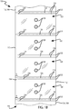
- Figs. 1A-1D illustrates schematics of various embodiments of flexible structures.
- the flexible structure may be formed in a variety of manners such as flexible structure 1040 in shown in Fig. 1A , flexible structure 1042 shown in Fig. 1B , flexible structure 1044 shown in Fig. 1C , or flexible structure 1046 shown in Fig. 1D .
- the flexible structure such as a multi-layer/ply web 100 of film, for inflatable cushions is provided.
- the web includes a first film layer 105 having a first longitudinal edge 102 and a second longitudinal edge 104, and a second film layer 107 having a first longitudinal edge 106 and a second longitudinal edge 108.
- the second web layer 107 is aligned to be over lapping and can be generally coextensive with the first web layer 105 (as shown in Figs. 1A-1D ), i.e., at least respective first longitudinal edges 102,106 are aligned with each other and/or second longitudinal edges 104,108 are aligned with each other.
- the layers can be partially overlapping with inflatable areas in the region of overlap.
- the layers may be joined to define a first longitudinal edge 110 and a second longitudinal edge 112 of the film 100.
- the first and second web layers 105,107 can be formed from a single sheet of web material, a flattened tube of web material with one edge slit, or two sheets of web material.
- the first and second web layers 105,107 can include a single sheet of web material that is folded to define the joined second edges 104,108 (e.g., "c-fold film").
- the first and second web layers 105,107 can include a tube of web material (e.g., a flatten tube) that is slit along the aligned first longitudinal edges 102,106.
- the first and second web layers 105,107 can include two independent sheets of web material joined, sealed, or otherwise attached together along the aligned second edges 104, 108.
- the web 100 can be formed from any of a variety of web materials known to those of ordinary skill in the art. Such web materials include, but are not limited to, ethylene vinyl acetates (EVAs), metallocenes, polyethylene resins such as low density polyethylene (LDPE), linear low density polyethylene (LLDPE), and high density polyethylene (HDPE), and blends thereof. Other materials and constructions can be used.
- EVAs ethylene vinyl acetates
- LDPE low density polyethylene
- LLDPE linear low density polyethylene
- HDPE high density polyethylene
- the disclosed web 100 can be rolled on a hollow tube, a solid core, or folded in a fan folded box, or in another desired form for storage and shipment.
- the web 100 can include a series of transverse seals 118 disposed along the longitudinal extent of the web 100.
- Each transverse seal 118 extends from the longitudinal edge 112 towards the inflation channel 114, and in the embodiment shown, toward the first longitudinal edge 110.
- Each transverse seal 118 has a first end 122 proximate the second longitudinal edge 112 and a second end 124 spaced a transverse dimension d from the first longitudinal edge 110 of the film 110.
- a chamber 120 is defined within a boundary formed by the longitudinal seal 112 and pair of adjacent transverse seals 118.
- Each transverse seal 118 embodied in Figs. 1A-D is substantially straight and extends substantially perpendicular to the second longitudinal edge 112. It is appreciated, however, that other arrangements of the transverse seals 118 are also possible. For example, in some embodiments, the transverse seals 118 have undulating or zigzag patterns.
- the transverse seals 118 as well as the sealed longitudinal edges 110,112 can be formed from any of a variety of techniques known to those of ordinary skill in the art. Such techniques include, but are not limited to, adhesion, friction, welding, fusion, heat sealing, laser sealing, and ultrasonic welding.
- An inflation region such as a closed passageway, which can be a longitudinal inflation channel 114, can be provided.
- the longitudinal inflation channel 114 as shown in Figs. 1A-D , is disposed between the second end 124 of the transverse seals 118 and the first longitudinal edge 110 of the film.
- the longitudinal inflation channel 114 extends longitudinally along the longitudinal side 110 and an inflation opening 116 is disposed on at least one end of the longitudinal inflation channel 114.
- the longitudinal inflation channel 114 has a transverse width D.
- the transverse width D is substantially the same distance as the transverse dimension d between the longitudinal edge 110 and second ends 124. It is appreciated, however, that in other configurations other suitable transverse width D sizes can be used.
- the second longitudinal edge 112 and transverse seals 118 cooperatively define boundaries of inflatable chambers 120.
- the inflatable chambers 120 may further include intermediate seals 128.
- the intermediate seals 128 may seal the 105, 107 to one another at intermediate areas in the chamber 120. As shown in Figs. 1A-D , opposing intermediate seals 128 are transversely aligned across the chamber 120.
- the intermediate seals 128 create bendable lines that allow for a more flexible web 100 that can be easily bent or folded. Such flexibility allows for the film 100 to wrap around regular and irregular shaped objects.
- the intermediate seal 128 may include a partial seal 131.
- the partial seal 131 may extend transversely across chamber 120.
- the partial seal 131 may extend longitudinally or in any other direction across the chamber 120 as well in or in the alternative.
- the partial seal 131 may broaden to define seal section 129 which may also be an inner portion. Seal section 129 may have a larger area with respect to the area of partial seal 131. The larger partial seal 131 may reduce the thickness of the web 100 when inflated.
- the seal section 129 may be a seal wherein the layers 105,107 are attached to one another.
- the seal section 129 may be a section where narrow seals such as a continuation of seal 131 define the seal section 129.
- the seal section 129 may be an area where a seal such as partial seal 131 encloses a section of unattached layers 105, 107.
- a solid seal across seal section 129 (i.e. where the layers 105, 107 are attached) may form a stiffer section of the web 100.
- a non-solid seal across seal section 129 may be a more flexible web 100.
- the patial seal 131 may have include a transition.
- the transition in one example may form a gusset 127.
- the gusset may have a width that is wider than the seal portion 129.
- the seal portion 129 may have a width of J.
- the gusset 127 may widen from width J to 11 ⁇ 2 times wider to 10 times wider.
- the gusset 127 may be 5 times wider.
- the gusset may then narrow again to width K above and below the transition area.
- the gusset 127 may widen to the entire width of the transition area and then narrow back to width J as the partial seal 131 continues.
- the gusset 127 may be concave as viewed from the chamber 120. This may allow the transition to be gradual or not sharp. The gradual transition may reduce stresses at the seal section 129. A sharp transition would be a stress riser such as if the seal section 129 and the seal portion 131 was 90° angle.
- seal section 129 may be circular, oval, triangular, or any other shape. As shown in Fig. 1E the seal section 129 may be a circle.
- a series of lines of weaknesses 126 is disposed along the longitudinal extent of the film and extends transversely across the first and second web layers of the film 100.
- Each transverse line of weakness 126 extends from the second longitudinal edge 112 and towards the first longitudinal edge 110.
- Each transverse lines of weakness 126 in the web 100 is disposed between a pair of adjacent chambers 120.
- each line of weakness 126 is disposed between two adjacent transverse seals 118 and between two adjacent chambers 120, as depicted in Figs. 1A-D .
- the transverse lines of weakness 126 facilitate separation of adjacent inflatable cushions 120.
- the transverse lines of weakness 126 can include a variety of lines of weakness known by those of ordinary skill in the art.
- the transverse lines of weakness 126 include rows of perforations, in which a row of perforations includes alternating lands and slits spaced along the transverse extent of the row. The lands and slits can occur at regular or irregular intervals along the transverse extent of the row.
- the transverse lines of weakness 126 include score lines or the like formed in the web material.
- the transverse lines of weakness 126 can be formed from a variety of techniques known to those of ordinary skill in the art. Such techniques include, but are not limited to, cutting (e.g., techniques that use a cutting or toothed element, such as a bar, blade, block, roller, wheel, or the like) and/or scoring (e.g., techniques that reduce the strength or thickness of material in the first and second web layers, such as electro magnetic (e.g., laser) scoring and mechanical scoring).
- cutting e.g., techniques that use a cutting or toothed element, such as a bar, blade, block, roller, wheel, or the like
- scoring e.g., techniques that reduce the strength or thickness of material in the first and second web layers, such as electro magnetic (e.g., laser) scoring and mechanical scoring.
- the uninflated web 100 can be a bulk quantity of supply, uninflated material.
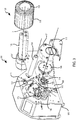
- the bulk quantity of uninflated material may be a roll of the material 134 as illustrated in Figs 2 and 3 .
- the web 100 may be rolled around an inner support tube 133.
- sealing device 101 may include handling elements, with each of the handling elements including film supporting portions.
- the support portions may support and direct an inflatable web of film in a longitudinal direction along a path.
- the handling elements may include a supply support element 136 that supports a supply 134 of the web 100 in an uninflated state.
- An inflation mechanism may be operable to inflate the web with a fluid by directing the fluid between superimposed plies 105, 107 of the web 100.
- a sealing mechanism may be operable to seal the plies 105, 107 together to seal the fluid therein.
- Two of the film supporting portions may be angled and extend in non-parallel directions with respect to one another and transverse to the longitudinal direction. The position of the two film supporting portions may cause a difference in tautness in two portions of the web disposed transversely of each other in a same longitudinal location along the path.
- the inflation and sealing device 101 may include a bulk material support 136.
- the bulk quantity of uninflated material may be supported by the bulk material support 136.
- the bulk material support may be a tray operable to hold the uninflated material, which tray can be provided by a fixed surface or a plurality of rollers for example. To hold a roll of material the tray may be concave around the roll or the tray may convex with the roll suspended over the tray.
- the bulk material support may include multiple rollers which suspend the web.
- the bulk material support may include a single roller that accommodates the center of the roll of web material 134. As illustrated in Figs.
- the roll of the material 134 may be suspended over the bulk material support 136, such as a spindle passing through the core 133 of the roll of the material 134.
- the roll core is made of cardboard or other suitable materials.
- the material support 136 may rotate about an axis Y.
- the web 100 may be suspended over a guide 138 after being pulled off of the supply of uninflated material (e.g., roll 134).
- the guide may provide support to the web 100 upon a transition from the bulk quantity of uninflated material to the sealing and inflation mechanism 103 discussed in more detail below.
- the guide may be a stationary rod extending from a support member 141.
- the guide 138 may be a roller that extends from the support member 141.
- the guide 138 may have an axis X around which the guide 138 rotates.
- the guide 138 or the axis X may extend generally perpendicularly from the support member 141.
- the guide 138 directs the web 100 away from the bulk quantity of uninflated material (e.g.
- the guide may maintain alignment with the sealing and inflation mechanism despite these changes, and preferably with the upstream end of inflation tip 142.
- the guide 138 can be configured to limit the material 134 from sagging between the inflation nozzle 140 and roll 134, and can help maintain any desired tension in the web 100 of the material.
- the inflation and sealing device 101 may include a support member 141.
- the support member 141 may include a base member 183 and a vertical member 186.
- the vertical member 186 may locate the inflation and sealing assembly 103, guide 138, and material support 136 relative to one another.
- the vertical member may be a flat wall. In various embodiments, the vertical member may have a verity of shapes that may extend in various directions.
- the vertical member 186 may be a single component which 103, 138 and 136 all attach to. In this manner the various components the inflation and sealing assembly 103, guide 138, and material support 136 may have tolerances relative to one another based on the tolerances in the formation of the single component. This may very accurately locate the components relative to one another.
- the vertical member 186 and the base member 183 may be a single component. For example, a bent piece of steel may form the vertical member 186 the base member 183.
- the material support 136 may extend from the support member 141 at an angle different than the angle from which guide 138 extends from the support member 141.
- guide 138 may extend from the support member 141 generally perpendicularly, whereas the material support 136 may extend from the support member 141 non-perpendicularly.
- neither the guide 138 nor the material support 136 may extend from the support member 141 perpendicularly.
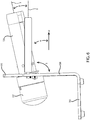
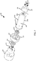
- Fig. 4 illustrates a view of the inflation and sealing device 101 along axis Y.
- the material support 136 is shown on its end, but the length of the guide 138 is shown in an isometric view illustrating an angular difference between the two.
- the axis Y extends up compared to axis X.
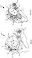
- Fig. 5 illustrates a front view showing the end of guide 138 but a bottom isometric view of material support 136.
- the axis Y extends up compared to axis X.
- axes Y and X may be skew axes (i.e. the axes may be neither parallel nor intersecting).
- the relative position of these axes indicates the relative position of the material support 136 and the guide 138.
- the material support 136 and the guide 138 may rotate around axes Y and X respectively.
- the axis X may be perpendicular to the support member 141 with Y being non-perpendicular to the support member 141.
- axis Y or the material support 136 may be positioned at an angle ⁇ relative to the front wall 139 of the support member 141.
- the angle ⁇ may be greater than 90°.
- ⁇ may be 70° to 140°.
- ⁇ may be about 100°.
- the material support 136 and the guide 138 may be attached to different surfaces or at different angles, such as both pointed upwards with respect to the front wall 139 or both pointed down words with respect to the front wall.
- the angle between axis X and axis Y may be ⁇ . ⁇ may be measured rotationally about the longitudinal path of the web 100.
- axis X and axis Y extend transversely from the longitudinal path with a rotational variance about that path.
- This same system of measurement may be used with respect to other components as well (e.g. axis W)
- ⁇ may be an angle between the axes that ranges from about 5° to about 70°.
- ⁇ may be an angle between the axes that ranges from about 10° to about 45°.
- the web 100 may travel through the inflation and sealing device 101 along path E.
- the film path E extends along the nozzle 140.
- An axis Z is located where the film path E follows the nozzle 140.
- the direction that nozzle 140 points is the same direction axis Y points. For example if nozzle 140 points up (e.g. away from base 183) then axis Y points up. If nozzle 140 points down (e.g. toward base 183) then axis Y points down.
- the path may include a plurality of direction changes for the flexible structure 100 with each direction change characterized by a plurality of curves that describes the direction change of the flexible structure and a transversely extending central axis defined by geometry of each of the curves. In some embodiments, the path may be generally straight having no or few direction changes for flexible structure 100 through the device.
- the web 100 may pass above the guide 138.
- the material support 136 and axis Y may be angled with respect to guide 138 such that the material support 136 and axis Y point in the same direction as the web 100 passes over guide 138. If web 100 passes over guide 138 then the material support 136 may point up relative to the guide 138. If web 100 passes under then guide 138, then the material support 136 may point down relative to guide 138.
- the web 100 passes through the inflation and sealing assembly 103 and extends away from the inflation and sealing device 101 in a transverse direction which is perpendicular to longitudinal direction A in which the web 100 exits the inflation and sealing device 101.
- An axis W may be aligned at the pinch area 176 and extend in the transverse direction away from the inflation and sealing device 101.
- the angle ⁇ between the axis W and the axis Y may be an angle between the ranges from about 5° to about 70°.
- the angle ⁇ between W and the axis Y may be an angle between about 10° to about 45°.
- the angle may be viewed in the longitudinal direction such as from the front of the inflation and sealing device 101 such as shown in figure 6 .
- axes Y and X may be parallel, for example both extending though the support member 141 perpendicularly, both may extend downwardly, or both may extend upwardly. As indicated above Y and X may be non-parallel with both extending downwardly, or both extending upwardly.
- the angled supporting elements may be positioned relative to one another such that the web travelling along the path is more taught on one transverse side of the handling element than the other.
- the web 100 when the web 100 is removed from the material support 136 and is positioned at an angle different from the guide 138, the web 100 includes a slight twist as it is removed from the bulk quantity of uninflated material (e.g. roll 134) and realigned over and in contact with guide 138.
- the web 100 may roll off of material support 136 tangentially and thereby forming a plane (or a surface that approximates a plane tangential with the surface of the roll 134) that is parallel with the axis of material support 136.
- the web 100 may also engage guide 138 tangentially forming a different plane (or approximating a different plane tangent with the guide 138).
- the web may merely reflect tangential planes as if it maintained tangential contact with the material support 136 or guide 138 even if in practice there is tension on one transverse end of the web 100 and slack on the other transvers end of the web 100.
- the web 100 may realign or twist slightly between the material support 136 and guide 138. This realignment of the web 100 may cause this slight twist which may affect the way that the web 100 contacts guide 138.
- the slight twist causes the web 100 to have greater pressure against the guide 138 proximate to the connection between guide 138 and the support member 141.
- the web 100 may have lesser pressure and less tension on the end of guide 138 that is distal to the connection between guide 138 and the support member 141. This configuration of contact between web 100 and guide 138 aids in maintaining alignment of the web toward the sealing mechanism and limiting the tendency of the web 100 to drift off the end of guide 138 that is distal of the support member 141.
- the end of the material support 136 can have a tendency to sag under weight, such as under the weight of a roll of material 134 being mounted thereon.
- the material support 136 and or axis Y tends to deflect downwardly when the roll of material 134 is mounted thereon. In this position the opposite effect to the one discussed above occurs.
- the web 100 may contact the guide 138 with greater pressure on the end of the guide 138 that is distal to the support member 141.
- the side of the guide 138 that is proximate to the support member 141 may have less pressure between the guide 138 and the web 100 as compared to the distal end of guide 138.
- web 100 may tend to drift off the guide 138, become un-aligned with the sealing and inflation mechanism, or acquire slack between the roll of material 134 and the sealing and inflation mechanism.
- structuring the material support 136 with an angle greater than the guide 138 as measured upwardly from the support member 141 e.g. see Fig. 6
- the sag in the material support 136 and the tension issues with the guide 138 may be overcome, thereby improving the intake of web 100 into the sealing and inflation mechanism.
- the nozzle 140 may inflate web 100 not only at a transverse edge but may engage an inflation channel located at any transverse distance between the longitudinal edges; i.e., the inflation and sealing device 101 fills a central channel with chambers on both transverse sides of the inflation channel.
- the web 100 may roll off of material support 136 and over guide 138 in a manner that aligns such a central inflation channel with the nozzle 140.
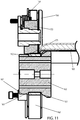
- the material support 136 may include a spindle 200.
- the spindle 200 may be axially aligned along axis Y with a motor 220.
- the motor 220 and the spindle 200 may be attached via a bulkhead connector 222.
- the bulk head connector 222 may have a mounting surface 223.
- the mounting surface may attach to the backside of the support member 141 such that the motor 220 may be positioned on one side and the spindle 200 may be positioned on the other side as illustrated in Fig. 6 .
- the mounting surface 223 may form an angle with axis Y such that axis Y is not perpendicular thereto.
- Fig. 6 shows mounting surface 223 as parallel with vertical plate 184.
- ⁇ represents the angle between mounting surface 223 and Y.
- the mounting surface 223 may be angled such that as it attaches to the back side of the support member 141, it tilts the spindle 200 and motor 220 relative to the support member 141.
- An example of this structure is shown in Fig. 6 with the angle ⁇ which may also represent the angle between mounting surface 223 and the axis Y.
- Spindle 200 may be supported within the bulk head connector 222 by bearings 214 and 224. The bearings 214,224 may allow the spindle 200 to be rotatable independent of the bulkhead connector 222 and ultimately the support member 141, to which the bulkhead connector 222 attaches.
- the spindle may be supported on a shaft, surface bearings, or by the motor directly.
- the spindle 200 may be locked into place on the bulk head 222 with clip 226.
- Cover 228 and bulk head connector 222 may form an enclosure around motor 220.
- the spindle 200 may include two sections, a body portion 202 and a tip portion 204.
- the body portion 202 and the tip portion 204 may be formed of different materials. 6.
- the spindle 200 preferably has core support portions 206, which are outwardly facing surfaces spaced circumferentially about axis Y from each other to provide radially recessed areas 208 therebetween.
- the core support portions 206 protrude radially from the axis Y higher than the surfaces of the spindle 200 in the radially recessed areas 208.
- the core support portions can collectively define and be positioned along a phantom cylindrical surface that will correspond closely to the interior, hollow, surface within a supply roll 134.
- the core support portions can be arranged in other shapes.
- the core support portions 206 can be curved circumferentially along this phantom cylindrical surface or can be flat or have other shapes.
- the recessed areas 208 are positioned radially inward of the phantom cylinder, so that they entirely or in large part do not contact the interior of a supply roll mounted on the spindle 200.
- the recessed areas 208 have substantially flat surfaces in the embodiment shown, but other configurations can be used.
- the support element may include a major radius and minor radius.
- the major radius may be the outer most structural portion of the support element.
- the minor radius may be the smallest radius of the recessed areas 208.
- the minor radius at a center point between core support portions may depend upon the length of the circumferential portion of the core support portions, the number of support portions, and the shape of the recessed areas.
- the minor radius may be 1/2 of the major radius of the core support portions (e.g. assuming an equilateral triangle with core support portions having negligible length and the recessed area having a flat surface shape.)
- the minor radius may be less than 1/2 of the major radius providing additional clearance for insertion into a deformed supply roll.
- the minor radius may greater than 1/2 of the major radius providing additional strength for supporting the supply roll.
- the core support portions may have a sufficient circumferential length so as to not cut into the roll core but instead support the roll core while also being usable with a roll core having collapsed portions.
- Each of the core support portions 206 may form a contiguous part of the outer surface of the support element (e.g. spindle 200) gripping elements 210 may extend from the out surface.
- the core support portions 206 may be the largest radius of the support element (e.g. spindle 200).
- the core support portions may be separated by the recessed features such that core support portions 206 occur every 10-120° around the axis of the support element (e.g. spindle 200).
- the core support portions 206 may be located every 120°.
- the recessed areas 208 lie below the phantom cylinder 207, and the core support portions 206 generally follow the phantom cylinder 207, although other shapes can be used.
- the spindle 200 may be generally triangular in shape having three core support portions 206, but can alternatively have four, five, or more core support surfaces, and the core support portions can be evenly or unevenly distributed circumferentially about the spindle.
- the spindle 200 may have an axial cross section that forms a triangle.
- the core support surfaces 206 preferably extend substantially axially with respect to the spindle (transversely with respect to the material path or machine direction in the embodiment of Fig. 2 ) to help in sliding a web roll core 133 on and off the spindle.
- the spindle By providing the recessed areas between the core support portions 206 provides the spindle with a discontinuous support surface in which the contact area it has with a core 133 of a supply web roll 134 can be reduced compared to traditional, continuous-surface cylindrical spindles. This reduces the friction between the spindle 200 and core 133, allowing the core 133 to be more easily inserted and slid off from the spindle 200. Additionally, as is common and can be seen in Fig. 4 , the core 133 can be deformed, such as by damage during shipping of the supply material roll 134. Damaged, out-of-round cores can be very difficult or impossible to insert onto a fully cylindrical spindle.
- the recessed areas 208 on the discontinuous spindle surface can accommodate deformations of the core 133 that extend inwardly between the core support portions 206, allowing dented or flattened cores to remain useable.
- the core support surfaces 206 a,b,c or a plurality of grip elements 210 which extend from the core support surfaces 206 a,b,c may contacts or occupy only a fraction of the outer core surface circumference.
- the plurality of contacts may contact a finite number of points within an internal surface of a hollow tube onto which the web of material is rolled.
- the plurality of grip elements 210 may extend beyond the generally cylindrical shape shown by line 207.
- the plurality of contacts may form a larger diameter around the spindle than the size of the inner diameter of inner support tube 133. This structure would allow the plurality of contacts to engage in an interference fit with the core 133 while the minimized outer cylindrical surface segments 206 a,b,c minimize other contact within the core 133.
- the grip elements 210 are biased outwardly and are resiliently movable inwardly into the spindle 200. Such bias can be provided by springs within the spindle.
- the outer surface of the grip elements 210 can be spherical, conical, or have another shape that preferably facilitates sliding of the core 133 during loading and unloading on or from the spindle, and that grips the inner surface of the core 133 during use, to help transfer torque from the spindle to the roll, and preferably from the brake 137, described below.
- a chamfer 204 at the end of tip portion 204 may additionally reduce the effort of inserting spindle 200 into the inner support tube 133.
- the support element 136 may be connected with a brake 137.
- the brake 137 may prevent or inhibit bunching up of the web material 100 and maintain a desired tension in the web material 100 as it is unwound from the roll 134 and as it is fed onto and/or into the inflation and sealing mechanism.
- the brake 137 may prevent or inhibit release of the bulk uninflated material from the support 136.
- the brake 137 may inhibit the free unwinding of the roll 134.
- the brake may also assure that the roll 134 is unwound at a steady and controlled rate.
- the brake 137 may be provided by any mechanism that provides control.
- a spring-loaded leather strap or other friction mechanism can be used as a drag brake on the bulk material support 136.
- the brake 134 may be an electric motor or other actuator used to provide resistance to the rotation of the bulk material support 136 as the roll 134 is unwound.
- the support element 136 is spindle 200 which is axially connected to a brake which may operate as a resistance mechanism.
- the resistance mechanism resists rotation of the support element 136 (e.g. spindle 200).
- the resistance mechanism may be motor 220 which controls rotation of the spindle 200, thereby controlling advancement of the web 100 by either positively driving rotation of spindle 200 or retarding the rotation of spindle 200.
- the brake can also increase tension on the twisted web proximal to the support member 141, maintaining proper alignment with the inflating/sealing mechanism.
- the inflation and sealing device 101 is configured for continuous inflation of the web 100 as it is unraveled from the roll 134.
- the roll 134 preferably, comprises a plurality of chain of chambers 120 that are arranged in series.
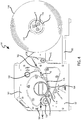
- the inflation opening 116 of the web 100 is inserted around an inflation assembly, such as an inflation nozzle 140.
- the web 100 is advanced over the inflation nozzle 140 with the chambers 120 extending transversely with respect to the inflation nozzle 140 and outlet 146.
- the outlet 146 which can be disposed on a radial side and/or the upstream tip of the nozzle 140, for example, directs fluid from nozzle body 144 into the chambers 120 to inflate the chambers 120 as the web 100 advances along the material path "E" in a longitudinal direction "A".
- the inflated web 100 is then sealed by a sealing drum 166 in the sealing area 174 to form a chain of inflated pillows or cushions.
- the side inflation area 168 in the embodiment of Fig. 3 is shown as the portion of the inflation and sealing device 101 along the path "E" adjacent the side outlets 146 in which air from the side outlets 146 can inflate the chambers 120.
- the inflation area 168 is the area disposed between the inflation tip 142 and entry pinch area 176, described below.
- the web 100 is inserted around the inflation nozzle 140 at the inflation tip 142, which may be disposed at the forward-most end of the inflation nozzle 140.
- the inflation nozzle 140 inserts fluid, such as pressured air, along fluid path B into the uninflated web material through nozzle outlets, inflating the material into inflated pillows or cushions 120.
- the inflation nozzle 140 can include a nozzle inflation channel that fluidly connects a fluid source with the nozzle outlets. It is appreciated that in other configurations, the fluid can be other suitable pressured gas, foam, or liquid.
- Figs. 3 , 9 , 10 , and 11 illustrates a various view of the inflation and sealing device 101.
- the fluid source can be disposed behind the support member 141 having a horizontal plate 183 and vertical plate 184 or other structural support for the nozzle and sealing assemblies, and preferably behind the inflation nozzle 140.
- the fluid source is connected to and feeds the fluid inflation nozzle conduit 143.
- the web 100 is fed over the inflation nozzle 140, which directs the web to the inflation and sealing assembly 103.
- the web 100 is advanced or driven through the inflation and sealing device 101 by a drive mechanism, such as by a driver or sealing drum 166 or the drive roller 160, in a downstream direction along a material path "E".
- the nozzle, blower sealing assembly, and drive mechanisms, and their various components or related systems may be structured, positioned, and operated as disclosed in any of the various embodiments described in for example U.S. Patent Application No. 13/844,741 . Each of these embodiments may be incorporated to the inflation and sealing device 101as discussed herein.
- the sealing drum 166 includes heating elements, such as thermocouples, which melt, fuse, join, bind, or unite together the two web layers 105,107, or other types of welding or sealing elements.
- the web 100 is continuously advanced through the sealing assembly along the material path "E" and past the sealing drum 166 at a sealing area 174 to form a continuous longitudinal seal 170 along the web by sealing the first and second web layers 105,107 together, and exits the sealing area at an exit pinch area 178.
- the exit pinch area 178 is the area disposed downstream the entry pinch area 164 between the belt 162 and the sealing drum 166, as shown in Fig.
- the sealing area 174 is the area between the entry pinch area 164 and exit pinch area 178 in which the web 100 is being sealed by the sealing drum 166.
- the longitudinal seal 170 is shown as the phantom line in Figs. 1A-D .
- the longitudinal seal 170 is disposed a transverse distance from the first longitudinal edge 102,106, and, most preferably, the longitudinal seal 170 is disposed along the mouths 125 of each of the chambers 120.
- the sealing drum 166 is arranged above the belt 162.
- the drive roller 160 is preferably positioned downstream the feed roller 158 and tension roller 156 with the sealing drum 166 there between.
- the sealing drum 166 is disposed such that a portion of the sealing drum 166 vertically overlaps the feed roller 158, tension roller 156, and drive roller 160 so that the belt 162 is deformed at the sealing area 174 to have a generally U-configuration.
- Such configuration increases the tension of the belt 162 at the sealing area 174, and facilitates the pinching of the web 100 between the sealing drum 166 and the belt 162 at the sealing area 174.
- the inflation and sealing assembly 103 configuration described also reduces the amount of contact of the web 100 during sealing, which reduces bending of the inflated web. As shown in Fig. 4 , the contact area is the sealing area 174 between the entering pinch area 164 and exiting pinch area 178.
- the web 100 enters the sealing assembly at the entry pinch area 176 at an angle sloping downward with respect to the horizontal. Additionally, the web 100 exits the sealing area 174 at an angle sloping upward with the respect to the horizontal so that the web 100 is exiting facing upwards toward the user.
- the inflation and sealing device 101 allows for easy loading and extracting of the web as well as easy access to the web.
- the inflation and sealing device 101 can be positioned below eye level, such as on a table top, without the need of a high stand.
- the sloping downward intake and sloping upward outtake of the web 100 from the sealing assembly provides for the material path "E" to be bent at an angle ⁇ between the entry pinch area 176 and the exit pinch area 174 (the entry pinch area 176 and exit pinch area 174 are further described below).
- the angle ⁇ between the entry pinch area 176 and exit pinch area 174 is, for example, at least about 40° up to at most about 180°.
- the angle ⁇ may be about 90°.
- Other entry and exit angles can be employed as known in the art in alternative embodiments.
- the sealing assembly may be protected by a removable cover.
- the belt mechanism e.g. belt 162, tension roller 156, and feed roller 158 may also include a removable cover 173. This allows for a user to easily remove the web or clear up or fix jams within the machine.
- one or more of the elements of inflation and sealing device 101 may drive web 100 through the system.
- the sealing drum 166 may be connected to a motor which rotates it in a direction "F".
- other elements may also drive the system, such as roller 160.
- roller 160 is indicated as a drive roller; however, it may be noted that roller 160 may be either an idler roller or an active drive roller.
- roller 160 may be connected to the same motor or the same drive mechanism associated with the sealer drum 166 that causes the drum to rotate.
- the sealing drum 166 may be passive (e.g. an idler) or actively driven by a motor. In one example, the sealing drum 166 may be passive and merely be rotated in response to the advancing web 100 or belt 162.
- the inflation and sealing device can have more than one belt.
- one belt may drive the various rollers and a second belt may pinch the web against the sealing drum.
- the inflation and sealing device may have no belts.
- the sealing drum may pinch the web against a stationary platform and drive the web thorough the inflation and sealing device at the same time. Additional description and embodiments of such structures may be disclosed in U.S. Patent Nos. 8,061,110 and 8,128,770 and Publication No. 2011/0172072 .
- the inflation and sealing assembly 103 includes a plurality of post-seal control elements.
- the post-seal control element may be a movable or stationary surface, a roller, or any device that can contact the belt 162 or the web 100.
- a post-seal control element can include roller 160 as discussed above.
- the roller 160 supports the web 100 exiting from the inflation and sealing assembly 103 and may be operable to guide the belt.
- the roller 172 may also be a post-seal control element.
- a single post-seal control element such as roller 160 as depicted in embodiments disclosed in the incorporated references (see e.g. 13/844,741 ).
- a post-seal control element e.g. roller 172
- a post-seal control element can be disposed directly above a post-seal control element (e.g. roller 160).
- the two post-seal control elements pinch or press the web 100 so that the belt 162 abuts one or both of the surfaces of the elements.
- This area may be a holding region operable to maintain contact between sealed portion of the film until the seal is fully formed.
- rollers 160, 172 are disposed immediately downstream of the heating drum (or other heating mechanism in other embodiments), they provide a cooling region 179 disposed between two rollers 160,172.
- Roller 160 in this embodiment acts as a principle cooling roller, since the sealed and cooling film is drawn around this roller 160.
- Pinch roller 172 maintains the web in contact with the principle cooling roller 160 to help maintain the pressure between the two film layers as the seal cools to support the seal and surrounding area mechanically.
- roller 160 In embodiments, such as the one shown, in which the belt 162 extends around roller 160, the outer surface of this roller remain substantially stationary with respect to the web 100, further helping support the seal in its delicate state before it has cooled sufficiently.
- Roller 160 is typically made of a hard and tough material, such as steel or aluminum, to withstand the pressures and heat from the belt 162, although a plastic or other material could be used in some embodiments.
- the Roller 160 may be formed from a non-stick material or coated with a non-stick coating such as polytetrafluoroethylene (PTFE).
- PTFE polytetrafluoroethylene
- the post-seal control element such as roller 172 may have a larger-diameter area 171 opposing the belt than in adjacent parts of pinch roller 172.
- This annular ridge 171 allows contact against the web 100, while an adjacent smaller-diameter portion of roller 172 can remain out of contact therewith to help prevent sticking to the hot web.
- the roller 172 may be biased against the belt 162, web 100, and roller 160 by a spring-loaded tensioner 169. The tension provided by the tensioner 169 may further hold the seal closed by the post-seal control element, and can allow the pinch roller 172 to be lifted off the web when needed.
- the pinch roller is preferably made of, or has a surface of, a non-stick or low adhesion material such as polytetrafluoroethylene (PTFE) or other suitable material as discussed below.
- PTFE polytetrafluoroethylene
- the post-seal control element such as roller 160 may include a recessed annular surface 163. The recessed annular surface 163 may receive the belt 162.
- roller 160 can have an annular ridge 161 extending proud the belt 162 or outer surface 167 of the roller 160 that supports the belt 162 against the web 100, or that contacts the web 100.
- This ridge 161 can be annular or have another suitable shape and can run around the roller to contact the web 100, preferably transversely adjacent the longitudinal seal on the inflated web 100, such as against the transverse end of the inflated chambers 120 adjacent the longitudinal seal 112.
- the annular ridge 161 contacts the web 100, typically against a transverse side of the inflated chambers 120 where due to the inflated shape, the chambers 120 have a degree of rigidity compared to the uninflated film.
- the elevated ridge provides a bump-off element forcing the web 100 to deflect off the roller 160.
- the annular ridge 161 is a second surface that causes the web to bend.
- the bend may cause a portion of the web 100, located in the lateral direction relative to a first portion of the web 100 that is pressed between the first post-seal control element (e.g. roller 160) and the second post-seal control element (e.g. roller 172), to not stay in the same plane as the first portion of the web. Forcing different portions of web 100 into different planes may cause the web 100 to unseat, and often unstick, from the belt and/or the roller 160. As such, the annular ridge 161 aids in automatically peeling the web 100 off the post-seal control elements. While described with respect to a roller, alternative embodiments can have a stationary ridge provided adjacent the roller 160 to guide the web off the cylinder.
- non-stick materials may mitigate this issue.
- one or both post-seal control elements may be made from of coated with polytetrafluoroethylene (PTFE).
- PTFE polytetrafluoroethylene
- Other non-stick materials may also be used including anodized aluminum, ceramic, silicone, or like non-stick/low-adhesion materials. However, even these materials may still be coated with polytetrafluoroethylene (PTFE).
- the inflation and sealing device 101 further includes a cutting assembly 186 to cut the web off the inflation nozzle when an inflation channel that receives and is closed around a longitudinal inflation nozzle 140 is used.
- the cutting assembly may also be structured, provided, or included in accordance with the various embodiments described by the incorporated references discussed above.
Landscapes
- Engineering & Computer Science (AREA)
- Mechanical Engineering (AREA)
- Manufacturing & Machinery (AREA)
- Making Paper Articles (AREA)
- Shaping By String And By Release Of Stress In Plastics And The Like (AREA)
- Buffer Packaging (AREA)
- Lining Or Joining Of Plastics Or The Like (AREA)
- Orthopedics, Nursing, And Contraception (AREA)
Claims (15)
- Bahnaufblasvorrichtung (101), umfassendeinen Aufblasmechanismus (140), der betrieben werden kann, um die Bahn (100) mit einem Fluid aufzublasen, indem er das Fluid zwischen übereinanderliegenden Lagen (105, 107) der Bahn leitet;einen Dichtungsmechanismus (168), um die Lagen miteinander abzudichten, um das Fluid darin abzudichten;ein erstes Nachabdichtungssteuerelement (160), das einen Haltebereich beinhaltet, an dem das Element betrieben werden kann, um die abgedichteten Lagen zusammenzuhalten, wobei das erste Nachabdichtungssteuerelement eine erste Oberfläche aufweist, gegen die die abgedichteten Lagen stromabwärts von dem Dichtungsmechanismus zusammengehalten werden; und dadurch gekennzeichnet, dass das erste Nachabdichtungssteuerelement (160) ein Materialfreigabeelement (161) beinhaltet, das ein an die erste Oberfläche angrenzender Grat ist und betrieben werden kann, um die abgedichteten Lagen von dem ersten Nachabdichtungssteuerelement zu lösen, wenn die abgedichteten Lagen den Haltebereich verlassen.
- Vorrichtung nach Anspruch 1, wobei der Haltebereich die abgedichteten Lagen zusammendrückt.
- Vorrichtung nach Anspruch 1, wobei der Dichtungsmechanismus ein Heizelement beinhaltet, das die Lagen erwärmt, um die Dichtung zu bilden.
- Vorrichtung nach Anspruch 1, wobei der Haltebereich einen Bereich (179) bereitstellt, der zum Kühlen der Dichtung zum Verbessern der Dichtung zwischen den Dichtungslagen betrieben werden kann.
- Vorrichtung nach Anspruch 1, wobei das erste Nachabdichtungssteuerelement Polytetrafluorethylen (PTFE) umfasst.
- Vorrichtung nach Anspruch 1-5, ferner umfassend ein zweites Nachabdichtungssteuerelement (172) mit einer gegenüberliegenden Oberfläche, die die Bahn an einer Stelle entlang des Haltebereichs berührt und die abgedichteten Lagen gegen das erste Nachabdichtungssteuerelement drückt, das einen ersten Kontakt für einen ersten Abschnitt der abgedichteten Lagen bildet.
- Vorrichtung nach Anspruch 6, wobei das Materialfreigabeelement eine zweite Oberfläche angrenzend an die erste Oberfläche beinhaltet und positioniert ist, dass, wenn die abgedichteten Lagen zwischen dem ersten Nachabdichtungssteuerelement und dem zweiten Nachabdichtungssteuerelement komprimiert werden, die Lagen veranlasst werden, sich angrenzend an dem ersten Kontakt zu biegen.
- Vorrichtung nach Anspruch 6, wobei mindestens eine von der ersten Oberflächen des ersten Nachabdichtungssteuerelements oder der gegenüberliegenden Oberfläche des zweiten Nachabdichtungssteuerelements eine kontinuierlich gebogene Oberfläche ist.
- Vorrichtung nach Anspruch 7, wobei die zweite Oberfläche des Materialfreigabeelements durch einen stationären Grat definiert ist, der angrenzend an der ersten Oberfläche positioniert ist.
- Vorrichtung nach Anspruch 7, wobei die zweite Oberfläche des Materialfreisetzungselements durch einen Grat definiert ist, der in Bezug auf die erste Oberfläche hervorvorsteht.
- Vorrichtung nach Anspruch 10, wobei mindestens eines von dem ersten Nachabdichtungssteuerelement und dem zweiten Nachabdichtungssteuerelement eine Rolle beinhaltet.
- Vorrichtung nach Anspruch 10, wobei die erste Oberfläche in Bezug die auf zweiten Oberfläche so positioniert ist, dass ein zweiter Abschnitt der Bahn, der sich in der seitlichen Richtung in Bezug auf den ersten Abschnitt der Bahn befindet, zu einem zweiten Kontakt gezwungen wird, der sich auf einer anderen Ebene oder einem anderen Zylinderdurchmesser als der erste Abschnitt befindet.
- Vorrichtung nach Anspruch 12, wobei das erste Nachabdichtungssteuerelement eine Rolle beinhaltet, und wobei der Grat auf der Seite der Rolle positioniert ist, die konfiguriert ist, um während des Betriebs der Vorrichtung zwischen den gegenüberliegenden Längsgraten der aufblasbaren Bahn positioniert zu sein.
- Vorrichtung nach Anspruch 10, wobei der Grat ein ringförmiger Grat ist, der konfiguriert ist, um die Bahn an einer Stelle zu berühren, wo die Bahn aufgeblasen wird, sodass die Bahn aufgrund des Aufblasens einen Steifigkeitsgrad im Vergleich zu der nicht aufgeblasenen Bahn aufweist, der es dem ringförmigen Grat ermöglicht, die Bahn von dem ersten Nachabdichtungselement abzustoßen, das die Bahn weg von dem ersten und zweiten Nachabdichtungselement ablenkt.
- Vorrichtung nach Anspruch 10, wobei das erste Nachabdichtungssteuerelement Polytetrafluorethylen (PTFE) umfasst und der Grat ein ringförmiger Grat ist, und wobei das Polytetrafluorethylen (PTFE) des ersten Nachabdichtungssteuerelements in Übereinstimmung mit dem ringförmigen Grat arbeitet, um die Kraft zu reduzieren, die erforderlich ist, um die Bahn von dem ersten und zweiten Nachabdichtungselement abzustoßen.
Applications Claiming Priority (4)
| Application Number | Priority Date | Filing Date | Title |
|---|---|---|---|
| US201461944030P | 2014-02-24 | 2014-02-24 | |
| US201461944026P | 2014-02-24 | 2014-02-24 | |
| US201461944515P | 2014-02-25 | 2014-02-25 | |
| PCT/US2015/017402 WO2015127481A1 (en) | 2014-02-24 | 2015-02-24 | Inflatable film handling device |
Publications (3)
| Publication Number | Publication Date |
|---|---|
| EP3110697A1 EP3110697A1 (de) | 2017-01-04 |
| EP3110697A4 EP3110697A4 (de) | 2017-11-29 |
| EP3110697B1 true EP3110697B1 (de) | 2019-03-27 |
Family
ID=53879178
Family Applications (1)
| Application Number | Title | Priority Date | Filing Date |
|---|---|---|---|
| EP15751999.2A Active EP3110697B1 (de) | 2014-02-24 | 2015-02-24 | Vorrichtung zur handhabung von aufblasbarer folie |
Country Status (8)
| Country | Link |
|---|---|
| US (2) | US10500808B2 (de) |
| EP (1) | EP3110697B1 (de) |
| JP (1) | JP6712950B2 (de) |
| CN (1) | CN106232482B (de) |
| BR (1) | BR112016019459B1 (de) |
| HK (1) | HK1232194A1 (de) |
| MX (2) | MX2016011051A (de) |
| WO (1) | WO2015127481A1 (de) |
Families Citing this family (17)
| Publication number | Priority date | Publication date | Assignee | Title |
|---|---|---|---|---|
| US9977423B2 (en) | 2015-12-23 | 2018-05-22 | Pregis Intellipack Llc | Rewind queue feature for protective packaging control |
| JP6466751B2 (ja) * | 2015-03-19 | 2019-02-06 | 株式会社イシダ | フィルムロール支持装置 |
| US10227171B2 (en) | 2015-12-23 | 2019-03-12 | Pregis Intellipack Llc | Object recognition for protective packaging control |
| WO2017172834A1 (en) * | 2016-03-28 | 2017-10-05 | Pregis Innovative Packaging Llc | Idler roller |
| CN205836096U (zh) * | 2016-07-01 | 2016-12-28 | 杭州丙甲科技有限公司 | 缓冲气垫机 |
| JP2021513935A (ja) | 2018-02-14 | 2021-06-03 | プレジス・イノベーティブ・パッケージング・エルエルシー | 包装材料に使用される膨張性クッションを製造するための装置 |
| JP7320519B2 (ja) * | 2018-02-14 | 2023-08-03 | プレジス イノベーティブ パッケージング エルエルシー | 保護用包装部材形成装置 |
| JP7432514B2 (ja) * | 2018-02-14 | 2024-02-16 | プレジス イノベーティブ パッケージング エルエルシー | 包装材料に使用される膨張性クッションを製造するための装置 |
| MX2020008553A (es) * | 2018-02-14 | 2021-01-29 | Pregis Innovative Packaging Llc | Aparato de inflación y sellado que comprende un miembro de guía con un elemento de expansión. |
| CN111902259B (zh) | 2018-02-14 | 2023-04-04 | 普里吉斯创新包装有限责任公司 | 用于形成保护性包装的装置 |
| CN115211636A (zh) | 2018-05-31 | 2022-10-21 | 耐克创新有限合伙公司 | 带有无缝侧壁的流体填充缓冲制品及其制造方法 |
| US11542086B2 (en) * | 2018-08-06 | 2023-01-03 | Better Packages, Inc. | Packaging apparatus for film inflation and method thereof |
| DE102018007549A1 (de) * | 2018-09-24 | 2020-03-26 | Sprick Gmbh Bielefelder Papier- Und Wellpappenwerke & Co. | Antriebsmechanismus für einen Verpackungsmaterial-Strangwickler, Verpackungsmaterial- Strangwickler, gewickeltes Verpackungsmaterial-Polster und Verfahren zum Herstellen desselben |
| EP4021716A1 (de) * | 2019-10-22 | 2022-07-06 | Sealed Air Corporation (US) | Aufblasvorrichtung für aufblasbare bahnen mit gasbewegungsvorrichtungen in reihe |
| IT201900024781A1 (it) * | 2019-12-19 | 2021-06-19 | Officina Bocedi S R L | Macchina per il rivestimento di pallet |
| CN115023341A (zh) * | 2019-12-23 | 2022-09-06 | 普里吉斯创新包装有限责任公司 | 具有幅材控制的充气和密封装置 |
| US11591152B2 (en) * | 2020-12-02 | 2023-02-28 | Michael G. Kaminski | Inflatable packaging vessel for fragile articles |
Family Cites Families (111)
| Publication number | Priority date | Publication date | Assignee | Title |
|---|---|---|---|---|
| US3010267A (en) * | 1959-05-25 | 1961-11-28 | Chicago Carton Co | Carton sealing apparatus |
| US3333395A (en) * | 1964-09-11 | 1967-08-01 | Lee Packaging Machinery Corp | Apparatus for heat-sealing articles between sheets of transparent material |
| US3377773A (en) | 1965-03-26 | 1968-04-16 | Allied Chem | Thermoplastic film packaging apparatus |
| US3487755A (en) * | 1966-04-14 | 1970-01-06 | Union Carbide Corp | Method and device for forming and sealing closures in thermoplastic bags |
| US3660189A (en) | 1969-04-28 | 1972-05-02 | Constantine T Troy | Closed cell structure and methods and apparatus for its manufacture |
| US4017351A (en) | 1975-12-24 | 1977-04-12 | Minnesota Mining And Manufacturing Company | System and device for inflating and sealing air inflated cushioning material |
| US4359361A (en) | 1976-05-27 | 1982-11-16 | The Dow Chemical Company | Impulse sealer |
| US4075818A (en) | 1976-06-04 | 1978-02-28 | The Dow Chemical Company | Impulse sealing apparatus |
| US4215524A (en) | 1979-01-29 | 1980-08-05 | C. R. Bard, Inc. | Membrane packaging machine |
| US4244158A (en) | 1979-03-13 | 1981-01-13 | R. Nelham & Associates Incorporated | Package forming method and apparatus |
| US4269712A (en) * | 1979-05-14 | 1981-05-26 | Cordis Dow Corp. | Hollow fiber separatory element and method of making same |
| US4350003A (en) | 1980-03-13 | 1982-09-21 | Package Machinery Company | Sealing head |
| US4412879A (en) | 1981-11-02 | 1983-11-01 | Ranpak Corp. | Cushioning dunnage apparatus and method |
| US4542771A (en) * | 1984-02-03 | 1985-09-24 | Springs Industries, Inc. | Adjustable anvil for ultrasonic material cutting and sealing apparatus |
| US4560427A (en) * | 1984-12-03 | 1985-12-24 | Branson Ultrasonics Corporation | Ultrasonic seal and cut method and apparatus |
| JP2594793B2 (ja) | 1987-08-03 | 1997-03-26 | エービー テトラパック | 包装容器の製造方法 |
| US4876842A (en) | 1988-01-15 | 1989-10-31 | Minigrip, Inc. | Method of and apparatus for packaging product masses in a form, fill and seal machine |
| GB9121420D0 (en) * | 1991-10-09 | 1991-11-20 | Ag Patents Ltd | Manufacturing infusion packages |
| DE4203435C1 (de) * | 1992-02-06 | 1993-02-25 | Pvt Piepenbrock Verpackungstechnik Gmbh, 4500 Osnabrueck, De | |
| US5427830A (en) | 1992-10-14 | 1995-06-27 | Air Packaging Technologies, Inc. | Continuous, inflatable plastic wrapping material |
| JP3332173B2 (ja) | 1993-07-09 | 2002-10-07 | 日本テトラパック株式会社 | 残留製品除去装置 |
| US5449156A (en) * | 1993-09-09 | 1995-09-12 | Web Printing Controls Co., Inc. | Method and apparatus for longitudinally folding a printed web in a printing press |
| US5447009A (en) | 1993-09-22 | 1995-09-05 | Newtec International (Societe Anonyme) | Method and apparatus of banded wrapping of a palletized load |
| USD360534S (en) | 1994-01-28 | 1995-07-25 | Gempton Michael J | Play furniture |
| USD360311S (en) | 1994-06-08 | 1995-07-18 | Westinghouse Electric Corp. | Lounge seating |
| USD360310S (en) | 1994-06-08 | 1995-07-18 | Westinghouse Electric Corp. | Lounge seating |
| US5620542A (en) * | 1994-12-13 | 1997-04-15 | Stone Container Corporation | Apparatus and method for sealing valved bags transported by a conveyor |
| US5918441A (en) * | 1995-10-06 | 1999-07-06 | Advanced Poly-Packaging, Inc. | Apparatus for sealing perforated flexible bags |
| US5673542A (en) * | 1995-11-13 | 1997-10-07 | Vartanian; Armond | Apparatus for wrapping variously-sized articles |
| US20030079821A1 (en) * | 1997-04-02 | 2003-05-01 | Kitoshi Meguro | Sealing tape and method and apparatus for its production, and method of repairs with it |
| USD399661S (en) | 1997-06-16 | 1998-10-20 | Dbx Engineering Corporation | Fibreboard chair with arms |
| US6212859B1 (en) * | 1998-05-19 | 2001-04-10 | Cloud Corporation, Llc | Packaging machine with rotary top sealer |
| DK1119510T3 (da) | 1998-10-05 | 2002-12-16 | Ferag Ag | Viklingsanordning til bøjelige fladeformede dannelser, især trykte produkter |
| US6038839A (en) | 1998-11-06 | 2000-03-21 | Triangle Package Machinery Company | Longitudinal seam sealer for polyethylene material |
| US6283296B1 (en) | 1998-12-29 | 2001-09-04 | Air Packaging Technologies, Inc. | Quilted inflatable packaging device |
| US7536837B2 (en) * | 1999-03-09 | 2009-05-26 | Free-Flow Packaging International, Inc. | Apparatus for inflating and sealing pillows in packaging cushions |
| US6460313B1 (en) * | 1999-05-24 | 2002-10-08 | Andrew Cooper | Packaging filler product and machine for producing same |
| US6751926B1 (en) | 1999-05-11 | 2004-06-22 | Andrew Cooper | Packaging filler product and machine for producing same |
| USD422422S (en) | 1999-06-08 | 2000-04-11 | Mcguire Furniture Company | Chair |
| US6719867B1 (en) | 2000-01-14 | 2004-04-13 | Robert J. Mileti | Heat sealer for thermoplastic films |
| CA2397797A1 (en) | 2000-01-20 | 2001-07-26 | Free-Flow Packaging International, Inc. | System, method and material for making pneumatically filled packing cushions |
| EP1323348B1 (de) * | 2000-08-10 | 2007-01-24 | Beliera, Raul, Oreste | Vorrichtung und verfahren zur verpackung für pastosen, flüssigen oder halbflüssigen produkten |
| ITBO20000543A1 (it) * | 2000-09-19 | 2002-03-19 | Curti Costruzioni Meccaniche S | Macchina e metodo per formare un contenitore a partire da una bobina di materiale in nastro |
| US6598373B2 (en) * | 2001-02-13 | 2003-07-29 | Sealed Air Corporation (Us) | Apparatus and method for forming inflated containers |
| US6622767B2 (en) * | 2001-02-16 | 2003-09-23 | Stork Fabricators, Inc. | Multi-stage shrink-wrap sealing and cutting apparatus |
| KR100865505B1 (ko) * | 2001-03-28 | 2008-10-28 | 유니챰 가부시키가이샤 | 밀봉 장치 및 밀봉부를 갖는 연질 물품 제조 방법 |
| US6546867B1 (en) * | 2001-04-30 | 2003-04-15 | Heidelberger Druckmaschinen Ag | Variable-diameter cylindrically-shaped body |
| US7220476B2 (en) | 2001-05-10 | 2007-05-22 | Sealed Air Corporation (Us) | Apparatus and method for forming inflated chambers |
| US20040154146A1 (en) | 2001-05-17 | 2004-08-12 | Pruitt Paul R. | Web spreader roll and methods for spreading webs of material |
| US6800162B2 (en) * | 2001-08-22 | 2004-10-05 | Sealed Air Corporation (Us) | Integrated process for making inflatable article |
| JP2003345161A (ja) * | 2002-05-29 | 2003-12-03 | Konica Minolta Holdings Inc | 画像形成装置 |
| US7568327B2 (en) | 2003-01-31 | 2009-08-04 | Lantech.Com, Llc | Method and apparatus for securing a load to a pallet with a roped film web |
| US6932134B2 (en) | 2003-02-07 | 2005-08-23 | Pactiv Corporation | Devices and methods for manufacturing packaging materials |
| US6889739B2 (en) * | 2003-04-08 | 2005-05-10 | Automated Packaging Systems, Inc. | Fluid filled unit formation machine and process |
| NZ550850A (en) * | 2004-04-30 | 2009-08-28 | Orihiro Eng Co Ltd | Vertical filling-packaging machine and method of manufacturing packaging bag |
| US7000767B2 (en) | 2004-05-26 | 2006-02-21 | Air-Paq, Inc. | Structure of air-packing device having improved shock absorbing capability |
| US7247219B2 (en) | 2004-07-14 | 2007-07-24 | Sealed Air Corporation (Us) | Rotary impulse sealer |
| US7578333B2 (en) * | 2004-07-20 | 2009-08-25 | Pregis Corporation | Machine and methods for the manufacture of air-filled cushions |
| US7040073B2 (en) | 2004-08-30 | 2006-05-09 | Free-Flow Packaging International | Machine for inflating and sealing air-filled cushioning materials |
| US7507311B2 (en) * | 2004-11-03 | 2009-03-24 | Sealed Air Corporation (Us) | Process and apparatus for making heat-sealed articles |
| US7621104B2 (en) | 2005-01-31 | 2009-11-24 | Sealed Air Corporation (Us) | Inflatable mailer, apparatus and method for preparing the same |
| US7165375B2 (en) | 2005-02-05 | 2007-01-23 | Sealed Air Corporation (Us) | Inflation device for forming inflated containers |
| US20060210738A1 (en) | 2005-03-21 | 2006-09-21 | Jean-Marc Slovencik | Stock material, inflatable cushioning product, and method |
| USD560919S1 (en) | 2005-06-09 | 2008-02-05 | Steelcase Development Corporation | Modular lounge group |
| US20090293427A1 (en) * | 2005-08-01 | 2009-12-03 | Automated Packaging Systems, Inc. | Web and method for making fluid filled units |
| US7328884B2 (en) | 2005-11-22 | 2008-02-12 | Norco Industries, Inc. | Motor drive for a camper jack |
| US8029428B2 (en) * | 2006-01-13 | 2011-10-04 | Cmd Corporation | Method and apparatus for making skirtless seals |
| US8015781B2 (en) * | 2006-03-08 | 2011-09-13 | Seatal Automation Systems LLC. | Box loader |
| US8695311B2 (en) | 2006-04-26 | 2014-04-15 | Free-Flow Packaging International, Inc. | Apparatus for inflating and sealing packing cushions employing film recognition controller |
| US7328541B2 (en) | 2006-05-01 | 2008-02-12 | Sealed Air Corporation (Us) | Apparatus and method for controlling position of an edge of an advancing web of flexible material |
| EP2634097B1 (de) * | 2006-09-20 | 2016-08-31 | Pregis Innovative Packaging LLC | Aufblas- und Abdichtungsvorrichtung für aufblasbare Luftkissen |
| PL2404834T3 (pl) * | 2006-10-04 | 2014-11-28 | Pregis Innovative Packaging | Automatyczny dozownik poduszeczek powietrznych |
| TWM316233U (en) | 2007-02-12 | 2007-08-01 | Leadpak Ind Co Ltd | Gas package bag for vase/jar |
| CN101883722A (zh) * | 2007-10-12 | 2010-11-10 | 普里吉斯创新包装公司 | 带有脱离机构的充注和密封装置 |
| TW200934698A (en) | 2008-02-05 | 2009-08-16 | Chieh-Hua Liao | Inflating bag for strengthening outer film structure |
| CN101549774B (zh) | 2008-03-31 | 2013-09-18 | 上海尼禄国际贸易有限公司 | 一种空气包装装置及其生产方法 |
| JP4199823B1 (ja) | 2008-04-08 | 2008-12-24 | ▲邦▼男 佐藤 | エアー緩衝材製造装置 |
| US8567653B2 (en) * | 2008-05-15 | 2013-10-29 | Pregis Innovative Packaging, Inc. | Automated air pillow dispenser |
| EP2141007B1 (de) * | 2008-07-01 | 2018-11-14 | Pregis Innovative Packaging LLC | Aufpump- und Abdichtvorrichtung mit Rotationsschneider |
| US7908829B2 (en) * | 2008-07-02 | 2011-03-22 | New Beginnings Contract Packaging Llc | Apparatus for manufacturing a squeezable flexible package |
| US8402719B2 (en) * | 2008-09-03 | 2013-03-26 | Free-Flowing Packaging International, Inc. | Method and apparatus for inflating and sealing packing cushions with rotary sealing mechanism |
| GB0818312D0 (en) * | 2008-10-07 | 2008-11-12 | Cadbury Holdings Ltd | Packaging method and apparatus |
| US9085405B2 (en) | 2008-10-22 | 2015-07-21 | Sealed Air Corporation (Us) | Inflatable structure for packaging and associated apparatus and methods |
| US7950433B2 (en) | 2009-02-12 | 2011-05-31 | Sealed Air Corporation (Us) | Machine for inflating and sealing an inflatable web |
| EP2406149A2 (de) | 2009-03-13 | 2012-01-18 | Elizabeth Scarbrough | Aufblasbarer, wiederverwendbarer und leckagesicherer träger |
| US8689529B2 (en) * | 2009-10-20 | 2014-04-08 | Cvp Systems, Inc. | Modified atmosphere packaging apparatus and method with automated bag production |
| US9168715B2 (en) * | 2010-01-06 | 2015-10-27 | Pregis Innovative Packaging Llc | Packaging pillow device with upstream components |
| US9623622B2 (en) | 2010-02-24 | 2017-04-18 | Michael Baines | Packaging materials and methods |
| JP4504462B1 (ja) * | 2010-03-18 | 2010-07-14 | アジアハイテックス株式会社 | エアー緩衝材製造装置 |
| US9156575B2 (en) | 2011-01-21 | 2015-10-13 | Signode Industrial Grop LLC | Bagging, sealing, and labeling system and method |
| GB2491561A (en) * | 2011-05-20 | 2012-12-12 | L C S Tech Ltd | Tamper proof seal |
| US20130239519A1 (en) * | 2012-03-16 | 2013-09-19 | Thomas Orsini | Easily removable selvage device |
| US9162782B2 (en) * | 2012-06-18 | 2015-10-20 | The Procter & Gamble Company | Apparatus for packing stacks of folded tissue products and the like with film |
| US20140109524A1 (en) | 2012-10-22 | 2014-04-24 | Encore Packaging Llc | Stretch Wrap and Dispenser |
| WO2014066755A1 (en) | 2012-10-26 | 2014-05-01 | Automated Packaging Systems, Inc | Expandable bags and methods of forming and using same |
| CN202896925U (zh) * | 2012-11-16 | 2013-04-24 | 厦门标华科技有限公司 | 快速充气包装机 |
| NZ717475A (en) | 2013-03-15 | 2017-07-28 | Automated Packaging Systems Inc | On-demand inflatable packaging |
| US9994343B2 (en) | 2013-03-15 | 2018-06-12 | Pregis Innovative Packaging Llc | Replaceable blade |
| US20140261871A1 (en) * | 2013-03-15 | 2014-09-18 | Pregis Innovative Packaging Inc. | Nozzle With Side and Tip Outlet |
| USD698177S1 (en) | 2013-05-29 | 2014-01-28 | Steelcase Inc. | Lounge furniture |
| USD698179S1 (en) | 2013-05-29 | 2014-01-28 | Steelcase Inc. | Lounge furniture |
| USD698178S1 (en) | 2013-05-29 | 2014-01-28 | Steelcase Inc. | Lounge furniture |
| USD698564S1 (en) | 2013-06-07 | 2014-02-04 | Herman Miller, Inc. | Couch |
| US20150033669A1 (en) | 2013-07-31 | 2015-02-05 | Pregis Innovative Packaging, Inc. | Multilayer film with enhanced interlayer adhesion |
| USD740039S1 (en) | 2013-10-08 | 2015-10-06 | Vitra Patente Ag | Office cabin |
| US20150151864A1 (en) | 2013-12-02 | 2015-06-04 | Stan Lin | Air Packaging Machine |
| CA2933419A1 (en) * | 2013-12-16 | 2015-06-25 | Riccardo Palumbo | Apparatus and process for packaging a product |
| WO2015154016A1 (en) * | 2014-04-04 | 2015-10-08 | Pregis Innovative Packaging Llc | Flexible nozzle for inflation and sealing device |
| US10035319B2 (en) * | 2014-12-19 | 2018-07-31 | Cmd Corporation | Method and apparatus for sealing a web |
| USD758777S1 (en) | 2015-02-13 | 2016-06-14 | Steelcase, Inc. | Personal workspace furniture |
| USD792717S1 (en) | 2015-07-24 | 2017-07-25 | Roger Webb | Chair |
-
2015
- 2015-02-24 BR BR112016019459-4A patent/BR112016019459B1/pt active IP Right Grant
- 2015-02-24 US US14/630,643 patent/US10500808B2/en active Active
- 2015-02-24 EP EP15751999.2A patent/EP3110697B1/de active Active
- 2015-02-24 JP JP2016553845A patent/JP6712950B2/ja active Active
- 2015-02-24 WO PCT/US2015/017402 patent/WO2015127481A1/en active Application Filing
- 2015-02-24 CN CN201580019165.6A patent/CN106232482B/zh active Active
- 2015-02-24 MX MX2016011051A patent/MX2016011051A/es unknown
- 2015-02-24 US US14/630,642 patent/US10328653B2/en active Active
-
2016
- 2016-08-24 MX MX2021000370A patent/MX2021000370A/es unknown
-
2017
- 2017-06-09 HK HK17105725.2A patent/HK1232194A1/zh not_active IP Right Cessation
Non-Patent Citations (1)
| Title |
|---|
| None * |
Also Published As
| Publication number | Publication date |
|---|---|
| EP3110697A4 (de) | 2017-11-29 |
| WO2015127481A1 (en) | 2015-08-27 |
| US10328653B2 (en) | 2019-06-25 |
| BR112016019459A2 (de) | 2017-08-15 |
| US10500808B2 (en) | 2019-12-10 |
| CN106232482B (zh) | 2019-06-04 |
| JP6712950B2 (ja) | 2020-06-24 |
| HK1232194A1 (zh) | 2018-01-05 |
| CN106232482A (zh) | 2016-12-14 |
| MX2021000370A (es) | 2021-03-25 |
| BR112016019459B1 (pt) | 2022-06-21 |
| JP2017510482A (ja) | 2017-04-13 |
| MX2016011051A (es) | 2017-01-05 |
| US20150239196A1 (en) | 2015-08-27 |
| EP3110697A1 (de) | 2017-01-04 |
| US20150239592A1 (en) | 2015-08-27 |
Similar Documents
| Publication | Publication Date | Title |
|---|---|---|
| EP3110697B1 (de) | Vorrichtung zur handhabung von aufblasbarer folie | |
| US11772353B2 (en) | Recipe controlled process for making packaging materials | |
| EP2084066B1 (de) | Aufblas- und dichtungsvorrichtung für aufblasbare luftkissen | |
| US11376809B2 (en) | Flexible nozzle for inflation and sealing device | |
| US20180037389A1 (en) | Films with stress relief intra-chamber seals | |
| EP3436258B1 (de) | Aufblas- und dichtungsvorrichtung für aufblasbare luftkissen | |
| WO2021133857A1 (en) | Inflation and sealing device with web control | |
| JP2021516632A (ja) | 膨張エレメントを有するガイド部材を備える膨張・シーリング装置 | |
| BR112018070156B1 (pt) | Dispositivo de insuflação e vedação de colchão inflável |
Legal Events
| Date | Code | Title | Description |
|---|---|---|---|
| STAA | Information on the status of an ep patent application or granted ep patent |
Free format text: STATUS: THE INTERNATIONAL PUBLICATION HAS BEEN MADE |
|
| PUAI | Public reference made under article 153(3) epc to a published international application that has entered the european phase |
Free format text: ORIGINAL CODE: 0009012 |
|
| STAA | Information on the status of an ep patent application or granted ep patent |
Free format text: STATUS: REQUEST FOR EXAMINATION WAS MADE |
|
| 17P | Request for examination filed |
Effective date: 20160926 |
|
| AK | Designated contracting states |
Kind code of ref document: A1 Designated state(s): AL AT BE BG CH CY CZ DE DK EE ES FI FR GB GR HR HU IE IS IT LI LT LU LV MC MK MT NL NO PL PT RO RS SE SI SK SM TR |
|
| AX | Request for extension of the european patent |
Extension state: BA ME |
|
| DAX | Request for extension of the european patent (deleted) | ||
| A4 | Supplementary search report drawn up and despatched |
Effective date: 20171026 |
|
| RIC1 | Information provided on ipc code assigned before grant |
Ipc: B65B 31/04 20060101AFI20171020BHEP |
|
| GRAP | Despatch of communication of intention to grant a patent |
Free format text: ORIGINAL CODE: EPIDOSNIGR1 |
|
| STAA | Information on the status of an ep patent application or granted ep patent |
Free format text: STATUS: GRANT OF PATENT IS INTENDED |
|
| INTG | Intention to grant announced |
Effective date: 20180927 |
|
| GRAS | Grant fee paid |
Free format text: ORIGINAL CODE: EPIDOSNIGR3 |
|
| GRAA | (expected) grant |
Free format text: ORIGINAL CODE: 0009210 |
|
| STAA | Information on the status of an ep patent application or granted ep patent |
Free format text: STATUS: THE PATENT HAS BEEN GRANTED |
|
| AK | Designated contracting states |
Kind code of ref document: B1 Designated state(s): AL AT BE BG CH CY CZ DE DK EE ES FI FR GB GR HR HU IE IS IT LI LT LU LV MC MK MT NL NO PL PT RO RS SE SI SK SM TR |
|
| REG | Reference to a national code |
Ref country code: GB Ref legal event code: FG4D |
|
| REG | Reference to a national code |
Ref country code: CH Ref legal event code: EP |
|
| REG | Reference to a national code |
Ref country code: AT Ref legal event code: REF Ref document number: 1112753 Country of ref document: AT Kind code of ref document: T Effective date: 20190415 |
|
| REG | Reference to a national code |
Ref country code: IE Ref legal event code: FG4D |
|
| REG | Reference to a national code |
Ref country code: DE Ref legal event code: R096 Ref document number: 602015027195 Country of ref document: DE |
|
| REG | Reference to a national code |
Ref country code: NL Ref legal event code: FP |
|
| PG25 | Lapsed in a contracting state [announced via postgrant information from national office to epo] |
Ref country code: LT Free format text: LAPSE BECAUSE OF FAILURE TO SUBMIT A TRANSLATION OF THE DESCRIPTION OR TO PAY THE FEE WITHIN THE PRESCRIBED TIME-LIMIT Effective date: 20190327 Ref country code: NO Free format text: LAPSE BECAUSE OF FAILURE TO SUBMIT A TRANSLATION OF THE DESCRIPTION OR TO PAY THE FEE WITHIN THE PRESCRIBED TIME-LIMIT Effective date: 20190627 Ref country code: SE Free format text: LAPSE BECAUSE OF FAILURE TO SUBMIT A TRANSLATION OF THE DESCRIPTION OR TO PAY THE FEE WITHIN THE PRESCRIBED TIME-LIMIT Effective date: 20190327 Ref country code: FI Free format text: LAPSE BECAUSE OF FAILURE TO SUBMIT A TRANSLATION OF THE DESCRIPTION OR TO PAY THE FEE WITHIN THE PRESCRIBED TIME-LIMIT Effective date: 20190327 |
|
| PG25 | Lapsed in a contracting state [announced via postgrant information from national office to epo] |
Ref country code: LV Free format text: LAPSE BECAUSE OF FAILURE TO SUBMIT A TRANSLATION OF THE DESCRIPTION OR TO PAY THE FEE WITHIN THE PRESCRIBED TIME-LIMIT Effective date: 20190327 Ref country code: GR Free format text: LAPSE BECAUSE OF FAILURE TO SUBMIT A TRANSLATION OF THE DESCRIPTION OR TO PAY THE FEE WITHIN THE PRESCRIBED TIME-LIMIT Effective date: 20190628 Ref country code: BG Free format text: LAPSE BECAUSE OF FAILURE TO SUBMIT A TRANSLATION OF THE DESCRIPTION OR TO PAY THE FEE WITHIN THE PRESCRIBED TIME-LIMIT Effective date: 20190627 Ref country code: HR Free format text: LAPSE BECAUSE OF FAILURE TO SUBMIT A TRANSLATION OF THE DESCRIPTION OR TO PAY THE FEE WITHIN THE PRESCRIBED TIME-LIMIT Effective date: 20190327 Ref country code: RS Free format text: LAPSE BECAUSE OF FAILURE TO SUBMIT A TRANSLATION OF THE DESCRIPTION OR TO PAY THE FEE WITHIN THE PRESCRIBED TIME-LIMIT Effective date: 20190327 |
|
| REG | Reference to a national code |
Ref country code: AT Ref legal event code: MK05 Ref document number: 1112753 Country of ref document: AT Kind code of ref document: T Effective date: 20190327 |
|
| PG25 | Lapsed in a contracting state [announced via postgrant information from national office to epo] |
Ref country code: CZ Free format text: LAPSE BECAUSE OF FAILURE TO SUBMIT A TRANSLATION OF THE DESCRIPTION OR TO PAY THE FEE WITHIN THE PRESCRIBED TIME-LIMIT Effective date: 20190327 Ref country code: AL Free format text: LAPSE BECAUSE OF FAILURE TO SUBMIT A TRANSLATION OF THE DESCRIPTION OR TO PAY THE FEE WITHIN THE PRESCRIBED TIME-LIMIT Effective date: 20190327 Ref country code: ES Free format text: LAPSE BECAUSE OF FAILURE TO SUBMIT A TRANSLATION OF THE DESCRIPTION OR TO PAY THE FEE WITHIN THE PRESCRIBED TIME-LIMIT Effective date: 20190327 Ref country code: PT Free format text: LAPSE BECAUSE OF FAILURE TO SUBMIT A TRANSLATION OF THE DESCRIPTION OR TO PAY THE FEE WITHIN THE PRESCRIBED TIME-LIMIT Effective date: 20190727 Ref country code: EE Free format text: LAPSE BECAUSE OF FAILURE TO SUBMIT A TRANSLATION OF THE DESCRIPTION OR TO PAY THE FEE WITHIN THE PRESCRIBED TIME-LIMIT Effective date: 20190327 Ref country code: SK Free format text: LAPSE BECAUSE OF FAILURE TO SUBMIT A TRANSLATION OF THE DESCRIPTION OR TO PAY THE FEE WITHIN THE PRESCRIBED TIME-LIMIT Effective date: 20190327 Ref country code: RO Free format text: LAPSE BECAUSE OF FAILURE TO SUBMIT A TRANSLATION OF THE DESCRIPTION OR TO PAY THE FEE WITHIN THE PRESCRIBED TIME-LIMIT Effective date: 20190327 |
|
| PG25 | Lapsed in a contracting state [announced via postgrant information from national office to epo] |
Ref country code: SM Free format text: LAPSE BECAUSE OF FAILURE TO SUBMIT A TRANSLATION OF THE DESCRIPTION OR TO PAY THE FEE WITHIN THE PRESCRIBED TIME-LIMIT Effective date: 20190327 Ref country code: PL Free format text: LAPSE BECAUSE OF FAILURE TO SUBMIT A TRANSLATION OF THE DESCRIPTION OR TO PAY THE FEE WITHIN THE PRESCRIBED TIME-LIMIT Effective date: 20190327 |
|
| PG25 | Lapsed in a contracting state [announced via postgrant information from national office to epo] |
Ref country code: IS Free format text: LAPSE BECAUSE OF FAILURE TO SUBMIT A TRANSLATION OF THE DESCRIPTION OR TO PAY THE FEE WITHIN THE PRESCRIBED TIME-LIMIT Effective date: 20190727 Ref country code: AT Free format text: LAPSE BECAUSE OF FAILURE TO SUBMIT A TRANSLATION OF THE DESCRIPTION OR TO PAY THE FEE WITHIN THE PRESCRIBED TIME-LIMIT Effective date: 20190327 |
|
| REG | Reference to a national code |
Ref country code: DE Ref legal event code: R097 Ref document number: 602015027195 Country of ref document: DE |
|
| PG25 | Lapsed in a contracting state [announced via postgrant information from national office to epo] |
Ref country code: DK Free format text: LAPSE BECAUSE OF FAILURE TO SUBMIT A TRANSLATION OF THE DESCRIPTION OR TO PAY THE FEE WITHIN THE PRESCRIBED TIME-LIMIT Effective date: 20190327 |
|
| PLBE | No opposition filed within time limit |
Free format text: ORIGINAL CODE: 0009261 |
|
| STAA | Information on the status of an ep patent application or granted ep patent |
Free format text: STATUS: NO OPPOSITION FILED WITHIN TIME LIMIT |
|
| PG25 | Lapsed in a contracting state [announced via postgrant information from national office to epo] |
Ref country code: SI Free format text: LAPSE BECAUSE OF FAILURE TO SUBMIT A TRANSLATION OF THE DESCRIPTION OR TO PAY THE FEE WITHIN THE PRESCRIBED TIME-LIMIT Effective date: 20190327 |
|
| 26N | No opposition filed |
Effective date: 20200103 |
|
| PG25 | Lapsed in a contracting state [announced via postgrant information from national office to epo] |
Ref country code: TR Free format text: LAPSE BECAUSE OF FAILURE TO SUBMIT A TRANSLATION OF THE DESCRIPTION OR TO PAY THE FEE WITHIN THE PRESCRIBED TIME-LIMIT Effective date: 20190327 |
|
| REG | Reference to a national code |
Ref country code: CH Ref legal event code: PL |
|
| PG25 | Lapsed in a contracting state [announced via postgrant information from national office to epo] |
Ref country code: MC Free format text: LAPSE BECAUSE OF FAILURE TO SUBMIT A TRANSLATION OF THE DESCRIPTION OR TO PAY THE FEE WITHIN THE PRESCRIBED TIME-LIMIT Effective date: 20190327 Ref country code: LU Free format text: LAPSE BECAUSE OF NON-PAYMENT OF DUE FEES Effective date: 20200224 |
|
| PG25 | Lapsed in a contracting state [announced via postgrant information from national office to epo] |
Ref country code: LI Free format text: LAPSE BECAUSE OF NON-PAYMENT OF DUE FEES Effective date: 20200229 Ref country code: CH Free format text: LAPSE BECAUSE OF NON-PAYMENT OF DUE FEES Effective date: 20200229 |
|
| PG25 | Lapsed in a contracting state [announced via postgrant information from national office to epo] |
Ref country code: IE Free format text: LAPSE BECAUSE OF NON-PAYMENT OF DUE FEES Effective date: 20200224 |
|
| PG25 | Lapsed in a contracting state [announced via postgrant information from national office to epo] |
Ref country code: MT Free format text: LAPSE BECAUSE OF FAILURE TO SUBMIT A TRANSLATION OF THE DESCRIPTION OR TO PAY THE FEE WITHIN THE PRESCRIBED TIME-LIMIT Effective date: 20190327 Ref country code: CY Free format text: LAPSE BECAUSE OF FAILURE TO SUBMIT A TRANSLATION OF THE DESCRIPTION OR TO PAY THE FEE WITHIN THE PRESCRIBED TIME-LIMIT Effective date: 20190327 |
|
| PG25 | Lapsed in a contracting state [announced via postgrant information from national office to epo] |
Ref country code: MK Free format text: LAPSE BECAUSE OF FAILURE TO SUBMIT A TRANSLATION OF THE DESCRIPTION OR TO PAY THE FEE WITHIN THE PRESCRIBED TIME-LIMIT Effective date: 20190327 |
|
| PGFP | Annual fee paid to national office [announced via postgrant information from national office to epo] |
Ref country code: NL Payment date: 20240226 Year of fee payment: 10 |
|
| PGFP | Annual fee paid to national office [announced via postgrant information from national office to epo] |
Ref country code: DE Payment date: 20240228 Year of fee payment: 10 Ref country code: GB Payment date: 20240227 Year of fee payment: 10 |
|
| PGFP | Annual fee paid to national office [announced via postgrant information from national office to epo] |
Ref country code: IT Payment date: 20240222 Year of fee payment: 10 Ref country code: FR Payment date: 20240226 Year of fee payment: 10 Ref country code: BE Payment date: 20240227 Year of fee payment: 10 |