EP3110275B1 - Appareil respiratoire doté de sangles élastiques pourvues de structure ajourée - Google Patents
Appareil respiratoire doté de sangles élastiques pourvues de structure ajourée Download PDFInfo
- Publication number
- EP3110275B1 EP3110275B1 EP15707524.3A EP15707524A EP3110275B1 EP 3110275 B1 EP3110275 B1 EP 3110275B1 EP 15707524 A EP15707524 A EP 15707524A EP 3110275 B1 EP3110275 B1 EP 3110275B1
- Authority
- EP
- European Patent Office
- Prior art keywords
- netting
- shims
- strands
- cavity
- respirator
- Prior art date
- Legal status (The legal status is an assumption and is not a legal conclusion. Google has not performed a legal analysis and makes no representation as to the accuracy of the status listed.)
- Active
Links
- 238000001914 filtration Methods 0.000 claims description 50
- 229920001400 block copolymer Polymers 0.000 claims description 9
- 229920000642 polymer Polymers 0.000 description 180
- 238000001125 extrusion Methods 0.000 description 170
- 239000000463 material Substances 0.000 description 99
- 239000010410 layer Substances 0.000 description 95
- 239000000835 fiber Substances 0.000 description 71
- 230000003287 optical effect Effects 0.000 description 68
- 239000004743 Polypropylene Substances 0.000 description 61
- -1 polytetrafluoroethylene Polymers 0.000 description 60
- 238000000034 method Methods 0.000 description 58
- 238000010791 quenching Methods 0.000 description 48
- 125000006850 spacer group Chemical group 0.000 description 45
- 229920001155 polypropylene Polymers 0.000 description 44
- 239000012530 fluid Substances 0.000 description 36
- 239000008188 pellet Substances 0.000 description 31
- 238000003491 array Methods 0.000 description 28
- 239000000203 mixture Substances 0.000 description 27
- 230000008569 process Effects 0.000 description 23
- 239000003570 air Substances 0.000 description 20
- 239000000853 adhesive Substances 0.000 description 19
- 230000001070 adhesive effect Effects 0.000 description 19
- 238000012360 testing method Methods 0.000 description 19
- 229920001971 elastomer Polymers 0.000 description 17
- 229920000728 polyester Polymers 0.000 description 16
- 229920000098 polyolefin Polymers 0.000 description 16
- 238000007493 shaping process Methods 0.000 description 15
- 239000007789 gas Substances 0.000 description 14
- 239000000806 elastomer Substances 0.000 description 13
- 239000010935 stainless steel Substances 0.000 description 12
- 229910001220 stainless steel Inorganic materials 0.000 description 12
- 238000003754 machining Methods 0.000 description 11
- 239000002245 particle Substances 0.000 description 11
- 229920002635 polyurethane Polymers 0.000 description 11
- 239000004814 polyurethane Substances 0.000 description 11
- 108091081062 Repeated sequence (DNA) Proteins 0.000 description 10
- 239000003086 colorant Substances 0.000 description 9
- 238000004891 communication Methods 0.000 description 9
- 238000010276 construction Methods 0.000 description 9
- 229920001778 nylon Polymers 0.000 description 9
- 229920006132 styrene block copolymer Polymers 0.000 description 9
- 229920001169 thermoplastic Polymers 0.000 description 9
- 239000004416 thermosoftening plastic Substances 0.000 description 9
- 229920002633 Kraton (polymer) Polymers 0.000 description 8
- 239000011230 binding agent Substances 0.000 description 8
- 239000003795 chemical substances by application Substances 0.000 description 8
- 239000000356 contaminant Substances 0.000 description 8
- 229920001577 copolymer Polymers 0.000 description 7
- 239000000049 pigment Substances 0.000 description 7
- 229920001410 Microfiber Polymers 0.000 description 6
- 230000008901 benefit Effects 0.000 description 6
- 239000003658 microfiber Substances 0.000 description 6
- 239000007787 solid Substances 0.000 description 6
- 239000011162 core material Substances 0.000 description 5
- 238000013461 design Methods 0.000 description 5
- 238000004519 manufacturing process Methods 0.000 description 5
- 239000000126 substance Substances 0.000 description 5
- 238000003466 welding Methods 0.000 description 5
- RYGMFSIKBFXOCR-UHFFFAOYSA-N Copper Chemical compound [Cu] RYGMFSIKBFXOCR-UHFFFAOYSA-N 0.000 description 4
- 239000004698 Polyethylene Substances 0.000 description 4
- 239000002131 composite material Substances 0.000 description 4
- 229910052802 copper Inorganic materials 0.000 description 4
- 239000010949 copper Substances 0.000 description 4
- 239000000155 melt Substances 0.000 description 4
- 229920000573 polyethylene Polymers 0.000 description 4
- 229920000139 polyethylene terephthalate Polymers 0.000 description 4
- 239000000047 product Substances 0.000 description 4
- 239000005060 rubber Substances 0.000 description 4
- 239000002594 sorbent Substances 0.000 description 4
- VYPSYNLAJGMNEJ-UHFFFAOYSA-N Silicium dioxide Chemical compound O=[Si]=O VYPSYNLAJGMNEJ-UHFFFAOYSA-N 0.000 description 3
- 239000002250 absorbent Substances 0.000 description 3
- 230000002745 absorbent Effects 0.000 description 3
- 239000012080 ambient air Substances 0.000 description 3
- 230000000052 comparative effect Effects 0.000 description 3
- 239000002657 fibrous material Substances 0.000 description 3
- 238000010438 heat treatment Methods 0.000 description 3
- 230000003993 interaction Effects 0.000 description 3
- 239000007788 liquid Substances 0.000 description 3
- 229910052751 metal Inorganic materials 0.000 description 3
- 239000002184 metal Substances 0.000 description 3
- 239000005020 polyethylene terephthalate Substances 0.000 description 3
- 229920005606 polypropylene copolymer Polymers 0.000 description 3
- 229920001296 polysiloxane Polymers 0.000 description 3
- 239000000843 powder Substances 0.000 description 3
- 229920005989 resin Polymers 0.000 description 3
- 239000011347 resin Substances 0.000 description 3
- 230000029058 respiratory gaseous exchange Effects 0.000 description 3
- 238000009864 tensile test Methods 0.000 description 3
- 239000004114 Ammonium polyphosphate Substances 0.000 description 2
- OKTJSMMVPCPJKN-UHFFFAOYSA-N Carbon Chemical compound [C] OKTJSMMVPCPJKN-UHFFFAOYSA-N 0.000 description 2
- 239000004215 Carbon black (E152) Substances 0.000 description 2
- 239000004793 Polystyrene Substances 0.000 description 2
- 239000004433 Thermoplastic polyurethane Substances 0.000 description 2
- BGYHLZZASRKEJE-UHFFFAOYSA-N [3-[3-(3,5-ditert-butyl-4-hydroxyphenyl)propanoyloxy]-2,2-bis[3-(3,5-ditert-butyl-4-hydroxyphenyl)propanoyloxymethyl]propyl] 3-(3,5-ditert-butyl-4-hydroxyphenyl)propanoate Chemical compound CC(C)(C)C1=C(O)C(C(C)(C)C)=CC(CCC(=O)OCC(COC(=O)CCC=2C=C(C(O)=C(C=2)C(C)(C)C)C(C)(C)C)(COC(=O)CCC=2C=C(C(O)=C(C=2)C(C)(C)C)C(C)(C)C)COC(=O)CCC=2C=C(C(O)=C(C=2)C(C)(C)C)C(C)(C)C)=C1 BGYHLZZASRKEJE-UHFFFAOYSA-N 0.000 description 2
- 235000019826 ammonium polyphosphate Nutrition 0.000 description 2
- 229920001276 ammonium polyphosphate Polymers 0.000 description 2
- 239000003963 antioxidant agent Substances 0.000 description 2
- 230000003078 antioxidant effect Effects 0.000 description 2
- 230000008859 change Effects 0.000 description 2
- 239000012141 concentrate Substances 0.000 description 2
- 238000001816 cooling Methods 0.000 description 2
- 230000000694 effects Effects 0.000 description 2
- 239000013013 elastic material Substances 0.000 description 2
- BXOUVIIITJXIKB-UHFFFAOYSA-N ethene;styrene Chemical group C=C.C=CC1=CC=CC=C1 BXOUVIIITJXIKB-UHFFFAOYSA-N 0.000 description 2
- 230000001747 exhibiting effect Effects 0.000 description 2
- 125000001153 fluoro group Chemical group F* 0.000 description 2
- 230000004927 fusion Effects 0.000 description 2
- 229930195733 hydrocarbon Natural products 0.000 description 2
- 230000014759 maintenance of location Effects 0.000 description 2
- 230000037361 pathway Effects 0.000 description 2
- 229920003023 plastic Polymers 0.000 description 2
- 239000004033 plastic Substances 0.000 description 2
- 239000011116 polymethylpentene Substances 0.000 description 2
- 229920000306 polymethylpentene Polymers 0.000 description 2
- 229920006124 polyolefin elastomer Polymers 0.000 description 2
- 229920002223 polystyrene Polymers 0.000 description 2
- 229920000346 polystyrene-polyisoprene block-polystyrene Polymers 0.000 description 2
- 229920001343 polytetrafluoroethylene Polymers 0.000 description 2
- 239000004810 polytetrafluoroethylene Substances 0.000 description 2
- 239000004800 polyvinyl chloride Substances 0.000 description 2
- 229920000915 polyvinyl chloride Polymers 0.000 description 2
- 229920005653 propylene-ethylene copolymer Polymers 0.000 description 2
- 238000010926 purge Methods 0.000 description 2
- 230000000171 quenching effect Effects 0.000 description 2
- 230000005855 radiation Effects 0.000 description 2
- 230000000241 respiratory effect Effects 0.000 description 2
- 230000002441 reversible effect Effects 0.000 description 2
- 238000000926 separation method Methods 0.000 description 2
- 239000000377 silicon dioxide Substances 0.000 description 2
- 229920000468 styrene butadiene styrene block copolymer Polymers 0.000 description 2
- 229920001935 styrene-ethylene-butadiene-styrene Polymers 0.000 description 2
- 239000000758 substrate Substances 0.000 description 2
- 229920002994 synthetic fiber Polymers 0.000 description 2
- 239000012209 synthetic fiber Substances 0.000 description 2
- 125000000383 tetramethylene group Chemical group [H]C([H])([*:1])C([H])([H])C([H])([H])C([H])([H])[*:2] 0.000 description 2
- 229920002803 thermoplastic polyurethane Polymers 0.000 description 2
- 230000000007 visual effect Effects 0.000 description 2
- 229920008347 Cellulose acetate propionate Polymers 0.000 description 1
- 229920002284 Cellulose triacetate Polymers 0.000 description 1
- 229920000089 Cyclic olefin copolymer Polymers 0.000 description 1
- VGGSQFUCUMXWEO-UHFFFAOYSA-N Ethene Chemical compound C=C VGGSQFUCUMXWEO-UHFFFAOYSA-N 0.000 description 1
- 239000005977 Ethylene Substances 0.000 description 1
- 244000043261 Hevea brasiliensis Species 0.000 description 1
- 241001330988 Palmyra Species 0.000 description 1
- 239000004952 Polyamide Substances 0.000 description 1
- 239000005062 Polybutadiene Substances 0.000 description 1
- 239000004695 Polyether sulfone Substances 0.000 description 1
- 239000004642 Polyimide Substances 0.000 description 1
- 229920002367 Polyisobutene Polymers 0.000 description 1
- 229920002396 Polyurea Polymers 0.000 description 1
- 239000004820 Pressure-sensitive adhesive Substances 0.000 description 1
- 229920000297 Rayon Polymers 0.000 description 1
- 229920001247 Reticulated foam Polymers 0.000 description 1
- 229910000831 Steel Inorganic materials 0.000 description 1
- NNLVGZFZQQXQNW-ADJNRHBOSA-N [(2r,3r,4s,5r,6s)-4,5-diacetyloxy-3-[(2s,3r,4s,5r,6r)-3,4,5-triacetyloxy-6-(acetyloxymethyl)oxan-2-yl]oxy-6-[(2r,3r,4s,5r,6s)-4,5,6-triacetyloxy-2-(acetyloxymethyl)oxan-3-yl]oxyoxan-2-yl]methyl acetate Chemical compound O([C@@H]1O[C@@H]([C@H]([C@H](OC(C)=O)[C@H]1OC(C)=O)O[C@H]1[C@@H]([C@@H](OC(C)=O)[C@H](OC(C)=O)[C@@H](COC(C)=O)O1)OC(C)=O)COC(=O)C)[C@@H]1[C@@H](COC(C)=O)O[C@@H](OC(C)=O)[C@H](OC(C)=O)[C@H]1OC(C)=O NNLVGZFZQQXQNW-ADJNRHBOSA-N 0.000 description 1
- 239000000654 additive Substances 0.000 description 1
- 239000002390 adhesive tape Substances 0.000 description 1
- 229910045601 alloy Inorganic materials 0.000 description 1
- 239000000956 alloy Substances 0.000 description 1
- 229910052782 aluminium Inorganic materials 0.000 description 1
- XAGFODPZIPBFFR-UHFFFAOYSA-N aluminium Chemical compound [Al] XAGFODPZIPBFFR-UHFFFAOYSA-N 0.000 description 1
- 238000013459 approach Methods 0.000 description 1
- 230000004888 barrier function Effects 0.000 description 1
- 229920005549 butyl rubber Polymers 0.000 description 1
- 238000009960 carding Methods 0.000 description 1
- 239000003054 catalyst Substances 0.000 description 1
- 229920006217 cellulose acetate butyrate Polymers 0.000 description 1
- 239000011248 coating agent Substances 0.000 description 1
- 238000000576 coating method Methods 0.000 description 1
- 230000001427 coherent effect Effects 0.000 description 1
- 230000006835 compression Effects 0.000 description 1
- 238000007906 compression Methods 0.000 description 1
- 238000011109 contamination Methods 0.000 description 1
- 238000007796 conventional method Methods 0.000 description 1
- 238000002425 crystallisation Methods 0.000 description 1
- 230000008025 crystallization Effects 0.000 description 1
- 230000001351 cycling effect Effects 0.000 description 1
- 230000007423 decrease Effects 0.000 description 1
- 230000003247 decreasing effect Effects 0.000 description 1
- 230000002939 deleterious effect Effects 0.000 description 1
- 229910003460 diamond Inorganic materials 0.000 description 1
- 239000010432 diamond Substances 0.000 description 1
- 238000006073 displacement reaction Methods 0.000 description 1
- 230000009977 dual effect Effects 0.000 description 1
- 239000002355 dual-layer Substances 0.000 description 1
- 239000000428 dust Substances 0.000 description 1
- 210000005069 ears Anatomy 0.000 description 1
- 239000013536 elastomeric material Substances 0.000 description 1
- 238000005516 engineering process Methods 0.000 description 1
- 230000001815 facial effect Effects 0.000 description 1
- 239000011152 fibreglass Substances 0.000 description 1
- 239000000945 filler Substances 0.000 description 1
- 239000012467 final product Substances 0.000 description 1
- 230000009969 flowable effect Effects 0.000 description 1
- 239000003517 fume Substances 0.000 description 1
- 239000003365 glass fiber Substances 0.000 description 1
- 229920001112 grafted polyolefin Polymers 0.000 description 1
- 239000008187 granular material Substances 0.000 description 1
- 230000005484 gravity Effects 0.000 description 1
- 231100001261 hazardous Toxicity 0.000 description 1
- 239000012535 impurity Substances 0.000 description 1
- 239000004615 ingredient Substances 0.000 description 1
- 239000012784 inorganic fiber Substances 0.000 description 1
- QQVIHTHCMHWDBS-UHFFFAOYSA-L isophthalate(2-) Chemical compound [O-]C(=O)C1=CC=CC(C([O-])=O)=C1 QQVIHTHCMHWDBS-UHFFFAOYSA-L 0.000 description 1
- 230000007246 mechanism Effects 0.000 description 1
- 238000002844 melting Methods 0.000 description 1
- 230000008018 melting Effects 0.000 description 1
- 239000003595 mist Substances 0.000 description 1
- 239000000178 monomer Substances 0.000 description 1
- KYTZHLUVELPASH-UHFFFAOYSA-N naphthalene-1,2-dicarboxylic acid Chemical class C1=CC=CC2=C(C(O)=O)C(C(=O)O)=CC=C21 KYTZHLUVELPASH-UHFFFAOYSA-N 0.000 description 1
- 229920003052 natural elastomer Polymers 0.000 description 1
- 229920001194 natural rubber Polymers 0.000 description 1
- 238000013021 overheating Methods 0.000 description 1
- 238000004806 packaging method and process Methods 0.000 description 1
- 230000036961 partial effect Effects 0.000 description 1
- 244000052769 pathogen Species 0.000 description 1
- 230000035515 penetration Effects 0.000 description 1
- 230000002085 persistent effect Effects 0.000 description 1
- 239000003348 petrochemical agent Substances 0.000 description 1
- 229920003207 poly(ethylene-2,6-naphthalate) Polymers 0.000 description 1
- 229920001200 poly(ethylene-vinyl acetate) Polymers 0.000 description 1
- 229920003229 poly(methyl methacrylate) Polymers 0.000 description 1
- 229920002647 polyamide Polymers 0.000 description 1
- 229920002857 polybutadiene Polymers 0.000 description 1
- 229920001748 polybutylene Polymers 0.000 description 1
- 239000004417 polycarbonate Substances 0.000 description 1
- 229920000515 polycarbonate Polymers 0.000 description 1
- 229920006393 polyether sulfone Polymers 0.000 description 1
- 239000011112 polyethylene naphthalate Substances 0.000 description 1
- 229920001721 polyimide Polymers 0.000 description 1
- 239000004926 polymethyl methacrylate Substances 0.000 description 1
- 229920003225 polyurethane elastomer Polymers 0.000 description 1
- 238000011045 prefiltration Methods 0.000 description 1
- 238000002360 preparation method Methods 0.000 description 1
- 238000003825 pressing Methods 0.000 description 1
- 238000012545 processing Methods 0.000 description 1
- SCUZVMOVTVSBLE-UHFFFAOYSA-N prop-2-enenitrile;styrene Chemical compound C=CC#N.C=CC1=CC=CC=C1 SCUZVMOVTVSBLE-UHFFFAOYSA-N 0.000 description 1
- 238000011084 recovery Methods 0.000 description 1
- 230000002829 reductive effect Effects 0.000 description 1
- 210000002345 respiratory system Anatomy 0.000 description 1
- 230000000717 retained effect Effects 0.000 description 1
- 238000007789 sealing Methods 0.000 description 1
- 239000010959 steel Substances 0.000 description 1
- 229920000638 styrene acrylonitrile Polymers 0.000 description 1
- 238000010998 test method Methods 0.000 description 1
- 238000012956 testing procedure Methods 0.000 description 1
- 229920005992 thermoplastic resin Polymers 0.000 description 1
- 238000011144 upstream manufacturing Methods 0.000 description 1
- 238000012800 visualization Methods 0.000 description 1
- XLYOFNOQVPJJNP-UHFFFAOYSA-N water Substances O XLYOFNOQVPJJNP-UHFFFAOYSA-N 0.000 description 1
- 239000004711 α-olefin Substances 0.000 description 1
Images


Classifications
-
- A—HUMAN NECESSITIES
- A62—LIFE-SAVING; FIRE-FIGHTING
- A62B—DEVICES, APPARATUS OR METHODS FOR LIFE-SAVING
- A62B18/00—Breathing masks or helmets, e.g. affording protection against chemical agents or for use at high altitudes or incorporating a pump or compressor for reducing the inhalation effort
- A62B18/08—Component parts for gas-masks or gas-helmets, e.g. windows, straps, speech transmitters, signal-devices
- A62B18/084—Means for fastening gas-masks to heads or helmets
-
- A—HUMAN NECESSITIES
- A41—WEARING APPAREL
- A41D—OUTERWEAR; PROTECTIVE GARMENTS; ACCESSORIES
- A41D13/00—Professional, industrial or sporting protective garments, e.g. surgeons' gowns or garments protecting against blows or punches
- A41D13/05—Professional, industrial or sporting protective garments, e.g. surgeons' gowns or garments protecting against blows or punches protecting only a particular body part
- A41D13/11—Protective face masks, e.g. for surgical use, or for use in foul atmospheres
- A41D13/1161—Means for fastening to the user's head
-
- A—HUMAN NECESSITIES
- A62—LIFE-SAVING; FIRE-FIGHTING
- A62B—DEVICES, APPARATUS OR METHODS FOR LIFE-SAVING
- A62B18/00—Breathing masks or helmets, e.g. affording protection against chemical agents or for use at high altitudes or incorporating a pump or compressor for reducing the inhalation effort
- A62B18/02—Masks
-
- A—HUMAN NECESSITIES
- A62—LIFE-SAVING; FIRE-FIGHTING
- A62B—DEVICES, APPARATUS OR METHODS FOR LIFE-SAVING
- A62B18/00—Breathing masks or helmets, e.g. affording protection against chemical agents or for use at high altitudes or incorporating a pump or compressor for reducing the inhalation effort
- A62B18/08—Component parts for gas-masks or gas-helmets, e.g. windows, straps, speech transmitters, signal-devices
- A62B18/10—Valves
-
- A—HUMAN NECESSITIES
- A62—LIFE-SAVING; FIRE-FIGHTING
- A62B—DEVICES, APPARATUS OR METHODS FOR LIFE-SAVING
- A62B23/00—Filters for breathing-protection purposes
- A62B23/02—Filters for breathing-protection purposes for respirators
- A62B23/025—Filters for breathing-protection purposes for respirators the filter having substantially the shape of a mask
Definitions
- Respirators are commonly worn over a person's breathing passages for at least one of two common purposes: (1) to prevent impurities or contaminants from entering the wearer's respiratory system; and (2) to protect other persons or things from being exposed to pathogens and other contaminants exhaled by the wearer.
- the respirator In the first situation, the respirator is worn in an environment where the air contains particles that are harmful to the wearer, for example, in an auto body shop.
- the respirator is worn in an environment where there is risk of contamination to other persons or things, for example, in an operating room or clean room.
- Respirators are regularly provided with a harness that includes one or more straps.
- These straps are commonly made of an elastomeric material such as a braided web or a Kraton rubber. See, e.g., U.S. Patent No. 6,332,465 to Xue , WO9831743 to Deeb et al. , and WO9732493 A1 to Bryant et al.
- These straps typically are solid in appearance - that is, you cannot see through the strap, partially or totally. The solid nature of the known straps can add to overall product weight and increase heat retention on a wearer's neck.
- conventional respirator straps are constructed such that the strap exhibits one color throughout. Both major strap surfaces therefore have the same appearance. As such it can be difficult to notice if the strap is twisted. The straps also are deprived of any opportunity to be aesthetically colorful or artistic by exhibiting more than one color or by exhibiting a generally plain solid appearance.
- GB 2 200 281 discloses a strap for a mask for administering gases or nebulized gas/liquid mixtures is molded in one piece of non-elastic material, wherein the strap includes at least one transversely disposed link extending transversely to the length of the strap whereby said at least one transversely extending link may flex to provide an elasticated section.
- WO 01/72156 discloses a half-mask respirator that is retained on a wearer's head by upper and lower straps and a strap support, wherein the upper and lower straps connect to the strap support at upper and lower strap attachment points on each side of the strap support.
- US 5, 918,598 discloses a strapless respiratory facial mask for attachment to the wearer's face including a mask having a central section and three edges forming a generally triangular configuration for covering and surrounding the nose of the wearer; wherein the first and second edges of the mask extend along the opposite sides of the nose of the wearer, and the third edge extends across the upper lip area of the wearer.
- the present disclosure provides a respirator that includes a mask body and a harness that includes one or more elastic straps that are joined to the mask body on opposing sides of thereof.
- the elastic strap(s) includes a netting that has an array of polymeric strands periodically joined together at bond regions throughout the array but do not substantially cross over each other.
- Each strap of the one or more elastic straps is able to be stretched at least 100% and return essentially to its original dimensions without imparting damage to the stra
- the straps comprising the netting having an array of polymeric strands periodically joined together at bond regions throughout the array but do not substantially cross over each other are openwork, so that the straps can have a "see-through" appearance with open spaces or voids between the strands.
- the porous construction of the straps allows them to breathe, which allows heat to be more readily displaced, making the strap more comfortable to the wearer.
- the straps also can be lighter in weight than conventional straps because they are not solid throughout.
- first and second arrays can be juxtaposed upon each other, with each array being provided with a different color. The different colors on each side of the strap can enable the wearer to readily detect if the strap is twisted.
- the different colored arrays can also allow for various aesthetic designs to be provided.
- a new respirator has elastic straps in a harness, which straps are unique in design and performance.
- the respirator has a mask body and one or more elastic harness straps.
- the elastic straps can have an openwork construction and comprise a netting.
- the netting includes an array of polymeric strands periodically joined together at bond regions throughout the array but do not substantially cross over each other.
- the use of openwork elastic straps can allow for a lighter weight product, since the strap is not solid throughout.
- the openwork construction can also allow the strap to breathe in that air can easily pass through it. When the strap is in contact with a person's neck, a more comfortable contacting relationship may be achieved between the wearer's neck and the strap.
- an aesthetic appearance not heretofore provided in the respirator art can be exhibited by the openwork array of strands that include the strap.
- the use of dual layers of the netting can further allow multiple colors to be displayed on each side of the strap, allowing the user to easily notice if the strap is twisted and to make the product more colorful.
- Straps suitable for use in the present disclosure are described in PCT/US2012/051660, filed August 21, 2012 , which claims priority to U.S. Provisional Application No. 61/526,001, filed August 22, 2011 .
- the straps described in this copending patent application have a netting including an array of polymeric strands (in some embodiments, at least alternating first and second (optionally third, fourth, or more) polymeric strands) periodically joined together at bond regions throughout the array, but do not substantially cross over each other (i.e., at least 50 (at least 55, 60, 65, 70, 75, 80, 85, 90, 95, 99, or even 100) percent by number), where the netting can have a thickness up to about 1 millimeter (mm), more typically up to about 0.5 mm.
- mm millimeter
- the open spaces in the openwork structure can be about 0.1 to 40 mm 2 in size, more typically about 0.3 to 20 mm 2 in size.
- the strands can have a cross-sectional area of about 0.03 to 1mm 2 , more typically' about 0.05 to 0.5 mm 2 .
- the polymers of the first and second polymeric strands may be the same or different. See also Patent Applications Nos. PCT/US2012/050746 and PCT/US2012/057900 for further description of netting, arrays, and strands that may be used in elastic straps suitable for use in respirators of the present disclosure.
- first and second polymeric strands There may be an array of alternating first and second polymeric strands, where the first and second strands periodically join together at bond regions throughout the array, where the first strands have average first yield strength, and where the second strands have an average second yield strength that is different (e.g., at least 10 percent different) than the first yield strength.
- an extrusion die including a plurality of shims positioned adjacent to one another, the shims together defining a cavity and a dispensing surface, where the dispensing surface has an array of first dispensing orifices alternating with an array of second dispensing orifices, where the plurality of shims includes a plurality of a repeating sequence of shims including a shim that provides a fluid passageway between the cavity and the first dispensing orifices and a shim that provides a fluid passageway between the cavity and the second dispensing orifices, where the first array of fluid passageways has greater fluid restriction than the second array of fluid passageways.
- the fluid passageway between cavity and dispensing orifice is up to 5 mm in length.
- an extrusion die including a plurality of shims positioned adjacent to one another, the shims together defining a first cavity, a second cavity, and a dispensing surface, where the dispensing surface has an array of first dispensing orifices alternating with an array of second dispensing orifices, where the plurality of shims includes a plurality of a repeating sequence of shims including a shim that provides a fluid passageway between the first cavity and one of the first dispensing orifices and a shim that provides a fluid passageway between the second cavity and one of second the dispensing orifices
- the fluid passageway between a cavity and a dispensing orifice is up to 5 mm in length.
- each of the dispensing orifices of the first and the second arrays has a width, and each of the dispensing orifices of the first and the second arrays are separated by up to 2 times the width of the respective dispensing orifice.
- an extrusion die including a plurality of shims positioned adjacent to one another, the shims together defining a cavity and a dispensing surface, where the dispensing surface has at least one net-forming zone and at least one ribbon-forming zone, where the net-forming zone has an array of first dispensing orifices alternating with an array of second dispensing orifices.
- each of the dispensing orifices of the first and the second arrays has a width, and each of the dispensing orifices of the first and the second arrays are separated by up to 2 times the width of the respective dispensing orifice.
- an extrusion die including a plurality of shims positioned adjacent to one another, the shims together defining a first cavity, a second cavity, and a dispensing surface, where the dispensing surface has at least one net-forming zone and at least one ribbon-forming zone, where the net-forming zone has an array of first dispensing orifices alternating with an array of second dispensing orifices.
- each of the dispensing orifices of the first and the second arrays has a width, and each of the dispensing orifices of the first and the second arrays are separated by up to 2 times the width of the respective dispensing orifice.
- the present disclosure describes a method of making a netting and arrays of polymeric strands described herein, the method including one of Method I or Method II:
- the plurality of shims includes a plurality of a repeating sequence of shims that includes a shim that provides a passageway between a cavity and the dispensing orifices, or the plurality of shims includes a plurality of a repeating sequence of shims that includes a shim that provides a passageway between the first cavity and at least one of the first dispensing orifices and a shim that provides a passageway between the second cavity and the at least one of the second dispensing orifice.
- not all of the shims of dies described herein have passageways; as some may be spacer shims that provide no passageway between a cavity and a dispensing orifice.
- the number of shims providing a passageway between the first cavity and a first dispensing orifice may be equal or unequal to the number of shims providing a passageway between the second cavity and a dispensing orifice.
- first dispensing orifices and the second dispensing orifices are collinear. In some embodiments, the first dispensing orifices are collinear, and the second dispensing orifices are collinear but offset from the first dispensing orifices.
- extrusion dies described herein include a pair of end blocks for supporting the plurality of shims.
- Bolts disposed within such through-holes are one convenient approach for assembling the shims to the end blocks, although the ordinary artisan may perceive other alternatives for assembling the extrusion die.
- the at least one end block has an inlet port for introduction of fluid material into one or both of the cavities.
- the shims will be assembled according to a plan that provides a repeating sequence of shims of diverse types.
- the repeating sequence can have two or more shims per repeat.
- a two-shim repeating sequence could include a shim that provides a conduit between the first cavity and a first dispensing orifice and a shim that provides a conduit between the second cavity and a dispensing orifice.
- a four-shim repeating sequence could include a shim that provides a conduit between the first cavity and a dispensing orifice, a spacer shim, a shim that provides a conduit between the second cavity and a second dispensing orifice, and a spacer shim.
- Exemplary passageway cross-sectional shapes include square and rectangular shapes.
- the shape of the passageways within, for example, a repeating sequence of shims may be identical or different.
- the shims that provide a passageway between the first cavity and a first dispensing orifice might have a flow restriction compared to the shims that provide a conduit between the second cavity and a second dispensing orifice.
- the width of the distal opening within, for example, a repeating sequence of shims may be identical or different.
- the portion of the distal opening provided by the shims that provides a conduit between the first cavity and a first dispensing orifice could be narrower than the portion of the distal opening provided by the shims that provides a conduit between the second cavity and a second dispensing orifice.
- the shape of a dispensing orifice within, for example, a repeating sequence of shims may be identical or different.
- a 4-shim repeating sequence could be employed having a shim that provides a conduit between the first cavity and first dispensing orifice, a spacer shim, a shim that provides a conduit between the second cavity and a second dispensing orifice slot, and a spacer shim, where the shims that provide a conduit between the second cavity and a second dispensing orifice have a narrowed passage displaced from both edges of the distal opening.
- the assembled shims (conveniently bolted between the end blocks) further include a manifold body for supporting the shims.
- the manifold body has at least one (or more (e.g., two or three, four, or more)) manifold therein, the manifold having an outlet.
- An expansion seal (e.g., made of copper or alloys thereof) is disposed so as to seal the manifold body and the shims, such that the expansion seal defines a portion of at least one of the cavities (in some embodiments, a portion of both the first and second cavities), and such that the expansion seal allows a conduit between the manifold and the cavity.
- each of the dispensing orifices of the first and the second arrays have a width, and each of the dispensing orifices of the first and second arrays are separated by up to 2 times the width of the respective dispensing orifice.
- the passageway between cavity and dispensing orifice is up to 5 mm in length.
- the first array of fluid passageways has greater fluid restriction than the second array of fluid passageways.
- each of the dispensing orifices of the first and the second arrays has a cross sectional area, and each of the dispensing orifices of the first arrays has an area different from that of the second array.
- a cavity of an extrusion die described herein is supplied with a first polymer at a first pressure so as to dispense a first strand at a first strand speed through a first passageway, and to dispense a second strand at a second strand speed through a second passageway, where the first strand speed is at least 2 (in some embodiments, 2 to 6, or even 2 to 4) times the second strand speed, such that a netting including an array of alternating first and second polymeric strands is formed.
- the first and second polymers are the same, while in others they are different.
- the first cavity of an extrusion die described herein is supplied with a first polymer at a first pressure so as to dispense the first polymer from the first array at a first strand speed
- the second cavity of an extrusion die described herein is supplied with a second polymer at a second pressure so as to dispense the second polymer from the second array at a second strand speed
- the first strand speed is at least 2 (in some embodiments, 2 to 6, or even 2 to 4) times the second strand speed, such that a netting that includes an array of alternating first and second polymeric strands is formed.
- the first and second polymers are the same, while in others they are different.
- the spacing between orifices is up to 2 times the width of the orifice.
- the spacing between orifices is greater than the resultant diameter of the strand after extrusion. This diameter is commonly called die swell.
- This spacing between orifices is greater than the resultant diameter of the strand after extrusion leads to the strands repeatedly colliding with each other to form the repeating bonds of the netting. If the spacing between orifices is too great the strands will not collide with each other and will not form the netting.
- the shims for dies described herein typically have thicknesses in the range from 50 micrometers to 125 micrometers, although thicknesses outside of this range may also be useful.
- the fluid passageways have thicknesses in a range from 50 micrometers to 5 mm, and lengths less than 5 mm (with generally a preference for smaller lengths for decreasingly smaller passageway thicknesses), although thicknesses and lengths outside of these ranges may also be useful.
- For large diameter fluid passageways several smaller thickness shims may be stacked together, or single shims of the desired passageway width may be used.
- the shims are tightly compressed to prevent gaps between the shims and polymer leakage.
- 12 mm (0.5 inch) diameter bolts are typically used and tightened, at the extrusion temperature, to their recommended torque rating.
- the shims are aligned to provide uniform extrusion out the extrusion orifice, as misalignment can lead to strands extruding at an angle out of the die, which can inhibit desired bonding of the net.
- an alignment key can be cut into the shims.
- a vibrating table can be useful to provide a smooth surface alignment of the extrusion tip.
- the size (same or different) of the strands can be adjusted, for example, by the composition of the extruded polymers, velocity of the extruded strands, and/or the orifice design (e.g., cross sectional area (e.g., height and/or width of the orifices)).
- the orifice design e.g., cross sectional area (e.g., height and/or width of the orifices)
- a first polymer orifice that is 3 times greater in area than the second polymer orifice can generate a net with equal strand sizes while meeting the velocity difference between adjacent strands.
- the rate of strand bonding is proportional to the extrusion speed of the faster strand. Further, it has been observed that this bonding rate can be increased, for example, by increasing the polymer flow rate for a given orifice size, or by decreasing the orifice area for a given polymer flow rate. It has also been observed that the distance between bonds (i.e., strand pitch) is inversely proportional to the rate of strand bonding, and proportional to the speed that the netting is drawn away from the die. Thus, it is believed that the bond pitch and the net basis weight can be independently controlled by design of the orifice cross sectional area, the takeaway speed, and the extrusion rate of the polymer.
- relatively high basis weight nettings with a relatively short bond pitch, can be made by extruding at a relatively high polymer flow rate, with a relatively low netting takeaway speed, using a die with a relatively small strand orifice area.
- the polymeric strands are extruded in the direction of gravity. This enables collinear strands to collide with each other before becoming out of alignment with each other. In some embodiments, it is desirable to extrude the strands horizontally, especially when the extrusion orifices of the first and second polymer are not collinear with each other.
- the first and second polymeric materials which can be the same of different, might be solidified simply by cooling. This can be conveniently accomplished passively by ambient air, or actively by, for example, quenching the extruded first and second polymeric materials on a chilled surface (e.g., a chilled roll).
- the first and/or second polymeric materials are low molecular weight polymers that need to be cross-linked to be solidified, which can be done, for example, by electromagnetic or particle radiation. In some embodiments, it is desirable to maximize the time to quenching to increase the bond strength.
- Stretching may orientate the strands, and has been observed to increase the tensile strength properties of the netting. Stretching may also reduce the overall strand size, which may be desirable for applications which benefit from a relatively low basis weight. As an additional example, if the materials and the degree of stretch are chosen correctly, the stretch can cause some of the strands to yield while others do not, tending to form loft (e.g., the loft may be created because of the length difference between adjacent bonded net strands or by curling of the bonds due to the yield properties of the strands forming the bond).
- both strands may be stretched beyond their respective yields and upon recovery, the first strands recover more than the second strands.
- the attribute can be useful for packaging applications where the material can be shipped to package assembly in a relatively dense form, and then lofted, on location.
- the loftiness attribute can also be useful as the loop for hook and loop attachment systems, where the loft created with strands enables hook attachment to the netting strands.
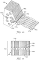
- FIG. 1 shows an exploded view of an exemplary embodiment of an extrusion die 30.
- Extrusion die 30 includes a plurality of shims 40.
- shims 40 typically several thousand shims; in some embodiments, at least 1000, 2000, 3000, 4000, 5000, 6000, 7000, 8000, 9000, or even at least 10,000
- fasteners e.g., through bolts 46 threaded onto nuts 48
- Inlet fittings 50a and 50b are provided on end blocks 44a and 44b respectively to introduce the materials to be extruded into extrusion die 30.
- inlet fittings 50a and 50b are connected to melt trains of conventional type.
- cartridge heaters 52 are inserted into receptacles 54 in extrusion die 30 to maintain the materials to be extruded at a desirable temperature while in the die.
- FIG. 2 shows a plan view of shim 40a from FIG. 1 .
- Shim 40a has first aperture 60a and second aperture 60b.
- first apertures 60a in shims 40 together define at least a portion of first cavity 62a.
- second apertures 60b in shims 40 together define at least a portion of second cavity 62b.
- Material to be extruded conveniently enters first cavity 62a via inlet port 50a, while material to be extruded conveniently enters second cavity 62b via inlet port 50b.
- Shim 40a has a duct 64 ending in a first dispensing orifice 66a in a dispensing surface 67.
- Shim 40a further has a passageway 68a affording a conduit between first cavity 62a and duct 64.
- the dimensions of the duct 64, and especially the first dispensing orifice 66a at its end is constrained by the dimensions desired in the polymer strands extruded from them. Since the strand speed of the strand emerging from the first dispensing orifice 66a is also of significance, manipulation of the pressure in cavity 62a and the dimensions of passageway 68a are used to set the desired strand speed.
- shim 40b is a reflection of shim 40a, having a passageway instead affording a conduit between second cavity 62b and second dispensing orifice 66b.
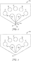
- FIG. 3 shows a plan view of shim 40c from FIG. 1 .
- Shim 40c has no passageway between either of first or second cavities 62a and 62b, respectively, and no duct opening onto dispensing surface 67.
- FIG. 4 shows a perspective partial cutaway detail view of plurality of shims 40 packed closely together and ready to be assembled into die 30 of FIG. 1 .
- plurality of shims 40 conveniently form a repeating sequence of four shims.
- First in the sequence from left to right as the view is oriented is shim 40a.
- passageway 68a which leads from cavity 62a to first dispensing orifice 66a in dispensing surface 67, can be seen.
- Second in the sequence is spacer shim 40c.
- shim 40b which is simply shim 40a turned upside down so there is a passageway (not seen in this FIG.) between cavity 62b and second dispensing orifices 66b in dispensing surface 67.
- second spacer shim 40c When complete die 30 is assembled with shims of this type in this way, and two flowable polymer containing compositions are introduced under pressure to cavities 62a and 62b, first and second polymeric strands respectively will emerge from first and second dispensing orifices 66a and 66b, supplied by cavities 62a and 62b. If the first polymeric strands have a first strand speed that is in a range from 2 to 6 (or even 2 to 4) times the second strand speed of the second polymeric strands, a net can be produced.
- the dispensing orifices 66a and 66b are alternating and collinear. This second feature is not a requirement of the disclosure, and this is illustrated in FIG. 5 .
- FIG. 5 a front close up view of a portion of a dispensing surface 567 of alternately assembled die 530 is illustrated.
- This assembly also includes a repeating sequence of shims, each repeat having six shims. First in the sequence, from right to left, are two shims 540a, one shim 540c, two shims 540b, and one shim 540c. Although not visualized in FIG.
- shims 540a have passageways analogous to passageways 68a, leading backwards and upwards as the drawing is oriented, together providing a fluid conduit with first cavity analogous to 62a.
- one spacer shim 540c which in this arrangement still helps define the first dispensing orifice 566a on its left and the second dispensing orifice 566b on its right.
- two shims 540b are two shims 540b.
- shims 540b have passageways analogous to passageways 68b, leading backwards and downwards as the drawing is oriented, together providing a fluid conduit with second cavity analogous to second cavity 62b.
- the first dispensing orifices 566a are collinear with each other, and the second dispensing orifices 566b are collinear with each other, they are offset from the first dispensing orifices 566a.
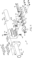
- FIG. 6 shows a perspective exploded view of an alternate embodiment of extrusion die 30'.
- Extrusion die 30' includes plurality of shims 40'.
- through bolts 46 and nuts 48 are used to assemble the shims 40' to the end blocks 44a' and 44b'.
- the end blocks 44a' and 44b' are fastened to manifold body 160, by bolts 202 pressing compression blocks 204 against the shims 40' and the end blocks 44a' and 44b'.
- Inlet fittings 50a' and 50b' are also attached to manifold body 160. These are in a conduit with two internal manifolds, of which only the exits 206a and 206b are visible in FIG. 6 . Molten polymeric material separately entering body 160 via inlet fittings 50a' and 50b' pass through the internal manifolds, out the exits 206a and 206b, through passages 208a and 208b in alignment plate 210 and into openings 168a and 168b (seen in FIG. 7 ).
- An expansion seal 164 is disposed between the shims 40' and the alignment plate 210. Expansion seal 164, along with the shims 40' together define the volume of the first and the second cavities (62a' and 62b' in FIG. 7 ). The expansion seal withstands the high temperatures involved in extruding molten polymer, and seals against the possibly slightly uneven rear surface of the assembled shims 40'. Expansion seal 164 may made from copper, which has a higher thermal expansion constant than the stainless steel conveniently used for both the shims 40' and the manifold body 160.
- Another useful expansion seal 164 material includes a polytetrafluoroethylene (PTFE) gasket with silica filler (available, for example, from Garlock Sealing Technologies, Palmyra, NY, under the trade designation “GYLON 3500” and “GYLON 3545”).
- PTFE polytetrafluoroethylene
- Cartridge heaters 52 may be inserted into body 160, conveniently into receptacles in the back of manifold body 160 analogous to receptacles 54 in FIG. 1 . It is an advantage of the embodiment of FIG. 6 that the cartridge heaters are inserted in the direction perpendicular to slot 66, in that it facilitates heating the die differentially across its width.
- Manifold body 160 is conveniently gripped for mounting by supports 212 and 214, and is conveniently attached to manifold body 160 by bolts 216.
- FIG. 7 shows a plan view of shim 40a' from FIG. 6 .
- Shim 40a' has first aperture 60a' and second aperture 60b'.
- first apertures 60a' in shims 40' together define at least a portion of first cavity 62a'.
- second apertures 60b' in shims 40' together define at least a portion of second cavity 62b'.
- Base end 166 of shim 40a' contacts expansion seal 164 when extrusion die 30' is assembled.
- Material to be extruded conveniently enters first cavity 62a' via apertures in expansion seal 164 and via shim opening 168a.
- material to be extruded conveniently enters first cavity 62a' via apertures in expansion seal 164 and via shim opening 168a.
- Shim 40a' has duct 64 ending in dispensing orifice 66a in dispensing surface 67. Shim 40a' further has passageway 68a' affording a conduit between first cavity 62a' and duct 64.
- shim 40c' is a reflection of shim 40a', having a passageway instead affording a conduit between second cavity 62b' and die duct 64. It might seem that strength members 170 would block the adjacent cavities and passageways, but this is an illusion - the flow has a route in the perpendicular-to-the-plane-of-the-drawing dimension when extrusion die 30' is completely assembled.
- shim 40b' is a reflection of 40a', having a passageway instead forming a conduit between second cavity 62b' and the dispensing orifice.
- FIG. 8 shows a plan view of shim 40c' from FIG. 6 is illustrated.
- Shim 40c' has no passageway between either of first or second cavities 62a' and 62b', respectively, and no duct opening onto dispensing surface 67.
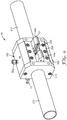
- FIG. 9 shows a perspective view of the extrusion die 30' of FIG. 6 , except for most of the shims 40' which have been omitted to allow the visualization of internal parts.
- FIG. 6 and FIG. 9 is more complicated than the embodiment of FIG. 1 , it has several advantages. First, it allows finer control over heating. Second, the use of manifold body 160 allows shims 40' to be center-fed, increasing side-to-side uniformity in the extruded ribbon region. Third, the forwardly protruding shims 40' allow dispensing surface 67 to fit into tighter locations on crowded production lines.
- the shims are typically 0.05 mm (2 mils) to 0.25 mm (10 mils) thick, although other thicknesses, including, for example, those from 0.025 mm (1 mil) to 1 mm (40 mils) may also be useful.
- Each individual shim is generally of uniform thickness, preferably with less than 0.005 mm (0.2 mil), more preferably, less than 0.0025 mm (0.1 mil) in variability.
- the shims are typically metal, preferably stainless steel. To reduce size changes with heat cycling, metal shims are preferably heat-treated.
- the shims can be made by conventional techniques, including wire electrical discharge and laser machining. Often, a plurality of shims are made at the same time by stacking a plurality of sheets and then creating the desired openings simultaneously. Variability of the flow channels is preferably within 0.025 mm (1 mil), more preferably, within 0.013 mm (0.5 mil).
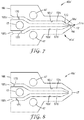
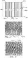
- FIG. 10 shows a schematic perspective view of a portion of extrusion die 1030, supplied with polymeric material and forming a net.
- Polymer from first cavity 1062a emerges as first strands 1070a from first dispensing orifices 1066a, and second strands 1070b are emerging from second dispensing orifices 1066b.
- Passageways 1068a (hidden behind the nearest shim in this view) and 1068b, and the pressures in cavities 1062a and 1062b are selected so that the strand speed of first strands 1070a are between about 2 and 6 times greater than the strand speed of second strands 1070b.
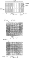
- FIG. 11 shows a front view of a portion of dispensing surface 1167 of alternately assembled die 1130.
- a repeated sequence of shims is present in which the dispensing orifices 1166a and 1166b are alternating and collinear.
- Each repeat in this sequence includes a repeating sequence of sixteen shims. First in the sequence are five shims 1140a, then three spacer shims 1140c, then five shims 1140b, then three spacer shims 1140c.
- FIG. 12 shows a front view of a portion of dispensing surface 1267 of alternately assembled die 1230.
- a repeated sequence of shims is present in which the dispensing orifices 1266a and 1266b are alternating and collinear.
- Each repeat in this sequence includes a repeating sequence of ten shims. First in the sequence are three shims 1240a, then two spacer shims 1240c, then three shims 1240b, then two spacer shims 1240c.
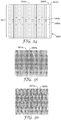
- FIG. 15 shows a front view of a portion of dispensing surface 1567 of assembled die 1530.
- a repeated sequence of shims is present in which dispensing orifices 1566a and 1566b are alternating and collinear. Each repeat in this sequence includes a repeating sequence of twelve shims. First in the sequence are four shims 1540a, then two spacer shims 1540c, then four shims 1540b, then two spacer shims 1540c.
- shims 1540b have an identification notch 1582
- shims 1540c have an identification notch 1582' to help verify that the die 1530 has been assembled in the desired manner.
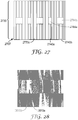
- FIG. 24 shows a front view of a portion of dispensing surface 2467 of alternately assembled die 2430.
- a repeated sequence of shims is present in which the dispensing orifices 2466a and 2466b are alternating and collinear.
- Each repeat in this sequence includes a repeating sequence of eight shims. First in the sequence are two shims 2440a, then two spacer shims 2440c, then two shims 2440b, then two spacer shims 2440c.
- FIG. 27 shows a front view of a portion of dispensing surface 2767 of alternately assembled die 2730.
- a repeated sequence of shims is present in which the dispensing orifices 2766a and 2766b are alternating and collinear.
- Each repeat in this sequence includes a repeating sequence of twenty-two shims. First in the sequence are four shims 2740a, then six spacer shims 2740c, then eight shims 2740b, then six spacer shims 2740c.
- FIG. 29 shows a front view of a portion of dispensing surface 2967 of alternately assembled die 2930.
- a repeated sequence of shims is present in which the dispensing orifices 2966a and 2966b are alternating and collinear.
- Each repeat in this sequence includes a repeating sequence of twelve shims. First in the sequence are two shims 2940a, then three spacer shims 2940c, then four shims 2940b, then three spacer shims 2940c.
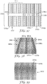
- FIG. 32 shows a front view of a portion of dispensing surface 3267 of alternately assembled die 3230 is illustrated.
- a repeated sequence of shims is present in which the dispensing orifices 3266a and 3266b are alternating and collinear.
- Each repeat in this sequence includes a repeating sequence of ten shims. First in the sequence are two shims 3240a, then two spacer shims 3240c, then four shims 3240b, then two spacer shims 3240c.
- FIG. 34 shows a front view of a portion of dispensing surface 3467 of alternately assembled die 3430 is illustrated.
- a repeated sequence of shims is present in which the dispensing orifices 3466a and 3466b are alternating and collinear.
- Each repeat in this sequence includes a repeating sequence of four shims. First in the sequence is one shim 3440a, then one spacer shim 3440c, then one shim 3440b, then one spacer shim 3440c.
- FIG. 37 shows a front view of a portion of dispensing surface 3767 of alternately assembled die 3730 is illustrated.
- a repeated sequence of shims is present in which the dispensing orifices 3766a and 3766b are alternating and collinear.
- Each repeat in this sequence includes a repeating sequence of ten shims.
- First in the sequence are two shims 3740a, then two spacer shims 3740c, then four shims 3740b, then two spacer shims 3740c.
- Assembled die 3730 also includes in addition to the repeated sequences a plurality of shims 3740a in zone 3741. This creates slot 3798.
- FIG. 44 shows a plan view of shim 4440, useful in connection with a die for forming netting with first and second strands made from the same material and extruded from a single cavity.
- Shim 4440 has aperture 4460.
- aperture 4460 When assembled with the shims of FIGS. 45-46 in the way described below in FIGS. 47-48 , aperture 4460 will define at least a portion of cavity 4462.
- passageway 4468 conducts polymer from cavity 4462 to first dispensing orifice 4466 on dispensing surface 4467.
- restriction 4470 adjacent first dispensing orifice 4466. Restriction 4470 increases the first strand speed of the first strand emerging from first dispensing orifice 4466 during use.
- FIG. 45 shows a plan view of shim 4540.
- Shim 4540 has an aperture 4560.
- aperture 4560 When assembled with the shims of FIGS. 44 and 46 in the way described below in FIGS. 47-48 , aperture 4560 will define at least a portion of cavity 4462.
- passageway 4568 conducts polymer from cavity 4462 to second dispensing orifice 4566 on dispensing surface 4567.
- restriction 4570 set back from second dispensing orifice 4566. Restriction 4570 decreases the second strand speed of the second strand emerging from second dispensing orifice 4566 during use.
- FIG. 46 shows a plan view of spacer shim 4640 useful in forming netting in conjunction with the shims 4440 and 4540 of FIGS. 44 and 45 .
- Shim 4640 has cut-out 4660.
- cut-out 4660 When assembled with the shims of FIGS. 44-45 in the way described below in FIGS. 47-48 , cut-out 4660 will define at least a portion of cavity 4462.
- Cut-out 4660 has open end 4661 on the end opposite dispensing surface 4667. Open end 4661 allows the inflow of polymer into cavity 4462 when assembled with the other shims and mounted in a die mount analogous to that shown in FIG. 6 .
- FIG. 47 shows a detail perspective view of a plurality of shims 4741 formed by, from left to right, one spacer shim 4640, one shim 4540, one spacer shim 4640, and one shim 4440.
- apertures 4460 and 4560, and cut-out 4660 (not labeled) together define a portion of cavity 4462.
- the mass flow of the first strand emerging from first dispensing orifice 4466 will be approximately equal to the mass flow of the second strand emerging from second dispensing orifice 4566.
- the first strand speed of the first strand will be significantly faster than the second strand speed of the second strand.
- FIG. 48 shows a detail perspective view of the plurality of shims of FIG. 47 , seen from the reverse angle, with the nearest instance of shim 4640 removed for visual clarity. In this view of the reduced plurality of shims 4741, restriction 4570 can be better appreciated.
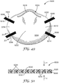
- FIG. 49 shows an example of a respirator 5000 of the present disclosure.
- the respirator 5000 includes a mask body 5002 and a harness 5004.
- the harness 5004 includes first and second straps 5006 and 5008.
- the straps 5006 and 5008 engage the mask body 5002 on first and second sides 5010 and 5012, respectively, of the mask body 5002.
- the straps 5006, 5008 may engage the mask body directly by being secured thereto through use of staples 5014 or other suitable mechanical fastener.
- the straps 5006, 5008 can be physically or chemically secured to the mask body 5002 through use of bonds, including welds or adhesive attachment. Ultrasonic welding may be used, for example, to secure the straps to a mask body.
- the netting 5016 in the straps 5006, 5008 melts to form solid non-porous plastic that mates with the polymeric material that includes the mask body.
- the polymeric material in the strands of the netting melts into or merges with the polymeric material in the fibers of the layer(s) that include the mask body.
- the mask body 5002 also may have a nose clip 5018 secured thereto, which allows the user to conform the mask body 5002 in the nose region 5020.
- an exhalation valve may be secured to the mask body to assist in the rapid displacement or purging of exhaled air from the interior gas space. The exhalation valve is commonly attached to the mask body at a central location 5022.
- the mask body 5002 may include a filtering structure 5024 that includes one or more layers of filter media, shaping layers, and/or cover webs.
- a respirator having this construction may be assembled as described in U.S. Patent No. 7,131,442 to Kronzer et al.
- FIG. 50 shows a cross section of the strap 5008.
- the strap 5008 can include first and second layers 5026 and 5028 of netting material juxtapositioned in an adjoining fashion.
- the two layers 5026, 5028 may be, for example, joined together by bonding, such as autogenous bonding or fusion, as the layers are coextruded at the same time, one on top of the other.
- the layers can be combined together in the die as a melt.
- the layers generally may have some natural affinity to each other, such that the intermixing and bonding between materials at the interface during the melt state holds the layers together.
- the two flow streams of the two layers may meet together inside the die and exit as a two-layered stranded product, or the layers may be each separately formed and placed in contact with each other while the polymer streams are still molten.
- the first and second layers 5026 , 5028 of the netting can be secured directly to each other.
- other layer(s) may be inserted between the two layers so that they are disposed therebetween in the final product.
- the first netting layer 5026 can be provided with a first color that is different from the color of the second netting layer 5028. The use of different colors can add an aesthetic effect to the strap and may also allow the user to more easily detect if the strap is in a twisted condition.
- the netting layers 5026, 5028 can be secured to one another such that the array of polymeric strands in each of the layers corresponds to one another when viewed from a plane projected onto a major surface 5030, 5030' of the strap, that is, in the direction of arrows x or y, respectively.
- the strap 5008 is constructed to be sufficiently porous such that the strap is air permeable from the first major surface 5030 to the second major surface 5030'.
- the strap 5008 has a series of open spaces 5031 between the strands 5033 through which air can pass.
- the strap may include first and second inner layers
- FIG. 51 shows the filtering structure 5024 in cross-section.
- the filtering structure 5024 may include one or more cover webs 5032 and 5034, a shaping layer 5035, and a filtration layer 5036.
- the cover webs 5032 and 5034 may be located on the outer sides of the filtering structure 5024 to capture any fibers that could come loose therefrom.
- the cover webs 5032 and 5034 are made from a selection of fibers that provide a comfortable feel, particularly on the side 5038 of the filtering structure 5024 that makes contact with the wearer's face.
- the filtering structure that is used in connection with respirators suitable for use in connection with the present disclosure may take on a variety of different shapes and configurations. As shown in FIG. 51 , the filtering structure may have a plurality of layers, including a fibrous filtration layer and one or more fibrous cover webs. When the respirator is a molded mask, the mask body may also include a shaping layer. See, e.g., U.S. Patent Nos. 6,923,182 to Angadjivand et al. ; 7,131,442 to Kronzer et al. ; 6,923,182 and 6,041,782 to Angadjivand et al. ; 4,807,619 to Dyrud et al.
- the filtering structure removes contaminants from the ambient air and may also act as a barrier layer that precludes liquid splashes from entering the mask interior.
- the outer cover web can act to stop or slow any liquid splashes, and the inner filtering structure may then contain them if there is penetration past the other layers.
- the filtering structure can be of a particle capture or gas and vapor type filter.
- the filtering structure may include multiple layers of similar or dissimilar filter media and one or more cover webs as the application requires. If the respirator contains a fluid impermeable mask body that has one or more filter cartridges attached to it ( see, e.g., U.S Patent Nos. 6,874,499 to Viner et al.
- the filtering structure may be disposed within the filtering cartridge. Filtering structures located in filter cartridges do not need shaping layers to support them.
- Filters that may be beneficially employed in a respirator of the disclosure are generally low in pressure drop (for example, less than about 195 to 295 Pascals at a face velocity of 13.8 centimeters per second) to minimize the breathing work of the mask wearer.
- Filtration layers additionally are flexible and have sufficient shear strength so that they generally retain their structure under the expected use conditions.
- particle capture filters include one or more webs of fine inorganic fibers (such as fiberglass) or polymeric synthetic fibers. Synthetic fiber webs may include electret-charged polymeric microfibers that are produced from processes such as meltblowing. Polyolefin microfibers formed from polypropylene that has been electrically charged provide particular utility for particulate capture applications.
- the filtration layer is typically chosen to achieve a desired filtering effect.
- the filtration layer generally will remove a high percentage of particles and/or or other contaminants from the gaseous stream that passes through it.
- the fibers selected depend upon the kind of substance to be filtered and, typically, are chosen so that they do not become bonded together during the manufacturing operation.
- the filtration layer may come in a variety of shapes and forms and typically has a thickness of about 0.2 millimeters (mm) to 1 centimeter (cm), more typically about 0.3 mm to 0.5 cm, and it could be a generally planar web or it could be corrugated to provide an expanded surface area. See, e.g., U.S. Patent Nos.
- the filtration layer also may include multiple filtration layers joined together by an adhesive or any other means.
- any suitable material that is known (or later developed) for forming a filtering layer may be used as the filtering material.
- Webs of melt-blown fibers, such as those taught in Wente, Van A., Superfine Thermoplastic Fibers, 48 Indus. Engn. Chem., 1342 et seq. (1956 ), especially when in a persistent electrically charged (electret) form are especially useful ( see, e.g., U.S. Patent No. 4,215,682 to Kubik et al. ).
- melt-blown fibers may be microfibers that have an effective fiber diameter less than about 20 micrometers ( ⁇ m) (referred to as BMF for "blown microfiber"), typically about 1 to 12 ⁇ m. Effective fiber diameter may be determined according to Davies, C. N., The Separation Of Airborne Dust Particles, Institution Of Mechanical Engineers, London, Proceedings 1B, 1952 . Particularly preferred are BMF webs that contain fibers formed from polypropylene, poly(4-methyl-1-pentene), and combinations thereof. Electrically charged fibrillated-film fibers as taught in van Turnhout, U.S. Patent Re.
- 31,285 also may be suitable, as well as rosin-wool fibrous webs and webs of glass fibers or solution-blown, or electrostatically sprayed fibers, especially in microfiber form.
- Electric charge can be imparted to the fibers by contacting the fibers with water as disclosed in U.S. Patent Nos. 6,824,718 to Eitzman et al. ; 6,783,574 to Angadjivand et al. ; 6,743,464 to Insley et al. ; 6,454,986 and 6,406,657 to Eitzman et al. ; and 6,375,886 and 5,496,507 to Angadjivand et al.
- Electric charge also may be imparted to the fibers by corona charging as disclosed in U.S. Patent No. 4,588,537 to Klasse et al. or by tribocharging as disclosed in U.S. Patent No. 4,798,850 to Brown .
- additives can be included in the fibers to enhance the filtration performance of webs produced through the hydro-charging process ( see U.S. Patent No. 5,908,598 to Rousseau et al. ).
- Fluorine atoms in particular, can be disposed at the surface of the fibers in the filter layer to improve filtration performance in an oily mist environment. See U.S. Patent Nos.
- Typical basis weights for electret BMF filtration layers are about 10 to 100 grams per square meter (g/m 2 ).
- the basis weight may be about 20 to 40 g/m 2 and about 10 to 30 g/m 2 , respectively.
- sorptive materials such as activated carbon may be disposed between the fibers and/or various layers that include the filtering structure.
- sorbent component may be used for removing hazardous or odorous gases from the breathing air.
- Sorbents may include powders or granules that are bound in a filter layer by adhesives, binders, or fibrous structures. See U.S. Patent Nos. 6,334,671 to Springett et al. and 3,971,373 to Braun .
- a sorbent layer can be formed by coating a substrate, such as fibrous or reticulated foam, to form a thin coherent layer.
- Sorbent materials may include activated carbons that are chemically treated or not, porous alumna-silica catalyst substrates, and alumna particles.
- activated carbons that are chemically treated or not
- porous alumna-silica catalyst substrates and alumna particles.
- An example of a sorptive filtration structure that may be conformed into various configurations is described in U.S. Patent No. 6,391,429 to Senkus et al.
- the cover webs also may have filtering abilities, although typically not nearly as good as the filtering layer and/or may serve to make a filtering face-piece respirator more comfortable to wear.
- the cover webs may be made from nonwoven fibrous materials such as spun bonded fibers that contain, for example, polyolefins, and polyesters. See, e.g., U.S. Patent Nos. 6,041,782 to Angadjivand et al. ; 4,807,619 to Dyrud et al. ; and 4,536,440 to Berg . When a wearer inhales, air is drawn through the mask body, and airborne particles become trapped in the interstices between the fibers, particularly the fibers in the filter layer.
- the inner cover web can be used to provide a smooth surface for contacting the wearer's face, and the outer cover web, in addition to providing splash fluid protection, can be used for entrapping loose fibers in the mask body and for aesthetic reasons.
- the cover web typically does not provide any substantial filtering benefits to the filtering structure, although it can act as a pre-filter when disposed on the exterior of (or upstream to) the filtration layer.
- an inner cover web preferably has a comparatively low basis weight and is formed from comparatively fine fibers.
- the cover web may be fashioned to have a basis weight of about 5 to 50g/m 2 (typically 10 to 30g/m 2 ), and the fibers may be less than 3.5 denier (typically less than 2 denier, and more typically less than 1 denier but greater than 0.1 denier). Fibers used in the cover web often have an average fiber diameter of about 5 to 24 micrometers, typically of about 7 to 18 micrometers, and more typically of about 8 to 12 micrometers.
- the cover web material may have a degree of elasticity (typically, but not necessarily, 100 to 200% at break) and may be plastically deformable.
- Suitable materials for the cover web may be blown microfiber (BMF) materials, particularly polyolefin BMF materials, for example polypropylene BMF materials (including polypropylene blends and also blends of polypropylene and polyethylene).
- BMF blown microfiber
- a suitable process for producing BMF materials for a cover web is described in U.S. Patent No. 4,013,816 to Sabee et al.
- the web may be formed by collecting the fibers on a smooth surface, typically a smooth-surfaced drum or a rotating collector. See U.S. Patent No. 6,492,286 to Berrigan et al. Spun-bond fibers also may be used.
- a typical cover web may be made from polypropylene or a polypropylene/polyolefin blend that contains 50 weight percent or more polypropylene. These materials have been found to offer high degrees of softness and comfort to the wearer and also, when the filter material is a polypropylene BMF material, to remain secured to the filter material without requiring an adhesive between the layers.
- Polyolefin materials that are suitable for use in a cover web may include, for example, a single polypropylene, blends of two polypropylenes, and blends of polypropylene and polyethylene, blends of polypropylene and poly(4-methyl-1-pentene), and/or blends of polypropylene and polybutylene.
- a fiber for the cover web is a polypropylene BMF made from the polypropylene resin "Escorene 3505G” from Exxon Corporation, providing a basis weight of about 25 g/m 2 and having a fiber denier in the range 0.2 to 3.1 (with an average, measured over 100 fibers of about 0.8).
- Another suitable fiber is a polypropylene/polyethylene BMF (produced from a mixture comprising 85 percent of the resin "Escorene 3505G” and 15 percent of the ethylene/alpha-olefin copolymer "Exact 4023" also from Exxon Corporation) providing a basis weight of about 25 g/m 2 and having an average fiber denier of about 0.8.
- Suitable spunbond materials are available, under the trade designations "Corosoft Plus 20", “Corosoft Classic 20” and “Corovin PP-S-14", from Corovin GmbH of Peine, Germany, and a carded polypropylene/viscose material available, under the trade designation "370/15", from J.W. Suominen OY of Nakila, Finland.
- Cover webs typically have very few fibers protruding from the web surface after processing and therefore have a smooth outer surface. Examples of cover webs that may be used in a respirator of the present disclosure are described, e.g., in U.S. Patent No. 6,041,782 to Angadjivand ; U.S. Patent 6,123,077 to Bostock et al. ; and WO 96/28216A to Bostock et al.
- the shaping layer(s) may be formed from at least one layer of fibrous material that can be molded to the desired shape with the use of heat and that retains its shape when cooled. Shape retention is typically achieved by causing the fibers to bond to each other at points of contact between them, for example, by fusion or welding. Any suitable material known for making a shape-retaining layer of a direct-molded respiratory mask may be used to form the mask shell, including, for example, a mixture of synthetic staple fiber, preferably crimped, and bicomponent staple fiber.
- Bicomponent fiber is a fiber that includes two or more distinct regions of fibrous material, typically distinct regions of polymeric materials. Typical bicomponent fibers include a binder component and a structural component.
- the binder component allows the fibers of the shape-retaining shell to be bonded together at fiber intersection points when heated and cooled. During heating, the binder component flows into contact with adjacent fibers.
- the shape-retaining layer can be prepared from fiber mixtures that include staple fiber and bicomponent fiber in a weight-percent ratios that may range, for example, from 0/100 to 75/25.
- the material includes at least 50 weight-percent bicomponent fiber to create a greater number of intersection bonding points, which, in turn, increase the resilience and shape retention of the shell.
- Suitable bicomponent fibers that may be used in the shaping layer include, for example, side-by-side configurations, concentric sheath-core configurations, and elliptical sheath-core configurations.
- One suitable bicomponent fiber is the polyester bicomponent fiber available, under the trade designation "KOSA T254" (12 denier, length 38 mm), from Kosa of Charlotte, N.C., U.S.A., which may be used in combination with a polyester staple fiber, for example, that available from Kosa under the trade designation "T259” (3 denier, length 38 mm) and possibly also a polyethylene terephthalate (PET) fiber, for example, that available from Kosa under the trade designation "T295" (15 denier, length 32 mm).
- PET polyethylene terephthalate
- the bicomponent fiber may include a generally concentric sheath-core configuration having a core of crystalline PET surrounded by a sheath of a polymer formed from isophthalate and terephthalate ester monomers.
- the latter polymer is heat softenable at a temperature lower than the core material.
- Polyester has advantages in that it can contribute to mask resiliency and can absorb less moisture than other fibers.
- the shaping layer can be prepared without bicomponent fibers.
- fibers of a heat-flowable polyester can be included together with staple, preferably crimped, fibers in a shaping layer so that, upon heating of the web material, the binder fibers can melt and flow to a fiber intersection point where it forms a mass, that upon cooling of the binder material, creates a bond at the intersection point.
- Staple fibers (for the shaping component) that are pre-treated with Ammonium Polyphosphate type intumescent FR agents may be used in connection with the present disclosure in addition to or in lieu of a spray-application of the agent. Having the staple fibers contain, or, otherwise being treated with, the agent and then formed into a shell (using binder fibers to hold it together) would be another pathway to employ the agents for our purpose.
- the web When a fibrous web is used as the material for the shape-retaining shell, the web can be conveniently prepared on a "Rando Webber" air-laying machine (available from Rando Machine Corporation, Cincinnati, N.Y.) or a carding machine.
- the web can be formed from bicomponent fibers or other fibers in conventional staple lengths suitable for such equipment.
- the layer preferably has a basis weight of at least about 100 g/m 2 , although lower basis weights are possible. Higher basis weights, for example, approximately 150 or more than 200 g/m 2 , may provide greater resistance to deformation and greater resiliency and may be more suitable if the mask body is used to support an exhalation valve.
- the shaping layer typically has a maximum density of about 0.2 g/cm 2 over the central area of the mask.
- the shaping layer would have a thickness of about 0.3 to 2.0, more typically about 0.4 to 0.8 millimeters.
- Examples of shaping layers suitable for use in the present disclosure are described in the following patents: U.S. Patent Nos. 5,307,796 to Kronzer et al. ; 4,807,619 to Dyrud et al. ; and 4,536,440 to Berg .
- Staple fibers (for the shaping component) that are pre-treated with Ammonium Polyphosphate type intumescent FR agents may be used in connection with the present disclosure in addition to or in lieu of a spray-application of the agent. Having the staple fibers contain, or, otherwise being treated with, the agent and then formed into a shell (using binder fibers to hold it together) would be another pathway to employ the agents for our purpose.
- the strap(s) that are used in the respirator harness preferably can be expanded to greater than twice its total length and can be returned to its relaxed state many times throughout the useful life of the respirator.
- the strap also could possibly be increased to three or four times its relaxed state length and can be returned to its original condition without any damage thereto when the tensile forces are removed.
- the elastic limit thus is preferably not less than two, three, or four times the relaxed-state length of the strap(s).
- the strap(s) are about 20 to 30 cm long, 3 to 20 mm wide, and about 0.3 to 1 mm thick.
- the strap(s) may extend from the first side of the respirator to the second side as a continuous strap or the strap may have a plurality of parts, which can be joined together by further fasteners or buckles.
- the strap may have first and second parts that are joined together by a fastener that can be quickly uncoupled by the wearer when removing the mask body from the face.
- the strap may form a loop that is placed around the wearer's ears. See, e.g., U.S. Patent No. 6,394,090 to Chen et al. Examples of fastening or clasping mechanism that may be used to joint one or more parts of the strap together is shown, for example, in the following U.S. Patent Nos.
- the harness also may include a reusable carriage, one or more buckles, and/or a crown member to support the respirator on a person's head. See, e.g., U.S. Patent Nos. 6,732,733 and 6,457,473 to Brostrom et al. ; and 6,591,837 and 6,715,490 to Byram .
- a filtering face-piece respirator has been illustrated in showing the present disclosure, the respirator may include a compliable rubber-type mask that has one or more filter cartridges attached to it. See, e.g., U.S. Patent Nos.
- an exhalation valve may be attached to the mask body to facilitate purging exhaled air from the interior gas space.
- the use of an exhalation valve may improve wearer comfort by rapidly removing the warm moist exhaled air from the mask interior. See, e.g., U.S. Patent Nos. 7,188,622 , 7,028,689 , and 7,013,895 to Martin et al. ; 7,428,903 , 7,311,104 , 7,117,868 , 6,854,463 , 6,843,248 , and 5,325,892 to Japuntich et al. ; 7,302,951 and 6,883,518 to Mittelstadt et al. ; and RE37,974 to Bowers.
- any exhalation valve that provides a suitable pressure drop and that can be properly secured to the mask body may be used in connection with the present disclosure to rapidly deliver exhaled air from the interior gas space to the exterior gas space.
- a nose clip that is used with filtering face-piece respirators of the present disclosure may be essentially any additional part that assists in improving the fit over the wearer's nose. Because the wearer's face exhibits a major change in contour in the nose region, a nose clip may be used to better assist in achieving the appropriate fit in this location.
- the nose clip may include, for example, a pliable dead soft band of metal such as aluminum, which can be shaped to hold the mask in a desired fitting relationship over the nose of the wearer and where the nose meets the cheek.
- the nose clip may be linear in shape when viewed from a plane projected onto the mask body when in its folded or partially folded condition.
- the nose clip can be a M-shaped nose clip, an example of which is shown in U.S. Patent Nos.
- the dispenser can assist in placing a pliable nose clip in a curved shape ready for placement on the wearer's nose.
- the nose clip is in a substantially linear configuration while in the container.
- the constriction window is adapted to enable the outermost respirator to have the nose clip change from the substantially linear configuration to a curved configuration when pulled through the constriction window.
- the imparted curved configuration of the nose clip is concave relative to the mask body interior.
- the curvature imparted by the dispenser onto the nose clip generally matches the curvature of a person's nose.
- All polymer strands in the openwork structure may include a single polymeric material and/or a plurality of polymeric materials, including blends of polymers. Thus, adjoining strands may include the same or different polymeric materials.
- Polymers used to make netting and arrays of polymeric strands described herein are selected to be compatible with each other such that the first and second strands bond together as the bond regions. In methods described herein for making the nettings and arrays of polymeric strands, the bonding occurs in a relatively short period of time (typically less than 1 second). The bond regions, as well as the strands typically cool through air and natural convection and/or radiation.
- the strands in some embodiments, it may be desirable to select polymers of bonding strands that have dipole interactions (or H-bonds) or covalent bonds. Bonding between strands has been observed to be improved by increasing the time that the strands are molten to enable more interaction between polymers. Bonding of polymers has generally been observed to be improved by reducing the molecular weight of at least one polymer and or introducing an additional comonomer to improve polymer interaction and/or reduce the rate or amount of crystallization. In some embodiments, the bond strength is greater than the strength of the strands forming the bond. In some embodiments, it may be desirable for the bonds to break and thus the bonds will be weaker than the strands.
- Suitable polymeric materials for extrusion from dies described herein, methods described herein, and for composite layers described herein include thermoplastic resins comprising polyolefins (e.g., polypropylene and polyethylene), polyvinyl chloride, polystyrene, nylons, polyesters (e.g., polyethylene terephthalate) and copolymers and blends thereof.
- polyolefins e.g., polypropylene and polyethylene
- polyvinyl chloride e.g., polystyrene
- nylons e.g., polystyrene
- polyesters e.g., polyethylene terephthalate
- Suitable polymeric materials for extrusion from dies described herein, methods described herein, and for composite layers described herein also include elastomeric materials (e.g., ABA block copolymers, polyurethanes, polyolefin elastomers, polyurethane elastomers, metallocene polyolefin elastomers, polyamide elastomers, ethylene vinyl acetate elastomers, and polyester elastomers).
- elastomeric materials e.g., ABA block copolymers, polyurethanes, polyolefin elastomers, polyurethane elastomers, metallocene polyolefin elastomers, polyamide elastomers, ethylene vinyl acetate elastomers, and polyester elastomers.
- Exemplary adhesives for extrusion from dies described herein, methods described herein, and for composite layers described herein include acrylate copolymer pressure sensitive adhesives, rubber based adhesives (e.g., those based on natural rubber, polyisobutylene, polybutadiene, butyl rubbers, styrene block copolymer rubbers such as styrene-butadiene-styrene block copolymers (SBS) and styrene-ethylene-butadiene-styrene (SEBS), etc.), adhesives based on silicone polyureas or silicone polyoxamides, polyurethane type adhesives, and poly(vinyl ethyl ether), and copolymers or blends of these.
- rubber based adhesives e.g., those based on natural rubber, polyisobutylene, polybutadiene, butyl rubbers, styrene block copolymer rubbers such as sty
- Other desirable materials include, for example, styrene-acrylonitrile, cellulose acetate butyrate, cellulose acetate propionate, cellulose triacetate, polyether sulfone, polymethyl methacrylate, polyurethane, polyester, polycarbonate, polyvinyl chloride, polystyrene, polyethylene naphthalate, copolymers or blends based on naphthalene dicarboxylic acids, polyolefins, polyimides, mixtures and/or combinations thereof.
- Exemplary release materials for extrusion from dies described herein, methods described herein, and for composite layers described herein include silicone-grafted polyolefins such as those described in U.S. Patent Nos.
- silicone block copolymers such as those described in PCT Publication No. WO96039349, published December 12, 1996 , low density polyolefin materials such as those described in U.S. Patent Nos. 6,228,449 , 6,348,249 , and 5,948,517 to Meyer .
- first and second polymeric materials to make nettings and arrays of polymeric strands described herein each have a different modulus (i.e., one relatively higher to the other).
- first and second polymeric materials to make nettings and arrays of polymeric strands described herein, each have a different yield strength.
- polymeric materials used to make nettings and arrays described herein may include a colorant (e.g., pigment and/or dye) for functional (e.g., optical effects) and/or aesthetic purposes (e.g., each has different color/shade).
- a colorant e.g., pigment and/or dye
- Suitable colorants are those known in the art for use in various polymeric materials. Exemplary colors imparted by the colorant include white, black, red, pink, orange, yellow, green, aqua, purple, and blue.
- the amount of colorant(s) to be used in specific embodiments can be readily determined by those skilled in the (e.g., to achieve desired color, tone, opacity, transmissivity, etc.). If desired, the polymeric materials may be formulated to have the same or different colors.
- nettings and arrays of polymeric strands described herein have a basis weight in a range from 5 g/m 2 to 400 g/m 2 (in some embodiments, 10 g/m 2 to 300 g/m 2 ), for example, nettings as-made from dies described herein.
- nettings and arrays of polymeric strands described herein have a strand pitch in a range from 0.5 mm to 20 mm (in some embodiments, in a range from 0.5 mm to 10 mm).
- nettings and arrays of polymeric strands described herein are attached to a backing.
- the backings may be, for example, one of a film, net, or non-woven in elastic form or periodically cut to allow for expansion when a tensile force is applied.
- the nonwoven may be, for example, a spun bond web constructed like one of the cover webs described below.
- nettings and arrays of polymeric strands described herein have a machine direction and a cross-machine direction, where the netting or arrays of polymeric strands is elastic in machine direction, and inelastic in the cross-machine direction.
- Elastic means that the material will substantially resume its original shape after being stretched (i.e., will sustain only a small permanent set following deformation and relaxation which set is less than 20 percent (in some embodiments, less than 10 percent) of the original length at moderate elongation (i.e., about 400-500%; in some embodiments, up to 300% to 1200%, or even up to 600 to 800%) elongation at room temperature).
- the elastic material can be both pure elastomers and blends with an elastomeric phase or content that will still exhibit substantial elastomeric properties at room temperature.
- arrays described herein of alternating first and second polymeric strands exhibit at least one of diamond-shaped or hexagonal-shaped openings. Long bond lengths, relative to the pitch of the bond in the machine direction, tend to create diamond shaped nets, whereas short bond lengths tend to create hexagon shaped nets.
- the bond regions have an average largest dimension perpendicular to the strand thickness, where the polymeric strands have an average width, and where the average largest dimension of the bond regions is at least 2 (in some embodiments, at least 2.5, 3, 3.5, or even at least 4) times greater than the average width of the polymeric strands.
- a strap described herein includes bond lines as shown, for example, in FIGS. 41 and 42 , where netting 4100 and 4200, respectively, have bond lines 4101, 4201.
- the present disclosure also provides a strap that includes two nettings described herein with a ribbon region disposed there between. Typically, the netting and ribbon region are integral.
- the present disclosure also provides an article comprising netting described herein disposed between two ribbon regions. Typically, the netting and ribbon regions are integral.
- the ribbon region has a major surface with engagement posts thereon. An example, without engagements posts, is shown in FIG. 38 , where netting 3800 includes netting 3871a and 3871b, each having first strands 3870a and second strands 3870b. Film regions 3899a, 3899b, and 3899c are attached to netting 3871a and 3871b.
- the present disclosure also provides a strap that includes more than one layer of openwork structures.
- the layers may include strands made from different polymers and that have different elasticities.
- the inner layers may be highly elastic and tacky, while the outer layers may be less tacky to provide better comfort to the user. Layers that are not tacky are not sticky to touch.
- the elastic nettings described herein can flex in the machine direction, cross direction, or both directions.
- Elastic netting can also provide a breathable, soft, and flexible strap.
- the elastic strap can be made as elastic in a first lengthwise direction and inelastic in a second direction normal thereto through use of an elastic and an inelastic strand.
- a 25.4 mm wide by 12.7 mm length hook sample (obtained under the trade designation "KN2854” from 3M Company, St. Paul, MN) was affixed to a 25.4 mm strip of printer paper with adhesive tape (obtained under the trade designation "TRM-300 Double Coated Tape” from 3M Company).
- the 12.7 mm edge of the hook was in the machine direction.
- the loop was cut into 25.4 mm wide strips along the machine direction of the sample.
- the hook and loop were mated aligning the machine directions and rolled down with a 2.05 kg rubber coated roller, one cycle forward and back.
- the construction was loaded in shear with a 500 gram dead weight for 10 seconds.
- the peel was measured in a tensile tester, (obtained under the trade designation "INSTRON 5500R Series" from Instron Engineering Corp., Canton, MA). The instrument was calibrated to an accuracy of 1 percent of the full scale, and the scale range used for the test was within 10-90 percent of full range. The initial jaw separation was 76.2 mm. The sample was peeled to failure at a constant rate of 300 mm/min. A minimum of 5 tests were performed and averaged for each hook and loop combination.
- the Dynamic Shear Test was used to measure the amount of force required to shear the sample of mechanical fastener hook material from a sample of loop fastener material.
- a 2.5 cm by 7.5 cm loop sample was cut with the short dimension being the machine direction of the hook.
- This loop sample was then reinforced with filament tape (obtained under the trade designation "#898 filament tape” from 3M Company).
- a 1.25 cm by 2.5 cm hook sample (“KN2854”) was also prepared. The long dimension is the machine direction of the hook.
- This sample was laminated to the end of a tab of filament tape 2.5 cm wide by 7.5 cm long. The filament tape was doubled over on itself on the end without hook to cover the adhesive.
- the hook was then placed centrally on the loop with long tab directions parallel to each other such that the loop tab extended past on the first end and the hook tab extended past on the second end.
- the hook was rolled down by hand with a 5 kg steel roll, 5 replicates up and back.
- the assembled tabs were placed into the jaws of a tensile tester (obtained under the trade designation "INSTRON 5500R Series" from Instron Engineering Corp.).
- the hook tab was placed in the top jaw, and the loop tab was placed in the bottom jaw.
- the sample was sheared to failure in a 180 degree angle at a crosshead speed of 30.5 cm per minute.
- the maximum load was recorded in grams.
- the force required to shear the mechanical fastener strip from the loop material was reported in grams/2.54 cm-width. A minimum of 5 tests were run and averaged for each hook and loop combination.
- a co-extrusion die as generally depicted in FIG. 1 was prepared.
- the thickness of each shim was 2 mil (0.051 mm).
- Five identical shims were stacked together to create an orifice width of 10 mils (0.254 mm) to the first cavity.
- Five identical shims were stacked together to create an orifice width of 10 mils (0.254 mm) to the second cavity.
- Three identical shims were stacked together to create an effective shim width of 6 mils (0.152 mm) for the spacer between orifices.
- the shims were formed from stainless steel, with perforations cut by wire electron discharge machining.
- the height of the first extrusion orifice was cut to 10 mils (0.254 mm).
- the height of the second set of extrusion orifices was cut to 10 mils (0.254 mm).
- the extrusion orifices were aligned in a collinear, alternating arrangement with a dispensing surface generally as shown in FIG 11 .
- the total width of the shim setup was 5 cm.
- the inlet fittings on the two end blocks were each connected to a conventional single-screw extruder.
- a chill roll was positioned adjacent to the distal opening of the co-extrusion die to receive the extruded material.
- the extruder feeding the first cavity was loaded with thirty-five melt flow index polypropylene pellets (obtained under the trade designation "EXXONMOBIL 3155 PP" from ExxonMobil, Irving, TX).
- the resulting netting had strand cross-sections of equal width and thickness with a cross sectional area ratio of 3.6:1.
- a digital optical image at 10x of the netting is shown in FIG. 13 , with first strands 1370a and second strands 1370b.
- Example 2 was made with the same die setup and materials as Example 1 except with the following conditions listed below: Orifice width 0.254 mm Orifice height 0.254 mm Ratio of orifice height to width 1:1 Ratio of first and second orifice area 1:1 Land spacing between orifices 0.152 mm Flow rate of first polymer 1.7 kg/hr Flow rate of second polymer 0.65 kg/hr Flow rate ratio first to second polymer 2.5:1 Extrusion temperature 205°C Quench roll temperature 50°C Quench takeaway speed 9 m/min.
- the resulting netting had first to second strand cross-sections with a cross sectional area ratio of 2.5:1.
- a digital optical image at 10x of the netting is shown in FIG. 14 , with first strands 1470a and second strands 1470b.
- a co-extrusion die as generally depicted in FIG. 1 was prepared.
- the thickness of each shim was 4 mils (0.102 mm).
- Four identical shims were stacked together to create an orifice width of 16 mils (0.406 mm) to the first cavity.
- Four identical shims were stacked together to create an orifice width of 16 mils (0.406 mm) to the second cavity.
- Two spacer shims provided the spacer between orifices.
- the shims were formed from stainless steel, with perforations cut by wire electron discharge machining.
- the height of the first extrusion orifice was cut to 30 mils (0.762 mm).
- the height of the second set of extrusion orifices was cut to 10 mils (0.254 mm).
- the extrusion orifices were aligned in a collinear arrangement as shown in FIG. 15 .
- the total width of the shim setup was 7.5 cm.
- the inlet fittings on the two end blocks were each connected to a conventional single-screw extruder.
- a chill roll was positioned adjacent to the distal opening of the co-extrusion die to receive the extruded material.
- the extruder feeding the first cavity was loaded with thirty-five melt flow index polypropylene pellets ("EXXONMOBIL 3155 PP").
- the resulting netting had first to second strand cross-sections with a cross sectional area ratio of 1:1.
- a digital optical image at 10x of the netting is shown in FIG. 16 , with first strands 1670a and second strands 1670b.
- a co-extrusion die as generally depicted in FIG. 1 was prepared.
- the thickness of each shim was 2 mil (0.051 mm).
- Three identical shims were stacked together to create an orifice width of 6 mils (0.152 mm) to the first cavity.
- Three identical shims were stacked together to create an orifice width of 6 mils (0.152 mm) to the second cavity.
- Two identical shims were stacked together to create an effective shim width of 4 mils (0.102 mm) for the spacer between orifices.
- the shims were formed from stainless steel, with perforations cut by wire electron discharge machining.
- the height of the first extrusion orifice was cut to 10 mils (0.254 mm).
- the height of the second set of extrusion orifices was cut to 10 mils (0.254 mm).
- the extrusion orifices were aligned in a collinear, alternating arrangement as shown in FIG. 12 .
- the total width of the shim setup was 5 cm.
- the inlet fittings on the two end blocks were each connected to a conventional single-screw extruder.
- a chill roll was positioned adjacent to the distal opening of the co-extrusion die to receive the extruded material.
- the extruder feeding the first cavity was loaded with thirty-five melt flow index polypropylene pellets ("EXXONMOBIL 3155 PP").
- the resulting netting had first to second strand cross-sections with a cross sectional area ratio of 2.8:1.
- a digital optical image at 10x of the netting is shown in FIG. 17 , with first strands 1770a and second strands 1770b.
- the die swell of the polymer strands was also measured as the polymer exited the die: First polymer die swell width 0.25mm Second polymer die swell width 0.125.
- a co-extrusion die as generally depicted in FIG. 1 was prepared.
- the thickness of each shim was 2 mil (0.051 mm).
- Two identical shims were stacked together to create an orifice width of 4 mils (0.102 mm) to the first cavity.
- Two identical shims were stacked together to create an orifice width of 4 mils (0.102 mm) to the second cavity.
- One shim formed the spacer between orifices.
- the shims were formed from stainless steel, with perforations cut by wire electron discharge machining.
- the height of the first extrusion orifice was cut to 10 mils (0.254 mm).
- the height of the second set of extrusion orifices was cut to 10 mils (0.254 mm).
- the extrusion orifices with connection to the first cavity were aligned in a collinear arrangement.
- the extrusion orifices with connection to the second cavity were aligned in a collinear arrangement.
- the alignment of the first and second set of orifices was offset by 100%, as shown in FIG. 5 .
- the total width of the shim setup was 5 cm.
- the inlet fittings on the two end blocks were each connected to a conventional single-screw extruder.
- a chill roll was positioned adjacent to the distal opening of the co-extrusion die to receive the extruded material.
- the extruder feeding the first cavity was loaded with thirty-five melt flow index polypropylene pellets ("EXXONMOBIL 3155 PP").
- the resulting netting had first to second strand cross-sections with a cross sectional area ratio of 4.5:1.
- a digital optical image at 10x of the netting is shown in FIG. 18 , with first strands 1870a and second strands 1870b.
- Example 6 was made with the same die setup and materials as Example 5 except with the following conditions listed below: Orifice width 0.102 mm Orifice height 0.254 mm Ratio of orifice height to width 2.5:1 Ratio of first and second orifice area 1:1 Land spacing between orifices 0.05 mm Flow rate of first polymer 1.12 kg/hr Flow rate of second polymer 0.25 kg/hr Flow rate ratio first to second polymer 4.5:1 Extrusion temperature 205°C Quench roll temperature 50°C Quench takeaway speed 9 m/min.
- the resulting netting had first to second strand cross-sections with a cross sectional area ratio of 4.5:1.
- a digital optical image at 10x of the netting is shown in FIG. 19 , with First strands 1970a and second strands 1970b.
- Example 7 was made with the same die setup and materials as Example 5 except with the following conditions listed below: Orifice width 0.102 mm Orifice height 0.254 mm Ratio of orifice height to width 2.5:1 Ratio of first and second orifice area 1:1 Land spacing between orifices 0.05 mm Flow rate of first polymer 2.1 kg/hr Flow rate of second polymer 0.5 kg/hr Flow rate ratio first to second polymer 4.1:1 Extrusion temperature 205°C Quench roll temperature 50°C Quench takeaway speed 4.5 m/min.
- the resulting netting had first to second strand cross-sections with a cross sectional area ratio of 4.1:1.
- a digital optical image at 10x of the netting is shown in FIG. 20 , with first strands 2070a and second strands 2070b.
- Example 8 was made with the same die setup and materials as Example 5 except with the following conditions listed below: Orifice width 0.102 mm Orifice height 0.254 mm Ratio of orifice height to width 2.5:1 Ratio of first and second orifice area 1:1 Land spacing between orifices 0.05 mm Flow rate of first polymer 2.1 kg/hr Flow rate of second polymer 0.5 kg/hr Flow rate ratio first to second polymer 4.1:1 Extrusion temperature 205°C Quench roll temperature 50°C Quench takeaway speed 9.0 m/min.
- the resulting netting had first to second strand cross-sections with a cross sectional area ratio of 4.1:1.
- a digital optical image at 10x of the netting is shown in FIG. 21 with first strands 2170a and second strands 2170b.
- Examples 4-7 demonstrate that the strand net bonding rate increases as the strand polymer throughput rate is increased.
- the net bonding pitch increases as the drawing rate from the die increases for a given polymer throughput rate.
- Example 9 was made with the same die setup and materials as Example 5 except with the following conditions listed below: Orifice width 0.102 mm Orifice height 0.254 mm Ratio of orifice height to width 2.5:1 Ratio of first and second orifice area 1:1 Land spacing between orifices 0.05 mm Flow rate of first polymer 2.0 kg/hr Flow rate of second polymer 1.0 kg/hr Flow rate ratio first to second polymer 2.0:1 Extrusion temperature 205°C Quench roll temperature 50°C Quench takeaway speed 9 m/min.
- the resulting netting had first to second strand cross-sections with a cross sectional area ratio of 2.0:1.
- a digital optical image at 10x of the netting is shown in FIG. 22 , with first strands 2270a and second strands 2270b.
- Example 10 was made with the same die setup as Example 5.
- the inlet fittings on the two end blocks were each connected to a conventional single-screw extruder.
- a chill roll was positioned adjacent to the distal opening of the co-extrusion die to receive the extruded material.
- the extruder feeding the first cavity was loaded with twenty-two melt flow index copolymer polypropylene pellets ("VISTAMAX 1120").
- the resulting netting had first to second strand cross-sections with a cross sectional area ratio of 1.7:1.
- a digital optical image at 10x of the netting is shown in FIG. 23 , with first strands 2370a and second strands 2370b.
- a co-extrusion die as generally depicted in FIG. 1 was prepared.
- the thickness of each shim was 2 mil (0.051 mm).
- Two identical shims were stacked together to create an orifice width of 4 mils (0.102 mm) to the first cavity.
- Two identical shims were stacked together to create an orifice width of 4 mils (0.102 mm) to the second cavity.
- Two identical shims were stacked together to create an effective shim width of 4 mils (0.102 mm) for the spacer between orifices.
- the shims were formed from stainless steel, with perforations cut by wire electron discharge machining.
- the height of the first extrusion orifice was cut to 10 mils (0.254 mm).
- the height of the second set of extrusion orifices was cut to 10 mils (0.254 mm).
- the extrusion orifices were aligned in a collinear, alternating arrangement as shown in FIG. 24 .
- the total width of the shim setup was 5 cm.
- the inlet fittings on the two end blocks were each connected to a conventional single-screw extruder.
- a chill roll was positioned adjacent to the distal opening of the co-extrusion die to receive the extruded material.
- the extruder feeding the first cavity was loaded with thirty-five melt flow index polypropylene pellets ("EXXONMOBIL 3155 PP").
- the resulting netting had first to second strand cross-sections with a cross sectional area ratio of 5.7:1.
- a digital optical image at 10x of the netting is shown in FIG. 25 , with first strands 2570a and second strands 2570b.
- Example 12 was made with the same die setup as Example 11.
- the inlet fittings on the two end blocks were each connected to a conventional single-screw extruder.
- a chill roll was positioned adjacent to the distal opening of the co-extrusion die to receive the extruded material.
- the extruder feeding the first cavity was loaded with one hundred melt flow index polypropylene pellets (obtained under the trade designation "TOTAL 3860” from Total Petrochemicals, Houston, TX).
- the resulting netting had first to second strand cross-sections with a cross sectional area ratio of 3:1.
- a digital optical image at 10x of the netting is shown in FIG. 26 , with first strands 2670a and second strands 2670b.
- a co-extrusion die as generally depicted in FIG. 1 was prepared.
- the thickness of each shim was 4 mils (0.102 mm).
- Eight identical shims were stacked together to create an orifice width of 32 mils (0.813 mm) to the first cavity.
- Four identical shims were stacked together to create an orifice width of 16 mils (0.406 mm) to the second cavity.
- Six identical shims were stacked together to create an effective shim width of 24 mils (0.610 mm) for the spacer between orifices.
- the shims were formed from stainless steel, with perforations cut by wire electron discharge machining.
- the height of the first extrusion orifice was cut to 30 mils (0.762 mm).
- the height of the second set of extrusion orifices was cut to 30 mils (0.762 mm).
- the extrusion orifices were aligned in a collinear, alternating arrangement as shown in FIG. 27 .
- the total width of the shim setup was 5 cm.
- the inlet fittings on the two end blocks were each connected to a conventional single-screw extruder.
- a chill roll was positioned adjacent to the distal opening of the co-extrusion die to receive the extruded material.
- the extruder feeding the first cavity was loaded with thirty-five melt flow index polypropylene pellets ("EXXONMOBIL 3155 PP").
- the resulting netting had first to second strand cross-sections with a cross sectional area ratio of 0.9:1.
- a digital optical image at 10x of the netting is shown in FIG. 28 , with first strands 2870a and second strands 2870b.
- a co-extrusion die as generally depicted in FIG. 1 was prepared.
- the thickness of each shim was 4 mils (0.102 mm).
- Four identical shims were stacked together to create an orifice width of 16 mils (0.406 mm) to the first cavity.
- Two identical shims were stacked together to create an orifice width of 8 mils (0.203 mm) to the second cavity.
- Three identical shims were stacked together to create an effective shim width of 12 mils (0.305 mm) for the spacer between orifices.
- the shims were formed from stainless steel, with perforations cut by wire electron discharge machining.
- the height of the first extrusion orifice was cut to 30 mils (0.762 mm).
- the height of the second set of extrusion orifices was cut to 30 mils (0.762 mm).
- the extrusion orifices were aligned in a collinear, alternating arrangement as shown in FIG. 29 .
- the total width of the shim setup was 15 cm.
- thermoplastic polyurethane pellets obtained under the trade designation "IROGRAN 440" from Huntsman, Auburn Hills, MI).
- thermoplastic polyurethane pellets (“IROGRAN 440").
- Other process conditions are listed below: Orifice width for the first cavity 0.406 mm Orifice height for the first cavity 0.762 mm Orifice width of the second cavity 0.203 mm Orifice height of the second cavity 0.762 mm Ratio of orifice height to width for oscillating strand 3.75:1 Ratio of first and second orifice area 2:1 Land spacing between orifices 0.305 mm Flow rate of first polymer 2.1 kg/hr Flow rate of second polymer 3.2 kg/hr Flow rate ratio first to second polymer 0.64:1 Extrusion temperature 218°C Quench roll temperature 13°C Quench takeaway speed 4.4 m/min.
- the resulting netting had first to second strand cross-sections with a cross sectional area ratio of 0.64:1.
- a digital optical image at 10x of the netting is shown in FIG. 30 , with first strands 3070a and second strands 3070b.
- Example 15 was made with the same die as Example 14.
- the inlet fittings on the two end blocks were each connected to a conventional single-screw extruder.
- a chill roll was positioned adjacent to the distal opening of the co-extrusion die to receive the extruded material.
- the extruder feeding the first cavity was loaded with styrene ethylene/butylene block copolymer pellets (obtained under the trade designation "KRATON 1657” from Kraton Polymers, Houston, TX).
- the resulting netting had first to second strand cross-sections with a cross sectional area ratio of 1:1.
- a digital optical image at 10x of the netting is shown in FIG. 31 , with first strands 3170a and second strands 3170b.
- a co-extrusion die as generally depicted in FIG. 1 was prepared.
- the thickness of each shim was 4 mils (0.102 mm).
- Four identical shims were stacked together to create an orifice width of 16 mils (0.406 mm) to the first cavity.
- Two identical shims were stacked together to create an orifice width of 8 mils (0.203 mm) to the second cavity.
- Two identical shims were stacked together to create an effective shim width of 8 mils (0.203 mm) for the spacer between orifices.
- the shims were formed from stainless steel, with perforations cut by wire electron discharge machining.
- the height of the first extrusion orifice was cut to 30 mils (0.762 mm).
- the height of the second set of extrusion orifices was cut to 30 mils (0.762 mm).
- the extrusion orifices were aligned in a collinear, alternating arrangement as shown in FIG. 32 .
- the total width of the shim setup was 15 cm.
- the inlet fittings on the two end blocks were each connected to a conventional single-screw extruder.
- a chill roll was positioned adjacent to the distal opening of the co-extrusion die to receive the extruded material.
- the extruder feeding the first cavity was loaded with styrene isoprene styrene block copolymer pellets (obtained under the trade designation "VECTOR 4114" from Dexco Polymers LP, Houston, TX), dry blended at 50% with C-5 hydrocarbon tackifier flakes (“WINGTAC PLUS”), and then dry blended with 1% antioxidant powder (obtained under the trade designation "IRGANOX 1010" from BASF, Luwigshafen, Germany).
- the extruder feeding the second cavity was loaded with styrene-isoprene-styrene block copolymer pellets ("VECTOR 4114”), dry blended at 50% with C-5 hydrocarbon tackifier flakes (“WINGTAC PLUS”), and then dry blended with 1% antioxidant powder (“IRGANOX 1010").
- the resulting netting had first to second strand cross-sections with a cross sectional area ratio of 0.38:1.
- a digital optical image at 10x of the netting is shown in FIG. 33 , with first strands 3370a and second strands 3370b.
- a co-extrusion die as generally depicted in FIG. 1 was prepared.
- the thickness of each shim was 4 mils (102 mm).
- the shims were formed from stainless steel, with perforations cut by wire electron discharge machining.
- the height of the first extrusion orifice was cut to 15 mils (0.381 mm).
- the height of the second set of extrusion orifices was cut to 5 mils (0.127 mm).
- the extrusion orifices were aligned in a collinear, alternating arrangement as shown in FIG. 34 .
- the total width of the shim setup was 15 cm.
- the inlet fittings on the two end blocks were each connected to a conventional single-screw extruder.
- a chill roll was positioned adjacent to the distal opening of the co-extrusion die to receive the extruded material.
- the extruder feeding the first cavity was loaded with thirty-five melt flow index polypropylene pellets ("EXXONMOBIL 3155 PP").
- the extruder feeding the second cavity was loaded with twelve melt flow index polypropylene pellets ("EXXONMOBL 1024 PP”), dry blended at 50% with a polypropylene copolymer resin (obtained under the trade designation "VISTAMAX 6202" from ExxonMobil).
- Ratio of orifice height to width for oscillating strand 1.25:1 Ratio of first and second orifice area 3:1 Land spacing between orifices 0.102 mm Flow rate of first polymer 0.64 kg/hr Flow rate of second polymer 0.59 kg/hr. Flow rate ratio first to second polymer 1.1:1 Extrusion temperature 232°C Quench roll temperature 38°C Quench takeaway speed 15.3 m/min.
- the resulting netting had first to second strand cross-sections with a cross sectional area ratio of 1.1:1.
- a digital optical image at 10x of the netting is shown in FIG. 35 , with first strands 3570a and second strands 3570b.
- Example 18 was made with the same die setup as Example 16.
- the inlet fittings on the two end blocks were each connected to a conventional single-screw extruder.
- a chill roll was positioned adjacent to the distal opening of the co-extrusion die to receive the extruded material.
- the extruder feeding the first cavity was loaded with propylene ethylene copolymer pellets (obtained under the trade designation "VERSIFY 4200” from Dow Chemical, Midland, MI), dry blended with 75% polypropylene impact copolymer pellets (obtained under the trade designation "DOW C700-35N” from Dow Chemical).
- the resulting netting had first to second strand cross-sections with a cross sectional area ratio of 0.5:1.
- a digital optical image at 10x of the netting is shown in FIG. 36 , with first strands 3670a and second strands 3670b.
- a co-extrusion die as generally depicted in FIG. 1 was prepared.
- the sequence of zones is one film zone, one net zone, one film zone, one net zone, and then one film zone.
- Each zone was about 2 cm wide.
- the total width of the shim setup was 9.5 cm.
- the extrusion orifices were aligned in a collinear arrangement as shown in FIG 37 .
- each shim was 4 mils (0.102 mm).
- Four identical shims were stacked together to create an orifice width of 16 mils (0.406 mm) to the first cavity.
- Two identical shims were stacked together to create an orifice width of 8 mils (0.203 mm) to the second cavity.
- Two identical shims were stacked together to create an effective shim width of 8 mils (0.203 mm) for the spacer between orifices.
- the shims were formed from stainless steel, with perforations cut by wire electron discharge machining.
- the height of the first extrusion orifice was cut to 30 mils (0.762 mm).
- the height of the second set of extrusion orifices was cut to 30 mils (0.762 mm).
- the extrusion orifices were aligned in a collinear, alternating arrangement.
- 190 identical shims were stacked together to create an effective orifice width of 760 mils (19 mm).
- the shim passageway of these shims was connected to the first cavity.
- the inlet fittings on the two end blocks were each connected to a conventional single-screw extruder.
- a chill roll was positioned adjacent to the distal opening of the co-extrusion die to receive the extruded material.
- the extruder feeding the first cavity was loaded with polypropylene copolymer pellets ("VISTAMAX 6202").
- Orifice width for the first cavity 0.406 mm Orifice height for the first cavity 0.762 mm Orifice width of the second cavity 0.203 mm Orifice height of the second cavity 0.762 mm Ratio of orifice height to width for oscillating strand 3.75:1 Ratio of first and second orifice area 2:1 Land spacing between orifices 0.203 mm.
- the resulting netting had first to second strand cross-sections with a cross sectional area ratio of 0.9:1.
- a digital optical image of netting 3800 is shown in FIG. 38 , with first strands 3870a, second strands 3870b, film regions 3899a, 3899b, and 3899c attached to netting 3871a and 3871b.
- Example 20 was made with the same die and materials as Example 17. Other process conditions are listed below: Flow rate of first polymer 1.2 kg/hr Flow rate of second polymer 1.1 kg/hr Flow rate ratio first to second polymer 1.1:1 Extrusion temperature 232°C Quench roll temperature 15°C Quench takeaway speed 18 m/min.
- the net material was then stretched using a seven roll fiber stretching process.
- the process rolls were 19 cm diameter.
- the roll temperatures and speed were run as follows: Roll 1 80°C 4 m/min Roll 2 80°C 4 m/min Roll 3 80°C 4 m/min Roll 4 20°C 18 m/min Roll 5 20°C 18 m/min Roll 6 20°C 18 m/min Roll 7 80°C 18 m/min.
- the net was collected without tension after roll 7 by allowing the web to drop into a box. This allows the net to relax and form a web that has a bulk thickness greater than the initial material.
- Initial net thickness 0.50 mm
- FIG. 39 A digital optical image of the netting is shown in FIG. 39 , with first strands 3970a and second strands 3970b.
- a layered net sample was prepared as loop for a hook and loop attachment article.
- a hook engaging net was prepared and intermittently bonded to a base net layer as follows.
- the engagement net layer was prepared with the same die setup and materials as Example 17. Other process conditions are listed below: Flow rate of first polymer 2.7 kg/hr Flow rate of second polymer 2.7 kg/hr Flow rate ratio first to second polymer 1:1 Extrusion temperature 232°C Quench roll temperature 20°C Quench takeaway speed 10 m/min.
- the netting was stretched in line 6:1. It was then allowed to relax and curl into a bulk thickness greater than a flat laid example.
- the stretched, relaxed netting had a basis weight of4 g/m 2 .
- the loop article base net layer was prepared with the same die as Example 17.
- the inlet fittings on the two end blocks were each connected to a conventional single-screw extruder.
- a chill roll was positioned adjacent to the distal opening of the co-extrusion die to receive the extruded material.
- the extruder feeding the first and second cavity was loaded with thirty-five melt flow index polypropylene pellets ("EXXONMOBIL 3155 PP").
- Other process conditions are listed below: Flow rate of first polymer 2.7 kg/hr Flow rate of second polymer 2.7 kg/hr Flow rate ratio first to second polymer 1:1 Extrusion temperature 232°C Quench roll temperature 20°C Quench takeaway speed 15 m/min. Netting basis weight 16 g/m 2
- Peel force to hook was measured with the Shear-Engaged Peel Test. Ten replicates were performed. The average peel force was calculated at 82 grams.
- Dynamic shear was measured with the 180 Degree Dynamic Shear Test. Ten replicates were performed. The average shear value of the ten replicates was 1993 grams.
- a layered net sample was prepared as loop for a hook and loop attachment article similar to Example 21.
- three layers of the hook engaging net was intermittently bonded to a base net layer of 30 g/m 2 polypropylene spunbond nonwoven.
- a digital optical image at 10x of the netting 4100 having bond lines 4101 is shown in FIG. 41 .
- Peel force to hook was measured with the Shear-Engaged Peel Test. Ten replicates were performed. The average peel force was calculated at 100 grams.
- Dynamic shear was measured with the Dynamic Shear Test. Ten replicates were performed. The average shear value of the ten replicates was 2326 grams.
- a layered net sample was prepared as loop for a hook and loop attachment article.
- a hook engaging net was prepared and intermittently bonded to a base net layer as follows.
- the engagement net layer was prepared with the same die setup as Example 17.
- the inlet fittings on the two end blocks were each connected to a conventional single-screw extruder.
- a chill roll was positioned adjacent to the distal opening of the co-extrusion die to receive the extruded material.
- the extruder feeding the first and second cavity was loaded with thirty-five melt flow index polypropylene pellets ("EXXONMOBIL 3155 PP).
- Other process conditions are listed below: Flow rate of first polymer 2.7 kg/hr Flow rate of second polymer 2.7 kg/hr Flow rate ratio first to second polymer 1:1 Extrusion temperature 232°C Quench roll temperature 20°C Quench takeaway speed 40 m/min Netting basis weight 5.5 g/m 2 .
- the loop article base net layer was prepared the same as the base net layer of Example 21.
- Peel force to hook was measured with the Shear-Engaged Peel Test. Ten replicates were performed. The average peel force was calculated at 294 grams.
- Dynamic shear was measured with the Dynamic Shear Test. Ten replicates were performed. The average shear value of the ten replicates was 3950 grams.
- a layered net sample was prepared as loop for a hook and loop attachment article similar to Example 23.
- four layers of the hook engaging net was intermittently bonded to a base net layer of beta nucleated polypropylene film.
- a digital optical image at 10x of the netting 4300 having bond lines 4301 is shown in FIG. 43 .
- Peel force to hook was measured with the Shear-Engaged Peel Test. Ten replicates were performed. The average peel force was calculated at 318 grams.
- Dynamic shear was measured with the Dynamic Shear Test. Ten replicates were performed. The average shear value of the ten replicates was 4209 grams.
- Hysteresis testing was conducted using the same gauge length as the tensile test except the test specimen was cycled through three elongations.
- the first hysteresis cycle extended the headband to 300% elongation of the starting gauge length and returned to the starting length, using a crosshead speed of 8.5 mm/second.
- the two subsequent extensions cycles were performed to 50% elongation at a crosshead speed of 4.2 mm/second.
- Hysteresis values, recorded at the 50% elongation point of the third extension, were reported as the Peak Force in Newtons.
- Head band straps were prepared from an elastomeric stranded mesh.
- the dual-stranded mesh was made as described in U.S. Patent Application Ser. No. 61/779,997 filed March 13, 2013 , entitled NETTINGS, DIES, AND METHODS OF MAKING THE SAME.
- the dual-strand mesh was formed of units of side-by-side strands of generally triangular-shaped waves having an amplitude of 0.25 millimeter (mm) and periodicity of 3 mm; the dual strand units being fused together at the peaks of the strand waves.
- the mesh was an assembly of the strand units that were also joined at triangular peaks as depicted in FIG. 52 as elastic netting 5016.
- a first strand 5031 of the unit was generally rectangular in cross section, having a diameter of 0.35 mm, and was composed of styrene-ethylene-butylene block copolymer elastomer ("Kraton G” from Kraton Polymers, Houston, TX) blended with 2% red color concentrate, ("RED POLYPROPYLENE PIGMENT” from Clariant, Minneapolis, MN).
- a second strand 5033 of the two-strand unity was 0.40 mm in diameter with a round cross section and comprised of styrene-ethylene-butylene block copolymer elastomer ("Kraton G” from Kraton Polymers, Houston, TX) blended with 2% white color concentrate, ("WHITE POLYPROPYLENE PIGMENT” from Clariant, Minneapolis, MN).
- the nominal thickness of the resulting netting was 0.7 mm, and it had a basis weight of 270 grams per square meter (g/m 2 ).
- Head band straps were cut from the dual-stranded netting along the strand length.
- the upper strap was 360 mm long and 8 mm wide, while the lower strap was 305 mm long and had the same width.
- Mechanical properties of an individual strap were determined as described in the Mechanical Testing procedure and are given in Table 1, along with values of a Comparative head band strap removed from a commercially available respirator type 8210, 3M Company, St. Paul MN: Table 1 Max Load Max Elongation 3rd Cycle Peak Force Newton (N) % N Comparative 25C 67 750 2 Example 25 68 498 1.8
- Two of the dual-stranded straps as described were ultrasonically welded to the mask body of a commercially available respirator type 8210, 3M Company, St.
Landscapes
- Health & Medical Sciences (AREA)
- General Health & Medical Sciences (AREA)
- Business, Economics & Management (AREA)
- Emergency Management (AREA)
- Pulmonology (AREA)
- Physical Education & Sports Medicine (AREA)
- Engineering & Computer Science (AREA)
- Textile Engineering (AREA)
- Life Sciences & Earth Sciences (AREA)
- Zoology (AREA)
- Extrusion Moulding Of Plastics Or The Like (AREA)
- Respiratory Apparatuses And Protective Means (AREA)
Claims (14)
- Appareil respiratoire (5000) qui comprend :un corps de masque (5002) ; etun harnais (5004) qui comprend une ou plusieurs sangles élastiques (5006, 5008) qui sont jointes au corps de masque sur des côtés opposés (5010, 5012) de celui-ci, caractérisé en ce que la ou les sangle(s) comprennent un filet (5016) qui possède un réseau de brins polymères (5033) assemblés ensemble de manière périodique au niveau de régions de liaison sur l'ensemble du réseau, mais ne se croisent essentiellement pas les uns avec les autres ;dans lequel chaque sangle de la ou des sangles élastiques est capable d'être étirée d'au moins 100 % et de revenir essentiellement à ses dimensions originales sans conférer d'endommagement à la sangle.
- Appareil respiratoire (5000) selon la revendication 1, dans lequel la ou les sangle(s) (5006, 5008) ont une épaisseur allant jusqu'à 1 millimètre.
- Appareil respiratoire (5000) selon la revendication 1, dans lequel au moins l'une de la ou des sangle(s) (5006, 5008) comprend des première et deuxième couches (5026, 5028) du filet (5016), les première et deuxième couches du filet étant fixées l'une à l'autre.
- Appareil respiratoire (5000) selon la revendication 3, dans lequel au moins l'une de la ou des sangle(s) (5006, 5008) comprend des première et deuxième couches (5026, 5028) du filet (5015), les première et deuxième couches du filet étant directement fixées l'une à l'autre.
- Appareil respiratoire (5000) selon la revendication 4, dans lequel la première couche de filet (5026) a une première couleur qui est différente de la couleur de la deuxième couche de filet (5028).
- Appareil respiratoire (5000) selon la revendication 5, dans lequel les première et deuxième couches de filet (5026, 5028) sont fixées l'une à l'autre de sorte que le réseau de brins polymères (5033) dans chacune des couches correspond l'un à l'autre, lorsqu'on observe depuis un plan projeté sur une surface majeure (5030, 5030') de la ou des sangle(s) (5006, 5008).
- Appareil respiratoire (5000) selon la revendication 1, dans lequel le réseau de brins polymères (5033) a des espaces ouverts (5031) qui permettent à une personne de voir à travers le réseau.
- Appareil respiratoire (5000) selon la revendication 7, dans lequel les espaces ouverts (5031) sont perméables à l'air.
- Appareil respiratoire (5000) selon la revendication 8, dans lequel les espaces ouverts (5031) ont une taille d'environ 0,1 à 40 mm2.
- Appareil respiratoire (5000) selon la revendication 9, dans lequel les brins (5033) ont une aire en coupe transversale d'environ 0,03 à 1 mm2.
- Appareil respiratoire (5000) selon la revendication 10, dans lequel un ou plusieurs des brins (5033) comprennent un copolymère séquencé.
- Appareil respiratoire (5000) selon la revendication 11, dans lequel le copolymère séquencé est un copolymère séquencé de styrène-éthylène-butylène.
- Appareil respiratoire (5000) selon la revendication 12 étant un appareil respiratoire à pièce faciale filtrante.
- Appareil respiratoire (5000) selon la revendication 13, dans lequel le harnais (5004) comprend des première et deuxième sangles (5006, 5008) qui sont chacune soudées par ultrasons aux premier et deuxième côtés (5010, 5012) du corps de masque (5002).
Applications Claiming Priority (2)
| Application Number | Priority Date | Filing Date | Title |
|---|---|---|---|
| US201461945456P | 2014-02-27 | 2014-02-27 | |
| PCT/US2015/017036 WO2015130591A1 (fr) | 2014-02-27 | 2015-02-23 | Appareil respiratoire doté de sangles élastiques pourvues de structure ajourée |
Publications (2)
| Publication Number | Publication Date |
|---|---|
| EP3110275A1 EP3110275A1 (fr) | 2017-01-04 |
| EP3110275B1 true EP3110275B1 (fr) | 2019-01-09 |
Family
ID=52597323
Family Applications (1)
| Application Number | Title | Priority Date | Filing Date |
|---|---|---|---|
| EP15707524.3A Active EP3110275B1 (fr) | 2014-02-27 | 2015-02-23 | Appareil respiratoire doté de sangles élastiques pourvues de structure ajourée |
Country Status (6)
| Country | Link |
|---|---|
| US (1) | US10653901B2 (fr) |
| EP (1) | EP3110275B1 (fr) |
| JP (1) | JP2017512263A (fr) |
| KR (1) | KR20160127090A (fr) |
| CN (1) | CN106061302B (fr) |
| WO (1) | WO2015130591A1 (fr) |
Families Citing this family (13)
| Publication number | Priority date | Publication date | Assignee | Title |
|---|---|---|---|---|
| CN106029350B (zh) | 2014-02-28 | 2018-05-22 | 3M创新有限公司 | 股线和第一带状物以及第二带状物的聚合物结网及其制作方法 |
| CN106211760B (zh) | 2014-02-28 | 2018-05-11 | 3M创新有限公司 | 包括条带和股线的聚合物结网的过滤介质 |
| MX2018012597A (es) * | 2016-04-21 | 2019-02-21 | O&M Halyard Int Unlimited Co | Estructura de capas multiples y articulos formados a partir de la misma que ha mejorado la resistencia a salpicaduras al aumentar el espaciamiento interestratificado. |
| USD807509S1 (en) * | 2016-07-06 | 2018-01-09 | Sleepnet Corporation | Replaceable filter element |
| US20220266495A1 (en) * | 2019-08-12 | 2022-08-25 | 3M Innovative Properties Company | Extruding connected hollow strands |
| US11766079B2 (en) | 2020-03-30 | 2023-09-26 | Under Armour, Inc. | Face mask and method of making the same |
| IT202000008908A1 (it) * | 2020-04-24 | 2021-10-24 | Fameccanica Data Spa | Mascherina di protezione facciale, procedimento e apparecchiatura per la produzione di mascherine di protezione facciale |
| US20230157388A1 (en) * | 2020-04-24 | 2023-05-25 | Fameccanica.Data S.P.A. | A face protection mask, a method for producing face protection masks and an apparatus for producing face protection masks |
| IT202000008890A1 (it) * | 2020-04-24 | 2021-10-24 | Fameccanica Data Spa | Mascherina di protezione facciale |
| IT202000008899A1 (it) * | 2020-04-24 | 2021-10-24 | Fameccanica Data Spa | Procedimento per la produzione di mascherine di protezione facciale |
| US11284654B2 (en) | 2020-06-10 | 2022-03-29 | Under Armour, Inc. | Breathable face mask |
| FR3112925B3 (fr) * | 2020-07-28 | 2022-08-05 | Plast E Concept | Dispositif antibuée pour masque de protection et procédé correspondant |
| KR102274171B1 (ko) * | 2020-10-23 | 2021-07-08 | 데오드란트 주식회사 | 편평형 마스크 끈의 제조방법과 그에 의한 마스크 끈 |
Family Cites Families (161)
| Publication number | Priority date | Publication date | Assignee | Title |
|---|---|---|---|---|
| US659821A (en) | 1900-07-14 | 1900-10-16 | Clement Juno Mathys | Cake-cutter. |
| DE412573C (de) | 1924-08-03 | 1925-04-23 | Hans Boas | Verfahren zur Beseitigung von hochfrequenten Schwingungsvorgaengen in Fahrdraht und Schienen von Bahnen mit aeusserer Stromzufuehrung |
| US1616272A (en) * | 1926-04-19 | 1927-02-01 | Martin Horace Chesterton | Woven strap for suspenders |
| US2484125A (en) * | 1943-09-25 | 1949-10-11 | Silvain Andre | Elastic fabric |
| US3082767A (en) | 1961-05-05 | 1963-03-26 | Welsh Mfg Co | Head straps for respirator |
| US3178328A (en) * | 1961-05-17 | 1965-04-13 | Union Carbide Corp | Process and apparatus for producing plastic net |
| US3471588A (en) | 1964-12-29 | 1969-10-07 | Union Carbide Corp | Silicone ether-olefin graft copolymers and process for their production |
| US3521630A (en) | 1967-04-07 | 1970-07-28 | Minnesota Mining & Mfg | Respirator face mask with replaceable filter |
| US3613678A (en) * | 1970-02-24 | 1971-10-19 | Minnesota Mining & Mfg | Filtration mask |
| US3932092A (en) | 1971-11-10 | 1976-01-13 | Generale Alimentaire | Apparatus for making plastics mesh structures and other forms of openwork |
| US3971373A (en) | 1974-01-21 | 1976-07-27 | Minnesota Mining And Manufacturing Company | Particle-loaded microfiber sheet product and respirators made therefrom |
| JPS512695A (ja) | 1974-06-26 | 1976-01-10 | Mitsubishi Electric Corp | Sansorisaikuruhoshikino ozonhatsuseisochi |
| US4013816A (en) | 1975-11-20 | 1977-03-22 | Draper Products, Inc. | Stretchable spun-bonded polyolefin web |
| US4062995A (en) * | 1976-06-23 | 1977-12-13 | Johnson & Johnson | Reticular web |
| NL181632C (nl) | 1976-12-23 | 1987-10-01 | Minnesota Mining & Mfg | Electreetfilter en werkwijze voor het vervaardigen daarvan. |
| US4381326A (en) | 1977-11-03 | 1983-04-26 | Chicopee | Reticulated themoplastic rubber products |
| US4329309A (en) * | 1977-11-03 | 1982-05-11 | Johnson & Johnson | Producing reticulated thermoplastic rubber products |
| US4215682A (en) | 1978-02-06 | 1980-08-05 | Minnesota Mining And Manufacturing Company | Melt-blown fibrous electrets |
| IT1115181B (it) * | 1979-04-12 | 1986-02-03 | Fontana Giulio | Tessuto a doppia faccia |
| IT1115169B (it) * | 1979-04-12 | 1986-02-03 | Fontana Giulio | Tessuto a doppio giro inglese |
| US4333782A (en) * | 1980-02-11 | 1982-06-08 | Johnson & Johnson Baby Products Company | Method of making laminated structures having gathered and ungathered marginal portions |
| AU565762B2 (en) | 1983-02-04 | 1987-09-24 | Minnesota Mining And Manufacturing Company | Method and apparatus for manufacturing an electret filter medium |
| US4536440A (en) | 1984-03-27 | 1985-08-20 | Minnesota Mining And Manufacturing Company | Molded fibrous filtration products |
| US5237986A (en) | 1984-09-13 | 1993-08-24 | Minnesota Mining And Manufacturing Company | Respirator harness assembly |
| US4720415A (en) * | 1985-07-30 | 1988-01-19 | Kimberly-Clark Corporation | Composite elastomeric material and process for making the same |
| GB8603558D0 (en) * | 1986-02-13 | 1986-03-19 | Lifeline Ltd | Face mask |
| US4807619A (en) | 1986-04-07 | 1989-02-28 | Minnesota Mining And Manufacturing Company | Resilient shape-retaining fibrous filtration face mask |
| GB8612070D0 (en) | 1986-05-19 | 1986-06-25 | Brown R C | Blended-fibre filter material |
| GB8701738D0 (en) * | 1987-01-27 | 1987-03-04 | Lifeline Ltd | Mask & strap |
| US4790306A (en) | 1987-09-25 | 1988-12-13 | Minnesota Mining And Manufacturing Company | Respiratory mask having a rigid or semi-rigid, insert-molded filtration element and method of making |
| CA1302009C (fr) * | 1988-07-08 | 1992-06-02 | Brian H. Harrison | Ensemble universel de sangles pour masque |
| US5052084A (en) | 1989-10-20 | 1991-10-01 | Minnesota Mining And Manufacturing Company | Elastic strap fastener assembly |
| US5046200A (en) * | 1990-08-29 | 1991-09-10 | Irving Feder | Reversible, quick-adjustable diver's face mask strap |
| US5307796A (en) | 1990-12-20 | 1994-05-03 | Minnesota Mining And Manufacturing Company | Methods of forming fibrous filtration face masks |
| JPH04332567A (ja) | 1991-05-07 | 1992-11-19 | Tanaka Kikinzoku Kogyo Kk | 耳掛け式マスク |
| US5334446A (en) * | 1992-01-24 | 1994-08-02 | Fiberweb North America, Inc. | Composite elastic nonwoven fabric |
| US6391420B1 (en) | 1992-02-28 | 2002-05-21 | Leucadia, Inc. | Bicomponent elastomeric netting |
| EP0674535B1 (fr) | 1992-05-29 | 1997-07-23 | Minnesota Mining And Manufacturing Company | Valve a fluide unidirectionnelle |
| US5325892A (en) | 1992-05-29 | 1994-07-05 | Minnesota Mining And Manufacturing Company | Unidirectional fluid valve |
| US7117868B1 (en) | 1992-05-29 | 2006-10-10 | 3M Innovative Properties Company | Fibrous filtration face mask having a new unidirectional fluid valve |
| US5753343A (en) | 1992-08-04 | 1998-05-19 | Minnesota Mining And Manufacturing Company | Corrugated nonwoven webs of polymeric microfiber |
| US6228449B1 (en) | 1994-01-31 | 2001-05-08 | 3M Innovative Properties Company | Sheet material |
| EP0845554B1 (fr) | 1993-08-17 | 2009-11-18 | Minnesota Mining And Manufacturing Company | Procédé de charge d'un filtre à electret |
| US5464010A (en) | 1993-09-15 | 1995-11-07 | Minnesota Mining And Manufacturing Company | Convenient "drop-down" respirator harness structure and method of use |
| US5413849A (en) * | 1994-06-07 | 1995-05-09 | Fiberweb North America, Inc. | Composite elastic nonwoven fabric |
| US5885686A (en) | 1994-08-26 | 1999-03-23 | Leucadia, Inc. | Bicomponent elastomeric netting |
| CA2200312C (fr) | 1994-10-13 | 2006-01-24 | David M. Castiglione | Pince-nez pour un masque filtrant |
| USD412573S (en) | 1994-10-14 | 1999-08-03 | 3M Innovative Properties Company | Nose clip for a filtering face mask |
| US6277178B1 (en) | 1995-01-20 | 2001-08-21 | 3M Innovative Properties Company | Respirator and filter cartridge |
| US5579761A (en) | 1995-01-20 | 1996-12-03 | Minnesota Mining And Manufacturing Company | Respirator having snap-fit filter cartridge |
| BR9607627A (pt) | 1995-03-09 | 1999-06-01 | Minnesota Mining & Mfg | Dispositivo de proteção respiratória pessoal e processo para produção do mesmo |
| US6568392B1 (en) | 1995-09-11 | 2003-05-27 | 3M Innovative Properties Company | Flat-folded personal respiratory protection devices and processes for preparing same |
| AU2095895A (en) | 1995-03-09 | 1996-10-02 | Minnesota Mining And Manufacturing Company | Fold flat respirators and processes for preparing same |
| US5628092A (en) * | 1995-05-23 | 1997-05-13 | Harris; Tina | Eyewear retainer |
| US5728469A (en) | 1995-06-06 | 1998-03-17 | Avery Dennison Corporation | Block copolymer release surface for pressure sensitive adhesives |
| GB9515986D0 (en) | 1995-08-04 | 1995-10-04 | Racal Health & Safety Ltd | Uni-directional fluid valve |
| US5908598A (en) | 1995-08-14 | 1999-06-01 | Minnesota Mining And Manufacturing Company | Fibrous webs having enhanced electret properties |
| US5803077A (en) | 1995-09-15 | 1998-09-08 | Procare, Inc. | Mask with elastic webbing |
| US6280676B1 (en) * | 1995-09-25 | 2001-08-28 | Leucadia, Inc. | Stretch modified elastomeric netting |
| USD378610S (en) | 1995-10-27 | 1997-03-25 | Minnesota Mining And Manufacturing Company | Full face respirator |
| US5696199A (en) | 1995-12-07 | 1997-12-09 | Minnesota Mining And Manufacturing Company | Pressure-sensitive adhesive polyacrylate polymer and method of making |
| US6070579A (en) | 1996-03-08 | 2000-06-06 | 3M Innovative Properties Company | Elastomeric composite headband |
| US5817386A (en) | 1996-03-28 | 1998-10-06 | Norton Performance Plastics Corporation | Silicone-free release films |
| US5699791A (en) * | 1996-06-04 | 1997-12-23 | Kimberley Clark Corporation | Universal fit face mask |
| US6090234A (en) * | 1996-07-15 | 2000-07-18 | The Procter & Gamble Company | Elastic laminates and methods for making the same |
| US6204207B1 (en) * | 1996-08-01 | 2001-03-20 | Leucadia, Inc. | Extruded netting exhibiting stretch and bonding |
| US6465107B1 (en) | 1996-09-13 | 2002-10-15 | Dupont Canada Inc. | Silicone-containing polyolefin film |
| US6436529B1 (en) | 1997-01-21 | 2002-08-20 | 3M Innovative Properties Company | Elatomeric laminates and composites |
| US6041782A (en) | 1997-06-24 | 2000-03-28 | 3M Innovative Properties Company | Respiratory mask having comfortable inner cover web |
| US6732733B1 (en) * | 1997-10-03 | 2004-05-11 | 3M Innovative Properties Company | Half-mask respirator with head harness assembly |
| US6062221A (en) | 1997-10-03 | 2000-05-16 | 3M Innovative Properties Company | Drop-down face mask assembly |
| US6070578A (en) * | 1998-02-23 | 2000-06-06 | Baughman; David A. | Breath odor eliminator mask |
| US5918598A (en) * | 1998-04-10 | 1999-07-06 | Belfer; William A. | Strapless respiratory facial mask for customizing to the wearer's face |
| US6432175B1 (en) | 1998-07-02 | 2002-08-13 | 3M Innovative Properties Company | Fluorinated electret |
| USD421118S (en) | 1998-07-20 | 2000-02-22 | 3M Innovative Properties Company | Inlet port adaptor on a full-face respirator lens |
| AU6403199A (en) * | 1998-10-02 | 2000-04-26 | Procter & Gamble Company, The | Elastic laminate including nonwoven layer formed from highly oriented component fibers and disposable garment employing the same |
| US6139308A (en) | 1998-10-28 | 2000-10-31 | 3M Innovative Properties Company | Uniform meltblown fibrous web and methods and apparatus for manufacturing |
| US6394090B1 (en) | 1999-02-17 | 2002-05-28 | 3M Innovative Properties Company | Flat-folded personal respiratory protection devices and processes for preparing same |
| JP3327246B2 (ja) | 1999-03-25 | 2002-09-24 | 富士ゼロックス株式会社 | インクジェット記録ヘッド及びその製造方法 |
| US6332465B1 (en) * | 1999-06-02 | 2001-12-25 | 3M Innovative Properties Company | Face masks having an elastic and polyolefin thermoplastic band attached thereto by heat and pressure |
| DE60024126T2 (de) * | 1999-09-17 | 2006-07-27 | The Procter & Gamble Company, Cincinnati | Elastomere Materialien mit niedriger Spannungsrelaxation |
| US6406657B1 (en) | 1999-10-08 | 2002-06-18 | 3M Innovative Properties Company | Method and apparatus for making a fibrous electret web using a wetting liquid and an aqueous polar liquid |
| US6454986B1 (en) | 1999-10-08 | 2002-09-24 | 3M Innovative Properties Company | Method of making a fibrous electret web using a nonaqueous polar liquid |
| US6375886B1 (en) | 1999-10-08 | 2002-04-23 | 3M Innovative Properties Company | Method and apparatus for making a nonwoven fibrous electret web from free-fiber and polar liquid |
| US6279168B1 (en) * | 1999-10-18 | 2001-08-28 | Adam M. Holms | Wrapping device and methods |
| US6830800B2 (en) * | 1999-12-21 | 2004-12-14 | The Procter & Gamble Company | Elastic laminate web |
| US6743464B1 (en) | 2000-04-13 | 2004-06-01 | 3M Innovative Properties Company | Method of making electrets through vapor condensation |
| US6644314B1 (en) * | 2000-11-17 | 2003-11-11 | Kimberly-Clark Worldwide, Inc. | Extensible and retractable face mask |
| US6606768B2 (en) * | 2001-02-08 | 2003-08-19 | Sebastien Henry | Versatile strap for retaining objects |
| USD471627S1 (en) | 2001-06-25 | 2003-03-11 | 3M Innovative Properties Company | Respirator facemask assembly |
| USD467656S1 (en) | 2001-06-25 | 2002-12-24 | 3M Innovative Properties Company | Respirator facemask |
| US6883518B2 (en) | 2001-06-25 | 2005-04-26 | 3M Innovative Properties Company | Unidirectional respirator valve |
| US7028689B2 (en) | 2001-11-21 | 2006-04-18 | 3M Innovative Properties Company | Filtering face mask that uses an exhalation valve that has a multi-layered flexible flap |
| US7015155B2 (en) * | 2002-07-02 | 2006-03-21 | Kimberly-Clark Worldwide, Inc. | Elastomeric adhesive |
| US6923182B2 (en) | 2002-07-18 | 2005-08-02 | 3M Innovative Properties Company | Crush resistant filtering face mask |
| US6874499B2 (en) | 2002-09-23 | 2005-04-05 | 3M Innovative Properties Company | Filter element that has a thermo-formed housing around filter material |
| NZ626589A (en) * | 2003-02-21 | 2016-01-29 | Resmed Ltd | Nasal assembly |
| US7188622B2 (en) | 2003-06-19 | 2007-03-13 | 3M Innovative Properties Company | Filtering face mask that has a resilient seal surface in its exhalation valve |
| EP1495785A1 (fr) | 2003-07-09 | 2005-01-12 | Cheng-Yuan Chien | Masque respiratoire |
| US20050081857A1 (en) | 2003-08-21 | 2005-04-21 | Gustav Fenton | Multiple filament nasal strip with high peel angle release |
| USD518571S1 (en) | 2003-11-07 | 2006-04-04 | 3M Innovative Properties Company | Face mask carriage |
| US7650884B2 (en) | 2003-11-21 | 2010-01-26 | 3M Innovative Properties Company | Respiratory facepiece and method of making a facepiece using separate molds |
| CN2704338Y (zh) | 2004-01-06 | 2005-06-15 | 郑永柱 | 耳部护膜 |
| US7799162B2 (en) * | 2004-05-10 | 2010-09-21 | 3M Innovative Properties Company | Composite webs with elastic composite structures |
| JP3115302U (ja) | 2005-07-29 | 2005-11-04 | 大崎衛生材料株式会社 | 耳掛け紐の当たり緩和具 |
| US8171933B2 (en) | 2005-08-25 | 2012-05-08 | 3M Innovative Properties Company | Respirator having preloaded nose clip |
| US20070068529A1 (en) | 2005-09-27 | 2007-03-29 | Suresh Kalatoor | Respirator that uses a polymeric nose clip |
| KR100797639B1 (ko) | 2005-12-30 | 2008-01-28 | 손세화 | 귀걸이 끈의 길이 조절이 용이한 마스크 |
| US7490634B2 (en) * | 2006-01-20 | 2009-02-17 | Textile Network, Inc. | Stretchable strap with gripper and method of making the same |
| US20070181135A1 (en) * | 2006-02-08 | 2007-08-09 | Headwear, Llc | Adjustable headgear assembly for sleep apnea patients |
| CN101040731B (zh) | 2006-03-24 | 2010-06-23 | 邱俊亮 | 可分离的抛弃式口罩及其抛弃式口罩本体 |
| US7594510B2 (en) | 2006-03-31 | 2009-09-29 | 3M Innovative Properties Company | Respiratory protection device |
| US20070251522A1 (en) * | 2006-05-01 | 2007-11-01 | Welchel Debra N | Respirator with exhalation vents |
| US20080023006A1 (en) | 2006-07-26 | 2008-01-31 | 3M Innovative Properties Company | Respirator That Uses A Predefined Curved Nose Foam |
| CN101516427B (zh) * | 2006-07-28 | 2012-08-08 | 雷斯梅德有限公司 | 呼吸疗法的输送器 |
| US7803244B2 (en) * | 2006-08-31 | 2010-09-28 | Kimberly-Clark Worldwide, Inc. | Nonwoven composite containing an apertured elastic film |
| US8067110B2 (en) | 2006-09-11 | 2011-11-29 | 3M Innovative Properties Company | Organic vapor sorbent protective device with thin-film indicator |
| US20080099022A1 (en) | 2006-10-26 | 2008-05-01 | 3M Innovative Properties Company | Respirator That Uses A Predefined Nose Foam Shape |
| USD613850S1 (en) | 2007-07-31 | 2010-04-13 | 3M Innovative Properties Company | Respirator mask body |
| US9642403B2 (en) | 2007-08-16 | 2017-05-09 | Kimberly-Clark Worldwide, Inc. | Strap fastening system for a disposable respirator providing improved donning |
| EP2205321A4 (fr) | 2007-10-09 | 2011-08-03 | 3M Innovative Properties Co | Respirateur facial filtrant comportant une attache de nez moulée dans le masque |
| WO2011014931A1 (fr) | 2009-08-07 | 2011-02-10 | Resmed Ltd | Systèmes assurant l'interface avec un patient |
| US8800563B2 (en) | 2007-11-05 | 2014-08-12 | Resmed Limited | Headgear for a respiratory mask and a method for donning a respiratory mask |
| WO2009073509A2 (fr) * | 2007-11-30 | 2009-06-11 | Thomas William Edwards | Dispositifs, systèmes et procédés portant sur des masques anti-poussières ayant un dispositif de protection des oreilles |
| KR20090077454A (ko) | 2008-01-11 | 2009-07-15 | 나정흠 | 우레탄 원사의 직조와 통기성 구조를 갖는 마스크용 이어밴드의 제조방법 |
| US20130149925A1 (en) | 2008-03-12 | 2013-06-13 | Curt G. Joa, Inc. | Registered stretch laminate and methods for forming a registered stretch laminate |
| CN102215792A (zh) * | 2008-05-29 | 2011-10-12 | 雷斯梅德有限公司 | 医用头带 |
| US11083916B2 (en) | 2008-12-18 | 2021-08-10 | 3M Innovative Properties Company | Flat fold respirator having flanges disposed on the mask body |
| WO2010127161A2 (fr) * | 2009-04-29 | 2010-11-04 | Koehler Richard H | Masque facial chirurgical, y compris masques réutilisables, avec valves d'inspiration et d'expiration filtrées |
| PL2626214T3 (pl) * | 2009-05-28 | 2018-01-31 | Lanybook Gmbh | Książka z elastyczną opaską |
| KR20110004564A (ko) | 2009-07-08 | 2011-01-14 | 이강일 | 볼라드 |
| US20110057002A1 (en) * | 2009-09-08 | 2011-03-10 | Luke Westra | Apparatus for holding objects and methods of using and making the same |
| USD659821S1 (en) | 2009-09-18 | 2012-05-15 | 3M Innovative Properties Company | Triangular bond pattern on a personal respiratory protection mask |
| US8640704B2 (en) | 2009-09-18 | 2014-02-04 | 3M Innovative Properties Company | Flat-fold filtering face-piece respirator having structural weld pattern |
| US9114223B2 (en) * | 2009-10-23 | 2015-08-25 | Koninklijke Philips N.V. | Strapping force indicator accessory |
| US8596224B2 (en) | 2009-11-06 | 2013-12-03 | Wesley M. Taylor | Adjustable muzzle |
| TW201121595A (en) | 2009-12-18 | 2011-07-01 | Galemed Corp | Band-less breathing mask. |
| CN102753230B (zh) * | 2009-12-23 | 2016-01-20 | 费雪派克医疗保健有限公司 | 患者接口及面罩 |
| WO2011090588A2 (fr) | 2009-12-30 | 2011-07-28 | 3M Innovative Properties Company | Procédé une fabrication d'une maille auxétique |
| KR100973995B1 (ko) | 2009-12-30 | 2010-08-05 | 주식회사 산청 | 마스크용 후두부 커버 |
| US20110180078A1 (en) * | 2010-01-26 | 2011-07-28 | Mckinley Jared | Face Mask With Adjustable And Detachable Straps |
| USD652507S1 (en) | 2010-03-10 | 2012-01-17 | 3M Innovative Properties Company | Respirator mask body |
| GB2480288A (en) | 2010-05-12 | 2011-11-16 | Hsiner Co Ltd | Respiratory mask device having improved head strap connectors |
| JP3162641U (ja) | 2010-06-30 | 2010-09-09 | 京子 渡邉 | アイガードおよびアイガード付きマスク |
| US20120047614A1 (en) * | 2010-08-27 | 2012-03-01 | Medu-Scientific, Ltd. | Disposable Face Shield |
| US20120125797A1 (en) * | 2010-11-19 | 2012-05-24 | Lisa Foye | Organizing strap set |
| KR20120055440A (ko) | 2010-11-22 | 2012-05-31 | 박기수 | 환상의 패드부와 필터부 고정체를 갖는 방진마스크 |
| WO2012071300A2 (fr) | 2010-11-22 | 2012-05-31 | Scott Health And Safety | Serre-tête amélioré |
| KR101074601B1 (ko) | 2011-03-31 | 2011-10-17 | 채성원 | 방진마스크 |
| CN105835388A (zh) * | 2011-08-22 | 2016-08-10 | 3M创新有限公司 | 结网、阵列和模头及其制备方法 |
| EP3851146A1 (fr) * | 2011-08-22 | 2021-07-21 | ResMed Pty Ltd | Force extra-orale et masques fabriqués suivant une forme |
| JP6289371B2 (ja) | 2011-09-02 | 2018-03-07 | スリーエム イノベイティブ プロパティズ カンパニー | ストランド、網製品、ダイ、及びこれらの製造法 |
| WO2013052371A2 (fr) | 2011-10-05 | 2013-04-11 | 3M Innovative Properties Company | Filet tridimensionnel de brins polymères, filières et procédés de fabrication associés |
| US9247775B2 (en) * | 2012-01-23 | 2016-02-02 | Daio Paper Corporation | Mask |
| US20130312760A1 (en) | 2012-05-24 | 2013-11-28 | Madelon Kostyk | Soft Touch Nose & Ear Pads |
| US8733711B2 (en) | 2012-06-12 | 2014-05-27 | Paula Fristoe | Cannula support |
| JP5240638B1 (ja) | 2012-08-01 | 2013-07-17 | 周一 郷 | 耳掛け不要のマスク |
| JP2014030584A (ja) | 2012-08-03 | 2014-02-20 | Shiwa Co Ltd | 眼帯及び耳掛け部 |
| US10501877B2 (en) * | 2013-03-13 | 2019-12-10 | 3M Innovative Properties Company | Nettings, dies, and methods of making the same |
| US9314962B2 (en) * | 2013-05-10 | 2016-04-19 | 3M Innovative Properties Company | Method of separating strands on a stretching surface |
| AU2014101151A4 (en) | 2014-11-18 | 2014-12-18 | Austranter Medical Pty. Ltd. | Non stretch, loop fastening, Neo-prene. |
-
2015
- 2015-02-23 CN CN201580010784.9A patent/CN106061302B/zh active Active
- 2015-02-23 WO PCT/US2015/017036 patent/WO2015130591A1/fr active Application Filing
- 2015-02-23 KR KR1020167026592A patent/KR20160127090A/ko unknown
- 2015-02-23 JP JP2016554340A patent/JP2017512263A/ja not_active Withdrawn
- 2015-02-23 US US14/628,365 patent/US10653901B2/en active Active
- 2015-02-23 EP EP15707524.3A patent/EP3110275B1/fr active Active
Non-Patent Citations (1)
| Title |
|---|
| None * |
Also Published As
| Publication number | Publication date |
|---|---|
| CN106061302B (zh) | 2019-07-30 |
| WO2015130591A1 (fr) | 2015-09-03 |
| JP2017512263A (ja) | 2017-05-18 |
| CN106061302A (zh) | 2016-10-26 |
| EP3110275A1 (fr) | 2017-01-04 |
| US20150238783A1 (en) | 2015-08-27 |
| KR20160127090A (ko) | 2016-11-02 |
| US10653901B2 (en) | 2020-05-19 |
Similar Documents
| Publication | Publication Date | Title |
|---|---|---|
| EP3110275B1 (fr) | Appareil respiratoire doté de sangles élastiques pourvues de structure ajourée | |
| EP3182850B1 (fr) | Respirateur comprenant un filet polymère et son procédé de formation | |
| KR101869568B1 (ko) | 마스크 본체 내에 팽창 메시를 갖는 안면부 여과식 호흡기 | |
| AU2013259842B2 (en) | Respirator having mottled appearance | |
| US20170252590A1 (en) | Respirator Having Corrugated Filtering Structure | |
| EP2846879B1 (fr) | Respirateur moulé comprenant un voile de revêtement externe relié à un filet et prcédé de fabrication | |
| US8794238B2 (en) | Splash-fluid resistant filtering face-piece respirator |
Legal Events
| Date | Code | Title | Description |
|---|---|---|---|
| PUAI | Public reference made under article 153(3) epc to a published international application that has entered the european phase |
Free format text: ORIGINAL CODE: 0009012 |
|
| STAA | Information on the status of an ep patent application or granted ep patent |
Free format text: STATUS: REQUEST FOR EXAMINATION WAS MADE |
|
| 17P | Request for examination filed |
Effective date: 20160825 |
|
| AK | Designated contracting states |
Kind code of ref document: A1 Designated state(s): AL AT BE BG CH CY CZ DE DK EE ES FI FR GB GR HR HU IE IS IT LI LT LU LV MC MK MT NL NO PL PT RO RS SE SI SK SM TR |
|
| AX | Request for extension of the european patent |
Extension state: BA ME |
|
| DAX | Request for extension of the european patent (deleted) | ||
| STAA | Information on the status of an ep patent application or granted ep patent |
Free format text: STATUS: EXAMINATION IS IN PROGRESS |
|
| 17Q | First examination report despatched |
Effective date: 20170804 |
|
| GRAP | Despatch of communication of intention to grant a patent |
Free format text: ORIGINAL CODE: EPIDOSNIGR1 |
|
| STAA | Information on the status of an ep patent application or granted ep patent |
Free format text: STATUS: GRANT OF PATENT IS INTENDED |
|
| INTG | Intention to grant announced |
Effective date: 20180718 |
|
| GRAS | Grant fee paid |
Free format text: ORIGINAL CODE: EPIDOSNIGR3 |
|
| GRAA | (expected) grant |
Free format text: ORIGINAL CODE: 0009210 |
|
| STAA | Information on the status of an ep patent application or granted ep patent |
Free format text: STATUS: THE PATENT HAS BEEN GRANTED |
|
| AK | Designated contracting states |
Kind code of ref document: B1 Designated state(s): AL AT BE BG CH CY CZ DE DK EE ES FI FR GB GR HR HU IE IS IT LI LT LU LV MC MK MT NL NO PL PT RO RS SE SI SK SM TR |
|
| REG | Reference to a national code |
Ref country code: GB Ref legal event code: FG4D |
|
| REG | Reference to a national code |
Ref country code: CH Ref legal event code: EP Ref country code: AT Ref legal event code: REF Ref document number: 1086232 Country of ref document: AT Kind code of ref document: T Effective date: 20190115 |
|
| REG | Reference to a national code |
Ref country code: DE Ref legal event code: R096 Ref document number: 602015023163 Country of ref document: DE |
|
| REG | Reference to a national code |
Ref country code: IE Ref legal event code: FG4D |
|
| REG | Reference to a national code |
Ref country code: NL Ref legal event code: MP Effective date: 20190109 |
|
| REG | Reference to a national code |
Ref country code: LT Ref legal event code: MG4D |
|
| PG25 | Lapsed in a contracting state [announced via postgrant information from national office to epo] |
Ref country code: NL Free format text: LAPSE BECAUSE OF FAILURE TO SUBMIT A TRANSLATION OF THE DESCRIPTION OR TO PAY THE FEE WITHIN THE PRESCRIBED TIME-LIMIT Effective date: 20190109 |
|
| REG | Reference to a national code |
Ref country code: AT Ref legal event code: MK05 Ref document number: 1086232 Country of ref document: AT Kind code of ref document: T Effective date: 20190109 |
|
| PG25 | Lapsed in a contracting state [announced via postgrant information from national office to epo] |
Ref country code: PL Free format text: LAPSE BECAUSE OF FAILURE TO SUBMIT A TRANSLATION OF THE DESCRIPTION OR TO PAY THE FEE WITHIN THE PRESCRIBED TIME-LIMIT Effective date: 20190109 Ref country code: SE Free format text: LAPSE BECAUSE OF FAILURE TO SUBMIT A TRANSLATION OF THE DESCRIPTION OR TO PAY THE FEE WITHIN THE PRESCRIBED TIME-LIMIT Effective date: 20190109 Ref country code: FI Free format text: LAPSE BECAUSE OF FAILURE TO SUBMIT A TRANSLATION OF THE DESCRIPTION OR TO PAY THE FEE WITHIN THE PRESCRIBED TIME-LIMIT Effective date: 20190109 Ref country code: PT Free format text: LAPSE BECAUSE OF FAILURE TO SUBMIT A TRANSLATION OF THE DESCRIPTION OR TO PAY THE FEE WITHIN THE PRESCRIBED TIME-LIMIT Effective date: 20190509 Ref country code: NO Free format text: LAPSE BECAUSE OF FAILURE TO SUBMIT A TRANSLATION OF THE DESCRIPTION OR TO PAY THE FEE WITHIN THE PRESCRIBED TIME-LIMIT Effective date: 20190409 Ref country code: ES Free format text: LAPSE BECAUSE OF FAILURE TO SUBMIT A TRANSLATION OF THE DESCRIPTION OR TO PAY THE FEE WITHIN THE PRESCRIBED TIME-LIMIT Effective date: 20190109 Ref country code: LT Free format text: LAPSE BECAUSE OF FAILURE TO SUBMIT A TRANSLATION OF THE DESCRIPTION OR TO PAY THE FEE WITHIN THE PRESCRIBED TIME-LIMIT Effective date: 20190109 |
|
| PG25 | Lapsed in a contracting state [announced via postgrant information from national office to epo] |
Ref country code: GR Free format text: LAPSE BECAUSE OF FAILURE TO SUBMIT A TRANSLATION OF THE DESCRIPTION OR TO PAY THE FEE WITHIN THE PRESCRIBED TIME-LIMIT Effective date: 20190410 Ref country code: IS Free format text: LAPSE BECAUSE OF FAILURE TO SUBMIT A TRANSLATION OF THE DESCRIPTION OR TO PAY THE FEE WITHIN THE PRESCRIBED TIME-LIMIT Effective date: 20190509 Ref country code: HR Free format text: LAPSE BECAUSE OF FAILURE TO SUBMIT A TRANSLATION OF THE DESCRIPTION OR TO PAY THE FEE WITHIN THE PRESCRIBED TIME-LIMIT Effective date: 20190109 Ref country code: LV Free format text: LAPSE BECAUSE OF FAILURE TO SUBMIT A TRANSLATION OF THE DESCRIPTION OR TO PAY THE FEE WITHIN THE PRESCRIBED TIME-LIMIT Effective date: 20190109 Ref country code: BG Free format text: LAPSE BECAUSE OF FAILURE TO SUBMIT A TRANSLATION OF THE DESCRIPTION OR TO PAY THE FEE WITHIN THE PRESCRIBED TIME-LIMIT Effective date: 20190409 Ref country code: RS Free format text: LAPSE BECAUSE OF FAILURE TO SUBMIT A TRANSLATION OF THE DESCRIPTION OR TO PAY THE FEE WITHIN THE PRESCRIBED TIME-LIMIT Effective date: 20190109 |
|
| REG | Reference to a national code |
Ref country code: CH Ref legal event code: PL |
|
| REG | Reference to a national code |
Ref country code: DE Ref legal event code: R097 Ref document number: 602015023163 Country of ref document: DE |
|
| PG25 | Lapsed in a contracting state [announced via postgrant information from national office to epo] |
Ref country code: AL Free format text: LAPSE BECAUSE OF FAILURE TO SUBMIT A TRANSLATION OF THE DESCRIPTION OR TO PAY THE FEE WITHIN THE PRESCRIBED TIME-LIMIT Effective date: 20190109 Ref country code: AT Free format text: LAPSE BECAUSE OF FAILURE TO SUBMIT A TRANSLATION OF THE DESCRIPTION OR TO PAY THE FEE WITHIN THE PRESCRIBED TIME-LIMIT Effective date: 20190109 Ref country code: DK Free format text: LAPSE BECAUSE OF FAILURE TO SUBMIT A TRANSLATION OF THE DESCRIPTION OR TO PAY THE FEE WITHIN THE PRESCRIBED TIME-LIMIT Effective date: 20190109 Ref country code: CZ Free format text: LAPSE BECAUSE OF FAILURE TO SUBMIT A TRANSLATION OF THE DESCRIPTION OR TO PAY THE FEE WITHIN THE PRESCRIBED TIME-LIMIT Effective date: 20190109 Ref country code: IT Free format text: LAPSE BECAUSE OF FAILURE TO SUBMIT A TRANSLATION OF THE DESCRIPTION OR TO PAY THE FEE WITHIN THE PRESCRIBED TIME-LIMIT Effective date: 20190109 Ref country code: RO Free format text: LAPSE BECAUSE OF FAILURE TO SUBMIT A TRANSLATION OF THE DESCRIPTION OR TO PAY THE FEE WITHIN THE PRESCRIBED TIME-LIMIT Effective date: 20190109 Ref country code: EE Free format text: LAPSE BECAUSE OF FAILURE TO SUBMIT A TRANSLATION OF THE DESCRIPTION OR TO PAY THE FEE WITHIN THE PRESCRIBED TIME-LIMIT Effective date: 20190109 Ref country code: LU Free format text: LAPSE BECAUSE OF NON-PAYMENT OF DUE FEES Effective date: 20190223 Ref country code: SK Free format text: LAPSE BECAUSE OF FAILURE TO SUBMIT A TRANSLATION OF THE DESCRIPTION OR TO PAY THE FEE WITHIN THE PRESCRIBED TIME-LIMIT Effective date: 20190109 Ref country code: MC Free format text: LAPSE BECAUSE OF FAILURE TO SUBMIT A TRANSLATION OF THE DESCRIPTION OR TO PAY THE FEE WITHIN THE PRESCRIBED TIME-LIMIT Effective date: 20190109 |
|
| PLBE | No opposition filed within time limit |
Free format text: ORIGINAL CODE: 0009261 |
|
| STAA | Information on the status of an ep patent application or granted ep patent |
Free format text: STATUS: NO OPPOSITION FILED WITHIN TIME LIMIT |
|
| REG | Reference to a national code |
Ref country code: BE Ref legal event code: MM Effective date: 20190228 |
|
| REG | Reference to a national code |
Ref country code: IE Ref legal event code: MM4A |
|
| PG25 | Lapsed in a contracting state [announced via postgrant information from national office to epo] |
Ref country code: SM Free format text: LAPSE BECAUSE OF FAILURE TO SUBMIT A TRANSLATION OF THE DESCRIPTION OR TO PAY THE FEE WITHIN THE PRESCRIBED TIME-LIMIT Effective date: 20190109 |
|
| 26N | No opposition filed |
Effective date: 20191010 |
|
| PG25 | Lapsed in a contracting state [announced via postgrant information from national office to epo] |
Ref country code: CH Free format text: LAPSE BECAUSE OF NON-PAYMENT OF DUE FEES Effective date: 20190228 Ref country code: LI Free format text: LAPSE BECAUSE OF NON-PAYMENT OF DUE FEES Effective date: 20190228 |
|
| PG25 | Lapsed in a contracting state [announced via postgrant information from national office to epo] |
Ref country code: IE Free format text: LAPSE BECAUSE OF NON-PAYMENT OF DUE FEES Effective date: 20190223 |
|
| PG25 | Lapsed in a contracting state [announced via postgrant information from national office to epo] |
Ref country code: FR Free format text: LAPSE BECAUSE OF NON-PAYMENT OF DUE FEES Effective date: 20190309 Ref country code: SI Free format text: LAPSE BECAUSE OF FAILURE TO SUBMIT A TRANSLATION OF THE DESCRIPTION OR TO PAY THE FEE WITHIN THE PRESCRIBED TIME-LIMIT Effective date: 20190109 Ref country code: BE Free format text: LAPSE BECAUSE OF NON-PAYMENT OF DUE FEES Effective date: 20190228 |
|
| PG25 | Lapsed in a contracting state [announced via postgrant information from national office to epo] |
Ref country code: TR Free format text: LAPSE BECAUSE OF FAILURE TO SUBMIT A TRANSLATION OF THE DESCRIPTION OR TO PAY THE FEE WITHIN THE PRESCRIBED TIME-LIMIT Effective date: 20190109 |
|
| PGFP | Annual fee paid to national office [announced via postgrant information from national office to epo] |
Ref country code: GB Payment date: 20200212 Year of fee payment: 6 |
|
| PG25 | Lapsed in a contracting state [announced via postgrant information from national office to epo] |
Ref country code: MT Free format text: LAPSE BECAUSE OF NON-PAYMENT OF DUE FEES Effective date: 20190223 |
|
| PG25 | Lapsed in a contracting state [announced via postgrant information from national office to epo] |
Ref country code: CY Free format text: LAPSE BECAUSE OF FAILURE TO SUBMIT A TRANSLATION OF THE DESCRIPTION OR TO PAY THE FEE WITHIN THE PRESCRIBED TIME-LIMIT Effective date: 20190109 |
|
| PG25 | Lapsed in a contracting state [announced via postgrant information from national office to epo] |
Ref country code: HU Free format text: LAPSE BECAUSE OF FAILURE TO SUBMIT A TRANSLATION OF THE DESCRIPTION OR TO PAY THE FEE WITHIN THE PRESCRIBED TIME-LIMIT; INVALID AB INITIO Effective date: 20150223 |
|
| GBPC | Gb: european patent ceased through non-payment of renewal fee |
Effective date: 20210223 |
|
| PG25 | Lapsed in a contracting state [announced via postgrant information from national office to epo] |
Ref country code: GB Free format text: LAPSE BECAUSE OF NON-PAYMENT OF DUE FEES Effective date: 20210223 |
|
| PG25 | Lapsed in a contracting state [announced via postgrant information from national office to epo] |
Ref country code: MK Free format text: LAPSE BECAUSE OF FAILURE TO SUBMIT A TRANSLATION OF THE DESCRIPTION OR TO PAY THE FEE WITHIN THE PRESCRIBED TIME-LIMIT Effective date: 20190109 |
|
| PGFP | Annual fee paid to national office [announced via postgrant information from national office to epo] |
Ref country code: DE Payment date: 20230119 Year of fee payment: 9 |
|
| PGFP | Annual fee paid to national office [announced via postgrant information from national office to epo] |
Ref country code: DE Payment date: 20240123 Year of fee payment: 10 |