EP3110142A1 - Monitoring image display device of industrial machine - Google Patents
Monitoring image display device of industrial machine Download PDFInfo
- Publication number
- EP3110142A1 EP3110142A1 EP15748978.2A EP15748978A EP3110142A1 EP 3110142 A1 EP3110142 A1 EP 3110142A1 EP 15748978 A EP15748978 A EP 15748978A EP 3110142 A1 EP3110142 A1 EP 3110142A1
- Authority
- EP
- European Patent Office
- Prior art keywords
- image
- industrial machine
- monitoring
- cameras
- revolving upperstructure
- Prior art date
- Legal status (The legal status is an assumption and is not a legal conclusion. Google has not performed a legal analysis and makes no representation as to the accuracy of the status listed.)
- Granted
Links
Images





Classifications
-
- H—ELECTRICITY
- H04—ELECTRIC COMMUNICATION TECHNIQUE
- H04N—PICTORIAL COMMUNICATION, e.g. TELEVISION
- H04N7/00—Television systems
- H04N7/18—Closed-circuit television [CCTV] systems, i.e. systems in which the video signal is not broadcast
- H04N7/181—Closed-circuit television [CCTV] systems, i.e. systems in which the video signal is not broadcast for receiving images from a plurality of remote sources
-
- B—PERFORMING OPERATIONS; TRANSPORTING
- B60—VEHICLES IN GENERAL
- B60R—VEHICLES, VEHICLE FITTINGS, OR VEHICLE PARTS, NOT OTHERWISE PROVIDED FOR
- B60R1/00—Optical viewing arrangements; Real-time viewing arrangements for drivers or passengers using optical image capturing systems, e.g. cameras or video systems specially adapted for use in or on vehicles
- B60R1/20—Real-time viewing arrangements for drivers or passengers using optical image capturing systems, e.g. cameras or video systems specially adapted for use in or on vehicles
- B60R1/22—Real-time viewing arrangements for drivers or passengers using optical image capturing systems, e.g. cameras or video systems specially adapted for use in or on vehicles for viewing an area outside the vehicle, e.g. the exterior of the vehicle
- B60R1/23—Real-time viewing arrangements for drivers or passengers using optical image capturing systems, e.g. cameras or video systems specially adapted for use in or on vehicles for viewing an area outside the vehicle, e.g. the exterior of the vehicle with a predetermined field of view
- B60R1/27—Real-time viewing arrangements for drivers or passengers using optical image capturing systems, e.g. cameras or video systems specially adapted for use in or on vehicles for viewing an area outside the vehicle, e.g. the exterior of the vehicle with a predetermined field of view providing all-round vision, e.g. using omnidirectional cameras
-
- E—FIXED CONSTRUCTIONS
- E02—HYDRAULIC ENGINEERING; FOUNDATIONS; SOIL SHIFTING
- E02F—DREDGING; SOIL-SHIFTING
- E02F9/00—Component parts of dredgers or soil-shifting machines, not restricted to one of the kinds covered by groups E02F3/00 - E02F7/00
- E02F9/24—Safety devices, e.g. for preventing overload
-
- E—FIXED CONSTRUCTIONS
- E02—HYDRAULIC ENGINEERING; FOUNDATIONS; SOIL SHIFTING
- E02F—DREDGING; SOIL-SHIFTING
- E02F9/00—Component parts of dredgers or soil-shifting machines, not restricted to one of the kinds covered by groups E02F3/00 - E02F7/00
- E02F9/26—Indicating devices
- E02F9/261—Surveying the work-site to be treated
-
- G—PHYSICS
- G06—COMPUTING OR CALCULATING; COUNTING
- G06T—IMAGE DATA PROCESSING OR GENERATION, IN GENERAL
- G06T11/00—Two-dimensional [2D] image generation
- G06T11/60—Creating or editing images; Combining images with text
- G06T11/65—Creating or editing images; Combining images with text on geographic maps
-
- G—PHYSICS
- G06—COMPUTING OR CALCULATING; COUNTING
- G06V—IMAGE OR VIDEO RECOGNITION OR UNDERSTANDING
- G06V20/00—Scenes; Scene-specific elements
- G06V20/50—Context or environment of the image
- G06V20/56—Context or environment of the image exterior to a vehicle by using sensors mounted on the vehicle
-
- H—ELECTRICITY
- H04—ELECTRIC COMMUNICATION TECHNIQUE
- H04N—PICTORIAL COMMUNICATION, e.g. TELEVISION
- H04N23/00—Cameras or camera modules comprising electronic image sensors; Control thereof
- H04N23/90—Arrangement of cameras or camera modules, e.g. multiple cameras in TV studios or sports stadiums
-
- B—PERFORMING OPERATIONS; TRANSPORTING
- B60—VEHICLES IN GENERAL
- B60R—VEHICLES, VEHICLE FITTINGS, OR VEHICLE PARTS, NOT OTHERWISE PROVIDED FOR
- B60R2300/00—Details of viewing arrangements using cameras and displays, specially adapted for use in a vehicle
- B60R2300/10—Details of viewing arrangements using cameras and displays, specially adapted for use in a vehicle characterised by the type of camera system used
- B60R2300/105—Details of viewing arrangements using cameras and displays, specially adapted for use in a vehicle characterised by the type of camera system used using multiple cameras
-
- B—PERFORMING OPERATIONS; TRANSPORTING
- B60—VEHICLES IN GENERAL
- B60R—VEHICLES, VEHICLE FITTINGS, OR VEHICLE PARTS, NOT OTHERWISE PROVIDED FOR
- B60R2300/00—Details of viewing arrangements using cameras and displays, specially adapted for use in a vehicle
- B60R2300/30—Details of viewing arrangements using cameras and displays, specially adapted for use in a vehicle characterised by the type of image processing
- B60R2300/304—Details of viewing arrangements using cameras and displays, specially adapted for use in a vehicle characterised by the type of image processing using merged images, e.g. merging camera image with stored images
- B60R2300/305—Details of viewing arrangements using cameras and displays, specially adapted for use in a vehicle characterised by the type of image processing using merged images, e.g. merging camera image with stored images merging camera image with lines or icons
-
- B—PERFORMING OPERATIONS; TRANSPORTING
- B60—VEHICLES IN GENERAL
- B60R—VEHICLES, VEHICLE FITTINGS, OR VEHICLE PARTS, NOT OTHERWISE PROVIDED FOR
- B60R2300/00—Details of viewing arrangements using cameras and displays, specially adapted for use in a vehicle
- B60R2300/60—Details of viewing arrangements using cameras and displays, specially adapted for use in a vehicle characterised by monitoring and displaying vehicle exterior scenes from a transformed perspective
- B60R2300/607—Details of viewing arrangements using cameras and displays, specially adapted for use in a vehicle characterised by monitoring and displaying vehicle exterior scenes from a transformed perspective from a bird's eye viewpoint
Definitions
- the present invention relates to a monitoring image display device of an industrial machine, such as, in particular, a large hydraulic excavator for mining, a dump truck, a road construction machine, and the like, to monitor the surroundings of the industrial machine during operation.
- an industrial machine such as, in particular, a large hydraulic excavator for mining, a dump truck, a road construction machine, and the like.
- a hydraulic excavator has a lower travel base and a revolving upperstructure which is revolvably coupled to the lower travel base.
- the revolving upperstructure is equipped with a front working mechanism as a working mechanism.
- the front working mechanism has a boom and an arm.
- the boom is mounted to the revolving upperstructure in such a manner as to be raised/lowered.
- the arm is vertically rotatably coupled to the distal end of the boom.
- the distal end of the arm is equipped with a front attachment.
- the front attachment is a bucket when used in excavation work.
- the surround monitoring device is configured to include a camera mounted to the revolving upperstructure, and a monitor placed, within a cab, in front of the operator seat in which the operator is to sit. Images taken by the camera are displayed on the monitor screen in the form of moving images. Also, ensuring the safety during traveling of the hydraulic excavator and during excavation work or the like, and the like, requires the field of view covering the rear and both the left and right sides of the revolving upperstructure.
- the revolving upperstructure equipped with a plurality of cameras is conventionally used. This eliminates blind spots from almost all around the revolving upperstructure, ensuring the work safety and improving the maneuverability of the industrial machine.
- Patent Literature 1 discloses the configuration in which view transformation processing is applied to images of the surroundings of the industrial machine captured by a plurality of cameras for a view from above so that the images are displayed as two-dimensionally-projected top-view monitoring images on the monitor screen.
- the plurality of cameras are mounted to the revolving upperstructure of the hydraulic excavator and the images of the respective cameras are combined on the monitor screen in order to obtain the surround monitoring image.
- the cameras are mounted in three locations, in a position in a rear portion of and positions in the right and left side portions of the hydraulic excavator, in which the optical axis of the imaging lens of each of the cameras is directed in an obliquely downward direction.
- An image taken by each camera is a through image, so that the view transformation processing is applied to the through image to obtain a monitoring image.
- the view after the transformation is a view from above, thereby obtaining the three top-view images projected from above the hydraulic excavator.
- the top-view images are displayed on the monitor screen, in which an image illustration symbolically showing the hydraulic excavator (specifically, a plane image illustration of the hydraulic excavator) is displayed on the monitor screen and the top-view images captured by the respective cameras are arranged around the image illustration. More specifically, the image illustration is displayed on a central position of the monitor screen and the top-view images are arranged respectively in regions on the rear side and the left and right sides of the image illustration, resulting in displaying the bird's-eye view image for surround monitoring.
- an image illustration symbolically showing the hydraulic excavator specifically, a plane image illustration of the hydraulic excavator
- Patent Literature 1 Japanese Patent Application Laid-Open No. 2010-204821
- Such a hydraulic excavator is also used for mining in a mine.
- the hydraulic excavator for mining which is very large in size, is structured to include a crawler-type lower travel base having left and right crawler belts.
- the revolving upperstructure installed through a revolving apparatus onto the lower travel base is located at a height of 1.8 meters or more from ground level.
- the cameras are mounted to the revolving upperstructure and a large empty space exists in a position under the underside of a vehicle frame of the revolving upperstructure.
- the worker may possibly not be captured within the field of view of the surround-monitoring camera.
- Enhancing the effectiveness of the monitoring of the surrounding to the industrial machine involves a lessening of the section of blind spot of the monitoring camera, and it is desired for this purpose that the blind spot is absent.
- Locations of interest to be monitored do not include, understandably, a location at a distance from the industrial machine where the operation of the industrial machine is not affected, a space-limited location where a worker and the like cannot enter, and the tread of the crawler band forming part of the lower travel base which touches the ground.
- the present invention has been made in light of the aforementioned points and it is an object of the invention to expand the range of the field of view of the monitoring cameras for a further enhancement in the effectiveness of surround monitoring.
- the present invention provides a monitoring image display device installed on an industrial machine which has a movable mechanism provided at least in a part, the monitoring image display device including: one or more monitoring cameras which are placed in a location at least partially extending beyond an outline region to have a field of view covering the surroundings of the industrial machine; an image generating unit that generates top-view images captured by the monitoring cameras looking downward from above; an icon-image generating unit that generates an icon image representing a plane of the industrial machine with at least the outline being shown in a graphic form; an image compositing unit that performs composite processing to display an image captured by the image generating unit around the icon image generated by the icon-image generating unit; and an image display unit that displays the top-view images composited by the image compositing unit to include part of a section hidden within a display region of the icon image.
- the monitoring image display device of the industrial machine is a device used in an industrial machine to check for safety of the surroundings of the industrial machine during its operation, and the industrial machine has a movable mechanism mounted to at least a part thereof.
- the movable mechanism includes a working mechanism, traveling mechanism and/or the like.
- monitoring using images is performed.
- the images are displayed on the image display unit, namely, the monitor.
- As display mode a plane image of the industrial machine is displayed as an icon image.
- the icon image is represented in an outline.
- the images of the monitoring cameras are top-view images.
- the monitoring cameras are located at high elevations so that the optical axis is oriented downward so as to obtain a top-view image.
- the monitoring cameras are designed to be placed in at least one location or a plurality of locations, and four or more monitoring cameras are preferably mounted in order to photograph the overall surroundings of the industrial machine.
- the plurality of monitoring cameras are arranged such that their fields of view overlap each other, and the images are trimmed for display with continuity between adjacent images.
- an empty space is created in an underside position in the outside shape of the industrial machine.
- a large hydraulic excavator which is an industrial machine, is equipped with a catwalk for the passage of the operator and the like.
- the catwalk is provided as a structure to jut outward from the frame of the revolving upperstructure. In order to monitor the area under the underside of the catwalk, an image of a section hidden within the icon image is also displayed.
- the monitoring cameras are sited at high elevations for sections forming the outside shape of the machine, such as the catwalk and the like.
- the monitoring cameras are placed in positions jutting outward relative to the outline of the structure. This enables displaying a ground surface image including the sections positioned inward of the outside shape.
- a further increase in the field of view toward the center involves a further increase in height of the camera position to exceed the section defining the outside shape, and also a further increase in length of jutting from the outside shape.
- an increase in the amount of jutting upward and forward correspondingly increases the possibility of collision with any other substance. Accordingly, the amount of jutting is limited.
- a revolving radius of the revolving upperstructure is determined as a critical position of the jutting length of the position at which the camera is mounted.
- a collision with other substance and/or the like must be avoided within the revolving radius of the revolving upperstructure.
- other substance and the like are prevented from entering the area within the revolving radius.
- the critical position of the jutting length of the mounting position of the camera is able to be determined within the revolving radius of the revolving upperstructure.
- a support arm is installed to a predetermined position of a revolving upperstructure main unit forming part of the revolving upperstructure of the hydraulic excavator, so that the camera is mounted to the distal end of the support arm.
- the support arm may be structured to be adjustable in length in order to make the mounting position of the camera adjustable.
- strong vibrations may be created such as in the hydraulic excavator, the mounting position of the camera must be prevented from being displaced. Because of this, the support arm is desirably installed in a rigid manner.
- the hydraulic excavator includes a front working mechanism as a working mechanism installed to the revolving upperstructure for earth/soil excavation.
- the front working mechanism includes a boom attached to the revolving frame of the revolving upperstructure to be capable of being raised/lowered, an arm coupled to the distal end of the boom to be rotatable in the vertical direction, and a bucket coupled to the distal end of the arm via an articulated mechanism.
- the bucket is engaged into the ground. Accordingly, during excavation operation, the section in which the bucket makes contact with the ground is a danger region which any other vehicle and worker must be prevented from entering.
- Fig. 1 to Fig. 3 illustrate the structure of a hydraulic excavator 1 as an example of the industrial machine.
- Fig. 1 is a front view
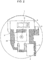
- Fig. 2 is a top view
- Fig. 3 is a left side view of the hydraulic excavator 1.
- a front working mechanism 5 which will be described later is omitted in Fig. 2 and Fig. 3 .
- the hydraulic excavator 1 has a lower travel base 2 having a crawler traveling mechanism, and a revolving upperstructure 3 mounted revolvably on the lower travel base 2.
- the revolving upperstructure 3 is equipped with a cab 4 for an operator aboard the hydraulic excavator to operate the machine, and the front working mechanism 5 is mounted as a working mechanism for work of earth/soil excavation and/or the like.
- An illustration and details of the front working mechanism 5 are omitted because the specific structure of the front working mechanism is well known.
- the hydraulic excavator 1 which is the industrial machine operates the lower travel base 2 for traveling, the revolving upperstructure 3 for revolving and the front working mechanism 5 to perform the work.
- Each of the above-described operating parts is driven by a hydraulic cylinder and/or a hydraulic motor, in which a movable section and a driving section to move the movable section form a movable mechanism.
- any other actuators such as an electric motor and/or the like may be used.
- the movable mechanism of the hydraulic excavator 1 is operated by the operator, and the cab 4 is installed in a forward position of the revolving upperstructure 3.
- a facility 6 including a machine room is located rearward of the cab 4 and the front working mechanism 5 which are arranged in an approximately side-by-side positon on the revolving upperstructure 3 to which the front working mechanism 5 is mounted, thus forming a revolving upperstructure main unit 3a.
- a counterweight 7 is placed at the tail end.
- the front working mechanism 5 includes a boom attached to the revolving upperstructure main unit 3a of the revolving upperstructure 3 to be capable of being raised/lowered, an arm coupled to the distal end of the boom to rotate in the vertical direction, and a bucket rotatably coupled to the distal end of the arm for work on earth/soil excavation and/or the like, the boom, the arm and the bucket being driven by the hydraulic cylinders, which are omitted from the drawings. Note that the specific structure of the front working mechanism 5 is well-known in the art.
- the revolving upperstructure main unit 3a is further equipped with a ladder 13 for the operator to get into/off the cab 4, and also a catwalk 14 forming a passage.
- the catwalk 14 is placed on the side of the revolving upperstructure main unit 3a and in a midpoint position in the vertical direction to be protruded in the lateral direction so that a position under the underside of the catwalk 14 is empty space.
- the ladder 13 is placed to be connected to the catwalk 14.
- the revolving upperstructure main unit 3a is formed of a frame structure, and the catwalk 14 and the ladder 13 are the jutting components extending out from the revolving upperstructure main unit 3a.
- the hydraulic excavator 1, having the movable mechanisms as described earlier, is equipped with a surround monitoring device for ensuring safety in the surrounding under operation conditions of the movable mechanism.
- the surround monitoring device is mounted to the revolving upperstructure 3 and includes a plurality of video cameras capable of shooting moving images. More specifically, in Fig. 4 and Fig. 5 , reference sign 15F denotes a front camera, reference sigh 15B denotes a rear camera, and reference signs 15L and 15R denote left-side and right-side cameras.
- the surrounding of the hydraulic excavator 1 is monitored through the cameras 15F, 15B, 15L and 15R.
- reference sign 15 is used when collectively calling the camera for camera-monitoring.
- the cameras 15F, 15B, 15L and 15R are mounted to the revolving upperstructure main unit 3a of the revolving upperstructure 3, and are placed at high elevations so that the optical axis of each camera is oriented in the downward or obliquely downward direction.
- an image captured by each of the cameras 15 results in a top-view image looking downwardly from above.
- Installation positions of the respective cameras 15 are determined to have a positional relationship to monitor all around the hydraulic excavator 1.
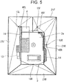
- Fig. 5 illustrates example placement of the cameras 15F, 15B, 15L and 15R.
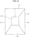
- the image captured by each camera 15F, 15B, 15L, 15R is displayed on a monitor 20 serving as an image displaying unit as illustrated in Fig. 6 .
- the monitor 20 is placed in a position within the cab 4 to allow the seated operator to visually check the monitor 20 from the operator's seat where the operator operates the hydraulic excavator 1.
- the images sent from the respective cameras 15F, 15B, 15L and 15R to be displayed on the monitor 20 are top-view images.
- the screen of the monitor 20 is split into a plurality of regions, such that the above-described top-view images are respectively trimmed to fit into the predetermined regions.
- camera images 21F, 21B, 21L and 21R are displayed on the respective display regions set in the monitor 20.
- a display region for an icon image 21C is set at the center of the screen, and a planar image of the hydraulic excavator 1 is symbolized and displayed in the display region of the icon image 21C as illustrated in Fig. 7 .
- the icon image 21C results from simplifying the hydraulic excavator which is the industrial machine of interest for monitoring, and in the drawing, the revolving upperstructure 3, the front working mechanism 5 and the catwalk 14 of the hydraulic excavator 1 are displayed. These components are designated with reference signs in Fig. 9 .
- Fig. 8 shows the configuration of a display controller 30 to control displaying of images in the monitor 20.
- the display controller 30 has an image correction unit 31.
- the image correction unit 31 performs common image signal processing, including aberration correction, contrast correction, color correction and/or the like, on the camera images sent from the respective cameras 15F, 15B, 15L and 15R, on the basis of camera optical system parameters and/or the like in order to improve the quality of each incoming image.
- the display controller 30 includes an image trimming unit 32, in which each of the camera images 21F, 21B, 21L and 21R captured by the respective cameras 15F, 15B, 15L and 15R is trimmed to a size and a shape to be displayed in the corresponding display region.
- the icon image 21 is displayed together with the camera images 21F, 21B, 21L and 21R of the four cameras.
- the icon image 21C is generated by an icon image generating unit 33.
- the individual camera images 21F, 21B, 21L and 21R and the icon image 21C are composited for displaying by an image compositing unit 33.
- the icon image 21C is displayed on a central position of the monitor 20, and the individual camera images 21F, 21B, 21L and 21R are arranged around the icon image 21C.
- the output data from the image compositing unit 34 is sent to a display image generating unit 35. By the output from the display image generating unit 34, the above-described images are assigned respectively to the corresponding positions to be displayed.
- the icon image 21C is also an image representing the hydraulic excavator 1 in a planar form. Therefore, the hydraulic excavator 1 and its surrounding circumstances are displayed in a planar form on the monitor 20, enabling the operator to recognize the circumstances during operation of the hydraulic excavator 1 with ease.
- Obstructions such as various members or mechanisms may be located in optical paths from the cameras 15 mounted to the revolving upperstructure 3 to the ground. Accordingly, images corresponding to the positions under such obstructions cannot be obtained. For example, regarding a section on the left side of the revolving upperstructure 3 on which the cab 4 is placed, there is a large empty space between the ground contacting the crawler track belt which constitutes the tread of the lower travel base 2 and the position of the underside of the cab 4. Further, because the catwalk 14 and the ladder 13 are located rearward of the cab 4, there is a wide empty space under the undersides of them.
- the empty spaces contain a spacious hidden area existing due to the cab 4, catwalk 14, ladder 13 and/or the like.
- the operator, other workers and/or the like may possibly enter such hidden-area spaces, but also tools and other equipment may be placed within such hidden-area spaces.
- a support arm 40L is provided to jut from the revolving upperstructure main unit 3a in the lateral direction, so that the camera 15L photographing the region is not mounted to the revolving upperstructure main unit 3a and instead the camera 15L is supported at the distal end of the support arm 40L.
- the optical axis of the camera 15L mounted at the support arm 40L is located outward of the outer side of the catwalk 14 by dimension p.
- the camera 15L is located at a height h above the ground. Because of this, at a level of and around the ground surface, the camera 15L is able to have a field of view covering virtually the crawler belt forming part of the lower travel base 2.
- the field of view of the camera 15L is able to cover the position under the underside of the catwalk 14.
- the right camera 15R and the front camera 15F are mounted to support arms 40R and 40F each of which juts from the revolving upperstructure main unit 3a in a predetermined direction, increasing the field of view for the sections.
- the character image 21C is displayed with a range resulting from an increase in the field of view being in a transparent state.
- the symbol image of the hydraulic excavator 1 displayed in the icon image 21C includes a part in the transparent state, but the outside shape of the hydraulic excavator 1 is displayed in outline. Accordingly, in the following description, reference sign 40 is used to correctively call the support arm.
- the installation position and the jutting length of the support arm 40 can be determined as appropriate on the basis of the structure of the revolving upperstructure 3.
- the jutting length is determined with reference to a revolving radius R shown in Fig. 2 , and as long as the jutting length is within the revolving radius R, even if the support arm 40 juts greatly from the revolving upperstructure main unit 3a, there is no possibility of the support arm 40 coming into collision with other substance, and the like.
- the support arm 40 is preferably formed of rigid body, so that the camera 15 is firmly fixed to the support arm 40 in order to prevent the camera 15 from being displaced from its normal position by vibration and/or the like.
- the support arm 40L for the camera 15L mounted on the left side extends in the lateral direction and the support arms 40F and 40R for the cameras 15F and 15R extend in the forward direction, but the extending direction can be determined based on the position of the hidden area to be displayed on the monitor 20.
- the camera 15B is located in a position on an upper portion of the counterweight 7 without an extra support arm.
- the camera 15B may be supported by a support arm.
- the structure designed as described above enables displaying of the hidden sections covered with the revolving upperstructure 3, such as the position under the underside of the catwalk 14 and the like, as well as the sections of the surrounding of the hydraulic excavator 1 on the monitor 20.
- the revolving upperstructure 3 with the camera 15 mounted thereto even if a section is out of the field of view, the section where a worker and the like may possibly enter is able to be displayed on the monitor 20, enhancing the effectiveness as the surround monitoring.
- the hidden area transparently displayed is a section where a person and the like may possibly enter. There's no need to display, for example, a section where a person and the like may not enter such as the tread of the crawler belt and the like. Accordingly, the level position and the jutting length of the support arm 40 to which the camera 15 is mounted may be determined as appropriate on the basis of the position and expanse of a hidden area which is required to be transparently displayed.
- the hydraulic excavator 1 is used for work on earth/soil excavation and the like, and the front working mechanism 5 is operated.
- the front working mechanism 5 When the front working mechanism 5 is operated for earth/soil excavation, the bucket attached at the distal end is driven from above to cut deep into the earth. Because of this, if a person or a substance is located within the range of motion track of the bucket, the bucket may possibly collide with the person or substance.
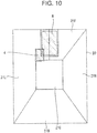
- the monitor 20 is designed to display, as an excavatable range B, a range in which the bucket can make contact with the ground within the reach range of the front working mechanism 5.
- the front working mechanism 5 is mounted to the revolving upperstructure 3, so that the front working mechanism 5 revolves in synchronism with the revolving upperstructure 3 when the revolving upperstructure 3 is operated to revolve. Then, the monitoring cameras 15F, 15B, 15L and 15R are also mounted to the revolving upperstructure 3, so that no change occurs in the positional relationship with the front working mechanism 5 on the images captured by the cameras 15F, 15B, 15L and 15R.
- the buckets are of a plurality of types of varying width dimension.
- the excavatable range B is desirably varied according to the structure of the front working mechanism 5 actually mounted to the hydraulic excavator 12.
- displaying an excavatable range B on the monitor 20 enables the driving of the hydraulic excavator 1 with reference to the excavatable range B when the hydraulic excavator 1 is travelled and revolved to select an excavation site, facilitating positional adjustment for excavation site.
- displaying the excavatable range B on the monitor 20 offers enhanced work efficiencies as well as the ensuring of work safety.
Landscapes
- Engineering & Computer Science (AREA)
- Multimedia (AREA)
- Mining & Mineral Resources (AREA)
- Civil Engineering (AREA)
- General Engineering & Computer Science (AREA)
- Structural Engineering (AREA)
- Theoretical Computer Science (AREA)
- Physics & Mathematics (AREA)
- General Physics & Mathematics (AREA)
- Signal Processing (AREA)
- Mechanical Engineering (AREA)
- Component Parts Of Construction Machinery (AREA)
- Closed-Circuit Television Systems (AREA)
Abstract
Description
- The present invention relates to a monitoring image display device of an industrial machine, such as, in particular, a large hydraulic excavator for mining, a dump truck, a road construction machine, and the like, to monitor the surroundings of the industrial machine during operation.
- As the industrial machine, for example, a hydraulic excavator has a lower travel base and a revolving upperstructure which is revolvably coupled to the lower travel base. The revolving upperstructure is equipped with a front working mechanism as a working mechanism. The front working mechanism has a boom and an arm. The boom is mounted to the revolving upperstructure in such a manner as to be raised/lowered. The arm is vertically rotatably coupled to the distal end of the boom. The distal end of the arm is equipped with a front attachment. The front attachment is a bucket when used in excavation work.
- It is well known in the art to provide a surround monitoring device to monitor the surrounding circumstances of the revolving upperstructure in order to ensure work safety while the front working mechanism serving as the working mechanism is driven to carry out earth/soil excavation work and/or the like. The surround monitoring device is configured to include a camera mounted to the revolving upperstructure, and a monitor placed, within a cab, in front of the operator seat in which the operator is to sit. Images taken by the camera are displayed on the monitor screen in the form of moving images. Also, ensuring the safety during traveling of the hydraulic excavator and during excavation work or the like, and the like, requires the field of view covering the rear and both the left and right sides of the revolving upperstructure. In order to provide a wide-angle field of view around the hydraulic excavator which is the industrial machinery, the revolving upperstructure equipped with a plurality of cameras is conventionally used. This eliminates blind spots from almost all around the revolving upperstructure, ensuring the work safety and improving the maneuverability of the industrial machine.
-
Patent Literature 1 discloses the configuration in which view transformation processing is applied to images of the surroundings of the industrial machine captured by a plurality of cameras for a view from above so that the images are displayed as two-dimensionally-projected top-view monitoring images on the monitor screen. With the configuration inPatent Literature 1, the plurality of cameras are mounted to the revolving upperstructure of the hydraulic excavator and the images of the respective cameras are combined on the monitor screen in order to obtain the surround monitoring image. - The cameras are mounted in three locations, in a position in a rear portion of and positions in the right and left side portions of the hydraulic excavator, in which the optical axis of the imaging lens of each of the cameras is directed in an obliquely downward direction. An image taken by each camera is a through image, so that the view transformation processing is applied to the through image to obtain a monitoring image. The view after the transformation is a view from above, thereby obtaining the three top-view images projected from above the hydraulic excavator.
- With this configuration, the top-view images are displayed on the monitor screen, in which an image illustration symbolically showing the hydraulic excavator (specifically, a plane image illustration of the hydraulic excavator) is displayed on the monitor screen and the top-view images captured by the respective cameras are arranged around the image illustration. More specifically, the image illustration is displayed on a central position of the monitor screen and the top-view images are arranged respectively in regions on the rear side and the left and right sides of the image illustration, resulting in displaying the bird's-eye view image for surround monitoring.
- Patent Literature 1:
Japanese Patent Application Laid-Open No. 2010-204821 - Such a hydraulic excavator is also used for mining in a mine. The hydraulic excavator for mining, which is very large in size, is structured to include a crawler-type lower travel base having left and right crawler belts. The revolving upperstructure installed through a revolving apparatus onto the lower travel base is located at a height of 1.8 meters or more from ground level.
In this manner, the cameras are mounted to the revolving upperstructure and a large empty space exists in a position under the underside of a vehicle frame of the revolving upperstructure. In the situation in which a worker working around the hydraulic excavator enters the space under the underside of the vehicle frame of the revolving upperstructure, the worker may possibly not be captured within the field of view of the surround-monitoring camera. - Enhancing the effectiveness of the monitoring of the surrounding to the industrial machine involves a lessening of the section of blind spot of the monitoring camera, and it is desired for this purpose that the blind spot is absent. Locations of interest to be monitored do not include, understandably, a location at a distance from the industrial machine where the operation of the industrial machine is not affected, a space-limited location where a worker and the like cannot enter, and the tread of the crawler band forming part of the lower travel base which touches the ground. However, especially, for a large/heavy industrial machine, there is a necessity to cause the field of view of the monitor cameras to cover the areas under the underside of the frame of the revolving upperstructure and the section extending out from the frame to the extent possible.
- The present invention has been made in light of the aforementioned points and it is an object of the invention to expand the range of the field of view of the monitoring cameras for a further enhancement in the effectiveness of surround monitoring.
- To address the aforementioned technical problems, the present invention provides a monitoring image display device installed on an industrial machine which has a movable mechanism provided at least in a part, the monitoring image display device including: one or more monitoring cameras which are placed in a location at least partially extending beyond an outline region to have a field of view covering the surroundings of the industrial machine; an image generating unit that generates top-view images captured by the monitoring cameras looking downward from above; an icon-image generating unit that generates an icon image representing a plane of the industrial machine with at least the outline being shown in a graphic form; an image compositing unit that performs composite processing to display an image captured by the image generating unit around the icon image generated by the icon-image generating unit; and an image display unit that displays the top-view images composited by the image compositing unit to include part of a section hidden within a display region of the icon image.
- The monitoring image display device of the industrial machine according to the present invention is a device used in an industrial machine to check for safety of the surroundings of the industrial machine during its operation, and the industrial machine has a movable mechanism mounted to at least a part thereof. Specifically, the movable mechanism includes a working mechanism, traveling mechanism and/or the like. For safe operation of the movable mechanism structured as described above, monitoring using images is performed. The images are displayed on the image display unit, namely, the monitor. As display mode, a plane image of the industrial machine is displayed as an icon image. The icon image is represented in an outline.
- Images captured by the monitoring cameras, together with the icon image, are displayed. Therefore, the images of the monitoring cameras are top-view images. For the purpose, the monitoring cameras are located at high elevations so that the optical axis is oriented downward so as to obtain a top-view image. The monitoring cameras are designed to be placed in at least one location or a plurality of locations, and four or more monitoring cameras are preferably mounted in order to photograph the overall surroundings of the industrial machine. The plurality of monitoring cameras are arranged such that their fields of view overlap each other, and the images are trimmed for display with continuity between adjacent images.
- Because of the structure of the industrial machine, an empty space is created in an underside position in the outside shape of the industrial machine. For example, a large hydraulic excavator, which is an industrial machine, is equipped with a catwalk for the passage of the operator and the like. The catwalk is provided as a structure to jut outward from the frame of the revolving upperstructure. In order to monitor the area under the underside of the catwalk, an image of a section hidden within the icon image is also displayed.
- The monitoring cameras are sited at high elevations for sections forming the outside shape of the machine, such as the catwalk and the like. In addition, the monitoring cameras are placed in positions jutting outward relative to the outline of the structure. This enables displaying a ground surface image including the sections positioned inward of the outside shape. A further increase in the field of view toward the center involves a further increase in height of the camera position to exceed the section defining the outside shape, and also a further increase in length of jutting from the outside shape. However, an increase in the amount of jutting upward and forward correspondingly increases the possibility of collision with any other substance. Accordingly, the amount of jutting is limited.
- In a machine with a revolving upperstructure revolvably mounted on a lower travel base as in the case of the hydraulic excavator, a revolving radius of the revolving upperstructure is determined as a critical position of the jutting length of the position at which the camera is mounted. For safe revolving, a collision with other substance and/or the like must be avoided within the revolving radius of the revolving upperstructure. During operation, other substance and the like are prevented from entering the area within the revolving radius. As a result, the critical position of the jutting length of the mounting position of the camera is able to be determined within the revolving radius of the revolving upperstructure. Then, a support arm is installed to a predetermined position of a revolving upperstructure main unit forming part of the revolving upperstructure of the hydraulic excavator, so that the camera is mounted to the distal end of the support arm. The support arm may be structured to be adjustable in length in order to make the mounting position of the camera adjustable. However, if strong vibrations may be created such as in the hydraulic excavator, the mounting position of the camera must be prevented from being displaced. Because of this, the support arm is desirably installed in a rigid manner.
- Next, the hydraulic excavator includes a front working mechanism as a working mechanism installed to the revolving upperstructure for earth/soil excavation. The front working mechanism includes a boom attached to the revolving frame of the revolving upperstructure to be capable of being raised/lowered, an arm coupled to the distal end of the boom to be rotatable in the vertical direction, and a bucket coupled to the distal end of the arm via an articulated mechanism. During excavation, the bucket is engaged into the ground. Accordingly, during excavation operation, the section in which the bucket makes contact with the ground is a danger region which any other vehicle and worker must be prevented from entering.
- For this reason, when the hydraulic excavator is in a predetermined position, that is, when the revolving upperstructure is in a position at a predetermined angle, it is important in terms of work safety that the region in which excavation using the bucket will be carried out is displayed on the monitor. In particular, when doing the excavation work by remote control without the operator aboard, displaying the location of interest for excavation on the monitor is critical in terms of work safety and efficiency.
- In the industrial machine such as the hydraulic excavator and the like, a decrease in blind spots in an image displayed on the monitor provides a higher level of work safety.
-
- [
Fig. 1] Fig. 1 is a front view of a hydraulic excavator as an example of the industrial machine. - [
Fig. 2] Fig. 2 is a top view of the hydraulic excavator inFig. 1 . - [
Fig. 3] Fig. 3 is a left side view of the hydraulic excavator inFig. 1 . - [
Fig. 4] Fig. 4 is a schematic illustration of the field of view of cameras when viewed from a position inFig. 3 . - [
Fig. 5] Fig. 5 is a schematic illustration of the field of view of cameras when viewed from a position inFig. 2 . - [
Fig. 6] Fig. 6 is a diagram illustrating an example of a display region of each image on the screen of a monitor. - [
Fig. 7] Fig. 7 is a top view illustrating an example of an icon image displayed on the monitor. - [
Fig. 8] Fig. 8 is a block diagram illustrating the configuration of a display controller of the monitor. - [
Fig. 9] Fig. 9 is an illustration describing the principles for making a hidden area under the underside of a catwalk visible to the camera to fall within the angle of view of the camera. - [
Fig. 10] Fig. 10 is an illustration showing another example mode of an image on a monitor including an excavatable range by a bucket. - Embodiments according to the present invention will now be described with reference to the accompanying drawings. First,
Fig. 1 to Fig. 3 illustrate the structure of ahydraulic excavator 1 as an example of the industrial machine.Fig. 1 is a front view,Fig. 2 is a top view andFig. 3 is a left side view of thehydraulic excavator 1. Here, afront working mechanism 5 which will be described later is omitted inFig. 2 andFig. 3 . - The
hydraulic excavator 1 has alower travel base 2 having a crawler traveling mechanism, and a revolvingupperstructure 3 mounted revolvably on thelower travel base 2. The revolvingupperstructure 3 is equipped with acab 4 for an operator aboard the hydraulic excavator to operate the machine, and thefront working mechanism 5 is mounted as a working mechanism for work of earth/soil excavation and/or the like. An illustration and details of thefront working mechanism 5 are omitted because the specific structure of the front working mechanism is well known. - Thus, the
hydraulic excavator 1 which is the industrial machine operates thelower travel base 2 for traveling, the revolvingupperstructure 3 for revolving and thefront working mechanism 5 to perform the work. Each of the above-described operating parts is driven by a hydraulic cylinder and/or a hydraulic motor, in which a movable section and a driving section to move the movable section form a movable mechanism. Also, any other actuators such as an electric motor and/or the like may be used. - The movable mechanism of the
hydraulic excavator 1 is operated by the operator, and thecab 4 is installed in a forward position of the revolvingupperstructure 3. On the right side of thecab 4, afacility 6 including a machine room is located rearward of thecab 4 and thefront working mechanism 5 which are arranged in an approximately side-by-side positon on the revolvingupperstructure 3 to which thefront working mechanism 5 is mounted, thus forming a revolving upperstructuremain unit 3a. Further, acounterweight 7 is placed at the tail end. - The
front working mechanism 5 includes a boom attached to the revolving upperstructuremain unit 3a of the revolvingupperstructure 3 to be capable of being raised/lowered, an arm coupled to the distal end of the boom to rotate in the vertical direction, and a bucket rotatably coupled to the distal end of the arm for work on earth/soil excavation and/or the like, the boom, the arm and the bucket being driven by the hydraulic cylinders, which are omitted from the drawings. Note that the specific structure of thefront working mechanism 5 is well-known in the art. - The revolving upperstructure
main unit 3a is further equipped with aladder 13 for the operator to get into/off thecab 4, and also acatwalk 14 forming a passage. Thecatwalk 14 is placed on the side of the revolving upperstructuremain unit 3a and in a midpoint position in the vertical direction to be protruded in the lateral direction so that a position under the underside of thecatwalk 14 is empty space. Further, theladder 13 is placed to be connected to thecatwalk 14. In this connection, the revolving upperstructuremain unit 3a is formed of a frame structure, and thecatwalk 14 and theladder 13 are the jutting components extending out from the revolving upperstructuremain unit 3a. - The
hydraulic excavator 1, having the movable mechanisms as described earlier, is equipped with a surround monitoring device for ensuring safety in the surrounding under operation conditions of the movable mechanism. The surround monitoring device is mounted to the revolvingupperstructure 3 and includes a plurality of video cameras capable of shooting moving images. More specifically, inFig. 4 andFig. 5 ,reference sign 15F denotes a front camera,reference sigh 15B denotes a rear camera, andreference signs hydraulic excavator 1 is monitored through thecameras
Incidentally, in the following description, reference sign 15 is used when collectively calling the camera for camera-monitoring. - The
cameras main unit 3a of the revolvingupperstructure 3, and are placed at high elevations so that the optical axis of each camera is oriented in the downward or obliquely downward direction. Thus, as shown inFig. 4 , an image captured by each of the cameras 15 results in a top-view image looking downwardly from above. Installation positions of the respective cameras 15 are determined to have a positional relationship to monitor all around thehydraulic excavator 1.Fig. 5 illustrates example placement of thecameras - As described above, the image captured by each
camera monitor 20 serving as an image displaying unit as illustrated inFig. 6 . Here, themonitor 20 is placed in a position within thecab 4 to allow the seated operator to visually check themonitor 20 from the operator's seat where the operator operates thehydraulic excavator 1. - The images sent from the
respective cameras monitor 20 are top-view images. The screen of themonitor 20 is split into a plurality of regions, such that the above-described top-view images are respectively trimmed to fit into the predetermined regions. As a result,camera images monitor 20. Then, a display region for anicon image 21C is set at the center of the screen, and a planar image of thehydraulic excavator 1 is symbolized and displayed in the display region of theicon image 21C as illustrated inFig. 7 . Here, theicon image 21C results from simplifying the hydraulic excavator which is the industrial machine of interest for monitoring, and in the drawing, the revolvingupperstructure 3, thefront working mechanism 5 and thecatwalk 14 of thehydraulic excavator 1 are displayed. These components are designated with reference signs inFig. 9 . -
Fig. 8 shows the configuration of adisplay controller 30 to control displaying of images in themonitor 20. Thedisplay controller 30 has animage correction unit 31. Theimage correction unit 31 performs common image signal processing, including aberration correction, contrast correction, color correction and/or the like, on the camera images sent from therespective cameras - Because the
monitor 20 provides the assignment display using the display regions for thecamera images display controller 30 includes animage trimming unit 32, in which each of thecamera images respective cameras - On the
monitor 20 the icon image 21 is displayed together with thecamera images icon image 21C is generated by an iconimage generating unit 33. Then, theindividual camera images icon image 21C are composited for displaying by animage compositing unit 33. Theicon image 21C is displayed on a central position of themonitor 20, and theindividual camera images icon image 21C. The output data from theimage compositing unit 34 is sent to a displayimage generating unit 35. By the output from the displayimage generating unit 34, the above-described images are assigned respectively to the corresponding positions to be displayed. - Because the
cameras icon image 21C is also an image representing thehydraulic excavator 1 in a planar form. Therefore, thehydraulic excavator 1 and its surrounding circumstances are displayed in a planar form on themonitor 20, enabling the operator to recognize the circumstances during operation of thehydraulic excavator 1 with ease. - Obstructions such as various members or mechanisms may be located in optical paths from the cameras 15 mounted to the revolving
upperstructure 3 to the ground. Accordingly, images corresponding to the positions under such obstructions cannot be obtained. For example, regarding a section on the left side of the revolvingupperstructure 3 on which thecab 4 is placed, there is a large empty space between the ground contacting the crawler track belt which constitutes the tread of thelower travel base 2 and the position of the underside of thecab 4. Further, because thecatwalk 14 and theladder 13 are located rearward of thecab 4, there is a wide empty space under the undersides of them. This means that, when viewing the revolvingupperstructure 3 in top view, the empty spaces contain a spacious hidden area existing due to thecab 4,catwalk 14,ladder 13 and/or the like. In addition, not only the operator, other workers and/or the like may possibly enter such hidden-area spaces, but also tools and other equipment may be placed within such hidden-area spaces. Further, in a heavier hydraulic excavator, there is room enough for accommodating a vehicle and/or the like. Accordingly, in terms of monitoring around thehydraulic excavator 1, it is desirable that the above-described empty space of the hidden area falls within the field of view of the monitoring camera. - Given these circumstances, as illustrated in
Fig. 9 , asupport arm 40L is provided to jut from the revolving upperstructuremain unit 3a in the lateral direction, so that thecamera 15L photographing the region is not mounted to the revolving upperstructuremain unit 3a and instead thecamera 15L is supported at the distal end of thesupport arm 40L. Accordingly, the optical axis of thecamera 15L mounted at thesupport arm 40L is located outward of the outer side of thecatwalk 14 by dimension p. Further, thecamera 15L is located at a height h above the ground. Because of this, at a level of and around the ground surface, thecamera 15L is able to have a field of view covering virtually the crawler belt forming part of thelower travel base 2. In addition, because thecamera 15L is placed forward of the position of thecatwalk 14 with theladder 13 mounted thereto, the field of view of thecamera 15L is able to cover the position under the underside of thecatwalk 14. - Likewise, the
right camera 15R and thefront camera 15F are mounted to supportarms main unit 3a in a predetermined direction, increasing the field of view for the sections. Further, on themonitor 20, thecharacter image 21C is displayed with a range resulting from an increase in the field of view being in a transparent state. In this case, the symbol image of thehydraulic excavator 1 displayed in theicon image 21C includes a part in the transparent state, but the outside shape of thehydraulic excavator 1 is displayed in outline. Accordingly, in the following description, reference sign 40 is used to correctively call the support arm. - In this manner, mounting the camera 15 to the distal end of the support arm 40 provided to jut from the revolving upperstructure
main unit 3a enables the field of view covering the hidden area of the revolvingupperstructure 3. In this respect, the installation position and the jutting length of the support arm 40 can be determined as appropriate on the basis of the structure of the revolvingupperstructure 3. The jutting length is determined with reference to a revolving radius R shown inFig. 2 , and as long as the jutting length is within the revolving radius R, even if the support arm 40 juts greatly from the revolving upperstructuremain unit 3a, there is no possibility of the support arm 40 coming into collision with other substance, and the like. The support arm 40 is preferably formed of rigid body, so that the camera 15 is firmly fixed to the support arm 40 in order to prevent the camera 15 from being displaced from its normal position by vibration and/or the like. - Here, in an example embodiment according to the present invention, the
support arm 40L for thecamera 15L mounted on the left side extends in the lateral direction and thesupport arms cameras monitor 20. In the illustrated case, thecamera 15B is located in a position on an upper portion of thecounterweight 7 without an extra support arm. However, thecamera 15B may be supported by a support arm. - The structure designed as described above enables displaying of the hidden sections covered with the revolving
upperstructure 3, such as the position under the underside of thecatwalk 14 and the like, as well as the sections of the surrounding of thehydraulic excavator 1 on themonitor 20. In addition, in the revolvingupperstructure 3 with the camera 15 mounted thereto, even if a section is out of the field of view, the section where a worker and the like may possibly enter is able to be displayed on themonitor 20, enhancing the effectiveness as the surround monitoring. - In the position under the underside of the revolving upperstructure
main unit 3a forming part of the revolvingupperstructure 3, the hidden area transparently displayed is a section where a person and the like may possibly enter. There's no need to display, for example, a section where a person and the like may not enter such as the tread of the crawler belt and the like. Accordingly, the level position and the jutting length of the support arm 40 to which the camera 15 is mounted may be determined as appropriate on the basis of the position and expanse of a hidden area which is required to be transparently displayed. - On the other hand, the
hydraulic excavator 1 is used for work on earth/soil excavation and the like, and thefront working mechanism 5 is operated. When thefront working mechanism 5 is operated for earth/soil excavation, the bucket attached at the distal end is driven from above to cut deep into the earth. Because of this, if a person or a substance is located within the range of motion track of the bucket, the bucket may possibly collide with the person or substance. During the work, there is a necessity to protect the person, substance and/or the like from collision with thefront working mechanism 5. Naturally, the operator aboard thecab 4 can visually recognize the motion of the front working mechanism. Given these circumstances, as illustrated inFig. 10 , themonitor 20 is designed to display, as an excavatable range B, a range in which the bucket can make contact with the ground within the reach range of thefront working mechanism 5. - The
front working mechanism 5 is mounted to the revolvingupperstructure 3, so that thefront working mechanism 5 revolves in synchronism with the revolvingupperstructure 3 when the revolvingupperstructure 3 is operated to revolve. Then, themonitoring cameras upperstructure 3, so that no change occurs in the positional relationship with thefront working mechanism 5 on the images captured by thecameras front working mechanism 5 can make contact with the ground, together with thecamera images icon image 21C, is displayed on themonitor 20, in which the excavatable range B is determined on the basis of the width dimension of the bucket and the maximum reach length. The buckets are of a plurality of types of varying width dimension. For this reason, the excavatable range B is desirably varied according to the structure of thefront working mechanism 5 actually mounted to the hydraulic excavator 12. - In this manner, displaying an excavatable range B on the
monitor 20 enables the driving of thehydraulic excavator 1 with reference to the excavatable range B when thehydraulic excavator 1 is travelled and revolved to select an excavation site, facilitating positional adjustment for excavation site. As a result, displaying the excavatable range B on themonitor 20 offers enhanced work efficiencies as well as the ensuring of work safety. -
- 1
- Hydraulic excavator
- 2
- Lower travel base
- 3
- Revolving upperstructure
- 3a
- Revolving upperstructure main unit
- 4
- Cabin
- 5
- Front working mechanism
- 15, 15F, 15B, 15L, 15R
- Camera
- 20
- Monitor
- 21, 21F, 21B, 21L, 21R
- Camera image
- 21C
- Icon image
Claims (3)
- A monitoring image display device of an industrial machine, comprising:one or more monitoring cameras (15, 15F, 15B, 15L, 15R) installed on the industrial machine (1) having a movable mechanism provided at least in part, and placed in a location at least partially extending beyond an outline region to have a field of view covering the surroundings of the industrial machine (1);an image generating unit (35) that generates top-view images captured by the monitoring cameras (15, 15F, 15B, 15L, 15R) looking downward from above;an icon-image generating unit (33) that generates an icon image (21C) representing a plane of the industrial machine (1) with at least outline being shown in a graphic form;an image compositing unit (34) that performs composite processing to display an image captured by the image generating unit (35) around the icon image (21C) generated by the icon-image generating unit (33); andan image display unit (20) that displays the top-view images composited by the image compositing unit to include part of a section hidden within a display region of the icon image (21C).
- The monitoring image display device of the industrial machine according to claim 1, wherein:the industrial machine (1) has a frame (3) capable of revolving;the icon image (21C) includes a region including the frame (3) and a projection extending outward from the frame (3), the region being displayed in an outline; andthe monitoring camera (15) is placed in a position upward of a section of the outline to jut outward from the outline.
- The display device of the industrial machine according to claim 1, wherein:the industrial machine (1) has a movable working mechanism (5) projecting beyond the frame (3); andthe icon image (21C) has a movable-range display region (B) for displaying a motion track of the working mechanism (5).
Applications Claiming Priority (2)
| Application Number | Priority Date | Filing Date | Title |
|---|---|---|---|
| JP2014027536A JP6095592B2 (en) | 2014-02-17 | 2014-02-17 | Monitoring image display device for hydraulic excavator |
| PCT/JP2015/051402 WO2015122245A1 (en) | 2014-02-17 | 2015-01-20 | Monitoring image display device of industrial machine |
Publications (3)
| Publication Number | Publication Date |
|---|---|
| EP3110142A1 true EP3110142A1 (en) | 2016-12-28 |
| EP3110142A4 EP3110142A4 (en) | 2017-11-29 |
| EP3110142B1 EP3110142B1 (en) | 2021-12-22 |
Family
ID=53799993
Family Applications (1)
| Application Number | Title | Priority Date | Filing Date |
|---|---|---|---|
| EP15748978.2A Active EP3110142B1 (en) | 2014-02-17 | 2015-01-20 | Monitoring image display device of industrial machine |
Country Status (7)
| Country | Link |
|---|---|
| US (2) | US20160217331A1 (en) |
| EP (1) | EP3110142B1 (en) |
| JP (1) | JP6095592B2 (en) |
| CN (1) | CN105493503B (en) |
| AU (1) | AU2015216409B2 (en) |
| CA (1) | CA2923033C (en) |
| WO (1) | WO2015122245A1 (en) |
Families Citing this family (31)
| Publication number | Priority date | Publication date | Assignee | Title |
|---|---|---|---|---|
| AU2016242761B2 (en) * | 2015-03-31 | 2019-08-08 | Komatsu Ltd. | Working machine |
| US9871968B2 (en) * | 2015-05-22 | 2018-01-16 | Caterpillar Inc. | Imaging system for generating a surround-view image |
| JP6713190B2 (en) * | 2015-10-09 | 2020-06-24 | 住友重機械工業株式会社 | Shovel operating device and shovel operating method |
| JP2017081238A (en) * | 2015-10-23 | 2017-05-18 | 株式会社小松製作所 | Display system and work vehicle |
| JP2017082415A (en) * | 2015-10-23 | 2017-05-18 | 株式会社小松製作所 | Display system |
| CN108431338B (en) | 2015-12-28 | 2020-12-11 | 住友建机株式会社 | Shovel |
| EP3246474B1 (en) * | 2016-03-29 | 2021-11-10 | Komatsu Ltd. | Work vehicle |
| JP6684682B2 (en) | 2016-08-18 | 2020-04-22 | 株式会社神戸製鋼所 | Construction machinery |
| US10070071B2 (en) * | 2016-08-30 | 2018-09-04 | Caterpillar Inc. | Method of imaging a machine environment and machine system implementing same |
| JP2018050119A (en) * | 2016-09-20 | 2018-03-29 | 国立大学法人 東京大学 | Display system of work vehicle |
| KR102454612B1 (en) * | 2016-11-01 | 2022-10-13 | 스미토모 겐키 가부시키가이샤 | Safety management system for construction machinery, management device |
| KR20180078970A (en) * | 2016-12-30 | 2018-07-10 | 화남전자 주식회사 | Camera Arranging Structure for Monitoring Surrounding Area of Construction Equipment |
| US10250812B2 (en) | 2017-05-17 | 2019-04-02 | Caterpillar Inc. | Display system for machine |
| US10889958B2 (en) * | 2017-06-06 | 2021-01-12 | Caterpillar Inc. | Display system for machine |
| CN111032958B (en) * | 2017-08-08 | 2023-03-10 | 住友建机株式会社 | road machinery |
| US10662603B2 (en) * | 2017-08-18 | 2020-05-26 | Independence Excavating, Inc. | Slope roller assembly |
| JP6958216B2 (en) * | 2017-10-17 | 2021-11-02 | 株式会社タダノ | Work vehicle |
| CN111052734B (en) | 2017-10-17 | 2021-06-01 | 株式会社多田野 | work vehicle |
| JP7143578B2 (en) * | 2017-10-17 | 2022-09-29 | 株式会社タダノ | work vehicle |
| US10883256B2 (en) * | 2018-05-25 | 2021-01-05 | Deere & Company | Object responsive control system for a work machine |
| CN109255335A (en) * | 2018-09-28 | 2019-01-22 | 广州希华通讯设备有限公司 | Identification monitoring system for construction site excavator |
| WO2021054757A1 (en) * | 2019-09-20 | 2021-03-25 | 주식회사 와이즈오토모티브 | Front image generation device for construction equipment |
| WO2021054756A1 (en) | 2019-09-20 | 2021-03-25 | 주식회사 와이즈오토모티브 | Front image generation device for heavy equipment |
| WO2021054758A1 (en) * | 2019-09-20 | 2021-03-25 | 주식회사 와이즈오토모티브 | Front image generation device for construction equipment |
| US11231501B2 (en) | 2019-09-26 | 2022-01-25 | Baidu Usa Llc | Front and side three-LIDAR design for autonomous driving vehicles |
| JP7491194B2 (en) * | 2020-11-23 | 2024-05-28 | 株式会社デンソー | Peripheral image generating device and display control method |
| JP7733563B2 (en) * | 2021-12-17 | 2025-09-03 | 日立建機株式会社 | Surroundings monitoring system for excavators |
| CN115013386B (en) * | 2022-05-30 | 2023-06-23 | 燕山大学 | Control method and control device of hydraulic system protection device based on visual recognition |
| US11898332B1 (en) * | 2022-08-22 | 2024-02-13 | Caterpillar Inc. | Adjusting camera bandwidth based on machine operation |
| CN116347240A (en) * | 2023-01-13 | 2023-06-27 | 北京天玛智控科技股份有限公司 | Video monitoring method, device, electronic equipment and medium for fully mechanized coal mining face |
| WO2025028603A1 (en) * | 2023-08-02 | 2025-02-06 | 住友重機械建機クレーン株式会社 | Crane |
Family Cites Families (18)
| Publication number | Priority date | Publication date | Assignee | Title |
|---|---|---|---|---|
| JP2913230B2 (en) * | 1991-10-23 | 1999-06-28 | 日立建機株式会社 | Lighting equipment for large construction machinery |
| JPH10237900A (en) * | 1997-02-28 | 1998-09-08 | Hitachi Constr Mach Co Ltd | Construction machine with ladder |
| JP4196368B2 (en) * | 1999-12-20 | 2008-12-17 | 株式会社小松製作所 | Construction equipment lifting ladder equipment |
| KR100892269B1 (en) * | 2001-06-15 | 2009-04-09 | 가부시키가이샤 고마쓰 세이사쿠쇼 | Construction machine |
| JP3980565B2 (en) * | 2004-02-16 | 2007-09-26 | 松下電器産業株式会社 | Driving assistance device |
| KR100966288B1 (en) * | 2009-01-06 | 2010-06-28 | 주식회사 이미지넥스트 | Around image generating method and apparatus |
| JP4951639B2 (en) | 2009-03-02 | 2012-06-13 | 日立建機株式会社 | Work machine with ambient monitoring device |
| JP5269026B2 (en) * | 2010-09-29 | 2013-08-21 | 日立建機株式会社 | Work machine ambient monitoring device |
| US9113047B2 (en) * | 2010-10-22 | 2015-08-18 | Hitachi Construction Machinery Co., Ltd. | Peripheral monitoring device for working machine |
| KR101735116B1 (en) * | 2011-01-24 | 2017-05-15 | 두산인프라코어 주식회사 | an Drive Information Recording Apparatus for a Construction Heavy Equipment |
| JPWO2012157438A1 (en) * | 2011-05-13 | 2014-07-31 | 日立建機株式会社 | Hydraulic excavator rear vision display |
| JP5779244B2 (en) * | 2011-05-13 | 2015-09-16 | 日立建機株式会社 | Work machine ambient monitoring device |
| JP2012252675A (en) * | 2011-06-07 | 2012-12-20 | Komatsu Ltd | Dump truck |
| JP5888956B2 (en) * | 2011-12-13 | 2016-03-22 | 住友建機株式会社 | Excavator and surrounding image display method of the excavator |
| AU2013208525A1 (en) * | 2012-01-12 | 2014-08-14 | Hitachi Construction Machinery Co., Ltd. | Periphery monitoring device for self-propelled industrial machine |
| JP5988683B2 (en) * | 2012-05-15 | 2016-09-07 | 日立建機株式会社 | Display device for self-propelled industrial machine |
| JP2013253402A (en) * | 2012-06-06 | 2013-12-19 | Hitachi Constr Mach Co Ltd | Surrounding monitoring device for work machine |
| CN104380724B (en) * | 2012-06-08 | 2017-09-12 | 日立建机株式会社 | The display device of self-propelled industrial machinery |
-
2014
- 2014-02-17 JP JP2014027536A patent/JP6095592B2/en active Active
-
2015
- 2015-01-20 CA CA2923033A patent/CA2923033C/en active Active
- 2015-01-20 WO PCT/JP2015/051402 patent/WO2015122245A1/en not_active Ceased
- 2015-01-20 EP EP15748978.2A patent/EP3110142B1/en active Active
- 2015-01-20 US US14/916,058 patent/US20160217331A1/en not_active Abandoned
- 2015-01-20 AU AU2015216409A patent/AU2015216409B2/en active Active
- 2015-01-20 CN CN201580001771.5A patent/CN105493503B/en active Active
-
2018
- 2018-10-12 US US16/158,346 patent/US10650251B2/en active Active
Also Published As
| Publication number | Publication date |
|---|---|
| JP6095592B2 (en) | 2017-03-15 |
| CA2923033A1 (en) | 2015-08-20 |
| EP3110142A4 (en) | 2017-11-29 |
| EP3110142B1 (en) | 2021-12-22 |
| US20160217331A1 (en) | 2016-07-28 |
| JP2015151794A (en) | 2015-08-24 |
| US10650251B2 (en) | 2020-05-12 |
| AU2015216409B2 (en) | 2017-10-19 |
| CN105493503B (en) | 2018-08-24 |
| US20190042858A1 (en) | 2019-02-07 |
| AU2015216409A1 (en) | 2016-03-17 |
| CN105493503A (en) | 2016-04-13 |
| WO2015122245A1 (en) | 2015-08-20 |
| CA2923033C (en) | 2021-01-12 |
Similar Documents
| Publication | Publication Date | Title |
|---|---|---|
| US10650251B2 (en) | Monitoring image display device of industrial machine | |
| CN107407078B (en) | Periphery monitoring device for working machine and periphery monitoring method for working machine | |
| JP6204884B2 (en) | Peripheral display device for swivel work machine | |
| KR101945421B1 (en) | Work-machine periphery monitoring device | |
| EP2717570A1 (en) | Device for monitoring area around working machine | |
| JP6106754B2 (en) | Work machine ambient monitoring device | |
| JP6029941B2 (en) | Image generator for paving machines | |
| CN104041018A (en) | Surrounding monitoring devices for self-propelled industrial machinery | |
| JP2013253402A (en) | Surrounding monitoring device for work machine | |
| EP2991343B1 (en) | Image to be processed generating device, image to be processed generating method, and operation assistance system | |
| EP3788205B1 (en) | System and method for selectively displaying image data in a working machine | |
| JP2017145649A (en) | Work machine | |
| US10186017B2 (en) | Construction machinery | |
| JP6256874B2 (en) | Overhead image display device for construction machinery | |
| JP7377626B2 (en) | construction machinery | |
| KR20170024295A (en) | Working machine | |
| CN115088251B (en) | Remote operation device, remote operation assistance server, remote operation assistance system and remote operation assistance method | |
| WO2020080294A1 (en) | Hydraulic excavator | |
| JP7807737B2 (en) | Image Generation System | |
| WO2025084139A1 (en) | Work machine and work system | |
| JP2025068500A (en) | Work machine and work system |
Legal Events
| Date | Code | Title | Description |
|---|---|---|---|
| PUAI | Public reference made under article 153(3) epc to a published international application that has entered the european phase |
Free format text: ORIGINAL CODE: 0009012 |
|
| STAA | Information on the status of an ep patent application or granted ep patent |
Free format text: STATUS: REQUEST FOR EXAMINATION WAS MADE |
|
| 17P | Request for examination filed |
Effective date: 20160315 |
|
| AK | Designated contracting states |
Kind code of ref document: A1 Designated state(s): AL AT BE BG CH CY CZ DE DK EE ES FI FR GB GR HR HU IE IS IT LI LT LU LV MC MK MT NL NO PL PT RO RS SE SI SK SM TR |
|
| AX | Request for extension of the european patent |
Extension state: BA ME |
|
| DAX | Request for extension of the european patent (deleted) | ||
| A4 | Supplementary search report drawn up and despatched |
Effective date: 20171027 |
|
| RIC1 | Information provided on ipc code assigned before grant |
Ipc: H04N 7/18 20060101AFI20171023BHEP Ipc: E02F 9/26 20060101ALI20171023BHEP Ipc: E02F 9/24 20060101ALI20171023BHEP Ipc: B60R 1/00 20060101ALI20171023BHEP Ipc: G06T 11/60 20060101ALI20171023BHEP |
|
| GRAJ | Information related to disapproval of communication of intention to grant by the applicant or resumption of examination proceedings by the epo deleted |
Free format text: ORIGINAL CODE: EPIDOSDIGR1 |
|
| GRAP | Despatch of communication of intention to grant a patent |
Free format text: ORIGINAL CODE: EPIDOSNIGR1 |
|
| GRAP | Despatch of communication of intention to grant a patent |
Free format text: ORIGINAL CODE: EPIDOSNIGR1 |
|
| STAA | Information on the status of an ep patent application or granted ep patent |
Free format text: STATUS: GRANT OF PATENT IS INTENDED |
|
| INTG | Intention to grant announced |
Effective date: 20210701 |
|
| INTG | Intention to grant announced |
Effective date: 20210705 |
|
| GRAS | Grant fee paid |
Free format text: ORIGINAL CODE: EPIDOSNIGR3 |
|
| GRAA | (expected) grant |
Free format text: ORIGINAL CODE: 0009210 |
|
| STAA | Information on the status of an ep patent application or granted ep patent |
Free format text: STATUS: THE PATENT HAS BEEN GRANTED |
|
| AK | Designated contracting states |
Kind code of ref document: B1 Designated state(s): AL AT BE BG CH CY CZ DE DK EE ES FI FR GB GR HR HU IE IS IT LI LT LU LV MC MK MT NL NO PL PT RO RS SE SI SK SM TR |
|
| REG | Reference to a national code |
Ref country code: GB Ref legal event code: FG4D |
|
| REG | Reference to a national code |
Ref country code: CH Ref legal event code: EP |
|
| REG | Reference to a national code |
Ref country code: DE Ref legal event code: R096 Ref document number: 602015075934 Country of ref document: DE |
|
| REG | Reference to a national code |
Ref country code: AT Ref legal event code: REF Ref document number: 1457851 Country of ref document: AT Kind code of ref document: T Effective date: 20220115 |
|
| REG | Reference to a national code |
Ref country code: IE Ref legal event code: FG4D |
|
| REG | Reference to a national code |
Ref country code: LT Ref legal event code: MG9D |
|
| PG25 | Lapsed in a contracting state [announced via postgrant information from national office to epo] |
Ref country code: RS Free format text: LAPSE BECAUSE OF FAILURE TO SUBMIT A TRANSLATION OF THE DESCRIPTION OR TO PAY THE FEE WITHIN THE PRESCRIBED TIME-LIMIT Effective date: 20211222 Ref country code: LT Free format text: LAPSE BECAUSE OF FAILURE TO SUBMIT A TRANSLATION OF THE DESCRIPTION OR TO PAY THE FEE WITHIN THE PRESCRIBED TIME-LIMIT Effective date: 20211222 Ref country code: FI Free format text: LAPSE BECAUSE OF FAILURE TO SUBMIT A TRANSLATION OF THE DESCRIPTION OR TO PAY THE FEE WITHIN THE PRESCRIBED TIME-LIMIT Effective date: 20211222 Ref country code: BG Free format text: LAPSE BECAUSE OF FAILURE TO SUBMIT A TRANSLATION OF THE DESCRIPTION OR TO PAY THE FEE WITHIN THE PRESCRIBED TIME-LIMIT Effective date: 20220322 |
|
| REG | Reference to a national code |
Ref country code: NL Ref legal event code: MP Effective date: 20211222 |
|
| REG | Reference to a national code |
Ref country code: AT Ref legal event code: MK05 Ref document number: 1457851 Country of ref document: AT Kind code of ref document: T Effective date: 20211222 |
|
| PG25 | Lapsed in a contracting state [announced via postgrant information from national office to epo] |
Ref country code: SE Free format text: LAPSE BECAUSE OF FAILURE TO SUBMIT A TRANSLATION OF THE DESCRIPTION OR TO PAY THE FEE WITHIN THE PRESCRIBED TIME-LIMIT Effective date: 20211222 Ref country code: NO Free format text: LAPSE BECAUSE OF FAILURE TO SUBMIT A TRANSLATION OF THE DESCRIPTION OR TO PAY THE FEE WITHIN THE PRESCRIBED TIME-LIMIT Effective date: 20220322 Ref country code: LV Free format text: LAPSE BECAUSE OF FAILURE TO SUBMIT A TRANSLATION OF THE DESCRIPTION OR TO PAY THE FEE WITHIN THE PRESCRIBED TIME-LIMIT Effective date: 20211222 Ref country code: HR Free format text: LAPSE BECAUSE OF FAILURE TO SUBMIT A TRANSLATION OF THE DESCRIPTION OR TO PAY THE FEE WITHIN THE PRESCRIBED TIME-LIMIT Effective date: 20211222 Ref country code: GR Free format text: LAPSE BECAUSE OF FAILURE TO SUBMIT A TRANSLATION OF THE DESCRIPTION OR TO PAY THE FEE WITHIN THE PRESCRIBED TIME-LIMIT Effective date: 20220323 |
|
| PG25 | Lapsed in a contracting state [announced via postgrant information from national office to epo] |
Ref country code: NL Free format text: LAPSE BECAUSE OF FAILURE TO SUBMIT A TRANSLATION OF THE DESCRIPTION OR TO PAY THE FEE WITHIN THE PRESCRIBED TIME-LIMIT Effective date: 20211222 |
|
| PG25 | Lapsed in a contracting state [announced via postgrant information from national office to epo] |
Ref country code: SM Free format text: LAPSE BECAUSE OF FAILURE TO SUBMIT A TRANSLATION OF THE DESCRIPTION OR TO PAY THE FEE WITHIN THE PRESCRIBED TIME-LIMIT Effective date: 20211222 Ref country code: SK Free format text: LAPSE BECAUSE OF FAILURE TO SUBMIT A TRANSLATION OF THE DESCRIPTION OR TO PAY THE FEE WITHIN THE PRESCRIBED TIME-LIMIT Effective date: 20211222 Ref country code: RO Free format text: LAPSE BECAUSE OF FAILURE TO SUBMIT A TRANSLATION OF THE DESCRIPTION OR TO PAY THE FEE WITHIN THE PRESCRIBED TIME-LIMIT Effective date: 20211222 Ref country code: PT Free format text: LAPSE BECAUSE OF FAILURE TO SUBMIT A TRANSLATION OF THE DESCRIPTION OR TO PAY THE FEE WITHIN THE PRESCRIBED TIME-LIMIT Effective date: 20220422 Ref country code: ES Free format text: LAPSE BECAUSE OF FAILURE TO SUBMIT A TRANSLATION OF THE DESCRIPTION OR TO PAY THE FEE WITHIN THE PRESCRIBED TIME-LIMIT Effective date: 20211222 Ref country code: EE Free format text: LAPSE BECAUSE OF FAILURE TO SUBMIT A TRANSLATION OF THE DESCRIPTION OR TO PAY THE FEE WITHIN THE PRESCRIBED TIME-LIMIT Effective date: 20211222 Ref country code: CZ Free format text: LAPSE BECAUSE OF FAILURE TO SUBMIT A TRANSLATION OF THE DESCRIPTION OR TO PAY THE FEE WITHIN THE PRESCRIBED TIME-LIMIT Effective date: 20211222 |
|
| PG25 | Lapsed in a contracting state [announced via postgrant information from national office to epo] |
Ref country code: PL Free format text: LAPSE BECAUSE OF FAILURE TO SUBMIT A TRANSLATION OF THE DESCRIPTION OR TO PAY THE FEE WITHIN THE PRESCRIBED TIME-LIMIT Effective date: 20211222 Ref country code: AT Free format text: LAPSE BECAUSE OF FAILURE TO SUBMIT A TRANSLATION OF THE DESCRIPTION OR TO PAY THE FEE WITHIN THE PRESCRIBED TIME-LIMIT Effective date: 20211222 |
|
| REG | Reference to a national code |
Ref country code: CH Ref legal event code: PL |
|
| REG | Reference to a national code |
Ref country code: DE Ref legal event code: R097 Ref document number: 602015075934 Country of ref document: DE |
|
| PG25 | Lapsed in a contracting state [announced via postgrant information from national office to epo] |
Ref country code: MC Free format text: LAPSE BECAUSE OF FAILURE TO SUBMIT A TRANSLATION OF THE DESCRIPTION OR TO PAY THE FEE WITHIN THE PRESCRIBED TIME-LIMIT Effective date: 20211222 Ref country code: IS Free format text: LAPSE BECAUSE OF FAILURE TO SUBMIT A TRANSLATION OF THE DESCRIPTION OR TO PAY THE FEE WITHIN THE PRESCRIBED TIME-LIMIT Effective date: 20220422 |
|
| REG | Reference to a national code |
Ref country code: BE Ref legal event code: MM Effective date: 20220131 |
|
| PLBE | No opposition filed within time limit |
Free format text: ORIGINAL CODE: 0009261 |
|
| STAA | Information on the status of an ep patent application or granted ep patent |
Free format text: STATUS: NO OPPOSITION FILED WITHIN TIME LIMIT |
|
| PG25 | Lapsed in a contracting state [announced via postgrant information from national office to epo] |
Ref country code: LU Free format text: LAPSE BECAUSE OF NON-PAYMENT OF DUE FEES Effective date: 20220120 Ref country code: DK Free format text: LAPSE BECAUSE OF FAILURE TO SUBMIT A TRANSLATION OF THE DESCRIPTION OR TO PAY THE FEE WITHIN THE PRESCRIBED TIME-LIMIT Effective date: 20211222 Ref country code: AL Free format text: LAPSE BECAUSE OF FAILURE TO SUBMIT A TRANSLATION OF THE DESCRIPTION OR TO PAY THE FEE WITHIN THE PRESCRIBED TIME-LIMIT Effective date: 20211222 |
|
| GBPC | Gb: european patent ceased through non-payment of renewal fee |
Effective date: 20220322 |
|
| 26N | No opposition filed |
Effective date: 20220923 |
|
| PG25 | Lapsed in a contracting state [announced via postgrant information from national office to epo] |
Ref country code: BE Free format text: LAPSE BECAUSE OF NON-PAYMENT OF DUE FEES Effective date: 20220131 |
|
| PG25 | Lapsed in a contracting state [announced via postgrant information from national office to epo] |
Ref country code: LI Free format text: LAPSE BECAUSE OF NON-PAYMENT OF DUE FEES Effective date: 20220131 Ref country code: FR Free format text: LAPSE BECAUSE OF NON-PAYMENT OF DUE FEES Effective date: 20220222 Ref country code: CH Free format text: LAPSE BECAUSE OF NON-PAYMENT OF DUE FEES Effective date: 20220131 |
|
| PG25 | Lapsed in a contracting state [announced via postgrant information from national office to epo] |
Ref country code: IE Free format text: LAPSE BECAUSE OF NON-PAYMENT OF DUE FEES Effective date: 20220120 Ref country code: GB Free format text: LAPSE BECAUSE OF NON-PAYMENT OF DUE FEES Effective date: 20220322 |
|
| PG25 | Lapsed in a contracting state [announced via postgrant information from national office to epo] |
Ref country code: SI Free format text: LAPSE BECAUSE OF FAILURE TO SUBMIT A TRANSLATION OF THE DESCRIPTION OR TO PAY THE FEE WITHIN THE PRESCRIBED TIME-LIMIT Effective date: 20211222 |
|
| PG25 | Lapsed in a contracting state [announced via postgrant information from national office to epo] |
Ref country code: IT Free format text: LAPSE BECAUSE OF FAILURE TO SUBMIT A TRANSLATION OF THE DESCRIPTION OR TO PAY THE FEE WITHIN THE PRESCRIBED TIME-LIMIT Effective date: 20211222 |
|
| PG25 | Lapsed in a contracting state [announced via postgrant information from national office to epo] |
Ref country code: HU Free format text: LAPSE BECAUSE OF FAILURE TO SUBMIT A TRANSLATION OF THE DESCRIPTION OR TO PAY THE FEE WITHIN THE PRESCRIBED TIME-LIMIT; INVALID AB INITIO Effective date: 20150120 |
|
| PG25 | Lapsed in a contracting state [announced via postgrant information from national office to epo] |
Ref country code: MK Free format text: LAPSE BECAUSE OF FAILURE TO SUBMIT A TRANSLATION OF THE DESCRIPTION OR TO PAY THE FEE WITHIN THE PRESCRIBED TIME-LIMIT Effective date: 20211222 Ref country code: CY Free format text: LAPSE BECAUSE OF FAILURE TO SUBMIT A TRANSLATION OF THE DESCRIPTION OR TO PAY THE FEE WITHIN THE PRESCRIBED TIME-LIMIT Effective date: 20211222 |
|
| PG25 | Lapsed in a contracting state [announced via postgrant information from national office to epo] |
Ref country code: TR Free format text: LAPSE BECAUSE OF FAILURE TO SUBMIT A TRANSLATION OF THE DESCRIPTION OR TO PAY THE FEE WITHIN THE PRESCRIBED TIME-LIMIT Effective date: 20211222 |
|
| PG25 | Lapsed in a contracting state [announced via postgrant information from national office to epo] |
Ref country code: MT Free format text: LAPSE BECAUSE OF FAILURE TO SUBMIT A TRANSLATION OF THE DESCRIPTION OR TO PAY THE FEE WITHIN THE PRESCRIBED TIME-LIMIT Effective date: 20211222 |
|
| PGFP | Annual fee paid to national office [announced via postgrant information from national office to epo] |
Ref country code: DE Payment date: 20251203 Year of fee payment: 12 |