EP3109534B1 - Gas supply system and hydrogen station - Google Patents
Gas supply system and hydrogen station Download PDFInfo
- Publication number
- EP3109534B1 EP3109534B1 EP15751699.8A EP15751699A EP3109534B1 EP 3109534 B1 EP3109534 B1 EP 3109534B1 EP 15751699 A EP15751699 A EP 15751699A EP 3109534 B1 EP3109534 B1 EP 3109534B1
- Authority
- EP
- European Patent Office
- Prior art keywords
- gas
- unit
- supply system
- gas supply
- compressor
- Prior art date
- Legal status (The legal status is an assumption and is not a legal conclusion. Google has not performed a legal analysis and makes no representation as to the accuracy of the status listed.)
- Active
Links
- 239000007789 gas Substances 0.000 title claims description 247
- UFHFLCQGNIYNRP-UHFFFAOYSA-N Hydrogen Chemical compound [H][H] UFHFLCQGNIYNRP-UHFFFAOYSA-N 0.000 title claims description 106
- 239000001257 hydrogen Substances 0.000 title claims description 52
- 229910052739 hydrogen Inorganic materials 0.000 title claims description 52
- 238000001816 cooling Methods 0.000 claims description 115
- 239000012267 brine Substances 0.000 claims description 42
- 239000003507 refrigerant Substances 0.000 claims description 42
- HPALAKNZSZLMCH-UHFFFAOYSA-M sodium;chloride;hydrate Chemical compound O.[Na+].[Cl-] HPALAKNZSZLMCH-UHFFFAOYSA-M 0.000 claims description 42
- 239000012809 cooling fluid Substances 0.000 claims description 12
- 238000001704 evaporation Methods 0.000 claims description 3
- 238000009434 installation Methods 0.000 description 36
- 239000000498 cooling water Substances 0.000 description 20
- 238000010586 diagram Methods 0.000 description 17
- 238000012423 maintenance Methods 0.000 description 7
- 239000000446 fuel Substances 0.000 description 4
- XLYOFNOQVPJJNP-UHFFFAOYSA-N water Substances O XLYOFNOQVPJJNP-UHFFFAOYSA-N 0.000 description 3
- 238000007599 discharging Methods 0.000 description 2
- VNWKTOKETHGBQD-UHFFFAOYSA-N methane Chemical compound C VNWKTOKETHGBQD-UHFFFAOYSA-N 0.000 description 2
- 238000012986 modification Methods 0.000 description 2
- 230000004048 modification Effects 0.000 description 2
- 230000002093 peripheral effect Effects 0.000 description 2
- 239000004215 Carbon black (E152) Substances 0.000 description 1
- 230000007423 decrease Effects 0.000 description 1
- 230000001419 dependent effect Effects 0.000 description 1
- 238000001514 detection method Methods 0.000 description 1
- 238000009792 diffusion process Methods 0.000 description 1
- 230000005484 gravity Effects 0.000 description 1
- 229930195733 hydrocarbon Natural products 0.000 description 1
- 150000002430 hydrocarbons Chemical class 0.000 description 1
- 239000003345 natural gas Substances 0.000 description 1
Images


Classifications
-
- B—PERFORMING OPERATIONS; TRANSPORTING
- B60—VEHICLES IN GENERAL
- B60K—ARRANGEMENT OR MOUNTING OF PROPULSION UNITS OR OF TRANSMISSIONS IN VEHICLES; ARRANGEMENT OR MOUNTING OF PLURAL DIVERSE PRIME-MOVERS IN VEHICLES; AUXILIARY DRIVES FOR VEHICLES; INSTRUMENTATION OR DASHBOARDS FOR VEHICLES; ARRANGEMENTS IN CONNECTION WITH COOLING, AIR INTAKE, GAS EXHAUST OR FUEL SUPPLY OF PROPULSION UNITS IN VEHICLES
- B60K15/00—Arrangement in connection with fuel supply of combustion engines or other fuel consuming energy converters, e.g. fuel cells; Mounting or construction of fuel tanks
- B60K15/03—Fuel tanks
- B60K15/063—Arrangement of tanks
- B60K15/067—Mounting of tanks
- B60K15/07—Mounting of tanks of gas tanks
-
- B—PERFORMING OPERATIONS; TRANSPORTING
- B60—VEHICLES IN GENERAL
- B60S—SERVICING, CLEANING, REPAIRING, SUPPORTING, LIFTING, OR MANOEUVRING OF VEHICLES, NOT OTHERWISE PROVIDED FOR
- B60S5/00—Servicing, maintaining, repairing, or refitting of vehicles
- B60S5/02—Supplying fuel to vehicles; General disposition of plant in filling stations
-
- F—MECHANICAL ENGINEERING; LIGHTING; HEATING; WEAPONS; BLASTING
- F04—POSITIVE - DISPLACEMENT MACHINES FOR LIQUIDS; PUMPS FOR LIQUIDS OR ELASTIC FLUIDS
- F04B—POSITIVE-DISPLACEMENT MACHINES FOR LIQUIDS; PUMPS
- F04B41/00—Pumping installations or systems specially adapted for elastic fluids
- F04B41/02—Pumping installations or systems specially adapted for elastic fluids having reservoirs
-
- F—MECHANICAL ENGINEERING; LIGHTING; HEATING; WEAPONS; BLASTING
- F17—STORING OR DISTRIBUTING GASES OR LIQUIDS
- F17C—VESSELS FOR CONTAINING OR STORING COMPRESSED, LIQUEFIED OR SOLIDIFIED GASES; FIXED-CAPACITY GAS-HOLDERS; FILLING VESSELS WITH, OR DISCHARGING FROM VESSELS, COMPRESSED, LIQUEFIED, OR SOLIDIFIED GASES
- F17C13/00—Details of vessels or of the filling or discharging of vessels
- F17C13/002—Details of vessels or of the filling or discharging of vessels for vessels under pressure
-
- F—MECHANICAL ENGINEERING; LIGHTING; HEATING; WEAPONS; BLASTING
- F17—STORING OR DISTRIBUTING GASES OR LIQUIDS
- F17C—VESSELS FOR CONTAINING OR STORING COMPRESSED, LIQUEFIED OR SOLIDIFIED GASES; FIXED-CAPACITY GAS-HOLDERS; FILLING VESSELS WITH, OR DISCHARGING FROM VESSELS, COMPRESSED, LIQUEFIED, OR SOLIDIFIED GASES
- F17C5/00—Methods or apparatus for filling containers with liquefied, solidified, or compressed gases under pressures
- F17C5/002—Automated filling apparatus
- F17C5/007—Automated filling apparatus for individual gas tanks or containers, e.g. in vehicles
-
- F—MECHANICAL ENGINEERING; LIGHTING; HEATING; WEAPONS; BLASTING
- F17—STORING OR DISTRIBUTING GASES OR LIQUIDS
- F17C—VESSELS FOR CONTAINING OR STORING COMPRESSED, LIQUEFIED OR SOLIDIFIED GASES; FIXED-CAPACITY GAS-HOLDERS; FILLING VESSELS WITH, OR DISCHARGING FROM VESSELS, COMPRESSED, LIQUEFIED, OR SOLIDIFIED GASES
- F17C5/00—Methods or apparatus for filling containers with liquefied, solidified, or compressed gases under pressures
- F17C5/06—Methods or apparatus for filling containers with liquefied, solidified, or compressed gases under pressures for filling with compressed gases
-
- F—MECHANICAL ENGINEERING; LIGHTING; HEATING; WEAPONS; BLASTING
- F17—STORING OR DISTRIBUTING GASES OR LIQUIDS
- F17C—VESSELS FOR CONTAINING OR STORING COMPRESSED, LIQUEFIED OR SOLIDIFIED GASES; FIXED-CAPACITY GAS-HOLDERS; FILLING VESSELS WITH, OR DISCHARGING FROM VESSELS, COMPRESSED, LIQUEFIED, OR SOLIDIFIED GASES
- F17C7/00—Methods or apparatus for discharging liquefied, solidified, or compressed gases from pressure vessels, not covered by another subclass
-
- F—MECHANICAL ENGINEERING; LIGHTING; HEATING; WEAPONS; BLASTING
- F17—STORING OR DISTRIBUTING GASES OR LIQUIDS
- F17C—VESSELS FOR CONTAINING OR STORING COMPRESSED, LIQUEFIED OR SOLIDIFIED GASES; FIXED-CAPACITY GAS-HOLDERS; FILLING VESSELS WITH, OR DISCHARGING FROM VESSELS, COMPRESSED, LIQUEFIED, OR SOLIDIFIED GASES
- F17C2205/00—Vessel construction, in particular mounting arrangements, attachments or identifications means
- F17C2205/01—Mounting arrangements
- F17C2205/0103—Exterior arrangements
- F17C2205/0111—Boxes
-
- F—MECHANICAL ENGINEERING; LIGHTING; HEATING; WEAPONS; BLASTING
- F17—STORING OR DISTRIBUTING GASES OR LIQUIDS
- F17C—VESSELS FOR CONTAINING OR STORING COMPRESSED, LIQUEFIED OR SOLIDIFIED GASES; FIXED-CAPACITY GAS-HOLDERS; FILLING VESSELS WITH, OR DISCHARGING FROM VESSELS, COMPRESSED, LIQUEFIED, OR SOLIDIFIED GASES
- F17C2205/00—Vessel construction, in particular mounting arrangements, attachments or identifications means
- F17C2205/01—Mounting arrangements
- F17C2205/0123—Mounting arrangements characterised by number of vessels
- F17C2205/013—Two or more vessels
- F17C2205/0134—Two or more vessels characterised by the presence of fluid connection between vessels
- F17C2205/0142—Two or more vessels characterised by the presence of fluid connection between vessels bundled in parallel
-
- F—MECHANICAL ENGINEERING; LIGHTING; HEATING; WEAPONS; BLASTING
- F17—STORING OR DISTRIBUTING GASES OR LIQUIDS
- F17C—VESSELS FOR CONTAINING OR STORING COMPRESSED, LIQUEFIED OR SOLIDIFIED GASES; FIXED-CAPACITY GAS-HOLDERS; FILLING VESSELS WITH, OR DISCHARGING FROM VESSELS, COMPRESSED, LIQUEFIED, OR SOLIDIFIED GASES
- F17C2205/00—Vessel construction, in particular mounting arrangements, attachments or identifications means
- F17C2205/03—Fluid connections, filters, valves, closure means or other attachments
- F17C2205/0302—Fittings, valves, filters, or components in connection with the gas storage device
- F17C2205/0376—Dispensing pistols
-
- F—MECHANICAL ENGINEERING; LIGHTING; HEATING; WEAPONS; BLASTING
- F17—STORING OR DISTRIBUTING GASES OR LIQUIDS
- F17C—VESSELS FOR CONTAINING OR STORING COMPRESSED, LIQUEFIED OR SOLIDIFIED GASES; FIXED-CAPACITY GAS-HOLDERS; FILLING VESSELS WITH, OR DISCHARGING FROM VESSELS, COMPRESSED, LIQUEFIED, OR SOLIDIFIED GASES
- F17C2221/00—Handled fluid, in particular type of fluid
- F17C2221/01—Pure fluids
- F17C2221/012—Hydrogen
-
- F—MECHANICAL ENGINEERING; LIGHTING; HEATING; WEAPONS; BLASTING
- F17—STORING OR DISTRIBUTING GASES OR LIQUIDS
- F17C—VESSELS FOR CONTAINING OR STORING COMPRESSED, LIQUEFIED OR SOLIDIFIED GASES; FIXED-CAPACITY GAS-HOLDERS; FILLING VESSELS WITH, OR DISCHARGING FROM VESSELS, COMPRESSED, LIQUEFIED, OR SOLIDIFIED GASES
- F17C2223/00—Handled fluid before transfer, i.e. state of fluid when stored in the vessel or before transfer from the vessel
- F17C2223/01—Handled fluid before transfer, i.e. state of fluid when stored in the vessel or before transfer from the vessel characterised by the phase
- F17C2223/0107—Single phase
- F17C2223/0123—Single phase gaseous, e.g. CNG, GNC
-
- F—MECHANICAL ENGINEERING; LIGHTING; HEATING; WEAPONS; BLASTING
- F17—STORING OR DISTRIBUTING GASES OR LIQUIDS
- F17C—VESSELS FOR CONTAINING OR STORING COMPRESSED, LIQUEFIED OR SOLIDIFIED GASES; FIXED-CAPACITY GAS-HOLDERS; FILLING VESSELS WITH, OR DISCHARGING FROM VESSELS, COMPRESSED, LIQUEFIED, OR SOLIDIFIED GASES
- F17C2223/00—Handled fluid before transfer, i.e. state of fluid when stored in the vessel or before transfer from the vessel
- F17C2223/03—Handled fluid before transfer, i.e. state of fluid when stored in the vessel or before transfer from the vessel characterised by the pressure level
- F17C2223/033—Small pressure, e.g. for liquefied gas
-
- F—MECHANICAL ENGINEERING; LIGHTING; HEATING; WEAPONS; BLASTING
- F17—STORING OR DISTRIBUTING GASES OR LIQUIDS
- F17C—VESSELS FOR CONTAINING OR STORING COMPRESSED, LIQUEFIED OR SOLIDIFIED GASES; FIXED-CAPACITY GAS-HOLDERS; FILLING VESSELS WITH, OR DISCHARGING FROM VESSELS, COMPRESSED, LIQUEFIED, OR SOLIDIFIED GASES
- F17C2225/00—Handled fluid after transfer, i.e. state of fluid after transfer from the vessel
- F17C2225/01—Handled fluid after transfer, i.e. state of fluid after transfer from the vessel characterised by the phase
- F17C2225/0107—Single phase
- F17C2225/0123—Single phase gaseous, e.g. CNG, GNC
-
- F—MECHANICAL ENGINEERING; LIGHTING; HEATING; WEAPONS; BLASTING
- F17—STORING OR DISTRIBUTING GASES OR LIQUIDS
- F17C—VESSELS FOR CONTAINING OR STORING COMPRESSED, LIQUEFIED OR SOLIDIFIED GASES; FIXED-CAPACITY GAS-HOLDERS; FILLING VESSELS WITH, OR DISCHARGING FROM VESSELS, COMPRESSED, LIQUEFIED, OR SOLIDIFIED GASES
- F17C2225/00—Handled fluid after transfer, i.e. state of fluid after transfer from the vessel
- F17C2225/03—Handled fluid after transfer, i.e. state of fluid after transfer from the vessel characterised by the pressure level
- F17C2225/036—Very high pressure, i.e. above 80 bars
-
- F—MECHANICAL ENGINEERING; LIGHTING; HEATING; WEAPONS; BLASTING
- F17—STORING OR DISTRIBUTING GASES OR LIQUIDS
- F17C—VESSELS FOR CONTAINING OR STORING COMPRESSED, LIQUEFIED OR SOLIDIFIED GASES; FIXED-CAPACITY GAS-HOLDERS; FILLING VESSELS WITH, OR DISCHARGING FROM VESSELS, COMPRESSED, LIQUEFIED, OR SOLIDIFIED GASES
- F17C2227/00—Transfer of fluids, i.e. method or means for transferring the fluid; Heat exchange with the fluid
- F17C2227/01—Propulsion of the fluid
- F17C2227/0128—Propulsion of the fluid with pumps or compressors
- F17C2227/0157—Compressors
- F17C2227/0164—Compressors with specified compressor type, e.g. piston or impulsive type
-
- F—MECHANICAL ENGINEERING; LIGHTING; HEATING; WEAPONS; BLASTING
- F17—STORING OR DISTRIBUTING GASES OR LIQUIDS
- F17C—VESSELS FOR CONTAINING OR STORING COMPRESSED, LIQUEFIED OR SOLIDIFIED GASES; FIXED-CAPACITY GAS-HOLDERS; FILLING VESSELS WITH, OR DISCHARGING FROM VESSELS, COMPRESSED, LIQUEFIED, OR SOLIDIFIED GASES
- F17C2227/00—Transfer of fluids, i.e. method or means for transferring the fluid; Heat exchange with the fluid
- F17C2227/03—Heat exchange with the fluid
- F17C2227/0337—Heat exchange with the fluid by cooling
- F17C2227/0341—Heat exchange with the fluid by cooling using another fluid
- F17C2227/0344—Air cooling
-
- F—MECHANICAL ENGINEERING; LIGHTING; HEATING; WEAPONS; BLASTING
- F17—STORING OR DISTRIBUTING GASES OR LIQUIDS
- F17C—VESSELS FOR CONTAINING OR STORING COMPRESSED, LIQUEFIED OR SOLIDIFIED GASES; FIXED-CAPACITY GAS-HOLDERS; FILLING VESSELS WITH, OR DISCHARGING FROM VESSELS, COMPRESSED, LIQUEFIED, OR SOLIDIFIED GASES
- F17C2227/00—Transfer of fluids, i.e. method or means for transferring the fluid; Heat exchange with the fluid
- F17C2227/03—Heat exchange with the fluid
- F17C2227/0337—Heat exchange with the fluid by cooling
- F17C2227/0341—Heat exchange with the fluid by cooling using another fluid
- F17C2227/0348—Water cooling
-
- F—MECHANICAL ENGINEERING; LIGHTING; HEATING; WEAPONS; BLASTING
- F17—STORING OR DISTRIBUTING GASES OR LIQUIDS
- F17C—VESSELS FOR CONTAINING OR STORING COMPRESSED, LIQUEFIED OR SOLIDIFIED GASES; FIXED-CAPACITY GAS-HOLDERS; FILLING VESSELS WITH, OR DISCHARGING FROM VESSELS, COMPRESSED, LIQUEFIED, OR SOLIDIFIED GASES
- F17C2227/00—Transfer of fluids, i.e. method or means for transferring the fluid; Heat exchange with the fluid
- F17C2227/03—Heat exchange with the fluid
- F17C2227/0337—Heat exchange with the fluid by cooling
- F17C2227/0341—Heat exchange with the fluid by cooling using another fluid
- F17C2227/0353—Heat exchange with the fluid by cooling using another fluid using cryocooler
-
- F—MECHANICAL ENGINEERING; LIGHTING; HEATING; WEAPONS; BLASTING
- F17—STORING OR DISTRIBUTING GASES OR LIQUIDS
- F17C—VESSELS FOR CONTAINING OR STORING COMPRESSED, LIQUEFIED OR SOLIDIFIED GASES; FIXED-CAPACITY GAS-HOLDERS; FILLING VESSELS WITH, OR DISCHARGING FROM VESSELS, COMPRESSED, LIQUEFIED, OR SOLIDIFIED GASES
- F17C2227/00—Transfer of fluids, i.e. method or means for transferring the fluid; Heat exchange with the fluid
- F17C2227/03—Heat exchange with the fluid
- F17C2227/0337—Heat exchange with the fluid by cooling
- F17C2227/0341—Heat exchange with the fluid by cooling using another fluid
- F17C2227/0355—Heat exchange with the fluid by cooling using another fluid in a closed loop
-
- F—MECHANICAL ENGINEERING; LIGHTING; HEATING; WEAPONS; BLASTING
- F17—STORING OR DISTRIBUTING GASES OR LIQUIDS
- F17C—VESSELS FOR CONTAINING OR STORING COMPRESSED, LIQUEFIED OR SOLIDIFIED GASES; FIXED-CAPACITY GAS-HOLDERS; FILLING VESSELS WITH, OR DISCHARGING FROM VESSELS, COMPRESSED, LIQUEFIED, OR SOLIDIFIED GASES
- F17C2227/00—Transfer of fluids, i.e. method or means for transferring the fluid; Heat exchange with the fluid
- F17C2227/03—Heat exchange with the fluid
- F17C2227/0367—Localisation of heat exchange
- F17C2227/0388—Localisation of heat exchange separate
-
- F—MECHANICAL ENGINEERING; LIGHTING; HEATING; WEAPONS; BLASTING
- F17—STORING OR DISTRIBUTING GASES OR LIQUIDS
- F17C—VESSELS FOR CONTAINING OR STORING COMPRESSED, LIQUEFIED OR SOLIDIFIED GASES; FIXED-CAPACITY GAS-HOLDERS; FILLING VESSELS WITH, OR DISCHARGING FROM VESSELS, COMPRESSED, LIQUEFIED, OR SOLIDIFIED GASES
- F17C2227/00—Transfer of fluids, i.e. method or means for transferring the fluid; Heat exchange with the fluid
- F17C2227/04—Methods for emptying or filling
- F17C2227/041—Methods for emptying or filling vessel by vessel
-
- F—MECHANICAL ENGINEERING; LIGHTING; HEATING; WEAPONS; BLASTING
- F17—STORING OR DISTRIBUTING GASES OR LIQUIDS
- F17C—VESSELS FOR CONTAINING OR STORING COMPRESSED, LIQUEFIED OR SOLIDIFIED GASES; FIXED-CAPACITY GAS-HOLDERS; FILLING VESSELS WITH, OR DISCHARGING FROM VESSELS, COMPRESSED, LIQUEFIED, OR SOLIDIFIED GASES
- F17C2250/00—Accessories; Control means; Indicating, measuring or monitoring of parameters
- F17C2250/04—Indicating or measuring of parameters as input values
- F17C2250/0404—Parameters indicated or measured
- F17C2250/043—Pressure
-
- F—MECHANICAL ENGINEERING; LIGHTING; HEATING; WEAPONS; BLASTING
- F17—STORING OR DISTRIBUTING GASES OR LIQUIDS
- F17C—VESSELS FOR CONTAINING OR STORING COMPRESSED, LIQUEFIED OR SOLIDIFIED GASES; FIXED-CAPACITY GAS-HOLDERS; FILLING VESSELS WITH, OR DISCHARGING FROM VESSELS, COMPRESSED, LIQUEFIED, OR SOLIDIFIED GASES
- F17C2250/00—Accessories; Control means; Indicating, measuring or monitoring of parameters
- F17C2250/04—Indicating or measuring of parameters as input values
- F17C2250/0404—Parameters indicated or measured
- F17C2250/0447—Composition; Humidity
- F17C2250/0452—Concentration of a product
-
- F—MECHANICAL ENGINEERING; LIGHTING; HEATING; WEAPONS; BLASTING
- F17—STORING OR DISTRIBUTING GASES OR LIQUIDS
- F17C—VESSELS FOR CONTAINING OR STORING COMPRESSED, LIQUEFIED OR SOLIDIFIED GASES; FIXED-CAPACITY GAS-HOLDERS; FILLING VESSELS WITH, OR DISCHARGING FROM VESSELS, COMPRESSED, LIQUEFIED, OR SOLIDIFIED GASES
- F17C2250/00—Accessories; Control means; Indicating, measuring or monitoring of parameters
- F17C2250/07—Actions triggered by measured parameters
- F17C2250/072—Action when predefined value is reached
- F17C2250/075—Action when predefined value is reached when full
-
- F—MECHANICAL ENGINEERING; LIGHTING; HEATING; WEAPONS; BLASTING
- F17—STORING OR DISTRIBUTING GASES OR LIQUIDS
- F17C—VESSELS FOR CONTAINING OR STORING COMPRESSED, LIQUEFIED OR SOLIDIFIED GASES; FIXED-CAPACITY GAS-HOLDERS; FILLING VESSELS WITH, OR DISCHARGING FROM VESSELS, COMPRESSED, LIQUEFIED, OR SOLIDIFIED GASES
- F17C2260/00—Purposes of gas storage and gas handling
- F17C2260/01—Improving mechanical properties or manufacturing
- F17C2260/018—Adapting dimensions
-
- F—MECHANICAL ENGINEERING; LIGHTING; HEATING; WEAPONS; BLASTING
- F17—STORING OR DISTRIBUTING GASES OR LIQUIDS
- F17C—VESSELS FOR CONTAINING OR STORING COMPRESSED, LIQUEFIED OR SOLIDIFIED GASES; FIXED-CAPACITY GAS-HOLDERS; FILLING VESSELS WITH, OR DISCHARGING FROM VESSELS, COMPRESSED, LIQUEFIED, OR SOLIDIFIED GASES
- F17C2260/00—Purposes of gas storage and gas handling
- F17C2260/03—Dealing with losses
- F17C2260/035—Dealing with losses of fluid
- F17C2260/038—Detecting leaked fluid
-
- F—MECHANICAL ENGINEERING; LIGHTING; HEATING; WEAPONS; BLASTING
- F17—STORING OR DISTRIBUTING GASES OR LIQUIDS
- F17C—VESSELS FOR CONTAINING OR STORING COMPRESSED, LIQUEFIED OR SOLIDIFIED GASES; FIXED-CAPACITY GAS-HOLDERS; FILLING VESSELS WITH, OR DISCHARGING FROM VESSELS, COMPRESSED, LIQUEFIED, OR SOLIDIFIED GASES
- F17C2260/00—Purposes of gas storage and gas handling
- F17C2260/04—Reducing risks and environmental impact
- F17C2260/042—Reducing risk of explosion
-
- F—MECHANICAL ENGINEERING; LIGHTING; HEATING; WEAPONS; BLASTING
- F17—STORING OR DISTRIBUTING GASES OR LIQUIDS
- F17C—VESSELS FOR CONTAINING OR STORING COMPRESSED, LIQUEFIED OR SOLIDIFIED GASES; FIXED-CAPACITY GAS-HOLDERS; FILLING VESSELS WITH, OR DISCHARGING FROM VESSELS, COMPRESSED, LIQUEFIED, OR SOLIDIFIED GASES
- F17C2265/00—Effects achieved by gas storage or gas handling
- F17C2265/06—Fluid distribution
- F17C2265/061—Fluid distribution for supply of supplying vehicles
-
- F—MECHANICAL ENGINEERING; LIGHTING; HEATING; WEAPONS; BLASTING
- F17—STORING OR DISTRIBUTING GASES OR LIQUIDS
- F17C—VESSELS FOR CONTAINING OR STORING COMPRESSED, LIQUEFIED OR SOLIDIFIED GASES; FIXED-CAPACITY GAS-HOLDERS; FILLING VESSELS WITH, OR DISCHARGING FROM VESSELS, COMPRESSED, LIQUEFIED, OR SOLIDIFIED GASES
- F17C2265/00—Effects achieved by gas storage or gas handling
- F17C2265/06—Fluid distribution
- F17C2265/063—Fluid distribution for supply of refueling stations
-
- F—MECHANICAL ENGINEERING; LIGHTING; HEATING; WEAPONS; BLASTING
- F17—STORING OR DISTRIBUTING GASES OR LIQUIDS
- F17C—VESSELS FOR CONTAINING OR STORING COMPRESSED, LIQUEFIED OR SOLIDIFIED GASES; FIXED-CAPACITY GAS-HOLDERS; FILLING VESSELS WITH, OR DISCHARGING FROM VESSELS, COMPRESSED, LIQUEFIED, OR SOLIDIFIED GASES
- F17C2265/00—Effects achieved by gas storage or gas handling
- F17C2265/06—Fluid distribution
- F17C2265/065—Fluid distribution for refueling vehicle fuel tanks
-
- F—MECHANICAL ENGINEERING; LIGHTING; HEATING; WEAPONS; BLASTING
- F17—STORING OR DISTRIBUTING GASES OR LIQUIDS
- F17C—VESSELS FOR CONTAINING OR STORING COMPRESSED, LIQUEFIED OR SOLIDIFIED GASES; FIXED-CAPACITY GAS-HOLDERS; FILLING VESSELS WITH, OR DISCHARGING FROM VESSELS, COMPRESSED, LIQUEFIED, OR SOLIDIFIED GASES
- F17C2270/00—Applications
- F17C2270/01—Applications for fluid transport or storage
- F17C2270/0134—Applications for fluid transport or storage placed above the ground
- F17C2270/0139—Fuel stations
-
- Y—GENERAL TAGGING OF NEW TECHNOLOGICAL DEVELOPMENTS; GENERAL TAGGING OF CROSS-SECTIONAL TECHNOLOGIES SPANNING OVER SEVERAL SECTIONS OF THE IPC; TECHNICAL SUBJECTS COVERED BY FORMER USPC CROSS-REFERENCE ART COLLECTIONS [XRACs] AND DIGESTS
- Y02—TECHNOLOGIES OR APPLICATIONS FOR MITIGATION OR ADAPTATION AGAINST CLIMATE CHANGE
- Y02E—REDUCTION OF GREENHOUSE GAS [GHG] EMISSIONS, RELATED TO ENERGY GENERATION, TRANSMISSION OR DISTRIBUTION
- Y02E60/00—Enabling technologies; Technologies with a potential or indirect contribution to GHG emissions mitigation
- Y02E60/30—Hydrogen technology
- Y02E60/32—Hydrogen storage
-
- Y—GENERAL TAGGING OF NEW TECHNOLOGICAL DEVELOPMENTS; GENERAL TAGGING OF CROSS-SECTIONAL TECHNOLOGIES SPANNING OVER SEVERAL SECTIONS OF THE IPC; TECHNICAL SUBJECTS COVERED BY FORMER USPC CROSS-REFERENCE ART COLLECTIONS [XRACs] AND DIGESTS
- Y02—TECHNOLOGIES OR APPLICATIONS FOR MITIGATION OR ADAPTATION AGAINST CLIMATE CHANGE
- Y02E—REDUCTION OF GREENHOUSE GAS [GHG] EMISSIONS, RELATED TO ENERGY GENERATION, TRANSMISSION OR DISTRIBUTION
- Y02E70/00—Other energy conversion or management systems reducing GHG emissions
- Y02E70/30—Systems combining energy storage with energy generation of non-fossil origin
-
- Y—GENERAL TAGGING OF NEW TECHNOLOGICAL DEVELOPMENTS; GENERAL TAGGING OF CROSS-SECTIONAL TECHNOLOGIES SPANNING OVER SEVERAL SECTIONS OF THE IPC; TECHNICAL SUBJECTS COVERED BY FORMER USPC CROSS-REFERENCE ART COLLECTIONS [XRACs] AND DIGESTS
- Y02—TECHNOLOGIES OR APPLICATIONS FOR MITIGATION OR ADAPTATION AGAINST CLIMATE CHANGE
- Y02P—CLIMATE CHANGE MITIGATION TECHNOLOGIES IN THE PRODUCTION OR PROCESSING OF GOODS
- Y02P90/00—Enabling technologies with a potential contribution to greenhouse gas [GHG] emissions mitigation
- Y02P90/45—Hydrogen technologies in production processes
Definitions
- the present invention relates to a gas supply system and a hydrogen station using the gas supply system.
- a hydrogen compressing apparatus used in a hydrogen station is disclosed in patent literature 1.
- the hydrogen compressing apparatus is such that a hydrogen compressing apparatus main body, a compressor drive motor, a gas cooler and the like are installed on a common base.
- Hydrogen gas increased in pressure stepwise to a predetermined pressure in the hydrogen compressing apparatus is temporarily stored in an accumulator unit.
- a dispenser with an adapter compatible with a fueling port of the fuel cell vehicle is connected to the accumulator unit.
- a hydrogen station disclosed in patent literature 2 includes a first support base, a compressor, a first accumulator, a dispenser, a heat exchanger for cooling hydrogen gas supplied to the dispenser and a first expansion unit connection branch line.
- the compressor, the first accumulator, the heat exchanger and the dispenser are arranged on the first support base.
- the first expansion unit connection branch line is connected to a second accumulator constituting a first accumulator unit for expansion (accumulator unit for expansion).
- Patent literature 3 includes a gas supply system as specified in the preamble of claims 1 to 3.
- Patent literature 4 discloses an alternative gas supply system for low pressure natural gas or other gaseous hydrocarbon fuels..
- the hydrogen compressing apparatus disclosed in patent literature 1 a horizontally extending cylinder is provided and an area occupied by a hydrogen compressor is large. Further, the gas cooler having a relatively large size is used. As a result, the hydrogen compressing apparatus is enlarged. Furthermore, since the hydrogen compressing apparatus and the accumulator unit are provided as separate bodies, the entire hydrogen station is enlarged. In the hydrogen station disclosed in patent literature 2, since the compressor, the first accumulator, the heat exchanger and the dispenser are arranged on the first support base, an installation area of the first support base is large. In the hydrogen station disclosed in patent literature 3, a refrigerator of a pre-cooling system is housed in a housing and the other devices working with hydrogen gas are arranged outside the housing.
- the gas supply system disclosed in patent literature 4 has a gas cooler configured to cool gas flowing from a compressor unit into an accumulator unit or from the compressor unit into a filling equipment.
- the present invention aims to reduce an installation area of a gas supply system and a hydrogen station using the gas supply system.
- the present invention is directed to a gas supply system as defined in any one of independent claims 1 to 3, and a hydrogen station as defined in dependent claim 18.
- FIG. 16 is a side view showing a gas supply system according to another example of the second embodiment.
- FIG. 1 is a diagram showing a hydrogen station 10 according to a first embodiment of the present invention.
- the hydrogen station 10 includes a gas supply system 2 and a dispenser 11 as filling equipment.
- the gas supply system 2 supplies hydrogen gas to the dispenser 11.
- the dispenser 11 fills the hydrogen gas into a vehicle which is a tank-mounted apparatus.
- the vehicle 9 is, for example, a fuel cell vehicle.
- the gas supply system 2 includes a gas flow path 20, a compressor unit 21, a gas cooling unit 22, an accumulator unit 23, a pre-cooling system 24, a housing 4 shown by chain double-dashed line and a control unit 29.
- the compressor unit 21, a part of the gas cooling unit 22 and the accumulator unit 23 are arranged on the gas flow path 20.
- the hydrogen gas flows toward the dispenser 11 in the gas flow path 20.
- the control unit 29 controls the compressor unit 21, the accumulator unit 23 and the pre-cooling system 24.
- Most of devices of the gas supply system 2 are housed in the housing 4 (de
- the compressor unit 21 is a reciprocating compressor and includes a driver 211 and compressors 212.
- the compressor 212 includes a piston and a cylinder, and gas is compressed in the cylinder by driving the piston by the power of the driver 211. In this embodiment, there are five compressors 212.
- the gas cooling unit 22 cools the hydrogen gas discharged from the compressors 212.
- FIG. 2 is a diagram showing the configuration of the gas cooling unit 22.
- the gas cooling unit 22 includes a cooling water flow path 220 filled with cooling water as cooling fluid, a cooling water pump 221, gas coolers 222 and a heat exhauster 223.
- the gas cooler 222 is a microchannel heat exchanger.
- the gas flow path 20 shown in FIGS. 1 and 2 is connected to the gas cooler 222.
- the heat exhauster 223 includes a heat exchanger 223a and a fan 223b.
- the cooling water pump 221, the gas coolers 222 and the heat exchanger 223a of the heat exhauster 223 are arranged in the cooling water flow path 220.
- the cooling water having absorbed heat flows into the heat exchanger 223a of the heat exhauster 223 and is cooled by the flow of air generated by the fan 223b.
- the cooled cooling water is fed to the gas coolers 222 again by the cooling water pump 221.
- FIG. 3 is a schematic diagram of the gas cooler 222.
- the gas cooler 222 includes a plurality of first plates 224 and a plurality of second plates 225.
- the gas cooler 222 is a laminated body in which the first plates 224 and the second plates 225 are alternately laminated.
- the plates 224, 225 adjacent to each other are bonded by diffusion bonding.
- FIG. 4 is a plan view of the first plate 224.
- the first plate 224 is formed with a plurality of gas flow paths 224a in which the hydrogen gas flows.
- FIG. 5 is a plan view of the second plate 225.
- the second plate 225 is formed with a plurality of cooling water flow paths 225a in which the cooling water flows.
- the hydrogen gas flowing in the gas flow paths 224a is cooled by the flow of the cooling water in the cooling water flow paths 225a.
- the accumulator unit 23 shown in FIG. 1 includes four accumulators 231 having the same design pressure.
- the hydrogen gas discharged from the compressor unit 21 is stored in each accumulator 231.
- the pre-cooling system 24 includes a refrigerator 3 and a brine circuit 5.
- the brine circuit 5 includes a brine flow path 240, a brine pump 241 and a pre-cooling heat exchanger 242 which is a microchannel heat exchanger.
- the brine circuit 5 may be provided with an unillustrated brine tank for storing brine. Brine is filled and the brine pump 241, the pre-cooling heat exchanger 242 and the refrigerator 3 are arranged in the brine flow path 240.
- the hydrogen gas and the brine exchange heat in the pre-cooling heat exchanger 242, whereby the hydrogen gas before being filled into the vehicle 9 from the dispenser 11 is cooled.
- the brine having absorbed heat flows into the refrigerator 3 to be cooled.
- the cooled brine is fed to the pre-cooling heat exchanger 242 again by the brine pump 241.
- FIG. 6 is a diagram showing the configuration of the refrigerator 3.
- the refrigerator 3 includes a refrigerant flow path 30, the evaporator 31, a refrigerant compressor 32, a condenser 33 and an expander 34.
- a refrigerant is filled and the evaporator 31, the refrigerant compressor 32, the condenser 33 and the expander 34 are arranged in the refrigerant flow path 30.
- the evaporator 31 is connected to the brine flow path 240 shown in FIGS. 1 and 6 .
- the brine and the refrigerant exchange heat, whereby the brine is cooled and the refrigerant evaporates.
- the condenser 33 includes a heat exchanger 331 through which the refrigerant flows, and a fan 332.
- the refrigerant flowing into the heat exchanger 331 from the refrigerant compressor 32 is dissipated in heat and condensed by the flow of air generated by the fan 332.
- the expander 34 expands the refrigerant flowing out from the condenser 33 and the expanded refrigerant flows into the evaporator 31. In this way, the brine is cooled by a so-called heat pump cycle in the pre-cooling system 24.
- the hydrogen gas fed from an unillustrated gas supply source is compressed by the compressor unit 21 and stored in the accumulator unit 23 in advance while being cooled by the gas cooling unit 22.
- the hydrogen gas is supplied to the dispenser 11 from the accumulator unit 23 and the dispenser 11 fills the hydrogen gas into the vehicle 9 in accordance with a predetermined filling protocol.
- the hydrogen gas is first fed from two accumulators 231 (e.g. upper two accumulators 231 in FIG. 1 ).
- these two accumulators are denoted by "231a" in the case of being distinguished from the other accumulators.
- the dispenser 11 indirectly measures a pressure in the vehicle 9 and sends the gas supply system 2 with an instruction to stop the feed of the hydrogen gas from the accumulators 231a when judging that a pressure difference between in the vehicle 9 and in the accumulators 231a has dropped to or below a predetermined value.
- the gas supply system 2 releases another accumulator 231 (e.g. the third accumulator 231 from the top in FIG. 1 ).
- This causes the hydrogen gas to be fed from this accumulator 231 to the dispenser 11.
- this third accumulator is denoted by "231b" in the case of being distinguished from the other accumulators.
- a pressure difference between in the dispenser 11 (or accumulator 231b) and in the vehicle 9 is recovered and a flow rate of the hydrogen gas to be filled into the vehicle 9 is ensured.
- the gas supply system 2 stops the feed of the hydrogen gas from the accumulator 231b and releases still another accumulator (one located on a lower side in FIG. 1 ). This causes the hydrogen gas to be fed from this other accumulator. In this way, the pressure difference between in the dispenser 11 and in the vehicle 9 is ensured and a sufficient amount of the hydrogen gas is filled.
- the pressure of the tank in the vehicle 9 is judged to have reached a set value, the supply of the hydrogen gas from the gas supply system 2 is stopped.
- two accumulators 231a of the four accumulators 231 are used in a low-pressure region (e.g. 0 MPa to 40 MPa) of the tank of the vehicle 9, another accumulator 231b is used in a medium-pressure region (40 MPa to 60 MPa) and still another accumulator is used in a high-pressure region (60 MPa to 70 MPa).
- the gas supply system 2 switches the accumulators 231 according to three pressure regions of the vehicle 9, whereby the dispenser 11 can efficiently fill the hydrogen gas in accordance with the filling protocol.
- the flow rate of the hydrogen gas is ensured as compared to the case where only one accumulator is used.
- the hydrogen gas can be efficiently filled into the vehicle 9 even if the accumulators 231a are small in size.
- the compressor unit 21 and the accumulator unit 23 are housed in the housing 4 shown by chain double-dashed line. Further, various devices of the pre-cooling system 24 except the pre-cooling heat exchanger 242 and the condenser 33 (see FIG. 6 ) of the refrigerator 3 and various devices of the gas cooling unit 22 except the heat exhausting unit 223 shown in FIG. 2 are also housed in the housing 4.
- FIG. 7 is a side view of the gas supply system 2.
- FIG. 8 is a view of the gas supply system 2 when viewed from a left side of FIG. 7 .
- the housing 4 is shown by chain double-dashed line. Further, only main devices of the gas supply system 2 are shown and peripheral members such as pipes are not shown.
- the brine pump 241 of the pre-cooling system 24 and the evaporator 31 of the refrigerator 3 shown in FIG. 1 and the refrigerant compressor 32 and the expander 34 shown in FIG. 6 are shown by one rectangle denoted by 24.
- the housing 4 has a rectangular parallelepiped shape.
- An opening 421 is formed on a top portion 42 of the housing 4.
- the opening 421 is closed by an openable and closable lid portion 422.
- the accumulator unit 23 is arranged laterally adjacent to the compressor unit 21 in a Y direction (i.e. a lateral direction of FIG. 7 and a direction perpendicular to the plane of FIG. 8 ).
- a part of the pre-cooling system 24 is arranged above the accumulator unit 23.
- the Y direction in which the compressor unit 21 and the accumulator unit 23 are arranged is called an "arrangement direction".
- An X direction is a direction perpendicular to the arrangement direction in a horizontal plane (i.e.
- a Z direction is perpendicular to the X and Y directions and coincides with a gravity direction.
- the Z direction is referred to as a "vertical direction”.
- the compressor unit 21 and the accumulator unit 23 are explosion-proof.
- a part 491 of the interior of the housing 4 where the compressor unit 21 and the accumulator unit 23 are arranged is called an "explosion-proof portion 491" below.
- electric devices and instrumentation attached to the compressor unit 21 and the accumulator unit 23 are also explosion-proof in the explosion-proof portion 491.
- the pre-cooling system 24 is not explosion-proof.
- a part 492 of the interior of the housing 4 where the pre-cooling system 24 is arranged is called a "non-explosion-proof portion 492".
- the control unit 29 is arranged in the non-explosion-proof portion 492.
- non-explosion-proof portion 492 electric devices and instrumentation attached to the pre-cooling system 24 and the control unit 29 are also not explosion-proof. Unillustrated gas detection sensors are arranged in the explosion-proof portion 491 and the non-explosion-proof portion 492 shown in FIGS. 7 and 8 to control the leakage of the hydrogen gas in the housing 4.
- the compressor unit 21 is of a so-called vertical installation type and the compressors 212 are arranged in the housing 4 while being located above the driver 211 in the vertical direction. Specifically, the pistons vertically reciprocate in the cylinders in the compressors 212. In the vertical direction, the entire compressors 212 overlap the opening 421. This enables the parts such as the compressors 212 to be easily taken out to the outside of the housing 4 through the opening 421 by opening the lid portion 422 when maintenance is carried out for the compressor unit 21. Note that the heat exhauster 223 and the condenser 33 are spaced from the opening 421. In the gas supply system 2, the compressors 212 may partly overlap the opening 421 in the vertical direction or the entire compressors 212 may overlap the opening 421 if a desired part of the compressor unit 21 can be taken out.
- each accumulator 231 extends along side portions 411 having surfaces substantially perpendicular to the arrangement direction, i.e. surface whose normals are parallel to the arrangement direction out of four side portions 411, 412 of the housing 4 perpendicularly standing up with respect to an installation surface.
- the side portions 411 are referred to as "first side portions 411” below.
- two side portions 412 having surfaces parallel to the arrangement direction, i.e. surfaces perpendicular to an extending direction of the accumulators 231 are referred to as "second side portions 412".
- the gas coolers 222 of the gas cooling unit 22 are fixed to the compressors 212 of the compressor unit 21 in the explosion-proof portion 491. Further, the cooling water pump 221 (see FIG. 2 ) is also arranged in the explosion-proof portion 491. The gas coolers 222 and the cooling water pump 221 are explosion-proof.
- the heat exhauster 223 is arranged on the top portion 42 of the housing 4.
- the brine pump 241 and the evaporator 31 of the refrigerator 3 shown in FIG. 1 and the refrigerant compressor 32 and the expander 34 shown in FIG. 6 are arranged in the non-explosion-proof portion 492.
- the condenser 33 is arranged on the top portion 42 of the housing 4.
- the pre-cooling heat exchanger 242 is arranged near the dispenser 11 of FIG. 1 .
- the pre-cooling heat exchanger 242 may be arranged in the dispenser 11. Since the air-cooled heat exhauster 223 and condenser 33 are utilized in the gas supply system 2, a degree of freedom in installation position is improved as compared to water-cooled ones and the top portion 42 of the housing 4 can be effectively utilized.
- the compressor unit 21, the gas cooling unit 22, the accumulator unit 23 and each device of the pre-cooling system 24 except the pre-cooling heat exchanger 242 are provided in the housing 4 or on the top portion 42 of the housing 4.
- the gas supply system 2 can be small in size.
- the hydrogen station 10 including the gas supply system 2 according to the first embodiment of the present invention has been described above.
- the compressor unit 21 is vertically arranged in the housing 4 and the pre-cooling system 24 is arranged above the accumulator unit 23.
- an area occupied by the compressor unit 21 can be reduced.
- a space non-explosion-proof portion 492 in this embodiment
- the pre-cooling system 24 can be arranged in this space. In this way, the installation area of the gas supply system 2 can be reduced and the hydrogen station 10 can be reduced in size.
- the pre-cooling heat exchanger 242 is a microchannel heat exchanger, it is possible to reduce the pre-cooling heat exchanger 242 in size while ensuring hydrogen gas cooling efficiency. As a result, the other devices of the pre-cooling system 24 can also be reduced in size. In this way, many devices of the pre-cooling system 24 can be arranged in the housing 4 and the installation area of the gas supply system 2 can be reduced.
- the installation area of the gas supply system 2 can be further reduced by directly fixing the gas coolers 222 to the compressors 212 of the compressor unit 21. Since the heat exhauster 223 of the gas cooling unit 22 and the condenser 33 of the refrigerator 3 are arranged on the top portion 42 of the housing 4, the installation area of the gas supply system 2 can be further reduced as compared to the case where these members are arranged not in or on the housing 4.
- the accumulator unit 23 two of the four accumulators 231 are arranged in each of upper and lower stages. A width of the accumulator unit 23 in the arrangement direction can be suppressed as compared to the case where the four accumulators 231 are laterally arranged in parallel, and a vertical height can be suppressed as compared to the case where the four accumulators 231 are vertically arranged one above another. As just described, in the gas supply system 2, it is possible to ensure the number of the accumulators 231 while suppressing the size of the accumulators 231.
- a longitudinal direction of the accumulators 231 extends along the first side portions 411 of the housing 4, a width of the housing 4 in the arrangement direction can be prevented from becoming unnecessarily large and the installation area of the gas supply system 2 can be further reduced.
- the non-explosion-proof portion 492 is formed in the housing 4. This can eliminate the need for making the pre-cooling system 24 and the control unit 29 explosion-proof and can prevent the enlargement of these devices and drastically suppress cost.
- FIG. 9 is a diagram showing a part of a hydrogen station 10a according to another example of the first embodiment.
- the dispenser 11 is attached to one of the second side portions 412 having the surface parallel to the arrangement direction of the housing 4.
- the pre-cooling heat exchanger 242 of the pre-cooling system 24 is arranged in the dispenser 11.
- the dispenser 11 is attached to the gas supply system 2, whereby the entire hydrogen station 10a can be reduced in size.
- the dispenser 11 may be slightly spaced from the second side portion 412 as long as it is arranged adjacent to the second side portion 412.
- a cover for covering the heat exhauster 223 and the condenser 33 may be mounted on the top portion 42 of the housing 4.
- the gas coolers 222 may be plate heat exchangers other than microchannel heat exchangers if they are directly fixed to the compressors 212.
- the number of the accumulators 231 needs not necessarily be four.
- the number of the accumulators 231 may be three if a high flow rate of the hydrogen gas is not required in the low-pressure region of the tank of the vehicle 9. Further, the number of the accumulators 231 may be five or more if a sufficient arrangement space is ensured in the explosion-proof portion 491.
- one accumulator group may be formed by a plurality of accumulators 231 and a plurality of accumulator groups may be arranged in the longitudinal direction of the accumulators 231, i.e. in a direction perpendicular to the arrangement direction in a horizontal plane.
- Cooling fluid other than water may be used in the gas cooling unit 22.
- the cooling water pump 221 may be arranged on the top portion 42 of the housing 4.
- the dispenser 11 may be arranged adjacent to the first side portion 411.
- the gas supply system 2 may be utilized to fill the hydrogen gas into tank-mounted apparatuses other than vehicles.
- the gas supply system 2 may be used to supply gas other than hydrogen gas.
- the first embodiment is directed to a gas supply system for supplying gas to filling equipment for filling gas into a tank-mounted apparatus, including a compressor unit including a driver and a compressor configured to compress the gas by being driven by the driver, an accumulator unit including a plurality of accumulators and configured to store the gas discharged from the compressor unit, a pre-cooling system configured to cool the gas flowing into the filling equipment from the accumulator unit and a rectangular parallelepiped housing configured to house at least a part of the pre-cooling system, the compressor unit and the accumulator unit, wherein the compressor unit is arranged with the compressor located above the driver and the part of the pre-cooling system is arranged above the accumulator unit on a side of the compressor unit in the housing.
- the plurality of accumulators of the gas supply system may extend along a side portion of the housing having a surface substantially perpendicular to an arrangement direction in which the compressor unit and the accumulator unit are arranged. In this mode, the installation area can be further reduced.
- the gas supply system may further include a gas cooler fixed to the compressor and configured to exchange heat of the gas discharged from the compressor and heat of cooling fluid.
- the gas cooler may be a laminated body in which a plurality of gas flow paths in which the gas flows and a plurality of cooling flow paths in which the cooling fluid flows are alternately laminated. In this mode, the installation area can be further reduced.
- the gas supply system may be provided with a heat exhauster arranged on a top portion of the housing and configured to cool the cooling fluid by the flow of air. In this mode, the installation area can be further reduced.
- the pre-cooling system may include a brine circuit configured to cool the gas flowing in the filling equipment using brine and a refrigerator configured to cool the brine.
- the refrigerator may include an evaporator configured to cool the brine by evaporating a refrigerant, a refrigerant compressor configured to compress the refrigerant flowing out from the evaporator, a condenser configured to condense the refrigerant compressed by the refrigerant compressor by a flow of air and an expander configured to expand the refrigerant flowing out from the condenser.
- the evaporator, the refrigerant compressor and the expander may be arranged in the housing and the condenser may be arranged on the top portion of the housing. Since the condenser is structured to condense the refrigerant by air cooling in this mode, the condenser can be arranged on the top portion of the housing and the installation area can be further reduced.
- the top portion of the housing of the gas supply system may include an opening.
- the compressor unit may overlap the opening in a vertical direction. In this mode, maintenance for the compressor unit can be easily carried out.
- the accumulator unit of the gas supply system may be formed of four accumulators, two each of which are arranged in each of upper and lower stages. In this mode, it is possible to ensure the number of the accumulators while suppressing the size of the accumulator unit.
- two out of the four accumulators may be used in a low-pressure region of a tank in the tank-mounted apparatus, another one may be used in a medium-pressure region and still another one may be used in a high-pressure region when the filling equipment fills the gas into the tank-mounted apparatus. In this mode, the gas can be efficiently supplied to the tank-mounted apparatus.
- the compressor unit and the accumulator unit may be explosion-proof, the pre-cooling system may be non-explosion-proof, and the part of the pre-cooling system in the housing may be arranged in a non-explosion-proof portion.
- a control unit may be further provided which controls the compressor unit, the accumulator unit and the pre-cooling system. In this mode, the control unit and the pre-cooling system can be reduced in size and cost can be reduced.
- the first embodiment is directed to a hydrogen station with filling equipment and a gas supply system configured to supply hydrogen gas to the filling equipment, wherein the filling equipment fills the hydrogen gas into a tank-mounted apparatus.
- the filling equipment may be arranged adjacent to a side portion of the housing. In this mode, an installation area of the entire system including the gas supply system and the filling equipment can be reduced.
- FIGS. 1 to 6 are also used as views and diagrams showing the supply system according to the second embodiment.
- FIG. 10 is a side view of the gas supply system 2.
- FIG. 11 is a view of the gas supply system 2 when viewed from a left side of FIG. 10 .
- a housing 4 is shown by chain double-dashed line. Further, only main devices of the gas supply system 2 are shown and peripheral members such as pipes are not shown.
- a brine pump 241 of a pre-cooling system 24 and an evaporator 31 of a refrigerator 3 shown in FIG. 1 and a refrigerant compressor 32 and an expander 34 shown in FIG. 6 are shown by one rectangle denoted by 24.
- the housing 4 has a rectangular parallelepiped shape.
- An opening 421 is formed on a top portion 42 of the housing 4 and closed by an openable and closable lid portion 422.
- an accumulator unit 23 and a part of the pre-cooling system 24 is arranged laterally adjacent to a compressor unit 21 in a Y direction (i.e. a lateral direction of FIG. 10 and a direction perpendicular to the plane of FIG. 11 ).
- the accumulator unit 23 is located above a bottom part of the housing 4 and the pre-cooling system 24 is located below the accumulator unit 23.
- each accumulator 231 is arranged in parallel in an arrangement direction in a horizontal plane.
- Each accumulator 231 extends along side portions 411 having surfaces substantially perpendicular to the arrangement direction, i.e. surface whose normals are parallel to the arrangement direction out of four side portions 411, 412 of the housing 4 perpendicularly standing up with respect to an installation surface.
- the side portions 411 are referred to as "first side portions 411” below.
- two side portions 412 having surfaces parallel to the arrangement direction, i.e. surfaces perpendicular to an extending direction of the accumulators 231 are referred to as "second side portions 412".
- each accumulator 231 includes two projecting portions 232 projecting from the two second side portions 412 of the housing 4.
- Cover members 40 for respectively covering the projecting portions 232 are mounted on the two side portions 412 of the housing 4.
- the cover members 40 may be regarded as parts of the housing 4.
- Upper surfaces 401 of the cover members 40 are flush with an upper surface 420 of the housing 4.
- unillustrated operation door(s) is/are disposed below one or both of the cover members 40. By opening the operation door(s), maintenance is carried out for the pre-cooling system 24 and the compressor unit 21.
- gas coolers 222 of a gas cooling unit 22 are fixed to compressors 212 of the compressor unit 21 in an explosion-proof portion 491. Further, a cooling water pump 221 (see FIG. 2 ) is also arranged in the explosion-proof portion 491 although not shown in FIGS. 10 and 11 .
- the gas coolers 222 and the cooling water pump 221 are explosion-proof.
- a heat exhauster 223 is arranged on the top portion 42 of the housing 4. Since the air-cooled heat exhauster 223 is utilized in the gas supply system 2, a degree of freedom in installation position is improved as compared to the water-cooled one and the top portion 42 of the housing 4 can be effectively utilized.
- the brine pump 241 and the evaporator 31 of the refrigerator 3 shown in FIG. 1 and the refrigerant compressor 32 and the expander 34 shown in FIG. 6 are arranged in a non-explosion-proof portion 492 shown in FIGS. 10 and 11 . These devices are located below the accumulator unit 23. If a brine circuit 5 is provided with a brine tank, the brine tank may be arranged below the accumulator unit 23 in the housing 4.
- a condenser 33 is arranged on the top portion 42 of the housing 4. Since the condenser 33 is also air-cooled similarly to the heat exhauster 223 of the gas cooling unit 22, a degree of freedom in installation position is improved and the top portion 42 of the housing 4 can be effectively utilized.
- a pre-cooling heat exchanger 242 of the brine circuit 5 shown in FIG. 1 is arranged near a dispenser 11 outside the housing 4. Note that the pre-cooling heat exchanger 242 can also be arranged in the dispenser 11.
- the compressor unit 21, the gas cooling unit 22, the accumulator unit 23 and each device of the pre-cooling system 24 except the pre-cooling heat exchanger 242 are provided in the housing 4 or on the top portion 42 of the housing 4.
- the hydrogen station 10 including the gas supply system 2 according to the second embodiment of the present invention has been described above.
- the compressor unit 21, the accumulator unit 23 and the pre-cooling system 24 (however, except the pre-cooling heat exchanger 242 and the condenser 33) as main devices are arranged in the housing 4, and the pre-cooling system 24 is arranged below the accumulator unit 23 in the housing.
- the installation area of the gas supply system 2 can be reduced and the hydrogen station 10 can be reduced in size. Further, by vertically arranging the compressor unit 21 in the housing 4, the installation area can be further reduced.
- the three accumulators 231 are arranged in parallel in the arrangement direction, whereby it is possible to install the accumulators 231 while suppressing a height of the gas supply system 2. Since a longitudinal direction of the accumulators 231 extends along the first side portions 411 of the housing 4, a width of the housing 4 in the arrangement direction can be prevented from becoming unnecessarily large and the installation area of the gas supply system 2 can be further reduced. Further, by arranging the accumulators 231 in parallel in the horizontal direction, water can be efficiently sprayed to all the accumulators 231 when the accumulators 231 increase in temperature.
- the accumulators 231 include the projecting portions 232, whereby a sufficient volume of the accumulators 231 can be ensured without enlarging the installation area of the gas supply system 2.
- an area of the top portion 42 of the housing 4 can be increased to increase an installation area for the condenser 33 and the heat exhauster 223 and widen an operation space.
- the pre-cooling system 24 having a higher maintenance frequency than the accumulator unit 23 is arranged in a lower part of the gas supply system 2, a workload of an operator is reduced.
- the pre-cooling system 24 and the control unit 29 are provided in the non-explosion-proof portion 492 in the housing 4, the enlargement of the gas supply system 2 caused by making these devices explosion-proof is prevented and cost is drastically reduced.
- FIG. 12 is a diagram showing a part of a hydrogen station 10a according to another example of the second embodiment.
- the dispenser 11 is mounted on one of the second side portions 412 having the surface parallel to the arrangement direction of the housing 4.
- the pre-cooling heat exchanger 242 of the pre-cooling system 24 is arranged in the dispenser 11.
- the dispenser 11 is attached to the gas supply system 2, whereby the entire hydrogen station 10a can be reduced in size.
- the dispenser 11 may be slightly spaced from the second side portion 412 as long as it is arranged adjacent to the second side portion 412.
- FIG. 13 is a diagram showing still another example of the gas supply system 2 according to the second embodiment.
- the accumulator unit 23 includes connecting portions 233 attached to rear parts (i.e. end parts opposite to discharging portions for the hydrogen gas) of the accumulators 231.
- the connecting portion 233 includes a take-out pipe 233a and a closing valve 233b and is arranged in the housing 4.
- the accumulator 231 is connectable in series to another accumulator 81 for extension via the connecting portion 233.
- the accumulator 81 is referred to as an "extension accumulator 81" below.
- the connecting portions 233 are provided in the cover member 40 shown in FIG. 11 .
- the extension accumulators 81 are preferably arranged below the cover member 40.
- the accumulators 81 can be easily added by providing the connecting portions 233 and a storage amount of the hydrogen gas in the hydrogen system 10 can be increased. As a result, the hydrogen gas can be quickly supplied to many vehicles 9.
- FIG. 14 is a diagram showing a gas supply system 2a according to further another example of the second embodiment.
- an accumulator unit 23 is located above a compressor unit 21a and a pre-cooling system 24 is located laterally to the compressor unit 21a in the Y direction.
- the compressor unit 21a is of a so-called horizontal installation type and compressors are arranged more backward with respect to the plane of FIG. 14 than a driver 211.
- the other structure of the gas supply system 2a is similar to that of the gas supply system 2 according to the second embodiment and similar components are described while being denoted by the same reference signs.
- the accumulator unit 23 and the compressor unit 21a are arranged along a first side portion 411 of the housing 4 on a right side of FIG. 14 . More precisely, a longitudinal direction of accumulators 231 of the accumulator unit 23 and a direction from a driver 211 of the compressor unit 21a toward the compressors are substantially parallel to a surface of the first side portion 411.
- the accumulator unit 23 is located above the compressor unit 21a, whereby an installation space of the gas supply system 2a can be reduced and a hydrogen system 10 can be reduced in size.
- the compressor unit 21a having a short vertical height, an increase in the height of a housing 4 is prevented.
- a diaphragm type compressor unit may be utilized as the compressor unit.
- the diaphragm type compressor unit may be vertically installed since a vertical height is suppressed as compared to piston type compressor units.
- a cover for covering the heat exhauster 223 and the condenser 33 may be mounted on the top portion 42 of the housing 4. The same holds also for the gas supply system 2a of FIG. 14 .
- a piston type compressor unit of a horizontal installation type may be utilized or a diaphragm type compressor unit may be utilized.
- the evaporator 31, the refrigerant compressor 32 and the expander 34 of the refrigerator 3 may be arranged in this space.
- the compressor unit 21 for which maintenance is carried out with a higher frequency than the refrigerator 3 below the refrigerator 3
- a workload in carrying out maintenance can be reduced.
- the brine tank may be arranged below the accumulator unit 23.
- various devices of the pre-cooling system arranged in the housing 4 may be arranged either or both below the accumulator unit 23 or/and above the compressor unit 21.
- the gas coolers 222 may be plate heat exchangers other than microchannel heat exchangers if they are directly fixed to the compressors 212.
- the number of the accumulators 231 may be other than three.
- cooling fluid other than water may be used to cool the hydrogen gas.
- the cooling water pump 221 may be arranged on the top portion 42 of the housing 4.
- the gas supply systems 2, 2a may be utilized to fill the hydrogen gas into tank-mounted apparatuses other than vehicles.
- the gas supply systems 2, 2a may be used to supply gas other than hydrogen gas.
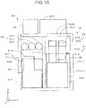
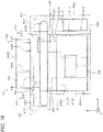
- FIGS. 15 and 16 show a gas supply system 2b according to further another example of the second embodiment.
- a dispenser 11 and a hydrogen receiving unit 28 are also arranged in a housing 4.
- the gas supply system 2b of this modification is configured as one package including the dispenser 11 and the hydrogen receiving unit 28.
- a compressor unit 21 is arranged near one end in the X direction (longitudinal direction of accumulator 231) in the housing 4 similarly to the gas supply system 2 of the second embodiment.
- the housing 4 is provided with cover members 40 on opposite sides in the X direction.
- An installing portion 46 for arranging the dispenser 11 is provided below the cover member 40 closer to the compressor unit 21.
- the housing 4 can be said to include a main body portion 44 between a pair of second side portions 412, the cover members 40 adjacent to upper parts of the second side portions 412 and the installing portion 46 located below one of the cover members 40.
- the installing portion 46 includes a vertical portion 46a extending downward from an outer end part of the cover member 40 and a bottom portion 46b extending in the X direction from a lower end part of the vertical portion 46a toward the second side portion 412.
- the dispenser 11 is located below an accumulator unit 23 and arranged on the bottom portion 46b.
- the hydrogen receiving unit 28 is arranged at a side opposite to the dispenser 11 with respect to the compressor unit 21 in the X direction. More specifically, the hydrogen receiving unit 28 is arranged in proximity to the second side portion 412 distant from the compressor unit 21 in the main body portion 44. Note that the hydrogen receiving unit 28 is located at a position displaced from the dispenser 11 and the accumulator unit 23 in the Y direction as shown in FIG. 15 .
- the hydrogen receiving unit 28 includes unillustrated pressure reducing valves and various instrumentation tools.
- the pressure reducing valve is for reducing the pressure of the hydrogen gas so that the hydrogen gas is received by a compressor 212 through a gas flow path 20 from outside, and arranged on a suction side of the compressor 212 in the gas flow path 20.
- a gas supply system is directed to a gas supply system for supplying gas to filling equipment for filling gas into a tank-mounted apparatus, including a compressor unit including a driver and a compressor configured to compress the gas by being driven by the driver, a accumulator unit including a plurality of accumulators and configured to store the gas discharged from the compressor unit, a pre-cooling system configured to cool the gas flowing into the filling equipment from the accumulator unit and a rectangular parallelepiped housing configured to house at least a part of the pre-cooling system, the compressor unit and the accumulator unit.
- the accumulator unit is located laterally to the compressor unit and the part of the pre-cooling system is located at least either below the accumulator unit or above the compressor unit.
- an installation area of the gas supply system can be reduced.
- a gas supply system is directed to a gas supply system for supplying gas to filling equipment for filling gas into a tank-mounted apparatus, including a compressor unit including a driver and a compressor configured to compress the gas by being driven by the driver, a accumulator unit including a plurality of accumulators and configured to store the gas discharged from the compressor unit, a pre-cooling system configured to cool the gas flowing into the filling equipment from the accumulator unit and a rectangular parallelepiped housing configured to house at least a part of the pre-cooling system, the compressor unit and the accumulator unit.
- the accumulator unit is located above the compressor unit, and the accumulator unit and the compressor unit extend along one side portion of the housing.
- an installation area of the gas supply system can be reduced.
- the accumulator unit may be located above a bottom portion of the housing.
- each of the plurality of accumulators may include a projecting portion projecting from the housing. In this way, it is possible to ensure a sufficient volume of the accumulators while suppressing the installation area of the gas supply system.
- the gas supply system may further include a cover member for covering the projecting portions.
- a cover member for covering the projecting portions.
- an upper surface of the cover member may be flush with that of the housing. In this way, an area of a top portion of the gas supply system can be increased.
- the plurality of accumulators may be arranged in parallel in a horizontal plane. In this way, it is possible to provide many accumulators while suppressing a height of the gas supply system.
- the accumulator unit may further include connecting portions provided for the respective plurality of accumulators.
- the plurality of accumulators may be respectively connectable to other accumulators via the connecting portions. In this way, a storage amount of the gas can be increased.
- the gas supply system may further include a gas cooler fixed to the compressor and configured to exchange heat of the gas discharged from the compressor and heat of cooling fluid.
- the gas cooler may be a laminated body in which a plurality of gas flow paths in which the gas flows and a plurality of cooling flow paths in which the cooling fluid flows are alternately laminated. In this way, the installation area can be further reduced.
- the gas supply system may include a heat exhauster arranged on the top portion of the housing and configured to cool the cooling fluid by the flow of air. In this way, the installation area can be further reduced.
- the pre-cooling system may include a brine circuit configured to cool the gas flowing in the filling equipment using brine and a refrigerator configured to cool the brine
- the refrigerator may include an evaporator configured to cool the brine by evaporating a refrigerant, a refrigerant compressor configured to compress the refrigerant flowing out from the evaporator, a condenser configured to condense the refrigerant compressed by the refrigerant compressor by the flow of air and an expander configured to expand the refrigerant flowing out from the condenser, the evaporator, the refrigerant compressor and the expander may be arranged in the housing and the condenser may be arranged on the top portion of the housing. Since the condenser is structured to condense the refrigerant by air cooling, the condenser can be arranged on the top portion of the housing and the installation area can be further reduced.
- the plurality of accumulators may extend along a side portion of the housing having a surface substantially perpendicular to an arrangement direction in which the compressor unit and the accumulator unit are arranged. In this way, the installation area can be further reduced.
- the top portion of the housing may include an opening and the compressor unit may overlap the opening in a vertical direction. In this way, maintenance for the compressor unit can be easily carried out.
- the number of the plurality of accumulators may be three, one may be used in a low-pressure region of a tank in the tank-mounted apparatus, another one may be used in a medium-pressure region and still another one may be used in a high-pressure region when the filling equipment fills the gas into the tank-mounted apparatus. In this way, the gas can be efficiently supplied to the tank-mounted apparatus.
- the compressor unit and the accumulator unit may be explosion-proof, the pre-cooling system may be non-explosion-proof, and the part of the pre-cooling system in the housing may be arranged in a non-explosion-proof portion.
- a control unit may be further provided which controls the compressor unit, the accumulator unit and the pre-cooling system. In this way, the control unit and the pre-cooling system can be reduced in size and cost can be reduced.
- the gas supply system may include a receiving unit configured to receive the gas to be sucked into the compressor from outside.
- the filling equipment may be arranged at a side opposite to the receiving unit with respect to the compressor unit in a longitudinal direction of the accumulators. In this way, a pipe for connecting the receiving unit and the compressor unit and a pipe for connecting the filling equipment and the compressor can be prevented from becoming longer.
- a hydrogen station includes filling equipment and a gas supply system configured to supply hydrogen gas to the filling equipment, wherein the filling equipment fills the hydrogen gas into a tank-mounted apparatus.
- the filling equipment may be arranged adjacent to a side portion of the housing. In this way, an installation area of the entire system including the gas supply system and the filling equipment can be further reduced.
Landscapes
- Engineering & Computer Science (AREA)
- Mechanical Engineering (AREA)
- General Engineering & Computer Science (AREA)
- Chemical & Material Sciences (AREA)
- Life Sciences & Earth Sciences (AREA)
- Sustainable Energy (AREA)
- Sustainable Development (AREA)
- Combustion & Propulsion (AREA)
- Transportation (AREA)
- Chemical Kinetics & Catalysis (AREA)
- General Chemical & Material Sciences (AREA)
- Oil, Petroleum & Natural Gas (AREA)
- Filling Or Discharging Of Gas Storage Vessels (AREA)
- Motor Or Generator Cooling System (AREA)
Description
- The present invention relates to a gas supply system and a hydrogen station using the gas supply system.
- A hydrogen compressing apparatus used in a hydrogen station is disclosed in
patent literature 1. The hydrogen compressing apparatus is such that a hydrogen compressing apparatus main body, a compressor drive motor, a gas cooler and the like are installed on a common base. Hydrogen gas increased in pressure stepwise to a predetermined pressure in the hydrogen compressing apparatus is temporarily stored in an accumulator unit. To supply the hydrogen gas increased in pressure to a fuel cell vehicle, a dispenser with an adapter compatible with a fueling port of the fuel cell vehicle is connected to the accumulator unit. - A hydrogen station disclosed in
patent literature 2 includes a first support base, a compressor, a first accumulator, a dispenser, a heat exchanger for cooling hydrogen gas supplied to the dispenser and a first expansion unit connection branch line. The compressor, the first accumulator, the heat exchanger and the dispenser are arranged on the first support base. The first expansion unit connection branch line is connected to a second accumulator constituting a first accumulator unit for expansion (accumulator unit for expansion). - A hydrogen station disclosed in
patent literature 3 includes a gas supply system as specified in the preamble ofclaims 1 to 3.Patent literature 4 discloses an alternative gas supply system for low pressure natural gas or other gaseous hydrocarbon fuels.. - In the hydrogen compressing apparatus disclosed in
patent literature 1, a horizontally extending cylinder is provided and an area occupied by a hydrogen compressor is large. Further, the gas cooler having a relatively large size is used. As a result, the hydrogen compressing apparatus is enlarged. Furthermore, since the hydrogen compressing apparatus and the accumulator unit are provided as separate bodies, the entire hydrogen station is enlarged. In the hydrogen station disclosed inpatent literature 2, since the compressor, the first accumulator, the heat exchanger and the dispenser are arranged on the first support base, an installation area of the first support base is large. In the hydrogen station disclosed inpatent literature 3, a refrigerator of a pre-cooling system is housed in a housing and the other devices working with hydrogen gas are arranged outside the housing. The gas supply system disclosed inpatent literature 4 has a gas cooler configured to cool gas flowing from a compressor unit into an accumulator unit or from the compressor unit into a filling equipment. -
- Patent literature 1:
JP 2011 132876 A - Patent literature 2:
JP 2013 57384 A - Patent literature 3:
JP 2013 24287 A - Patent literature 4:
US 4 531 558 A - The present invention aims to reduce an installation area of a gas supply system and a hydrogen station using the gas supply system.
- The present invention is directed to a gas supply system as defined in any one of
independent claims 1 to 3, and a hydrogen station as defined in dependent claim 18. -
-
FIG. 1 is a diagram showing a hydrogen station including a gas supply system according to a first embodiment of the present invention, -
FIG. 2 is a diagram showing a gas cooling unit, -
FIG. 3 is a diagram showing a gas cooler, -
FIG. 4 is a plan view of a first plate, -
FIG. 5 is a plan view of a second plate, -
FIG. 6 is a diagram showing a refrigerator, -
FIG. 7 is a side view of the gas supply system, -
FIG. 8 is a side view of the gas supply system, -
FIG. 9 is a diagram showing a hydrogen station according to another example, -
FIG. 10 is a side view of a gas supply system according to a second embodiment of the present invention, -
FIG. 11 is a side view of the gas supply system according to the second embodiment of the present invention, -
FIG. 12 is a diagram showing a hydrogen station according to another example of the second embodiment of the present invention, -
FIG. 13 is a diagram showing a gas supply system according to another example of the second embodiment of the present invention, -
FIG. 14 is a diagram showing a gas supply system according to another example of the second embodiment, -
FIG. 15 is a side view showing a gas supply system according to another example of the -
FIG. 16 is a side view showing a gas supply system according to another example of the second embodiment. -
FIG. 1 is a diagram showing ahydrogen station 10 according to a first embodiment of the present invention. Thehydrogen station 10 includes agas supply system 2 and adispenser 11 as filling equipment. Thegas supply system 2 supplies hydrogen gas to thedispenser 11. Thedispenser 11 fills the hydrogen gas into a vehicle which is a tank-mounted apparatus. Thevehicle 9 is, for example, a fuel cell vehicle. Thegas supply system 2 includes agas flow path 20, acompressor unit 21, agas cooling unit 22, anaccumulator unit 23, apre-cooling system 24, ahousing 4 shown by chain double-dashed line and acontrol unit 29. Thecompressor unit 21, a part of thegas cooling unit 22 and theaccumulator unit 23 are arranged on thegas flow path 20. The hydrogen gas flows toward thedispenser 11 in thegas flow path 20. Thecontrol unit 29 controls thecompressor unit 21, theaccumulator unit 23 and thepre-cooling system 24. Most of devices of thegas supply system 2 are housed in the housing 4 (described in detail later). - The
compressor unit 21 is a reciprocating compressor and includes adriver 211 andcompressors 212. Thecompressor 212 includes a piston and a cylinder, and gas is compressed in the cylinder by driving the piston by the power of thedriver 211. In this embodiment, there are fivecompressors 212. Thegas cooling unit 22 cools the hydrogen gas discharged from thecompressors 212. -
FIG. 2 is a diagram showing the configuration of thegas cooling unit 22. Thegas cooling unit 22 includes a coolingwater flow path 220 filled with cooling water as cooling fluid, acooling water pump 221,gas coolers 222 and aheat exhauster 223. Thegas cooler 222 is a microchannel heat exchanger. Thegas flow path 20 shown inFIGS. 1 and2 is connected to thegas cooler 222. Theheat exhauster 223 includes a heat exchanger 223a and afan 223b. The coolingwater pump 221, thegas coolers 222 and the heat exchanger 223a of theheat exhauster 223 are arranged in the coolingwater flow path 220. In thegas cooling unit 22, the hydrogen gas discharged from discharging portions of thecompressors 212 and the cooling water exchange heat in thegas coolers 222, whereby the hydrogen gas in thegas flow path 20 is cooled. The cooling water having absorbed heat flows into the heat exchanger 223a of theheat exhauster 223 and is cooled by the flow of air generated by thefan 223b. The cooled cooling water is fed to thegas coolers 222 again by the coolingwater pump 221. -
FIG. 3 is a schematic diagram of thegas cooler 222. InFIG. 3 , inflow portions and outflow portions for the cooling water and hydrogen gas are not shown. Thegas cooler 222 includes a plurality offirst plates 224 and a plurality ofsecond plates 225. Thegas cooler 222 is a laminated body in which thefirst plates 224 and thesecond plates 225 are alternately laminated. Theplates -
FIG. 4 is a plan view of thefirst plate 224. Thefirst plate 224 is formed with a plurality of gas flow paths 224a in which the hydrogen gas flows.FIG. 5 is a plan view of thesecond plate 225. Thesecond plate 225 is formed with a plurality of coolingwater flow paths 225a in which the cooling water flows. The hydrogen gas flowing in the gas flow paths 224a is cooled by the flow of the cooling water in the coolingwater flow paths 225a. - The
accumulator unit 23 shown inFIG. 1 includes fouraccumulators 231 having the same design pressure. The hydrogen gas discharged from thecompressor unit 21 is stored in eachaccumulator 231. - The
pre-cooling system 24 includes arefrigerator 3 and a brine circuit 5. InFIG. 1 , devices of therefrigerator 3 other than anevaporator 31 are shown by one rectangle. The brine circuit 5 includes abrine flow path 240, abrine pump 241 and apre-cooling heat exchanger 242 which is a microchannel heat exchanger. Note that the brine circuit 5 may be provided with an unillustrated brine tank for storing brine. Brine is filled and thebrine pump 241, thepre-cooling heat exchanger 242 and therefrigerator 3 are arranged in thebrine flow path 240. - In the brine circuit 5, the hydrogen gas and the brine exchange heat in the
pre-cooling heat exchanger 242, whereby the hydrogen gas before being filled into thevehicle 9 from thedispenser 11 is cooled. The brine having absorbed heat flows into therefrigerator 3 to be cooled. The cooled brine is fed to thepre-cooling heat exchanger 242 again by thebrine pump 241. -
FIG. 6 is a diagram showing the configuration of therefrigerator 3. Therefrigerator 3 includes arefrigerant flow path 30, theevaporator 31, arefrigerant compressor 32, acondenser 33 and anexpander 34. A refrigerant is filled and theevaporator 31, therefrigerant compressor 32, thecondenser 33 and theexpander 34 are arranged in therefrigerant flow path 30. Theevaporator 31 is connected to thebrine flow path 240 shown inFIGS. 1 and6 . In theevaporator 31, the brine and the refrigerant exchange heat, whereby the brine is cooled and the refrigerant evaporates. Therefrigerant compressor 32 shown inFIG. 6 compresses the refrigerant flowing out from theevaporator 31. Thecondenser 33 includes aheat exchanger 331 through which the refrigerant flows, and afan 332. The refrigerant flowing into theheat exchanger 331 from therefrigerant compressor 32 is dissipated in heat and condensed by the flow of air generated by thefan 332. Theexpander 34 expands the refrigerant flowing out from thecondenser 33 and the expanded refrigerant flows into theevaporator 31. In this way, the brine is cooled by a so-called heat pump cycle in thepre-cooling system 24. - When the hydrogen gas is filled into the
vehicle 9 shown inFIG. 1 , the hydrogen gas fed from an unillustrated gas supply source is compressed by thecompressor unit 21 and stored in theaccumulator unit 23 in advance while being cooled by thegas cooling unit 22. - When the
vehicle 9 is carried into thehydrogen station 10, the hydrogen gas is supplied to thedispenser 11 from theaccumulator unit 23 and thedispenser 11 fills the hydrogen gas into thevehicle 9 in accordance with a predetermined filling protocol. - At this time, in the
accumulator unit 23, the hydrogen gas is first fed from two accumulators 231 (e.g. upper twoaccumulators 231 inFIG. 1 ). In the following description, these two accumulators are denoted by "231a" in the case of being distinguished from the other accumulators. Thedispenser 11 indirectly measures a pressure in thevehicle 9 and sends thegas supply system 2 with an instruction to stop the feed of the hydrogen gas from the accumulators 231a when judging that a pressure difference between in thevehicle 9 and in the accumulators 231a has dropped to or below a predetermined value. - Subsequently, the
gas supply system 2 releases another accumulator 231 (e.g. thethird accumulator 231 from the top inFIG. 1 ). This causes the hydrogen gas to be fed from thisaccumulator 231 to thedispenser 11. Hereinafter, this third accumulator is denoted by "231b" in the case of being distinguished from the other accumulators. In this way, a pressure difference between in the dispenser 11 (or accumulator 231b) and in thevehicle 9 is recovered and a flow rate of the hydrogen gas to be filled into thevehicle 9 is ensured. If a pressure of a tank in thevehicle 9 increases and thedispenser 11 judges that the pressure difference between in the accumulator 231b and in thevehicle 9 has dropped to or below the predetermined value, thegas supply system 2 stops the feed of the hydrogen gas from the accumulator 231b and releases still another accumulator (one located on a lower side inFIG. 1 ). This causes the hydrogen gas to be fed from this other accumulator. In this way, the pressure difference between in thedispenser 11 and in thevehicle 9 is ensured and a sufficient amount of the hydrogen gas is filled. When the pressure of the tank in thevehicle 9 is judged to have reached a set value, the supply of the hydrogen gas from thegas supply system 2 is stopped. - As described above, in the
accumulator unit 23, two accumulators 231a of the fouraccumulators 231 are used in a low-pressure region (e.g. 0 MPa to 40 MPa) of the tank of thevehicle 9, another accumulator 231b is used in a medium-pressure region (40 MPa to 60 MPa) and still another accumulator is used in a high-pressure region (60 MPa to 70 MPa). Thegas supply system 2 switches theaccumulators 231 according to three pressure regions of thevehicle 9, whereby thedispenser 11 can efficiently fill the hydrogen gas in accordance with the filling protocol. Further, by using two accumulators 231a in the low-pressure region where a required flow rate of the hydrogen gas is higher than in the medium- and high-pressure regions, the flow rate of the hydrogen gas is ensured as compared to the case where only one accumulator is used. Thus, the hydrogen gas can be efficiently filled into thevehicle 9 even if the accumulators 231a are small in size. - Next, a positional relationship of each device of the
gas supply system 2 is described. In thegas supply system 2, thecompressor unit 21 and theaccumulator unit 23 are housed in thehousing 4 shown by chain double-dashed line. Further, various devices of thepre-cooling system 24 except thepre-cooling heat exchanger 242 and the condenser 33 (seeFIG. 6 ) of therefrigerator 3 and various devices of thegas cooling unit 22 except theheat exhausting unit 223 shown inFIG. 2 are also housed in thehousing 4. -
FIG. 7 is a side view of thegas supply system 2.FIG. 8 is a view of thegas supply system 2 when viewed from a left side ofFIG. 7 . InFIGS. 7 and8 , thehousing 4 is shown by chain double-dashed line. Further, only main devices of thegas supply system 2 are shown and peripheral members such as pipes are not shown. InFIGS. 7 and8 , thebrine pump 241 of thepre-cooling system 24 and theevaporator 31 of therefrigerator 3 shown inFIG. 1 and therefrigerant compressor 32 and theexpander 34 shown inFIG. 6 are shown by one rectangle denoted by 24. - The
housing 4 has a rectangular parallelepiped shape. Anopening 421 is formed on atop portion 42 of thehousing 4. Theopening 421 is closed by an openable andclosable lid portion 422. In thehousing 4, theaccumulator unit 23 is arranged laterally adjacent to thecompressor unit 21 in a Y direction (i.e. a lateral direction ofFIG. 7 and a direction perpendicular to the plane ofFIG. 8 ). A part of thepre-cooling system 24 is arranged above theaccumulator unit 23. In the following description, the Y direction in which thecompressor unit 21 and theaccumulator unit 23 are arranged is called an "arrangement direction". An X direction is a direction perpendicular to the arrangement direction in a horizontal plane (i.e. a direction perpendicular to the plane ofFIG. 7 and a lateral direction ofFIG. 8 ). A Z direction is perpendicular to the X and Y directions and coincides with a gravity direction. Hereinafter, the Z direction is referred to as a "vertical direction". - The
compressor unit 21 and theaccumulator unit 23 are explosion-proof. Apart 491 of the interior of thehousing 4 where thecompressor unit 21 and theaccumulator unit 23 are arranged is called an "explosion-proof portion 491" below. Note that electric devices and instrumentation attached to thecompressor unit 21 and theaccumulator unit 23 are also explosion-proof in the explosion-proof portion 491. On the other hand, thepre-cooling system 24 is not explosion-proof. Apart 492 of the interior of thehousing 4 where thepre-cooling system 24 is arranged is called a "non-explosion-proof portion 492". As shown inFIG. 8 , thecontrol unit 29 is arranged in the non-explosion-proof portion 492. In the non-explosion-proof portion 492, electric devices and instrumentation attached to thepre-cooling system 24 and thecontrol unit 29 are also not explosion-proof. Unillustrated gas detection sensors are arranged in the explosion-proof portion 491 and the non-explosion-proof portion 492 shown inFIGS. 7 and8 to control the leakage of the hydrogen gas in thehousing 4. - The
compressor unit 21 is of a so-called vertical installation type and thecompressors 212 are arranged in thehousing 4 while being located above thedriver 211 in the vertical direction. Specifically, the pistons vertically reciprocate in the cylinders in thecompressors 212. In the vertical direction, theentire compressors 212 overlap theopening 421. This enables the parts such as thecompressors 212 to be easily taken out to the outside of thehousing 4 through theopening 421 by opening thelid portion 422 when maintenance is carried out for thecompressor unit 21. Note that theheat exhauster 223 and thecondenser 33 are spaced from theopening 421. In thegas supply system 2, thecompressors 212 may partly overlap theopening 421 in the vertical direction or theentire compressors 212 may overlap theopening 421 if a desired part of thecompressor unit 21 can be taken out. - In the
accumulator unit 23, two of the fouraccumulators 231 are arranged in the arrangement direction and the remaining twoaccumulators 231 vertically overlap the above twoaccumulators 231. Eachaccumulator 231 extends alongside portions 411 having surfaces substantially perpendicular to the arrangement direction, i.e. surface whose normals are parallel to the arrangement direction out of fourside portions housing 4 perpendicularly standing up with respect to an installation surface. Theside portions 411 are referred to as "first side portions 411" below. Further, twoside portions 412 having surfaces parallel to the arrangement direction, i.e. surfaces perpendicular to an extending direction of theaccumulators 231 are referred to as "second side portions 412". - The
gas coolers 222 of thegas cooling unit 22 are fixed to thecompressors 212 of thecompressor unit 21 in the explosion-proof portion 491. Further, the cooling water pump 221 (seeFIG. 2 ) is also arranged in the explosion-proof portion 491. Thegas coolers 222 and the coolingwater pump 221 are explosion-proof. Theheat exhauster 223 is arranged on thetop portion 42 of thehousing 4. - In the
pre-cooling system 24, thebrine pump 241 and theevaporator 31 of therefrigerator 3 shown inFIG. 1 and therefrigerant compressor 32 and theexpander 34 shown inFIG. 6 are arranged in the non-explosion-proof portion 492. Thecondenser 33 is arranged on thetop portion 42 of thehousing 4. Note that thepre-cooling heat exchanger 242 is arranged near thedispenser 11 ofFIG. 1 . Thepre-cooling heat exchanger 242 may be arranged in thedispenser 11. Since the air-cooledheat exhauster 223 andcondenser 33 are utilized in thegas supply system 2, a degree of freedom in installation position is improved as compared to water-cooled ones and thetop portion 42 of thehousing 4 can be effectively utilized. - As described above, the
compressor unit 21, thegas cooling unit 22, theaccumulator unit 23 and each device of thepre-cooling system 24 except thepre-cooling heat exchanger 242 are provided in thehousing 4 or on thetop portion 42 of thehousing 4. Thus, thegas supply system 2 can be small in size. - The
hydrogen station 10 including thegas supply system 2 according to the first embodiment of the present invention has been described above. In thegas supply system 2, thecompressor unit 21 is vertically arranged in thehousing 4 and thepre-cooling system 24 is arranged above theaccumulator unit 23. As compared to a gas supply system of a so-called horizontal installation type in which a compressor unit is arranged in a horizontal plane, an area occupied by thecompressor unit 21 can be reduced. By covering thecompressor unit 21 and theaccumulator unit 23 by onerectangular parallelepiped housing 4, a space (non-explosion-proof portion 492 in this embodiment) is formed above theaccumulator unit 23. Thus, at least a part of thepre-cooling system 24 can be arranged in this space. In this way, the installation area of thegas supply system 2 can be reduced and thehydrogen station 10 can be reduced in size. - Particularly, since the
pre-cooling heat exchanger 242 is a microchannel heat exchanger, it is possible to reduce thepre-cooling heat exchanger 242 in size while ensuring hydrogen gas cooling efficiency. As a result, the other devices of thepre-cooling system 24 can also be reduced in size. In this way, many devices of thepre-cooling system 24 can be arranged in thehousing 4 and the installation area of thegas supply system 2 can be reduced. - Further, since the
gas coolers 222 are also small-size microchannel heat exchangers, the installation area of thegas supply system 2 can be further reduced by directly fixing thegas coolers 222 to thecompressors 212 of thecompressor unit 21. Since theheat exhauster 223 of thegas cooling unit 22 and thecondenser 33 of therefrigerator 3 are arranged on thetop portion 42 of thehousing 4, the installation area of thegas supply system 2 can be further reduced as compared to the case where these members are arranged not in or on thehousing 4. - In the
accumulator unit 23, two of the fouraccumulators 231 are arranged in each of upper and lower stages. A width of theaccumulator unit 23 in the arrangement direction can be suppressed as compared to the case where the fouraccumulators 231 are laterally arranged in parallel, and a vertical height can be suppressed as compared to the case where the fouraccumulators 231 are vertically arranged one above another. As just described, in thegas supply system 2, it is possible to ensure the number of theaccumulators 231 while suppressing the size of theaccumulators 231. Further, since a longitudinal direction of theaccumulators 231 extends along thefirst side portions 411 of thehousing 4, a width of thehousing 4 in the arrangement direction can be prevented from becoming unnecessarily large and the installation area of thegas supply system 2 can be further reduced. - The non-explosion-
proof portion 492 is formed in thehousing 4. This can eliminate the need for making thepre-cooling system 24 and thecontrol unit 29 explosion-proof and can prevent the enlargement of these devices and drastically suppress cost. -
FIG. 9 is a diagram showing a part of ahydrogen station 10a according to another example of the first embodiment. Thedispenser 11 is attached to one of thesecond side portions 412 having the surface parallel to the arrangement direction of thehousing 4. Thepre-cooling heat exchanger 242 of thepre-cooling system 24 is arranged in thedispenser 11. In a structure shown inFIG. 9 , thedispenser 11 is attached to thegas supply system 2, whereby theentire hydrogen station 10a can be reduced in size. In thehydrogen station 10a, thedispenser 11 may be slightly spaced from thesecond side portion 412 as long as it is arranged adjacent to thesecond side portion 412. - Although the first embodiment of the present invention has been described above, the present invention is not limited to the above first embodiment and various changes are possible.
- In the
hydrogen station 10a shown inFIG. 9 , a cover for covering theheat exhauster 223 and thecondenser 33 may be mounted on thetop portion 42 of thehousing 4. - The
gas coolers 222 may be plate heat exchangers other than microchannel heat exchangers if they are directly fixed to thecompressors 212. In theaccumulator unit 23, the number of theaccumulators 231 needs not necessarily be four. The number of theaccumulators 231 may be three if a high flow rate of the hydrogen gas is not required in the low-pressure region of the tank of thevehicle 9. Further, the number of theaccumulators 231 may be five or more if a sufficient arrangement space is ensured in the explosion-proof portion 491. In the case of usingshort accumulators 231, one accumulator group may be formed by a plurality ofaccumulators 231 and a plurality of accumulator groups may be arranged in the longitudinal direction of theaccumulators 231, i.e. in a direction perpendicular to the arrangement direction in a horizontal plane. - Cooling fluid other than water may be used in the
gas cooling unit 22. The coolingwater pump 221 may be arranged on thetop portion 42 of thehousing 4. In thehydrogen station 10a, thedispenser 11 may be arranged adjacent to thefirst side portion 411. - The
gas supply system 2 may be utilized to fill the hydrogen gas into tank-mounted apparatuses other than vehicles. Thegas supply system 2 may be used to supply gas other than hydrogen gas. - Here, the above first embodiment is summarized.
- The first embodiment is directed to a gas supply system for supplying gas to filling equipment for filling gas into a tank-mounted apparatus, including a compressor unit including a driver and a compressor configured to compress the gas by being driven by the driver, an accumulator unit including a plurality of accumulators and configured to store the gas discharged from the compressor unit, a pre-cooling system configured to cool the gas flowing into the filling equipment from the accumulator unit and a rectangular parallelepiped housing configured to house at least a part of the pre-cooling system, the compressor unit and the accumulator unit, wherein the compressor unit is arranged with the compressor located above the driver and the part of the pre-cooling system is arranged above the accumulator unit on a side of the compressor unit in the housing.
- In this gas supply system, an installation area can be reduced.
- The plurality of accumulators of the gas supply system may extend along a side portion of the housing having a surface substantially perpendicular to an arrangement direction in which the compressor unit and the accumulator unit are arranged. In this mode, the installation area can be further reduced.
- The gas supply system may further include a gas cooler fixed to the compressor and configured to exchange heat of the gas discharged from the compressor and heat of cooling fluid. In this case, the gas cooler may be a laminated body in which a plurality of gas flow paths in which the gas flows and a plurality of cooling flow paths in which the cooling fluid flows are alternately laminated. In this mode, the installation area can be further reduced.
- The gas supply system may be provided with a heat exhauster arranged on a top portion of the housing and configured to cool the cooling fluid by the flow of air. In this mode, the installation area can be further reduced.
- In the gas supply system, the pre-cooling system may include a brine circuit configured to cool the gas flowing in the filling equipment using brine and a refrigerator configured to cool the brine. Further, the refrigerator may include an evaporator configured to cool the brine by evaporating a refrigerant, a refrigerant compressor configured to compress the refrigerant flowing out from the evaporator, a condenser configured to condense the refrigerant compressed by the refrigerant compressor by a flow of air and an expander configured to expand the refrigerant flowing out from the condenser. Further, the evaporator, the refrigerant compressor and the expander may be arranged in the housing and the condenser may be arranged on the top portion of the housing. Since the condenser is structured to condense the refrigerant by air cooling in this mode, the condenser can be arranged on the top portion of the housing and the installation area can be further reduced.
- The top portion of the housing of the gas supply system may include an opening. In this case, the compressor unit may overlap the opening in a vertical direction. In this mode, maintenance for the compressor unit can be easily carried out.
- The accumulator unit of the gas supply system may be formed of four accumulators, two each of which are arranged in each of upper and lower stages. In this mode, it is possible to ensure the number of the accumulators while suppressing the size of the accumulator unit.
- In the gas supply system, two out of the four accumulators may be used in a low-pressure region of a tank in the tank-mounted apparatus, another one may be used in a medium-pressure region and still another one may be used in a high-pressure region when the filling equipment fills the gas into the tank-mounted apparatus. In this mode, the gas can be efficiently supplied to the tank-mounted apparatus.
- In the gas supply system, the compressor unit and the accumulator unit may be explosion-proof, the pre-cooling system may be non-explosion-proof, and the part of the pre-cooling system in the housing may be arranged in a non-explosion-proof portion. Further, a control unit may be further provided which controls the compressor unit, the accumulator unit and the pre-cooling system. In this mode, the control unit and the pre-cooling system can be reduced in size and cost can be reduced.
- The first embodiment is directed to a hydrogen station with filling equipment and a gas supply system configured to supply hydrogen gas to the filling equipment, wherein the filling equipment fills the hydrogen gas into a tank-mounted apparatus.
- In the hydrogen station, the filling equipment may be arranged adjacent to a side portion of the housing. In this mode, an installation area of the entire system including the gas supply system and the filling equipment can be reduced.
- A
gas supply system 2 according to a second embodiment of the present invention is described. Here, only configurations different from the first embodiment are described and the same configurations as the first embodiment are not described. Note thatFIGS. 1 to 6 are also used as views and diagrams showing the supply system according to the second embodiment. -
FIG. 10 is a side view of thegas supply system 2.FIG. 11 is a view of thegas supply system 2 when viewed from a left side ofFIG. 10 . InFIGS. 10 and11 , ahousing 4 is shown by chain double-dashed line. Further, only main devices of thegas supply system 2 are shown and peripheral members such as pipes are not shown. InFIGS. 10 and11 , abrine pump 241 of apre-cooling system 24 and anevaporator 31 of arefrigerator 3 shown inFIG. 1 and arefrigerant compressor 32 and anexpander 34 shown inFIG. 6 are shown by one rectangle denoted by 24. - The
housing 4 has a rectangular parallelepiped shape. Anopening 421 is formed on atop portion 42 of thehousing 4 and closed by an openable andclosable lid portion 422. In thehousing 4, anaccumulator unit 23 and a part of thepre-cooling system 24 is arranged laterally adjacent to acompressor unit 21 in a Y direction (i.e. a lateral direction ofFIG. 10 and a direction perpendicular to the plane ofFIG. 11 ). Theaccumulator unit 23 is located above a bottom part of thehousing 4 and thepre-cooling system 24 is located below theaccumulator unit 23. - In the
accumulator unit 23, threeaccumulators 231 are arranged in parallel in an arrangement direction in a horizontal plane. Eachaccumulator 231 extends alongside portions 411 having surfaces substantially perpendicular to the arrangement direction, i.e. surface whose normals are parallel to the arrangement direction out of fourside portions housing 4 perpendicularly standing up with respect to an installation surface. Theside portions 411 are referred to as "first side portions 411" below. Further, twoside portions 412 having surfaces parallel to the arrangement direction, i.e. surfaces perpendicular to an extending direction of theaccumulators 231 are referred to as "second side portions 412". - As shown in
FIG. 11 , eachaccumulator 231 includes two projectingportions 232 projecting from the twosecond side portions 412 of thehousing 4.Cover members 40 for respectively covering the projectingportions 232 are mounted on the twoside portions 412 of thehousing 4. Note that thecover members 40 may be regarded as parts of thehousing 4.Upper surfaces 401 of thecover members 40 are flush with anupper surface 420 of thehousing 4. On thehousing 4, unillustrated operation door(s) is/are disposed below one or both of thecover members 40. By opening the operation door(s), maintenance is carried out for thepre-cooling system 24 and thecompressor unit 21. - As shown in
FIGS. 10 and11 ,gas coolers 222 of agas cooling unit 22 are fixed tocompressors 212 of thecompressor unit 21 in an explosion-proof portion 491. Further, a cooling water pump 221 (seeFIG. 2 ) is also arranged in the explosion-proof portion 491 although not shown inFIGS. 10 and11 . Thegas coolers 222 and the coolingwater pump 221 are explosion-proof. Aheat exhauster 223 is arranged on thetop portion 42 of thehousing 4. Since the air-cooledheat exhauster 223 is utilized in thegas supply system 2, a degree of freedom in installation position is improved as compared to the water-cooled one and thetop portion 42 of thehousing 4 can be effectively utilized. - In the
pre-cooling system 24, thebrine pump 241 and theevaporator 31 of therefrigerator 3 shown inFIG. 1 and therefrigerant compressor 32 and theexpander 34 shown inFIG. 6 are arranged in a non-explosion-proof portion 492 shown inFIGS. 10 and11 . These devices are located below theaccumulator unit 23. If a brine circuit 5 is provided with a brine tank, the brine tank may be arranged below theaccumulator unit 23 in thehousing 4. Acondenser 33 is arranged on thetop portion 42 of thehousing 4. Since thecondenser 33 is also air-cooled similarly to theheat exhauster 223 of thegas cooling unit 22, a degree of freedom in installation position is improved and thetop portion 42 of thehousing 4 can be effectively utilized. Apre-cooling heat exchanger 242 of the brine circuit 5 shown inFIG. 1 is arranged near adispenser 11 outside thehousing 4. Note that thepre-cooling heat exchanger 242 can also be arranged in thedispenser 11. - As described above, the
compressor unit 21, thegas cooling unit 22, theaccumulator unit 23 and each device of thepre-cooling system 24 except thepre-cooling heat exchanger 242 are provided in thehousing 4 or on thetop portion 42 of thehousing 4. - The
hydrogen station 10 including thegas supply system 2 according to the second embodiment of the present invention has been described above. In thegas supply system 2, thecompressor unit 21, theaccumulator unit 23 and the pre-cooling system 24 (however, except thepre-cooling heat exchanger 242 and the condenser 33) as main devices are arranged in thehousing 4, and thepre-cooling system 24 is arranged below theaccumulator unit 23 in the housing. In this way, the installation area of thegas supply system 2 can be reduced and thehydrogen station 10 can be reduced in size. Further, by vertically arranging thecompressor unit 21 in thehousing 4, the installation area can be further reduced. - In the
accumulator unit 23, the threeaccumulators 231 are arranged in parallel in the arrangement direction, whereby it is possible to install theaccumulators 231 while suppressing a height of thegas supply system 2. Since a longitudinal direction of theaccumulators 231 extends along thefirst side portions 411 of thehousing 4, a width of thehousing 4 in the arrangement direction can be prevented from becoming unnecessarily large and the installation area of thegas supply system 2 can be further reduced. Further, by arranging theaccumulators 231 in parallel in the horizontal direction, water can be efficiently sprayed to all theaccumulators 231 when theaccumulators 231 increase in temperature. - In the
gas supply system 2, theaccumulators 231 include the projectingportions 232, whereby a sufficient volume of theaccumulators 231 can be ensured without enlarging the installation area of thegas supply system 2. - Since the
upper surfaces 401 of thecover members 40 are flush with theupper surface 420 of thehousing 4, an area of thetop portion 42 of thehousing 4 can be increased to increase an installation area for thecondenser 33 and theheat exhauster 223 and widen an operation space. - In the
gas supply system 2, since thepre-cooling system 24 having a higher maintenance frequency than theaccumulator unit 23 is arranged in a lower part of thegas supply system 2, a workload of an operator is reduced. - Since the
pre-cooling system 24 and thecontrol unit 29 are provided in the non-explosion-proof portion 492 in thehousing 4, the enlargement of thegas supply system 2 caused by making these devices explosion-proof is prevented and cost is drastically reduced. -
FIG. 12 is a diagram showing a part of ahydrogen station 10a according to another example of the second embodiment. Thedispenser 11 is mounted on one of thesecond side portions 412 having the surface parallel to the arrangement direction of thehousing 4. Thepre-cooling heat exchanger 242 of thepre-cooling system 24 is arranged in thedispenser 11. In a structure shown inFIG. 12 , thedispenser 11 is attached to thegas supply system 2, whereby theentire hydrogen station 10a can be reduced in size. In thehydrogen station 10a, thedispenser 11 may be slightly spaced from thesecond side portion 412 as long as it is arranged adjacent to thesecond side portion 412. -
FIG. 13 is a diagram showing still another example of thegas supply system 2 according to the second embodiment. Theaccumulator unit 23 includes connectingportions 233 attached to rear parts (i.e. end parts opposite to discharging portions for the hydrogen gas) of theaccumulators 231. The connectingportion 233 includes a take-out pipe 233a and aclosing valve 233b and is arranged in thehousing 4. Theaccumulator 231 is connectable in series to anotheraccumulator 81 for extension via the connectingportion 233. Theaccumulator 81 is referred to as an "extension accumulator 81" below. The connectingportions 233 are provided in thecover member 40 shown inFIG. 11 . The extension accumulators 81 are preferably arranged below thecover member 40. In this way, a distance between theaccumulators 231 and theextension accumulators 81 can be shortened. When theextension accumulators 81 are connected to thegas supply system 2 as shown inFIG. 13 , hydrogen gas in theextension accumulator 81 is fed to thecorresponding accumulator 231 if the amount of the hydrogen gas in theaccumulator 231 decreases. - In the
gas supply system 2, theaccumulators 81 can be easily added by providing the connectingportions 233 and a storage amount of the hydrogen gas in thehydrogen system 10 can be increased. As a result, the hydrogen gas can be quickly supplied tomany vehicles 9. By connecting theextension accumulators 81 in series to theaccumulators 231, it is prevented that a flow rate control of the hydrogen gas becomes complicated as compared to the case where theextension accumulators 81 are connected at intermediate positions of flow paths between theaccumulators 231 and the dispenser 11 (seeFIG. 1 ). -
FIG. 14 is a diagram showing a gas supply system 2a according to further another example of the second embodiment. In the gas supply system 2a, anaccumulator unit 23 is located above a compressor unit 21a and apre-cooling system 24 is located laterally to the compressor unit 21a in the Y direction. The compressor unit 21a is of a so-called horizontal installation type and compressors are arranged more backward with respect to the plane ofFIG. 14 than adriver 211. The other structure of the gas supply system 2a is similar to that of thegas supply system 2 according to the second embodiment and similar components are described while being denoted by the same reference signs. - The
accumulator unit 23 and the compressor unit 21a are arranged along afirst side portion 411 of thehousing 4 on a right side ofFIG. 14 . More precisely, a longitudinal direction ofaccumulators 231 of theaccumulator unit 23 and a direction from adriver 211 of the compressor unit 21a toward the compressors are substantially parallel to a surface of thefirst side portion 411. - In the gas supply system 2a, the
accumulator unit 23 is located above the compressor unit 21a, whereby an installation space of the gas supply system 2a can be reduced and ahydrogen system 10 can be reduced in size. By utilizing the compressor unit 21a having a short vertical height, an increase in the height of ahousing 4 is prevented. Note that a diaphragm type compressor unit may be utilized as the compressor unit. The diaphragm type compressor unit may be vertically installed since a vertical height is suppressed as compared to piston type compressor units. - Although the second embodiment and its modifications have been described above, various changes are possible for the above second embodiment.
- In the
hydrogen station 10a shown inFIG. 12 , a cover for covering theheat exhauster 223 and thecondenser 33 may be mounted on thetop portion 42 of thehousing 4. The same holds also for the gas supply system 2a ofFIG. 14 . - In the above second embodiment, a piston type compressor unit of a horizontal installation type may be utilized or a diaphragm type compressor unit may be utilized. In this case, since a space is secured above the
compressor unit 21, theevaporator 31, therefrigerant compressor 32 and theexpander 34 of therefrigerator 3 may be arranged in this space. By arranging thecompressor unit 21 for which maintenance is carried out with a higher frequency than therefrigerator 3 below therefrigerator 3, a workload in carrying out maintenance can be reduced. Further, in the case of providing the brine circuit 5 with a brine tank, the brine tank may be arranged below theaccumulator unit 23. As just described, in thegas supply system 2, various devices of the pre-cooling system arranged in thehousing 4 may be arranged either or both below theaccumulator unit 23 or/and above thecompressor unit 21. - In the above embodiment, the
gas coolers 222 may be plate heat exchangers other than microchannel heat exchangers if they are directly fixed to thecompressors 212. In theaccumulator unit 23, the number of theaccumulators 231 may be other than three. In thegas cooling unit 22, cooling fluid other than water may be used to cool the hydrogen gas. The coolingwater pump 221 may be arranged on thetop portion 42 of thehousing 4. Thegas supply systems 2, 2a may be utilized to fill the hydrogen gas into tank-mounted apparatuses other than vehicles. Thegas supply systems 2, 2a may be used to supply gas other than hydrogen gas. -
FIGS. 15 and16 show agas supply system 2b according to further another example of the second embodiment. In thisgas supply system 2b, adispenser 11 and ahydrogen receiving unit 28 are also arranged in ahousing 4. Thus, thegas supply system 2b of this modification is configured as one package including thedispenser 11 and thehydrogen receiving unit 28. - In the
gas supply system 2b according to the other example of the second embodiment, acompressor unit 21 is arranged near one end in the X direction (longitudinal direction of accumulator 231) in thehousing 4 similarly to thegas supply system 2 of the second embodiment. Thehousing 4 is provided withcover members 40 on opposite sides in the X direction. An installingportion 46 for arranging thedispenser 11 is provided below thecover member 40 closer to thecompressor unit 21. In other words, thehousing 4 can be said to include amain body portion 44 between a pair ofsecond side portions 412, thecover members 40 adjacent to upper parts of thesecond side portions 412 and the installingportion 46 located below one of thecover members 40. The installingportion 46 includes avertical portion 46a extending downward from an outer end part of thecover member 40 and abottom portion 46b extending in the X direction from a lower end part of thevertical portion 46a toward thesecond side portion 412. Thedispenser 11 is located below anaccumulator unit 23 and arranged on thebottom portion 46b. - On the other hand, as shown in
FIG. 16 , thehydrogen receiving unit 28 is arranged at a side opposite to thedispenser 11 with respect to thecompressor unit 21 in the X direction. More specifically, thehydrogen receiving unit 28 is arranged in proximity to thesecond side portion 412 distant from thecompressor unit 21 in themain body portion 44. Note that thehydrogen receiving unit 28 is located at a position displaced from thedispenser 11 and theaccumulator unit 23 in the Y direction as shown inFIG. 15 . - The
hydrogen receiving unit 28 includes unillustrated pressure reducing valves and various instrumentation tools. The pressure reducing valve is for reducing the pressure of the hydrogen gas so that the hydrogen gas is received by acompressor 212 through agas flow path 20 from outside, and arranged on a suction side of thecompressor 212 in thegas flow path 20. - In this configuration, pipes for connecting the
hydrogen receiving unit 28 and thecompressor unit 21 and pipes for connecting thedispenser 11 and thecompressor unit 21 can be prevented from becoming long. - Here, the second embodiment is summarized.
- A gas supply system according to the second embodiment is directed to a gas supply system for supplying gas to filling equipment for filling gas into a tank-mounted apparatus, including a compressor unit including a driver and a compressor configured to compress the gas by being driven by the driver, a accumulator unit including a plurality of accumulators and configured to store the gas discharged from the compressor unit, a pre-cooling system configured to cool the gas flowing into the filling equipment from the accumulator unit and a rectangular parallelepiped housing configured to house at least a part of the pre-cooling system, the compressor unit and the accumulator unit. The accumulator unit is located laterally to the compressor unit and the part of the pre-cooling system is located at least either below the accumulator unit or above the compressor unit.
- According to this gas supply system, an installation area of the gas supply system can be reduced.
- A gas supply system according to the second embodiment is directed to a gas supply system for supplying gas to filling equipment for filling gas into a tank-mounted apparatus, including a compressor unit including a driver and a compressor configured to compress the gas by being driven by the driver, a accumulator unit including a plurality of accumulators and configured to store the gas discharged from the compressor unit, a pre-cooling system configured to cool the gas flowing into the filling equipment from the accumulator unit and a rectangular parallelepiped housing configured to house at least a part of the pre-cooling system, the compressor unit and the accumulator unit. The accumulator unit is located above the compressor unit, and the accumulator unit and the compressor unit extend along one side portion of the housing.
- According to this gas supply system, an installation area of the gas supply system can be reduced.
- In the gas supply system, the accumulator unit may be located above a bottom portion of the housing. In this case, each of the plurality of accumulators may include a projecting portion projecting from the housing. In this way, it is possible to ensure a sufficient volume of the accumulators while suppressing the installation area of the gas supply system.
- The gas supply system may further include a cover member for covering the projecting portions. In this case, an upper surface of the cover member may be flush with that of the housing. In this way, an area of a top portion of the gas supply system can be increased.
- In the gas supply system, the plurality of accumulators may be arranged in parallel in a horizontal plane. In this way, it is possible to provide many accumulators while suppressing a height of the gas supply system.
- In the gas supply system, the accumulator unit may further include connecting portions provided for the respective plurality of accumulators. In this case, the plurality of accumulators may be respectively connectable to other accumulators via the connecting portions. In this way, a storage amount of the gas can be increased.
- The gas supply system may further include a gas cooler fixed to the compressor and configured to exchange heat of the gas discharged from the compressor and heat of cooling fluid. In this case, the gas cooler may be a laminated body in which a plurality of gas flow paths in which the gas flows and a plurality of cooling flow paths in which the cooling fluid flows are alternately laminated. In this way, the installation area can be further reduced.
- The gas supply system may include a heat exhauster arranged on the top portion of the housing and configured to cool the cooling fluid by the flow of air. In this way, the installation area can be further reduced.
- In the gas supply system, the pre-cooling system may include a brine circuit configured to cool the gas flowing in the filling equipment using brine and a refrigerator configured to cool the brine, the refrigerator may include an evaporator configured to cool the brine by evaporating a refrigerant, a refrigerant compressor configured to compress the refrigerant flowing out from the evaporator, a condenser configured to condense the refrigerant compressed by the refrigerant compressor by the flow of air and an expander configured to expand the refrigerant flowing out from the condenser, the evaporator, the refrigerant compressor and the expander may be arranged in the housing and the condenser may be arranged on the top portion of the housing. Since the condenser is structured to condense the refrigerant by air cooling, the condenser can be arranged on the top portion of the housing and the installation area can be further reduced.
- In the gas supply system, the plurality of accumulators may extend along a side portion of the housing having a surface substantially perpendicular to an arrangement direction in which the compressor unit and the accumulator unit are arranged. In this way, the installation area can be further reduced.
- In the gas supply system, the top portion of the housing may include an opening and the compressor unit may overlap the opening in a vertical direction. In this way, maintenance for the compressor unit can be easily carried out.
- In the gas supply system, the number of the plurality of accumulators may be three, one may be used in a low-pressure region of a tank in the tank-mounted apparatus, another one may be used in a medium-pressure region and still another one may be used in a high-pressure region when the filling equipment fills the gas into the tank-mounted apparatus. In this way, the gas can be efficiently supplied to the tank-mounted apparatus.
- In the gas supply system, the compressor unit and the accumulator unit may be explosion-proof, the pre-cooling system may be non-explosion-proof, and the part of the pre-cooling system in the housing may be arranged in a non-explosion-proof portion. Further, a control unit may be further provided which controls the compressor unit, the accumulator unit and the pre-cooling system. In this way, the control unit and the pre-cooling system can be reduced in size and cost can be reduced.
- The gas supply system may include a receiving unit configured to receive the gas to be sucked into the compressor from outside. In this case, the filling equipment may be arranged at a side opposite to the receiving unit with respect to the compressor unit in a longitudinal direction of the accumulators. In this way, a pipe for connecting the receiving unit and the compressor unit and a pipe for connecting the filling equipment and the compressor can be prevented from becoming longer.
- A hydrogen station according to the second embodiment includes filling equipment and a gas supply system configured to supply hydrogen gas to the filling equipment, wherein the filling equipment fills the hydrogen gas into a tank-mounted apparatus.
- In the hydrogen station, the filling equipment may be arranged adjacent to a side portion of the housing. In this way, an installation area of the entire system including the gas supply system and the filling equipment can be further reduced.
Claims (19)
- A gas supply system (2) for supplying gas to filling equipment (11) for filling gas into a tank-mounted apparatus (9), comprising:a compressor unit (21) including a driver (211) and a compressor (212) configured to compress the gas by being driven by the driver (211);an accumulator unit (23) including a plurality of accumulators (231) and configured to store the gas discharged from the compressor unit (21);a pre-cooling system (24) including a refrigerator (3) and a pre-cooling heat exchanger (242) configured to cool the gas flowing into the filling equipment (11) from the accumulator unit (23); anda rectangular parallelepiped housing (4) configured to house a part of the pre-cooling system (24), the part of the pre-cooling system (24) including at least a part of the refrigerator (3) and excluding the pre-cooling heat exchanger (242),characterized in thatthe housing (4) is configured to house, in addition to the part of the pre-cooling system (24), the compressor unit (212) and the accumulator unit (23), andthe compressor unit (21) is arranged with the compressor (212) located above the driver (211), and the part of the pre-cooling system (24) is arranged above the accumulator unit (23) on a side of the compressor unit (21) in the housing (4).
- A gas supply system (2; 2b) for supplying gas to filling equipment (11) for filling gas into a tank-mounted apparatus (9), comprising:a compressor unit (21) including a driver (211) and a compressor (212) configured to compress the gas by being driven by the driver (211);an accumulator unit (23) including a plurality of accumulators (231) and configured to store the gas discharged from the compressor unit (21);a pre-cooling system (24) including a refrigerator (3) and a pre-cooling heat exchanger (242) configured to cool the gas flowing into the filling equipment (11) from the accumulator unit (23); anda rectangular parallelepiped housing (4) configured to house a part of the pre-cooling system (24), the part of the pre-cooling system (24) including at least a part of the refrigerator (3) and excluding the pre-cooling heat exchanger (242),characterized in thatthe housing (4) is configured to house, in addition to the part of the pre-cooling system (24), the compressor unit (212) and the accumulator unit (23), andthe accumulator unit (23) is located laterally to the compressor unit (21), and the part of the pre-cooling system (24) is located at least either below the accumulator unit (23) or above the compressor unit (21).
- A gas supply system (2a) for supplying gas to filling equipment (11) for filling gas into a tank-mounted apparatus (9), comprising:a compressor unit (21a) including a driver (211) and a compressor configured to compress the gas by being driven by the driver (211);an accumulator unit (23) including a plurality of accumulators (231) and configured to store the gas discharged from the compressor unit (21a);a pre-cooling system (24) including a refrigerator (3) and a pre-cooling heat exchanger (242) configured to cool the gas flowing into the filling equipment (11) from the accumulator unit (23); anda rectangular parallelepiped housing (4) configured to house a part of the pre-cooling system (24), the part of the pre-cooling system (24) including at least a part of the refrigerator (3) and excluding the pre-cooling heat exchanger (242),characterized in thatthe housing (4) is configured to house, in addition to the part of the pre-cooling system (24), the compressor unit (21a) and the accumulator unit (23), andthe accumulator unit (23) is located above the compressor unit (21a), and the accumulator unit (23) and the compressor unit (21a) extend along one side portion (411) of the housing (4).
- A gas supply system (2; 2a; 2b) according to any one of claims 1 to 3, wherein:
the plurality of accumulators (231) extend along a side portion (411) of the housing (4) having a surface substantially perpendicular to an arrangement direction in which the compressor unit (21) and the accumulator unit (23) are arranged. - A gas supply system (2; 2b) according to any one of claims 1 to 3, further comprising a gas cooler (222) fixed to the compressor (212) and configured to exchange heat of the gas discharged from the compressor (212) and heat of cooling fluid, wherein:
the gas cooler (222) is a laminated body in which a plurality of gas flow paths in which the gas flows and a plurality of cooling flow paths in which the cooling fluid flows are alternately laminated. - A gas supply system (2; 2b) according to claim 5, comprising a heat exhauster (223) arranged on a top portion (42) of the housing (4) and configured to cool the cooling fluid by the flow of air.
- A gas supply system (2) according to any one of claims 1 to 3, wherein:the pre-cooling system (24) includes:a brine circuit (5) including the pre-cooling heat exchanger (242) and configured to cool the gas flowing in the filling equipment (11) using brine, andthe refrigerator (3);the refrigerator (3) is configured to cool the brine and includes:an evaporator (31) configured to cool the brine by evaporating a refrigerant,a refrigerant compressor (32) configured to compress the refrigerant flowing out from the evaporator (31),a condenser (33) configured to condense the refrigerant compressed by the refrigerant compressor (32) by the flow of air, andan expander (34) configured to expand the refrigerant flowing out from the condenser (33); andthe evaporator (31), the refrigerant compressor (32) and the expander (34) are arranged in the housing (4) and the condenser (33) is arranged on a top portion (42) of the housing (4).
- A gas supply system (2; 2b) according to any one of claims 1 to 3, wherein:a top portion (42) of the housing (4) includes an opening (421); andthe compressor unit (21) overlaps the opening (421) in a vertical direction.
- A gas supply system (2) according to claim 1, wherein:
the accumulator unit (23) is formed of four accumulators (231), two each of which are arranged in each of upper and lower stages. - A gas supply system according to claim 9, wherein:
two out of the four accumulators (231) are used in a low-pressure region of a tank in the tank-mounted apparatus (9), another one is used in a medium-pressure region and still another one is used in a high-pressure region when the filling equipment (11) fills the gas into the tank-mounted apparatus (9). - A gas supply system (2; 2b) according to any one of claims 1 to 3, wherein:the compressor unit (21) and the accumulator unit (23) are explosion-proof and the pre-cooling system (24) is non-explosion-proof;the part of the pre-cooling system (24) in the housing (4) is arranged in a non-explosion-proof portion (492); andthe gas supply system (2; 2b) further comprises a control unit (29) configured to control the compressor unit (21), the accumulator unit (23) and the pre-cooling system (24).
- A gas supply system (2b) according to claim 2 or 3, wherein:the accumulator unit (23) is located above a bottom portion of the housing (4); andeach of the plurality of accumulators (231) includes a projecting portion (232) projecting from the housing (4).
- A gas supply system (2b) according to claim 12, further comprising a cover member (40) for covering the projecting portions (232), wherein:
an upper surface (401) of the cover member (40) is flush with that of the housing (4). - A gas supply system (2; 2a; 2b) according to claim 2 or 3, wherein:
the plurality of accumulators (231) are arranged in parallel in a horizontal plane. - A gas supply system (2) according to claim 2 or 3, wherein:the accumulator unit (23) further includes connecting portions (233) provided for the respective plurality of accumulators (231); andthe plurality of accumulators (231) are respectively connectable to other accumulators (81) via the connecting portions (233).
- A gas supply system (2; 2a; 2b) according to claim 2 or 3, wherein:the number of the plurality of accumulators (231) is three; andone of the plurality of accumulators (231) is used in a low-pressure region of a tank in the tank-mounted apparatus (9), another one is used in a medium-pressure region and still another one is used in a high-pressure region when the filling equipment (11) fills the gas into the tank-mounted apparatus (9).
- A gas supply system (2b) according to claim 2 or 3, comprising a receiving unit (28) configured to receive the gas to be sucked into the compressor (212) from outside, wherein:
the filling equipment (11) is arranged at a side opposite to the receiving unit (28) with respect to the compressor unit (21) in a longitudinal direction of the accumulators (231). - A hydrogen station (10), comprising:filling equipment (11); anda gas supply system (2; 2a; 2b) according to any one of claims 1 to 17 configured to supply hydrogen gas to the filling equipment (11),the filling equipment (11) filling the hydrogen gas into a tank-mounted apparatus (9).
- A hydrogen station (10) according to claim 18, wherein the filling equipment (11) is arranged adjacent to a side portion (412) of the housing (4).
Applications Claiming Priority (4)
| Application Number | Priority Date | Filing Date | Title |
|---|---|---|---|
| JP2014031945A JP6276060B2 (en) | 2014-02-21 | 2014-02-21 | Gas supply system and hydrogen station |
| JP2014102064 | 2014-05-16 | ||
| JP2014210783A JP6276160B2 (en) | 2014-05-16 | 2014-10-15 | Gas supply system and hydrogen station |
| PCT/JP2015/052578 WO2015125585A1 (en) | 2014-02-21 | 2015-01-29 | Gas supply system and hydrogen station |
Publications (3)
| Publication Number | Publication Date |
|---|---|
| EP3109534A1 EP3109534A1 (en) | 2016-12-28 |
| EP3109534A4 EP3109534A4 (en) | 2017-10-04 |
| EP3109534B1 true EP3109534B1 (en) | 2022-03-30 |
Family
ID=56684814
Family Applications (1)
| Application Number | Title | Priority Date | Filing Date |
|---|---|---|---|
| EP15751699.8A Active EP3109534B1 (en) | 2014-02-21 | 2015-01-29 | Gas supply system and hydrogen station |
Country Status (6)
| Country | Link |
|---|---|
| US (2) | US10634283B2 (en) |
| EP (1) | EP3109534B1 (en) |
| KR (1) | KR20160122814A (en) |
| CN (1) | CN106030186B (en) |
| BR (1) | BR112016019080A2 (en) |
| CA (1) | CA2938392C (en) |
Families Citing this family (34)
| Publication number | Priority date | Publication date | Assignee | Title |
|---|---|---|---|---|
| JP6411221B2 (en) * | 2014-08-27 | 2018-10-24 | 株式会社神戸製鋼所 | Compressed fluid storage generator |
| JP6473033B2 (en) * | 2014-10-31 | 2019-02-20 | 株式会社神戸製鋼所 | Gas supply system and hydrogen station |
| JP6688583B2 (en) * | 2015-10-02 | 2020-04-28 | 株式会社神戸製鋼所 | Gas supply device and gas supply method |
| JP6703837B2 (en) | 2016-01-07 | 2020-06-03 | 株式会社神戸製鋼所 | Boil-off gas supply device |
| US11015763B2 (en) * | 2016-02-23 | 2021-05-25 | Tokico System Solutions, Ltd. | Expansion turbine and compressor-type high-pressure hydrogen filling system and control method for same |
| EP3211288B1 (en) * | 2016-02-26 | 2023-10-25 | Nel Hydrogen A/S | A control system for a hydrogen refuelling station |
| FR3067092B1 (en) * | 2017-05-31 | 2020-08-14 | L'air Liquide Sa Pour L'etude Et L'exploitation Des Procedes Georges Claude | STATION AND METHOD FOR FILLING A PRESSURIZED GAS TANK (S) |
| KR102122874B1 (en) * | 2017-07-28 | 2020-06-15 | 가부시키가이샤 고베 세이코쇼 | Combustible gas supply unit and hydrogen station |
| JP6893145B2 (en) * | 2017-07-28 | 2021-06-23 | 株式会社神戸製鋼所 | Hydrogen station |
| JP6831311B2 (en) * | 2017-09-15 | 2021-02-17 | 株式会社神戸製鋼所 | Gas supply device and how to start operation of the gas supply device |
| CN108361546B (en) * | 2018-01-11 | 2023-07-14 | 上海氢枫能源技术有限公司 | Hydrogenation system of skid-mounted hydrogenation equipment of hydrogen compressor and hydrogenation method thereof |
| US10883664B2 (en) * | 2018-01-25 | 2021-01-05 | Air Products And Chemicals, Inc. | Fuel gas distribution method |
| JP7120807B2 (en) * | 2018-05-21 | 2022-08-17 | 株式会社神戸製鋼所 | Compression device and method for carrying out compression device |
| JP6999503B2 (en) | 2018-06-06 | 2022-01-18 | 株式会社神戸製鋼所 | Compressor |
| CN108916643A (en) * | 2018-07-13 | 2018-11-30 | 北京航天试验技术研究所 | Liquid hydrogen storage hydrogenation stations |
| US11499765B2 (en) | 2018-08-01 | 2022-11-15 | L'air Liquide, Societe Anonyme Pour L'etude Et L'exploitation Des Procedes Georges Claude | Device and process for refueling containers with pressurized gas |
| DK3604890T3 (en) | 2018-08-01 | 2023-08-21 | Air Liquide | DEVICE AND PROCEDURE FOR FILLING CONTAINERS WITH PRESSURED GAS |
| EP3604893B1 (en) | 2018-08-01 | 2022-12-07 | L'air Liquide, Societe Anonyme Pour L'etude Et L'exploitation Des Procedes Georges Claude | Device and process for refuelling containers with pressurized gas |
| US11506339B2 (en) * | 2018-08-01 | 2022-11-22 | L'air Liquide, Societe Anonyme Pour L'etude Et L'exploitation Des Procedes Georges Claude | Device and process for refueling containers with pressurized gas |
| EP3604891B1 (en) | 2018-08-01 | 2022-10-12 | L'air Liquide, Societe Anonyme Pour L'etude Et L'exploitation Des Procedes Georges Claude | Device and process for refuelling containers with pressurized gas |
| US11287087B2 (en) | 2018-08-01 | 2022-03-29 | L'air Liquide Societe Anonyme Pour L'etude Et L'exploitation Des Procedes Georges Claude | Device and process for refueling containers with pressurized gas |
| CN110792922A (en) | 2018-08-01 | 2020-02-14 | 乔治洛德方法研究和开发液化空气有限公司 | Device and method for filling a container with a pressurized gas |
| EP3604978A1 (en) | 2018-08-01 | 2020-02-05 | L'air Liquide, Societe Anonyme Pour L'etude Et L'exploitation Des Procedes Georges Claude | Device and process for refuelling containers with pressurized gas |
| DK3604892T3 (en) | 2018-08-01 | 2023-08-28 | Air Liquide | DEVICE AND PROCEDURE FOR FILLING CONTAINERS WITH PRESSURED GAS |
| CN109140226B (en) * | 2018-10-17 | 2023-08-22 | 东方电气集团东方锅炉股份有限公司 | Hydrogenation method suitable for 35MPa or 70MPa filling pressure |
| IT201900000939A1 (en) * | 2019-01-22 | 2020-07-22 | Cnh Ind Italia Spa | GAS DISTRIBUTION SYSTEM FOR SUPPLYING THE GAS CONTAINED IN DIFFERENT TANKS TO A VEHICLE ENGINE FUELED BY ALTERNATIVE GASEOUS FUEL |
| CN110274152A (en) * | 2019-05-28 | 2019-09-24 | 江阴市富仁高科股份有限公司 | A kind of high-pressure hydrogenation machine of included refrigerating function |
| CN110486860A (en) * | 2019-08-20 | 2019-11-22 | 宁波瑞丰模具科技有限公司 | A kind of pre-cooler dehumidifier |
| CN110500260A (en) * | 2019-08-30 | 2019-11-26 | 盐城创咏加氢站管理服务有限公司 | A kind of hydrogenation stations hydraulic piston type hydrogen gas compressor |
| JP7214613B2 (en) * | 2019-12-03 | 2023-01-30 | 株式会社神戸製鋼所 | COMPRESSION SYSTEM CONTROL METHOD, COMPRESSION SYSTEM AND HYDROGEN STATION |
| WO2022073960A1 (en) * | 2020-10-06 | 2022-04-14 | Shell Internationale Research Maatschappij B.V. | Portable hydrogen supply equipment and methods therein |
| CN112648166B (en) * | 2020-12-16 | 2022-03-01 | 清华四川能源互联网研究院 | Distributed compressed air energy storage system and method |
| US11167732B1 (en) * | 2020-12-17 | 2021-11-09 | Air Products And Chemicals, Inc. | Hydrogen fueling station with integrated ammonia cracking unit |
| CN112483886A (en) * | 2020-12-25 | 2021-03-12 | 江苏国富氢能技术装备股份有限公司 | Liquid hydrogen storage type hydrogenation device adopting liquid hydrogen pre-cooling |
Citations (1)
| Publication number | Priority date | Publication date | Assignee | Title |
|---|---|---|---|---|
| JP2013024287A (en) * | 2011-07-19 | 2013-02-04 | Taiyo Nippon Sanso Corp | Hydrogen gas filling device |
Family Cites Families (25)
| Publication number | Priority date | Publication date | Assignee | Title |
|---|---|---|---|---|
| US1668771A (en) * | 1925-03-09 | 1928-05-08 | Herbert C Kellogg | Fluid-operated refrigerating device |
| US2242588A (en) * | 1938-02-07 | 1941-05-20 | Honeywell Regulator Co | Heating system |
| US2529275A (en) | 1947-12-13 | 1950-11-07 | Standard Oil Dev Co | Two-port valve for volatile liquid containers |
| US4522159A (en) | 1983-04-13 | 1985-06-11 | Michigan Consolidated Gas Co. | Gaseous hydrocarbon fuel storage system and power plant for vehicles and associated refueling apparatus |
| US4531558A (en) * | 1983-04-13 | 1985-07-30 | Michigan Consolidated Gas Co. | Gaseous fuel refueling apparatus |
| NZ242143A (en) | 1991-05-30 | 1994-03-25 | Sulzer Ag | Apparatus for refuelling gas fuel tank; part of pressurised gas tank is load-bearing part for compressor housing |
| DE59307707D1 (en) | 1993-01-22 | 1998-01-02 | Burckhardt Ag Maschf | System for refueling a mobile pressure container with a gaseous fuel and method for operating such a system |
| US6732769B2 (en) * | 2001-09-27 | 2004-05-11 | Gnc Galileo S.A. | Modular compressed natural gas (CNG) station and method for avoiding fire in such station |
| US6810925B2 (en) * | 2002-01-10 | 2004-11-02 | General Hydrogen Corporation | Hydrogen fueling station |
| JP2003336795A (en) | 2002-03-13 | 2003-11-28 | Nippon Sanso Corp | Fuel filling device and method for detecting fuel leakage |
| JP2003343795A (en) | 2002-05-30 | 2003-12-03 | Shinko Plant Kensetsu Kk | Supply device for compressed natural gas |
| US6755225B1 (en) | 2003-01-24 | 2004-06-29 | Quantum Fuel Systems Technologies Worldwide, Inc. | Transportable hydrogen refueling station |
| US6786245B1 (en) | 2003-02-21 | 2004-09-07 | Air Products And Chemicals, Inc. | Self-contained mobile fueling station |
| JP3912599B2 (en) | 2003-06-27 | 2007-05-09 | 横河電機株式会社 | Explosion-proof terminal equipment |
| JP4033402B2 (en) * | 2004-04-27 | 2008-01-16 | 本田技研工業株式会社 | Heat exchanger |
| US7735528B2 (en) | 2006-04-13 | 2010-06-15 | Kiyoshi Handa | High pressure gas tank cooling by ejector pump circulation |
| KR100804788B1 (en) * | 2007-03-19 | 2008-02-20 | 주식회사 엔케이 | Mobile type tube-trailer for charging CNG using compressor |
| KR101086215B1 (en) * | 2008-03-07 | 2011-11-24 | 알케마 인코포레이티드 | Halogenated alkene heat transfer compositions with improved oil return |
| JP2011080495A (en) * | 2009-10-05 | 2011-04-21 | National Institute Of Advanced Industrial Science & Technology | Hydrogen heat exchanger for hydrogen filling system |
| JP5439161B2 (en) * | 2009-12-24 | 2014-03-12 | 株式会社日立製作所 | Hydrogen gas leak monitoring system |
| JP2011174528A (en) | 2010-02-24 | 2011-09-08 | Iwatani Internatl Corp | Method for filling hydrogen gas in hydrogen gas packing equipment |
| JP5756356B2 (en) * | 2011-06-30 | 2015-07-29 | 株式会社神戸製鋼所 | Hydrogen station |
| JP2013057384A (en) | 2011-09-09 | 2013-03-28 | Taiyo Nippon Sanso Corp | Hydrogen station |
| JP5661057B2 (en) | 2012-02-15 | 2015-01-28 | 大陽日酸株式会社 | Hydrogen station |
| US20130233388A1 (en) * | 2012-03-06 | 2013-09-12 | General Electric Company | Modular compressed natural gas system |
-
2015
- 2015-01-29 CN CN201580009615.3A patent/CN106030186B/en active Active
- 2015-01-29 KR KR1020167025420A patent/KR20160122814A/en active Search and Examination
- 2015-01-29 US US15/116,382 patent/US10634283B2/en active Active
- 2015-01-29 BR BR112016019080-7A patent/BR112016019080A2/en not_active Application Discontinuation
- 2015-01-29 EP EP15751699.8A patent/EP3109534B1/en active Active
- 2015-01-29 CA CA2938392A patent/CA2938392C/en active Active
-
2018
- 2018-05-30 US US15/993,236 patent/US10801671B2/en active Active
Patent Citations (1)
| Publication number | Priority date | Publication date | Assignee | Title |
|---|---|---|---|---|
| JP2013024287A (en) * | 2011-07-19 | 2013-02-04 | Taiyo Nippon Sanso Corp | Hydrogen gas filling device |
Also Published As
| Publication number | Publication date |
|---|---|
| EP3109534A4 (en) | 2017-10-04 |
| KR20160122814A (en) | 2016-10-24 |
| CN106030186B (en) | 2019-04-30 |
| US10801671B2 (en) | 2020-10-13 |
| CA2938392A1 (en) | 2015-08-27 |
| EP3109534A1 (en) | 2016-12-28 |
| US20180274726A1 (en) | 2018-09-27 |
| US10634283B2 (en) | 2020-04-28 |
| CN106030186A (en) | 2016-10-12 |
| CA2938392C (en) | 2018-03-13 |
| BR112016019080A2 (en) | 2018-05-08 |
| US20160348840A1 (en) | 2016-12-01 |
Similar Documents
| Publication | Publication Date | Title |
|---|---|---|
| US10801671B2 (en) | Gas supply system and hydrogen station | |
| CA2965772C (en) | Hydrogen station | |
| JP6276060B2 (en) | Gas supply system and hydrogen station | |
| WO2015125585A1 (en) | Gas supply system and hydrogen station | |
| JP6276160B2 (en) | Gas supply system and hydrogen station | |
| KR102130606B1 (en) | Gas supply apparatus | |
| US20110185765A1 (en) | Heat pump apparatus | |
| JP6518291B2 (en) | Gas supply system and hydrogen station | |
| CN102777283A (en) | Rankine cycle apparatus | |
| WO2016067780A1 (en) | Hydrogen station | |
| JP2019178771A (en) | Hydrogen station package unit and simplified hydrogen station | |
| CN107532826B (en) | Turbine refrigerating device | |
| EP2803857B1 (en) | Compressing device | |
| US20190032850A1 (en) | Combustible gas supply unit and hydrogen station | |
| CN205225615U (en) | Support frame for compressor | |
| JP2014163600A (en) | Vehicle heat pump device | |
| KR20130022753A (en) | Heat exchanger for vehicle air-conditioner | |
| JP3851245B2 (en) | Stirling cold supply system | |
| JP2009168421A (en) | Engine drive type heat pump | |
| JP2006153448A (en) | Stirling cold energy supply system | |
| JP2014206322A (en) | Refrigeration cycle device |
Legal Events
| Date | Code | Title | Description |
|---|---|---|---|
| PUAI | Public reference made under article 153(3) epc to a published international application that has entered the european phase |
Free format text: ORIGINAL CODE: 0009012 |
|
| STAA | Information on the status of an ep patent application or granted ep patent |
Free format text: STATUS: REQUEST FOR EXAMINATION WAS MADE |
|
| 17P | Request for examination filed |
Effective date: 20160809 |
|
| AK | Designated contracting states |
Kind code of ref document: A1 Designated state(s): AL AT BE BG CH CY CZ DE DK EE ES FI FR GB GR HR HU IE IS IT LI LT LU LV MC MK MT NL NO PL PT RO RS SE SI SK SM TR |
|
| AX | Request for extension of the european patent |
Extension state: BA ME |
|
| DAX | Request for extension of the european patent (deleted) | ||
| A4 | Supplementary search report drawn up and despatched |
Effective date: 20170901 |
|
| RIC1 | Information provided on ipc code assigned before grant |
Ipc: F17C 5/06 20060101ALI20170828BHEP Ipc: F04B 41/02 20060101ALI20170828BHEP Ipc: F17C 7/00 20060101AFI20170828BHEP Ipc: B60K 15/07 20060101ALI20170828BHEP |
|
| STAA | Information on the status of an ep patent application or granted ep patent |
Free format text: STATUS: EXAMINATION IS IN PROGRESS |
|
| 17Q | First examination report despatched |
Effective date: 20190625 |
|
| STAA | Information on the status of an ep patent application or granted ep patent |
Free format text: STATUS: EXAMINATION IS IN PROGRESS |
|
| GRAP | Despatch of communication of intention to grant a patent |
Free format text: ORIGINAL CODE: EPIDOSNIGR1 |
|
| STAA | Information on the status of an ep patent application or granted ep patent |
Free format text: STATUS: GRANT OF PATENT IS INTENDED |
|
| INTG | Intention to grant announced |
Effective date: 20211124 |
|
| GRAS | Grant fee paid |
Free format text: ORIGINAL CODE: EPIDOSNIGR3 |
|
| GRAA | (expected) grant |
Free format text: ORIGINAL CODE: 0009210 |
|
| STAA | Information on the status of an ep patent application or granted ep patent |
Free format text: STATUS: THE PATENT HAS BEEN GRANTED |
|
| AK | Designated contracting states |
Kind code of ref document: B1 Designated state(s): AL AT BE BG CH CY CZ DE DK EE ES FI FR GB GR HR HU IE IS IT LI LT LU LV MC MK MT NL NO PL PT RO RS SE SI SK SM TR |
|
| REG | Reference to a national code |
Ref country code: GB Ref legal event code: FG4D |
|
| REG | Reference to a national code |
Ref country code: CH Ref legal event code: EP |
|
| REG | Reference to a national code |
Ref country code: AT Ref legal event code: REF Ref document number: 1479506 Country of ref document: AT Kind code of ref document: T Effective date: 20220415 |
|
| REG | Reference to a national code |
Ref country code: DE Ref legal event code: R096 Ref document number: 602015077859 Country of ref document: DE |
|
| REG | Reference to a national code |
Ref country code: IE Ref legal event code: FG4D |
|
| REG | Reference to a national code |
Ref country code: LT Ref legal event code: MG9D |
|
| PG25 | Lapsed in a contracting state [announced via postgrant information from national office to epo] |
Ref country code: SE Free format text: LAPSE BECAUSE OF FAILURE TO SUBMIT A TRANSLATION OF THE DESCRIPTION OR TO PAY THE FEE WITHIN THE PRESCRIBED TIME-LIMIT Effective date: 20220330 Ref country code: RS Free format text: LAPSE BECAUSE OF FAILURE TO SUBMIT A TRANSLATION OF THE DESCRIPTION OR TO PAY THE FEE WITHIN THE PRESCRIBED TIME-LIMIT Effective date: 20220330 Ref country code: NO Free format text: LAPSE BECAUSE OF FAILURE TO SUBMIT A TRANSLATION OF THE DESCRIPTION OR TO PAY THE FEE WITHIN THE PRESCRIBED TIME-LIMIT Effective date: 20220630 Ref country code: LT Free format text: LAPSE BECAUSE OF FAILURE TO SUBMIT A TRANSLATION OF THE DESCRIPTION OR TO PAY THE FEE WITHIN THE PRESCRIBED TIME-LIMIT Effective date: 20220330 Ref country code: HR Free format text: LAPSE BECAUSE OF FAILURE TO SUBMIT A TRANSLATION OF THE DESCRIPTION OR TO PAY THE FEE WITHIN THE PRESCRIBED TIME-LIMIT Effective date: 20220330 Ref country code: BG Free format text: LAPSE BECAUSE OF FAILURE TO SUBMIT A TRANSLATION OF THE DESCRIPTION OR TO PAY THE FEE WITHIN THE PRESCRIBED TIME-LIMIT Effective date: 20220630 |
|
| REG | Reference to a national code |
Ref country code: NL Ref legal event code: MP Effective date: 20220330 |
|
| REG | Reference to a national code |
Ref country code: AT Ref legal event code: MK05 Ref document number: 1479506 Country of ref document: AT Kind code of ref document: T Effective date: 20220330 |
|
| PG25 | Lapsed in a contracting state [announced via postgrant information from national office to epo] |
Ref country code: LV Free format text: LAPSE BECAUSE OF FAILURE TO SUBMIT A TRANSLATION OF THE DESCRIPTION OR TO PAY THE FEE WITHIN THE PRESCRIBED TIME-LIMIT Effective date: 20220330 Ref country code: GR Free format text: LAPSE BECAUSE OF FAILURE TO SUBMIT A TRANSLATION OF THE DESCRIPTION OR TO PAY THE FEE WITHIN THE PRESCRIBED TIME-LIMIT Effective date: 20220701 Ref country code: FI Free format text: LAPSE BECAUSE OF FAILURE TO SUBMIT A TRANSLATION OF THE DESCRIPTION OR TO PAY THE FEE WITHIN THE PRESCRIBED TIME-LIMIT Effective date: 20220330 |
|
| PG25 | Lapsed in a contracting state [announced via postgrant information from national office to epo] |
Ref country code: NL Free format text: LAPSE BECAUSE OF FAILURE TO SUBMIT A TRANSLATION OF THE DESCRIPTION OR TO PAY THE FEE WITHIN THE PRESCRIBED TIME-LIMIT Effective date: 20220330 |
|
| PG25 | Lapsed in a contracting state [announced via postgrant information from national office to epo] |
Ref country code: SM Free format text: LAPSE BECAUSE OF FAILURE TO SUBMIT A TRANSLATION OF THE DESCRIPTION OR TO PAY THE FEE WITHIN THE PRESCRIBED TIME-LIMIT Effective date: 20220330 Ref country code: SK Free format text: LAPSE BECAUSE OF FAILURE TO SUBMIT A TRANSLATION OF THE DESCRIPTION OR TO PAY THE FEE WITHIN THE PRESCRIBED TIME-LIMIT Effective date: 20220330 Ref country code: RO Free format text: LAPSE BECAUSE OF FAILURE TO SUBMIT A TRANSLATION OF THE DESCRIPTION OR TO PAY THE FEE WITHIN THE PRESCRIBED TIME-LIMIT Effective date: 20220330 Ref country code: PT Free format text: LAPSE BECAUSE OF FAILURE TO SUBMIT A TRANSLATION OF THE DESCRIPTION OR TO PAY THE FEE WITHIN THE PRESCRIBED TIME-LIMIT Effective date: 20220801 Ref country code: ES Free format text: LAPSE BECAUSE OF FAILURE TO SUBMIT A TRANSLATION OF THE DESCRIPTION OR TO PAY THE FEE WITHIN THE PRESCRIBED TIME-LIMIT Effective date: 20220330 Ref country code: EE Free format text: LAPSE BECAUSE OF FAILURE TO SUBMIT A TRANSLATION OF THE DESCRIPTION OR TO PAY THE FEE WITHIN THE PRESCRIBED TIME-LIMIT Effective date: 20220330 Ref country code: CZ Free format text: LAPSE BECAUSE OF FAILURE TO SUBMIT A TRANSLATION OF THE DESCRIPTION OR TO PAY THE FEE WITHIN THE PRESCRIBED TIME-LIMIT Effective date: 20220330 Ref country code: AT Free format text: LAPSE BECAUSE OF FAILURE TO SUBMIT A TRANSLATION OF THE DESCRIPTION OR TO PAY THE FEE WITHIN THE PRESCRIBED TIME-LIMIT Effective date: 20220330 |
|
| PG25 | Lapsed in a contracting state [announced via postgrant information from national office to epo] |
Ref country code: PL Free format text: LAPSE BECAUSE OF FAILURE TO SUBMIT A TRANSLATION OF THE DESCRIPTION OR TO PAY THE FEE WITHIN THE PRESCRIBED TIME-LIMIT Effective date: 20220330 Ref country code: IS Free format text: LAPSE BECAUSE OF FAILURE TO SUBMIT A TRANSLATION OF THE DESCRIPTION OR TO PAY THE FEE WITHIN THE PRESCRIBED TIME-LIMIT Effective date: 20220730 Ref country code: AL Free format text: LAPSE BECAUSE OF FAILURE TO SUBMIT A TRANSLATION OF THE DESCRIPTION OR TO PAY THE FEE WITHIN THE PRESCRIBED TIME-LIMIT Effective date: 20220330 |
|
| REG | Reference to a national code |
Ref country code: DE Ref legal event code: R097 Ref document number: 602015077859 Country of ref document: DE |
|
| PG25 | Lapsed in a contracting state [announced via postgrant information from national office to epo] |
Ref country code: DK Free format text: LAPSE BECAUSE OF FAILURE TO SUBMIT A TRANSLATION OF THE DESCRIPTION OR TO PAY THE FEE WITHIN THE PRESCRIBED TIME-LIMIT Effective date: 20220330 |
|
| PLBE | No opposition filed within time limit |
Free format text: ORIGINAL CODE: 0009261 |
|
| STAA | Information on the status of an ep patent application or granted ep patent |
Free format text: STATUS: NO OPPOSITION FILED WITHIN TIME LIMIT |
|
| 26N | No opposition filed |
Effective date: 20230103 |
|
| PG25 | Lapsed in a contracting state [announced via postgrant information from national office to epo] |
Ref country code: SI Free format text: LAPSE BECAUSE OF FAILURE TO SUBMIT A TRANSLATION OF THE DESCRIPTION OR TO PAY THE FEE WITHIN THE PRESCRIBED TIME-LIMIT Effective date: 20220330 |
|
| PGFP | Annual fee paid to national office [announced via postgrant information from national office to epo] |
Ref country code: DE Payment date: 20221207 Year of fee payment: 9 |
|
| PG25 | Lapsed in a contracting state [announced via postgrant information from national office to epo] |
Ref country code: IT Free format text: LAPSE BECAUSE OF FAILURE TO SUBMIT A TRANSLATION OF THE DESCRIPTION OR TO PAY THE FEE WITHIN THE PRESCRIBED TIME-LIMIT Effective date: 20220330 |
|
| REG | Reference to a national code |
Ref country code: CH Ref legal event code: PL |
|
| GBPC | Gb: european patent ceased through non-payment of renewal fee |
Effective date: 20230129 |
|
| PG25 | Lapsed in a contracting state [announced via postgrant information from national office to epo] |
Ref country code: LU Free format text: LAPSE BECAUSE OF NON-PAYMENT OF DUE FEES Effective date: 20230129 |
|
| REG | Reference to a national code |
Ref country code: BE Ref legal event code: MM Effective date: 20230131 |
|
| PG25 | Lapsed in a contracting state [announced via postgrant information from national office to epo] |
Ref country code: LI Free format text: LAPSE BECAUSE OF NON-PAYMENT OF DUE FEES Effective date: 20230131 Ref country code: GB Free format text: LAPSE BECAUSE OF NON-PAYMENT OF DUE FEES Effective date: 20230129 Ref country code: CH Free format text: LAPSE BECAUSE OF NON-PAYMENT OF DUE FEES Effective date: 20230131 |
|
| PG25 | Lapsed in a contracting state [announced via postgrant information from national office to epo] |
Ref country code: FR Free format text: LAPSE BECAUSE OF NON-PAYMENT OF DUE FEES Effective date: 20230131 Ref country code: BE Free format text: LAPSE BECAUSE OF NON-PAYMENT OF DUE FEES Effective date: 20230131 |
|
| PG25 | Lapsed in a contracting state [announced via postgrant information from national office to epo] |
Ref country code: IE Free format text: LAPSE BECAUSE OF NON-PAYMENT OF DUE FEES Effective date: 20230129 |