EP3109493A1 - Wälzlageranordnung und blattlager für eine windkraftanlage - Google Patents
Wälzlageranordnung und blattlager für eine windkraftanlage Download PDFInfo
- Publication number
- EP3109493A1 EP3109493A1 EP16175615.0A EP16175615A EP3109493A1 EP 3109493 A1 EP3109493 A1 EP 3109493A1 EP 16175615 A EP16175615 A EP 16175615A EP 3109493 A1 EP3109493 A1 EP 3109493A1
- Authority
- EP
- European Patent Office
- Prior art keywords
- rolling
- inner ring
- rolling elements
- outer ring
- ring
- Prior art date
- Legal status (The legal status is an assumption and is not a legal conclusion. Google has not performed a legal analysis and makes no representation as to the accuracy of the status listed.)
- Granted
Links
Images


Classifications
-
- F—MECHANICAL ENGINEERING; LIGHTING; HEATING; WEAPONS; BLASTING
- F16—ENGINEERING ELEMENTS AND UNITS; GENERAL MEASURES FOR PRODUCING AND MAINTAINING EFFECTIVE FUNCTIONING OF MACHINES OR INSTALLATIONS; THERMAL INSULATION IN GENERAL
- F16C—SHAFTS; FLEXIBLE SHAFTS; ELEMENTS OR CRANKSHAFT MECHANISMS; ROTARY BODIES OTHER THAN GEARING ELEMENTS; BEARINGS
- F16C19/00—Bearings with rolling contact, for exclusively rotary movement
- F16C19/49—Bearings with both balls and rollers
- F16C19/492—Bearings with both balls and rollers with two or more rows with angular contact
-
- F—MECHANICAL ENGINEERING; LIGHTING; HEATING; WEAPONS; BLASTING
- F03—MACHINES OR ENGINES FOR LIQUIDS; WIND, SPRING, OR WEIGHT MOTORS; PRODUCING MECHANICAL POWER OR A REACTIVE PROPULSIVE THRUST, NOT OTHERWISE PROVIDED FOR
- F03D—WIND MOTORS
- F03D80/00—Details, components or accessories not provided for in groups F03D1/00 - F03D17/00
- F03D80/70—Bearing or lubricating arrangements
-
- F—MECHANICAL ENGINEERING; LIGHTING; HEATING; WEAPONS; BLASTING
- F16—ENGINEERING ELEMENTS AND UNITS; GENERAL MEASURES FOR PRODUCING AND MAINTAINING EFFECTIVE FUNCTIONING OF MACHINES OR INSTALLATIONS; THERMAL INSULATION IN GENERAL
- F16C—SHAFTS; FLEXIBLE SHAFTS; ELEMENTS OR CRANKSHAFT MECHANISMS; ROTARY BODIES OTHER THAN GEARING ELEMENTS; BEARINGS
- F16C33/00—Parts of bearings; Special methods for making bearings or parts thereof
- F16C33/30—Parts of ball or roller bearings
- F16C33/58—Raceways; Race rings
- F16C33/581—Raceways; Race rings integral with other parts, e.g. with housings or machine elements such as shafts or gear wheels
-
- F—MECHANICAL ENGINEERING; LIGHTING; HEATING; WEAPONS; BLASTING
- F16—ENGINEERING ELEMENTS AND UNITS; GENERAL MEASURES FOR PRODUCING AND MAINTAINING EFFECTIVE FUNCTIONING OF MACHINES OR INSTALLATIONS; THERMAL INSULATION IN GENERAL
- F16C—SHAFTS; FLEXIBLE SHAFTS; ELEMENTS OR CRANKSHAFT MECHANISMS; ROTARY BODIES OTHER THAN GEARING ELEMENTS; BEARINGS
- F16C2240/00—Specified values or numerical ranges of parameters; Relations between them
- F16C2240/30—Angles, e.g. inclinations
- F16C2240/34—Contact angles
-
- F—MECHANICAL ENGINEERING; LIGHTING; HEATING; WEAPONS; BLASTING
- F16—ENGINEERING ELEMENTS AND UNITS; GENERAL MEASURES FOR PRODUCING AND MAINTAINING EFFECTIVE FUNCTIONING OF MACHINES OR INSTALLATIONS; THERMAL INSULATION IN GENERAL
- F16C—SHAFTS; FLEXIBLE SHAFTS; ELEMENTS OR CRANKSHAFT MECHANISMS; ROTARY BODIES OTHER THAN GEARING ELEMENTS; BEARINGS
- F16C2240/00—Specified values or numerical ranges of parameters; Relations between them
- F16C2240/40—Linear dimensions, e.g. length, radius, thickness, gap
- F16C2240/70—Diameters; Radii
-
- F—MECHANICAL ENGINEERING; LIGHTING; HEATING; WEAPONS; BLASTING
- F16—ENGINEERING ELEMENTS AND UNITS; GENERAL MEASURES FOR PRODUCING AND MAINTAINING EFFECTIVE FUNCTIONING OF MACHINES OR INSTALLATIONS; THERMAL INSULATION IN GENERAL
- F16C—SHAFTS; FLEXIBLE SHAFTS; ELEMENTS OR CRANKSHAFT MECHANISMS; ROTARY BODIES OTHER THAN GEARING ELEMENTS; BEARINGS
- F16C2300/00—Application independent of particular apparatuses
- F16C2300/10—Application independent of particular apparatuses related to size
- F16C2300/14—Large applications, e.g. bearings having an inner diameter exceeding 500 mm
-
- F—MECHANICAL ENGINEERING; LIGHTING; HEATING; WEAPONS; BLASTING
- F16—ENGINEERING ELEMENTS AND UNITS; GENERAL MEASURES FOR PRODUCING AND MAINTAINING EFFECTIVE FUNCTIONING OF MACHINES OR INSTALLATIONS; THERMAL INSULATION IN GENERAL
- F16C—SHAFTS; FLEXIBLE SHAFTS; ELEMENTS OR CRANKSHAFT MECHANISMS; ROTARY BODIES OTHER THAN GEARING ELEMENTS; BEARINGS
- F16C2360/00—Engines or pumps
- F16C2360/31—Wind motors
-
- Y—GENERAL TAGGING OF NEW TECHNOLOGICAL DEVELOPMENTS; GENERAL TAGGING OF CROSS-SECTIONAL TECHNOLOGIES SPANNING OVER SEVERAL SECTIONS OF THE IPC; TECHNICAL SUBJECTS COVERED BY FORMER USPC CROSS-REFERENCE ART COLLECTIONS [XRACs] AND DIGESTS
- Y02—TECHNOLOGIES OR APPLICATIONS FOR MITIGATION OR ADAPTATION AGAINST CLIMATE CHANGE
- Y02E—REDUCTION OF GREENHOUSE GAS [GHG] EMISSIONS, RELATED TO ENERGY GENERATION, TRANSMISSION OR DISTRIBUTION
- Y02E10/00—Energy generation through renewable energy sources
- Y02E10/70—Wind energy
- Y02E10/72—Wind turbines with rotation axis in wind direction
Definitions
- the present invention relates to a rolling bearing assembly, in particular large rolling bearing assembly, comprising an inner ring and a relative to the inner ring about a rotation axis rotatable and overlapping in the radial direction outer ring, wherein between the In-nenring and the outer ring arranged in the axial direction two rows of spherical rolling elements are arranged wherein the rolling elements each run in formed on the inner ring and the outer ring raceways, wherein the inner ring and the outer ring overlap each other by means of a formed on the inner ring or on the outer ring between the two rows of rolling elements projecting radial projection in the axial direction.
- Such rolling bearing arrangements are used, for example, as a blade bearing for rotatable connection of rotor blades in wind turbines, to allow by adjusting the blade angle, a power control of the wind turbine.
- a support angle which includes a connecting line between the centers of the contact points of a rolling element with its two raceways against a plane perpendicular to the rotation axis ring plane, is selected so that it is in a range between 75 to 90 degrees. Because of such a large support angle, the rows of rolling elements are able to transmit axial forces, without generating too large radial forces. The surface pressures between the spherical rolling elements and their raceways are minimal in this support angle range.
- the object is achieved in that the support angle, which includes a connecting line between the centers of the contact points of a rolling element with its two raceways against a plane perpendicular to the axis of rotation ring plane is in a range of 60 to 65 degrees.
- a support angle in the range of 60 to 65 degrees in both rows of rolling a peripheral region in which the spherical rolling elements are loaded, which occupies less than half of the circumference of the rolling bearing assembly.
- an overlap of the peripheral regions of the two rows of rolling elements, in which the spherical rolling elements are loaded can be prevented, so that the risk of the occurrence of tension and / or circumferential forces within the rows of rolling elements is reduced.
- the surface pressure between rolling elements and corresponding raceway is only slightly increased compared to larger support angles, the surface pressure, however, is lower than at smaller support angles. Overall, can be effectively reduced by a support angle in the range of 60 to 65 degrees, the rotational resistance of the rolling bearing assembly, wherein the spherical rolling elements are exposed to only a slightly increased load.
- the support angle is in a range of 63 to 65 degrees, more preferably 60 or 61 or 62 or 63 or 64 or 65 degrees. It has been found that with such a choice of the support angle, the rotational resistance can be reduced particularly effectively without excessively increasing the load on the spherical rolling elements.
- the outer ring or the inner ring has a circumferential groove into which the arranged on the inner ring or on the outer ring radial projection projecting against the radial direction, so that a compact structure of the rolling bearing assembly is made possible.
- tracks for the spherical rolling elements are formed on the flanks of the radial projection.
- Such a configuration has the advantage that the rolling elements can be guided in the region between the flanks of the radial projection and an inner side of the groove.
- a preferred embodiment provides that in the axial direction between the two rows of rolling elements, a radial additional bearing is arranged. About the radial additional bearing forces acting in the radial direction between the inner ring and the outer ring can be transmitted. Particularly preferably, the radial additional bearing is arranged on an edge connecting the flanks of the radial projection.
- the radial additional bearing has rolling elements in the form of cylindrical rollers, wherein the respective axes of rotation of the cylin derrollen extend substantially parallel to the axis of rotation, wherein a raceway for the cylindrical rollers is formed on an end face of the radial projection and wherein another raceway for the cylindrical rollers, in particular centrally, is formed in the circumferential groove.
- the rolling bearing arrangement preferably has a diameter in the range from 1 m to 10 m, preferably from 3 m to 7 m, more preferably from 4 m to 6 m, so that it can be used in a blade bearing for a wind turbine.
- Another object of the invention is a blade bearing for a wind turbine having a rolling bearing assembly described above.
- a wind turbine 1 having a rotor 3 arranged on a tower.
- the rotor 3 is rotatably supported by an azimuth bearing relative to the tower in azimuth.
- a plurality of rotor blades 2 are provided which are rotatably mounted on the rotor 3 for adjusting the blade angle of the individual rotor blades 2 via blade bearings 4.
- the azimuth bearing and the blade bearings 4 are formed as slewing bearings with a diameter in the range of 1 m to 10 m, preferably from 3 m to 7 m, more preferably from 4 m to 6 m. Subsequently, a blade bearing 4 will be described, which rotatably connects the rotor blades 2 with the rotor 3. Alternatively or additionally, it is possible to form an azimuth bearing of the wind turbine 1 as described below.
- blade bearing 4 has a rolling bearing assembly according to the invention.
- the rolling bearing assembly comprises an inner ring 5 and a relative to the inner ring 6 about an axis of rotation R rotatably mounted outer ring 6, wherein the axis of rotation in FIG. 2 is shown only schematically.
- the average radius of the inner ring 5 is smaller than the average radius of the outer ring 6.
- the outer radius of the inner ring 5 is greater than the inner radius of the outer ring 6 results in a region in which the inner ring 5 and the outer ring 6 overlap along the radial direction .
- This overlap is due to the fact that the outer circumferential surface 7 of the inner ring 5, a groove 8 and the inner circumferential surface 9 of the outer ring 6 has a engaging into the groove 8 radial projection 10.
- the inner ring 5 and the outer ring 6 in the region of the radial projection 10 overlap in the axial direction, ie in a direction which runs parallel to the axis of rotation R of the rolling bearing arrangement.
- raceways 11, 12 are arranged for spherical rolling elements 13, 14.
- the raceways 11, 12 of the inner ring 5 are provided in the region of the groove 8, in particular on the inner sides of the groove 8.
- the outer ring 6 also has two raceways 15, 16, in which the spherical rolling elements 13, 14 are guided.
- the raceways 15, 16 of the outer ring 6 are formed on the flanks of the radial projection 10, in particular in the transition region of the flanks and an inner circumferential surface 19 of the radial projection 10 pointing in the direction of the inner ring 5.
- the raceways 11, 12, 15, 16 have an inner contour with a circular cross-section.
- the radius of the inner contour of the raceways 11, 12, 15, 16 is substantially identical, wherein the radius is chosen to be slightly larger than the radius of the spherical rolling elements 13, 14.
- the radii of the raceways 11, 12, 15, 16, at which a rolling body 13,1 4 is applied also be different. Due to the different radii of the raceways 11, 12, 15, 16 and the spherical rolling elements 13, 14, the spherical rolling elements 13, 14 contact the corresponding raceways 11, 12, 15, 15 at a point of contact.
- the location of these points of contact defines the support angle and is dependent on the relative position of the centers of the spherical rolling elements 13, 14 and the centers of those circles which define the inner contour of the raceways 11, 12, 15, 16.
- the centers of a spherical rolling element 13 and the two centers of those circles, which define the inner contour of the raceways 11, 15 of the rolling element 13 lie on a common cylinder surface about the axis of rotation R of the rolling bearing assembly are also the points of contact between the rolling elements 13 and the corresponding Runways 11, 15 arranged on the common cylinder jacket surface.
- the result is a support angle, which includes a connecting line between the centers of the contact points of the rolling element 13 with its two raceways 11, 15 with respect to a plane perpendicular to the axis of rotation R ring plane E, of 90 degrees.
- a support angle in the range of 60 to 65 degrees, preferably from 63 to 65 degrees, more preferably provided by 60 or 61 or 62 or 63 or 64 or 65 degrees. This is achieved in that the points of contact between the first spherical roller 13 and the corresponding raceways 11, 15 are arranged on a conical surface around the axis of rotation R. Likewise, the points of contact between the second spherical roller 14 and the corresponding raceways 12, 16 are arranged on a conical surface around the axis of rotation R.
- a connecting line between the contact points of a rolling element 13, 14 with its two raceways 11, 12, 15, 16 with respect to a plane perpendicular to the rotation axis R ring plane E encloses a support angle, which lies in the aforementioned range or has the aforementioned value.
- the rolling bearing assembly has, in addition to the two rows of spherical rolling elements 13, 14 in addition to a radial additional bearing 20, in which a series of cylindrical rollers formed as rolling elements 21 is included.
- the radial additional bearing 20 is arranged in the axial direction between the two rows of spherical rolling elements 13, 14, in particular in the middle of the distance between the two rows.
- the respective axes of rotation of the cylindrical rollers are substantially parallel to the axis of rotation R, which means that they have a support angle of less than 20 degrees, preferably less than 7 degrees, more preferably less than 3 degrees or substantially 0 degrees.
- a raceway 22 is provided, in which run the cylindrical rollers.
- Another raceway 23 for the cylindrical rollers is formed in the circumferential groove 8. This raceway 23 is arranged centrally in the groove 8.
- the inner ring 5 is formed in two parts.
- the inner ring 5 has a first ring element 5.1 and a second ring element 5.2, which are releasably secured to each other, for example via a screw connection.
- the representation in FIG. 3 is the occurring surface pressure in N / mm 2 between a rolling element 13, 14, 21 and the corresponding track 11, 12, 15, 16, 22, 23 as a function of the support angle W for two typical load cases shown.
- the upper solid line 50 denotes the surface pressure of a spherical rolling element 13, 14 and the corresponding raceway 11, 12, 15, 16 in a first load case.
- the upper dashed line 51 indicates the surface pressure of a cylindrical roller formed as a rolling element 21 and the corresponding raceway 22, 23 for the first load case.
- the surface pressure shown for the spherical rolling element 13, 14 and the lower dashed line 53 for the rolling element 21 designed as a cylindrical roller 21 are correspondingly given as the lower solid line 52.
- the load of the spherical rolling elements 13, 14 is minimal at a support angle of 90 degrees. If the support angle W is changed to smaller values, this leads to a rolling bearing arrangement as in Fig. 2 is shown that increases the surface pressure 50,52 of the spherical rolling elements 13, 14, while the cylindrical rollers 21 are relieved.
- a support angle W in the range of 60 to 65 degrees, preferably 63 to 65 degrees, particularly preferably 60 or 61 or 62 or 63 or 64 or 65 degrees
- the load on the spherical rolling bodies 13, 14 increases to a rolling bearing assembly with a support angle in the range of 90 degrees slightly.
- the reference numeral 100 denotes the maximum pressure angle of the row with the first spherical Rolling elements 13 and the reference numeral 101, the minimum pressure angle of the first spherical rolling elements 13.
- the average of both pressure angle 100, 101 corresponds to the support angle W. In this respect, the support angle is 60 degrees.
- the maximum contact angle is indicated at 103 and the minimum contact angle at 102. In the areas in which the maximum pressure angle coincides with the minimum pressure angle, the rolling elements 13, 14 are relieved.
- FIG. 5 shows a corresponding representation for the second load case FIG. 3 .
- FIG. 6 For comparison is in the FIG. 6 a corresponding representation for the first load case FIG. 3 shown, wherein the support angle W is selected at 90 degrees.
- FIG. 7 shows a corresponding representation for the second load case and a support angle of 90 degrees.
- the above-described rolling bearing assembly in particular large rolling bearing assembly, has an inner ring 5 and a relative to the inner ring 5 rotatable about an axis of rotation R and overlapping in the radial direction outer ring 6, wherein between the inner ring 5 and the outer ring 6 two mutually offset in the axial direction rows of spherical Rolling elements 13, 14 are arranged, wherein the rolling elements 13, 14 respectively in the inner ring 5 and the outer ring 6 formed raceways 11, 12, 15, 16 run, wherein the inner ring 5 and the outer ring 6 by means of one on the inner ring 5 or on the outer ring 6 formed between the two rows of rolling elements 13, 14 projecting radial projection 10 overlap in the axial direction, and wherein the support angle, a connecting line between the centers of the contact points of a rolling element 13, 14 with its two raceways 11, 12, 15, 16 with respect to one of Rotation axis R includes vertical plane E, in a range of 60 to 65 degrees, in particular at a support angle of 60 or 61 or 62 or
Landscapes
- Engineering & Computer Science (AREA)
- General Engineering & Computer Science (AREA)
- Mechanical Engineering (AREA)
- Life Sciences & Earth Sciences (AREA)
- Sustainable Development (AREA)
- Sustainable Energy (AREA)
- Chemical & Material Sciences (AREA)
- Combustion & Propulsion (AREA)
- Rolling Contact Bearings (AREA)
Abstract
Description
- Die vorliegende Erfindung betrifft eine Wälzlageranordnung, insbesondere Großwälzlageranordnung, aufweisend einen Innenring und einen relativ zum Innenring um eine Rotationsachse drehbaren und in radialer Richtung überlappenden Außenring, wobei zwischen dem In-nenring und dem Außenring zwei in axialer Richtung zueinander versetzte Reihen von kugelförmigen Wälzkörpern angeordnet sind, wobei die Wälzkörper jeweils in am Innenring und am Außenring ausgebildeten Laufbahnen laufen, wobei der Innenring und der Außenring einander mittels eines am Innenring oder am Außenring ausgebildeten zwischen die zwei Reihen von Wälzkörpern vorspringenden Radialvorsprungs in axialer Richtung überlappen.
- Solche Wälzlageranordnungen werden beispielsweise als Blattlager zur drehbaren Anbindung von Rotorblättern bei Windkraftanlagen verwendet, um durch die Einstellung des Blattwinkels eine Leistungsregelung der Windkraftanlage zu ermöglichen.
- Aus der
EP 2 087 249 B1 ist eine derartige Wälzlageranordnung mit zwei in axialer Richtung zueinander versetzten Reihen von kugelförmigen Wälzkörpern bekannt. Bei dieser Wälzlageranordnung ist ein Tragwinkel, den eine Verbindungslinie zwischen den Zentren der Berührungspunkte eines Wälzkörpers mit dessen beiden Laufbahnen gegenüber einer zur Rotationsachse senkrechten Ringebene einschließt, so gewählt, dass er in einem Bereich zwischen 75 bis 90 Grad liegt. Aufgrund derart großer Tragwinkel sind die Wälzkörperreihen in der Lage, Axialkräfte zu übertragen, ohne dabei allzu große Radialkräfte zu erzeugen. Die Flächenpressungen zwischen den kugelförmigen Wälzkörpern und ihren Laufbahnen sind in diesem Tragwinkelbereich minimal. - Bei der Verwendung solcher Wälzlageranordnungen als Blattlager einer Windkraftanlage bildet sich entlang des Umfangs der Wälzlageranordnung in jeder Wälzkörperreihe typischerweise ein zusammenhängender Umfangsbereich aus, in welchen die kugelförmigen Wälzkörper belastet werden. Bei der bekannten Wälzlageranordnung hat es sich als nachteilig herausgestellt, dass dieser Umfangsbereich, bei beiden Wälzkörperreihen mehr als die Hälfte des Umfangs der Wälzlageranordnung einnimmt, so dass sich die Umfangsbereiche der beiden Wälzkörperreihen, in welchen die kugelförmigen Wälzkörper belastet werden, überlappen. Das Überlappen führt zu einer Verspannung und/oder zum Auftreten von Umfangskräften innerhalb der Wälzkörperreihen, wodurch sich der Drehwiderstand der Wälzlageranordnung unerwünscht erhöht.
- Vor diesem Hintergrund ist es Aufgabe der vorliegenden Erfindung, ein Wälzlager mit reduziertem Drehwiderstand anzugeben, ohne die Belastung der kugelförmigen Wälzkörper übermäßig zu erhöhen.
- Bei einer Wälzlageranordnung der eingangs genannten Art wird die Aufgabe dadurch gelöst, dass der Tragwinkel, den eine Verbindungslinie zwischen den Zentren der Berührungspunkte eines Wälzkörpers mit dessen beiden Laufbahnen gegenüber einer zur Rotationsachse senkrechten Ringebene einschließt, in einem Bereich von 60 bis 65 Grad liegt.
- Gegenüber einer Wälzlageranordnung mit einem größeren Tragwinkel ergibt sich bei einem Tragwinkel im Bereich von 60 bis 65 Grad in beiden Wälzkörperreihen ein Umfangsbereich, in welchen die kugelförmigen Wälzkörper belastet werden, welcher weniger als die Hälfte des Umfangs der Wälzlageranordnung einnimmt. Hierdurch kann eine Überlappung der Umfangsbereiche der beiden Wälzkörperreihen, in welchen die kugelförmigen Wälzkörper belastet werden, verhindert werden, so dass die Gefahr des Auftretens von Verspannungen und/oder von Umfangskräften innerhalb der Wälzkörperreihen verringert wird. Zudem hat sich herausgestellt, dass die Flächenpressung zwischen Wälzkörper und entsprechender Laufbahn nur geringfügig gegenüber größeren Tragwinkeln erhöht ist, wobei die Flächenpressung jedoch geringer ist, als bei kleineren Tragwinkeln. Insgesamt kann durch einen Tragwinkel im Bereich von 60 bis 65 Grad der Drehwiderstand der Wälzlageranordnung wirksam reduziert werden, wobei die kugelförmigen Wälzkörper nur einer geringfügig erhöhten Belastung ausgesetzt sind.
- Bevorzugt liegt der Tragwinkel in einem Bereich von 63 bis 65 Grad, besonders bevorzugt bei 60 oder 61 oder 62 oder 63 oder 64 oder 65 Grad. Es hat sich herausgestellt, dass bei einer derartigen Wahl des Tragwinkels der Drehwiderstand besonders wirkungsvoll reduziert werden kann ohne die Belastung der kugelförmigen Wälzkörper übermäßig zu erhöhen.
- Konstruktiv vorteilhaft ist eine Ausgestaltung, bei welcher der Außenring oder der Innenring eine umlaufende Nut aufweist, in welche der am Innenring oder am Außenring angeordnete Radialvorsprung entgegen der radialen Richtung vorsteht, so dass ein kompakter Aufbau der Wälzlageranordnung ermöglicht wird.
- Vorteilhaft ist es ferner, wenn an den Flanken des Radialvorsprungs Laufbahnen für die kugelförmigen Wälzkörper ausgebildet sind. Eine derartige Ausgestaltung bringt den Vorteil mit sich, dass die Wälzkörper im Bereich zwischen den Flanken des Radialvorsprungs und einer Innenseite der Nut geführt werden können.
- Eine bevorzugte Ausgestaltung sieht vor, dass in axialer Richtung zwischen den beiden Reihen von Wälzkörpern ein radiales Zusatzlager angeordnet ist. Über das radiale Zusatzlager können in radialer Richtung wirkende Kräfte zwischen dem Innenring und dem Außenring übertragen werden. Besonders bevorzugt ist das radiale Zusatzlager an einer die Flanken verbindenden Stirnseite des Radialvorsprungs angeordnet.
- In diesem Zusammenhang hat es sich als vorteilhaft erwiesen, wenn das radiale Zusatzlager Wälzkörper in Form von Zylinderrollen aufweist, wobei die jeweiligen Drehachsen der Zylin-derrollen im Wesentlichen parallel zur Rotationsachse verlaufen, wobei eine Laufbahn für die Zylinderrollen an einer Stirnseite des Radialvorsprungs ausgebildet ist und wobei eine andere Laufbahn für die Zylinderrollen, insbesondere mittig, in der umlaufenden Nut ausgebildet ist.
- Die Wälzlageranordnung weist bevorzugt einen Durchmesser im Bereich von 1 m bis 10 m, bevorzugt von 3 m bis 7 m, besonders bevorzugt von 4 m bis 6 m auf, so dass sie in einem Blattlager für eine Windkraftanlage Verwendung finden kann.
- Ein weiterer Gegenstand der Erfindung ist ein Blattlager für eine Windkraftanlage aufweisend eine vorstehend beschriebene Wälzlageranordnung.
- Bei dem Blattlager ergeben sich dieselben Vorteile wie sie bereits im Zusammenhang mit der erfindungsgemäßen Wälzlageranordnung beschrieben worden sind.
- Weitere Einzelheiten, Merkmale und Vorteile der Erfindung ergeben sich aus den Zeichnungen, sowie aus der nachfolgenden Beschreibung von bevorzugten Ausführungsformen anhand der Zeichnungen. Die Zeichnungen illustrieren dabei lediglich beispielhafte Ausführungsformen der Erfindung, welche den Erfindungsgedanken nicht einschränken.
-
- Die
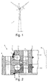
Figur 1 zeigt ein Ausführungsbeispiel einer Windkraftanlage gemäß der Erfindung in einer Frontalansicht. - Die
Figur 2 zeigt ein Ausführungsbeispiel einer erfindungsgemäßen Wälzlageranordnung in einer Schnittdarstellung. - Die
Figur 3 zeigt die Flächenpressung zwischen dem kugelförmigen Wälzkörper und der Laufbahn in Abhängigkeit von dem Tragwinkel für zwei typische Lastfälle der inFigur 2 gezeigten Wälzlageranordnung. - Die
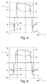
Figur 4 zeigt die Kontaktgrenzen der kugelförmigen Wälzkörper über der Abwicklung des Lagerumfangs für einen ersten Lastfall der inFigur 2 gezeigten Wälzlageranordnung mit einem Tragwinkel von 60 Grad. - Die
Figur 5 zeigt die Kontaktgrenzen der kugelförmigen Wälzkörper über der Abwicklung des Lagerumfangs für einen zweiten Lastfall der inFigur 2 gezeigten Wälzlageranordnung mit einem Tragwinkel von 60 Grad. - Die
Figur 6 zeigt die Kontaktgrenzen der kugelförmigen Wälzkörper über der Abwicklung des Lagerumfangs für den ersten Lastfall der inFigur 2 gezeigten Wälzlageranordnung mit einem Tragwinkel von 90 Grad. - Die
Figur 7 zeigt die Kontaktgrenzen der kugelförmigen Wälzkörper über der Abwicklung des Lagerumfangs für den zweiten Lastfall der inFigur 2 gezeigten Wälzlageranordnung mit einem Tragwinkel von 90 Grad. - In den verschiedenen Figuren sind gleiche Teile stets mit den gleichen Bezugszeichen versehen und werden daher in der Regel auch jeweils nur einmal benannt bzw. erwähnt.
- In der
Figur 1 ist eine Windkraftanlage 1 gezeigt, die einen auf einem Turm angeordneten Rotor 3 aufweist. Der Rotor 3 ist über ein Azimut-Lager gegenüber dem Turm in Azimut drehbar gelagert. An dem Rotor 3 sind mehrere Rotorblätter 2 vorgesehen, welche zur Einstellung des Blattwinkels der einzelnen Rotorblätter 2 über Blattlager 4 drehbar an dem Rotor 3 gelagert sind. - Das Azimut-Lager und die Blattlager 4 sind als Großwälzlager mit einem Durchmesser im Bereich von 1 m bis 10 m, bevorzugt von 3 m bis 7 m, besonders bevorzugt von 4 m bis 6 m ausgebildet. Nachfolgend soll ein Blattlager 4 beschrieben werden, welches die Rotorblätter 2 mit dem Rotor 3 drehbar verbindet. Alternativ oder zusätzlich ist es möglich, ein Azimut-Lager der Windkraftanlage 1 wie nachfolgend beschrieben auszubilden.
- Das in der
Figur 2 dargestellte Blattlager 4 weist eine erfindungsgemäße Wälzlageranordnung auf. Die Wälzlageranordnung umfasst einen Innenring 5 sowie einen relativ zum Innenring 6 um eine Rotationsachse R drehbar angeordneten Außenring 6, wobei die Rotationsachse inFigur 2 nur schematisch dargestellt ist. Der mittelte Radius des Innenrings 5 ist kleiner als der mittlere Radius des Außenrings 6. Da der Außenradius des Innenrings 5 größer ist als der Innenradius des Außenrings 6 ergibt sich ein Bereich, in welchem sich der Innenring 5 und der Außenring 6 entlang der radialen Richtung überlappen. Diese Überlappung kommt dadurch zustande, dass die äußere Mantelfläche 7 des Innenrings 5 eine Nut 8 und die innere Mantelfläche 9 des Außenrings 6 einen in die Nut 8 eingreifenden Radialvorsprung 10 aufweist. Ferner überlappen sich der Innenring 5 und der Außenring 6 im Bereich des Radialvorsprungs 10 in axialer Richtung, d.h. in einer Richtung, die parallel zur Rotationsachse R der Wälzlageranordnung verläuft. - Am Innenring 5 sind zwei Laufbahnen 11, 12 für kugelförmige Wälzkörper 13, 14 angeordnet. Die Laufbahnen 11, 12 des Innenrings 5 sind im Bereich der Nut 8, insbesondere an den Innenseiten der Nut 8, vorgesehen. Der Außenring 6 weist ebenfalls zwei Laufbahnen 15, 16 auf, in welchen die kugelförmigen Wälzkörper 13, 14 geführt sind. Die Laufbahnen 15, 16 des Außenrings 6 sind an den Flanken des Radialvorsprungs 10, insbesondere im Übergangsbereich der Flanken und eine in Richtung des Innenrings 5 weisenden inneren Mantelfläche 19 des Radialvorsprungs 10, ausgebildet. Die Laufbahnen 11, 12, 15, 16 weisen eine Innenkontur mit einem kreislinienförmigen Querschnitt auf. Der Radius der der Innenkontur der Laufbahnen 11, 12, 15, 16 ist im Wesentlichen identisch, wobei der Radius geringfügig größer gewählt ist als der Radius der kugelförmigen Wälzkörper 13, 14. Alternativ können die Radien der Laufbahnen 11, 12, 15, 16, an welchen ein Wälzkörper 13,1 4 anliegt auch unterschiedlich sein. Durch die unterschiedlichen Radien der Laufbahnen 11, 12, 15, 16 und der kugelförmigen Wälzkörper 13, 14 berühren die kugelförmigen Wälzkörper 13, 14 die entsprechenden Laufbahnen 11, 12, 15, 15 in einem Berührungspunkt.
- Die Lage dieser Berührungspunkte definiert den Tragwinkel und ist abhängig von der relativen Lage der Mittelpunkte der kugelförmigen Wälzkörper 13, 14 und der Mittelpunkte derjenigen Kreise, welche die Innenkontur der Laufbahnen 11, 12, 15, 16 definieren. In dem Fall, dass die Mittelpunkte eines kugelförmigen Wälzkörpers 13 und die beiden Mittelpunkte derjenigen Kreise, welche die Innenkontur der Laufbahnen 11, 15 des Wälzkörpers 13 definieren, auf einer gemeinsamen Zylindermantelfläche um die Rotationsachse R der Wälzlageranordnung liegen, sind auch die Berührungspunkte zwischen dem Wälzkörper 13 und den entsprechenden Laufbahnen 11, 15 auf der gemeinsamen Zylindermantelfläche angeordnet. Es ergibt sich ein Tragwinkel, den eine Verbindungslinie zwischen den Zentren der Berührungspunkte des Wälzkörpers 13 mit dessen beiden Laufbahnen 11, 15 gegenüber einer zur Rotationsachse R senkrechten Ringebene E einschließt, von 90 Grad.
- Abweichend von der zuvor beschrieben Konstellation, ist bei der erfindungsgemäßen Wälzlageranordnung ein Tragwinkel im Bereich von 60 bis 65 Grad, bevorzugt von 63 bis 65 Grad, besonders bevorzugt von 60 oder 61 oder 62 oder 63 oder 64 oder 65 Grad vorgesehen. Dies wird dadurch erreicht, dass die Berührungspunkte zwischen dem ersten kugelförmigen Wälzkörper 13 und den entsprechenden Laufbahnen 11, 15 auf einer Kegelmantelfläche um die Rotationsachse R angeordnet sind. Ebenso sind die Berührungspunkte zwischen dem zweiten kugelförmigen Wälzkörper 14 und den entsprechenden Laufbahnen 12, 16 auf einer Kegelmantelfläche um die Rotationsachse R angeordnet. Insofern schließt eine Verbindungslinie zwischen den Berührungspunkten eines Wälzkörpers 13, 14 mit dessen beiden Laufbahnen 11, 12, 15, 16 gegenüber einer zur Rotationsachse R senkrechten Ringebene E einen Tragwinkel ein, welcher in dem zuvor genannten Bereich liegt bzw. den zuvor genannten Wert aufweist.
- Die Wälzlageranordnung weist neben den beiden Reihen von kugelförmigen Wälzkörpern 13, 14 zusätzlich ein radiales Zusatzlager 20 auf, in welchem eine Reihe von als Zylinderrollen ausgebildeten Wälzkörpern 21 enthalten ist. Das radiale Zusatzlager 20 ist in axialer Richtung zwischen den beiden Reihen von kugelförmigen Wälzkörpern 13, 14 angeordnet, insbesondere in der Mitte der Strecke zwischen den beiden Reihen. Die jeweiligen Drehachsen der Zylinderrollen verlaufen im Wesentlichen parallel zur Rotationsachse R, was bedeutet, dass diese einen Tragwinkel von weniger als 20 Grad, bevorzugt von weniger als 7 Grad, besonders bevorzugt von weniger als 3 Grad oder von im Wesentlichen 0 Grad aufweisen. An einer Stirnseite des Radialvorsprungs 10 ist eine Laufbahn 22 vorgesehen, in welcher die Zylinderrollen laufen. Eine weitere Laufbahn 23 für die Zylinderrollen ist in der umlaufenden Nut 8 ausgebildet. Diese Laufbahn 23 ist mittig in der Nut 8 angeordnet.
- Um das Einbringen der Wälzkörper 13, 14, 21 zu erleichtern, ist der Innenring 5 zweiteilig ausgebildet. Der Innenring 5 weist ein erstes Ringelement 5.1 und ein zweites Ringelement 5.2 auf, welche lösbar aneinander festlegbar sind, beispielsweise über eine Schraubverbindung.
- Die Vorteile, die sich durch die Wahl eines Tragwinkels im Bereich von 60 bis 65 Grad ergeben, sollen nachfolgend anhand der in den
Figuren 3 bis 7 dargestellten Diagramme näher erläutert werden. - Der Darstellung in
Figur 3 ist die auftretende Flächenpressung in N/mm2 zwischen einem Wälzkörper 13, 14, 21 und der entsprechenden Laufbahn 11, 12, 15, 16, 22, 23 in Abhängigkeit von dem Tragwinkel W für zwei typische Lastfälle dargestellt. Die obere durchgezogene Linie 50 bezeichnet die Flächenpressung eines kugelförmigen Wälzkörpers 13, 14 und der entsprechenden Laufbahn 11, 12, 15, 16 in einem ersten Lastfall. Die obere gestrichelte Linie 51 bezeichnet die Flächenpressung eines als Zylinderrolle ausgebildeten Wälzkörpers 21 und der entsprechenden Laufbahn 22, 23 für den ersten Lastfall. In einem zweiten Lastfall mit im Vergleich zum ersten Lastfall verringerter Last ergibt sich entsprechend die als untere durchgezogenen Linie 52 dargestellte Flächenpressung für den kugelförmigen Wälzkörper 13, 14 und die als untere gestrichelten Linie 53 gezeigte Flächenpressung für den als Zylinderrolle ausgebildeten Wälzkörper 21. - Es ist deutlich zu erkennen, dass die Belastung der kugelförmigen Wälzkörper 13, 14 bei einem Tragwinkel von 90 Grad minimal ist. Wird der Tragwinkel W zu kleineren Werten verändert, führt dies bei einer Wälzlageranordnung wie sie in
Fig. 2 gezeigt ist dazu, dass sich die Flächenpressung 50,52 der kugelförmigen Wälzkörper 13, 14 erhöht, während die Zylinderrollen 21 entlastet werden. Somit erhöht sich bei der erfindungsgemäßen Wälzlageranordnung mit einem Tragwinkel W im Bereich von 60 bis 65 Grad, bevorzugt von 63 bis 65 Grad, besonders bevorzugt von 60 oder 61 oder 62 oder 63 oder 64 oder 65 Grad, die Belastung der kugelförmigen Wälzkörper 13, 14 gegenüber einer Wälzlageranordnung mit einem Tragwinkel im Bereich um 90 Grad geringfügig. - Dieser Nachteil der gestiegenen Belastung der kugelförmigen Wälzlager geht allerdings mit dem Vorteil einher, dass sich mit abnehmendem Tragwinkel W die tragende Umfangslänge in den Reihen der kugelförmigen Wälzlager 13, 14 verringert, wie nachfolgend anhand der Darstellung in den
Figuren 4, 5 ,6 und 7 erläutert werden soll. - In der
Figur 4 ist für den ersten Lastfall ausFigur 3 der Druckwinkel D der kugelförmigen Wälzkörper 13, 14 über der Abwicklung des Lagerumfangs U aufgetragen. Hierbei bezeichnet das Bezugszeichen 100 den maximalen Druckwinkel der Reihe mit den ersten kugelförmigen Wälzkörpern 13 und das Bezugszeichen 101 den minimalen Druckwinkel der ersten kugelförmigen Wälzkörper 13. Der Mittelwert beider Druckwinkel 100, 101 (oder auch Kontaktgrenzen) entspricht dem Tragwinkel W. Insofern liegt der Tragwinkel bei 60 Grad. Für die Reihe mit den zweiten kugelförmigen Wälzkörpern 14 ist der maximale Druckwinkel mit 103 und der minimale Druckwinkel mit 102 bezeichnet. In den Bereichen, in welchen der maximale Druckwinkel mit dem minimalen Druckwinkel zusammenfällt, sind die Wälzkörper 13, 14 entlastet. - Die
Figur 5 zeigt eine entsprechende Darstellung für den zweiten Lastfall ausFigur 3 . - Zum Vergleich ist in der
Figur 6 eine entsprechende Darstellung für den ersten Lastfall ausFigur 3 gezeigt, wobei der Tragwinkel W bei 90 Grad gewählt ist. DieFigur 7 zeigt eine entsprechende Darstellung für den zweiten Lastfall und einen Tragwinkel von 90 Grad. - Es ist deutlich zu erkennen, dass bei einem Tragwinkel im Bereich von 60 bis 65 Grad, insbesondere bei einem Tragwinkel von 60 oder 61 oder 62 oder 63 oder 64 oder 65 Grad, ein Umfangsbereich gegeben ist, in welchen die kugelförmigen Wälzkörper 13, 14 belastet werden, welcher weniger als die Hälfte des Umfangs der Wälzlageranordnung einnimmt, vgl.
Figur 4 und 5 . Bei einem Tragwinkel von 90 Grad hingegen, beträgt der Umfangsbereich, in welchem die kugelförmigen Wälzkörper 13, 14 belastet werden, mehr als 180 Grad, vgl. Figur 6 und 7. Bei derartig großen Umfangsbereichen, in welchem die kugelförmigen Wälzkörper 13, 14 belastet werden, kommt es zu einer Überlappung der Umfangsbereiche, welche zu einer unerwünschten Verspannung des Radialvorsprungs 10 sowie zu unerwünschten Umfangskräften in der Reihe der kugelförmigen Wälzkörper 13, 14 und damit zu einer Drehwiderstandserhöhung führen kann. Insofern ist im Bereich von 60 bis 65 Grad, insbesondere bei einem Tragwinkel von 60 oder 61 oder 62 oder 63 oder 64 oder 65 Grad ein Optimum erreicht, wobei nur eine geringfügige Erhöhung der Belastung der kugelförmigen Wälzlager 13, 14 gegeben ist und gleichzeitig unerwünschte Effekte, die eine Drehwiderstandserhöhung zu Folge haben können, reduziert werden. - Die vorstehend beschriebene Wälzlageranordnung, insbesondere Großwälzlageranordnung, weist einen Innenring 5 und einen relativ zum Innenring 5 um eine Rotationsachse R drehbaren und in radialer Richtung überlappenden Außenring 6 auf, wobei zwischen dem Innenring 5 und dem Außenring 6 zwei in axialer Richtung zueinander versetzte Reihen von kugelförmigen Wälzkörpern 13, 14 angeordnet sind, wobei die Wälzkörper 13, 14 jeweils in am Innenring 5 und am Außenring 6 ausgebildeten Laufbahnen 11, 12, 15, 16 laufen, wobei der Innenring 5 und der Außenring 6 einander mittels eines am Innenring 5 oder am Außenring 6 ausgebildeten zwischen die zwei Reihen von Wälzkörpern 13, 14 vorspringenden Radialvorsprungs 10 in axialer Richtung überlappen, und wobei der Tragwinkel, den eine Verbindungslinie zwischen den Zentren der Berührungspunkte eines Wälzkörpers 13, 14 mit dessen beiden Laufbahnen 11, 12, 15, 16 gegenüber einer zur Rotationsachse R senkrechten Ringebene E einschließt, in einem Bereich von 60 bis 65 Grad, insbesondere bei einem Tragwinkel von 60 oder 61 oder 62 oder 63 oder 64 oder 65 Grad, liegt.
-
- 1
- Windkraftanlage
- 2
- Rotorblatt
- 3
- Rotor
- 4
- Blattlager
- 5
- Innenring
- 6
- Außenring
- 7
- Mantelfläche
- 8
- Nut
- 9
- Mantelfläche
- 10
- Radialvorsprung
- 11
- Laufbahn
- 12
- Laufbahn
- 13
- Wälzkörper
- 14
- Wälzkörper
- 15
- Laufbahn
- 16
- Laufbahn
- 19
- Mantelfläche
- 20
- Zusatzlager
- 21
- Wälzkörper
- 22
- Laufbahn
- 23
- Laufbahn
- E
- Ringebene
- P
- Flächenpressung
- R
- Rotationsachse
- W
- Tragwinkel
Claims (7)
- Wälzlageranordnung, insbesondere Großwälzlageranordnung, aufweisend einen Innenring (5) und einen relativ zum Innenring (5) um eine Rotationsachse (R) drehbaren und in radialer Richtung überlappenden Außenring (6), wobei zwischen dem Innenring (5) und dem Außenring (6) zwei in axialer Richtung zueinander versetzte Reihen von kugelförmigen Wälzkörpern (13, 14) angeordnet sind, wobei die Wälzkörper (13, 14) jeweils in am Innenring (5) und am Außenring (6) ausgebildeten Laufbahnen (11, 12, 15, 16) laufen, wobei der Innenring (5) und der Außenring (6) einander mittels eines am Innenring (5) oder am Außenring (6) ausgebildeten zwischen die zwei Reihen von Wälzkörpern (13, 14) vorspringenden Radialvorsprungs (10) in axialer Richtung überlappen,
dadurch gekennzeichnet, dass
der Tragwinkel, den eine Verbindungslinie zwischen den Zentren der Berührungspunkte eines Wälzkörpers (13, 14) mit dessen beiden Laufbahnen (11, 12, 15, 16) gegenüber einer zur Rotationsachse (R) senkrechten Ringebene (E) einschließt, in einem Bereich von 60 bis 65 Grad liegt. - Wälzlageranordnung nach Anspruch 1, wobei der Außenring (6) oder der Innenring (5) eine umlaufende Nut (8) aufweist, in welche der am Innenring (5) oder am Außenring (6) angeordnete Radialvorsprung (10) entgegen der radialen Richtung vorsteht.
- Wälzlageranordnung nach einem der vorhergehenden Ansprüche, wobei an den Flanken des Radialvorsprungs (10) Laufbahnen (11, 12, 15,1 6) für die kugelförmigen Wälzkörper (13, 14) ausgebildet sind.
- Wälzlageranordnung nach einem der vorhergehenden Ansprüche, wobei in axialer Richtung zwischen den beiden Reihen von Wälzkörpern (13, 14) ein radiales Zusatzlager (20) angeordnet ist.
- Wälzlageranordnung nach Anspruch 4, wobei das radiale Zusatzlager (20) Wälzkörper (21) in Form von Zylinderrollen aufweist, wobei die jeweiligen Drehachsen der Zylinderrollen im Wesentlichen parallel zur Rotationsachse (R) verlaufen, wobei eine Laufbahn (22) für die Zylinderrollen an einer Stirnseite des Radialvorsprungs (10) ausgebildet ist und wobei eine andere Laufbahn (23) für die Zylinderrollen mittig in der umlaufenden Nut (8) ausgebildet ist.
- Wälzlageranordnung nach einem der vorhergehenden Ansprüche, wobei die Wälzlageranordnung einen Durchmesser im Bereich von 1 m bis 10 m, bevorzugt von 3 m bis 7 m, besonders bevorzugt von 4 m bis 6 m aufweist.
- Blattlager für eine Windkraftanlage (1) aufweisend eine Wälzlageranordnung nach einem der vorhergehenden Ansprüche.
Applications Claiming Priority (1)
| Application Number | Priority Date | Filing Date | Title |
|---|---|---|---|
| DE102015110246.3A DE102015110246A1 (de) | 2015-06-25 | 2015-06-25 | Wälzlageranordnung und Blattlager für eine Windkraftanlage |
Publications (2)
| Publication Number | Publication Date |
|---|---|
| EP3109493A1 true EP3109493A1 (de) | 2016-12-28 |
| EP3109493B1 EP3109493B1 (de) | 2020-10-28 |
Family
ID=56148299
Family Applications (1)
| Application Number | Title | Priority Date | Filing Date |
|---|---|---|---|
| EP16175615.0A Revoked EP3109493B1 (de) | 2015-06-25 | 2016-06-22 | Wälzlageranordnung und blattlager für eine windkraftanlage |
Country Status (2)
| Country | Link |
|---|---|
| EP (1) | EP3109493B1 (de) |
| DE (1) | DE102015110246A1 (de) |
Cited By (5)
| Publication number | Priority date | Publication date | Assignee | Title |
|---|---|---|---|---|
| CN108105256A (zh) * | 2017-12-22 | 2018-06-01 | 瓦房店轴承集团国家轴承工程技术研究中心有限公司 | T形沟直角接触分体式变桨轴承 |
| CN109737006A (zh) * | 2018-12-29 | 2019-05-10 | 北京金风科创风电设备有限公司 | 一种轴承、风力发电机组的变桨装置及其变桨方法 |
| CN111749983A (zh) * | 2019-03-28 | 2020-10-09 | 新疆金风科技股份有限公司 | 轴承及风力发电机组的轴承系统 |
| CN111765166A (zh) * | 2020-08-13 | 2020-10-13 | 大连冶金轴承股份有限公司 | 一种组合式u型结构水平双排球回转轴承 |
| CN113767227A (zh) * | 2019-03-26 | 2021-12-07 | 利勃海尔比伯拉赫零部件有限公司 | 大型滚动轴承 |
Families Citing this family (2)
| Publication number | Priority date | Publication date | Assignee | Title |
|---|---|---|---|---|
| DE102016113785A1 (de) | 2016-07-27 | 2018-02-01 | Thyssenkrupp Ag | Verfahren zur Anstellwinkelverstellung eines Rotorblattes einer Windkraftanlage und Windkraftanlage |
| DE102016113786A1 (de) | 2016-07-27 | 2018-02-01 | Thyssenkrupp Ag | Verfahren zur Anstellwinkelverstellung eines Rotorblattes einer Windkraftanlage und Windkraftanlage |
Citations (5)
| Publication number | Priority date | Publication date | Assignee | Title |
|---|---|---|---|---|
| EP2087249B1 (de) | 2006-10-31 | 2011-07-20 | IMO Holding GmbH | Wälzlageranordnung |
| DE102010027011A1 (de) * | 2010-07-13 | 2012-01-19 | Schaeffler Kg | Drehverbindung, insbesondere zur Rotorblatt- oder Turmlagerung für eine Windkraftanlage sowie Rotorblatt- oder Turmlagerung mit dieser Drehverbindung |
| DE102012002203A1 (de) * | 2012-02-07 | 2013-08-08 | Imo Holding Gmbh | Wälzlageranordnung zur Lagerung von Teilen einer Windkraftanlage, sowie Windkraftanlage mit einem derart ausgestalteten Blattlager |
| WO2013117980A1 (de) * | 2012-02-07 | 2013-08-15 | Imo Holding Gmbh | Anordnung zur lagerung gegeneinander verdrehbarer teile einer energieanlage |
| CN203477083U (zh) * | 2013-08-26 | 2014-03-12 | 洛阳新能轴承制造有限公司 | 一种转盘轴承 |
Family Cites Families (8)
| Publication number | Priority date | Publication date | Assignee | Title |
|---|---|---|---|---|
| DE102007019482A1 (de) * | 2007-04-25 | 2008-11-06 | Schaeffler Kg | Mehrreihiges Großwälzlager, insbesondere Axial-Radiallager zur Hauptlagerung der Rotorwelle einer Windkraftanlage |
| DE102008049814A1 (de) * | 2008-09-30 | 2010-04-01 | Schaeffler Kg | Drehverbindung beispielsweise für eine Windenergieanlage sowie Windenergieanlage mit der Drehverbindung |
| DE102008062910A1 (de) * | 2008-12-23 | 2010-06-24 | Schaeffler Kg | Wälzlager für eine Radialkräfte, Axialkräfte und Kippmomente aufnehmende Drehlagerung |
| DE102009035749A1 (de) * | 2009-08-01 | 2011-02-03 | Schaeffler Technologies Gmbh & Co. Kg | Einlagerkonstruktion sowie Windkraftanlagen mit der Einlagerkonstruktion |
| DE102010013741A1 (de) | 2009-12-04 | 2011-06-09 | Imo Holding Gmbh | Kugellager |
| DE102012025600A1 (de) | 2012-12-31 | 2014-07-03 | Imo Holding Gmbh | Vorrichtung zur drehbaren Kopplung zweier Anlagen- oder Maschinenteile |
| DE102013216841A1 (de) | 2013-08-23 | 2015-02-26 | Schaeffler Technologies Gmbh & Co. Kg | Rotorblattlagerung |
| ES2654667T3 (es) | 2014-05-15 | 2018-02-14 | Imo Holding Gmbh | Rodamiento |
-
2015
- 2015-06-25 DE DE102015110246.3A patent/DE102015110246A1/de not_active Ceased
-
2016
- 2016-06-22 EP EP16175615.0A patent/EP3109493B1/de not_active Revoked
Patent Citations (5)
| Publication number | Priority date | Publication date | Assignee | Title |
|---|---|---|---|---|
| EP2087249B1 (de) | 2006-10-31 | 2011-07-20 | IMO Holding GmbH | Wälzlageranordnung |
| DE102010027011A1 (de) * | 2010-07-13 | 2012-01-19 | Schaeffler Kg | Drehverbindung, insbesondere zur Rotorblatt- oder Turmlagerung für eine Windkraftanlage sowie Rotorblatt- oder Turmlagerung mit dieser Drehverbindung |
| DE102012002203A1 (de) * | 2012-02-07 | 2013-08-08 | Imo Holding Gmbh | Wälzlageranordnung zur Lagerung von Teilen einer Windkraftanlage, sowie Windkraftanlage mit einem derart ausgestalteten Blattlager |
| WO2013117980A1 (de) * | 2012-02-07 | 2013-08-15 | Imo Holding Gmbh | Anordnung zur lagerung gegeneinander verdrehbarer teile einer energieanlage |
| CN203477083U (zh) * | 2013-08-26 | 2014-03-12 | 洛阳新能轴承制造有限公司 | 一种转盘轴承 |
Cited By (6)
| Publication number | Priority date | Publication date | Assignee | Title |
|---|---|---|---|---|
| CN108105256A (zh) * | 2017-12-22 | 2018-06-01 | 瓦房店轴承集团国家轴承工程技术研究中心有限公司 | T形沟直角接触分体式变桨轴承 |
| CN109737006A (zh) * | 2018-12-29 | 2019-05-10 | 北京金风科创风电设备有限公司 | 一种轴承、风力发电机组的变桨装置及其变桨方法 |
| CN113767227A (zh) * | 2019-03-26 | 2021-12-07 | 利勃海尔比伯拉赫零部件有限公司 | 大型滚动轴承 |
| CN113767227B (zh) * | 2019-03-26 | 2023-10-27 | 利勃海尔比伯拉赫零部件有限公司 | 大型滚动轴承 |
| CN111749983A (zh) * | 2019-03-28 | 2020-10-09 | 新疆金风科技股份有限公司 | 轴承及风力发电机组的轴承系统 |
| CN111765166A (zh) * | 2020-08-13 | 2020-10-13 | 大连冶金轴承股份有限公司 | 一种组合式u型结构水平双排球回转轴承 |
Also Published As
| Publication number | Publication date |
|---|---|
| EP3109493B1 (de) | 2020-10-28 |
| DE102015110246A1 (de) | 2016-12-29 |
Similar Documents
| Publication | Publication Date | Title |
|---|---|---|
| EP3109493B1 (de) | Wälzlageranordnung und blattlager für eine windkraftanlage | |
| EP3529508B1 (de) | Lagerelement | |
| EP2627921B1 (de) | Baugruppe als lageranordnung zur drehenden lagerung von maschinen- und anlagenteilen | |
| EP2715162B2 (de) | GROßWÄLZLAGER | |
| DE102010054318A1 (de) | Rotorlagerung einer Windkraftanlage | |
| EP2676042A1 (de) | Axial-radialwälzlager, insbesondere für die lagerung von rotorblättern an einer windkraftanlage | |
| EP3728835B1 (de) | Windkraftanlage mit rotornabenverlängerung | |
| WO2010037370A1 (de) | Drehverbindung, insbesondere wälzlager mit drei konzentrischen lagerringen und wälzkörperreihen mit gekreuzten rollen oder kugeln mit vierpunktkontakt für eine windenergieanlage | |
| WO2015150158A1 (de) | Wälzlageranordnung und windkraftanlage | |
| EP2126387A1 (de) | Wälzlager mit drehwinkelbegrenzer | |
| EP2507522B1 (de) | Kugellager | |
| EP3078869A1 (de) | Käfig für ein mehrreihiges wälzlager und mehrreihiges wälzlager für windkraftanlagen | |
| EP3565981B1 (de) | Mehrreihiges grosswälzlager | |
| DE202019101697U1 (de) | Großwälzlager | |
| DE102007019642B4 (de) | Fluiddynamisches Lagersystem | |
| DE102015112056A1 (de) | Wälzlageranordnung, insbesondere Großwälzlageranordnung, und Blattlager für eine Windkraftanlage | |
| EP3870869B1 (de) | Wälzlageranordnung und windkraftanlage | |
| DE102014203487A1 (de) | Kegelrollenlageranordnung und Verfahren zur Vorlasteinstellung | |
| DE202018100216U1 (de) | Mehrreihiges Wälzlager | |
| EP3408549B1 (de) | Wälzlager, windkraftanlage und verfahren zum betrieb eines wälzlagers | |
| DE102010053671A1 (de) | Mehrreihiges Wälzlager und Rotorlagerung einer Windkraftanlage | |
| EP2944836B1 (de) | Wälzlager | |
| DE2942531C2 (de) | Spannvorrichtung zur Befestigung eines Nabenansatzes auf einer Welle | |
| WO2025099270A1 (de) | Gleitlagervorrichtung | |
| WO2015144580A1 (de) | Pendelrollenlager |
Legal Events
| Date | Code | Title | Description |
|---|---|---|---|
| PUAI | Public reference made under article 153(3) epc to a published international application that has entered the european phase |
Free format text: ORIGINAL CODE: 0009012 |
|
| STAA | Information on the status of an ep patent application or granted ep patent |
Free format text: STATUS: THE APPLICATION HAS BEEN PUBLISHED |
|
| AK | Designated contracting states |
Kind code of ref document: A1 Designated state(s): AL AT BE BG CH CY CZ DE DK EE ES FI FR GB GR HR HU IE IS IT LI LT LU LV MC MK MT NL NO PL PT RO RS SE SI SK SM TR |
|
| AX | Request for extension of the european patent |
Extension state: BA ME |
|
| RAP1 | Party data changed (applicant data changed or rights of an application transferred) |
Owner name: THYSSENKRUPP ROTHE ERDE GMBH Owner name: THYSSENKRUPP AG |
|
| STAA | Information on the status of an ep patent application or granted ep patent |
Free format text: STATUS: REQUEST FOR EXAMINATION WAS MADE |
|
| 17P | Request for examination filed |
Effective date: 20170628 |
|
| RBV | Designated contracting states (corrected) |
Designated state(s): AL AT BE BG CH CY CZ DE DK EE ES FI FR GB GR HR HU IE IS IT LI LT LU LV MC MK MT NL NO PL PT RO RS SE SI SK SM TR |
|
| RAP1 | Party data changed (applicant data changed or rights of an application transferred) |
Owner name: THYSSENKRUPP ROTHE ERDE GMBH Owner name: THYSSENKRUPP AG |
|
| STAA | Information on the status of an ep patent application or granted ep patent |
Free format text: STATUS: EXAMINATION IS IN PROGRESS |
|
| 17Q | First examination report despatched |
Effective date: 20190502 |
|
| RAP1 | Party data changed (applicant data changed or rights of an application transferred) |
Owner name: THYSSENKRUPP ROTHE ERDE GERMANY GMBH Owner name: THYSSENKRUPP AG |
|
| GRAJ | Information related to disapproval of communication of intention to grant by the applicant or resumption of examination proceedings by the epo deleted |
Free format text: ORIGINAL CODE: EPIDOSDIGR1 |
|
| GRAP | Despatch of communication of intention to grant a patent |
Free format text: ORIGINAL CODE: EPIDOSNIGR1 |
|
| GRAP | Despatch of communication of intention to grant a patent |
Free format text: ORIGINAL CODE: EPIDOSNIGR1 |
|
| STAA | Information on the status of an ep patent application or granted ep patent |
Free format text: STATUS: GRANT OF PATENT IS INTENDED |
|
| INTG | Intention to grant announced |
Effective date: 20200407 |
|
| GRAJ | Information related to disapproval of communication of intention to grant by the applicant or resumption of examination proceedings by the epo deleted |
Free format text: ORIGINAL CODE: EPIDOSDIGR1 |
|
| GRAP | Despatch of communication of intention to grant a patent |
Free format text: ORIGINAL CODE: EPIDOSNIGR1 |
|
| GRAS | Grant fee paid |
Free format text: ORIGINAL CODE: EPIDOSNIGR3 |
|
| INTG | Intention to grant announced |
Effective date: 20200820 |
|
| GRAA | (expected) grant |
Free format text: ORIGINAL CODE: 0009210 |
|
| STAA | Information on the status of an ep patent application or granted ep patent |
Free format text: STATUS: THE PATENT HAS BEEN GRANTED |
|
| AK | Designated contracting states |
Kind code of ref document: B1 Designated state(s): AL AT BE BG CH CY CZ DE DK EE ES FI FR GB GR HR HU IE IS IT LI LT LU LV MC MK MT NL NO PL PT RO RS SE SI SK SM TR |
|
| REG | Reference to a national code |
Ref country code: GB Ref legal event code: FG4D Free format text: NOT ENGLISH |
|
| REG | Reference to a national code |
Ref country code: CH Ref legal event code: EP |
|
| REG | Reference to a national code |
Ref country code: DE Ref legal event code: R096 Ref document number: 502016011531 Country of ref document: DE |
|
| REG | Reference to a national code |
Ref country code: AT Ref legal event code: REF Ref document number: 1328535 Country of ref document: AT Kind code of ref document: T Effective date: 20201115 |
|
| REG | Reference to a national code |
Ref country code: IE Ref legal event code: FG4D Free format text: LANGUAGE OF EP DOCUMENT: GERMAN |
|
| REG | Reference to a national code |
Ref country code: NL Ref legal event code: MP Effective date: 20201028 |
|
| PG25 | Lapsed in a contracting state [announced via postgrant information from national office to epo] |
Ref country code: GR Free format text: LAPSE BECAUSE OF FAILURE TO SUBMIT A TRANSLATION OF THE DESCRIPTION OR TO PAY THE FEE WITHIN THE PRESCRIBED TIME-LIMIT Effective date: 20210129 Ref country code: FI Free format text: LAPSE BECAUSE OF FAILURE TO SUBMIT A TRANSLATION OF THE DESCRIPTION OR TO PAY THE FEE WITHIN THE PRESCRIBED TIME-LIMIT Effective date: 20201028 Ref country code: PT Free format text: LAPSE BECAUSE OF FAILURE TO SUBMIT A TRANSLATION OF THE DESCRIPTION OR TO PAY THE FEE WITHIN THE PRESCRIBED TIME-LIMIT Effective date: 20210301 Ref country code: RS Free format text: LAPSE BECAUSE OF FAILURE TO SUBMIT A TRANSLATION OF THE DESCRIPTION OR TO PAY THE FEE WITHIN THE PRESCRIBED TIME-LIMIT Effective date: 20201028 Ref country code: NL Free format text: LAPSE BECAUSE OF FAILURE TO SUBMIT A TRANSLATION OF THE DESCRIPTION OR TO PAY THE FEE WITHIN THE PRESCRIBED TIME-LIMIT Effective date: 20201028 Ref country code: NO Free format text: LAPSE BECAUSE OF FAILURE TO SUBMIT A TRANSLATION OF THE DESCRIPTION OR TO PAY THE FEE WITHIN THE PRESCRIBED TIME-LIMIT Effective date: 20210128 |
|
| REG | Reference to a national code |
Ref country code: LT Ref legal event code: MG4D |
|
| PG25 | Lapsed in a contracting state [announced via postgrant information from national office to epo] |
Ref country code: ES Free format text: LAPSE BECAUSE OF FAILURE TO SUBMIT A TRANSLATION OF THE DESCRIPTION OR TO PAY THE FEE WITHIN THE PRESCRIBED TIME-LIMIT Effective date: 20201028 Ref country code: PL Free format text: LAPSE BECAUSE OF FAILURE TO SUBMIT A TRANSLATION OF THE DESCRIPTION OR TO PAY THE FEE WITHIN THE PRESCRIBED TIME-LIMIT Effective date: 20201028 Ref country code: SE Free format text: LAPSE BECAUSE OF FAILURE TO SUBMIT A TRANSLATION OF THE DESCRIPTION OR TO PAY THE FEE WITHIN THE PRESCRIBED TIME-LIMIT Effective date: 20201028 Ref country code: IS Free format text: LAPSE BECAUSE OF FAILURE TO SUBMIT A TRANSLATION OF THE DESCRIPTION OR TO PAY THE FEE WITHIN THE PRESCRIBED TIME-LIMIT Effective date: 20210228 Ref country code: LV Free format text: LAPSE BECAUSE OF FAILURE TO SUBMIT A TRANSLATION OF THE DESCRIPTION OR TO PAY THE FEE WITHIN THE PRESCRIBED TIME-LIMIT Effective date: 20201028 Ref country code: BG Free format text: LAPSE BECAUSE OF FAILURE TO SUBMIT A TRANSLATION OF THE DESCRIPTION OR TO PAY THE FEE WITHIN THE PRESCRIBED TIME-LIMIT Effective date: 20210128 |
|
| PG25 | Lapsed in a contracting state [announced via postgrant information from national office to epo] |
Ref country code: HR Free format text: LAPSE BECAUSE OF FAILURE TO SUBMIT A TRANSLATION OF THE DESCRIPTION OR TO PAY THE FEE WITHIN THE PRESCRIBED TIME-LIMIT Effective date: 20201028 |
|
| REG | Reference to a national code |
Ref country code: DE Ref legal event code: R026 Ref document number: 502016011531 Country of ref document: DE |
|
| PG25 | Lapsed in a contracting state [announced via postgrant information from national office to epo] |
Ref country code: EE Free format text: LAPSE BECAUSE OF FAILURE TO SUBMIT A TRANSLATION OF THE DESCRIPTION OR TO PAY THE FEE WITHIN THE PRESCRIBED TIME-LIMIT Effective date: 20201028 Ref country code: CZ Free format text: LAPSE BECAUSE OF FAILURE TO SUBMIT A TRANSLATION OF THE DESCRIPTION OR TO PAY THE FEE WITHIN THE PRESCRIBED TIME-LIMIT Effective date: 20201028 Ref country code: LT Free format text: LAPSE BECAUSE OF FAILURE TO SUBMIT A TRANSLATION OF THE DESCRIPTION OR TO PAY THE FEE WITHIN THE PRESCRIBED TIME-LIMIT Effective date: 20201028 Ref country code: SM Free format text: LAPSE BECAUSE OF FAILURE TO SUBMIT A TRANSLATION OF THE DESCRIPTION OR TO PAY THE FEE WITHIN THE PRESCRIBED TIME-LIMIT Effective date: 20201028 Ref country code: RO Free format text: LAPSE BECAUSE OF FAILURE TO SUBMIT A TRANSLATION OF THE DESCRIPTION OR TO PAY THE FEE WITHIN THE PRESCRIBED TIME-LIMIT Effective date: 20201028 Ref country code: SK Free format text: LAPSE BECAUSE OF FAILURE TO SUBMIT A TRANSLATION OF THE DESCRIPTION OR TO PAY THE FEE WITHIN THE PRESCRIBED TIME-LIMIT Effective date: 20201028 |
|
| PGFP | Annual fee paid to national office [announced via postgrant information from national office to epo] |
Ref country code: DE Payment date: 20210618 Year of fee payment: 6 |
|
| PLBI | Opposition filed |
Free format text: ORIGINAL CODE: 0009260 |
|
| PLAX | Notice of opposition and request to file observation + time limit sent |
Free format text: ORIGINAL CODE: EPIDOSNOBS2 |
|
| PG25 | Lapsed in a contracting state [announced via postgrant information from national office to epo] |
Ref country code: DK Free format text: LAPSE BECAUSE OF FAILURE TO SUBMIT A TRANSLATION OF THE DESCRIPTION OR TO PAY THE FEE WITHIN THE PRESCRIBED TIME-LIMIT Effective date: 20201028 |
|
| 26 | Opposition filed |
Opponent name: IMO GMBH & CO. KG Effective date: 20210727 |
|
| PG25 | Lapsed in a contracting state [announced via postgrant information from national office to epo] |
Ref country code: AL Free format text: LAPSE BECAUSE OF FAILURE TO SUBMIT A TRANSLATION OF THE DESCRIPTION OR TO PAY THE FEE WITHIN THE PRESCRIBED TIME-LIMIT Effective date: 20201028 Ref country code: IT Free format text: LAPSE BECAUSE OF FAILURE TO SUBMIT A TRANSLATION OF THE DESCRIPTION OR TO PAY THE FEE WITHIN THE PRESCRIBED TIME-LIMIT Effective date: 20201028 |
|
| PG25 | Lapsed in a contracting state [announced via postgrant information from national office to epo] |
Ref country code: SI Free format text: LAPSE BECAUSE OF FAILURE TO SUBMIT A TRANSLATION OF THE DESCRIPTION OR TO PAY THE FEE WITHIN THE PRESCRIBED TIME-LIMIT Effective date: 20201028 |
|
| PLBB | Reply of patent proprietor to notice(s) of opposition received |
Free format text: ORIGINAL CODE: EPIDOSNOBS3 |
|
| PG25 | Lapsed in a contracting state [announced via postgrant information from national office to epo] |
Ref country code: MC Free format text: LAPSE BECAUSE OF FAILURE TO SUBMIT A TRANSLATION OF THE DESCRIPTION OR TO PAY THE FEE WITHIN THE PRESCRIBED TIME-LIMIT Effective date: 20201028 |
|
| REG | Reference to a national code |
Ref country code: CH Ref legal event code: PL |
|
| GBPC | Gb: european patent ceased through non-payment of renewal fee |
Effective date: 20210622 |
|
| REG | Reference to a national code |
Ref country code: BE Ref legal event code: MM Effective date: 20210630 |
|
| PG25 | Lapsed in a contracting state [announced via postgrant information from national office to epo] |
Ref country code: LU Free format text: LAPSE BECAUSE OF NON-PAYMENT OF DUE FEES Effective date: 20210622 |
|
| PG25 | Lapsed in a contracting state [announced via postgrant information from national office to epo] |
Ref country code: LI Free format text: LAPSE BECAUSE OF NON-PAYMENT OF DUE FEES Effective date: 20210630 Ref country code: IE Free format text: LAPSE BECAUSE OF NON-PAYMENT OF DUE FEES Effective date: 20210622 Ref country code: GB Free format text: LAPSE BECAUSE OF NON-PAYMENT OF DUE FEES Effective date: 20210622 Ref country code: CH Free format text: LAPSE BECAUSE OF NON-PAYMENT OF DUE FEES Effective date: 20210630 |
|
| PG25 | Lapsed in a contracting state [announced via postgrant information from national office to epo] |
Ref country code: IS Free format text: LAPSE BECAUSE OF FAILURE TO SUBMIT A TRANSLATION OF THE DESCRIPTION OR TO PAY THE FEE WITHIN THE PRESCRIBED TIME-LIMIT Effective date: 20210228 Ref country code: FR Free format text: LAPSE BECAUSE OF NON-PAYMENT OF DUE FEES Effective date: 20210630 |
|
| PG25 | Lapsed in a contracting state [announced via postgrant information from national office to epo] |
Ref country code: BE Free format text: LAPSE BECAUSE OF NON-PAYMENT OF DUE FEES Effective date: 20210630 |
|
| REG | Reference to a national code |
Ref country code: AT Ref legal event code: MM01 Ref document number: 1328535 Country of ref document: AT Kind code of ref document: T Effective date: 20210622 |
|
| PG25 | Lapsed in a contracting state [announced via postgrant information from national office to epo] |
Ref country code: AT Free format text: LAPSE BECAUSE OF NON-PAYMENT OF DUE FEES Effective date: 20210622 |
|
| RDAF | Communication despatched that patent is revoked |
Free format text: ORIGINAL CODE: EPIDOSNREV1 |
|
| REG | Reference to a national code |
Ref country code: DE Ref legal event code: R103 Ref document number: 502016011531 Country of ref document: DE Ref country code: DE Ref legal event code: R064 Ref document number: 502016011531 Country of ref document: DE |
|
| REG | Reference to a national code |
Ref country code: DE Ref legal event code: R119 Ref document number: 502016011531 Country of ref document: DE |
|
| RDAG | Patent revoked |
Free format text: ORIGINAL CODE: 0009271 |
|
| STAA | Information on the status of an ep patent application or granted ep patent |
Free format text: STATUS: PATENT REVOKED |
|
| REG | Reference to a national code |
Ref country code: CH Ref legal event code: PL |
|
| 27W | Patent revoked |
Effective date: 20221112 |
|
| REG | Reference to a national code |
Ref country code: AT Ref legal event code: MA03 Ref document number: 1328535 Country of ref document: AT Kind code of ref document: T Effective date: 20221112 |
|
| PG25 | Lapsed in a contracting state [announced via postgrant information from national office to epo] |
Ref country code: CY Free format text: LAPSE BECAUSE OF FAILURE TO SUBMIT A TRANSLATION OF THE DESCRIPTION OR TO PAY THE FEE WITHIN THE PRESCRIBED TIME-LIMIT Effective date: 20201028 |
|
| PG25 | Lapsed in a contracting state [announced via postgrant information from national office to epo] |
Ref country code: HU Free format text: LAPSE BECAUSE OF FAILURE TO SUBMIT A TRANSLATION OF THE DESCRIPTION OR TO PAY THE FEE WITHIN THE PRESCRIBED TIME-LIMIT; INVALID AB INITIO Effective date: 20160622 |
|
| PG25 | Lapsed in a contracting state [announced via postgrant information from national office to epo] |
Ref country code: MK Free format text: LAPSE BECAUSE OF FAILURE TO SUBMIT A TRANSLATION OF THE DESCRIPTION OR TO PAY THE FEE WITHIN THE PRESCRIBED TIME-LIMIT Effective date: 20201028 |
|
| PG25 | Lapsed in a contracting state [announced via postgrant information from national office to epo] |
Ref country code: MT Free format text: LAPSE BECAUSE OF FAILURE TO SUBMIT A TRANSLATION OF THE DESCRIPTION OR TO PAY THE FEE WITHIN THE PRESCRIBED TIME-LIMIT Effective date: 20201028 |
|
| PG25 | Lapsed in a contracting state [announced via postgrant information from national office to epo] |
Ref country code: TR Free format text: LAPSE BECAUSE OF FAILURE TO SUBMIT A TRANSLATION OF THE DESCRIPTION OR TO PAY THE FEE WITHIN THE PRESCRIBED TIME-LIMIT Effective date: 20201028 |