EP3109424A1 - Reduktionsmitteltank mit integriertem fluidkanal zum führen eines heizfluides - Google Patents
Reduktionsmitteltank mit integriertem fluidkanal zum führen eines heizfluides Download PDFInfo
- Publication number
- EP3109424A1 EP3109424A1 EP16001326.4A EP16001326A EP3109424A1 EP 3109424 A1 EP3109424 A1 EP 3109424A1 EP 16001326 A EP16001326 A EP 16001326A EP 3109424 A1 EP3109424 A1 EP 3109424A1
- Authority
- EP
- European Patent Office
- Prior art keywords
- tank
- reducing agent
- fluid channel
- segment
- agent tank
- Prior art date
- Legal status (The legal status is an assumption and is not a legal conclusion. Google has not performed a legal analysis and makes no representation as to the accuracy of the status listed.)
- Granted
Links
Images


Classifications
-
- F—MECHANICAL ENGINEERING; LIGHTING; HEATING; WEAPONS; BLASTING
- F01—MACHINES OR ENGINES IN GENERAL; ENGINE PLANTS IN GENERAL; STEAM ENGINES
- F01N—GAS-FLOW SILENCERS OR EXHAUST APPARATUS FOR MACHINES OR ENGINES IN GENERAL; GAS-FLOW SILENCERS OR EXHAUST APPARATUS FOR INTERNAL-COMBUSTION ENGINES
- F01N3/00—Exhaust or silencing apparatus having means for purifying, rendering innocuous, or otherwise treating exhaust
- F01N3/08—Exhaust or silencing apparatus having means for purifying, rendering innocuous, or otherwise treating exhaust for rendering innocuous
- F01N3/10—Exhaust or silencing apparatus having means for purifying, rendering innocuous, or otherwise treating exhaust for rendering innocuous by thermal or catalytic conversion of noxious components of exhaust
- F01N3/24—Exhaust or silencing apparatus having means for purifying, rendering innocuous, or otherwise treating exhaust for rendering innocuous by thermal or catalytic conversion of noxious components of exhaust characterised by constructional aspects of converting apparatus
- F01N3/28—Construction of catalytic reactors
- F01N3/2896—Liquid catalyst carrier
-
- F—MECHANICAL ENGINEERING; LIGHTING; HEATING; WEAPONS; BLASTING
- F01—MACHINES OR ENGINES IN GENERAL; ENGINE PLANTS IN GENERAL; STEAM ENGINES
- F01N—GAS-FLOW SILENCERS OR EXHAUST APPARATUS FOR MACHINES OR ENGINES IN GENERAL; GAS-FLOW SILENCERS OR EXHAUST APPARATUS FOR INTERNAL-COMBUSTION ENGINES
- F01N3/00—Exhaust or silencing apparatus having means for purifying, rendering innocuous, or otherwise treating exhaust
- F01N3/08—Exhaust or silencing apparatus having means for purifying, rendering innocuous, or otherwise treating exhaust for rendering innocuous
- F01N3/10—Exhaust or silencing apparatus having means for purifying, rendering innocuous, or otherwise treating exhaust for rendering innocuous by thermal or catalytic conversion of noxious components of exhaust
- F01N3/18—Exhaust or silencing apparatus having means for purifying, rendering innocuous, or otherwise treating exhaust for rendering innocuous by thermal or catalytic conversion of noxious components of exhaust characterised by methods of operation; Control
- F01N3/20—Exhaust or silencing apparatus having means for purifying, rendering innocuous, or otherwise treating exhaust for rendering innocuous by thermal or catalytic conversion of noxious components of exhaust characterised by methods of operation; Control specially adapted for catalytic conversion
- F01N3/206—Adding periodically or continuously substances to exhaust gases for promoting purification, e.g. catalytic material in liquid form, NOx reducing agents
-
- F—MECHANICAL ENGINEERING; LIGHTING; HEATING; WEAPONS; BLASTING
- F01—MACHINES OR ENGINES IN GENERAL; ENGINE PLANTS IN GENERAL; STEAM ENGINES
- F01N—GAS-FLOW SILENCERS OR EXHAUST APPARATUS FOR MACHINES OR ENGINES IN GENERAL; GAS-FLOW SILENCERS OR EXHAUST APPARATUS FOR INTERNAL-COMBUSTION ENGINES
- F01N3/00—Exhaust or silencing apparatus having means for purifying, rendering innocuous, or otherwise treating exhaust
- F01N3/08—Exhaust or silencing apparatus having means for purifying, rendering innocuous, or otherwise treating exhaust for rendering innocuous
- F01N3/10—Exhaust or silencing apparatus having means for purifying, rendering innocuous, or otherwise treating exhaust for rendering innocuous by thermal or catalytic conversion of noxious components of exhaust
- F01N3/18—Exhaust or silencing apparatus having means for purifying, rendering innocuous, or otherwise treating exhaust for rendering innocuous by thermal or catalytic conversion of noxious components of exhaust characterised by methods of operation; Control
- F01N3/20—Exhaust or silencing apparatus having means for purifying, rendering innocuous, or otherwise treating exhaust for rendering innocuous by thermal or catalytic conversion of noxious components of exhaust characterised by methods of operation; Control specially adapted for catalytic conversion
- F01N3/206—Adding periodically or continuously substances to exhaust gases for promoting purification, e.g. catalytic material in liquid form, NOx reducing agents
- F01N3/2066—Selective catalytic reduction [SCR]
-
- F—MECHANICAL ENGINEERING; LIGHTING; HEATING; WEAPONS; BLASTING
- F01—MACHINES OR ENGINES IN GENERAL; ENGINE PLANTS IN GENERAL; STEAM ENGINES
- F01N—GAS-FLOW SILENCERS OR EXHAUST APPARATUS FOR MACHINES OR ENGINES IN GENERAL; GAS-FLOW SILENCERS OR EXHAUST APPARATUS FOR INTERNAL-COMBUSTION ENGINES
- F01N2610/00—Adding substances to exhaust gases
- F01N2610/02—Adding substances to exhaust gases the substance being ammonia or urea
-
- F—MECHANICAL ENGINEERING; LIGHTING; HEATING; WEAPONS; BLASTING
- F01—MACHINES OR ENGINES IN GENERAL; ENGINE PLANTS IN GENERAL; STEAM ENGINES
- F01N—GAS-FLOW SILENCERS OR EXHAUST APPARATUS FOR MACHINES OR ENGINES IN GENERAL; GAS-FLOW SILENCERS OR EXHAUST APPARATUS FOR INTERNAL-COMBUSTION ENGINES
- F01N2610/00—Adding substances to exhaust gases
- F01N2610/10—Adding substances to exhaust gases the substance being heated, e.g. by heating tank or supply line of the added substance
-
- F—MECHANICAL ENGINEERING; LIGHTING; HEATING; WEAPONS; BLASTING
- F01—MACHINES OR ENGINES IN GENERAL; ENGINE PLANTS IN GENERAL; STEAM ENGINES
- F01N—GAS-FLOW SILENCERS OR EXHAUST APPARATUS FOR MACHINES OR ENGINES IN GENERAL; GAS-FLOW SILENCERS OR EXHAUST APPARATUS FOR INTERNAL-COMBUSTION ENGINES
- F01N2610/00—Adding substances to exhaust gases
- F01N2610/14—Arrangements for the supply of substances, e.g. conduits
- F01N2610/1406—Storage means for substances, e.g. tanks or reservoirs
-
- F—MECHANICAL ENGINEERING; LIGHTING; HEATING; WEAPONS; BLASTING
- F01—MACHINES OR ENGINES IN GENERAL; ENGINE PLANTS IN GENERAL; STEAM ENGINES
- F01N—GAS-FLOW SILENCERS OR EXHAUST APPARATUS FOR MACHINES OR ENGINES IN GENERAL; GAS-FLOW SILENCERS OR EXHAUST APPARATUS FOR INTERNAL-COMBUSTION ENGINES
- F01N2610/00—Adding substances to exhaust gases
- F01N2610/14—Arrangements for the supply of substances, e.g. conduits
- F01N2610/1486—Means to prevent the substance from freezing
-
- Y—GENERAL TAGGING OF NEW TECHNOLOGICAL DEVELOPMENTS; GENERAL TAGGING OF CROSS-SECTIONAL TECHNOLOGIES SPANNING OVER SEVERAL SECTIONS OF THE IPC; TECHNICAL SUBJECTS COVERED BY FORMER USPC CROSS-REFERENCE ART COLLECTIONS [XRACs] AND DIGESTS
- Y02—TECHNOLOGIES OR APPLICATIONS FOR MITIGATION OR ADAPTATION AGAINST CLIMATE CHANGE
- Y02A—TECHNOLOGIES FOR ADAPTATION TO CLIMATE CHANGE
- Y02A50/00—TECHNOLOGIES FOR ADAPTATION TO CLIMATE CHANGE in human health protection, e.g. against extreme weather
- Y02A50/20—Air quality improvement or preservation, e.g. vehicle emission control or emission reduction by using catalytic converters
-
- Y—GENERAL TAGGING OF NEW TECHNOLOGICAL DEVELOPMENTS; GENERAL TAGGING OF CROSS-SECTIONAL TECHNOLOGIES SPANNING OVER SEVERAL SECTIONS OF THE IPC; TECHNICAL SUBJECTS COVERED BY FORMER USPC CROSS-REFERENCE ART COLLECTIONS [XRACs] AND DIGESTS
- Y02—TECHNOLOGIES OR APPLICATIONS FOR MITIGATION OR ADAPTATION AGAINST CLIMATE CHANGE
- Y02T—CLIMATE CHANGE MITIGATION TECHNOLOGIES RELATED TO TRANSPORTATION
- Y02T10/00—Road transport of goods or passengers
- Y02T10/10—Internal combustion engine [ICE] based vehicles
- Y02T10/12—Improving ICE efficiencies
Definitions
- the invention relates to a reducing agent tank for a reducing agent and expediently for mounting on a motor vehicle, in particular a urea tank for an aqueous urea solution.
- Motor vehicle reducing agent tanks for receiving a reducing agent are known in the prior art in various embodiments.
- z. B. DE 10 2011 108 213 A1 a heated reducing agent tank, which can be heated by electrical heating elements and the reducing agent can be transported via a tank-external delivery module.
- An object of the invention is to provide an alternative and / or improved reducing agent tank for a reducing agent.
- the invention provides a reducing agent tank for a reducing agent, preferably a urea tank for receiving an aqueous urea solution, for. As a urea-water mixture.
- the reducing agent tank is expediently used for mounting on a motor vehicle, preferably a commercial vehicle, in particular a truck or omnibus.
- the reducing agent is used in particular for supplying an exhaust gas purification system, for. B. a working based on the catalytic reduction exhaust purification system.
- the reducing agent tank comprises a housing for receiving the reducing agent, a tank segment and preferably a delivery module, for. B. a pump, for conveying the reducing agent.
- the tank segment is characterized in particular in that it has at least one integrated, in particular molded on or molded, fluid channel for guiding a fluid for heating, in particular for heating, of the reducing agent, preferably so, that the tank segment itself forms the fluid channel.
- the fluid channel is thus preferably a one-piece integral part of the tank segment.
- the fluid channel is therefore in particular no separate tube or tube to the tank segment.
- the tank segment is, expedient in its production or production-related, preferably carried out so that the fluid channel is integrated, in particular is formed, for. B. on or molded.
- the tank segment and / or the molded part are preferably an injection molded part and thus suitably made of a plastic material.
- the fluid channel is expediently formed on the inside of the tank segment.
- the tank segment has the delivery module and thus expediently the delivery module is integrated into the tank segment.
- the tank segment may in particular have a receiving opening for the delivery module.
- a fluid channel at least in sections, to extend essentially arcuately, in particular essentially in the form of a circular arc, around the receiving opening for the delivery module or the delivery module.
- a fluid channel can run meander-shaped at least in sections.
- the tank segment preferably comprises a substantially hood and / or sheet-like wall in order to create a preferably hood-shaped and / or sheet-like component.
- the wall is preferably used as the lower end cover for the housing.
- the tank segment expediently forms a boundary structure for the fluid channel, which delimits the fluid channel along its longitudinal extent.
- the delimiting structure preferably comprises at least two substantially parallel, z. B. rib-shaped wall elements and an inside part of the hood and / or sheet-like wall.
- the fluid channel is thus preferably bounded by substantially parallel wall elements and a part of the hood and / or sheet-like wall.
- tank segment and / or the delimiting structure leaves the fluid channel open to one side and the side and thus the fluid channel is closed by an adjacent tank element.
- the tank segment leaves the fluid channel open to the top, wherein the top and thus the fluid channel by an attached tank element, in particular a ground segment, z. B. a bottom plate, the housing is closed.
- the tank segment is preferably arranged below a bottom segment of the housing.
- the tank segment serves in particular as underfloor heating for the housing.
- the tank segment may include a fluid channel inlet and / or a fluid channel outlet.
- the fluid channel is preferably used for connection to a cooling circuit of an internal combustion engine of the motor vehicle.
- the tank segment z. B. have a fluid channel inlet and / or a fluid channel outlet.
- the fluid channel is preferably a heating channel.
- the tank segment may further comprise a plurality of stiffening ribs, in particular for stiffening and thus expedient reinforcement of the hood and / or sheet-like wall.
- the invention is not limited to a reducing agent tank but also includes a tank segment as disclosed herein.
- the invention comprises a motor vehicle, preferably a utility vehicle, in particular a bus or a lorry, with a reducing agent tank as disclosed herein.
- the motor vehicle preferably comprises an exhaust aftertreatment system, which can be supplied with the reducing agent from the reducing agent tank.
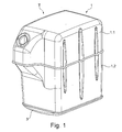
- FIG. 1 shows a perspective view of a reducing agent tank T for a reducing agent, in particular a urea tank for a preferably aqueous urea solution, for. B. so-called AdBlue.
- FIG. 2 shows another perspective view of the reducing agent tank T of FIG. 1 with an illustrative omission, so that for purposes of illustration into the reducing agent tank T can be looked into.
- the reducing agent tank T comprises a housing 1 of two mutually mounted housing sections 1.1 and 1.2 for receiving the reducing agent, a conveyor module 2 for conveying the reducing agent and a arranged below the housing 1 tank segment 3.
- the reducing agent tank T is used for mounting to a motor vehicle, preferably a commercial vehicle , in particular a truck or a bus.
- the tank segment 3 is provided with an integrated fluid channel 3.1 for guiding a fluid for heating the reducing agent, so that the tank segment 3 itself forms the fluid channel 3.1.
- the tank segment 3 and the fluid channel 3.1 are thus formed by one and the same molding, preferably an injection molded part.
- the tank segment 3 is carried out in its preparation so that the fluid channel 3.1 is integrated, in particular is formed with, for. B. on or molded.
- the tank segment 3 comprises a planar, expedient dome-shaped wall 3.3, on the inside of which the fluid channel 3.1 is formed.
- the sheet-like wall 3.3 forms expediently a lower end cover for the housing. 1
- the tank segment 3 forms a limiting structure 3.2 for the fluid channel 3.1.
- the delimiting structure 3.2 delimits the fluid channel 3.1 along its longitudinal extent L.
- the delimiting structure 3.2 comprises two substantially parallel wall elements 3.2 and an inside part of the planar wall 3.3.
- the two wall elements 3.2 limit the fluid channel 3.1 laterally.
- the sheet-like wall 3.3 limits the fluid channel 3.1 down.
- the tank segment 3 in particular the limiting structure 3.2 and 3.3, leaves the fluid channel 3.1 open to one side, namely in FIG. 2 towards the top.
- the open side so in FIG. 2 the top, and thus the fluid channel 3.1 is closed in the assembled state of the reducing agent tank T by an adjacent tank element, namely in FIG. 2 by a floor segment, expediently a bottom plate, of the housing 1.
- the tank segment 3 further comprises a receiving opening for the delivery module 2 for conveying the reducing agent, so that the delivery module 2 is expediently integrated into the tank segment 3.
- the fluid channel 3.1 extends at least in sections substantially in the shape of a circular arc and meandering around the receiving opening and thus around the delivery module 2.
- the tank segment 3 comprises a fluid channel inlet 3.4 and a fluid channel outlet 3.5.
- the fluid channel 3.1 serves for connection to a line for cooling fluid for cooling an internal combustion engine (eg an internal combustion engine, gasoline engine, etc.) of a motor vehicle FIGS. 1 and 2 It will be seen that the tank segment 3 serves as a bottom cover and at the same time as a bottom heater for the housing 1 and thus the reducing agent.
- an internal combustion engine eg an internal combustion engine, gasoline engine, etc.
- the tank segment 3 serves as a bottom cover and at the same time as a bottom heater for the housing 1 and thus the reducing agent.
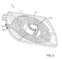
- FIGS. 1 and 2 show different perspective views of a tank segment 3 according to an embodiment of the invention, identical to the tank segment 3 of FIGS. 1 and 2 is executed.
- the tank segment 3 is provided with an integrated fluid channel 3.1 and the tank segment 3 including the fluid channel 3.1 is formed by one and the same molding.
- the fluid channel 3.1 is thus expediently an integral part of the tank segment 3.
- the fluid channel 3.1 is formed on the inside of the sheet-like wall 3.3 and is in the assembled state of the reducing agent tank 3 along its longitudinal extent L down through a part of the sheet-like wall 3.3, laterally through the two substantially parallel wall elements 3.2 and above by a bottom segment of the housing first limited.
- the fluid channel 3.1 extends arcuately and meandering around the receiving opening for the conveyor module. 2
- the tank segment 3 further comprises a plurality of stiffening ribs, in particular for stiffening the sheet-like wall 3.3
Landscapes
- Chemical & Material Sciences (AREA)
- Engineering & Computer Science (AREA)
- Chemical Kinetics & Catalysis (AREA)
- Health & Medical Sciences (AREA)
- Toxicology (AREA)
- Combustion & Propulsion (AREA)
- Mechanical Engineering (AREA)
- General Engineering & Computer Science (AREA)
- Exhaust Gas After Treatment (AREA)
Abstract
Description
- Die Erfindung betrifft einen Reduktionsmitteltank für ein Reduktionsmittel und zweckmäßig zur Montage an ein Kraftfahrzeug, insbesondere einen Harnstofftank für eine wässrige Harnstofflösung.
- Kraftfahrzeug-Reduktionsmitteltanks zur Aufnahme eines Reduktionsmittels sind im Stand der Technik in den unterschiedlichsten Ausführungsformen bekannt. So offenbart z. B.
DE 10 2011 108 213 A1 einen beheizbaren Reduktionsmitteltank, der über elektrische Heizelemente beheizbar ist und dessen Reduktionsmittel über ein Tank-externes Fördermodul befördert werden kann. - Eine Aufgabe der Erfindung ist es, einen alternativen und/oder verbesserten Reduktionsmitteltank für ein Reduktionsmittel zu schaffen.
- Diese Aufgabe kann mit den Merkmalen der unabhängigen Ansprüche gelöst werden. Vorteilhafte Weiterbildungen der Erfindung können den Unteransprüchen und der folgenden Beschreibung bevorzugter Ausführungsformen der Erfindung entnommen werden.
- Die Erfindung schafft einen Reduktionsmitteltank für ein Reduktionsmittel, vorzugsweise einen Harnstofftank zur Aufnahme einer wässrigen Harnstofflösung, z. B. eines Harnstoff-Wasser-Gemischs.
- Der Reduktionsmitteltank dient zweckmäßig zur Montage an ein Kraftfahrzeug, vorzugsweise Nutzfahrzeug, insbesondere Lastkraftwagen oder Omnibus.
- Das Reduktionsmittel dient insbesondere zur Versorgung eines Abgasreinigungssystems, z. B. eines auf Basis der katalytischen Reduktion arbeitenden Abgasreinigungssystems.
- Der Reduktionsmitteltank umfasst ein Gehäuse zur Aufnahme des Reduktionsmittels, ein Tanksegment und vorzugsweise ein Fördermodul, z. B. eine Pumpe, zum Fördern des Reduktionsmittels.
- Das Tanksegment zeichnet sich insbesondere dadurch aus, dass es zumindest einen integrierten, insbesondere an- oder eingeformten, Fluidkanal zum Führen eines Fluides zum Erwärmen, insbesondere zum Heizen, des Reduktionsmittels aufweist, vorzugsweise so, dass das Tanksegment selbst den Fluidkanal ausbildet. Der Fluidkanal ist somit vorzugsweise einstückig-integraler Teil des Tanksegments.
- Der Fluidkanal ist somit insbesondere kein zum Tanksegment separates Rohr oder Schlauch.
- Das Tanksegment wird, zweckmäßig in seiner Herstellung bzw. herstellungsbedingt, vorzugsweise so ausgeführt, dass der Fluidkanal mit integriert wird, insbesondere mit ausgeformt wird, z. B. ein- oder angeformt wird.
- Es ist möglich, dass ein und dasselbe Formteil das Tanksegment und den Fluidkanal ausbildet.
- Das Tanksegment und/oder das Formteil sind vorzugsweise ein Spritzgussteil und somit zweckmäßig aus einem Kunststoffmaterial gefertigt.
- Der Fluidkanal ist zweckmäßig auf der Innenseite des Tanksegments ausgebildet.
- Es ist möglich, dass das Tanksegment das Fördermodul aufweist und somit zweckmäßig das Fördermodul in das Tanksegment integriert ist. Hierzu kann das Tanksegment insbesondere eine Aufnahmeöffnung für das Fördermodul aufweisen.
- Es ist möglich, dass ein Fluidkanal zumindest abschnittsweise im Wesentlichen bogenförmig, insbesondere im Wesentlichen kreisbogenförmig um die Aufnahmeöffnung für das Fördermodul bzw. das Fördermodul verläuft. Alternativ oder ergänzend kann ein Fluidkanal zumindest abschnittsweise mäanderförmig verlaufen.
- Das Tanksegment umfasst vorzugsweise eine im Wesentlichen hauben- und/oder flächenförmige Wandung, um ein vorzugsweise hauben- und/oder flächenförmiges Bauteil zu schaffen. Die Wandung dient vorzugsweise als untere Abschlussabdeckung für das Gehäuse.
- Das Tanksegment bildet zweckmäßig eine Begrenzungsstruktur für den Fluidkanal, die den Fluidkanal entlang seiner Längserstreckung begrenzt.
- Die Begrenzungsstruktur umfasst vorzugsweise zumindest zwei im Wesentlichen parallel verlaufende, z. B. rippenförmige Wandelemente und einen innenseitigen Teil der hauben- und/oder flächenförmigen Wandung.
- Der Fluidkanal wird somit vorzugsweise durch im Wesentlichen parallel verlaufende Wandelemente und einen Teil der hauben- und/oder flächenförmigen Wandung begrenzt.
- Es ist möglich, dass das Tanksegment und/oder die Begrenzungsstruktur den Fluidkanal zu einer Seite hin offen lässt und die Seite und somit der Fluidkanal durch ein benachbartes Tankelement geschlossen wird.
- Vorzugsweise lässt das Tanksegment den Fluidkanal zur Oberseite hin offen, wobei die Oberseite und somit der Fluidkanal durch ein aufgesetztes Tankelement, insbesondere ein Bodensegment, z. B. eine Bodenplatte, des Gehäuses geschlossen wird.
- Das Tanksegment ist vorzugsweise unter einem Bodensegment des Gehäuses angeordnet. Das Tanksegment dient insbesondere als Bodenheizung für das Gehäuse.
- Das Tanksegment kann einen Fluidkanal-Einlass und/oder einen Fluidkanal-Auslass aufweisen.
- Der Fluidkanal dient vorzugsweise zur Verbindung mit einem Kühlkreislauf einer Verbrennungskraftmaschine des Kraftfahrzeugs. Hierzu kann das Tanksegment z. B. einen Fluidkanal-Einlass und/oder einen Fluidkanal-Auslass aufweisen.
- Der Fluidkanal ist vorzugsweise ein Heizkanal.
- Das Tanksegment kann ferner mehrere Versteifungsrippen aufweisen, insbesondere zur Aussteifung und somit zweckmäßigen Verstärkung der hauben- und/oder flächenförmigen Wandung.
- Die Erfindung ist nicht auf einen Reduktionsmitteltank begrenzt, sondern umfasst auch ein Tanksegment wie hierin offenbart.
- Des Weiteren umfasst die Erfindung ein Kraftfahrzeug, vorzugsweise ein Nutzfahrzeug, insbesondere einen Omnibus oder einen Lastkraftwagen, mit einem Reduktionsmitteltank wie hierin offenbart.
- Das Kraftfahrzeug umfasst vorzugsweise ein Abgasnachbehandlungssystem, das mit dem Reduktionsmittel aus dem Reduktionsmitteltank versorgt werden kann.
- Die zuvor beschriebenen bevorzugten Ausführungsformen und Merkmale der Erfindung sind miteinander kombinierbar. Andere vorteilhafte Weiterbildungen sind in den Unteransprüchen offenbart oder ergeben sich aus der folgenden Beschreibung bevorzugter Ausführungsformen der Erfindung in Verbindung mit den beigefügten Figuren.
- Figur 1
- zeigt eine perspektivische Ansicht eines Reduktionsmitteltanks gemäß einer Ausführungsform der Erfindung,
- Figur 2
- zeigt eine andere perspektivische Ansicht des Reduktionsmitteltanks der
Figur 1 mit einer illustrativen Weglassung, so dass zu Illustrationszwecken in den Reduktionsmitteltank hineingeschaut werden kann, - Figur 3
- zeigt eine perspektivische Ansicht eines Tanksegments gemäß einer Ausführungsform der Erfindung, und
- Figur 4
- zeigt eine andere perspektivische Ansicht des Tanksegments der
Figur 3 . -
Figur 1 zeigt eine perspektivische Ansicht eines Reduktionsmitteltanks T für ein Reduktionsmittel, insbesondere einen Harnstofftank für eine vorzugsweise wässrige Harnstofflösung, z. B. sogenanntem AdBlue.Figur 2 zeigt eine andere perspektivische Ansicht des Reduktionsmitteltanks T derFigur 1 mit einer illustrativen Weglassung, so dass zu Illustrationszwecken in den Reduktionsmitteltank T hineingeschaut werden kann. - Unter Bezugnahme auf die
Figuren 1 und2 umfasst der Reduktionsmitteltank T ein Gehäuse 1 aus zwei aneinander montierten Gehäuseabschnitten 1.1 und 1.2 zur Aufnahme des Reduktionsmittels, ein Fördermodul 2 zum Fördern des Reduktionsmittels und ein unter dem Gehäuse 1 angeordnetes Tanksegment 3. Der Reduktionsmitteltank T dient zur Montage an ein Kraftfahrzeug, vorzugsweise ein Nutzfahrzeug, insbesondere ein Lastkraftwagen oder einen Omnibus. - Das Tanksegment 3 ist mit einem integrierten Fluidkanal 3.1 zum Führen eines Fluids zum Erwärmen des Reduktionsmittels versehen, so dass das Tanksegment 3 selbst den Fluidkanal 3.1 ausbildet. Das Tanksegment 3 und der Fluidkanal 3.1 werden somit durch ein und dasselbe Formteil, vorzugsweise ein Spritzgussteil ausgebildet. Das Tanksegment 3 wird in seiner Herstellung so ausgeführt, dass der Fluidkanal 3.1 mit integriert wird, insbesondere mit ausgeformt wird, z. B. ein- oder angeformt wird.
- Das Tanksegment 3 umfasst eine flächenförmige, zweckmäßig haubenförmige Wandung 3.3, an deren Innenseite der Fluidkanal 3.1 ausgebildet ist. Die flächenförmige Wandung 3.3 bildet zweckmäßig eine untere Abschlussabdeckung für das Gehäuse 1.
- Das Tanksegment 3 bildet eine Begrenzungsstruktur 3.2 für den Fluidkanal 3.1. Die Begrenzungsstruktur 3.2 begrenzt den Fluidkanal 3.1 entlang seiner Längserstreckung L. Die Begrenzungsstruktur 3.2 umfasst zwei im Wesentlichen parallel verlaufende Wandelemente 3.2 und einen innenseitigen Teil der flächenförmigen Wandung 3.3. Die zwei Wandelemente 3.2 begrenzen den Fluidkanal 3.1 seitlich. Die flächenförmige Wandung 3.3 begrenzt den Fluidkanal 3.1 nach unten.
- Das Tanksegment 3, insbesondere die Begrenzungsstruktur 3.2 und 3.3, lässt den Fluidkanal 3.1 zu einer Seite hin offen, nämlich in
Figur 2 zur Oberseite hin. Die offene Seite, also inFigur 2 die Oberseite, und somit der Fluidkanal 3.1 wird im Montagezustand des Reduktionsmitteltanks T durch ein benachbartes Tankelement geschlossen, nämlich inFigur 2 durch ein Bodensegment, zweckmäßig eine Bodenplatte, des Gehäuses 1. - Das Tanksegment 3 umfasst ferner eine Aufnahmeöffnung für das Fördermodul 2 zum Fördern des Reduktionsmittels, so dass das Fördermodul 2 zweckmäßig in das Tanksegment 3 integriert ist. Der Fluidkanal 3.1 erstreckt sich zumindest abschnittsweise im Wesentlichen kreisbogenförmig und mäanderförmig um die Aufnahmeöffnung und somit um das Fördermodul 2.
- Das Tanksegment 3 umfasst einen Fluidkanal-Einlass 3.4 und einen Fluidkanal-Auslass 3.5.
- Der Fluidkanal 3.1 dient zur Verbindung mit einer Leitung für Kühlfluid zum Kühlen einer Verbrennungskraftmaschine (z. B. einem Verbrennungsmotor, Ottomotor, etc.) eines Kraftfahrzeugs.-Aus den
Figuren 1 und2 wird ersichtlich, dass das Tanksegment 3 als Bodenabdeckung und zugleich als Bodenheizung für das Gehäuse 1 und somit das Reduktionsmittel dient. - Die
Figuren 3 und4 zeigen unterschiedliche perspektivische Ansichten eines Tanksegments 3 gemäß einer Ausführungsform der Erfindung, das identisch zu dem Tanksegment 3 derFiguren 1 und2 ausgeführt ist. - Aus den
Figuren 3 und4 wird insbesondere nochmals ersichtlich, dass das Tanksegment 3 mit einem integrierten Fluidkanal 3.1 versehen ist und das Tanksegment 3 einschließlich des Fluidkanals 3.1 durch ein und dasselbe Formteil ausgebildet wird. Der Fluidkanal 3.1 ist somit zweckmäßig einstückig-integraler Teil des Tanksegments 3. - Der Fluidkanal 3.1 ist auf der Innenseite der flächenförmigen Wandung 3.3 ausgebildet und wird im Montagezustand des Reduktionsmitteltanks 3 entlang seiner Längserstreckung L unten durch einen Teil der flächenförmigen Wandung 3.3, seitlich durch die zwei im Wesentlichen parallel verlaufenden Wandelemente 3.2 und oben durch ein Bodensegment des Gehäuses 1 begrenzt. Der Fluidkanal 3.1 verläuft bogen- und mäanderförmig um die Aufnahmeöffnung für das Fördermodul 2.
- Das Tanksegment 3 umfasst ferner mehrere Versteifungsrippen, insbesondere zur Aussteifung der flächenförmigen Wandung 3.3
- Die Erfindung ist nicht auf die oben beschriebenen bevorzugten Ausführungsformen beschränkt. Vielmehr ist eine Vielzahl von Varianten und Abwandlungen möglich, die ebenfalls von dem Erfindungsgedanken Gebrauch machen und deshalb in den Schutzbereich fallen. - Darüber hinaus beansprucht die Erfindung auch Schutz für den Gegenstand und die Merkmale der Unteransprüche unabhängig von den in Bezug genommenen Merkmalen und Ansprüchen.
-
- T
- Reduktionsmitteltank, insbesondere Harnstofftank
- 1
- Gehäuse
- 1.1
- Gehäuseabschnitt
- 1.2
- Gehäuseabschnitt
- 2
- Fördermodul zum Fördern des Reduktionsmittels
- 3
- Tanksegment
- 3.1
- Fluidkanal, insbesondere Heizkanal zum Führen eines Fluides zum Erwärmen des Reduktionsmittels
- 3.2
- Begrenzungsstruktur für den Fluidkanal, insbesondere seitliche Begrenzungsstruktur
- 3.3
- Hauben- und/oder flächenförmige Wandung
- L
- Längserstreckung, insbesondere Längsrichtung, des Fluidkanals
Claims (14)
- Reduktionsmitteltank (T) für ein Reduktionsmittel und vorzugsweise zur Montage an ein Kraftfahrzeug, mit einem Gehäuse (1) zur Aufnahme des Reduktionsmittels, einem Tanksegment (3) und vorzugsweise einem Fördermodul (2) zum Fördern des Reduktionsmittels, dadurch gekennzeichnet, dass das Tanksegment (3) zumindest einen integrierten Fluidkanal (3.1) zum Führen eines Fluids zum Erwärmen des Reduktionsmittels aufweist, insbesondere so, dass das Tanksegment (3) selbst den Fluidkanal (3.1) ausbildet.
- Reduktionsmitteltank (T) nach Anspruch 1, dadurch gekennzeichnet, dass ein und dasselbe Formteil das Tanksegment (3) und den Fluidkanal (3.1) ausbildet.
- Reduktionsmitteltank (T) nach einem der vorhergehenden Ansprüche, dadurch gekennzeichnet, dass das Tanksegment (3) und/oder das Formteil ein Spritzgussteil sind.
- Reduktionsmitteltank (T) nach einem der vorhergehenden Ansprüche, dadurch gekennzeichnet, dass der Fluidkanal (3.1) auf einer Innenseite des Tanksegments (3) ausgebildet ist.
- Reduktionsmitteltank (T) nach einem der vorhergehenden Ansprüche, dadurch gekennzeichnet, dass das Tanksegment (3) das Fördermodul (2) aufweist und/oder eine Aufnahmeöffnung für das Fördermodul (2) aufweist.
- Reduktionsmitteltank (T) nach einem der vorhergehenden Ansprüche, dadurch gekennzeichnet, dass zumindest ein Fluidkanal (3.1) zumindest abschnittsweise bogenförmig um die Aufnahmeöffnung für das Fördermodul (2) und/oder mäanderförmig verläuft.
- Reduktionsmitteltank (T) nach einem der vorhergehenden Ansprüche, dadurch gekennzeichnet, dass das Tanksegment (3) eine hauben- und/oder flächenförmige Wandung (3.3) umfasst und die Wandung (3.3) eine vorzugsweise untere Abschlussabdeckung für das Gehäuse (1) bildet.
- Reduktionsmitteltank (T) nach einem der vorhergehenden Ansprüche, dadurch gekennzeichnet, dass der Fluidkanal (3.1) mittels einer durch das Tanksegment (3) gebildeten Begrenzungsstruktur (3.2) entlang seiner Längserstreckung (L) begrenzt wird.
- Reduktionsmitteltank (T) nach einem der vorhergehenden Ansprüche, dadurch gekennzeichnet, dass das Tanksegment (3) und/oder die Begrenzungsstruktur (3.2) den Fluidkanal (3.1) zu einer Seite hin offen lässt und die Seite und somit der Fluidkanal (3.1) durch ein benachbartes Tankelement geschlossen wird.
- Reduktionsmitteltank (T) nach einem der vorhergehenden Ansprüche, dadurch gekennzeichnet, dass das Tanksegment (3) und/oder die Begrenzungsstruktur (3.2) den Fluidkanal (3.1) zur Oberseite hin offen lässt und die Oberseite durch ein aufgesetztes Tankelement, insbesondere ein Bodensegment des Gehäuses (1), geschlossen wird.
- Reduktionsmitteltank (T) nach einem der vorhergehenden Ansprüche, dadurch gekennzeichnet, dass das Tanksegment (3) unter einem Bodensegment des Gehäuses (1) angeordnet ist und/oder als Bodenheizung für das Gehäuse (1) und somit das Reduktionsmittel dient.
- Reduktionsmitteltank (T) nach einem der vorhergehenden Ansprüche, dadurch gekennzeichnet, dass der Fluidkanal (3.1) mit einem Kühlkreislauf einer Verbrennungskraftmaschine des Kraftfahrzeugs verbindbar ist.
- Tanksegment (3) nach dem kennzeichnenden Teil eines der vorhergehenden Ansprüche für einen Reduktionsmitteltank (T) für ein Reduktionsmittel.
- Kraftfahrzeug, vorzugsweise Nutzfahrzeug, mit einem Reduktionsmitteltank (T) nach einem der Ansprüche 1 bis 12.
Applications Claiming Priority (1)
| Application Number | Priority Date | Filing Date | Title |
|---|---|---|---|
| DE102015008351.1A DE102015008351A1 (de) | 2015-06-27 | 2015-06-27 | Reduktionsmitteltank mit integriertem Fluidkanal zum Führen eines Heizfluides |
Publications (2)
| Publication Number | Publication Date |
|---|---|
| EP3109424A1 true EP3109424A1 (de) | 2016-12-28 |
| EP3109424B1 EP3109424B1 (de) | 2018-08-15 |
Family
ID=56235522
Family Applications (1)
| Application Number | Title | Priority Date | Filing Date |
|---|---|---|---|
| EP16001326.4A Active EP3109424B1 (de) | 2015-06-27 | 2016-06-13 | Reduktionsmitteltank mit integriertem fluidkanal zum führen eines heizfluides |
Country Status (5)
| Country | Link |
|---|---|
| EP (1) | EP3109424B1 (de) |
| CN (1) | CN106285859B (de) |
| BR (1) | BR102016014958B1 (de) |
| DE (1) | DE102015008351A1 (de) |
| RU (1) | RU2721060C2 (de) |
Citations (6)
| Publication number | Priority date | Publication date | Assignee | Title |
|---|---|---|---|---|
| DE20314557U1 (de) * | 2003-09-19 | 2003-11-20 | Sauermann, Franz, 86558 Hohenwart | Behälter für aggressive Flüssigkeiten mit Heiz- und/oder Kühlmöglichkeit |
| DE202005019499U1 (de) * | 2005-12-14 | 2006-02-09 | Man Nutzfahrzeuge Ag | Beheizung eines Tanks für Harnstoffwasserlösung |
| DE102010029269A1 (de) * | 2010-05-25 | 2011-12-01 | Robert Bosch Gmbh | Beheizbarer Tankbehälter |
| DE102011108213A1 (de) | 2011-07-21 | 2013-01-24 | Audi Ag | Beheizbarer Reduktionsmitteltank |
| DE102012020040A1 (de) * | 2012-10-12 | 2014-04-17 | Kautex Textron Gmbh & Co. Kg | Einrichtung zur Bevorratung und Förderung eines wässrigen Additivs |
| EP2733321A1 (de) * | 2012-08-28 | 2014-05-21 | Yapp Automotive Parts Co., Ltd. | Harnstofftank für kraftfahrzeug und verfahren zu seiner herstellung |
Family Cites Families (2)
| Publication number | Priority date | Publication date | Assignee | Title |
|---|---|---|---|---|
| GB0807173D0 (en) * | 2008-04-19 | 2008-05-21 | Agco Gmbh | Exhaust gas treatment system |
| DE102010004614B4 (de) * | 2010-01-13 | 2025-03-13 | Vitesco Technologies GmbH | Vorrichtung zur Bereitstellung von flüssigem Reduktionsmittel |
-
2015
- 2015-06-27 DE DE102015008351.1A patent/DE102015008351A1/de not_active Withdrawn
-
2016
- 2016-06-13 EP EP16001326.4A patent/EP3109424B1/de active Active
- 2016-06-24 BR BR102016014958-4A patent/BR102016014958B1/pt active IP Right Grant
- 2016-06-24 RU RU2016125223A patent/RU2721060C2/ru active
- 2016-06-27 CN CN201610475301.9A patent/CN106285859B/zh active Active
Patent Citations (6)
| Publication number | Priority date | Publication date | Assignee | Title |
|---|---|---|---|---|
| DE20314557U1 (de) * | 2003-09-19 | 2003-11-20 | Sauermann, Franz, 86558 Hohenwart | Behälter für aggressive Flüssigkeiten mit Heiz- und/oder Kühlmöglichkeit |
| DE202005019499U1 (de) * | 2005-12-14 | 2006-02-09 | Man Nutzfahrzeuge Ag | Beheizung eines Tanks für Harnstoffwasserlösung |
| DE102010029269A1 (de) * | 2010-05-25 | 2011-12-01 | Robert Bosch Gmbh | Beheizbarer Tankbehälter |
| DE102011108213A1 (de) | 2011-07-21 | 2013-01-24 | Audi Ag | Beheizbarer Reduktionsmitteltank |
| EP2733321A1 (de) * | 2012-08-28 | 2014-05-21 | Yapp Automotive Parts Co., Ltd. | Harnstofftank für kraftfahrzeug und verfahren zu seiner herstellung |
| DE102012020040A1 (de) * | 2012-10-12 | 2014-04-17 | Kautex Textron Gmbh & Co. Kg | Einrichtung zur Bevorratung und Förderung eines wässrigen Additivs |
Also Published As
| Publication number | Publication date |
|---|---|
| RU2016125223A (ru) | 2017-12-26 |
| BR102016014958B1 (pt) | 2022-11-16 |
| BR102016014958A8 (pt) | 2018-02-27 |
| RU2721060C2 (ru) | 2020-05-15 |
| EP3109424B1 (de) | 2018-08-15 |
| CN106285859A (zh) | 2017-01-04 |
| DE102015008351A1 (de) | 2016-12-29 |
| CN106285859B (zh) | 2020-10-30 |
Similar Documents
| Publication | Publication Date | Title |
|---|---|---|
| DE102016201557B3 (de) | Abgasnachbehandlungseinrichtung mit Katalysator sowie deren Anordnung in einem Kraftfahrzeug | |
| DE102007050272A1 (de) | Tank zur Bevorratung eines Reduktionsmittels | |
| DE102011088217A1 (de) | Dosieranordnung für ein flüssiges Abgasnachbehandlungsmittel und Dosierverfahren | |
| DE102008041723A1 (de) | Tank zur Bevorratung eines flüssigen Wirkstoffes | |
| WO2010063801A2 (de) | Flüssigkeitsbehälter für ein kraftfahrzeug | |
| DE102016206637A1 (de) | Behälteranordnung für ein Kraftfahrzeug | |
| EP3109425B1 (de) | Reduktionsmitteltank mit integriertem fluidkanal zum führen eines heizfluides | |
| DE102008042954A1 (de) | Dosiersystem für ein flüssiges Medium, insbesondere Harnstoff-Wasser-Lösung | |
| DE102009011018A1 (de) | Vorrichtung zum Zuführen eines Hilfsmittels zu einer Abgasnachbehandlungseinrichtung eines Kraftfahrzeugs | |
| EP3109424B1 (de) | Reduktionsmitteltank mit integriertem fluidkanal zum führen eines heizfluides | |
| WO2011138191A1 (de) | Behälter mit einer entnahmeleitung für eine betriebsflüssigkeit eines kraftfahrzeugs | |
| EP2748024B1 (de) | Tankanordnung sowie abgasreinigungseinrichtung | |
| DE202014000767U1 (de) | Schlauch für eine Zapfsäule | |
| DE102008047503A1 (de) | Halterung einer Abgasrückführleitung einer Brennkraftmaschine | |
| DE102015012625A1 (de) | Reduktionsmitteltank mit integriertem Fluidkanal zum Führen eines Heizfluides | |
| DE102013211183A1 (de) | Entnahmeeinrichtung, Tankvorrichtung | |
| DE102007007912A1 (de) | Fördereinheit | |
| DE102010029334A1 (de) | Fluidspeichereinrichtung | |
| DE102017125841A1 (de) | Urea-Pumpeinheit | |
| DE102014010836B4 (de) | Fluidrohr einer Fluidleitung eines Kraftfahrzeugs, Kraftfahrzeug und Brennkraftmaschine mit wenigstens einem Fluidrohr | |
| WO2015172917A1 (de) | Vorrichtung zum fördern von kraftstoff für ein kraftfahrzeug | |
| EP2410185A2 (de) | Zapfluftauslass im Nebenstromkanal eines Turbofantriebwerks | |
| EP2878805B1 (de) | Kraftstofffördersystem mit Ventilanordnung | |
| WO2018121908A1 (de) | Tankvorrichtung für ein fahrzeug | |
| DE102017121703A1 (de) | Pumpenmodul für Harnstofflösung |
Legal Events
| Date | Code | Title | Description |
|---|---|---|---|
| PUAI | Public reference made under article 153(3) epc to a published international application that has entered the european phase |
Free format text: ORIGINAL CODE: 0009012 |
|
| STAA | Information on the status of an ep patent application or granted ep patent |
Free format text: STATUS: THE APPLICATION HAS BEEN PUBLISHED |
|
| AK | Designated contracting states |
Kind code of ref document: A1 Designated state(s): AL AT BE BG CH CY CZ DE DK EE ES FI FR GB GR HR HU IE IS IT LI LT LU LV MC MK MT NL NO PL PT RO RS SE SI SK SM TR |
|
| AX | Request for extension of the european patent |
Extension state: BA ME |
|
| STAA | Information on the status of an ep patent application or granted ep patent |
Free format text: STATUS: REQUEST FOR EXAMINATION WAS MADE |
|
| 17P | Request for examination filed |
Effective date: 20170627 |
|
| RBV | Designated contracting states (corrected) |
Designated state(s): AL AT BE BG CH CY CZ DE DK EE ES FI FR GB GR HR HU IE IS IT LI LT LU LV MC MK MT NL NO PL PT RO RS SE SI SK SM TR |
|
| STAA | Information on the status of an ep patent application or granted ep patent |
Free format text: STATUS: EXAMINATION IS IN PROGRESS |
|
| 17Q | First examination report despatched |
Effective date: 20170821 |
|
| GRAP | Despatch of communication of intention to grant a patent |
Free format text: ORIGINAL CODE: EPIDOSNIGR1 |
|
| STAA | Information on the status of an ep patent application or granted ep patent |
Free format text: STATUS: GRANT OF PATENT IS INTENDED |
|
| INTG | Intention to grant announced |
Effective date: 20180305 |
|
| GRAS | Grant fee paid |
Free format text: ORIGINAL CODE: EPIDOSNIGR3 |
|
| GRAA | (expected) grant |
Free format text: ORIGINAL CODE: 0009210 |
|
| STAA | Information on the status of an ep patent application or granted ep patent |
Free format text: STATUS: THE PATENT HAS BEEN GRANTED |
|
| AK | Designated contracting states |
Kind code of ref document: B1 Designated state(s): AL AT BE BG CH CY CZ DE DK EE ES FI FR GB GR HR HU IE IS IT LI LT LU LV MC MK MT NL NO PL PT RO RS SE SI SK SM TR |
|
| REG | Reference to a national code |
Ref country code: CH Ref legal event code: EP Ref country code: GB Ref legal event code: FG4D Free format text: NOT ENGLISH Ref country code: AT Ref legal event code: REF Ref document number: 1030025 Country of ref document: AT Kind code of ref document: T Effective date: 20180815 |
|
| REG | Reference to a national code |
Ref country code: IE Ref legal event code: FG4D Free format text: LANGUAGE OF EP DOCUMENT: GERMAN |
|
| REG | Reference to a national code |
Ref country code: DE Ref legal event code: R096 Ref document number: 502016001626 Country of ref document: DE |
|
| REG | Reference to a national code |
Ref country code: NL Ref legal event code: FP |
|
| REG | Reference to a national code |
Ref country code: SE Ref legal event code: TRGR |
|
| REG | Reference to a national code |
Ref country code: LT Ref legal event code: MG4D |
|
| PG25 | Lapsed in a contracting state [announced via postgrant information from national office to epo] |
Ref country code: NO Free format text: LAPSE BECAUSE OF FAILURE TO SUBMIT A TRANSLATION OF THE DESCRIPTION OR TO PAY THE FEE WITHIN THE PRESCRIBED TIME-LIMIT Effective date: 20181115 Ref country code: FI Free format text: LAPSE BECAUSE OF FAILURE TO SUBMIT A TRANSLATION OF THE DESCRIPTION OR TO PAY THE FEE WITHIN THE PRESCRIBED TIME-LIMIT Effective date: 20180815 Ref country code: GR Free format text: LAPSE BECAUSE OF FAILURE TO SUBMIT A TRANSLATION OF THE DESCRIPTION OR TO PAY THE FEE WITHIN THE PRESCRIBED TIME-LIMIT Effective date: 20181116 Ref country code: RS Free format text: LAPSE BECAUSE OF FAILURE TO SUBMIT A TRANSLATION OF THE DESCRIPTION OR TO PAY THE FEE WITHIN THE PRESCRIBED TIME-LIMIT Effective date: 20180815 Ref country code: LT Free format text: LAPSE BECAUSE OF FAILURE TO SUBMIT A TRANSLATION OF THE DESCRIPTION OR TO PAY THE FEE WITHIN THE PRESCRIBED TIME-LIMIT Effective date: 20180815 Ref country code: IS Free format text: LAPSE BECAUSE OF FAILURE TO SUBMIT A TRANSLATION OF THE DESCRIPTION OR TO PAY THE FEE WITHIN THE PRESCRIBED TIME-LIMIT Effective date: 20181215 Ref country code: BG Free format text: LAPSE BECAUSE OF FAILURE TO SUBMIT A TRANSLATION OF THE DESCRIPTION OR TO PAY THE FEE WITHIN THE PRESCRIBED TIME-LIMIT Effective date: 20181115 |
|
| PG25 | Lapsed in a contracting state [announced via postgrant information from national office to epo] |
Ref country code: LV Free format text: LAPSE BECAUSE OF FAILURE TO SUBMIT A TRANSLATION OF THE DESCRIPTION OR TO PAY THE FEE WITHIN THE PRESCRIBED TIME-LIMIT Effective date: 20180815 Ref country code: AL Free format text: LAPSE BECAUSE OF FAILURE TO SUBMIT A TRANSLATION OF THE DESCRIPTION OR TO PAY THE FEE WITHIN THE PRESCRIBED TIME-LIMIT Effective date: 20180815 Ref country code: HR Free format text: LAPSE BECAUSE OF FAILURE TO SUBMIT A TRANSLATION OF THE DESCRIPTION OR TO PAY THE FEE WITHIN THE PRESCRIBED TIME-LIMIT Effective date: 20180815 |
|
| PG25 | Lapsed in a contracting state [announced via postgrant information from national office to epo] |
Ref country code: ES Free format text: LAPSE BECAUSE OF FAILURE TO SUBMIT A TRANSLATION OF THE DESCRIPTION OR TO PAY THE FEE WITHIN THE PRESCRIBED TIME-LIMIT Effective date: 20180815 Ref country code: PL Free format text: LAPSE BECAUSE OF FAILURE TO SUBMIT A TRANSLATION OF THE DESCRIPTION OR TO PAY THE FEE WITHIN THE PRESCRIBED TIME-LIMIT Effective date: 20180815 Ref country code: RO Free format text: LAPSE BECAUSE OF FAILURE TO SUBMIT A TRANSLATION OF THE DESCRIPTION OR TO PAY THE FEE WITHIN THE PRESCRIBED TIME-LIMIT Effective date: 20180815 Ref country code: CZ Free format text: LAPSE BECAUSE OF FAILURE TO SUBMIT A TRANSLATION OF THE DESCRIPTION OR TO PAY THE FEE WITHIN THE PRESCRIBED TIME-LIMIT Effective date: 20180815 Ref country code: EE Free format text: LAPSE BECAUSE OF FAILURE TO SUBMIT A TRANSLATION OF THE DESCRIPTION OR TO PAY THE FEE WITHIN THE PRESCRIBED TIME-LIMIT Effective date: 20180815 |
|
| REG | Reference to a national code |
Ref country code: DE Ref legal event code: R097 Ref document number: 502016001626 Country of ref document: DE |
|
| PG25 | Lapsed in a contracting state [announced via postgrant information from national office to epo] |
Ref country code: SM Free format text: LAPSE BECAUSE OF FAILURE TO SUBMIT A TRANSLATION OF THE DESCRIPTION OR TO PAY THE FEE WITHIN THE PRESCRIBED TIME-LIMIT Effective date: 20180815 Ref country code: SK Free format text: LAPSE BECAUSE OF FAILURE TO SUBMIT A TRANSLATION OF THE DESCRIPTION OR TO PAY THE FEE WITHIN THE PRESCRIBED TIME-LIMIT Effective date: 20180815 Ref country code: DK Free format text: LAPSE BECAUSE OF FAILURE TO SUBMIT A TRANSLATION OF THE DESCRIPTION OR TO PAY THE FEE WITHIN THE PRESCRIBED TIME-LIMIT Effective date: 20180815 |
|
| PLBE | No opposition filed within time limit |
Free format text: ORIGINAL CODE: 0009261 |
|
| STAA | Information on the status of an ep patent application or granted ep patent |
Free format text: STATUS: NO OPPOSITION FILED WITHIN TIME LIMIT |
|
| RAP2 | Party data changed (patent owner data changed or rights of a patent transferred) |
Owner name: MAN TRUCK & BUS SE |
|
| 26N | No opposition filed |
Effective date: 20190516 |
|
| PG25 | Lapsed in a contracting state [announced via postgrant information from national office to epo] |
Ref country code: SI Free format text: LAPSE BECAUSE OF FAILURE TO SUBMIT A TRANSLATION OF THE DESCRIPTION OR TO PAY THE FEE WITHIN THE PRESCRIBED TIME-LIMIT Effective date: 20180815 |
|
| REG | Reference to a national code |
Ref country code: DE Ref legal event code: R081 Ref document number: 502016001626 Country of ref document: DE Owner name: MAN TRUCK & BUS SE, DE Free format text: FORMER OWNER: MAN TRUCK & BUS AG, 80995 MUENCHEN, DE |
|
| PG25 | Lapsed in a contracting state [announced via postgrant information from national office to epo] |
Ref country code: MC Free format text: LAPSE BECAUSE OF FAILURE TO SUBMIT A TRANSLATION OF THE DESCRIPTION OR TO PAY THE FEE WITHIN THE PRESCRIBED TIME-LIMIT Effective date: 20180815 |
|
| REG | Reference to a national code |
Ref country code: CH Ref legal event code: PL |
|
| REG | Reference to a national code |
Ref country code: BE Ref legal event code: MM Effective date: 20190630 |
|
| PG25 | Lapsed in a contracting state [announced via postgrant information from national office to epo] |
Ref country code: TR Free format text: LAPSE BECAUSE OF FAILURE TO SUBMIT A TRANSLATION OF THE DESCRIPTION OR TO PAY THE FEE WITHIN THE PRESCRIBED TIME-LIMIT Effective date: 20180815 |
|
| PG25 | Lapsed in a contracting state [announced via postgrant information from national office to epo] |
Ref country code: IE Free format text: LAPSE BECAUSE OF NON-PAYMENT OF DUE FEES Effective date: 20190613 |
|
| PG25 | Lapsed in a contracting state [announced via postgrant information from national office to epo] |
Ref country code: BE Free format text: LAPSE BECAUSE OF NON-PAYMENT OF DUE FEES Effective date: 20190630 Ref country code: LU Free format text: LAPSE BECAUSE OF NON-PAYMENT OF DUE FEES Effective date: 20190613 Ref country code: LI Free format text: LAPSE BECAUSE OF NON-PAYMENT OF DUE FEES Effective date: 20190630 Ref country code: CH Free format text: LAPSE BECAUSE OF NON-PAYMENT OF DUE FEES Effective date: 20190630 |
|
| PG25 | Lapsed in a contracting state [announced via postgrant information from national office to epo] |
Ref country code: PT Free format text: LAPSE BECAUSE OF FAILURE TO SUBMIT A TRANSLATION OF THE DESCRIPTION OR TO PAY THE FEE WITHIN THE PRESCRIBED TIME-LIMIT Effective date: 20181215 |
|
| GBPC | Gb: european patent ceased through non-payment of renewal fee |
Effective date: 20200613 |
|
| PG25 | Lapsed in a contracting state [announced via postgrant information from national office to epo] |
Ref country code: GB Free format text: LAPSE BECAUSE OF NON-PAYMENT OF DUE FEES Effective date: 20200613 |
|
| PG25 | Lapsed in a contracting state [announced via postgrant information from national office to epo] |
Ref country code: CY Free format text: LAPSE BECAUSE OF FAILURE TO SUBMIT A TRANSLATION OF THE DESCRIPTION OR TO PAY THE FEE WITHIN THE PRESCRIBED TIME-LIMIT Effective date: 20180815 |
|
| PG25 | Lapsed in a contracting state [announced via postgrant information from national office to epo] |
Ref country code: HU Free format text: LAPSE BECAUSE OF FAILURE TO SUBMIT A TRANSLATION OF THE DESCRIPTION OR TO PAY THE FEE WITHIN THE PRESCRIBED TIME-LIMIT; INVALID AB INITIO Effective date: 20160613 Ref country code: MT Free format text: LAPSE BECAUSE OF FAILURE TO SUBMIT A TRANSLATION OF THE DESCRIPTION OR TO PAY THE FEE WITHIN THE PRESCRIBED TIME-LIMIT Effective date: 20180815 |
|
| PG25 | Lapsed in a contracting state [announced via postgrant information from national office to epo] |
Ref country code: MK Free format text: LAPSE BECAUSE OF FAILURE TO SUBMIT A TRANSLATION OF THE DESCRIPTION OR TO PAY THE FEE WITHIN THE PRESCRIBED TIME-LIMIT Effective date: 20180815 |
|
| REG | Reference to a national code |
Ref country code: AT Ref legal event code: MM01 Ref document number: 1030025 Country of ref document: AT Kind code of ref document: T Effective date: 20210613 |
|
| PG25 | Lapsed in a contracting state [announced via postgrant information from national office to epo] |
Ref country code: AT Free format text: LAPSE BECAUSE OF NON-PAYMENT OF DUE FEES Effective date: 20210613 |
|
| PGFP | Annual fee paid to national office [announced via postgrant information from national office to epo] |
Ref country code: DE Payment date: 20250626 Year of fee payment: 10 |
|
| PGFP | Annual fee paid to national office [announced via postgrant information from national office to epo] |
Ref country code: NL Payment date: 20250624 Year of fee payment: 10 |
|
| PGFP | Annual fee paid to national office [announced via postgrant information from national office to epo] |
Ref country code: FR Payment date: 20250624 Year of fee payment: 10 |
|
| PGFP | Annual fee paid to national office [announced via postgrant information from national office to epo] |
Ref country code: SE Payment date: 20250619 Year of fee payment: 10 |
|
| PGFP | Annual fee paid to national office [announced via postgrant information from national office to epo] |
Ref country code: IT Payment date: 20250623 Year of fee payment: 10 |