EP3108573B1 - Dämpfungseinheit - Google Patents
Dämpfungseinheit Download PDFInfo
- Publication number
- EP3108573B1 EP3108573B1 EP14818974.9A EP14818974A EP3108573B1 EP 3108573 B1 EP3108573 B1 EP 3108573B1 EP 14818974 A EP14818974 A EP 14818974A EP 3108573 B1 EP3108573 B1 EP 3108573B1
- Authority
- EP
- European Patent Office
- Prior art keywords
- injection molding
- injection
- damping unit
- moulded
- molding element
- Prior art date
- Legal status (The legal status is an assumption and is not a legal conclusion. Google has not performed a legal analysis and makes no representation as to the accuracy of the status listed.)
- Active
Links
Images


Classifications
-
- F—MECHANICAL ENGINEERING; LIGHTING; HEATING; WEAPONS; BLASTING
- F16—ENGINEERING ELEMENTS AND UNITS; GENERAL MEASURES FOR PRODUCING AND MAINTAINING EFFECTIVE FUNCTIONING OF MACHINES OR INSTALLATIONS; THERMAL INSULATION IN GENERAL
- F16C—SHAFTS; FLEXIBLE SHAFTS; ELEMENTS OR CRANKSHAFT MECHANISMS; ROTARY BODIES OTHER THAN GEARING ELEMENTS; BEARINGS
- F16C27/00—Elastic or yielding bearings or bearing supports, for exclusively rotary movement
- F16C27/02—Sliding-contact bearings
-
- F—MECHANICAL ENGINEERING; LIGHTING; HEATING; WEAPONS; BLASTING
- F16—ENGINEERING ELEMENTS AND UNITS; GENERAL MEASURES FOR PRODUCING AND MAINTAINING EFFECTIVE FUNCTIONING OF MACHINES OR INSTALLATIONS; THERMAL INSULATION IN GENERAL
- F16C—SHAFTS; FLEXIBLE SHAFTS; ELEMENTS OR CRANKSHAFT MECHANISMS; ROTARY BODIES OTHER THAN GEARING ELEMENTS; BEARINGS
- F16C27/00—Elastic or yielding bearings or bearing supports, for exclusively rotary movement
- F16C27/08—Elastic or yielding bearings or bearing supports, for exclusively rotary movement primarily for axial load, e.g. for vertically-arranged shafts
-
- H—ELECTRICITY
- H02—GENERATION; CONVERSION OR DISTRIBUTION OF ELECTRIC POWER
- H02K—DYNAMO-ELECTRIC MACHINES
- H02K5/00—Casings; Enclosures; Supports
- H02K5/04—Casings or enclosures characterised by the shape, form or construction thereof
- H02K5/16—Means for supporting bearings, e.g. insulating supports or means for fitting bearings in the bearing-shields
- H02K5/161—Means for supporting bearings, e.g. insulating supports or means for fitting bearings in the bearing-shields radially supporting the rotary shaft at both ends of the rotor
-
- H—ELECTRICITY
- H02—GENERATION; CONVERSION OR DISTRIBUTION OF ELECTRIC POWER
- H02K—DYNAMO-ELECTRIC MACHINES
- H02K5/00—Casings; Enclosures; Supports
- H02K5/24—Casings; Enclosures; Supports specially adapted for suppression or reduction of noise or vibrations
-
- F—MECHANICAL ENGINEERING; LIGHTING; HEATING; WEAPONS; BLASTING
- F16—ENGINEERING ELEMENTS AND UNITS; GENERAL MEASURES FOR PRODUCING AND MAINTAINING EFFECTIVE FUNCTIONING OF MACHINES OR INSTALLATIONS; THERMAL INSULATION IN GENERAL
- F16C—SHAFTS; FLEXIBLE SHAFTS; ELEMENTS OR CRANKSHAFT MECHANISMS; ROTARY BODIES OTHER THAN GEARING ELEMENTS; BEARINGS
- F16C2220/00—Shaping
- F16C2220/02—Shaping by casting
- F16C2220/04—Shaping by casting by injection-moulding
-
- F—MECHANICAL ENGINEERING; LIGHTING; HEATING; WEAPONS; BLASTING
- F16—ENGINEERING ELEMENTS AND UNITS; GENERAL MEASURES FOR PRODUCING AND MAINTAINING EFFECTIVE FUNCTIONING OF MACHINES OR INSTALLATIONS; THERMAL INSULATION IN GENERAL
- F16C—SHAFTS; FLEXIBLE SHAFTS; ELEMENTS OR CRANKSHAFT MECHANISMS; ROTARY BODIES OTHER THAN GEARING ELEMENTS; BEARINGS
- F16C2380/00—Electrical apparatus
- F16C2380/26—Dynamo-electric machines or combinations therewith, e.g. electro-motors and generators
-
- H—ELECTRICITY
- H02—GENERATION; CONVERSION OR DISTRIBUTION OF ELECTRIC POWER
- H02K—DYNAMO-ELECTRIC MACHINES
- H02K5/00—Casings; Enclosures; Supports
- H02K5/04—Casings or enclosures characterised by the shape, form or construction thereof
- H02K5/16—Means for supporting bearings, e.g. insulating supports or means for fitting bearings in the bearing-shields
- H02K5/167—Means for supporting bearings, e.g. insulating supports or means for fitting bearings in the bearing-shields using sliding-contact or spherical cap bearings
- H02K5/1672—Means for supporting bearings, e.g. insulating supports or means for fitting bearings in the bearing-shields using sliding-contact or spherical cap bearings radially supporting the rotary shaft at both ends of the rotor
Definitions
- a damping unit with at least one starting element is already known, which is provided for damping at least one longitudinal armature vibration of an electric motor in at least one operating state, and the at least one cavity for damping the at least one longitudinal armature vibration of the electric motor in at least one operating state and at least one first injection molding element and has at least one second injection molding element, the at least one cavity being arranged at least essentially in the at least one first injection molding element or in the at least one second injection molding element.
- the invention is based on a damping unit as described in independent claim 1, with at least one starting element which is provided for damping at least one longitudinal armature vibration of an electric motor in at least one operating state, and which has an elastically deformable cavity for damping the at least one longitudinal armature vibration of the electric motor in at least one operating state and has a first injection molding element and a second injection molding element, the one cavity being arranged in the first injection molding element or in the second injection molding element.
- the at least one thrust element comprises at least one toothing element, which is provided at least partially for a form-fitting coupling between the one first injection molding element and the one second injection molding element.
- a “form-fitting coupling” is to be understood in particular to mean that surfaces of the components which are connected to one another with positive fit exert a holding force on one another which acts in the normal direction of the surfaces.
- the one first injection molding element and the one second injection molding element are in geometric engagement with one another.
- the at least one thrust element is preferably at least partially designed as a thrust washer.
- “damping” is to be understood in particular to mean that the at least one starting element and / or the one cavity are / are intended to convert vibrations and / or vibrations in the form of kinetic energy into thermal energy and thus in particular a vibration transmission between the electric motor and to reduce or dampen at least one housing of a heating and / or air conditioning fan, which comprises the electric motor, in an operating state.
- an "armature longitudinal vibration” is to be understood in particular to mean an, in particular oscillating, movement of an armature element of the electric motor which has at least one component which is arranged parallel to an axis of rotation of the electric motor.
- the longitudinal armature vibration preferably arises in an operating state of the electric motor.
- the armature element of the electric motor is preferably rotatably mounted and can be driven in rotation when the electric motor is in an operating state, in particular relative to a stator unit.
- “Provided” is to be understood in particular to be specially designed, designed and / or equipped. The fact that an object is provided for a specific function should in particular be understood to mean that the object fulfills and / or executes this specific function in at least one application and / or operating state.
- an “injection molding element” is to be understood in particular to mean an element that is at least partially, preferably at least almost is completely manufactured and / or molded in an injection molding process.
- the injection molding element is preferably formed at least partially, preferably at least almost completely, from at least one plastic.
- an armature longitudinal vibration of the armature element of the electric motor can be damped in an operating state and running noises of the electric motor can be reduced in an advantageously simple manner.
- the at least one cavity is at least partially annular.
- “ring-shaped” is to be understood in particular to mean that the at least one cavity has a cross section in a plane that runs parallel to the main extent of the at least one cavity and that has an annular contour.
- the at least one starting element comprises at least one ultrasound-processed contact area between the at least one first injection molding element and the at least one second injection molding element.
- a “contact area” is to be understood in particular to mean an area in which the at least one first injection molding element and the at least one second injection molding element make direct contact and in which the at least one first injection molding element and the at least one second injection molding element are preferably connected.
- “ultrasound machined” is to be understood in particular to mean that the contact area is machined at least partially by means of an ultrasound process, in particular by means of an ultrasound welding process, in particular to increase adhesion between the at least one first injection molding element and the at least one second injection molding element in the contact area.
- the method comprises at least one further method step in which the at least one starting element is treated at least partially by means of an ultrasonic welding method.
- an “ultrasonic welding method” is intended in particular to be a method for increasing an adhesion between the at least one first injection molding element and the at least one second injection molding element, in particular in the contact area, by means of sound with a frequency that lies above a hearing frequency range of the person and preferably between 16 kHz and 1 GHz is understood.
- a preferably secure and reliable connection between the at least one first injection molding element and the at least one second injection molding element can be achieved in an advantageously simple manner.
- the method comprises at least one further method step in which at least one cavity, which is arranged in at least one first injection molding element or in at least one second injection molding element of the at least one starting element, is at least substantially closed.
- a starting element is arranged, is at least essentially closed.
- “at least essentially closed” is to be understood in particular to mean that the at least one cavity is at least 50%, preferably at least 70%, preferably at least 90% and particularly preferably at least 98% of the material or material mixture of the at least one a start-up element, in particular in at least two spatial directions, preferably viewed in three spatial directions, is enclosed.
- a fluid cushion in particular an air cushion, can be achieved within the at least one cavity and thus preferably good damping properties of the at least one starting element.
- the armature element 30a has grooves, not shown, in which at least one winding 48a extends.
- the armature element 30a has a plurality of windings 48a.
- the windings 48a are connected to the schematically represented commutator 32a.
- the windings 48a run over a winding head anchor element 30a.
- the armature element 30a has two winding heads, which are arranged opposite one another in a main direction of extent 52 of the armature element 30a.
- the main direction of extent 52 of the armature element 30a runs parallel to the armature shaft 28a of the rotor unit 46a.
- the electric motor comprises the first bearing element 34a and the second bearing element 36a, which rotatably support the rotor unit 46a about an axis of rotation of the armature shaft 28a.
- the first bearing element 34a and the second bearing element 36a viewed in the main direction of extent 52a of the rotor unit 46a of the electric motor, are arranged on opposite sides of the armature element 30a.
- the first bearing element 34a and the second bearing element 36a include the anchor element 30a, viewed in the main direction of extent 52a of the rotor unit 46a of the electric motor.
- the first bearing element 34a and the second bearing element 36a contact the armature shaft 28a directly.
- the first bearing element 34a viewed in the main direction of extent 52a of the rotor unit 46a of the electric motor, is arranged on a side of the rotor unit 46a of the electric motor facing away from the commutator 32a.
- the second bearing element 36a viewed in the main direction of extent 52a of the rotor unit 46a of the electric motor, is arranged on a side of the rotor unit 46a of the electric motor facing the commutator 32a.
- the first bearing element 34a and the second bearing element 36a are designed as plain bearings.
- the first bearing element 34a and the second bearing element 36a are formed by spherical bearings.
- the armature element 30a of the rotor unit 46a is rotatably mounted relative to the first bearing element 34a and the second bearing element 36a.
- the anchor element 30a of the rotor unit 46 has, viewed in the main direction of extension 52a of the rotor unit 46a of the electric motor, relative to the first bearing element 34a and the second bearing element 36a a longitudinal play.
- the longitudinal play is between 0.1 mm and 0.4 mm. In an operating state of the electric motor, the longitudinal play of the armature element 30a can result in an armature longitudinal vibration and thus a high operating noise level of the electric motor.
- the damping unit 10a is provided for damping the longitudinal armature vibration of the armature element 30a in an operating state of the electric motor.
- the damping unit 10a is arranged on the armature shaft 28a at least partially between the at least one first bearing element 34a and the at least one armature element 30a and / or at least partially between the at least one commutator 32a and the at least one second bearing element 36a.
- the damping unit 10a has at least one starting element 12a.
- the damping unit 10a has at least two startup elements 12a.
- the damping unit 10a comprises a first starting element 12a and a second starting element 12a.
- the first thrust element 12a and the second thrust element 12a are each designed as thrust washers 56a.
- the start-up elements 12a are disc-shaped.
- run-up elements 12a it is also conceivable for the run-up elements 12a to be at least partially disc-shaped.
- the first startup element 12a is, viewed in the main direction of extension 52a of the rotor unit 46a of the electric motor, arranged between the first bearing element 34a and the anchor element 30a.
- the second starting element 12a viewed in the main direction of extension 52a of the rotor unit 46a of the electric motor, is arranged between the commutator 32a and the second bearing element 36a.
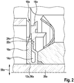
- FIG. 2 a section of one of the run-up elements 12a is shown in a sectional view.
- the first startup element 12a and the second startup element 12a are at least essentially identical.
- the first startup element 12a and the second startup element 12a are identical.
- the first starting element 12a has at least one cavity 14a for damping the at least one longitudinal armature vibration of the electric motor in at least one operating state.
- the second starting element 12a has a cavity 14a for damping the at least one longitudinal armature vibration of the electric motor in at least one operating state.
- the starting elements 12a each have a cavity 14a for damping the at least one longitudinal armature vibration of the electric motor in at least one operating state.
- the cavity 14a in each case forms a fluid cushion which is provided for damping the longitudinal armature vibration of the electric motor in an operating state.
- the cavity 14a in each case forms an air cushion in an assembled state.
- the cavity 14a forms a damping area of the respective starting element 12a.
- the cavity 14a is at least partially arranged along a circumferential direction 20a of the run-up elements 12a.
- the cavity 14a is arranged circumferentially along the circumferential direction 20a of the run-up elements 12a.
- the cavity 14a is each annular.
- the cavity 14a each has, in a plane that is perpendicular to a tangential direction of the run-up element 12a, two cross-sectional areas, each of which has a triangular area, a rectangular area and a semicircular area.
- the semicircular area, the rectangular area and the triangular area are arranged one after the other, viewed in the radial direction 58a of the starting element 12a from the inside out.
- the stop element 50a is formed in one piece with the first injection molding element 16a of the starting element 12a.
- the stop element 50a it is also conceivable for the stop element 50a to be adhesively bonded to the first injection molding element 16a of the starting element 12a or to be connected to the first injection molding element 16a of the starting element 12a in another manner which appears expedient to a person skilled in the art.
- the first starting element 12a and the second starting element 12a of the damping unit 10a each have a first injection molding element 16a and a second injection molding element 18a ( Figures 3a and 3b ).
- the first injection molding element 16a and the second injection molding element 18a are molded in succession in a 2-stage injection molding process.
- the first injection molding element 16a and the second injection molding element 18a are at least partially firmly connected to one another.
- the first injection molding element 16a and the second injection molding element 18a are each firmly connected to one another.
- the first injection molding element 16a and the second injection molding element 18a are at least partially made in one piece.
- the first injection molding element 16a and the second injection molding element 18a are each formed in one piece.
- the first injection molding element 16a is molded in a first step 60 of the injection molding process.
- the second injection molding element 18a is then shaped in a second step 62 of the injection molding process and molded onto the first injection molding element 16a.
- the second injection molding element 18a is formed separately in the second step 62 of the injection molding process and then connected to the first injection molding element 16a.
- the first startup element 12a and the second startup element 12a each have an ultrasound-processed contact region 22a, 24a between the first injection molding element 16a and the second injection molding element 18a ( Figure 7 ).
- the first injection molding element 16a has the contact area 22a.
- the second injection molding element 18a has the contact area 24a.
- the first startup element 12a and the second startup element 12a each have a high adhesion between the first injection molding element 16a and the second injection molding element 18a, so that the cohesive connection between them is released the first injection molding element 16a and the second injection molding element 18a of the starting element 12a can be prevented in an operating state of the damping unit 10a.
- the first injection molding element 16a and the second injection molding element 18a are at least partially formed from the same material.
- the first injection molding element 16a and the second injection molding element 18a are each formed entirely from the same material.
- the first injection molding element 16a and the second injection molding element 18a are formed from a plastic.
- the cavity 14a of the first startup element 12a and the cavity 14a of the second startup element 12a are each arranged at least essentially in the first injection molding element 16a or in the second injection molding element 18a ( Figure 4 ).
- the cavity 14a of the first startup element 12a is arranged in the first injection molding element 16a and is completely enclosed by the first injection molding element 16a.
- the cavity 14a of the second startup element 12a is arranged in the first injection molding element 16a and is completely enclosed by the first injection molding element 16a. However, it is also conceivable that the cavity 14a is arranged in the second injection molding element 18a and is enclosed by the second injection molding element 18a. In an assembled state, the cavity 14a of the first startup element 12a and the cavity 14a of the second startup element 12a are each at least substantially airtight. The cavity 14a of the first thrust element 12a and the cavity 14a of the second thrust element 12a are each airtight in an assembled state.
- the tab region 64a of the first injection molding element 16a is arranged at a distance from the contact region 22a of the first injection molding element 16a.
- the cavity 14a which is arranged in the first injection molding element 16a or in the second injection molding element 18a of the first starting element 12a or the second starting element 12a, is at least substantially closed.
- the cavity 14a which is introduced into the first injection molding element 16a, is closed. The cavity 14a is closed in the further method step 44 by pressing the tab area 64a onto the contact area 22a of the first injection molding element 16a.
- the second injection molding element 18a is injection molded onto the first injection molding element 16a.
- the tab region 64a of the first injection molding element 16a is fixed relative to the contact region 22a of the first injection molding element 16a in a closed state of the cavity 14a.
- the first starting element 12a and the second starting element 12a are each treated at least partially by means of an ultrasonic welding method.
- the first startup element 12a and the second startup element 12a are each treated in the contact area 22a, 24a between the first injection molding element 16a and the second injection molding element 18a by means of an ultrasonic welding method.
- other methods for improving adhesion between the first injection molding element 16a and the second injection molding element 18a which appear to be useful to a person skilled in the art, are also conceivable.
- a cohesive connection of the contact area 22a of the first injection molding element 16a and the contact area 24 of the second injection molding element 18a can thereby be improved.
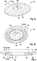
- a starting element 12b of a damping unit 10b according to the invention is shown.
- the starting element 12b largely corresponds to the already described starting element 12a.
- the damping unit 10b according to the invention has two starting elements 12b.
- the startup elements 12b are at least essentially identical.
- the start elements 12b are identical.
- the damping unit 10b according to the invention is produced in the method already described.
- the start-up element 12b comprises a first injection molding element 16b and a second injection molding element 18b.
- the first injection molding element 16b and the second injection molding element 18b are molded in succession in a 2-stage injection molding process.
- the first injection molding element 16b and the second injection molding element 18b are at least partially firmly connected to one another.
- the first injection molding element 16b and the second injection molding element 18b are each firmly connected to one another.
- the first injection molding element 16b and the second injection molding element 18b are at least partially integrally formed.
- the first injection molding element 16b and the second injection molding element 18b are each formed in one piece.
- the first injection molding element 16b is attached to the second injection molding element 18b in the injection molding process molded.
- the first injection molding element 16b and the second injection molding element 18b are integrally connected to one another.
- the starting element 12b comprises at least one toothing element 26b, which is provided at least partially for a form-fitting coupling between the at least one first injection molding element 16b and the at least one second injection molding element 18b.
- the starting element 12b comprises at least two toothing elements 26b.
- the starting element 12b comprises a plurality of toothing elements 26b, which are provided for an additional positive coupling between the first injection molding element 16b and the second injection molding element 18b.
- the toothing elements 26b are arranged distributed uniformly in the circumferential direction 20b of the starting element 12b.
- the start-up element 12b has eight toothed elements 26b arranged uniformly distributed in the circumferential direction 20b.
- the toothing elements 26b of the second injection molding element are injection molded onto the first injection molding element 16b in a plane which is arranged parallel to a circumferential direction 20b of the start-up element 12b and fix the first injection molding element 16b in a cohesive manner.
- the toothing elements 26b of the second injection molding element overlap the first injection molding element 16b in a plane which is arranged parallel to a circumferential direction 20b of the starting element 12b and fix the first injection molding element 16b in a form-fitting manner.
Landscapes
- Engineering & Computer Science (AREA)
- General Engineering & Computer Science (AREA)
- Power Engineering (AREA)
- Mechanical Engineering (AREA)
- Injection Moulding Of Plastics Or The Like (AREA)
- Motor Or Generator Frames (AREA)
Applications Claiming Priority (2)
| Application Number | Priority Date | Filing Date | Title |
|---|---|---|---|
| DE102014102134.7A DE102014102134A1 (de) | 2014-02-19 | 2014-02-19 | Dämpfungseinheit |
| PCT/EP2014/078535 WO2015124238A1 (de) | 2014-02-19 | 2014-12-18 | Dämpfungseinheit |
Publications (2)
| Publication Number | Publication Date |
|---|---|
| EP3108573A1 EP3108573A1 (de) | 2016-12-28 |
| EP3108573B1 true EP3108573B1 (de) | 2020-02-26 |
Family
ID=52146490
Family Applications (1)
| Application Number | Title | Priority Date | Filing Date |
|---|---|---|---|
| EP14818974.9A Active EP3108573B1 (de) | 2014-02-19 | 2014-12-18 | Dämpfungseinheit |
Country Status (8)
| Country | Link |
|---|---|
| US (1) | US20170018990A1 (enExample) |
| EP (1) | EP3108573B1 (enExample) |
| JP (1) | JP2017517233A (enExample) |
| KR (1) | KR20160138010A (enExample) |
| CN (1) | CN106030999B (enExample) |
| BR (1) | BR112016018677B1 (enExample) |
| DE (1) | DE102014102134A1 (enExample) |
| WO (1) | WO2015124238A1 (enExample) |
Families Citing this family (2)
| Publication number | Priority date | Publication date | Assignee | Title |
|---|---|---|---|---|
| WO2018036980A1 (de) * | 2016-08-26 | 2018-03-01 | Ebm-Papst St. Georgen Gmbh & Co. Kg | Vorrichtung, insbesondere lüftervorrichtung, und verfahren zur dämpfung einer vorrichtung, insbesondere lüftervorrichtung |
| CN107612184B (zh) * | 2017-10-19 | 2024-02-20 | 广州市瑞宝电器有限公司 | 一种一体式电机端盖及其精加工方法 |
Family Cites Families (10)
| Publication number | Priority date | Publication date | Assignee | Title |
|---|---|---|---|---|
| US3573510A (en) * | 1969-06-09 | 1971-04-06 | Gen Electric | Cushion thrust washer |
| JPS5226106U (enExample) * | 1975-08-14 | 1977-02-23 | ||
| JPS53149805U (enExample) * | 1977-04-30 | 1978-11-25 | ||
| DE3145601C3 (de) * | 1981-11-17 | 1992-08-06 | Mulfingen Elektrobau Ebm | Anlaufscheibe |
| DE59400475D1 (de) * | 1994-08-24 | 1996-09-05 | Siemens Ag | Anlauf- bzw. Abdeckscheibe für ein Lager auf einer Rotorwelle |
| US5945756A (en) * | 1997-10-07 | 1999-08-31 | Siemens Canada Limited | Ultra quiet electric motor for automotive applications |
| US6376952B1 (en) * | 1999-07-14 | 2002-04-23 | E. I. Du Pont De Nemours And Company | Bearing system for a rotating shaft |
| DE102008062432A1 (de) * | 2008-12-17 | 2010-07-15 | Brose Fahrzeugteile GmbH & Co. Kommanditgesellschaft, Würzburg | Elektromotorischer Antrieb, insbesondere Gebläseantrieb |
| DE102011076081A1 (de) * | 2011-05-18 | 2012-11-22 | Robert Bosch Gmbh | Anlaufscheibe für eine elektrische Maschine |
| DE102011090062A1 (de) * | 2011-05-18 | 2012-11-22 | Robert Bosch Gmbh | Anlaufscheibe für eine elektrische Maschine |
-
2014
- 2014-02-19 DE DE102014102134.7A patent/DE102014102134A1/de not_active Withdrawn
- 2014-12-18 BR BR112016018677-0A patent/BR112016018677B1/pt active IP Right Grant
- 2014-12-18 WO PCT/EP2014/078535 patent/WO2015124238A1/de not_active Ceased
- 2014-12-18 US US15/119,159 patent/US20170018990A1/en not_active Abandoned
- 2014-12-18 CN CN201480075806.5A patent/CN106030999B/zh active Active
- 2014-12-18 JP JP2016548347A patent/JP2017517233A/ja not_active Ceased
- 2014-12-18 KR KR1020167025529A patent/KR20160138010A/ko not_active Ceased
- 2014-12-18 EP EP14818974.9A patent/EP3108573B1/de active Active
Non-Patent Citations (1)
| Title |
|---|
| None * |
Also Published As
| Publication number | Publication date |
|---|---|
| CN106030999A (zh) | 2016-10-12 |
| BR112016018677B1 (pt) | 2022-01-04 |
| DE102014102134A1 (de) | 2015-08-20 |
| KR20160138010A (ko) | 2016-12-02 |
| JP2017517233A (ja) | 2017-06-22 |
| WO2015124238A1 (de) | 2015-08-27 |
| CN106030999B (zh) | 2020-03-10 |
| US20170018990A1 (en) | 2017-01-19 |
| BR112016018677A2 (enExample) | 2017-08-08 |
| EP3108573A1 (de) | 2016-12-28 |
Similar Documents
| Publication | Publication Date | Title |
|---|---|---|
| DE69938287T2 (de) | Rotoranordnung für einen bürstenlosen Motor der Aussenläuferbauart | |
| DE102010019502B4 (de) | Pumpe mit integriertem elektronisch kommutierten Gleichstrommotor | |
| DE102008054037B4 (de) | Geräuscharme Kreiselpumpe | |
| EP2398130A2 (de) | Elektrokleinmotor | |
| EP1636892A1 (de) | Entkopplungsvorrichtung für elektromotoren und verfahren zur herstellung eines elektromotors | |
| DE102004007322A1 (de) | Statoranordnung für eine elektrische Maschine | |
| DE102007063307A1 (de) | Montageverfahren zum Einpassen eines Permanentmagneten in ein Halteelement | |
| DE102017103619A1 (de) | Elektromotor, Innenrotor und Rotorblech | |
| DE102014212566A1 (de) | Elektromotor-Baukasten und Elektromotor | |
| DE102009047485A1 (de) | Elektrische Maschine | |
| DE112014002427T5 (de) | Generatorlüfter | |
| EP3108573B1 (de) | Dämpfungseinheit | |
| DE102022207108A1 (de) | Elektrische Maschine mit einem Motorgehäuse und einem Kundenanschluss-Flansch | |
| DE102009023080A1 (de) | Elektrische Maschine | |
| DE102009003228A1 (de) | Elektrische Maschine | |
| DE102007032138A1 (de) | Rotor für eine elektrische Maschine sowie Verfahren zur Befestigung von Lamellen- oder Rotorblechpaketen auf einer Rotorwelle oder einem Rotorträger eines Rotors | |
| DE102013217077A1 (de) | Bürsteneinrichtung für eine elektrische Maschine und elektrische Maschine | |
| DE112014006868T5 (de) | Motorabdeckung | |
| WO2012028407A1 (de) | Oszillationseinsatzwerkzeug und lochsägeeinsatzwerkzeug | |
| EP2710711B1 (de) | Anlaufscheibe für eine elektrische maschine | |
| EP1617085B1 (de) | Gedämpfter Lüfter | |
| EP2144350A2 (de) | Rotor für einen Elektromotor sowie Verfahren zu seiner Herstellung | |
| DE10328800A1 (de) | Vorrichtung, insbesondere elektrische Maschine, mit über einen Presssitz miteinander verbundenen Bauteilen | |
| DE102014216743B4 (de) | Elektrische Maschine | |
| WO2013010757A2 (de) | Ringelement für einen läufer eines elektromotors |
Legal Events
| Date | Code | Title | Description |
|---|---|---|---|
| PUAI | Public reference made under article 153(3) epc to a published international application that has entered the european phase |
Free format text: ORIGINAL CODE: 0009012 |
|
| STAA | Information on the status of an ep patent application or granted ep patent |
Free format text: STATUS: REQUEST FOR EXAMINATION WAS MADE |
|
| 17P | Request for examination filed |
Effective date: 20160819 |
|
| AK | Designated contracting states |
Kind code of ref document: A1 Designated state(s): AL AT BE BG CH CY CZ DE DK EE ES FI FR GB GR HR HU IE IS IT LI LT LU LV MC MK MT NL NO PL PT RO RS SE SI SK SM TR |
|
| AX | Request for extension of the european patent |
Extension state: BA ME |
|
| DAX | Request for extension of the european patent (deleted) | ||
| REG | Reference to a national code |
Ref country code: DE Ref legal event code: R079 Ref document number: 502014013715 Country of ref document: DE Free format text: PREVIOUS MAIN CLASS: H02K0005240000 Ipc: F16C0027020000 |
|
| RIC1 | Information provided on ipc code assigned before grant |
Ipc: F16C 27/02 20060101AFI20180709BHEP Ipc: F16C 27/08 20060101ALI20180709BHEP Ipc: H02K 5/24 20060101ALI20180709BHEP Ipc: H02K 5/16 20060101ALI20180709BHEP Ipc: H02K 5/167 20060101ALI20180709BHEP |
|
| GRAP | Despatch of communication of intention to grant a patent |
Free format text: ORIGINAL CODE: EPIDOSNIGR1 |
|
| STAA | Information on the status of an ep patent application or granted ep patent |
Free format text: STATUS: GRANT OF PATENT IS INTENDED |
|
| INTG | Intention to grant announced |
Effective date: 20180910 |
|
| GRAJ | Information related to disapproval of communication of intention to grant by the applicant or resumption of examination proceedings by the epo deleted |
Free format text: ORIGINAL CODE: EPIDOSDIGR1 |
|
| STAA | Information on the status of an ep patent application or granted ep patent |
Free format text: STATUS: REQUEST FOR EXAMINATION WAS MADE |
|
| STAA | Information on the status of an ep patent application or granted ep patent |
Free format text: STATUS: EXAMINATION IS IN PROGRESS |
|
| INTC | Intention to grant announced (deleted) | ||
| 17Q | First examination report despatched |
Effective date: 20181210 |
|
| RAP1 | Party data changed (applicant data changed or rights of an application transferred) |
Owner name: ROBERT BOSCH GMBH |
|
| GRAP | Despatch of communication of intention to grant a patent |
Free format text: ORIGINAL CODE: EPIDOSNIGR1 |
|
| STAA | Information on the status of an ep patent application or granted ep patent |
Free format text: STATUS: GRANT OF PATENT IS INTENDED |
|
| INTG | Intention to grant announced |
Effective date: 20191016 |
|
| GRAS | Grant fee paid |
Free format text: ORIGINAL CODE: EPIDOSNIGR3 |
|
| GRAA | (expected) grant |
Free format text: ORIGINAL CODE: 0009210 |
|
| STAA | Information on the status of an ep patent application or granted ep patent |
Free format text: STATUS: THE PATENT HAS BEEN GRANTED |
|
| AK | Designated contracting states |
Kind code of ref document: B1 Designated state(s): AL AT BE BG CH CY CZ DE DK EE ES FI FR GB GR HR HU IE IS IT LI LT LU LV MC MK MT NL NO PL PT RO RS SE SI SK SM TR |
|
| REG | Reference to a national code |
Ref country code: GB Ref legal event code: FG4D Free format text: NOT ENGLISH |
|
| REG | Reference to a national code |
Ref country code: CH Ref legal event code: EP |
|
| REG | Reference to a national code |
Ref country code: AT Ref legal event code: REF Ref document number: 1237976 Country of ref document: AT Kind code of ref document: T Effective date: 20200315 |
|
| REG | Reference to a national code |
Ref country code: IE Ref legal event code: FG4D Free format text: LANGUAGE OF EP DOCUMENT: GERMAN |
|
| REG | Reference to a national code |
Ref country code: DE Ref legal event code: R096 Ref document number: 502014013715 Country of ref document: DE |
|
| RAP2 | Party data changed (patent owner data changed or rights of a patent transferred) |
Owner name: ROBERT BOSCH GMBH |
|
| PG25 | Lapsed in a contracting state [announced via postgrant information from national office to epo] |
Ref country code: NO Free format text: LAPSE BECAUSE OF FAILURE TO SUBMIT A TRANSLATION OF THE DESCRIPTION OR TO PAY THE FEE WITHIN THE PRESCRIBED TIME-LIMIT Effective date: 20200526 Ref country code: FI Free format text: LAPSE BECAUSE OF FAILURE TO SUBMIT A TRANSLATION OF THE DESCRIPTION OR TO PAY THE FEE WITHIN THE PRESCRIBED TIME-LIMIT Effective date: 20200226 Ref country code: RS Free format text: LAPSE BECAUSE OF FAILURE TO SUBMIT A TRANSLATION OF THE DESCRIPTION OR TO PAY THE FEE WITHIN THE PRESCRIBED TIME-LIMIT Effective date: 20200226 |
|
| REG | Reference to a national code |
Ref country code: NL Ref legal event code: MP Effective date: 20200226 |
|
| REG | Reference to a national code |
Ref country code: LT Ref legal event code: MG4D |
|
| PG25 | Lapsed in a contracting state [announced via postgrant information from national office to epo] |
Ref country code: HR Free format text: LAPSE BECAUSE OF FAILURE TO SUBMIT A TRANSLATION OF THE DESCRIPTION OR TO PAY THE FEE WITHIN THE PRESCRIBED TIME-LIMIT Effective date: 20200226 Ref country code: GR Free format text: LAPSE BECAUSE OF FAILURE TO SUBMIT A TRANSLATION OF THE DESCRIPTION OR TO PAY THE FEE WITHIN THE PRESCRIBED TIME-LIMIT Effective date: 20200527 Ref country code: IS Free format text: LAPSE BECAUSE OF FAILURE TO SUBMIT A TRANSLATION OF THE DESCRIPTION OR TO PAY THE FEE WITHIN THE PRESCRIBED TIME-LIMIT Effective date: 20200626 Ref country code: BG Free format text: LAPSE BECAUSE OF FAILURE TO SUBMIT A TRANSLATION OF THE DESCRIPTION OR TO PAY THE FEE WITHIN THE PRESCRIBED TIME-LIMIT Effective date: 20200526 Ref country code: LV Free format text: LAPSE BECAUSE OF FAILURE TO SUBMIT A TRANSLATION OF THE DESCRIPTION OR TO PAY THE FEE WITHIN THE PRESCRIBED TIME-LIMIT Effective date: 20200226 Ref country code: SE Free format text: LAPSE BECAUSE OF FAILURE TO SUBMIT A TRANSLATION OF THE DESCRIPTION OR TO PAY THE FEE WITHIN THE PRESCRIBED TIME-LIMIT Effective date: 20200226 |
|
| PG25 | Lapsed in a contracting state [announced via postgrant information from national office to epo] |
Ref country code: NL Free format text: LAPSE BECAUSE OF FAILURE TO SUBMIT A TRANSLATION OF THE DESCRIPTION OR TO PAY THE FEE WITHIN THE PRESCRIBED TIME-LIMIT Effective date: 20200226 |
|
| PG25 | Lapsed in a contracting state [announced via postgrant information from national office to epo] |
Ref country code: CZ Free format text: LAPSE BECAUSE OF FAILURE TO SUBMIT A TRANSLATION OF THE DESCRIPTION OR TO PAY THE FEE WITHIN THE PRESCRIBED TIME-LIMIT Effective date: 20200226 Ref country code: RO Free format text: LAPSE BECAUSE OF FAILURE TO SUBMIT A TRANSLATION OF THE DESCRIPTION OR TO PAY THE FEE WITHIN THE PRESCRIBED TIME-LIMIT Effective date: 20200226 Ref country code: PT Free format text: LAPSE BECAUSE OF FAILURE TO SUBMIT A TRANSLATION OF THE DESCRIPTION OR TO PAY THE FEE WITHIN THE PRESCRIBED TIME-LIMIT Effective date: 20200719 Ref country code: LT Free format text: LAPSE BECAUSE OF FAILURE TO SUBMIT A TRANSLATION OF THE DESCRIPTION OR TO PAY THE FEE WITHIN THE PRESCRIBED TIME-LIMIT Effective date: 20200226 Ref country code: ES Free format text: LAPSE BECAUSE OF FAILURE TO SUBMIT A TRANSLATION OF THE DESCRIPTION OR TO PAY THE FEE WITHIN THE PRESCRIBED TIME-LIMIT Effective date: 20200226 Ref country code: DK Free format text: LAPSE BECAUSE OF FAILURE TO SUBMIT A TRANSLATION OF THE DESCRIPTION OR TO PAY THE FEE WITHIN THE PRESCRIBED TIME-LIMIT Effective date: 20200226 Ref country code: EE Free format text: LAPSE BECAUSE OF FAILURE TO SUBMIT A TRANSLATION OF THE DESCRIPTION OR TO PAY THE FEE WITHIN THE PRESCRIBED TIME-LIMIT Effective date: 20200226 Ref country code: SM Free format text: LAPSE BECAUSE OF FAILURE TO SUBMIT A TRANSLATION OF THE DESCRIPTION OR TO PAY THE FEE WITHIN THE PRESCRIBED TIME-LIMIT Effective date: 20200226 Ref country code: SK Free format text: LAPSE BECAUSE OF FAILURE TO SUBMIT A TRANSLATION OF THE DESCRIPTION OR TO PAY THE FEE WITHIN THE PRESCRIBED TIME-LIMIT Effective date: 20200226 |
|
| REG | Reference to a national code |
Ref country code: DE Ref legal event code: R097 Ref document number: 502014013715 Country of ref document: DE |
|
| PLBE | No opposition filed within time limit |
Free format text: ORIGINAL CODE: 0009261 |
|
| STAA | Information on the status of an ep patent application or granted ep patent |
Free format text: STATUS: NO OPPOSITION FILED WITHIN TIME LIMIT |
|
| PG25 | Lapsed in a contracting state [announced via postgrant information from national office to epo] |
Ref country code: IT Free format text: LAPSE BECAUSE OF FAILURE TO SUBMIT A TRANSLATION OF THE DESCRIPTION OR TO PAY THE FEE WITHIN THE PRESCRIBED TIME-LIMIT Effective date: 20200226 |
|
| 26N | No opposition filed |
Effective date: 20201127 |
|
| PG25 | Lapsed in a contracting state [announced via postgrant information from national office to epo] |
Ref country code: PL Free format text: LAPSE BECAUSE OF FAILURE TO SUBMIT A TRANSLATION OF THE DESCRIPTION OR TO PAY THE FEE WITHIN THE PRESCRIBED TIME-LIMIT Effective date: 20200226 Ref country code: SI Free format text: LAPSE BECAUSE OF FAILURE TO SUBMIT A TRANSLATION OF THE DESCRIPTION OR TO PAY THE FEE WITHIN THE PRESCRIBED TIME-LIMIT Effective date: 20200226 |
|
| REG | Reference to a national code |
Ref country code: CH Ref legal event code: PL |
|
| GBPC | Gb: european patent ceased through non-payment of renewal fee |
Effective date: 20201218 |
|
| PG25 | Lapsed in a contracting state [announced via postgrant information from national office to epo] |
Ref country code: MC Free format text: LAPSE BECAUSE OF FAILURE TO SUBMIT A TRANSLATION OF THE DESCRIPTION OR TO PAY THE FEE WITHIN THE PRESCRIBED TIME-LIMIT Effective date: 20200226 |
|
| REG | Reference to a national code |
Ref country code: BE Ref legal event code: MM Effective date: 20201231 |
|
| PG25 | Lapsed in a contracting state [announced via postgrant information from national office to epo] |
Ref country code: LU Free format text: LAPSE BECAUSE OF NON-PAYMENT OF DUE FEES Effective date: 20201218 Ref country code: IE Free format text: LAPSE BECAUSE OF NON-PAYMENT OF DUE FEES Effective date: 20201218 |
|
| PG25 | Lapsed in a contracting state [announced via postgrant information from national office to epo] |
Ref country code: LI Free format text: LAPSE BECAUSE OF NON-PAYMENT OF DUE FEES Effective date: 20201231 Ref country code: CH Free format text: LAPSE BECAUSE OF NON-PAYMENT OF DUE FEES Effective date: 20201231 Ref country code: GB Free format text: LAPSE BECAUSE OF NON-PAYMENT OF DUE FEES Effective date: 20201218 |
|
| REG | Reference to a national code |
Ref country code: AT Ref legal event code: MM01 Ref document number: 1237976 Country of ref document: AT Kind code of ref document: T Effective date: 20201218 |
|
| PG25 | Lapsed in a contracting state [announced via postgrant information from national office to epo] |
Ref country code: AT Free format text: LAPSE BECAUSE OF NON-PAYMENT OF DUE FEES Effective date: 20201218 |
|
| PG25 | Lapsed in a contracting state [announced via postgrant information from national office to epo] |
Ref country code: TR Free format text: LAPSE BECAUSE OF FAILURE TO SUBMIT A TRANSLATION OF THE DESCRIPTION OR TO PAY THE FEE WITHIN THE PRESCRIBED TIME-LIMIT Effective date: 20200226 Ref country code: MT Free format text: LAPSE BECAUSE OF FAILURE TO SUBMIT A TRANSLATION OF THE DESCRIPTION OR TO PAY THE FEE WITHIN THE PRESCRIBED TIME-LIMIT Effective date: 20200226 Ref country code: CY Free format text: LAPSE BECAUSE OF FAILURE TO SUBMIT A TRANSLATION OF THE DESCRIPTION OR TO PAY THE FEE WITHIN THE PRESCRIBED TIME-LIMIT Effective date: 20200226 |
|
| PG25 | Lapsed in a contracting state [announced via postgrant information from national office to epo] |
Ref country code: MK Free format text: LAPSE BECAUSE OF FAILURE TO SUBMIT A TRANSLATION OF THE DESCRIPTION OR TO PAY THE FEE WITHIN THE PRESCRIBED TIME-LIMIT Effective date: 20200226 Ref country code: AL Free format text: LAPSE BECAUSE OF FAILURE TO SUBMIT A TRANSLATION OF THE DESCRIPTION OR TO PAY THE FEE WITHIN THE PRESCRIBED TIME-LIMIT Effective date: 20200226 |
|
| PG25 | Lapsed in a contracting state [announced via postgrant information from national office to epo] |
Ref country code: BE Free format text: LAPSE BECAUSE OF NON-PAYMENT OF DUE FEES Effective date: 20201231 |
|
| PGFP | Annual fee paid to national office [announced via postgrant information from national office to epo] |
Ref country code: DE Payment date: 20240227 Year of fee payment: 10 |
|
| PGFP | Annual fee paid to national office [announced via postgrant information from national office to epo] |
Ref country code: FR Payment date: 20241217 Year of fee payment: 11 |
|
| REG | Reference to a national code |
Ref country code: DE Ref legal event code: R119 Ref document number: 502014013715 Country of ref document: DE |
|
| PG25 | Lapsed in a contracting state [announced via postgrant information from national office to epo] |
Ref country code: DE Free format text: LAPSE BECAUSE OF NON-PAYMENT OF DUE FEES Effective date: 20250701 |