EP3108471B1 - Strip to be printed, comprising a protective film or protective coating - Google Patents
Strip to be printed, comprising a protective film or protective coating Download PDFInfo
- Publication number
- EP3108471B1 EP3108471B1 EP15706407.2A EP15706407A EP3108471B1 EP 3108471 B1 EP3108471 B1 EP 3108471B1 EP 15706407 A EP15706407 A EP 15706407A EP 3108471 B1 EP3108471 B1 EP 3108471B1
- Authority
- EP
- European Patent Office
- Prior art keywords
- strip
- adhesive
- sheet
- film
- free
- Prior art date
- Legal status (The legal status is an assumption and is not a legal conclusion. Google has not performed a legal analysis and makes no representation as to the accuracy of the status listed.)
- Active
Links
Images


Classifications
-
- B—PERFORMING OPERATIONS; TRANSPORTING
- B41—PRINTING; LINING MACHINES; TYPEWRITERS; STAMPS
- B41J—TYPEWRITERS; SELECTIVE PRINTING MECHANISMS, i.e. MECHANISMS PRINTING OTHERWISE THAN FROM A FORME; CORRECTION OF TYPOGRAPHICAL ERRORS
- B41J11/00—Devices or arrangements of selective printing mechanisms, e.g. ink-jet printers or thermal printers, for supporting or handling copy material in sheet or web form
- B41J11/36—Blanking or long feeds; Feeding to a particular line, e.g. by rotation of platen or feed roller
- B41J11/42—Controlling printing material conveyance for accurate alignment of the printing material with the printhead; Print registering
- B41J11/46—Controlling printing material conveyance for accurate alignment of the printing material with the printhead; Print registering by marks or formations on the paper being fed
-
- B—PERFORMING OPERATIONS; TRANSPORTING
- B41—PRINTING; LINING MACHINES; TYPEWRITERS; STAMPS
- B41J—TYPEWRITERS; SELECTIVE PRINTING MECHANISMS, i.e. MECHANISMS PRINTING OTHERWISE THAN FROM A FORME; CORRECTION OF TYPOGRAPHICAL ERRORS
- B41J3/00—Typewriters or selective printing or marking mechanisms characterised by the purpose for which they are constructed
- B41J3/407—Typewriters or selective printing or marking mechanisms characterised by the purpose for which they are constructed for marking on special material
- B41J3/4075—Tape printers; Label printers
-
- B—PERFORMING OPERATIONS; TRANSPORTING
- B41—PRINTING; LINING MACHINES; TYPEWRITERS; STAMPS
- B41J—TYPEWRITERS; SELECTIVE PRINTING MECHANISMS, i.e. MECHANISMS PRINTING OTHERWISE THAN FROM A FORME; CORRECTION OF TYPOGRAPHICAL ERRORS
- B41J11/00—Devices or arrangements of selective printing mechanisms, e.g. ink-jet printers or thermal printers, for supporting or handling copy material in sheet or web form
- B41J11/66—Applications of cutting devices
Definitions
- the present invention relates to a tape or sheet for printing by means of a printer, the tape or sheet being printable on one flat side and having an adhesive or adhesive layer on its other flat side, which areas are adhesive-free or adhesive-free and adhesive or adhesive Has areas that are spaced apart at least in the longitudinal direction of the tape or sheet.
- WO 2012/167806 A1 known tape on its flat side facing away from the printable flat side has an adhesive or adhesive layer which has adhesive-free or adhesive-free areas and adhesive or adhesive areas which are at least in the longitudinal direction of the tape from one another are spaced.
- the printer has a sensor device by means of which the adhesive-free or adhesive-free areas can be detected, so that the tape feed device can always position the tape for cutting in such a way that the cutting knife only cuts the tape in the adhesive-free or adhesive-free area and it this advantageously prevents the cutting unit from sticking together.
- WO 2012/167806 A1 Known tape is that the printable flat side must be coated with a non-stick or anti-adhesive layer, for example in the form of a silicone layer, so that the tape can be rolled up.
- printable tapes which have an adhesive layer which is arranged on the printable side, the tapes having an additional peelable film by means of which the adhesive layer is covered, so that the tape can be rolled up.
- the object of the present invention is to provide a printable tape with an adhesive layer and a film covering and peeling it off, in which the non-adhesive areas are easily recognizable.
- the film is characterized, inter alia, in that the adhesive or adhesive layer is covered by a peelable film, a peelable or dissolvable coating.
- the film is also cut when the tape is cut or cut. Both the ribbon remaining in the printer and the printed cut-off tape section is further protected by the film and undesired sticking or adhering is advantageously prevented. If the printed and cut tape area is to be glued to a surface or an object, the film or the coating can be pulled off or removed from the tape, as a result of which the adhesive or adhesive layer is exposed and gluing or adhering is possible.
- the tape according to the invention can be cut through the adhesive-free or adhesive-free areas, so that the cutting edges of the printer do not stick together. As a result, the printer has to be serviced and cleaned much less frequently, which greatly reduces the TCO.
- the tape or sheet according to the invention for producing stamps. Due to the lack of silicone coating on the printable side, the stamp produced from the tape or sheet according to the invention can be canceled by means of a stamp, which would not be possible with a silicone coating, since the stamp ink can be wiped off the silicone coating.
- the tape or sheet according to the invention can in principle be made of any printable material, in particular paper, such as Thermal paper or thermal transfer paper, or cardboard.
- the tape or sheet can also have a carrier film, one flat side of which has the adhesive or adhesive layer with the adhesive-free or adhesive-free areas, which in turn is covered with the peelable film or coating.
- the carrier film itself can also have a multilayer structure. It only has to be ensured that the printable page also with e.g. Stamp ink or fountain pen inks or other printing or staining is writable.
- the long sides of the tape are not straight, but have serrations like conventional stamps.
- the edge regions of the long sides can likewise have no adhesive layer or adhesive layer, so that when the tape is rolled up, as already in FIG WO2012 / 167806 A1 described, no adhesive escapes from the side or the tape roll does not stick to the side.
- the tape or sheet according to the invention additionally has continuous adhesive-free or adhesive-free strips extending in the longitudinal direction of the tape or sheet, so that the tape or sheet can also be cut through in the longitudinal direction.
- the tape or sheet can advantageously be perforated in the area of the adhesive-free or adhesive-free areas and strips, so that it can be torn apart into smaller parts by hand or by machine.
- the perforation can of course also be produced by means of the printer, the perforation device of the printer being controllable and thus the perforation being able to be produced as required and at different locations on the band or sheet.
- coherent stamps or labels can be printed by means of the tape or sheet according to the invention, which can only be easily separated by hand and at the intended location or locations if required.
- the tape can be rolled up on a roll.
- the length of the printable area in the longitudinal direction of the tape can advantageously be freely determined. All that is required is a cutting device or a tear-off device in order to separate the printed tape from the tape that has not yet been printed.
- the tape is advantageously cut only where there is no adhesive or adhesive layer.
- the adhesive or adhesive layer is covered by at least two foil tapes which extend in the tape longitudinal direction and which are arranged next to one another in the tape longitudinal direction. It is preferable if the tape has only two film tapes that either adjoin one another or overlap slightly. By using at least two, advantageously exactly two, foil tapes, these can easily be detached from the printed tape, for example by bending the tape from the adhesive / adhesive layer.
- the Figure 1 shows a plan view of the underside of the coated with adhesive WO 2012/167806 A1 known tape 1, the adhesive being applied in strip form by means of transverse strips 2 to the tape.
- Adhesive-free transverse strips 3 are located between the adhesive strips 2, in the areas of which the strip can be severed by means of a cutting device of a printer.
- the dashed line S indicates the possible placement of a cutting device.
- the tape is transported in the longitudinal direction L by means of a transport device.
- the transport device serves to position the belt 1 over the cutting device S.
- the belt has an end face 7 and long sides 6.
- To the right of the tape is an enlarged detail of the tape with its adhesive strips 2.
- the adhesive-free strips 3 are arranged between the adhesive strips 2, the adhesive strips 2 having a width 4 and the adhesive-free regions having a width 5.
- the widths 4, 5 can be chosen arbitrarily. In principle, however, it makes sense that the width 5 is chosen to be as small as possible so that the tape 1 adheres as well as possible.
- the width 5 depends crucially on the dimensioning of the cutting device. This means that it must be ensured that the width 5 is chosen so large that no adhesive or adhesive material contaminates the cutting edges of the cutting device during the cutting process.
- the width 4 of the adhesive strips 2 should also be made as small as possible so that the tape can be cut at points as close as possible to one another. This ensures that the tape is used in the best possible way can be.
- the adhesive strips 2 have a greater width 4 than the non-adhesive areas 5.
- FIG 2 is a second possible education from WO 2012/167806 A1 known tape 1 shown, in which the width of an adhesive strip 2 is equal to the width of the non-adhesive areas.
- the edge regions 8 of the tape 1 are designed to be adhesive-free, so that it is ensured that no adhesive escapes from the lateral areas of the wound tape 1.
- the edge areas 8 should be made as narrow as possible so that the edge 6 of the glued receipt or label cannot stand out.
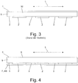
- the Figure 3 shows a cross section through the WO 2012/167806 A1 Known tape 1.
- the tape 1 has a backing layer 9, which on its one side, which is in particular the printing side, has a silicone layer 10, so that this side does not stick to the rolled-up tape 1 with the adhesive strips 2 of the tape 1.
- the adhesive strips 2 are arranged at a distance from one another in the longitudinal direction 2 and form the non-adhesive areas 3 between them.
- the Figure 5 shows a further possible embodiment of the tape 1 according to the invention which, in addition to the adhesive-free areas 3 running transversely to the longitudinal direction L of the tape 1, also has adhesive-free strip-shaped areas LS extending in the longitudinal direction.
- the printed tape can be made out by means of a WO 2012/167806 A1 known cutting device of a printer can be cut.
- the printed tape can also be cut by hand using scissors.
- perforations extending in the longitudinal direction L are incorporated in the region of the adhesive-free strip-shaped regions LS or can be incorporated by means of a printer.
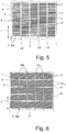
- FIG. 6 A further possible embodiment of a band 1 according to the invention is shown which has perforation regions PFL which extend in the longitudinal direction L and which are spaced apart from one another.
- perforation areas PF Q which extend transversely to the longitudinal direction L are present at regular intervals from one another.
- the perforation areas PF L , PF Q can be covered by the adhesive 2 or adhesive.
- the tape 1 it is also possible for the tape 1 to be adhesive-free or adhesive-free in the area of the perforation areas PF L , PF Q.
- the perforation areas PF L , PF Q can either be prefabricated or, if required, can be worked into the belt at any or predetermined locations by the printer.
- the Figure 7 shows a plan view of the side coated with adhesive of a printable tape 1 according to the invention with laterally arranged markings M.
- the markings M are in the area of the one adhesive-free area 8 along the long side 6 for recognizing the adhesive-free or adhesive-free areas 2 and / or with Adhesive or adhesive coated areas 2 applied or incorporated. Of course, the markings can also be arranged on both sides in both adhesive-free areas 8.
- the markings M can be printed symbols, in particular in the form of lines, rectangles or dots, and are formed by punched-outs in the form of holes.
- the markings M are arranged in the longitudinal direction L of the strip 1 at, in particular, regular intervals from one another.
- the printer recognizes the markings M through the in particular transparent and peelable film F or the coating AB and, based on the knowledge of the positioning of the markings relative to the areas 2, 3, the tape 1 or the sheet 1 'relative to the Print head and / or to the cutting unit and / or to the perforation device position so that printing, cutting and / or perforating is done in the right places.
- the markings M may be applied or incorporated on the removable film F. It is also possible that the markings M e.g. are made of magnetic material so that a Hall sensor can be used as the sensor.
- the Figure 8 shows a cross-sectional view through a tape 1 according to the invention, which has a printable layer 9, on the side facing away from the printable side 1, the adhesive or adhesive layer 2 is arranged.
- the adhesive or adhesive layer 2 is covered by the film F, so that the tape 1 cannot inadvertently adhere or stick to an object with its adhesive or adhesive layer 2. So that the film F can be removed more easily from the adhesive or adhesive layer 2 of the tape 1, the film F extends at least with its one long side F sl and / or F sr over the long side 9s of the printable layer 9.
- the adhesive or adhesive layer of the tape 1 as in the Figures 9a to 9c shown, be covered by means of two foil strips F 1 and F 2 .
- the two film strips F 1 and F 2 can adjoin each other with their mutually facing longitudinal sides F 1s and F 2s or, as in FIGS Figures 9a to 9c shown to be spaced apart by a gap Sp.
- the width of the gap Sp extending in the longitudinal direction L can be chosen to be as small as desired. For example, it is possible first to apply or apply a single film, which extends over the entire width of the printable layer, to the adhesive or adhesive layer 2, in order to then subsequently use a knife or another separating device to film the film in the longitudinal direction L of the tape 1 to share.
- the tape can be bent by applying bending or kinking forces BK, whereby at least one long side F 1s of a film tape F 1 extends from the underside 2u of the adhesive or adhesive layer 2 at least in some areas dissolves so that this film can be easily removed from the printable layer 9 or its adhesive layer 2.
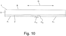
- the Figure 10 shows a cross-sectional view through an alternative embodiment in which the two foil bands F 1 and F 2 with their longitudinal sides F 1s and F 2s overlap, wherein the longitudinal side F 2s of the film strip F 2 adhered to the adhesive or adhesive layer 2 and is liable and the long side F 1s of the film strip F 1 rests on the long side F 2s and overlaps it without adhering to or sticking to it.
- the long side F 1s of the film strip F 1 can be easily gripped, as a result of which the film strip F 1 is easy to pull off.
- the film strip F 2 can then by bending or bending, as in Figure 9c is shown, are detached from the adhesive or adhesive layer 2.
- the printable layer 9 extends continuously in the longitudinal direction L of the tape 1 or sheet 1 ', so that the tape 1 or sheet 1' can be printed continuously over its entire length.
- the printable layer 9 can, of course, be constructed in multiple layers and also have a carrier film on which the adhesive or adhesive layer 2 is arranged on the side 1 to be printed.
Description
Die vorliegende Erfindung betrifft ein Band oder Blatt zum Bedrucken mittels eines Druckers, wobei das Band bzw. Blatt an seiner einen flachen Seite bedruckbar ist und an seiner anderen flachen Seite eine Klebe- oder Haftschicht aufweist, welche kleberfreie oder haftstofffreie Bereiche und klebende bzw. haftende Bereiche aufweist, die zumindest in Längserstreckungsrichtung des Bandes bzw. Blattes voneinander beabstandet sind.The present invention relates to a tape or sheet for printing by means of a printer, the tape or sheet being printable on one flat side and having an adhesive or adhesive layer on its other flat side, which areas are adhesive-free or adhesive-free and adhesive or adhesive Has areas that are spaced apart at least in the longitudinal direction of the tape or sheet.
Ein entsprechendes Band ist aus
Nachteilig bei dem aus
Ferner sind bedruckbare Bänder bekannt, welche eine Klebeschicht aufweisen, welche an der bedruckbaren Seite angeordnet sind, wobei die Bänder eine zusätzliche abziehbare Folie aufweisen, mittels derer die Klebeschicht abgedeckt ist, so dass sich das Band aufrollen lässt.Furthermore, printable tapes are known which have an adhesive layer which is arranged on the printable side, the tapes having an additional peelable film by means of which the adhesive layer is covered, so that the tape can be rolled up.
Aus
Aus
Aufgabe der vorliegenden Erfindung ist es, ein bedruckbares Band mit einer Klebeschicht und einer diese bedeckenden und abziehbaren Folie bereitzustellen, bei dem die nicht klebenden Bereiche leicht erkennbar sind.The object of the present invention is to provide a printable tape with an adhesive layer and a film covering and peeling it off, in which the non-adhesive areas are easily recognizable.
Diese Aufgabe wird mit einer Folie mit den Merkmalen des Anspruchs 1 gelöst.This object is achieved with a film having the features of
Die Folie zeichnet sich u.a. dadurch aus, dass die Klebe- bzw. Haftschicht mittels einer abziehbaren Folie, einer abziehbaren oder auflösbaren Beschichtung abgedeckt ist. Die Folie wird dabei beim Abschneiden bzw. Durchtrennen des Bandes mit durchtrennt. Sowohl das im Drucker verbleibende Band als auch der bedruckte abgeschnittene Bandabschnitt wird durch die Folie weiterhin geschützt und ein unerwünschtes Ankleben bzw. Anhaften wird vorteilhaft verhindert. Sofern der bedruckte und abgeschnittene Bandbereich auf einer Fläche oder einem Gegenstand aufgeklebt werden soll, kann die Folie bzw. die Beschichtung vom Band abgezogen bzw. entfernt werden, wodurch die Klebe- bzw. Haftschicht freiliegt und ein Aufkleben bzw. Anhaften möglich ist.The film is characterized, inter alia, in that the adhesive or adhesive layer is covered by a peelable film, a peelable or dissolvable coating. The film is also cut when the tape is cut or cut. Both the ribbon remaining in the printer and the printed cut-off tape section is further protected by the film and undesired sticking or adhering is advantageously prevented. If the printed and cut tape area is to be glued to a surface or an object, the film or the coating can be pulled off or removed from the tape, as a result of which the adhesive or adhesive layer is exposed and gluing or adhering is possible.
Da die klebenden bzw. haftenden Bereiche zumindest in Längserstreckungsrichtung des Bandes oder Blattes durch die kleberfreien bzw. haftstofffreien Bereiche voneinander beabstandet sind, kann vorteilhaft, wie auch bei dem aus
Hierdurch ist es z.B. vorteilhaft möglich, das erfindungsgemäße Band bzw. Blatt zum Herstellen von Briefmarken zu verwenden. Aufgrund der fehlenden Silikonbeschichtung auf der bedruckbaren Seite kann die aus dem erfindungsgemäßen Band bzw. Blatt hergestellte Briefmarke mittels eines Stempels entwertet werden, was bei einer Silikonbeschichtung nicht möglich wäre, da die Stempeltinte von der Silikonbeschichtung abwischbar ist.This makes it e.g. advantageously possible to use the tape or sheet according to the invention for producing stamps. Due to the lack of silicone coating on the printable side, the stamp produced from the tape or sheet according to the invention can be canceled by means of a stamp, which would not be possible with a silicone coating, since the stamp ink can be wiped off the silicone coating.
Das erfindungsgemäße Band bzw. Blatt kann Prinzip bedingt aus einem beliebigen bedruckbaren Material, insbesondere Papier, wie z.B. Thermopapier oder Thermotransferpapier, oder Karton sein. Auch kann das Band bzw. Blatt eine Trägerfolie aufweisen, deren eine flache Seite die Klebe- bzw. Haftschicht mit den kleberfreien bzw. haftstofffreien Bereichen aufweist, welche wiederum mit der abziehbaren Folie oder Beschichtung bedeckt ist. Die Trägerfolie selbst kann auch mehrschichtig aufgebaut sein. Es muss lediglich sichergestellt sein, dass die bedruckbare Seite auch mit z.B. Stempeltinte oder Füllertinten oder sonstigen Druck- oder Malfarben beschreibbar ist.The tape or sheet according to the invention can in principle be made of any printable material, in particular paper, such as Thermal paper or thermal transfer paper, or cardboard. The tape or sheet can also have a carrier film, one flat side of which has the adhesive or adhesive layer with the adhesive-free or adhesive-free areas, which in turn is covered with the peelable film or coating. The carrier film itself can also have a multilayer structure. It only has to be ensured that the printable page also with e.g. Stamp ink or fountain pen inks or other printing or staining is writable.
In einer weiteren Ausgestaltung sind die Längsseiten des Bandes nicht gerade, sondern weisen Zacken wie herkömmliche Briefmarken auf. Die Randbereiche der Längsseiten können dabei ebenfalls keine Kleberschicht oder Haftmittelschicht aufweisen, so dass beim aufgerollten Band, wie bereits in
In einer weiteren Ausgestaltung weist das erfindungsgemäße Band bzw. Blatt zusätzlich sich in Längserstreckungsrichtung des Bandes bzw. Blattes erstreckende durchgehende kleberfreie bzw. haftstofffreie Streifen auf, so dass das Band bzw. Blatt auch in Längserstreckungsrichtung durchschneidbar ist. Vorteilhaft kann das Band bzw. Blatt im Bereich der kleberfreien bzw. haftstofffreien Bereiche und Streifen perforiert sein, so dass es per Hand oder maschinell in kleinere Teile auseinanderreißbar ist. Die Perforation kann selbstverständlich auch mittels des Druckers erzeugt werden, wobei die Perforationseinrichtung des Druckers steuerbar ist und damit die Perforation bedarfsweise und an verschiedenen Stellen des Bandes bzw. Blattes herstellbar ist.In a further embodiment, the tape or sheet according to the invention additionally has continuous adhesive-free or adhesive-free strips extending in the longitudinal direction of the tape or sheet, so that the tape or sheet can also be cut through in the longitudinal direction. The tape or sheet can advantageously be perforated in the area of the adhesive-free or adhesive-free areas and strips, so that it can be torn apart into smaller parts by hand or by machine. The perforation can of course also be produced by means of the printer, the perforation device of the printer being controllable and thus the perforation being able to be produced as required and at different locations on the band or sheet.
Durch das erfindungsgemäße Vorsehen von Perforationen können mittels des erfindungsgemäßen Bandes bzw. Blattes zusammenhängende Briefmarken oder Labels gedruckt werden, die erst bei Bedarf leicht händisch und an der vorgesehenen Stelle bzw. Stellen voneinander getrennt werden können.Through the provision of perforations according to the invention, coherent stamps or labels can be printed by means of the tape or sheet according to the invention, which can only be easily separated by hand and at the intended location or locations if required.
Wie bereits erläutert, kann das Band auf einer Rolle aufgerollt sein. Es ist jedoch auch möglich, dass das Band zu einem Stapel in Form eines Liporellos zusammengefaltet ist.As already explained, the tape can be rolled up on a roll. However, it is also possible for the tape to be folded into a stack in the form of a liporello.
Dadurch, dass sich die bedruckbare Schicht durchgehend über die gesamte Länge des Bandes in Bandlängsrichtung erstreckt, kann vorteilhaft die Länge des bedruckbaren Bereichs in Bandlängsrichtung frei bestimmt werden. Es ist lediglich eine Schneideinrichtung oder eine Abreißeinrichtung notwendig, um das bedruckte Band von dem noch nicht bedruckten Band zu trennen. Vorteilhaft wird das Band nur dort durchtrennt, wo sich keine Klebe- bzw. Haftschicht befindet.Because the printable layer extends continuously over the entire length of the tape in the longitudinal direction of the tape, the length of the printable area in the longitudinal direction of the tape can advantageously be freely determined. All that is required is a cutting device or a tear-off device in order to separate the printed tape from the tape that has not yet been printed. The tape is advantageously cut only where there is no adhesive or adhesive layer.
Es ist von Vorteil, wenn die Klebe- bzw. Haftschicht mittels mindestens zwei sich in Bandlängsrichtung erstreckenden Folienbändern bedeckt ist, welche in Bandlängsrichtung nebeneinander angeordnet sind. Dabei ist zu bevorzugen, wenn das Band lediglich zwei Folienbänder aufweist, die entweder aneinandergrenzen oder sich leicht überlappen. Durch die Verwendung von mindestens zwei, vorteilhaft genau zwei, Folienbändern, können diese leicht vom bedruckten Band z.B. mittels Verbiegen des Bandes von der Haft-/Klebeschicht abgelöst werden.It is advantageous if the adhesive or adhesive layer is covered by at least two foil tapes which extend in the tape longitudinal direction and which are arranged next to one another in the tape longitudinal direction. It is preferable if the tape has only two film tapes that either adjoin one another or overlap slightly. By using at least two, advantageously exactly two, foil tapes, these can easily be detached from the printed tape, for example by bending the tape from the adhesive / adhesive layer.
Nachfolgend wird das erfindungsgemäße Band anhand von Zeichnungen näher erläutert.The band according to the invention is explained in more detail below with reference to drawings.
Es zeigen:
- Fig. 1:
- Draufsicht auf die bereichsweise mit Klebstoff beschichtete Seite einer aus
WO 2012/167806 A1 - Fig. 2:
- Draufsicht auf die bereichsweise mit Klebstoff beschichtete Seite einer aus
WO 2012/167806 A1 - Fig. 3:
- Querschnittsdarstellung eines aus
WO 2012/167806 A1 - Fig. 4:
- Querschnittsdarstellung eines erfindungsgemäßen Bandes;
- Fig. 5:
- Draufsicht auf die bereichsweise mit Klebstoff beschichtete Seite eines erfindungsgemäßen bedruckbaren Bandes mit sich in Längserstreckung erstreckenden kleberlosen Bereichen, mit transparenter abziehbarer Folie;
- Fig. 6:
- Draufsicht auf die bereichsweise mit Klebstoff beschichtete Seite eines erfindungsgemäßen bedruckbaren Bandes mit Längsund Querperforationen zum insbesondere händischen Trennen des bedruckten Bandes;
- Fig. 7:
- Draufsicht auf die bereichsweise mit Klebstoff beschichtete Seite eines erfindungsgemäßen bedruckbaren Bandes mit seitlich angeordneten Markierungen;
- Fig. 8:
- Querschnittsdarstellung eines Bandes mit seitlich überstehender Folie;
- Fig. 9a:
- Draufsicht auf die Unterseite bzw. Folienseite des Bandes mit parallel zur Längserstreckungsrichtung geteilter Folie;
- Fig. 9b:
- Querschnittsdarstellung durch das Band gemäß
Figur 9a ; - Fig. 9b:
- Querschnittsdarstellung durch das gebogene Band gemäß
Figur 9a und 9b ; - Fig. 10:
- Querschnittsdarstellung durch eine alternative Ausführungsform mit sich bereichsweise überlappenden Folienbändern.
- Fig. 1:
- Top view of the side coated with adhesive in one area
WO 2012/167806 A1 - Fig. 2:
- Top view of the side coated with adhesive in one area
WO 2012/167806 A1 - Fig. 3:
- Cross-sectional representation of one
WO 2012/167806 A1 - Fig. 4:
- Cross-sectional view of a tape according to the invention;
- Fig. 5:
- Top view of the partially coated side of a printable tape according to the invention with adhesive-free areas extending in the longitudinal direction, with transparent removable film;
- Fig. 6:
- Top view of the side of a printable tape according to the invention coated with adhesive with longitudinal and transverse perforations for separating the printed tape in particular by hand;
- Fig. 7:
- Top view of the partially coated side of a printable tape according to the invention with laterally arranged markings;
- Fig. 8:
- Cross-sectional representation of a tape with laterally protruding film;
- Fig. 9a:
- Top view of the underside or film side of the band with the film divided parallel to the longitudinal direction;
- Fig. 9b:
- Cross-sectional view through the band according to
Figure 9a ; - Fig. 9b:
- Cross-sectional view through the curved band according to
Figures 9a and 9b ; - Fig. 10:
- Cross-sectional view through an alternative embodiment with overlapping areas of film strips.
Die
In
Die
Im Gegensatz zum aus
Die
In
Mit dem in
Die
Selbstverständlich ist es ebenso möglich, dass die Markierungen M auf der abziehbaren Folie F angebracht oder eingearbeitet sind. Es ist auch möglich, dass die Markierungen M z.B. aus magnetischem Material sind, so dass als Sensor ein Hallsensor verwendet werden kann.Of course, it is also possible for the markings M to be applied or incorporated on the removable film F. It is also possible that the markings M e.g. are made of magnetic material so that a Hall sensor can be used as the sensor.
Die
Alternativ zur in
Die
Wie bereits ausgeführt, erstreckt sich die bedruckbare Schicht 9 in Längserstreckungsrichtung L des Bandes 1 bzw. Blattes 1' durchgehend, so dass das Band 1 bzw. Blatt 1' über seine gesamte Länge kontinuierlich bedruckbar ist. Gleiches gilt für die Folie F bzw. die in den
Die bedruckbare Schicht 9 kann selbstverständlich mehrlagig ausgebildet sein und auch eine Trägerfolie aufweisen, an der an der zu bedruckenden Seite 1 die Haft- bzw. Klebeschicht 2 angeordnet ist.The
Claims (11)
- Strip (1) or sheet (1') for printing using a printer, wherein the strip (1) or sheet (1') has a first printable layer (9) and has at the flat side thereof facing away from the printable side (B) an adhesive or bonding layer (2) which has both adhesive-free and bonding-agent-free regions (3) and adhesive and bonding regions (2), wherein the adhesive or bonding regions (2) at least in the longitudinal extent direction (L) of the strip (1) or sheet (1') are spaced apart from each other by the adhesive-free or bonding-agent-free regions (3), wherein the adhesive or bonding layer (2) is covered by means of a removable film (F) or a removable or soluble coating (AB), and in that on the strip (1) or sheet (1') markings (M), in particular in the region (8) of the longitudinal sides (6), are applied or incorporated for identification of the adhesive-free or bonding-agent-free regions (2) and/or the regions (2) which are coated with adhesive or bonding agent, and in that the markings (M) are printed symbols, in particular in the form of lines, rectangles or dots or the markings (M) are produced by means of punch-outs, wherein the markings (M), which, in particular, consist of a magnetic material, are arranged in the longitudinal extent direction (L) of the strip (1) or sheet (1') with spacing, in particular regular spacing, with respect to each other, wherein the markings (M) are arranged or incorporated on the removable film (F) or the coating (AB).
- Band (1) or sheet (1') according to claim 1, characterised in that the free surface (Ff, ABf) of the removable film (F) or the coating (AB) is not self-adhesive or bonding.
- Strip (1) or sheet (1') according to claim 1 or claim 2, characterised in that the strip or the sheet, in addition to the adhesive-free or bonding-agent-free regions (3) which extend transversely, also has continuous adhesive-free or bonding-agent-free strip-like regions (LS) which extend in the longitudinal direction (L).
- Strip (1) or sheet (1') according to any one of the preceding claims, characterised in that the removable film (F) is transparent and/or the soluble coating (AB) can be dissolved by means of saliva.
- Strip (1) or sheet (1') according to any one of the preceding claims, characterised in that the longitudinal sides (6) of the strip (1) or sheet (1') has spikes (Z).
- Strip (1) or sheet (1') according to any one of the preceding claims, characterised in that the strip (1) or sheet (1') has transverse and/or longitudinal perforations (PFL, PFQ), wherein in particular the perforations (PFL, PFQ) are arranged in the region of the adhesive-free or bonding-agent-free regions (3, LS).
- Strip (1) or sheet (1') according to any one of the preceding claims, characterised in that the printable layer (9) is continuous in the longitudinal extent direction (L) of the strip (1) or the sheet (1') in such a manner that the strip (1) or sheet (1') can be printed continuously over its length.
- Strip (1) or sheet (1') according to any one of the preceding claims, characterised in that the film (F, F1, F2) is continuous in the longitudinal extent direction (L) of the strip (1) or sheet (1') or extends over the entire length of the strip (1) or sheet (1') and/or the film (F) is wider than the printable layer (9), and in that the film (F) extends at least with one of its longitudinal sides (Fsl, Fsr) beyond at least one longitudinal side (9s) of the printable layer (9).
- Strip (1) or sheet (1') according to any one of the preceding claims, characterised in that the film (F) is split longitudinally in the longitudinal extent direction (L) of the strip (1) or sheet (1') and consequently is formed by means of at least two film strips (F1, F2) which extend in the longitudinal extent direction (L).
- Strip (1) or sheet (1') according to claim 9, characterised in that the two film strips (F1, F2) adjoin each other with their longitudinal sides or are spaced apart from each other by a gap (Sp).
- Strip (1) or sheet (1') according to claim 9, characterised in that the longitudinal sides (F1s, F2s) of the two film strips (F1, F2) overlap in regions, wherein the longitudinal side (F2s) of one film strip (F2) adheres or bonds to the adhesive or bonding layer (2) and the longitudinal side (F1s) of the other film strip (F1) rests on the longitudinal side (F2s) without bonding or adhering thereto.
Priority Applications (1)
| Application Number | Priority Date | Filing Date | Title |
|---|---|---|---|
| PL15706407T PL3108471T3 (en) | 2014-02-17 | 2015-02-17 | Strip to be printed, comprising a protective film or protective coating |
Applications Claiming Priority (2)
| Application Number | Priority Date | Filing Date | Title |
|---|---|---|---|
| DE102014101954.7A DE102014101954A1 (en) | 2014-02-17 | 2014-02-17 | Tape for printing with protective film or protective coating |
| PCT/EP2015/053299 WO2015121495A1 (en) | 2014-02-17 | 2015-02-17 | Strip to be printed, comprising a protective film or protective coating |
Publications (2)
| Publication Number | Publication Date |
|---|---|
| EP3108471A1 EP3108471A1 (en) | 2016-12-28 |
| EP3108471B1 true EP3108471B1 (en) | 2020-04-08 |
Family
ID=52589352
Family Applications (1)
| Application Number | Title | Priority Date | Filing Date |
|---|---|---|---|
| EP15706407.2A Active EP3108471B1 (en) | 2014-02-17 | 2015-02-17 | Strip to be printed, comprising a protective film or protective coating |
Country Status (5)
| Country | Link |
|---|---|
| EP (1) | EP3108471B1 (en) |
| DE (1) | DE102014101954A1 (en) |
| ES (1) | ES2793899T3 (en) |
| PL (1) | PL3108471T3 (en) |
| WO (1) | WO2015121495A1 (en) |
Citations (4)
| Publication number | Priority date | Publication date | Assignee | Title |
|---|---|---|---|---|
| JPS61130067A (en) * | 1984-11-28 | 1986-06-17 | Mitsubishi Electric Corp | Thermal transfer color printer |
| US6325480B1 (en) * | 1998-07-28 | 2001-12-04 | Eastman Kodak Company | Ink jet printer and method capable of forming a plurality of registration marks on a receiver and sensing the marks formed thereby |
| US20050078137A1 (en) * | 2003-10-10 | 2005-04-14 | Femando Juan | Multi-color printer |
| US20060013634A1 (en) * | 2002-06-25 | 2006-01-19 | Brother Kogoyo Kabushiki Kaiska | Tape printing device and tape cassette |
Family Cites Families (9)
| Publication number | Priority date | Publication date | Assignee | Title |
|---|---|---|---|---|
| US4460634A (en) * | 1979-12-29 | 1984-07-17 | Masaaki Hasegawa | Adhesive sheet and method for manufacturing the same |
| DE3403364A1 (en) * | 1984-02-01 | 1985-08-01 | schäfer-etiketten GmbH & Co, 7441 Wolfschlugen | Process and device for producing strip-like adhesive label material, and a self-adhesive label |
| US6270871B1 (en) * | 1996-09-27 | 2001-08-07 | Avery Dennison Corporation | Overlaminated pressure-sensitive adhesive construction |
| EP0999535B1 (en) * | 1998-11-06 | 2004-02-25 | Jackstädt GmbH | Label for bonding to meat |
| US8163365B2 (en) * | 2005-03-24 | 2012-04-24 | Nastar Inc. | Repositionable labels using dot patterned adhesive |
| DE102007039263A1 (en) * | 2007-08-20 | 2009-02-26 | Sattler Ag | Self-adhesive print medium |
| DE102009046625A1 (en) * | 2009-11-11 | 2011-05-12 | Tesa Se | Label with effect pigments |
| WO2012167806A1 (en) | 2011-06-10 | 2012-12-13 | Bixolon Europe Gmbh | Printer for printing on a tape coated with adhesive on one side |
| DE102011122100A1 (en) * | 2011-12-22 | 2013-06-27 | Bixolon Europe Gmbh | Rolls for a printer and a printer equipped with these roles |
-
2014
- 2014-02-17 DE DE102014101954.7A patent/DE102014101954A1/en not_active Ceased
-
2015
- 2015-02-17 WO PCT/EP2015/053299 patent/WO2015121495A1/en active Application Filing
- 2015-02-17 EP EP15706407.2A patent/EP3108471B1/en active Active
- 2015-02-17 ES ES15706407T patent/ES2793899T3/en active Active
- 2015-02-17 PL PL15706407T patent/PL3108471T3/en unknown
Patent Citations (4)
| Publication number | Priority date | Publication date | Assignee | Title |
|---|---|---|---|---|
| JPS61130067A (en) * | 1984-11-28 | 1986-06-17 | Mitsubishi Electric Corp | Thermal transfer color printer |
| US6325480B1 (en) * | 1998-07-28 | 2001-12-04 | Eastman Kodak Company | Ink jet printer and method capable of forming a plurality of registration marks on a receiver and sensing the marks formed thereby |
| US20060013634A1 (en) * | 2002-06-25 | 2006-01-19 | Brother Kogoyo Kabushiki Kaiska | Tape printing device and tape cassette |
| US20050078137A1 (en) * | 2003-10-10 | 2005-04-14 | Femando Juan | Multi-color printer |
Also Published As
| Publication number | Publication date |
|---|---|
| DE102014101954A1 (en) | 2015-09-03 |
| PL3108471T3 (en) | 2020-11-02 |
| WO2015121495A1 (en) | 2015-08-20 |
| EP3108471A1 (en) | 2016-12-28 |
| ES2793899T3 (en) | 2020-11-17 |
Similar Documents
| Publication | Publication Date | Title |
|---|---|---|
| DE69933734T2 (en) | label sheet | |
| EP0688006B1 (en) | Sheet assembly and apparatus and method of production thereof | |
| EP0175719B1 (en) | Process for producing leaves or sheets with detachable self-adhesive label | |
| EP0946936B1 (en) | Label for labelling preferably cylindrical containers and a container with a label of this type | |
| DE2615710A1 (en) | LABEL STRIP CONSTRUCTION | |
| DE4134231A1 (en) | LUGGAGE STRIP TAG FOR INDIVIDUAL LABELING | |
| DE2427521A1 (en) | LUGGAGE TAG WITH CONTROL SECTION | |
| DE60116139T2 (en) | MULTILAYER LABEL AND METHOD AND DEVICE FOR THE PRODUCTION THEREOF | |
| EP1394600B1 (en) | Multilayer label | |
| DE1029967B (en) | Process for the production of metal plates which can be glued on after a protective layer has been removed | |
| DE3110592C2 (en) | ||
| EP3108471B1 (en) | Strip to be printed, comprising a protective film or protective coating | |
| EP1053289B2 (en) | Self-adhesive label roll | |
| DE3403364A1 (en) | Process and device for producing strip-like adhesive label material, and a self-adhesive label | |
| EP0537662B1 (en) | Endless or roll-form-bagage tag for mechanical printing | |
| WO2017042229A1 (en) | Assembly for a label, method for producing a label, and method for processing a label | |
| DE1786150C3 (en) | Layered sheet material for the formation of self-adhesive labels and process for its manufacture | |
| DE10351877B4 (en) | Cutting device for separating labels, methods for separating labels and printing device | |
| DE10218488C5 (en) | Label and cover label | |
| EP0917123A2 (en) | Laminatable label and method for its production | |
| DE102019008047A1 (en) | Self-adhesive label roll | |
| EP0989085B1 (en) | Label strip | |
| DE202005017818U1 (en) | Base background for holding notes for sticking on side of computer monitor, has flat front and rear faces | |
| EP2908305B1 (en) | Assembly of tubing sections | |
| DE3403363A1 (en) | Process and device for producing strip-like adhesive label material, and a self-adhesive label |
Legal Events
| Date | Code | Title | Description |
|---|---|---|---|
| PUAI | Public reference made under article 153(3) epc to a published international application that has entered the european phase |
Free format text: ORIGINAL CODE: 0009012 |
|
| STAA | Information on the status of an ep patent application or granted ep patent |
Free format text: STATUS: REQUEST FOR EXAMINATION WAS MADE |
|
| 17P | Request for examination filed |
Effective date: 20160831 |
|
| AK | Designated contracting states |
Kind code of ref document: A1 Designated state(s): AL AT BE BG CH CY CZ DE DK EE ES FI FR GB GR HR HU IE IS IT LI LT LU LV MC MK MT NL NO PL PT RO RS SE SI SK SM TR |
|
| AX | Request for extension of the european patent |
Extension state: BA ME |
|
| DAX | Request for extension of the european patent (deleted) | ||
| STAA | Information on the status of an ep patent application or granted ep patent |
Free format text: STATUS: EXAMINATION IS IN PROGRESS |
|
| 17Q | First examination report despatched |
Effective date: 20180102 |
|
| RIC1 | Information provided on ipc code assigned before grant |
Ipc: B41J 11/66 20060101ALN20190612BHEP Ipc: B41J 3/407 20060101ALI20190612BHEP Ipc: B41J 11/46 20060101AFI20190612BHEP |
|
| REG | Reference to a national code |
Ref country code: DE Ref legal event code: R079 Ref document number: 502015012218 Country of ref document: DE Free format text: PREVIOUS MAIN CLASS: G09F0003100000 Ipc: B41J0011460000 |
|
| GRAP | Despatch of communication of intention to grant a patent |
Free format text: ORIGINAL CODE: EPIDOSNIGR1 |
|
| STAA | Information on the status of an ep patent application or granted ep patent |
Free format text: STATUS: GRANT OF PATENT IS INTENDED |
|
| RIC1 | Information provided on ipc code assigned before grant |
Ipc: B41J 3/407 20060101ALI20191002BHEP Ipc: B41J 11/46 20060101AFI20191002BHEP Ipc: B41J 11/66 20060101ALN20191002BHEP |
|
| RIC1 | Information provided on ipc code assigned before grant |
Ipc: B41J 3/407 20060101ALI20191008BHEP Ipc: B41J 11/46 20060101AFI20191008BHEP Ipc: B41J 11/66 20060101ALN20191008BHEP |
|
| INTG | Intention to grant announced |
Effective date: 20191021 |
|
| GRAS | Grant fee paid |
Free format text: ORIGINAL CODE: EPIDOSNIGR3 |
|
| GRAA | (expected) grant |
Free format text: ORIGINAL CODE: 0009210 |
|
| STAA | Information on the status of an ep patent application or granted ep patent |
Free format text: STATUS: THE PATENT HAS BEEN GRANTED |
|
| AK | Designated contracting states |
Kind code of ref document: B1 Designated state(s): AL AT BE BG CH CY CZ DE DK EE ES FI FR GB GR HR HU IE IS IT LI LT LU LV MC MK MT NL NO PL PT RO RS SE SI SK SM TR |
|
| REG | Reference to a national code |
Ref country code: AT Ref legal event code: REF Ref document number: 1253855 Country of ref document: AT Kind code of ref document: T Effective date: 20200415 Ref country code: CH Ref legal event code: EP |
|
| REG | Reference to a national code |
Ref country code: DE Ref legal event code: R096 Ref document number: 502015012218 Country of ref document: DE |
|
| REG | Reference to a national code |
Ref country code: IE Ref legal event code: FG4D Free format text: LANGUAGE OF EP DOCUMENT: GERMAN |
|
| REG | Reference to a national code |
Ref country code: SE Ref legal event code: TRGR |
|
| REG | Reference to a national code |
Ref country code: NL Ref legal event code: FP |
|
| REG | Reference to a national code |
Ref country code: LT Ref legal event code: MG4D |
|
| PG25 | Lapsed in a contracting state [announced via postgrant information from national office to epo] |
Ref country code: IS Free format text: LAPSE BECAUSE OF FAILURE TO SUBMIT A TRANSLATION OF THE DESCRIPTION OR TO PAY THE FEE WITHIN THE PRESCRIBED TIME-LIMIT Effective date: 20200808 Ref country code: GR Free format text: LAPSE BECAUSE OF FAILURE TO SUBMIT A TRANSLATION OF THE DESCRIPTION OR TO PAY THE FEE WITHIN THE PRESCRIBED TIME-LIMIT Effective date: 20200709 Ref country code: NO Free format text: LAPSE BECAUSE OF FAILURE TO SUBMIT A TRANSLATION OF THE DESCRIPTION OR TO PAY THE FEE WITHIN THE PRESCRIBED TIME-LIMIT Effective date: 20200708 Ref country code: PT Free format text: LAPSE BECAUSE OF FAILURE TO SUBMIT A TRANSLATION OF THE DESCRIPTION OR TO PAY THE FEE WITHIN THE PRESCRIBED TIME-LIMIT Effective date: 20200817 Ref country code: FI Free format text: LAPSE BECAUSE OF FAILURE TO SUBMIT A TRANSLATION OF THE DESCRIPTION OR TO PAY THE FEE WITHIN THE PRESCRIBED TIME-LIMIT Effective date: 20200408 Ref country code: LT Free format text: LAPSE BECAUSE OF FAILURE TO SUBMIT A TRANSLATION OF THE DESCRIPTION OR TO PAY THE FEE WITHIN THE PRESCRIBED TIME-LIMIT Effective date: 20200408 |
|
| REG | Reference to a national code |
Ref country code: ES Ref legal event code: FG2A Ref document number: 2793899 Country of ref document: ES Kind code of ref document: T3 Effective date: 20201117 |
|
| PG25 | Lapsed in a contracting state [announced via postgrant information from national office to epo] |
Ref country code: BG Free format text: LAPSE BECAUSE OF FAILURE TO SUBMIT A TRANSLATION OF THE DESCRIPTION OR TO PAY THE FEE WITHIN THE PRESCRIBED TIME-LIMIT Effective date: 20200708 Ref country code: HR Free format text: LAPSE BECAUSE OF FAILURE TO SUBMIT A TRANSLATION OF THE DESCRIPTION OR TO PAY THE FEE WITHIN THE PRESCRIBED TIME-LIMIT Effective date: 20200408 Ref country code: LV Free format text: LAPSE BECAUSE OF FAILURE TO SUBMIT A TRANSLATION OF THE DESCRIPTION OR TO PAY THE FEE WITHIN THE PRESCRIBED TIME-LIMIT Effective date: 20200408 Ref country code: RS Free format text: LAPSE BECAUSE OF FAILURE TO SUBMIT A TRANSLATION OF THE DESCRIPTION OR TO PAY THE FEE WITHIN THE PRESCRIBED TIME-LIMIT Effective date: 20200408 |
|
| PG25 | Lapsed in a contracting state [announced via postgrant information from national office to epo] |
Ref country code: AL Free format text: LAPSE BECAUSE OF FAILURE TO SUBMIT A TRANSLATION OF THE DESCRIPTION OR TO PAY THE FEE WITHIN THE PRESCRIBED TIME-LIMIT Effective date: 20200408 |
|
| REG | Reference to a national code |
Ref country code: DE Ref legal event code: R097 Ref document number: 502015012218 Country of ref document: DE |
|
| PG25 | Lapsed in a contracting state [announced via postgrant information from national office to epo] |
Ref country code: RO Free format text: LAPSE BECAUSE OF FAILURE TO SUBMIT A TRANSLATION OF THE DESCRIPTION OR TO PAY THE FEE WITHIN THE PRESCRIBED TIME-LIMIT Effective date: 20200408 Ref country code: DK Free format text: LAPSE BECAUSE OF FAILURE TO SUBMIT A TRANSLATION OF THE DESCRIPTION OR TO PAY THE FEE WITHIN THE PRESCRIBED TIME-LIMIT Effective date: 20200408 Ref country code: SM Free format text: LAPSE BECAUSE OF FAILURE TO SUBMIT A TRANSLATION OF THE DESCRIPTION OR TO PAY THE FEE WITHIN THE PRESCRIBED TIME-LIMIT Effective date: 20200408 Ref country code: EE Free format text: LAPSE BECAUSE OF FAILURE TO SUBMIT A TRANSLATION OF THE DESCRIPTION OR TO PAY THE FEE WITHIN THE PRESCRIBED TIME-LIMIT Effective date: 20200408 Ref country code: CZ Free format text: LAPSE BECAUSE OF FAILURE TO SUBMIT A TRANSLATION OF THE DESCRIPTION OR TO PAY THE FEE WITHIN THE PRESCRIBED TIME-LIMIT Effective date: 20200408 |
|
| PLBE | No opposition filed within time limit |
Free format text: ORIGINAL CODE: 0009261 |
|
| STAA | Information on the status of an ep patent application or granted ep patent |
Free format text: STATUS: NO OPPOSITION FILED WITHIN TIME LIMIT |
|
| PG25 | Lapsed in a contracting state [announced via postgrant information from national office to epo] |
Ref country code: SK Free format text: LAPSE BECAUSE OF FAILURE TO SUBMIT A TRANSLATION OF THE DESCRIPTION OR TO PAY THE FEE WITHIN THE PRESCRIBED TIME-LIMIT Effective date: 20200408 |
|
| 26N | No opposition filed |
Effective date: 20210112 |
|
| PG25 | Lapsed in a contracting state [announced via postgrant information from national office to epo] |
Ref country code: SI Free format text: LAPSE BECAUSE OF FAILURE TO SUBMIT A TRANSLATION OF THE DESCRIPTION OR TO PAY THE FEE WITHIN THE PRESCRIBED TIME-LIMIT Effective date: 20200408 |
|
| REG | Reference to a national code |
Ref country code: DE Ref legal event code: R081 Ref document number: 502015012218 Country of ref document: DE Owner name: BIXOLON CO., LTD., SEONGNAM-SI, KR Free format text: FORMER OWNER: BIXOLON EUROPE GMBH, 40472 DUESSELDORF, DE |
|
| PG25 | Lapsed in a contracting state [announced via postgrant information from national office to epo] |
Ref country code: MC Free format text: LAPSE BECAUSE OF FAILURE TO SUBMIT A TRANSLATION OF THE DESCRIPTION OR TO PAY THE FEE WITHIN THE PRESCRIBED TIME-LIMIT Effective date: 20200408 |
|
| REG | Reference to a national code |
Ref country code: ES Ref legal event code: PC2A Owner name: BIXOLON CO., LTD. Effective date: 20211001 |
|
| REG | Reference to a national code |
Ref country code: GB Ref legal event code: 732E Free format text: REGISTERED BETWEEN 20210916 AND 20210922 |
|
| REG | Reference to a national code |
Ref country code: BE Ref legal event code: PD Owner name: BIXOLON CO., LTD.; KR Free format text: DETAILS ASSIGNMENT: CHANGE OF OWNER(S), ASSIGNMENT; FORMER OWNER NAME: BIXOLON EUROPE GMBH Effective date: 20210922 |
|
| PG25 | Lapsed in a contracting state [announced via postgrant information from national office to epo] |
Ref country code: LU Free format text: LAPSE BECAUSE OF NON-PAYMENT OF DUE FEES Effective date: 20210217 |
|
| REG | Reference to a national code |
Ref country code: NL Ref legal event code: PD Owner name: BIXOLON CO., LTD.; KR Free format text: DETAILS ASSIGNMENT: CHANGE OF OWNER(S), ASSIGNMENT; FORMER OWNER NAME: BIXOLON EUROPE GMBH Effective date: 20211116 |
|
| PG25 | Lapsed in a contracting state [announced via postgrant information from national office to epo] |
Ref country code: IE Free format text: LAPSE BECAUSE OF NON-PAYMENT OF DUE FEES Effective date: 20210217 |
|
| REG | Reference to a national code |
Ref country code: BE Ref legal event code: PD Owner name: BIXOLON CO., LTD.; KR Free format text: DETAILS ASSIGNMENT: CHANGE OF OWNER(S), ASSIGNMENT; FORMER OWNER NAME: BIXOLON EUROPE GMBH Effective date: 20210922 |
|
| REG | Reference to a national code |
Ref country code: AT Ref legal event code: PC Ref document number: 1253855 Country of ref document: AT Kind code of ref document: T Owner name: BIXOLON CO., LTD., KR Effective date: 20220126 |
|
| PGFP | Annual fee paid to national office [announced via postgrant information from national office to epo] |
Ref country code: NL Payment date: 20230222 Year of fee payment: 9 |
|
| PGFP | Annual fee paid to national office [announced via postgrant information from national office to epo] |
Ref country code: FR Payment date: 20230222 Year of fee payment: 9 Ref country code: ES Payment date: 20230308 Year of fee payment: 9 Ref country code: CH Payment date: 20230307 Year of fee payment: 9 Ref country code: AT Payment date: 20230222 Year of fee payment: 9 |
|
| PG25 | Lapsed in a contracting state [announced via postgrant information from national office to epo] |
Ref country code: HU Free format text: LAPSE BECAUSE OF FAILURE TO SUBMIT A TRANSLATION OF THE DESCRIPTION OR TO PAY THE FEE WITHIN THE PRESCRIBED TIME-LIMIT; INVALID AB INITIO Effective date: 20150217 |
|
| PGFP | Annual fee paid to national office [announced via postgrant information from national office to epo] |
Ref country code: TR Payment date: 20230214 Year of fee payment: 9 Ref country code: SE Payment date: 20230224 Year of fee payment: 9 Ref country code: PL Payment date: 20230210 Year of fee payment: 9 Ref country code: IT Payment date: 20230228 Year of fee payment: 9 Ref country code: GB Payment date: 20230222 Year of fee payment: 9 Ref country code: DE Payment date: 20230222 Year of fee payment: 9 Ref country code: BE Payment date: 20230222 Year of fee payment: 9 |
|
| PG25 | Lapsed in a contracting state [announced via postgrant information from national office to epo] |
Ref country code: CY Free format text: LAPSE BECAUSE OF FAILURE TO SUBMIT A TRANSLATION OF THE DESCRIPTION OR TO PAY THE FEE WITHIN THE PRESCRIBED TIME-LIMIT Effective date: 20200408 |