EP3107743B1 - Chassis system for a motor vehicle - Google Patents
Chassis system for a motor vehicle Download PDFInfo
- Publication number
- EP3107743B1 EP3107743B1 EP15700138.9A EP15700138A EP3107743B1 EP 3107743 B1 EP3107743 B1 EP 3107743B1 EP 15700138 A EP15700138 A EP 15700138A EP 3107743 B1 EP3107743 B1 EP 3107743B1
- Authority
- EP
- European Patent Office
- Prior art keywords
- arrangement
- roll bar
- axle
- vibration damper
- chassis
- Prior art date
- Legal status (The legal status is an assumption and is not a legal conclusion. Google has not performed a legal analysis and makes no representation as to the accuracy of the status listed.)
- Active
Links
- 239000003381 stabilizer Substances 0.000 description 18
- 239000000725 suspension Substances 0.000 description 7
- 239000006096 absorbing agent Substances 0.000 description 3
- 230000000712 assembly Effects 0.000 description 2
- 238000000429 assembly Methods 0.000 description 2
- 230000035939 shock Effects 0.000 description 2
- 238000010276 construction Methods 0.000 description 1
- 238000013016 damping Methods 0.000 description 1
- 238000011161 development Methods 0.000 description 1
- 230000018109 developmental process Effects 0.000 description 1
- 230000005284 excitation Effects 0.000 description 1
- 230000002349 favourable effect Effects 0.000 description 1
- 238000003780 insertion Methods 0.000 description 1
- 230000037431 insertion Effects 0.000 description 1
- 238000009434 installation Methods 0.000 description 1
- 230000006641 stabilisation Effects 0.000 description 1
- 238000011105 stabilization Methods 0.000 description 1
Images


Classifications
-
- B—PERFORMING OPERATIONS; TRANSPORTING
- B60—VEHICLES IN GENERAL
- B60G—VEHICLE SUSPENSION ARRANGEMENTS
- B60G11/00—Resilient suspensions characterised by arrangement, location or kind of springs
- B60G11/32—Resilient suspensions characterised by arrangement, location or kind of springs having springs of different kinds
- B60G11/34—Resilient suspensions characterised by arrangement, location or kind of springs having springs of different kinds including leaf springs
- B60G11/46—Resilient suspensions characterised by arrangement, location or kind of springs having springs of different kinds including leaf springs and also fluid springs
-
- B—PERFORMING OPERATIONS; TRANSPORTING
- B60—VEHICLES IN GENERAL
- B60G—VEHICLE SUSPENSION ARRANGEMENTS
- B60G11/00—Resilient suspensions characterised by arrangement, location or kind of springs
- B60G11/32—Resilient suspensions characterised by arrangement, location or kind of springs having springs of different kinds
- B60G11/48—Resilient suspensions characterised by arrangement, location or kind of springs having springs of different kinds not including leaf springs
- B60G11/64—Resilient suspensions characterised by arrangement, location or kind of springs having springs of different kinds not including leaf springs having both torsion-bar springs and fluid springs
-
- B—PERFORMING OPERATIONS; TRANSPORTING
- B60—VEHICLES IN GENERAL
- B60G—VEHICLE SUSPENSION ARRANGEMENTS
- B60G13/00—Resilient suspensions characterised by arrangement, location or type of vibration dampers
- B60G13/001—Arrangements for attachment of dampers
- B60G13/005—Arrangements for attachment of dampers characterised by the mounting on the axle or suspension arm of the damper unit
-
- B—PERFORMING OPERATIONS; TRANSPORTING
- B60—VEHICLES IN GENERAL
- B60G—VEHICLE SUSPENSION ARRANGEMENTS
- B60G21/00—Interconnection systems for two or more resiliently-suspended wheels, e.g. for stabilising a vehicle body with respect to acceleration, deceleration or centrifugal forces
- B60G21/02—Interconnection systems for two or more resiliently-suspended wheels, e.g. for stabilising a vehicle body with respect to acceleration, deceleration or centrifugal forces permanently interconnected
- B60G21/04—Interconnection systems for two or more resiliently-suspended wheels, e.g. for stabilising a vehicle body with respect to acceleration, deceleration or centrifugal forces permanently interconnected mechanically
- B60G21/05—Interconnection systems for two or more resiliently-suspended wheels, e.g. for stabilising a vehicle body with respect to acceleration, deceleration or centrifugal forces permanently interconnected mechanically between wheels on the same axle but on different sides of the vehicle, i.e. the left and right wheel suspensions being interconnected
- B60G21/051—Trailing arm twist beam axles
- B60G21/052—Mounting means therefor
-
- B—PERFORMING OPERATIONS; TRANSPORTING
- B60—VEHICLES IN GENERAL
- B60G—VEHICLE SUSPENSION ARRANGEMENTS
- B60G21/00—Interconnection systems for two or more resiliently-suspended wheels, e.g. for stabilising a vehicle body with respect to acceleration, deceleration or centrifugal forces
- B60G21/02—Interconnection systems for two or more resiliently-suspended wheels, e.g. for stabilising a vehicle body with respect to acceleration, deceleration or centrifugal forces permanently interconnected
- B60G21/04—Interconnection systems for two or more resiliently-suspended wheels, e.g. for stabilising a vehicle body with respect to acceleration, deceleration or centrifugal forces permanently interconnected mechanically
- B60G21/05—Interconnection systems for two or more resiliently-suspended wheels, e.g. for stabilising a vehicle body with respect to acceleration, deceleration or centrifugal forces permanently interconnected mechanically between wheels on the same axle but on different sides of the vehicle, i.e. the left and right wheel suspensions being interconnected
- B60G21/055—Stabiliser bars
- B60G21/0551—Mounting means therefor
-
- B—PERFORMING OPERATIONS; TRANSPORTING
- B60—VEHICLES IN GENERAL
- B60G—VEHICLE SUSPENSION ARRANGEMENTS
- B60G9/00—Resilient suspensions of a rigid axle or axle housing for two or more wheels
-
- B—PERFORMING OPERATIONS; TRANSPORTING
- B60—VEHICLES IN GENERAL
- B60G—VEHICLE SUSPENSION ARRANGEMENTS
- B60G9/00—Resilient suspensions of a rigid axle or axle housing for two or more wheels
- B60G9/02—Resilient suspensions of a rigid axle or axle housing for two or more wheels the axle or housing being pivotally mounted on the vehicle, e.g. the pivotal axis being parallel to the longitudinal axis of the vehicle
-
- B—PERFORMING OPERATIONS; TRANSPORTING
- B60—VEHICLES IN GENERAL
- B60G—VEHICLE SUSPENSION ARRANGEMENTS
- B60G2200/00—Indexing codes relating to suspension types
- B60G2200/20—Semi-rigid axle suspensions
- B60G2200/21—Trailing arms connected by a torsional beam, i.e. twist-beam axles
-
- B—PERFORMING OPERATIONS; TRANSPORTING
- B60—VEHICLES IN GENERAL
- B60G—VEHICLE SUSPENSION ARRANGEMENTS
- B60G2200/00—Indexing codes relating to suspension types
- B60G2200/20—Semi-rigid axle suspensions
- B60G2200/22—Trailing arms connected by a straight torsion bar
-
- B—PERFORMING OPERATIONS; TRANSPORTING
- B60—VEHICLES IN GENERAL
- B60G—VEHICLE SUSPENSION ARRANGEMENTS
- B60G2200/00—Indexing codes relating to suspension types
- B60G2200/30—Rigid axle suspensions
- B60G2200/34—Stabilising mechanisms, e.g. for lateral stability
-
- B—PERFORMING OPERATIONS; TRANSPORTING
- B60—VEHICLES IN GENERAL
- B60G—VEHICLE SUSPENSION ARRANGEMENTS
- B60G2202/00—Indexing codes relating to the type of spring, damper or actuator
- B60G2202/10—Type of spring
- B60G2202/15—Fluid spring
- B60G2202/152—Pneumatic spring
-
- B—PERFORMING OPERATIONS; TRANSPORTING
- B60—VEHICLES IN GENERAL
- B60G—VEHICLE SUSPENSION ARRANGEMENTS
- B60G2202/00—Indexing codes relating to the type of spring, damper or actuator
- B60G2202/10—Type of spring
- B60G2202/15—Fluid spring
- B60G2202/152—Pneumatic spring
- B60G2202/1524—Pneumatic spring with two air springs per wheel, arranged before and after the wheel axis
-
- B—PERFORMING OPERATIONS; TRANSPORTING
- B60—VEHICLES IN GENERAL
- B60G—VEHICLE SUSPENSION ARRANGEMENTS
- B60G2204/00—Indexing codes related to suspensions per se or to auxiliary parts
- B60G2204/10—Mounting of suspension elements
- B60G2204/12—Mounting of springs or dampers
- B60G2204/122—Mounting of torsion springs
-
- B—PERFORMING OPERATIONS; TRANSPORTING
- B60—VEHICLES IN GENERAL
- B60G—VEHICLE SUSPENSION ARRANGEMENTS
- B60G2204/00—Indexing codes related to suspensions per se or to auxiliary parts
- B60G2204/10—Mounting of suspension elements
- B60G2204/12—Mounting of springs or dampers
- B60G2204/129—Damper mount on wheel suspension or knuckle
-
- B—PERFORMING OPERATIONS; TRANSPORTING
- B60—VEHICLES IN GENERAL
- B60G—VEHICLE SUSPENSION ARRANGEMENTS
- B60G2206/00—Indexing codes related to the manufacturing of suspensions: constructional features, the materials used, procedures or tools
- B60G2206/01—Constructional features of suspension elements, e.g. arms, dampers, springs
- B60G2206/40—Constructional features of dampers and/or springs
- B60G2206/42—Springs
- B60G2206/427—Stabiliser bars or tubes
-
- B—PERFORMING OPERATIONS; TRANSPORTING
- B60—VEHICLES IN GENERAL
- B60G—VEHICLE SUSPENSION ARRANGEMENTS
- B60G2206/00—Indexing codes related to the manufacturing of suspensions: constructional features, the materials used, procedures or tools
- B60G2206/01—Constructional features of suspension elements, e.g. arms, dampers, springs
- B60G2206/40—Constructional features of dampers and/or springs
- B60G2206/42—Springs
- B60G2206/428—Leaf springs
-
- B—PERFORMING OPERATIONS; TRANSPORTING
- B60—VEHICLES IN GENERAL
- B60G—VEHICLE SUSPENSION ARRANGEMENTS
- B60G2300/00—Indexing codes relating to the type of vehicle
- B60G2300/02—Trucks; Load vehicles
Definitions
- the invention relates to a chassis arrangement, in particular for commercial vehicles, with at least one axis extending transversely to the direction of travel, wherein the movement of the axle is damped via vibration absorbers, and with at least one stabilizer arrangement according to the preamble of claim 1.
- axles of commercial vehicles commercial vehicles
- two bellows per axle are often provided on each side of the vehicle, which are arranged relatively far away from the axis with respect to the vehicle longitudinal direction, so that between these bellows a clearance for the arrangement of a shock absorber (shock absorber) results, for example, is vertical and with his lower end on Luftfederbalgoasa and can be arranged with its upper end on the vehicle frame.
- the document US 2011/0175316 A1 discloses a suspension according to the preamble of claim 1.
- the document DE 10 2008 049 940 A1 discloses another suspension.
- the invention is based on the problem to achieve an optimized connection of vibration dampers for space-sensitive vehicles.
- a chassis assembly having the features of claim 1.
- a landing gear assembly according to the preamble of claim 1 is provided in which an end portion of the Schwindungsdämpfers is held directly on an extension of the transversely extending portion over the longitudinally extending portion of the stabilizer assembly and connected thereto, so that both space-optimized as well Weight-reduced training are possible.
- such a chassis arrangement is useful in vehicles in which a stabilizer assembly is provided anyway, so that this no or only a very small additional effort must be operated.
- the vibration damper With the invention, an axle-close and weight-optimized arrangement of air spring bellows is possible without a space problem for the vibration damper arrangement would occur.
- the connection of the vibration damper with the stabilizer arrangement via separate flange body, which are each provided with an outwardly facing pin.
- the flange is inserted at least partially in the transversely extending portion of the stabilizer assembly.
- the axle is sprung via air springs.
- a motor vehicle 1 equipped with one or more landing gear arrangements 10 according to the invention often forms a commercial vehicle (commercial vehicle) such as a truck and has a vehicle frame 2.
- a vehicle frame 2 may include typically lateral side members and a plurality of connecting cross members.
- one or more landing gear assemblies 10 for one or more respective wheels 4 supporting axle (s) 3 are arranged on the vehicle frame 2, one or more landing gear assemblies 10 for one or more respective wheels 4 supporting axle (s) 3 are arranged.
- the axis (s) 3 is or are each arranged transversely to the direction of travel F.
- the chassis arrangement 10 according to the invention is provided only on a part of these axles, in particular on rear axles.
- a construction vehicle or an off-road vehicle may be designed according to the invention.
- a chassis assembly 10 includes for damping unwanted vibrations of the wheels 4 each per axle 3 at least one pair of laterally arranged vibration dampers 11, for example, inhibit vertical excitations of the axis 3. Furthermore, at least one stabilizer arrangement, generally designated by 12, is provided, which carries a transversely extending section 14 via lateral, longitudinally extending sections 13. This stabilizer assembly 12 is used for roll stabilization of the vehicle 1 and is usually present anyway in commercial vehicles.
- the transversely extending portion 14 may comprise a length of pipe as in FIG FIG. 3 located. This does not have to be rectilinear in the vehicle transverse direction, but can be adapted by its shape to space-demanding assemblies, such as a differential case.
- the lower end 15 of the vibration damper 11 is held in extension of the transversely extending pipe section of the stabilizer assembly 12.
- a respective connectable to the stabilizer assembly 12 flange 16 is provided for holding the vibration damper 11 respectively.
- This carries a pin 17 pointing transversely outwards, onto which a lower end 15 of the vibration damper 11, which is designed, for example, as an eye, can be placed and firmly connected to it.
- the vibration damper 11 in extension of the transversely extending pipe section 14 of the flange 16 is connected to the open pipe ends.
- the flange 16 may be at least partially inserted into the pipe ends and welded with these example, or screwed. Even a pressed-rubber storage or the like may be possible.
- the connection is constructive and easy to install due to this insertion.
- the insert has a minimal weight due to its small size and can be introduced into an already existing opening of the stabilizer assembly 12.
- a vibration damper mount 15 is integrated into the stabilizer arrangement 12.
Description
Die Erfindung betrifft eine Fahrwerkanordnung, insbesondere für Nutzkraftwagen (NKW), mit zumindest einer quer zur Fahrtrichtung erstreckten, Räder tragenden Achse, wobei die Bewegung der Achse über Schwingungsdämpfer gedämpft wird, und mit zumindest einer Stabilisatoranordnung nach dem Oberbegriff des Anspruchs 1.
Es ist bekannt, Achsen von Nutzkraftwagen (NKW) über Luftfederbälge gegenüber einem Fahrzeugrahmen gefedert zu halten. Dabei werden häufig an jeder Fahrzeugseite zwei Luftfederbälge pro Achse vorgesehen, die bezüglich der Fahrzeuglängsrichtung relativ weit von der Achse entfernt angeordnet sind, so dass sich zwischen diesen Luftfederbälgen ein Freiraum für die Anordnung eines Schwingungsdämpfers (Stoßdämpfers) ergibt, der beispielsweise vertikal steht und mit seinem unteren Ende am Luftfederbalgträger und mit seinem oberen Ende am Fahrzeugrahmen angeordnet sein kann. Eine derart achsferne Anordnung von Luftfedern, die sich auch aus der Zwangslage ergibt, dass zwischen Achse und Rahmen keine genügende Bauhöhe für bisher übliche Luftfederbälge zur Verfügung steht, ist jedoch kinematisch ungünstig.
Es ist in jüngerer Zeit jedoch bekannt, Luftfederbälge mit verminderter Bauhöhe vorzusehen, die dann bezüglich der Fahrzeuglängsrichtung achsnah und praktisch unmittelbar nebeneinander angeordnet sind. Damit kann eine deutlich gewichtsverminderte Verbindungsstruktur zwischen den Luftfedern und der Achse eingesetzt werden (Luftfederbalgträger). Nachteilig ist dabei, dass der notwendige Bauraum für die Schwingungsdämpfer dann nicht mehr vorhanden ist und die Anbindung der Schwingungsdämpfer damit über komplexe und schwere Verbindungsstrukturen zu erfolgen hat.The invention relates to a chassis arrangement, in particular for commercial vehicles, with at least one axis extending transversely to the direction of travel, wherein the movement of the axle is damped via vibration absorbers, and with at least one stabilizer arrangement according to the preamble of
It is known to keep axles of commercial vehicles (commercial vehicles) via bellows against a vehicle frame sprung. In this case, two bellows per axle are often provided on each side of the vehicle, which are arranged relatively far away from the axis with respect to the vehicle longitudinal direction, so that between these bellows a clearance for the arrangement of a shock absorber (shock absorber) results, for example, is vertical and with his lower end on Luftfederbalgträger and can be arranged with its upper end on the vehicle frame. However, such a distant arrangement of air springs, which also results from the predicament that between axis and frame no sufficient height for previously customary air spring bellows is available, but is kinematically unfavorable.
However, it is more recently known to provide bellows with reduced height, which are then arranged close to the axis and practically immediately adjacent to each other with respect to the vehicle longitudinal direction. Thus, a significantly reduced weight connection structure between the air springs and the axle can be used (Luftfederbalgträger). The disadvantage here is that the necessary space for the vibration damper is then no longer available and the connection of the vibration damper so has to be done on complex and heavy connection structures.
Das Dokument
Die Erfindung löst dieses Problem durch eine Fahrwerkanordnung mit den Merkmalen des Anspruchs 1. Zu vorteilhaften Ausgestaltungen und Weiterbildungen der Erfindung wird auf die weiteren Ansprüche 2 bis 5 verwiesen.
Mit der Erfindung ist eine Fahrwerkanordnung gemäß dem Oberbegriff des Anspruchs 1 geschaffen, bei der ein Endabschnitt des Schwindungsdämpfers an einer Verlängerung des quer erstreckten Abschnittes über den längs erstreckten Abschnitt hinaus an der Stabilisatoranordnung unmittelbar gehalten und mit dieser verbunden ist, so dass sowohl bauraumoptimierte als auch gewichtsreduzierte Ausbildungen möglich sind.
Insbesondere ist eine solche Fahrwerkanordnung sinnvoll bei Fahrzeugen, bei denen eine Stabilisatoranordnung ohnehin vorgesehen ist, so dass hierfür kein oder nur ein sehr geringer Zusatzaufwand betrieben werden muss.
Mit der Erfindung ist eine achsnahe und gewichtsoptimierte Anordnung von Luftfederbälgen möglich, ohne dass ein Raumproblem für die Schwingungsdämpferanordnung auftreten würde.
In zweckmäßiger Ausgestaltung der Erfindung erfolgt die Verbindung des Schwingungsdämpfers mit der Stabilisatoranordnung über separate Flanschkörper, die jeweils mit einem nach außen weisenden Zapfen versehen sind.
Hierdurch wird eine konstruktiv und montagetechnisch einfache Anbindung der Schwingungsdämpfer an die Stabilisatoranordnung möglich.
In weiterer Ausgestaltung der Erfindung ist der Flanschkörper in den quer erstreckten Abschnitt der Stabilisatoranordnung zumindest bereichsweise eingesteckt.The invention solves this problem by a chassis assembly having the features of
With the invention, a landing gear assembly according to the preamble of
In particular, such a chassis arrangement is useful in vehicles in which a stabilizer assembly is provided anyway, so that this no or only a very small additional effort must be operated.
With the invention, an axle-close and weight-optimized arrangement of air spring bellows is possible without a space problem for the vibration damper arrangement would occur.
In an advantageous embodiment of the invention, the connection of the vibration damper with the stabilizer arrangement via separate flange body, which are each provided with an outwardly facing pin.
As a result, a structurally and assembly-technically simple connection of the vibration damper to the stabilizer arrangement becomes possible.
In a further embodiment of the invention, the flange is inserted at least partially in the transversely extending portion of the stabilizer assembly.
Erfindungsgemäß ist die Achse über Luftfedern gefedert.According to the invention, the axle is sprung via air springs.
Dabei sind pro Achse an jeder Fahrzeugquerseite zwei Luftfedern mit geringstmöglichem Abstand zueinander über der Achse vorgesehen.In this case, two air springs with the smallest possible distance from one another are provided above the axle for each axle on each vehicle transverse side.
Auf unterschiedliche Geometrien kann Rücksicht genommen werden, indem etwa das untere Ende des Schwingungsdämpfers in Verlängerung eines quer erstreckten Rohrstücks der Stabilisatoranordnung gehalten ist, was eine sehr einfache und kinematisch günstige Anordnung des Schwingungsdämpfers erlaubt.On different geometries can be taken into account by approximately the lower end of the vibration damper is held in extension of a transversely extending pipe section of the stabilizer assembly, which allows a very simple and kinematically favorable arrangement of the vibration damper.
Ein Kraftfahrzeug mit einer Fahrwerkanordnung nach einem der Ansprüche 1 bis 4 ist gesondert beansprucht. Eine solche Fahrwerkanordnung kann auch an mehreren Achsen vorgesehen sein. Insbesondere kann ein solches Kraftfahrzeug ein Nutzkraftwagen (NKW) sein.
Weitere Vorteile und Merkmale der Erfindung ergeben sich aus in der Zeichnung dargestellten und nachfolgend beschriebenen Ausführungsbeispielen des Gegenstandes der Erfindung.
In der Zeichnung zeigt:
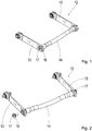
- Fig. 1
- eine perspektivische Darstellung einer Stabilisatoranordnung mit einem Einsatz zur Schwingungsdämpferhalterung,
- Fig. 2
- die Teile nach
Figur 1 - Fig. 3
- eine perspektivische Ansicht einer Fahrwerkanordnung mit zwei achsnah angeordneten Luftfederbälgen und an jeder Seite einem in Verlängerung eines Querrohrs der Stabilisatoranordnung gehaltenen Schwingungsdämpfer,
- Fig. 4
- eine Teildarstellung einer alternativen Fahrwerkanordnung mit zwei voneinander längs beabstandeten Luftfederbälgen und einem an der Stabilisatoranordnung gehaltenen Schwingungsdämpfer,
- Fig. 5
- einen als LKW ausgebildeten Nutzkraftwagen (NKW) in Seitenansicht.
Further advantages and features of the invention will become apparent from the drawing illustrated and described below embodiments of the subject invention.
In the drawing shows:
- Fig. 1
- a perspective view of a stabilizer assembly with an insert for vibration damper mount,
- Fig. 2
- the parts after
FIG. 1 in an exploded view, - Fig. 3
- a perspective view of a suspension arrangement with two arranged close to the air suspension bellows and on each side a held in extension of a cross tube of the stabilizer assembly vibration damper,
- Fig. 4
- a partial view of an alternative suspension arrangement with two mutually longitudinally spaced air spring bellows and a vibration damper held on the stabilizer assembly,
- Fig. 5
- a trained as a truck commercial vehicle (commercial vehicle) in side view.
Ein mit einer oder mehreren erfindungsgemäßen Fahrwerkanordnungen 10 ausgerüstetes Kraftfahrzeug 1 bildet häufig einen Nutzkraftwagen (NKW) wie einen Lastkraftwagen aus und weist einen Fahrzeugrahmen 2 auf. Ein solcher Fahrzeugrahmen 2 kann typisch seitliche Längsträger und mehrere, diese verbindende Querträger umfassen. An dem Fahrzeugrahmen 2 sind eine oder mehrere Fahrwerkanordnungen 10 für eine oder mehrere jeweils Räder 4 tragende Achse(n) 3 angeordnet. Die Achse(n) 3 ist oder sind jeweils quer zur Fahrtrichtung F angeordnet. Bei mehreren Achsen 3 ist es auch möglich, dass die erfindungsgemäße Fahrwerkanordnung 10 nur an einem Teil dieser Achsen, insbesondere an hinteren Achsen, vorgesehen ist.A
Auch beispielsweise ein Baufahrzeug oder ein Offroadfahrzeug kann erfindungsgemäß ausgebildet sein.Also, for example, a construction vehicle or an off-road vehicle may be designed according to the invention.
Eine Fahrwerkanordnung 10 umfasst zur Dämpfung von unerwünschten Schwingungen der Räder 4 jeweils pro Achse 3 zumindest ein Paar von seitlich angeordneten Schwingungsdämpfern 11, die beispielsweise vertikale Anregungen der Achse 3 hemmen. Des Weiteren ist zumindest eine insgesamt mit 12 bezeichnete Stabilisatoranordnung vorgesehen, die über seitliche, längs erstreckte Abschnitte 13 einen quer erstreckten Abschnitt 14 trägt. Diese Stabilisatoranordnung 12 dient zur Wankstabilisierung des Fahrzeugs 1 und ist bei NKW in der Regel ohnehin an diesen vorhanden.A
Dabei ist ein unteres Ende 15 eines jeweiligen Schwingungsdämpfers 11 an der Stabilisatoranordnung 12 gehalten.In this case, a
Der quer erstreckte Abschnitt 14 kann ein Rohrstück umfassen, wie in
In dem in
Bei dieser Anordnung des Schwingungsdämpfers 11 in Verlängerung des quer erstreckten Rohrstücks 14 ist der Flanschkörper 16 mit den offenen Rohrenden verbunden. Die Flanschkörper 16 können dabei zumindest bereichsweise in die Rohrenden eingesteckt und mit diesen beispielsweise verschweißt oder verschraubt sein. Auch eine eingepresste Gummilagerung oder ähnliches kann möglich sein. Die Verbindung ist durch dieses Einstecken konstruktiv und montagetechnisch einfach. Der Einsatz weist durch seine kleine Baugröße ein minimales Gewicht auf und kann in eine ohnehin vorhandene Öffnung der Stabilisatoranordnung 12 eingebracht werden.In this arrangement, the
In den
Ebenso ist es auch möglich, die Erfindung bei solchen Achsen 3 vorzusehen, die über Blattfedern gefedert sind - hier nicht gezeichnet.Likewise, it is also possible to provide the invention in
Eine Längs- und Querführung der Achse 3 über beispielsweise Dreieckslenker 23, wie in
In allen Fällen ist eine Schwingungsdämpferaufnahme 15 in die Stabilisatoranordnung 12 integriert.In all cases, a vibration damper mount 15 is integrated into the
Insbesondere bei achsennah angeordneten Luftfedern 20 ergibt sich so eine bauraumoptimierte Lösung, die sich bei allen Fahrzeugvarianten darstellen lässt. Bei achsennah angeordneten Luftfedern 20 kann dadurch auf aufwendige und gewichtsmäßig nachteilige Anbindungen des Schwingungsdämpfers 11 verzichtet werden.In particular with air springs 20 arranged close to the axis, this results in a space-optimized solution that can be displayed in all vehicle variants. In the case of air springs 20 arranged near the axis, costly and weight-disadvantageous connections of the
- 11
- Kraftfahrzeugmotor vehicle
- 22
- Fahrzeugrahmenvehicle frame
- 33
- Achseaxis
- 44
- Räderbikes
- 1010
- Fahrwerkanordnunglanding gear assembly
- 1111
- Schwingungsdämpfervibration
- 1212
- Stabilisatoranordnungstabilizer assembly
- 1313
- längs erstreckter Abschnittlongitudinally extended section
- 1414
- quer erstreckter Abschnitttransversely stretched section
- 1515
- unteres Ende des Schwingungsdämpferslower end of the vibration damper
- 1616
- Flanschkörperflange
- 1717
- Zapfenspigot
- 1818
- Halterungholder
- 1919
- Lagerwarehouse
- 2020
- Luftfederbälgeair suspension bellows
- 2121
- Luftfederbälgeair suspension bellows
- 2222
- Nahbereichclose range
- 2323
- Dreiecklenkerwishbone
Claims (5)
- Chassis arrangement (10), in particular for commercial vehicles (1), having at least one axle (3) which extends transversely with respect to the driving direction, supports wheels (4) and is suspended via air springs (20), the movement of the axle (3) being damped via vibration dampers (11) which are provided with end sections (15), and having at least one anti-roll bar arrangement (12), consisting of two longitudinally extending sections (13) and a transversely extending section (14) which connects them, characterized in that an end section (15) of the vibration damper (11) is held directly on the anti-roll bar arrangement (12) on an extension (16, 17) of the transversely extending section (14) beyond the longitudinally extending section (13) and is connected to the said anti-roll bar arrangement (12), and in that two air springs (20) are provided per axle (3) on each vehicle transverse side at a smallest possible spacing from one another above the axle.
- Chassis arrangement (10) according to Claim 1, characterized in that the connection of the vibration damper (11) to the anti-roll bar arrangement (12) takes place via separate flange bodies (16) which are provided in each case with an outwardly pointing pin (17) .
- Chassis arrangement (10) according to Claim 2, characterized in that the flange body (16) is plugged at least in regions into the transversely extending section (14) of the anti-roll bar arrangement (12).
- Chassis arrangement (10) according to one of Claims 1 to 3, characterized in that the lower end of the vibration damper (11) is held as an extension of a transversely extending tubular piece of the anti-roll bar arrangement (12).
- Motor vehicle (1), in particular commercial vehicle, having at least one chassis arrangement (10) according to one of Claims 1 to 4.
Applications Claiming Priority (2)
| Application Number | Priority Date | Filing Date | Title |
|---|---|---|---|
| DE102014202831.0A DE102014202831A1 (en) | 2014-02-17 | 2014-02-17 | Suspension arrangement for a motor vehicle |
| PCT/EP2015/050384 WO2015121006A1 (en) | 2014-02-17 | 2015-01-12 | Chassis system for a motor vehicle |
Publications (2)
| Publication Number | Publication Date |
|---|---|
| EP3107743A1 EP3107743A1 (en) | 2016-12-28 |
| EP3107743B1 true EP3107743B1 (en) | 2019-02-27 |
Family
ID=52339147
Family Applications (1)
| Application Number | Title | Priority Date | Filing Date |
|---|---|---|---|
| EP15700138.9A Active EP3107743B1 (en) | 2014-02-17 | 2015-01-12 | Chassis system for a motor vehicle |
Country Status (9)
| Country | Link |
|---|---|
| US (1) | US10214068B2 (en) |
| EP (1) | EP3107743B1 (en) |
| JP (1) | JP6421193B2 (en) |
| KR (1) | KR102236508B1 (en) |
| CN (1) | CN106061767B (en) |
| BR (1) | BR112016017375B1 (en) |
| DE (1) | DE102014202831A1 (en) |
| RU (1) | RU2675039C2 (en) |
| WO (1) | WO2015121006A1 (en) |
Families Citing this family (6)
| Publication number | Priority date | Publication date | Assignee | Title |
|---|---|---|---|---|
| DE102015214456A1 (en) * | 2015-07-30 | 2017-02-02 | Deere & Company | Cabin storage arrangement for a commercial vehicle |
| DE102016007367A1 (en) * | 2016-06-16 | 2017-10-19 | Hochschule für Angewandte Wissenschaft und Kunst - Hildesheim/Holzminden/Göttingen | Rigid chassis for commercial vehicles |
| US11273679B2 (en) * | 2016-12-06 | 2022-03-15 | Volvo Truck Corporation | Stabilizer bar and stabilization method |
| US10759251B1 (en) | 2017-04-27 | 2020-09-01 | Oshkosh Defense, Llc | Sway bar and bushing systems and methods |
| RU200694U1 (en) * | 2020-07-17 | 2020-11-05 | Публичное акционерное общество "КАМАЗ" | BALANCING SPRING SUSPENSION OF THE VEHICLE |
| US20230074504A1 (en) * | 2021-09-09 | 2023-03-09 | Oshkosh Corporation | Systems and methods for vehicle suspension assemblies |
Family Cites Families (30)
| Publication number | Priority date | Publication date | Assignee | Title |
|---|---|---|---|---|
| US1971960A (en) * | 1934-05-08 | 1934-08-28 | Huntman Stabilizer Corp | Combined crossbar equalizing and shock absorbing means for vehicles |
| US2186279A (en) * | 1938-12-27 | 1940-01-09 | Yellow Truck & Coach Mfg Co | Sway stabilizer |
| US4343375A (en) | 1979-10-22 | 1982-08-10 | Manning Donald L | Vehicle drive wheel suspension |
| IT1223976B (en) * | 1988-12-07 | 1990-09-29 | Fiat Auto Spa | INDEPENDENT WHEEL REAR SUSPENSION |
| DE19521875C2 (en) * | 1995-06-16 | 2002-04-18 | Zf Lemfoerder Metallwaren Ag | Axle suspension for rigid axles in vehicles |
| DE19624242A1 (en) * | 1996-06-18 | 1997-09-18 | Daimler Benz Ag | Vehicle front wheel suspension with rigid axle |
| JPH10138727A (en) * | 1996-11-14 | 1998-05-26 | Nissan Motor Co Ltd | Suspension structure |
| US6056305A (en) * | 1997-11-03 | 2000-05-02 | Pribyl; Myron | Steering axle suspension system |
| DE19809203A1 (en) * | 1998-03-04 | 1999-09-09 | Man Nutzfahrzeuge Ag | Chassis of a heavy commercial vehicle |
| EP1077819B1 (en) * | 1999-03-02 | 2003-10-22 | ZF Lemförder Metallwaren AG | Axle suspension of rigid axles |
| DE10037890A1 (en) | 2000-08-03 | 2002-02-21 | Thyssen Krupp Automotive Ag | Tilting device for driver's cab has rocker arm and/or revolving rod on one side of carrier part of fixing stand and spring or spring damping unit on other side |
| DE10118623A1 (en) * | 2001-05-18 | 2002-12-05 | Zf Lemfoerder Metallwaren Ag | axle rocker |
| JP2003341326A (en) * | 2002-05-27 | 2003-12-03 | Hino Motors Ltd | Axle-holding structure |
| US6733020B2 (en) * | 2002-07-12 | 2004-05-11 | Arvinmeritor Technology, Llc | Suspension trailing arm |
| US7234713B1 (en) * | 2003-02-21 | 2007-06-26 | Link Mfg. Ltd. | Axle suspension system |
| CA2540070A1 (en) * | 2003-10-01 | 2005-04-14 | Dana Corporation | Steer axle suspension |
| JP4449708B2 (en) * | 2004-07-21 | 2010-04-14 | 日産自動車株式会社 | Wheel suspension |
| US20060244236A1 (en) * | 2005-04-27 | 2006-11-02 | Cortez Jerome L | Vehicle suspensions having leaf springs and alternative clamp groups |
| US7744708B2 (en) * | 2006-03-14 | 2010-06-29 | Tenaris Connections Limited | Methods of producing high-strength metal tubular bars possessing improved cold formability |
| US7717441B2 (en) * | 2006-12-12 | 2010-05-18 | International Truck Intellectual Property Company, Llc | Suspension mounting crossmember with integrated cab mounts for vehicle having front multilink suspension |
| DE102007008325A1 (en) * | 2007-02-16 | 2008-08-21 | Zf Friedrichshafen Ag | Rigid axle for a commercial vehicle |
| CN201045008Y (en) * | 2007-06-21 | 2008-04-09 | 东风汽车有限公司 | Full-air rear suspension device of automobile |
| MX2010002402A (en) * | 2007-09-05 | 2010-04-01 | Magna Int Inc | Twist beam with interlock. |
| US20100044988A1 (en) * | 2008-08-20 | 2010-02-25 | International Truck Intellectual Property Company Llc | Integrated Swaybar and Torque Rod Suspension Link |
| US20100072723A1 (en) * | 2008-09-24 | 2010-03-25 | Andrew Ciasulli | Adjustable Over Tube Anti Roll Bar |
| DE102008049940A1 (en) * | 2008-10-02 | 2010-04-08 | Zf Friedrichshafen Ag | Hollow shaft connecting device |
| EP2338706A1 (en) * | 2009-12-22 | 2011-06-29 | IVECO FIAT S.p.A. | Suspension unit for a front axle of an industrial or commercial vehicle with damper struts and a transverse leaf spring |
| CA2690484C (en) * | 2010-01-20 | 2014-03-25 | Raydan Manufacturing Inc. | Axle suspension |
| CN203093666U (en) * | 2013-01-25 | 2013-07-31 | 中国公路车辆机械有限公司 | Pneumatic suspension frame with supporting axle |
| US9150078B2 (en) * | 2013-10-18 | 2015-10-06 | GM Global Technology Operations LLC | Vehicle suspension apparatus with bar and body load reaction component for ride height management |
-
2014
- 2014-02-17 DE DE102014202831.0A patent/DE102014202831A1/en not_active Withdrawn
-
2015
- 2015-01-12 CN CN201580008331.2A patent/CN106061767B/en active Active
- 2015-01-12 US US15/119,196 patent/US10214068B2/en active Active
- 2015-01-12 EP EP15700138.9A patent/EP3107743B1/en active Active
- 2015-01-12 JP JP2016549026A patent/JP6421193B2/en active Active
- 2015-01-12 WO PCT/EP2015/050384 patent/WO2015121006A1/en active Application Filing
- 2015-01-12 BR BR112016017375-9A patent/BR112016017375B1/en active IP Right Grant
- 2015-01-12 RU RU2016136995A patent/RU2675039C2/en active
- 2015-01-12 KR KR1020167025446A patent/KR102236508B1/en active IP Right Grant
Non-Patent Citations (1)
| Title |
|---|
| None * |
Also Published As
| Publication number | Publication date |
|---|---|
| DE102014202831A1 (en) | 2015-08-20 |
| JP6421193B2 (en) | 2018-11-07 |
| KR20160122819A (en) | 2016-10-24 |
| JP2017507830A (en) | 2017-03-23 |
| KR102236508B1 (en) | 2021-04-08 |
| BR112016017375A2 (en) | 2017-08-08 |
| CN106061767B (en) | 2019-08-13 |
| US10214068B2 (en) | 2019-02-26 |
| RU2016136995A3 (en) | 2018-07-09 |
| BR112016017375B1 (en) | 2022-09-27 |
| RU2016136995A (en) | 2018-03-22 |
| EP3107743A1 (en) | 2016-12-28 |
| RU2675039C2 (en) | 2018-12-14 |
| CN106061767A (en) | 2016-10-26 |
| US20170008361A1 (en) | 2017-01-12 |
| WO2015121006A1 (en) | 2015-08-20 |
Similar Documents
| Publication | Publication Date | Title |
|---|---|---|
| EP3107743B1 (en) | Chassis system for a motor vehicle | |
| DE19920051B4 (en) | Subframe for a front axle of a motor vehicle | |
| DE102014205632A1 (en) | Independent and rear suspension with independent wheel suspension for a vehicle and vehicle equipped accordingly | |
| DE102016220786A1 (en) | Rear suspension for motor vehicles | |
| DE102012217416A1 (en) | Tilting vehicle suspension | |
| DE102014113333A1 (en) | Coupled-beam axle type suspension system | |
| DE102008062901A1 (en) | Composite guide rear axle for motor vehicle rear carriage, has trailing arm coupled with front end portion of vehicle structure, where cross bar of trailing arm is connected with each other in area of wheel carrier | |
| DE102014205635A1 (en) | Independent and rear suspension with independent wheel suspension for a vehicle and vehicle equipped accordingly | |
| DE102007052632A1 (en) | Beam axle | |
| DE202017100164U1 (en) | Rear suspension for motor vehicles | |
| DE102015012928A1 (en) | Vibration damper and axle carrier with the same | |
| DE102015210151A1 (en) | Method for mounting the vibration dampers of a two-lane two-axle vehicle | |
| DE102013002285A1 (en) | Axle guide, particularly transverse-link according to Panhard rod for an axle, particularly rear axle of motor vehicle, has component fastened directly or indirectly at chassis of motor vehicle or on vehicle body | |
| DE102014109887A1 (en) | Vehicle body reinforcement structure | |
| DE102014218735A1 (en) | Suspension arrangement for a vehicle with at least one liftable axle and support of such an axle | |
| DE202014101432U1 (en) | Independent and rear suspension with independent wheel suspension for a vehicle and vehicle equipped accordingly | |
| DE102013218701B3 (en) | Twist-beam axle for a vehicle and bearing arrangement for a torsion-beam axle | |
| DE102011086517A1 (en) | Rigid axle with air suspension | |
| DE102011081495A1 (en) | Wheel suspension for vehicle, has upper wishbone and rocker arranged in common bearing points at structure or suspension subframe of vehicle, where lower wishbone and rocker are connected over strut | |
| DE102012218985A1 (en) | Multi-steering wheel axle i.e. rear axle, of motor vehicle, has camber arm including recess or aperture in which spring rebounds with support point of arm so that point is located in horizon direction below plane of recess or aperture | |
| DE102012209570A1 (en) | Wheel suspension for steerable vehicle wheel, has transverse control arm and tie rod, which are connected by coupling element, so that tie rod is pressurized with restoring force to steering restoring position in deflection of tie rod | |
| DE19911340A1 (en) | Wheel suspension for a motor vehicle | |
| DE102012003450A1 (en) | Driving cab suspension for commercial vehicle i.e. load motor car, has spring steering wheel damper unit comprising composite component formed as fiber reinforced plastic or plate spring, where component forms steering wheel and stabilizer | |
| DE102021204965A1 (en) | Coupling device for connecting a leaf spring to a wheel carrier of a motor vehicle wheel suspension and motor vehicle wheel suspension with such a coupling device | |
| DE102014218734A1 (en) | Chassis arrangement with at least one liftable axle and carrier of such an axle |
Legal Events
| Date | Code | Title | Description |
|---|---|---|---|
| PUAI | Public reference made under article 153(3) epc to a published international application that has entered the european phase |
Free format text: ORIGINAL CODE: 0009012 |
|
| STAA | Information on the status of an ep patent application or granted ep patent |
Free format text: STATUS: REQUEST FOR EXAMINATION WAS MADE |
|
| 17P | Request for examination filed |
Effective date: 20160718 |
|
| AK | Designated contracting states |
Kind code of ref document: A1 Designated state(s): AL AT BE BG CH CY CZ DE DK EE ES FI FR GB GR HR HU IE IS IT LI LT LU LV MC MK MT NL NO PL PT RO RS SE SI SK SM TR |
|
| AX | Request for extension of the european patent |
Extension state: BA ME |
|
| DAX | Request for extension of the european patent (deleted) | ||
| STAA | Information on the status of an ep patent application or granted ep patent |
Free format text: STATUS: EXAMINATION IS IN PROGRESS |
|
| 17Q | First examination report despatched |
Effective date: 20171019 |
|
| GRAP | Despatch of communication of intention to grant a patent |
Free format text: ORIGINAL CODE: EPIDOSNIGR1 |
|
| STAA | Information on the status of an ep patent application or granted ep patent |
Free format text: STATUS: GRANT OF PATENT IS INTENDED |
|
| INTG | Intention to grant announced |
Effective date: 20181009 |
|
| RIN1 | Information on inventor provided before grant (corrected) |
Inventor name: BUHL, MANFRED Inventor name: BACKX, JASPER JOSHUA Inventor name: VAN DER KNAAP, ALBERTUS CLEMENS MARIA Inventor name: HELM, EIKE Inventor name: EISMANN, JENS Inventor name: RAUE, VICTOR Inventor name: LANGHORST, FRIEDHELM |
|
| GRAS | Grant fee paid |
Free format text: ORIGINAL CODE: EPIDOSNIGR3 |
|
| GRAA | (expected) grant |
Free format text: ORIGINAL CODE: 0009210 |
|
| STAA | Information on the status of an ep patent application or granted ep patent |
Free format text: STATUS: THE PATENT HAS BEEN GRANTED |
|
| AK | Designated contracting states |
Kind code of ref document: B1 Designated state(s): AL AT BE BG CH CY CZ DE DK EE ES FI FR GB GR HR HU IE IS IT LI LT LU LV MC MK MT NL NO PL PT RO RS SE SI SK SM TR |
|
| REG | Reference to a national code |
Ref country code: GB Ref legal event code: FG4D Free format text: NOT ENGLISH |
|
| REG | Reference to a national code |
Ref country code: CH Ref legal event code: EP |
|
| REG | Reference to a national code |
Ref country code: AT Ref legal event code: REF Ref document number: 1100797 Country of ref document: AT Kind code of ref document: T Effective date: 20190315 |
|
| REG | Reference to a national code |
Ref country code: IE Ref legal event code: FG4D Free format text: LANGUAGE OF EP DOCUMENT: GERMAN |
|
| REG | Reference to a national code |
Ref country code: DE Ref legal event code: R096 Ref document number: 502015008115 Country of ref document: DE |
|
| REG | Reference to a national code |
Ref country code: NL Ref legal event code: FP |
|
| REG | Reference to a national code |
Ref country code: SE Ref legal event code: TRGR |
|
| REG | Reference to a national code |
Ref country code: LT Ref legal event code: MG4D |
|
| PG25 | Lapsed in a contracting state [announced via postgrant information from national office to epo] |
Ref country code: NO Free format text: LAPSE BECAUSE OF FAILURE TO SUBMIT A TRANSLATION OF THE DESCRIPTION OR TO PAY THE FEE WITHIN THE PRESCRIBED TIME-LIMIT Effective date: 20190527 Ref country code: PT Free format text: LAPSE BECAUSE OF FAILURE TO SUBMIT A TRANSLATION OF THE DESCRIPTION OR TO PAY THE FEE WITHIN THE PRESCRIBED TIME-LIMIT Effective date: 20190627 Ref country code: LT Free format text: LAPSE BECAUSE OF FAILURE TO SUBMIT A TRANSLATION OF THE DESCRIPTION OR TO PAY THE FEE WITHIN THE PRESCRIBED TIME-LIMIT Effective date: 20190227 Ref country code: FI Free format text: LAPSE BECAUSE OF FAILURE TO SUBMIT A TRANSLATION OF THE DESCRIPTION OR TO PAY THE FEE WITHIN THE PRESCRIBED TIME-LIMIT Effective date: 20190227 |
|
| PG25 | Lapsed in a contracting state [announced via postgrant information from national office to epo] |
Ref country code: RS Free format text: LAPSE BECAUSE OF FAILURE TO SUBMIT A TRANSLATION OF THE DESCRIPTION OR TO PAY THE FEE WITHIN THE PRESCRIBED TIME-LIMIT Effective date: 20190227 Ref country code: BG Free format text: LAPSE BECAUSE OF FAILURE TO SUBMIT A TRANSLATION OF THE DESCRIPTION OR TO PAY THE FEE WITHIN THE PRESCRIBED TIME-LIMIT Effective date: 20190527 Ref country code: IS Free format text: LAPSE BECAUSE OF FAILURE TO SUBMIT A TRANSLATION OF THE DESCRIPTION OR TO PAY THE FEE WITHIN THE PRESCRIBED TIME-LIMIT Effective date: 20190627 Ref country code: LV Free format text: LAPSE BECAUSE OF FAILURE TO SUBMIT A TRANSLATION OF THE DESCRIPTION OR TO PAY THE FEE WITHIN THE PRESCRIBED TIME-LIMIT Effective date: 20190227 Ref country code: HR Free format text: LAPSE BECAUSE OF FAILURE TO SUBMIT A TRANSLATION OF THE DESCRIPTION OR TO PAY THE FEE WITHIN THE PRESCRIBED TIME-LIMIT Effective date: 20190227 Ref country code: GR Free format text: LAPSE BECAUSE OF FAILURE TO SUBMIT A TRANSLATION OF THE DESCRIPTION OR TO PAY THE FEE WITHIN THE PRESCRIBED TIME-LIMIT Effective date: 20190528 |
|
| PG25 | Lapsed in a contracting state [announced via postgrant information from national office to epo] |
Ref country code: SK Free format text: LAPSE BECAUSE OF FAILURE TO SUBMIT A TRANSLATION OF THE DESCRIPTION OR TO PAY THE FEE WITHIN THE PRESCRIBED TIME-LIMIT Effective date: 20190227 Ref country code: EE Free format text: LAPSE BECAUSE OF FAILURE TO SUBMIT A TRANSLATION OF THE DESCRIPTION OR TO PAY THE FEE WITHIN THE PRESCRIBED TIME-LIMIT Effective date: 20190227 Ref country code: DK Free format text: LAPSE BECAUSE OF FAILURE TO SUBMIT A TRANSLATION OF THE DESCRIPTION OR TO PAY THE FEE WITHIN THE PRESCRIBED TIME-LIMIT Effective date: 20190227 Ref country code: ES Free format text: LAPSE BECAUSE OF FAILURE TO SUBMIT A TRANSLATION OF THE DESCRIPTION OR TO PAY THE FEE WITHIN THE PRESCRIBED TIME-LIMIT Effective date: 20190227 Ref country code: AL Free format text: LAPSE BECAUSE OF FAILURE TO SUBMIT A TRANSLATION OF THE DESCRIPTION OR TO PAY THE FEE WITHIN THE PRESCRIBED TIME-LIMIT Effective date: 20190227 Ref country code: CZ Free format text: LAPSE BECAUSE OF FAILURE TO SUBMIT A TRANSLATION OF THE DESCRIPTION OR TO PAY THE FEE WITHIN THE PRESCRIBED TIME-LIMIT Effective date: 20190227 Ref country code: RO Free format text: LAPSE BECAUSE OF FAILURE TO SUBMIT A TRANSLATION OF THE DESCRIPTION OR TO PAY THE FEE WITHIN THE PRESCRIBED TIME-LIMIT Effective date: 20190227 |
|
| REG | Reference to a national code |
Ref country code: DE Ref legal event code: R097 Ref document number: 502015008115 Country of ref document: DE |
|
| PG25 | Lapsed in a contracting state [announced via postgrant information from national office to epo] |
Ref country code: PL Free format text: LAPSE BECAUSE OF FAILURE TO SUBMIT A TRANSLATION OF THE DESCRIPTION OR TO PAY THE FEE WITHIN THE PRESCRIBED TIME-LIMIT Effective date: 20190227 Ref country code: SM Free format text: LAPSE BECAUSE OF FAILURE TO SUBMIT A TRANSLATION OF THE DESCRIPTION OR TO PAY THE FEE WITHIN THE PRESCRIBED TIME-LIMIT Effective date: 20190227 |
|
| PLBE | No opposition filed within time limit |
Free format text: ORIGINAL CODE: 0009261 |
|
| STAA | Information on the status of an ep patent application or granted ep patent |
Free format text: STATUS: NO OPPOSITION FILED WITHIN TIME LIMIT |
|
| 26N | No opposition filed |
Effective date: 20191128 |
|
| PG25 | Lapsed in a contracting state [announced via postgrant information from national office to epo] |
Ref country code: SI Free format text: LAPSE BECAUSE OF FAILURE TO SUBMIT A TRANSLATION OF THE DESCRIPTION OR TO PAY THE FEE WITHIN THE PRESCRIBED TIME-LIMIT Effective date: 20190227 |
|
| PG25 | Lapsed in a contracting state [announced via postgrant information from national office to epo] |
Ref country code: TR Free format text: LAPSE BECAUSE OF FAILURE TO SUBMIT A TRANSLATION OF THE DESCRIPTION OR TO PAY THE FEE WITHIN THE PRESCRIBED TIME-LIMIT Effective date: 20190227 |
|
| PG25 | Lapsed in a contracting state [announced via postgrant information from national office to epo] |
Ref country code: MC Free format text: LAPSE BECAUSE OF FAILURE TO SUBMIT A TRANSLATION OF THE DESCRIPTION OR TO PAY THE FEE WITHIN THE PRESCRIBED TIME-LIMIT Effective date: 20190227 |
|
| REG | Reference to a national code |
Ref country code: CH Ref legal event code: PL |
|
| REG | Reference to a national code |
Ref country code: BE Ref legal event code: MM Effective date: 20200131 |
|
| PG25 | Lapsed in a contracting state [announced via postgrant information from national office to epo] |
Ref country code: LU Free format text: LAPSE BECAUSE OF NON-PAYMENT OF DUE FEES Effective date: 20200112 |
|
| PG25 | Lapsed in a contracting state [announced via postgrant information from national office to epo] |
Ref country code: CH Free format text: LAPSE BECAUSE OF NON-PAYMENT OF DUE FEES Effective date: 20200131 Ref country code: LI Free format text: LAPSE BECAUSE OF NON-PAYMENT OF DUE FEES Effective date: 20200131 Ref country code: BE Free format text: LAPSE BECAUSE OF NON-PAYMENT OF DUE FEES Effective date: 20200131 |
|
| PG25 | Lapsed in a contracting state [announced via postgrant information from national office to epo] |
Ref country code: IE Free format text: LAPSE BECAUSE OF NON-PAYMENT OF DUE FEES Effective date: 20200112 |
|
| REG | Reference to a national code |
Ref country code: AT Ref legal event code: MM01 Ref document number: 1100797 Country of ref document: AT Kind code of ref document: T Effective date: 20200112 |
|
| PG25 | Lapsed in a contracting state [announced via postgrant information from national office to epo] |
Ref country code: AT Free format text: LAPSE BECAUSE OF NON-PAYMENT OF DUE FEES Effective date: 20200112 |
|
| PG25 | Lapsed in a contracting state [announced via postgrant information from national office to epo] |
Ref country code: MT Free format text: LAPSE BECAUSE OF FAILURE TO SUBMIT A TRANSLATION OF THE DESCRIPTION OR TO PAY THE FEE WITHIN THE PRESCRIBED TIME-LIMIT Effective date: 20190227 Ref country code: CY Free format text: LAPSE BECAUSE OF FAILURE TO SUBMIT A TRANSLATION OF THE DESCRIPTION OR TO PAY THE FEE WITHIN THE PRESCRIBED TIME-LIMIT Effective date: 20190227 |
|
| PG25 | Lapsed in a contracting state [announced via postgrant information from national office to epo] |
Ref country code: MK Free format text: LAPSE BECAUSE OF FAILURE TO SUBMIT A TRANSLATION OF THE DESCRIPTION OR TO PAY THE FEE WITHIN THE PRESCRIBED TIME-LIMIT Effective date: 20190227 |
|
| PGFP | Annual fee paid to national office [announced via postgrant information from national office to epo] |
Ref country code: IT Payment date: 20221213 Year of fee payment: 9 Ref country code: DE Payment date: 20221123 Year of fee payment: 9 |
|
| PGFP | Annual fee paid to national office [announced via postgrant information from national office to epo] |
Ref country code: GB Payment date: 20231130 Year of fee payment: 10 |
|
| PGFP | Annual fee paid to national office [announced via postgrant information from national office to epo] |
Ref country code: SE Payment date: 20231213 Year of fee payment: 10 Ref country code: NL Payment date: 20231215 Year of fee payment: 10 Ref country code: FR Payment date: 20231212 Year of fee payment: 10 |