EP3107474B1 - Mehrfachanzeigesteuerungsvorrichtung für ein chirurgisches system - Google Patents
Mehrfachanzeigesteuerungsvorrichtung für ein chirurgisches system Download PDFInfo
- Publication number
- EP3107474B1 EP3107474B1 EP15709758.5A EP15709758A EP3107474B1 EP 3107474 B1 EP3107474 B1 EP 3107474B1 EP 15709758 A EP15709758 A EP 15709758A EP 3107474 B1 EP3107474 B1 EP 3107474B1
- Authority
- EP
- European Patent Office
- Prior art keywords
- display
- information
- user
- hmd
- users
- Prior art date
- Legal status (The legal status is an assumption and is not a legal conclusion. Google has not performed a legal analysis and makes no representation as to the accuracy of the status listed.)
- Active
Links
Images


Classifications
-
- G—PHYSICS
- G16—INFORMATION AND COMMUNICATION TECHNOLOGY [ICT] SPECIALLY ADAPTED FOR SPECIFIC APPLICATION FIELDS
- G16H—HEALTHCARE INFORMATICS, i.e. INFORMATION AND COMMUNICATION TECHNOLOGY [ICT] SPECIALLY ADAPTED FOR THE HANDLING OR PROCESSING OF MEDICAL OR HEALTHCARE DATA
- G16H20/00—ICT specially adapted for therapies or health-improving plans, e.g. for handling prescriptions, for steering therapy or for monitoring patient compliance
- G16H20/40—ICT specially adapted for therapies or health-improving plans, e.g. for handling prescriptions, for steering therapy or for monitoring patient compliance relating to mechanical, radiation or invasive therapies, e.g. surgery, laser therapy, dialysis or acupuncture
-
- A—HUMAN NECESSITIES
- A61—MEDICAL OR VETERINARY SCIENCE; HYGIENE
- A61B—DIAGNOSIS; SURGERY; IDENTIFICATION
- A61B1/00—Instruments for performing medical examinations of the interior of cavities or tubes of the body by visual or photographical inspection, e.g. endoscopes; Illuminating arrangements therefor
- A61B1/00002—Operational features of endoscopes
- A61B1/00043—Operational features of endoscopes provided with output arrangements
- A61B1/00045—Display arrangement
- A61B1/0005—Display arrangement combining images e.g. side-by-side, superimposed or tiled
-
- A—HUMAN NECESSITIES
- A61—MEDICAL OR VETERINARY SCIENCE; HYGIENE
- A61B—DIAGNOSIS; SURGERY; IDENTIFICATION
- A61B1/00—Instruments for performing medical examinations of the interior of cavities or tubes of the body by visual or photographical inspection, e.g. endoscopes; Illuminating arrangements therefor
- A61B1/00002—Operational features of endoscopes
- A61B1/00043—Operational features of endoscopes provided with output arrangements
- A61B1/00055—Operational features of endoscopes provided with output arrangements for alerting the user
-
- A—HUMAN NECESSITIES
- A61—MEDICAL OR VETERINARY SCIENCE; HYGIENE
- A61B—DIAGNOSIS; SURGERY; IDENTIFICATION
- A61B34/00—Computer-aided surgery; Manipulators or robots specially adapted for use in surgery
- A61B34/25—User interfaces for surgical systems
-
- A—HUMAN NECESSITIES
- A61—MEDICAL OR VETERINARY SCIENCE; HYGIENE
- A61B—DIAGNOSIS; SURGERY; IDENTIFICATION
- A61B90/00—Instruments, implements or accessories specially adapted for surgery or diagnosis and not covered by any of the groups A61B1/00 - A61B50/00, e.g. for luxation treatment or for protecting wound edges
- A61B90/36—Image-producing devices or illumination devices not otherwise provided for
-
- A—HUMAN NECESSITIES
- A61—MEDICAL OR VETERINARY SCIENCE; HYGIENE
- A61B—DIAGNOSIS; SURGERY; IDENTIFICATION
- A61B90/00—Instruments, implements or accessories specially adapted for surgery or diagnosis and not covered by any of the groups A61B1/00 - A61B50/00, e.g. for luxation treatment or for protecting wound edges
- A61B90/50—Supports for surgical instruments, e.g. articulated arms
-
- G—PHYSICS
- G02—OPTICS
- G02B—OPTICAL ELEMENTS, SYSTEMS OR APPARATUS
- G02B27/00—Optical systems or apparatus not provided for by any of the groups G02B1/00 - G02B26/00, G02B30/00
- G02B27/01—Head-up displays
- G02B27/017—Head mounted
-
- G—PHYSICS
- G06—COMPUTING OR CALCULATING; COUNTING
- G06F—ELECTRIC DIGITAL DATA PROCESSING
- G06F3/00—Input arrangements for transferring data to be processed into a form capable of being handled by the computer; Output arrangements for transferring data from processing unit to output unit, e.g. interface arrangements
- G06F3/14—Digital output to display device ; Cooperation and interconnection of the display device with other functional units
- G06F3/1454—Digital output to display device ; Cooperation and interconnection of the display device with other functional units involving copying of the display data of a local workstation or window to a remote workstation or window so that an actual copy of the data is displayed simultaneously on two or more displays, e.g. teledisplay
-
- G—PHYSICS
- G16—INFORMATION AND COMMUNICATION TECHNOLOGY [ICT] SPECIALLY ADAPTED FOR SPECIFIC APPLICATION FIELDS
- G16H—HEALTHCARE INFORMATICS, i.e. INFORMATION AND COMMUNICATION TECHNOLOGY [ICT] SPECIALLY ADAPTED FOR THE HANDLING OR PROCESSING OF MEDICAL OR HEALTHCARE DATA
- G16H40/00—ICT specially adapted for the management or administration of healthcare resources or facilities; ICT specially adapted for the management or operation of medical equipment or devices
- G16H40/60—ICT specially adapted for the management or administration of healthcare resources or facilities; ICT specially adapted for the management or operation of medical equipment or devices for the operation of medical equipment or devices
- G16H40/63—ICT specially adapted for the management or administration of healthcare resources or facilities; ICT specially adapted for the management or operation of medical equipment or devices for the operation of medical equipment or devices for local operation
-
- A—HUMAN NECESSITIES
- A61—MEDICAL OR VETERINARY SCIENCE; HYGIENE
- A61B—DIAGNOSIS; SURGERY; IDENTIFICATION
- A61B90/00—Instruments, implements or accessories specially adapted for surgery or diagnosis and not covered by any of the groups A61B1/00 - A61B50/00, e.g. for luxation treatment or for protecting wound edges
- A61B90/36—Image-producing devices or illumination devices not otherwise provided for
- A61B2090/364—Correlation of different images or relation of image positions in respect to the body
- A61B2090/365—Correlation of different images or relation of image positions in respect to the body augmented reality, i.e. correlating a live optical image with another image
-
- A—HUMAN NECESSITIES
- A61—MEDICAL OR VETERINARY SCIENCE; HYGIENE
- A61B—DIAGNOSIS; SURGERY; IDENTIFICATION
- A61B90/00—Instruments, implements or accessories specially adapted for surgery or diagnosis and not covered by any of the groups A61B1/00 - A61B50/00, e.g. for luxation treatment or for protecting wound edges
- A61B90/36—Image-producing devices or illumination devices not otherwise provided for
- A61B2090/364—Correlation of different images or relation of image positions in respect to the body
- A61B2090/368—Correlation of different images or relation of image positions in respect to the body changing the image on a display according to the operator's position
-
- A—HUMAN NECESSITIES
- A61—MEDICAL OR VETERINARY SCIENCE; HYGIENE
- A61B—DIAGNOSIS; SURGERY; IDENTIFICATION
- A61B90/00—Instruments, implements or accessories specially adapted for surgery or diagnosis and not covered by any of the groups A61B1/00 - A61B50/00, e.g. for luxation treatment or for protecting wound edges
- A61B90/50—Supports for surgical instruments, e.g. articulated arms
- A61B2090/502—Headgear, e.g. helmet, spectacles
Definitions
- the present disclosure relates to a display control device that controls information to be displayed on a display device used by a plurality of users, a display device, a surgical endoscopic system and a display control system.
- the HMD is a display device that is mounted on the head of a user when used and in recent years, the HMD is not only used as AV equipment and a display device for a computer game etc. but also used as a display device for a user to check information while working in working environment.
- the HMD is used as a display device for displaying an image of an endoscope (e.g., PTLs 1, 2).
- An operator wears the HMD and performs an operation while viewing an image displayed on the HMD.
- an image of the endoscope was usually displayed on a monitor installed in the vicinity of the operator, and therefore, it was necessary for the operator to frequently move his/her visual line between the monitor and a patient.
- By displaying the image of the endoscope on the HMD it is made possible for an operator to check the image of the endoscope displayed on the display unit of the HMD and a patient without moving his/her visual line considerably.
- an HMD of type that covers the eyes of a person who wears the HMD it is not possible to recognize peripheral environment, and therefore, it becomes difficult to establish communications during the operation, such as giving instructions to an assistant or a nurse.
- an HMD of video see-through type that mounts a camera on the HMD to allow viewing peripheral environment. If a video see-through function is added to the HMD, an operator who is wearing the HMD is enabled to recognize the situations of staffs around the operator by switching between the endoscope image and external camera image during the operation, and therefore, it is conceivable that communication will be improved.
- a display control device including a display control unit configured to display pieces of information which a plurality of users each wearing a head mounted display visually recognize, respectively, on a display unit that the respective users each wearing the head mounted display are able to visually recognize.
- a display device including a display unit, and a display control unit configured to display pieces of information which a plurality of users each wearing a head mounted display visually recognize, respectively, on a display unit that the respective users each wearing the head mounted display are able to visually recognize.
- a display control system including a plurality of head mounted displays, and a display control device configured to control pieces of information displayed on the head mounted displays, the head mounted displays and the display control device being communicatively connected.
- the display control device outputs information selected by a user wearing the head mounted display and pieces of information that the respective other users each wearing a head mounted display visually recognize to each of the head mounted displays.
- pieces of information visually recognized by users each wearing a head mounted display are displayed respectively on the display unit of each head mounted display. Due to this, it is possible for each user to recognize what other users are viewing.
- each user is able to recognize what other users are viewing, which enables to improve the communication with other persons when each wearing the head mounted display.
- FIG. 1 is a system configuration diagram showing a configuration example of an endoscope system 1 according to the present embodiment.
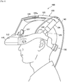
- FIG. 2 is a schematic side view showing a state where a user wears an HMD 100 according to the present embodiment.
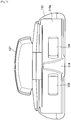
- FIG. 3 is a schematic diagram showing display units 152 and 154 of the HMD 100.
- the endoscope system 1 is a system used in an endoscopic operation and an operator wears an HMD and performs an operation while visually recognizing the state of an affected area the image of which is captured by an endoscope device.
- the endoscope system 1 has a configuration in which the HMDs 100 (100A, 100B), a display 300, and external devices 400 (400A, 400B) are connected to a processor unit 200.
- the HMD 100 is a display device that displays information, such as input image from the external device 400.
- the HMD 100 is, for example, a non-transmissive HMD in the shape of goggles and is used in a state of being mounted on the head of a user.
- the HMD 100 includes a main body unit 110 including the display units 152 and 154 for presenting information to the user, and an upper fixing unit 120 and a rear fixing unit 130 for fixing the main body unit 110 to the head.
- the display units 152 and 154 of the main body unit 110 are located in front of the left and right eyes of the user.
- the main body unit 110 is a portion that covers both the eyes of the user.
- the main body unit 110 may be configured so as to cover, for example, the parts in the vicinity of the left and right temples of the user.
- By forming the main body unit 110 into such a shape it is possible to cover the parts in front of the eyes of the user almost perfectly when the user wears the HMD 100, and therefore, it is made possible for the user to easily view an image because no external light enters the user's eyes.
- a first display unit 152 for the left eye and a second display unit 154 for the right eye are provided so as to correspond to the positions of the left and right eyes of the user.
- a cutout for positioning the nose of the user may be formed.
- a gap may be provided between the eyepiece plane 110a of the main body unit 110 and the user's eyes. By opening the lower part of the gap without covering it, the user may see his/her own hands etc. when the user lowers his/her visual line.
- a first display element that presents an image for the left eye on the first display unit 152 and a second display element (symbol 166 in FIG. 4 ) that presents an image for the right eye on the second display unit 154 are provided.
- Each display element presents, for example, an image of the endoscope device provided by the processor unit 200, an image captured by the image capturing unit 112 of the main body unit 110, etc. Display control processing of an image that is displayed on the display unit of the HMD 100 will be described later.
- the main body unit 110 is also provided with a cable 140 that is connected to the processor unit 200 in order to perform transmission and reception of information with the processor unit 200.
- the HMD 100 and the processor unit 200 are connected by a wire, but the present disclosure is not limited to this example and communication of information between devices may be performed wirelessly.
- the upper fixing unit 120 supports the main body unit 110 from the upper part of the head of the user in order to fix the main body unit 110 to the position of the user's eyes.
- the upper fixing unit 120 includes support units 121 and 124 located at the parietal region of the head, a first adjustment unit 122 configured to adjust the position on the user's front side and a second adjustment unit 125 configured to adjust the height position on the left and right sides of the user.
- the first adjustment unit 122 is a member that couples the upper part of the main body unit 110 and the support unit 121 and is configured so that the length thereof can be adjusted.
- the length of the first adjustment unit 122 By adjusting the length of the first adjustment unit 122, the degree with which a forehead contact pat 127 installed above the eyepiece plane 110a of the main body unit 110 is pressed against the forehead is changed, which enables to adjust the position on the user's front side.
- the second adjustment unit 125 is a member that couples both sides of the main body unit 110, which extend toward the upper part of the left and right ears of the user when the HMD 100 is mounted, and the support unit 124 and is configured so that the length thereof can be adjusted.
- the second adjustment units 125 are provided both on the left side and on the right side, respectively.
- the rear fixing unit 130 supports the main body unit 110 from the back of the user's head in order to fix the main body unit 110 at the position of the user's eyes.
- the rear fixing unit 130 is a member that couples both sides of the main body unit 110 on the back side of the head and is configured so that the length thereof can be adjusted. By adjusting the length of the rear fixing unit 130, the degree with which side pats 126 provided on both sides of the main body unit 110 are pressed against the head is changed, which enables to adjust the support degree at the temporal region.
- the remote controller 102 is provided so as to form a pair with one HMD 100.
- the remote controller may be a foot switch that a user steps on by the user's foot to perform an input operation.
- Input information from the remote controller 102 is output to the processor unit 200.
- the processor unit 200 is a control device that controls connected devices.
- the processor unit 200 controls the HMDs 100 (100A, 100B), the display 300, and the external devices 400 (400A, 400B) as shown in FIG. 1 .
- the processor unit 200 processes information input from the external device 400 into information that can be displayed on the display devices of the HMDs 100 and the display 300 and outputs the information to each display device.
- the processor unit 200 switches information displayed on the display units 152 and 154 of the HMD 100 based on the operation input from the remote controller 102 of each HMD 100.
- the display 300 is a display device for an unspecified user to view information.
- the display 300 is mainly used for a user not wearing the HMD 100, who works together with users each wearing the HMD 100, to view information.
- the display 300 can display input information from the external device 400 and other pieces of information. Information displayed on the display 300 is set by a user or the processor unit 200.
- the external device 400 is device that outputs information displayed on the display device, such as the HMD 100 and the display 300.
- the external device 400A is an endoscope device and an image captured by the camera of the endoscope device is output to the processor unit 200.
- information input from the external device 400 is processed by the processor unit 200 and is displayed on the display device, such as the HMD 100 and the display 300.
- a user wearing the HMD 100 performs an operation while switching between medical image of the endoscope device etc. presented by the processor unit 200 and an image captured by the image capturing unit 112 of the HMD 100.
- the display units 152 and 154 of the HMD 100 pieces of information visually recognized by users of other HMDs 100 whose display is controlled by the processor unit 200 are also displayed.
- FIG. 4 to FIG. 7 display control processing in the endoscope system 1 according to the present embodiment will be described.
- FIG. 4 shows a function configuration of the HMD 100 and the processor unit 200 constituting the endoscope system 1 according to the present embodiment.
- the processor unit 200 functions as a display control device that performs display control of the two HMDs 100A and 100B and based on instructions to switch displays of each of the HMDs 100A and 100B, information presented on each of the HMDs 100A and 100B is switched.
- the HMD 100 includes a display port 162, an image generation unit 164, and the display elements 165 and 166.
- the display port 162 is an interface that receives input information from the processor unit 200. To the display port 162, the cable 140 that enables information communication with the communication unit 200 is connected. Information input from the display port 162 is output to the image generation unit 164.
- the image generation unit 164 generates image signals that are output to the display elements 165 and 166, respectively, based on the information acquired via the processor unit 200.
- the image generation unit 164 performs shift processing to produce a shift between a left-eye image signal that is output to the first display element 165 and a right-eye image signal that is output to the second display element 166.
- the shift processing for example, the amount of shift between the left-eye image signal and the right-eye image signal is determined in accordance with, for example, the distance between the display elements 165 and 166 and the user's eyes, the interval between user's eyes, the virtual image position, etc.
- the image generation unit 164 outputs the generated image signal to the first display element 165 and the second display element 166.
- the display elements 165 and 166 emit image light toward the display units 152 and 154 based on the image signal input from the image generation unit 164.
- the display elements 165 and 166 are arranged, for example, so as to face the display units 152 and 154 in the longitudinal direction of the user's face when the HMD 100 is mounted. Due to this, the optical axis of the image light emitted from the display elements 165 and 166 and the display units 152 and 154 will become substantially parallel to the direction of the visual line when the use faces the front.
- the display elements 165 and 166 include, for example, an organic electroluminescence (EL) element.
- EL organic electroluminescence
- the display elements 165 and 166 have a configuration in which, for example, a plurality of red organic EL elements, a plurality of green organic EL elements, a plurality of blue organic EL elements, etc., are arranged in the form of a matrix. Each of these elements spontaneously emits light at predetermined timing, luminance, etc., by being driven by a drive circuit of active matrix type, passive matrix type, etc.
- a predetermined image is displayed on the entire display elements 165 and 166 and the display is presented to a user via the display units 152 and 154.
- a plurality of eyepiece lenses may be arranged, respectively.
- a virtual image which seems to be an image displayed at a predetermined position (virtual image position).
- presenting such a virtual image it is possible to provide a 3D image.
- the virtual image position and size of the virtual image are set by the configuration etc. of the display elements 165 and 166 and the optical system.
- the main body unit 110 is mounted on the user so that image light emitted in the optical axis direction from the display elements 165 and 166 forms an image on the retina of the left and right eyes, respectively.
- the image will be a blurred image out of focus or a deviation occurs in the 3D image, and therefore, a user is not able to view a desired image. Consequently, when wearing the HMD 100, a user fixes the main body unit 110 to the head by the upper fixing unit 120 and the rear fixing unit 130 so that relevant position is not shifted after adjusting the main body unit 110 to an appropriate position.
- the processor unit 200 includes an image input unit 211, an image processing unit 212, a display control unit 213, an output unit 214, and an operation input unit 215.
- the image input unit 211 is an interface that receives an image input to the processor unit 200 from the external device 400.
- the endoscope device 10 is shown as the external device 400, and at this time, to the image input unit 211, an image captured by the camera (not shown) of the endoscope device 10 is input.
- the image input unit 211 outputs the input image to the image processing unit 212.
- the image processing unit 212 processes an image input to the processor unit 200 into an image to be displayed on the HMD 100.
- the image processing unit 212 generates a left-eye image to be displayed on the first display unit 152 of the HMD 100 and a right-eye image to be displayed on the second display unit 154 from, for example, an image captured by the camera of the endoscope device 10.
- the image on which image processing has been performed by the image processing unit 212 is output to the display control unit 213.
- the display control unit 213 controls information to be displayed on the display units 152 and 154 of the HMD 100.
- an image selected by a user of the HMD 100 is displayed on the display units 152 and 154 of the HMD 100 and at the same time, pieces of information viewed by other users each wearing the HMD 100 are also displayed. Due to this, it is possible for a user even when wearing the HMD 100 to recognize what other users are viewing, which enables to improve communication between users. Details of the display processing by the display control unit 213 will be described later.
- the display control unit 213 After determining information to be displayed on each HMD 100, the display control unit 213 outputs relevant information to each HMD 100 via the output unit 214.
- the operation input unit 215 is an input unit that receives an operation input from a user.
- information to be displayed on the display units 152 and 154 of the HMD 100 can be switched by the remote controller 102.
- An operation input to the remote controller 102 is output to the operation input unit 215 and the operation input unit 215 outputs the operation input information to the display control unit 213.
- the display control unit 213 outputs specified information to the HMD 100 via the output unit 214 based on instructions to switch displays from the remote controller 102.
- the display control unit 213 manages the information currently displayed on each HMD 100 controlled by the processor unit 200.
- the display control unit 213 may store information for identifying information displayed on each HMD 100 in a memory (not shown).
- the display control unit 213 causes the display units 152 and 154 to display pieces of information that other users each wearing HMD 100 are viewing as well as displaying an image selected by a user of the HMD 100. At this time, the display control unit 213 causes pieces of information that other users are viewing to be displayed at a position that will not make the image that the user him/herself is viewing difficult to view.
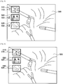
- FIG. 5 to FIG. 7 show examples of display information 500 displayed on the display units 152 and 154 of the HMD 100. In these examples, there are four users each wearing the HMD 100 and the processor unit 200 performs display control of each HMD 100.
- thumbnails of information that other users are viewing for example, as shown in FIG. 5 .
- information selected by relevant user in the present embodiment, camera image of the endoscope device 10.
- thumbnails 510, 520, and 530 of the pieces of information that the other users are viewing are displayed in part of the display region.
- the thumbnails 510, 520, and 530 are arranged and displayed in a row, for example, at the end part so as not to block the display of the main display information 500.
- identifiers 512, 522, and 532 corresponding to the thumbnails 510, 520, and 530, respectively, so as to indicate that on which HMD 100 each thumbnail is displayed.
- the identifiers 512, 522, and 532 are associated with the HMDs 100 and users who use the HMDs 100 in advance, thus making it possible for the user to grasp who is viewing which image by recognizing the relationship of correspondence in advance.
- the user wearing the HMD 100 with an identifier "1" views the same camera image of the endoscope device 10 as the image that the user views and the user wearing the HMD 100 with an identifier "2" views external image showing peripheral environment.
- the user wearing the HMD 100 with an identifier "3" views image (e.g., echo image) acquired by another medical instrument.
- image e.g., echo image
- the upper thumbnail 510 is information that an operator views
- the middle thumbnail 520 is information that a person who operates the camera of the endoscope (scopist) views
- the lower thumbnail 530 is information that an assistant views. In this manner, by explicitly displaying the roles, it is possible to present information to the user in an easy-to-understand manner.
- charts 540, 550, and 560 may also be possible to display charts 540, 550, and 560 as objects that represent pieces of information the other users view as shown in FIG. 7 in place of the thumbnails 510, 520, and 530.
- the charts 540 and 550 in FIG. 7 indicate that the users view the image by the camera of the endoscope device 10 and the chart 560 indicates that the user views the image by the image capturing unit 112 provided on the main body unit 110 of the HMD 100.
- the charts 540, 550, and 560 such as those, it is possible to let the user to know what the other users view in an intuitive manner.
- the pieces of information that the other users view may be changed, for example, at timing when each user switches displays.
- the pieces of information that the other users view are displayed so as not to make the main display information 500 less easy-to-see.
- the thumbnails 510, 520, and 530 are displayed so as not to make the main display information 500 less easy-to-see.
- the method for presenting information displayed on the HMD 100 in the endoscope system 1 is described.
- the present embodiment in the circumstances where there exists a plurality of users each wearing the HMD 100, on the display units 152 and 154 of the HMD 100 of each user, pieces of information that the other users view are also displayed together with the main display information. Due to this, each user can grasp what the other users who are working in collaboration are viewing at present during the work. In such circumstances, a conversation is made and instructions are given, and therefore, it is made possible to easily establish communication between users and the occurrence of loss in cooperation etc. can be avoided.
- FIG. 8 is a function block diagram showing a function configuration of the HMD 100 and the processor unit 200 constituting the endoscope system 1 according to the present embodiment.
- FIG. 8 shows only the function units that function when display control of the display units 152 and 154 of the HMD 100 is performed, but it is assumed that other function units are included actually.
- the processor unit 200 functions as the display control device that performs display control of the two HMDs 100A and 100B and switches information that is presented to each HMD based on instructions to switch displays of each of the HMDs 100A and 100B.
- the configuration of the endoscope system 1 according to the present embodiment differs from the configuration of the first embodiment shown in FIG. 4 in that the HMD 100 includes a visual line detection unit 167.
- the other function units are the same as those of the first embodiment, and therefore, description of these function units is omitted.
- the visual line detection unit 167 provided in the HMD 100 detects the visual line of a user wearing the HMD 100.
- the visual line detection unit 167 captures an image of the eyes of the user wearing the HMD 100 and detects the visual line from the positional relationship between a reference point and a moving point in the eyes.
- the visual line of the user detected by the visual line detection unit 167 is output to the processor unit 200.
- the visual line detection unit 167 By detecting the visual line of the user by the visual line detection unit 167, for example, it is possible to grasp whether or not the user views the display units 152 and 154 of the HMD 100.
- the visual line detection unit 167 By detecting the visual line of the user by the visual line detection unit 167, for example, it is possible to grasp whether or not the user views the display units 152 and 154 of the HMD 100.
- the visual line detection unit 167 By detecting the visual line of the user by the visual line detection unit 167, for example, it is possible to grasp whether or not the user views the display units 152 and 154 of the HMD 100.
- the visual line detection unit 167 By detecting the visual line of the user by the visual line detection unit 167, for example, it is possible to grasp whether or not the user views the display units 152 and 154 of the HMD 100.
- PinP Picture In Picture
- the user moves his/her visual line to gaze the information in each display region.
- recognition will also differ between the users.
- the information that a user visually recognizes is not necessarily limited to the main information displayed on the display units 152 and 154 of the HMD 100.
- Information that a user visually recognizes includes, for example, information when the user views his/her hand(s) and information in one of display regions in the case where a plurality of display regions exists in the display units 152 and 154, other than the main information displayed on the display units 152 and 154. Consequently, as in the present embodiment, the visual line detection unit 167 is provided in the HMD 100 and information that a user visually recognizes is specified from the visual line of the user. Due to this, it is made possible to more exactly notify another user of the information that the user views, and therefore, it is possible to improve the communication between the users.
- the method for presenting information displayed on the HMD 100 in the endoscope system 1 is described.
- pieces of information that the other users view are also displayed on the display units 152 and 154 of the HMD 100 of each user together with the main display information.
- the visual line of the user wearing the HMD 100 also, it is possible to more exactly recognize the information the user views. Due to this, it is made possible for each user to grasp what the other users who are working in collaboration are viewing during the work. In such circumstances, a conversation is made and instructions are given, and therefore, it is made possible to easily establish communication between users and the occurrence of the loss in cooperation can be avoided.
- the present disclosure is not limited to those examples.
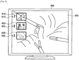
- the information that each user views may be displayed also on the display 300 connected to the processor unit 200.
- main display information 600 and information that each user wearing the HMD 100 views may be displayed on the display 300.
- the display 300 is made use of, for example, mainly as a display device that a worker not wearing the HMD 100 views of the workers who are working in collaboration. It is difficult to recognize what the worker wearing the HMD 100 is viewing during his/her work from outside. Consequently, by displaying information that the worker wearing the HMD 100 is viewing on the display, it is made possible for the worker not wearing the HMD 100 also to recognize the information that the worker wearing the HMD 100 is viewing. Due to this, it is possible to more easily establish communication between the workers.
- the main display information 600 set in advance such as camera image of the endoscope device 10
- the main display information 600 set in advance is displayed in the entire display region and at the same time, pieces of information that the persons each wearing the HMD 100 view are displayed in part of the display region.
- the pieces of information that the persons each wearing the HMD 100 may be displayed as thumbnails 610, 620, and 630 of relevant information as shown in FIG. 5 .
- identifiers 612, 622, and 632 may also be displayed so that it is known on which HMD 100, the displayed information is displayed.
- the identifiers 612, 622, and 632 are associated with the HMDs 100 and the users who use the HMDs 100 in advance and by recognizing the relationship of correspondence, the user can grasp who views which image.
- the display of the display 300 may be a display in which information that a person wearing the HMD 100 views is displayed as an object or text information as shown in FIG. 6 or FIG. 7 other than the example. Further, as information for identifying a person who views the information, the role or user name may be displayed other than the identifier.
- the display control unit configured to control the information displayed on the HMD 100 or the display 300 is provided in the processor unit 200, but the present technology is not limited to those examples. For example, it may also be possible to provide all or part of the functions of the display control unit in each HMD 100.
- the organic EL element is used as the display element, but the present technology is not limited to those examples.
- a liquid crystal display element LCD may be used as the display element.
- the endoscope system 1 is taken as an example and communication between workers during the operation is described, but the present technology can be applied to other circumstances.
- the present technology can be applied to a game that is played among a plurality of users each wearing the HMD 100.
Landscapes
- Health & Medical Sciences (AREA)
- Engineering & Computer Science (AREA)
- Life Sciences & Earth Sciences (AREA)
- Surgery (AREA)
- Medical Informatics (AREA)
- Public Health (AREA)
- Biomedical Technology (AREA)
- General Health & Medical Sciences (AREA)
- Nuclear Medicine, Radiotherapy & Molecular Imaging (AREA)
- Veterinary Medicine (AREA)
- Animal Behavior & Ethology (AREA)
- Heart & Thoracic Surgery (AREA)
- Molecular Biology (AREA)
- Physics & Mathematics (AREA)
- Pathology (AREA)
- Optics & Photonics (AREA)
- Human Computer Interaction (AREA)
- Oral & Maxillofacial Surgery (AREA)
- General Physics & Mathematics (AREA)
- Theoretical Computer Science (AREA)
- Biophysics (AREA)
- Radiology & Medical Imaging (AREA)
- Robotics (AREA)
- Epidemiology (AREA)
- Primary Health Care (AREA)
- General Engineering & Computer Science (AREA)
- Urology & Nephrology (AREA)
- Business, Economics & Management (AREA)
- General Business, Economics & Management (AREA)
- Endoscopes (AREA)
- Digital Computer Display Output (AREA)
Claims (12)
- System (1), das Folgendes umfasst:mehrere Anzeigen (100), wobei jede Anzeige eine Hauptkörpereinheit (110), die ein Abschnitt ist, der beide Augen eines Benutzers bedeckt, und Anzeigeeinheiten (152, 154), die sich vor dem linken und dem rechten Auge des Benutzers befinden, umfasst, wobei die Anzeigen (100) so konfiguriert sind, dass sie von jedem der mehreren Benutzer, die an einer Operation beteiligt sind, verwendet werden können, undeine Schaltung (200, 213), die konfiguriert ist, auf der Basis von Informationen, die jeder der mehreren Benutzer in der Operation sieht, Anzeigedaten (510, 520, 530, 610, 620, 630) zu erzeugen, die von jeder der mehreren Anzeigen (100) angezeigt werden können, wobei die Schaltung konfiguriert ist, Informationen zu ermitteln, die ein Benutzer, der eine der Anzeigen verwendet, sieht, indem eine Blicklinie des Benutzers detektiert wird.
- System nach Anspruch 1, wobei
die Schaltung so konfiguriert ist, dass sie als wenigstens einen Teil der Anzeigedaten Hauptinformationen, die durch eine empfangene Benutzereingabe ausgewählt werden, für eine Anzeige durch eine erste der mehreren Anzeigen erzeugt. - System nach Anspruch 1, wobei
die Schaltung so konfiguriert ist, dass sie als wenigstens einen Teil der Anzeigedaten, die durch eine erste der Anzeigen angezeigt werden, die konfiguriert ist, von einem der Benutzer, der an der Operation beteiligt ist, verwendet zu werden, ein Objekt erzeugt, das Informationen entspricht, die ein weiterer der Benutzer in der Operation sieht. - System nach Anspruch 3, wobei
das Objekt ein Vorschaubild ist, das einem Teil der Informationen entspricht, die durch die weitere der Anzeigen angezeigt werden. - System nach Anspruch 3, wobei
das Objekt ein Teil von Textinformationen ist, die einem Teil der Informationen entsprechen, die der weitere der Benutzer in der Operation sieht. - System nach Anspruch 3, wobei
das Objekt ein Diagramm ist, das einem Teil der Informationen entspricht, die der weitere der Benutzer in der Operation sieht. - System nach Anspruch 3, wobei
die Anzeigedaten Identifikationsinformationen umfassen, die einen weiteren der Benutzer identifizieren. - System nach Anspruch 2, wobei
die Schaltung so konfiguriert ist, dass sie als wenigstens einen Teil der Anzeigedaten, die durch eine erste der Anzeigen angezeigt werden, die konfiguriert ist, von einem der Benutzer, der an der Operation beteiligt ist, verwendet zu werden, eine Nachricht erzeugt, die anzeigt, dass sich ein Teil der Informationen, die ein weiterer der Benutzer in der Operation sieht, geändert hat. - System nach Anspruch 1, wobei
die Schaltung so konfiguriert ist, dass sie zweite Anzeigedaten erzeugt, die durch eine Anzeigevorrichtung (300) angezeigt werden, die ein Benutzer, der die Anzeige (100) nicht verwendet, sehen kann. - System nach Anspruch 1, wobei
die Informationen einen Gesichtswinkel umfassen, unter dem ein Benutzer, der die wenigstens eine der mehreren Anzeigen verwendet, wenigstens eine der Hände des Benutzers an einem Operationsort sieht. - System nach Anspruch 1, wobei
die Informationen ein Bild umfassen, das durch eine Endoskopvorrichtung (10) aufgenommen wurde. - Operationsendoskopsystem (1), das Folgendes umfasst:das System nach Anspruch 1;die Schaltung (200, 213), die mit jeder der Anzeigen kommunikationstechnisch verbunden ist und so konfiguriert ist, dass sie Informationen steuert, die auf jeder der Anzeigen angezeigt werden; undeine Endoskopvorrichtung (10), die mit der Schaltung kommunikationstechnisch verbunden ist.
Applications Claiming Priority (2)
| Application Number | Priority Date | Filing Date | Title |
|---|---|---|---|
| JP2014032008A JP6264087B2 (ja) | 2014-02-21 | 2014-02-21 | 表示制御装置、表示装置および表示制御システム |
| PCT/JP2015/000673 WO2015125447A1 (en) | 2014-02-21 | 2015-02-13 | Display control device, display device and surgical endoscopic system |
Publications (2)
| Publication Number | Publication Date |
|---|---|
| EP3107474A1 EP3107474A1 (de) | 2016-12-28 |
| EP3107474B1 true EP3107474B1 (de) | 2019-09-18 |
Family
ID=52672287
Family Applications (1)
| Application Number | Title | Priority Date | Filing Date |
|---|---|---|---|
| EP15709758.5A Active EP3107474B1 (de) | 2014-02-21 | 2015-02-13 | Mehrfachanzeigesteuerungsvorrichtung für ein chirurgisches system |
Country Status (4)
| Country | Link |
|---|---|
| US (1) | US10874284B2 (de) |
| EP (1) | EP3107474B1 (de) |
| JP (1) | JP6264087B2 (de) |
| WO (1) | WO2015125447A1 (de) |
Families Citing this family (42)
| Publication number | Priority date | Publication date | Assignee | Title |
|---|---|---|---|---|
| US10013808B2 (en) | 2015-02-03 | 2018-07-03 | Globus Medical, Inc. | Surgeon head-mounted display apparatuses |
| CA3016604A1 (en) * | 2016-03-12 | 2017-09-21 | Philipp K. Lang | Devices and methods for surgery |
| AU2017236893A1 (en) | 2016-03-21 | 2018-09-06 | Washington University | Virtual reality or augmented reality visualization of 3D medical images |
| CN106385587B (zh) * | 2016-09-14 | 2019-08-02 | 三星电子(中国)研发中心 | 分享虚拟现实视角的方法、装置及系统 |
| CN110914789A (zh) * | 2017-05-16 | 2020-03-24 | 皇家飞利浦有限公司 | 用于协同介入的增强现实 |
| JP6996883B2 (ja) * | 2017-07-05 | 2022-01-17 | ソニー・オリンパスメディカルソリューションズ株式会社 | 医療用観察装置 |
| EP3705024B1 (de) * | 2017-10-31 | 2025-07-02 | FUJIFILM Corporation | Inspektionshilfsvorrichtung, endoskopvorrichtung, inspektionshilfsverfahren und inspektionshilfsprogramm |
| US20190254753A1 (en) | 2018-02-19 | 2019-08-22 | Globus Medical, Inc. | Augmented reality navigation systems for use with robotic surgical systems and methods of their use |
| JP7353886B2 (ja) * | 2019-09-18 | 2023-10-02 | Hoya株式会社 | 内視鏡及び内視鏡システム |
| US12133772B2 (en) | 2019-12-10 | 2024-11-05 | Globus Medical, Inc. | Augmented reality headset for navigated robotic surgery |
| US11992373B2 (en) | 2019-12-10 | 2024-05-28 | Globus Medical, Inc | Augmented reality headset with varied opacity for navigated robotic surgery |
| US12220176B2 (en) | 2019-12-10 | 2025-02-11 | Globus Medical, Inc. | Extended reality instrument interaction zone for navigated robotic |
| WO2021150921A1 (en) | 2020-01-22 | 2021-07-29 | Photonic Medical Inc | Open view, multi-modal, calibrated digital loupe with depth sensing |
| US11464581B2 (en) | 2020-01-28 | 2022-10-11 | Globus Medical, Inc. | Pose measurement chaining for extended reality surgical navigation in visible and near infrared spectrums |
| US11382699B2 (en) | 2020-02-10 | 2022-07-12 | Globus Medical Inc. | Extended reality visualization of optical tool tracking volume for computer assisted navigation in surgery |
| US11207150B2 (en) | 2020-02-19 | 2021-12-28 | Globus Medical, Inc. | Displaying a virtual model of a planned instrument attachment to ensure correct selection of physical instrument attachment |
| CN111314686B (zh) * | 2020-03-20 | 2021-06-25 | 深圳市博盛医疗科技有限公司 | 一种自动优化3d立体感的方法、系统及介质 |
| US11607277B2 (en) | 2020-04-29 | 2023-03-21 | Globus Medical, Inc. | Registration of surgical tool with reference array tracked by cameras of an extended reality headset for assisted navigation during surgery |
| US11510750B2 (en) | 2020-05-08 | 2022-11-29 | Globus Medical, Inc. | Leveraging two-dimensional digital imaging and communication in medicine imagery in three-dimensional extended reality applications |
| US11153555B1 (en) | 2020-05-08 | 2021-10-19 | Globus Medical Inc. | Extended reality headset camera system for computer assisted navigation in surgery |
| US11382700B2 (en) | 2020-05-08 | 2022-07-12 | Globus Medical Inc. | Extended reality headset tool tracking and control |
| US11737831B2 (en) | 2020-09-02 | 2023-08-29 | Globus Medical Inc. | Surgical object tracking template generation for computer assisted navigation during surgical procedure |
| US11883022B2 (en) | 2020-10-02 | 2024-01-30 | Cilag Gmbh International | Shared situational awareness of the device actuator activity to prioritize certain aspects of displayed information |
| US11877897B2 (en) | 2020-10-02 | 2024-01-23 | Cilag Gmbh International | Situational awareness of instruments location and individualization of users to control displays |
| US12484897B2 (en) | 2020-10-02 | 2025-12-02 | Cilag Gmbh International | Surgical instrument with adaptive configuration control |
| US11672534B2 (en) | 2020-10-02 | 2023-06-13 | Cilag Gmbh International | Communication capability of a smart stapler |
| US11748924B2 (en) * | 2020-10-02 | 2023-09-05 | Cilag Gmbh International | Tiered system display control based on capacity and user operation |
| US11877792B2 (en) | 2020-10-02 | 2024-01-23 | Cilag Gmbh International | Smart energy combo control options |
| US12580072B2 (en) | 2020-10-02 | 2026-03-17 | Cilag Gmbh International | Cloud analytics packages |
| US12064293B2 (en) | 2020-10-02 | 2024-08-20 | Cilag Gmbh International | Field programmable surgical visualization system |
| US11883052B2 (en) | 2020-10-02 | 2024-01-30 | Cilag Gmbh International | End effector updates |
| US11830602B2 (en) | 2020-10-02 | 2023-11-28 | Cilag Gmbh International | Surgical hub having variable interconnectivity capabilities |
| US11963683B2 (en) | 2020-10-02 | 2024-04-23 | Cilag Gmbh International | Method for operating tiered operation modes in a surgical system |
| US11992372B2 (en) | 2020-10-02 | 2024-05-28 | Cilag Gmbh International | Cooperative surgical displays |
| US12016566B2 (en) | 2020-10-02 | 2024-06-25 | Cilag Gmbh International | Surgical instrument with adaptive function controls |
| US12472032B2 (en) | 2020-10-02 | 2025-11-18 | Cilag Gmbh International | Monitoring of user visual gaze to control which display system displays the primary information |
| US12213801B2 (en) | 2020-10-02 | 2025-02-04 | Cilag Gmbh International | Surgical visualization and particle trend analysis system |
| US11911030B2 (en) | 2020-10-02 | 2024-02-27 | Cilag Gmbh International | Communication capability of a surgical device with component |
| US20220104896A1 (en) * | 2020-10-02 | 2022-04-07 | Ethicon Llc | Interactive information overlay on multiple surgical displays |
| US12108931B2 (en) * | 2020-10-14 | 2024-10-08 | Covidien Lp | Medical device imaging systems and methods |
| US12324708B2 (en) * | 2021-02-17 | 2025-06-10 | Derek Duong | Augmented reality dental surgery |
| JP2023172084A (ja) * | 2022-05-23 | 2023-12-06 | キヤノン株式会社 | 情報処理装置、頭部装着型表示装置、情報処理方法、およびプログラム |
Family Cites Families (21)
| Publication number | Priority date | Publication date | Assignee | Title |
|---|---|---|---|---|
| JP3262849B2 (ja) * | 1992-08-14 | 2002-03-04 | オリンパス光学工業株式会社 | 立体像観察システムおよび内視鏡画像観察システム |
| JP2001104331A (ja) | 1999-10-06 | 2001-04-17 | Olympus Optical Co Ltd | 医療用顔面装着型映像表示装置 |
| JP2001117046A (ja) | 1999-10-22 | 2001-04-27 | Shimadzu Corp | 視線検出機能付ヘッドマウントディスプレイシステム |
| WO2003042968A1 (en) * | 2001-11-14 | 2003-05-22 | The Henry M. Jackson Foundation | Method and system for presenting real time physiological information through a head mounted display |
| JP4065507B2 (ja) | 2002-07-31 | 2008-03-26 | キヤノン株式会社 | 情報提示装置および情報処理方法 |
| JP5245257B2 (ja) * | 2006-11-22 | 2013-07-24 | ソニー株式会社 | 画像表示システム、表示装置、表示方法 |
| WO2009005901A2 (en) | 2007-05-18 | 2009-01-08 | The Uab Research Foundation | Virtual interactive presence systems and methods |
| JP2009095598A (ja) | 2007-10-19 | 2009-05-07 | Mitaka Koki Co Ltd | ヘッドマウント型双眼ルーペ装置 |
| JP2010250789A (ja) | 2008-06-10 | 2010-11-04 | Akira Tomono | カメラ付き表示装置 |
| KR101038417B1 (ko) * | 2009-02-11 | 2011-06-01 | 주식회사 이턴 | 수술 로봇 시스템 및 그 제어 방법 |
| US20110046459A1 (en) * | 2009-06-15 | 2011-02-24 | O2 Medtech, Inc. | Non-Invasive Patient Monitoring Using Near Infrared Spectrophotometry |
| JP5423716B2 (ja) * | 2011-03-30 | 2014-02-19 | ブラザー工業株式会社 | ヘッドマウントディスプレイ |
| US8832233B1 (en) * | 2011-07-20 | 2014-09-09 | Google Inc. | Experience sharing for conveying communication status |
| JP5730177B2 (ja) * | 2011-11-21 | 2015-06-03 | 独立行政法人国立がん研究センター | 電子内視鏡システム |
| JP5966510B2 (ja) * | 2012-03-29 | 2016-08-10 | ソニー株式会社 | 情報処理システム |
| US9019174B2 (en) | 2012-10-31 | 2015-04-28 | Microsoft Technology Licensing, Llc | Wearable emotion detection and feedback system |
| US9710968B2 (en) * | 2012-12-26 | 2017-07-18 | Help Lightning, Inc. | System and method for role-switching in multi-reality environments |
| EP2951811A4 (de) * | 2013-01-03 | 2016-08-17 | Meta Co | Digitale brillenvorrichtungen für extramissive räumliche bildgebung, verfahren und systeme zur virtuellen oder vergrösserten sicht, manipulation, erzeugung oder interaktion mit objekten, materialien, oder anderen einheiten |
| EP2956814A1 (de) * | 2013-02-14 | 2015-12-23 | Seiko Epson Corporation | Kopfmontierte anzeige und steuerungsverfahren für kopfmontierte anzeige |
| CA3157218A1 (en) * | 2013-03-11 | 2014-10-09 | Magic Leap, Inc. | System and method for augmented and virtual reality |
| US10042598B2 (en) * | 2013-07-16 | 2018-08-07 | Seiko Epson Corporation | Information processing apparatus, information processing method, and information processing system |
-
2014
- 2014-02-21 JP JP2014032008A patent/JP6264087B2/ja not_active Expired - Fee Related
-
2015
- 2015-02-13 US US15/118,344 patent/US10874284B2/en not_active Expired - Fee Related
- 2015-02-13 EP EP15709758.5A patent/EP3107474B1/de active Active
- 2015-02-13 WO PCT/JP2015/000673 patent/WO2015125447A1/en not_active Ceased
Non-Patent Citations (1)
| Title |
|---|
| None * |
Also Published As
| Publication number | Publication date |
|---|---|
| US20170172381A1 (en) | 2017-06-22 |
| EP3107474A1 (de) | 2016-12-28 |
| WO2015125447A1 (en) | 2015-08-27 |
| JP2015156889A (ja) | 2015-09-03 |
| JP6264087B2 (ja) | 2018-01-24 |
| US10874284B2 (en) | 2020-12-29 |
Similar Documents
| Publication | Publication Date | Title |
|---|---|---|
| EP3107474B1 (de) | Mehrfachanzeigesteuerungsvorrichtung für ein chirurgisches system | |
| US10854168B2 (en) | Information processing apparatus, information processing method, and information processing system | |
| JP6574939B2 (ja) | 表示制御装置、表示制御方法、表示制御システムおよび頭部装着ディスプレイ | |
| US11819273B2 (en) | Augmented and extended reality glasses for use in surgery visualization and telesurgery | |
| US12062430B2 (en) | Surgery visualization theatre | |
| US12462924B2 (en) | AXR visualization system | |
| CN103323948B (zh) | 头戴式显示器 | |
| US9898662B2 (en) | Information processing apparatus, information processing method, and information processing system | |
| US9507155B2 (en) | Head-mounted display | |
| US11094283B2 (en) | Head-wearable presentation apparatus, method for operating the same, and medical-optical observation system | |
| JP2018182570A (ja) | 視線情報共有方法および視線情報共有システム | |
| KR101203921B1 (ko) | 안구 추적과 위치 기반 서비스를 이용한 정보 제공 장치 | |
| US10139624B2 (en) | Head mounted display, control device, and control method | |
| WO2021226134A1 (en) | Surgery visualization theatre | |
| JP6617766B2 (ja) | 医療用観察システム、表示制御システムおよび表示制御装置 | |
| JP2019101293A (ja) | 頭部装着型表示装置、表示システム及び表示方法 | |
| EP4146115A1 (de) | Operationsvisualisierungstheater |
Legal Events
| Date | Code | Title | Description |
|---|---|---|---|
| STAA | Information on the status of an ep patent application or granted ep patent |
Free format text: STATUS: THE INTERNATIONAL PUBLICATION HAS BEEN MADE |
|
| PUAI | Public reference made under article 153(3) epc to a published international application that has entered the european phase |
Free format text: ORIGINAL CODE: 0009012 |
|
| STAA | Information on the status of an ep patent application or granted ep patent |
Free format text: STATUS: REQUEST FOR EXAMINATION WAS MADE |
|
| 17P | Request for examination filed |
Effective date: 20160713 |
|
| AK | Designated contracting states |
Kind code of ref document: A1 Designated state(s): AL AT BE BG CH CY CZ DE DK EE ES FI FR GB GR HR HU IE IS IT LI LT LU LV MC MK MT NL NO PL PT RO RS SE SI SK SM TR |
|
| AX | Request for extension of the european patent |
Extension state: BA ME |
|
| DAX | Request for extension of the european patent (deleted) | ||
| STAA | Information on the status of an ep patent application or granted ep patent |
Free format text: STATUS: EXAMINATION IS IN PROGRESS |
|
| 17Q | First examination report despatched |
Effective date: 20180321 |
|
| GRAP | Despatch of communication of intention to grant a patent |
Free format text: ORIGINAL CODE: EPIDOSNIGR1 |
|
| STAA | Information on the status of an ep patent application or granted ep patent |
Free format text: STATUS: GRANT OF PATENT IS INTENDED |
|
| INTG | Intention to grant announced |
Effective date: 20181120 |
|
| GRAJ | Information related to disapproval of communication of intention to grant by the applicant or resumption of examination proceedings by the epo deleted |
Free format text: ORIGINAL CODE: EPIDOSDIGR1 |
|
| STAA | Information on the status of an ep patent application or granted ep patent |
Free format text: STATUS: EXAMINATION IS IN PROGRESS |
|
| INTC | Intention to grant announced (deleted) | ||
| GRAP | Despatch of communication of intention to grant a patent |
Free format text: ORIGINAL CODE: EPIDOSNIGR1 |
|
| STAA | Information on the status of an ep patent application or granted ep patent |
Free format text: STATUS: GRANT OF PATENT IS INTENDED |
|
| INTG | Intention to grant announced |
Effective date: 20190410 |
|
| GRAS | Grant fee paid |
Free format text: ORIGINAL CODE: EPIDOSNIGR3 |
|
| GRAA | (expected) grant |
Free format text: ORIGINAL CODE: 0009210 |
|
| STAA | Information on the status of an ep patent application or granted ep patent |
Free format text: STATUS: THE PATENT HAS BEEN GRANTED |
|
| AK | Designated contracting states |
Kind code of ref document: B1 Designated state(s): AL AT BE BG CH CY CZ DE DK EE ES FI FR GB GR HR HU IE IS IT LI LT LU LV MC MK MT NL NO PL PT RO RS SE SI SK SM TR |
|
| REG | Reference to a national code |
Ref country code: GB Ref legal event code: FG4D |
|
| REG | Reference to a national code |
Ref country code: CH Ref legal event code: EP |
|
| REG | Reference to a national code |
Ref country code: DE Ref legal event code: R096 Ref document number: 602015038181 Country of ref document: DE |
|
| REG | Reference to a national code |
Ref country code: AT Ref legal event code: REF Ref document number: 1180397 Country of ref document: AT Kind code of ref document: T Effective date: 20191015 |
|
| REG | Reference to a national code |
Ref country code: IE Ref legal event code: FG4D |
|
| REG | Reference to a national code |
Ref country code: NL Ref legal event code: FP |
|
| PG25 | Lapsed in a contracting state [announced via postgrant information from national office to epo] |
Ref country code: FI Free format text: LAPSE BECAUSE OF FAILURE TO SUBMIT A TRANSLATION OF THE DESCRIPTION OR TO PAY THE FEE WITHIN THE PRESCRIBED TIME-LIMIT Effective date: 20190918 Ref country code: NO Free format text: LAPSE BECAUSE OF FAILURE TO SUBMIT A TRANSLATION OF THE DESCRIPTION OR TO PAY THE FEE WITHIN THE PRESCRIBED TIME-LIMIT Effective date: 20191218 Ref country code: HR Free format text: LAPSE BECAUSE OF FAILURE TO SUBMIT A TRANSLATION OF THE DESCRIPTION OR TO PAY THE FEE WITHIN THE PRESCRIBED TIME-LIMIT Effective date: 20190918 Ref country code: LT Free format text: LAPSE BECAUSE OF FAILURE TO SUBMIT A TRANSLATION OF THE DESCRIPTION OR TO PAY THE FEE WITHIN THE PRESCRIBED TIME-LIMIT Effective date: 20190918 Ref country code: BG Free format text: LAPSE BECAUSE OF FAILURE TO SUBMIT A TRANSLATION OF THE DESCRIPTION OR TO PAY THE FEE WITHIN THE PRESCRIBED TIME-LIMIT Effective date: 20191218 Ref country code: SE Free format text: LAPSE BECAUSE OF FAILURE TO SUBMIT A TRANSLATION OF THE DESCRIPTION OR TO PAY THE FEE WITHIN THE PRESCRIBED TIME-LIMIT Effective date: 20190918 |
|
| REG | Reference to a national code |
Ref country code: LT Ref legal event code: MG4D |
|
| PG25 | Lapsed in a contracting state [announced via postgrant information from national office to epo] |
Ref country code: AL Free format text: LAPSE BECAUSE OF FAILURE TO SUBMIT A TRANSLATION OF THE DESCRIPTION OR TO PAY THE FEE WITHIN THE PRESCRIBED TIME-LIMIT Effective date: 20190918 Ref country code: GR Free format text: LAPSE BECAUSE OF FAILURE TO SUBMIT A TRANSLATION OF THE DESCRIPTION OR TO PAY THE FEE WITHIN THE PRESCRIBED TIME-LIMIT Effective date: 20191219 Ref country code: LV Free format text: LAPSE BECAUSE OF FAILURE TO SUBMIT A TRANSLATION OF THE DESCRIPTION OR TO PAY THE FEE WITHIN THE PRESCRIBED TIME-LIMIT Effective date: 20190918 Ref country code: RS Free format text: LAPSE BECAUSE OF FAILURE TO SUBMIT A TRANSLATION OF THE DESCRIPTION OR TO PAY THE FEE WITHIN THE PRESCRIBED TIME-LIMIT Effective date: 20190918 |
|
| REG | Reference to a national code |
Ref country code: AT Ref legal event code: MK05 Ref document number: 1180397 Country of ref document: AT Kind code of ref document: T Effective date: 20190918 |
|
| PG25 | Lapsed in a contracting state [announced via postgrant information from national office to epo] |
Ref country code: RO Free format text: LAPSE BECAUSE OF FAILURE TO SUBMIT A TRANSLATION OF THE DESCRIPTION OR TO PAY THE FEE WITHIN THE PRESCRIBED TIME-LIMIT Effective date: 20190918 Ref country code: IT Free format text: LAPSE BECAUSE OF FAILURE TO SUBMIT A TRANSLATION OF THE DESCRIPTION OR TO PAY THE FEE WITHIN THE PRESCRIBED TIME-LIMIT Effective date: 20190918 Ref country code: PL Free format text: LAPSE BECAUSE OF FAILURE TO SUBMIT A TRANSLATION OF THE DESCRIPTION OR TO PAY THE FEE WITHIN THE PRESCRIBED TIME-LIMIT Effective date: 20190918 Ref country code: AT Free format text: LAPSE BECAUSE OF FAILURE TO SUBMIT A TRANSLATION OF THE DESCRIPTION OR TO PAY THE FEE WITHIN THE PRESCRIBED TIME-LIMIT Effective date: 20190918 Ref country code: PT Free format text: LAPSE BECAUSE OF FAILURE TO SUBMIT A TRANSLATION OF THE DESCRIPTION OR TO PAY THE FEE WITHIN THE PRESCRIBED TIME-LIMIT Effective date: 20200120 Ref country code: ES Free format text: LAPSE BECAUSE OF FAILURE TO SUBMIT A TRANSLATION OF THE DESCRIPTION OR TO PAY THE FEE WITHIN THE PRESCRIBED TIME-LIMIT Effective date: 20190918 Ref country code: EE Free format text: LAPSE BECAUSE OF FAILURE TO SUBMIT A TRANSLATION OF THE DESCRIPTION OR TO PAY THE FEE WITHIN THE PRESCRIBED TIME-LIMIT Effective date: 20190918 |
|
| PG25 | Lapsed in a contracting state [announced via postgrant information from national office to epo] |
Ref country code: CZ Free format text: LAPSE BECAUSE OF FAILURE TO SUBMIT A TRANSLATION OF THE DESCRIPTION OR TO PAY THE FEE WITHIN THE PRESCRIBED TIME-LIMIT Effective date: 20190918 Ref country code: SM Free format text: LAPSE BECAUSE OF FAILURE TO SUBMIT A TRANSLATION OF THE DESCRIPTION OR TO PAY THE FEE WITHIN THE PRESCRIBED TIME-LIMIT Effective date: 20190918 Ref country code: IS Free format text: LAPSE BECAUSE OF FAILURE TO SUBMIT A TRANSLATION OF THE DESCRIPTION OR TO PAY THE FEE WITHIN THE PRESCRIBED TIME-LIMIT Effective date: 20200224 Ref country code: SK Free format text: LAPSE BECAUSE OF FAILURE TO SUBMIT A TRANSLATION OF THE DESCRIPTION OR TO PAY THE FEE WITHIN THE PRESCRIBED TIME-LIMIT Effective date: 20190918 |
|
| REG | Reference to a national code |
Ref country code: DE Ref legal event code: R097 Ref document number: 602015038181 Country of ref document: DE |
|
| PLBE | No opposition filed within time limit |
Free format text: ORIGINAL CODE: 0009261 |
|
| STAA | Information on the status of an ep patent application or granted ep patent |
Free format text: STATUS: NO OPPOSITION FILED WITHIN TIME LIMIT |
|
| PG2D | Information on lapse in contracting state deleted |
Ref country code: IS |
|
| PG25 | Lapsed in a contracting state [announced via postgrant information from national office to epo] |
Ref country code: DK Free format text: LAPSE BECAUSE OF FAILURE TO SUBMIT A TRANSLATION OF THE DESCRIPTION OR TO PAY THE FEE WITHIN THE PRESCRIBED TIME-LIMIT Effective date: 20190918 Ref country code: IS Free format text: LAPSE BECAUSE OF FAILURE TO SUBMIT A TRANSLATION OF THE DESCRIPTION OR TO PAY THE FEE WITHIN THE PRESCRIBED TIME-LIMIT Effective date: 20200119 |
|
| 26N | No opposition filed |
Effective date: 20200619 |
|
| PG25 | Lapsed in a contracting state [announced via postgrant information from national office to epo] |
Ref country code: SI Free format text: LAPSE BECAUSE OF FAILURE TO SUBMIT A TRANSLATION OF THE DESCRIPTION OR TO PAY THE FEE WITHIN THE PRESCRIBED TIME-LIMIT Effective date: 20190918 |
|
| REG | Reference to a national code |
Ref country code: CH Ref legal event code: PL |
|
| REG | Reference to a national code |
Ref country code: BE Ref legal event code: MM Effective date: 20200229 |
|
| PG25 | Lapsed in a contracting state [announced via postgrant information from national office to epo] |
Ref country code: LU Free format text: LAPSE BECAUSE OF NON-PAYMENT OF DUE FEES Effective date: 20200213 Ref country code: MC Free format text: LAPSE BECAUSE OF FAILURE TO SUBMIT A TRANSLATION OF THE DESCRIPTION OR TO PAY THE FEE WITHIN THE PRESCRIBED TIME-LIMIT Effective date: 20190918 |
|
| PG25 | Lapsed in a contracting state [announced via postgrant information from national office to epo] |
Ref country code: LI Free format text: LAPSE BECAUSE OF NON-PAYMENT OF DUE FEES Effective date: 20200229 Ref country code: CH Free format text: LAPSE BECAUSE OF NON-PAYMENT OF DUE FEES Effective date: 20200229 |
|
| PG25 | Lapsed in a contracting state [announced via postgrant information from national office to epo] |
Ref country code: IE Free format text: LAPSE BECAUSE OF NON-PAYMENT OF DUE FEES Effective date: 20200213 |
|
| PG25 | Lapsed in a contracting state [announced via postgrant information from national office to epo] |
Ref country code: BE Free format text: LAPSE BECAUSE OF NON-PAYMENT OF DUE FEES Effective date: 20200229 |
|
| PG25 | Lapsed in a contracting state [announced via postgrant information from national office to epo] |
Ref country code: FR Free format text: LAPSE BECAUSE OF NON-PAYMENT OF DUE FEES Effective date: 20200302 |
|
| PG25 | Lapsed in a contracting state [announced via postgrant information from national office to epo] |
Ref country code: TR Free format text: LAPSE BECAUSE OF FAILURE TO SUBMIT A TRANSLATION OF THE DESCRIPTION OR TO PAY THE FEE WITHIN THE PRESCRIBED TIME-LIMIT Effective date: 20190918 Ref country code: MT Free format text: LAPSE BECAUSE OF FAILURE TO SUBMIT A TRANSLATION OF THE DESCRIPTION OR TO PAY THE FEE WITHIN THE PRESCRIBED TIME-LIMIT Effective date: 20190918 Ref country code: CY Free format text: LAPSE BECAUSE OF FAILURE TO SUBMIT A TRANSLATION OF THE DESCRIPTION OR TO PAY THE FEE WITHIN THE PRESCRIBED TIME-LIMIT Effective date: 20190918 |
|
| PG25 | Lapsed in a contracting state [announced via postgrant information from national office to epo] |
Ref country code: MK Free format text: LAPSE BECAUSE OF FAILURE TO SUBMIT A TRANSLATION OF THE DESCRIPTION OR TO PAY THE FEE WITHIN THE PRESCRIBED TIME-LIMIT Effective date: 20190918 |
|
| P01 | Opt-out of the competence of the unified patent court (upc) registered |
Effective date: 20230527 |
|
| PGFP | Annual fee paid to national office [announced via postgrant information from national office to epo] |
Ref country code: NL Payment date: 20240123 Year of fee payment: 10 |
|
| PGFP | Annual fee paid to national office [announced via postgrant information from national office to epo] |
Ref country code: DE Payment date: 20240123 Year of fee payment: 10 Ref country code: GB Payment date: 20240123 Year of fee payment: 10 |
|
| REG | Reference to a national code |
Ref country code: DE Ref legal event code: R119 Ref document number: 602015038181 Country of ref document: DE |
|
| REG | Reference to a national code |
Ref country code: NL Ref legal event code: MM Effective date: 20250301 |
|
| GBPC | Gb: european patent ceased through non-payment of renewal fee |
Effective date: 20250213 |
|
| PG25 | Lapsed in a contracting state [announced via postgrant information from national office to epo] |
Ref country code: NL Free format text: LAPSE BECAUSE OF NON-PAYMENT OF DUE FEES Effective date: 20250301 |
|
| PG25 | Lapsed in a contracting state [announced via postgrant information from national office to epo] |
Ref country code: DE Free format text: LAPSE BECAUSE OF NON-PAYMENT OF DUE FEES Effective date: 20250902 |
|
| PG25 | Lapsed in a contracting state [announced via postgrant information from national office to epo] |
Ref country code: GB Free format text: LAPSE BECAUSE OF NON-PAYMENT OF DUE FEES Effective date: 20250213 |