EP3107338A1 - Method and arrangement in a cellular communications system - Google Patents
Method and arrangement in a cellular communications system Download PDFInfo
- Publication number
- EP3107338A1 EP3107338A1 EP16173214.4A EP16173214A EP3107338A1 EP 3107338 A1 EP3107338 A1 EP 3107338A1 EP 16173214 A EP16173214 A EP 16173214A EP 3107338 A1 EP3107338 A1 EP 3107338A1
- Authority
- EP
- European Patent Office
- Prior art keywords
- power
- sub
- frame
- parameter
- mask
- Prior art date
- Legal status (The legal status is an assumption and is not a legal conclusion. Google has not performed a legal analysis and makes no representation as to the accuracy of the status listed.)
- Withdrawn
Links
- 238000000034 method Methods 0.000 title claims abstract description 44
- 230000010267 cellular communication Effects 0.000 title 1
- 230000008054 signal transmission Effects 0.000 claims abstract description 45
- 230000005540 biological transmission Effects 0.000 claims abstract description 19
- 230000001413 cellular effect Effects 0.000 claims abstract description 12
- 238000004904 shortening Methods 0.000 claims description 3
- 238000004891 communication Methods 0.000 abstract description 3
- 230000001052 transient effect Effects 0.000 description 11
- 230000011664 signaling Effects 0.000 description 8
- 230000006978 adaptation Effects 0.000 description 5
- 230000008901 benefit Effects 0.000 description 4
- 230000008859 change Effects 0.000 description 3
- 238000010586 diagram Methods 0.000 description 3
- 230000001419 dependent effect Effects 0.000 description 2
- 230000000694 effects Effects 0.000 description 2
- 230000006870 function Effects 0.000 description 2
- 230000007704 transition Effects 0.000 description 2
- 241000760358 Enodes Species 0.000 description 1
- 230000002411 adverse Effects 0.000 description 1
- 238000004364 calculation method Methods 0.000 description 1
- 239000000969 carrier Substances 0.000 description 1
- 230000015556 catabolic process Effects 0.000 description 1
- 238000004590 computer program Methods 0.000 description 1
- 238000006731 degradation reaction Methods 0.000 description 1
- 230000007774 longterm Effects 0.000 description 1
- 238000005259 measurement Methods 0.000 description 1
- 238000010295 mobile communication Methods 0.000 description 1
- 230000010363 phase shift Effects 0.000 description 1
- 230000007480 spreading Effects 0.000 description 1
Images


Classifications
-
- H—ELECTRICITY
- H04—ELECTRIC COMMUNICATION TECHNIQUE
- H04W—WIRELESS COMMUNICATION NETWORKS
- H04W52/00—Power management, e.g. TPC [Transmission Power Control], power saving or power classes
- H04W52/04—TPC
- H04W52/30—TPC using constraints in the total amount of available transmission power
- H04W52/36—TPC using constraints in the total amount of available transmission power with a discrete range or set of values, e.g. step size, ramping or offsets
-
- H—ELECTRICITY
- H03—ELECTRONIC CIRCUITRY
- H03G—CONTROL OF AMPLIFICATION
- H03G3/00—Gain control in amplifiers or frequency changers
- H03G3/20—Automatic control
- H03G3/30—Automatic control in amplifiers having semiconductor devices
- H03G3/3036—Automatic control in amplifiers having semiconductor devices in high-frequency amplifiers or in frequency-changers
- H03G3/3042—Automatic control in amplifiers having semiconductor devices in high-frequency amplifiers or in frequency-changers in modulators, frequency-changers, transmitters or power amplifiers
- H03G3/3047—Automatic control in amplifiers having semiconductor devices in high-frequency amplifiers or in frequency-changers in modulators, frequency-changers, transmitters or power amplifiers for intermittent signals, e.g. burst signals
-
- H—ELECTRICITY
- H04—ELECTRIC COMMUNICATION TECHNIQUE
- H04L—TRANSMISSION OF DIGITAL INFORMATION, e.g. TELEGRAPHIC COMMUNICATION
- H04L27/00—Modulated-carrier systems
- H04L27/26—Systems using multi-frequency codes
-
- H—ELECTRICITY
- H04—ELECTRIC COMMUNICATION TECHNIQUE
- H04W—WIRELESS COMMUNICATION NETWORKS
- H04W52/00—Power management, e.g. TPC [Transmission Power Control], power saving or power classes
- H04W52/04—TPC
- H04W52/18—TPC being performed according to specific parameters
-
- H—ELECTRICITY
- H04—ELECTRIC COMMUNICATION TECHNIQUE
- H04L—TRANSMISSION OF DIGITAL INFORMATION, e.g. TELEGRAPHIC COMMUNICATION
- H04L27/00—Modulated-carrier systems
- H04L27/26—Systems using multi-frequency codes
- H04L27/2601—Multicarrier modulation systems
- H04L27/2626—Arrangements specific to the transmitter only
Definitions
- the present invention relates to the area of wireless communication, and especially to a method and an arrangement for transmission output power control in a cellular telecommunications network.
- UTRAN Universal Terrestrial Radio Access Network
- UMTS Universal Mobile Telecommunications System
- the UTRAN consists of Radio Network Controllers (RNCs) and NodeBs i.e. radio base stations.
- RNCs Radio Network Controllers
- NodeBs communicate wirelessly with mobile user equipments (UEs) and the RNCs control the NodeBs.
- the RNCs are further connected to the Core Network (CN).
- Evolved UTRAN Evolved UTRAN (E-UTRAN) is an evolution of the UTRAN towards a high-data rate, low-latency and packet-optimised radio access network.
- E-UTRAN consists of e-NodeBs (evolved NodeBs), and the e-NodeBs are interconnected and further connected to the Evolved Packet Core network (EPC).
- E-UTRAN is also being referred to as Long Term Evolution (LTE) and is standardized within the 3 rd Generation Partnership Project (3GPP).
- a transmitter In a time multiplexed system, e.g. the uplink in E-UTRAN, HSPA (High Speed Packet Access) or GSM (Global System for Mobile communications) the transmitters transmit in certain assigned timeslots. Thus, a transmitter will start transmitting in the beginning of the timeslot and turn off the transmitter at the end of the timeslot. In addition it is possible that the output power of the transmitter may change from timeslot to timeslot or within a timeslot.
- HSPA High Speed Packet Access
- GSM Global System for Mobile communications
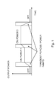
- Transmitters typically require some time for turning on the output power as well as turning off the output power. This means that the turning on and off the output power does not occur instantaneously. Furthermore, very sharp transitions between on state and off state would cause unwanted signal emissions in the adjacent carriers causing adjacent channel interference, which should be limited to certain level. Thus, there exists a transient period, i.e. when the transmitter switches from the off state to the on state or vice versa. During these transient periods the output signal of the transmitter is undefined in the sense that the quality of the signal is not as good as when the transmitter is fully turned on. The transient periods are illustrated in figure 1 . Furthermore, the output power during the transient period is referred to as a power ramp.
- the duration of the ramping is typically quite short compared to the length of the sub-frame or timeslot but its position has an influence on system performance.
- ramping or transient position there are three possibilities:
- a power mask also referred to as a time mask, defines for example the allowed output power at given time instants during a transient event and the time when a ramp starts. For example when the transmitter ramps up, i.e. increases the output power, the power mask may specify how much output power is allowed before the transient event, during the transient event and after the transient event and additionally, when the ramp-up should start.
- the allowed output power may be expressed as an open range, i.e. below a specific level or as an interval, i.e. between output power X and Y.
- the power masks are defined in timeslot level (577 ⁇ s and 667 ⁇ s respectively).
- E-UTRAN it will be defined on sub-frame level (1 ms) and SC-OFDM (Single Carrier-Orthogonal Frequency-Division Multiplexing) symbol level, e.g. to be applied when a Sounding Reference Symbol (SRS) is transmitted in the sub-frame.
- SRS Sounding Reference Symbol
- the power control operates on timeslot level. This means that power change occurs on timeslot basis and the transmit power mask is consequently defined on timeslot basis. Moreover, in E-UTRAN the power control operates on sub-frame basis and therefore the transmit power mask is defined on sub-frame level and OFDM symbol level.
- the duration of a sub-frame is 1 ms.
- the sub-frame consists of 14 or 12 SC-OFDM symbols.
- the last symbol in the sub-frame could be used for transmitting the SRS that is used for channel estimation purposes.
- the SRS can also be used for performing uplink channel dependent scheduling and time tracking.
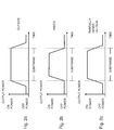
- the transmit power for the SRS may differ from the transmit power used for the other symbols of the sub-frame.
- the relationship of the different transmit powers is illustrated in figure 3 . However, it should be noted that the abrupt power changes shown in figure 3 are not possible to implement.
- the uplink timeslots are placed adjacent to each other in time.
- one set of fixed well defined ramped up and down periods are defined in the standard 3GPP TS 25.101 and TS 25.102.
- the tradeoff between signal quality and interference to other timeslots is set when the system is designed.
- Figure 4 illustrates that placement of power ramps causes problems with signal quality degradation due to non-constant output power and with interference to a user.
- certain signals e.g. the sounding reference symbol (SRS)
- SRS sounding reference symbol
- the interference due to power ramping needs to be minimized in respect to other signals such as data symbols in order to maximize throughput.
- a method for transmission output power control in a cellular telecommunications network is provided.
- a pre-defined power mask for at least one of a sub-frame and an OFDM symbol of a signal transmission is set.
- the power mask is defined by at least one parameter associated with any of the following:
- an arrangement for transmission output power control in a cellular telecommunications network comprises a unit for setting a pre-defined power mask for at least one of a sub-frame and an OFDM symbol of a signal transmission.
- the power mask is defined by at least one parameter associated with any of the following:
- An advantage with the present invention is the possibility to signal certain transmission signals, i.e. the reference signal, from a user with a high quality, while at the same time it is possible to minimize the interference to and from other users.
- the throughput of the system can be kept high.
- Another advantage with the present invention is the possibility to differentiate the quality of a service for different users.
- the present invention comprises methods and arrangements for transmission output power control in a cellular telecommunications network as illustrated in figure 5 .
- the improved transmission output power control is achieved according to an embodiment by adapting a pre-defined power mask to a signal transmission characteristic of the signal transmission, i.e. content of the signal to be transmitted, and applying the adapted power mask to a sub-frame or an OFDM symbol.
- the method could further be implemented in a network node such as an eNodeB or in a UE.
- a power mask is the transient period of the transmission power between transmit OFF and ON power and between transmit ON and OFF power and is defined by one or several power mask parameters.
- An example of a power mask is shown in figure 6a .
- the power mask comprises a first power ramp and a second power ramp.
- the first power ramp has a starting point and an ending point.
- the second power ramp has a starting point and an ending point.
- the power mask is defined by duration of the first power ramp and duration of the second power ramp in this example.
- the power mask could further be defined by a first power level and a second power level at a specific time of the ramps.
- Figure 7a illustrates a flowchart showing a method according to a first embodiment of the present invention where a pre-defined power mask is set 70 for a sub-frame or an OFDM symbol of a signal transmission to be applied in the signal transmission. This may be done by using a pre-defined power mask.
- a pre-defined power mask is defined by one or several power mask parameters as previously mentioned.
- One or several power mask parameters are then adapted 72 to a signal transmission characteristic of the signal transmission.
- the present invention provides the possibility to adapt the power mask parameters according to one or more of a plurality of signal transmission characteristics such as
- the adapted power mask is then applied 74 to the sub-frame or the OFDM symbol when the sub-frame or OFDM symbol is transmitted.
- the change in the output power i.e. the time instant to turn on or off a transmitter which transmits the signal on which the power mask is applied, and thus the position of the ramp of the power mask, is determined by a single or a combination of the signal transmission characteristics.
- the adaptation of the pre-defined power mask can be realized in different ways, e.g. as standardized rules or by configuration via signaling.
- the standardized rules are utilized in order to determine when to start or end the ramp as well as the duration of the ramp.
- FIG 8 an example of a set of rules for how to adapt the power mask parameter is illustrated.
- Each arrow 81-87 represents a rule.
- a first state box 810 represents the signal transmission characteristic of the signal transmission when a sub-frame or symbol contains data.
- a second state box 820 represents the signal transmission characteristic of the signal transmission when the content of a sub-frame or symbol is a control or reference symbol.
- a third state box 830 represents the signal transmission characteristic of the signal transmission when a sub-frame or symbol contains no data. For example this could be when the UE is in an OFF state.
- the UE can be in both idle mode and connected mode in the OFF state.
- the signal transmission characteristic of the signal transmission could also be a transition from one sub-frame or symbol to a successive sub-frame or symbol.
- Each rule is associated with one or several parameters of the power mask ramps, i.e. the starting point, the ending point and duration.
- the power mask parameters may be defined in the standard or be signaled by the core network 52, as illustrated in figure 5 .
- the adaptation of the power mask parameters may also be determined by signal transmission characteristic of the signal transmission such as network configuration, e.g. scheduling information.
- scheduling information is sent in a cell by the base station i.e. the eNodeB.
- PDCCH Physical Downlink Control Channel
- Every UE is supposed to listen to the scheduling information sent on PDCCH since any UE in the cell can be scheduled for uplink transmission in any sub-frame.
- the scheduling information indicates which sub-frames are used and which ones are not. By listening to the scheduling information the UE can determine if the sub-frame following the sub-frame the UE is scheduled for, i.e. the succcessive sub-frame, will be used by another UE or not.
- the UE can then adapt the position of the ramp based on this information.
- the rule 84 could imply that the adapting of the power mask parameter is performed by adjusting the starting point parameter of the second power ramp to be placed outside the sub-frame as shown in figure 9a .
- the rule 85 could imply that the adapting of the power mask parameter is performed by adjusting the ending point parameter of the second power ramp to be placed inside the sub-frame as shown in figure 9b .
- the rule 81 comprises the adapting of the power mask parameter performed by adjusting the starting point parameter of the second power ramp to be placed inside the sub-frame and by adjusting the ending point parameter of the second power ramp to be placed outside the sub-frame and by shortening the duration of the second power ramp as illustrated in figure 9c .
- the rule 83, 86 comprises the adapting of the power mask parameter performed by adjusting the ending point parameter of the first power ramp to be placed outside the OFDM symbol and by adjusting the starting point parameter of the second power ramp to be placed outside the OFDM symbol as illustrated in figure 9d .
- the rule 83, 86 comprises the adapting of the power mask parameter performed by adjusting the starting point parameter of the first power ramp to be placed inside the OFDM symbol as shown in figure 9e .
- the rule 82, 87 comprises the adapting of the power mask parameter performed by adjusting the ending point parameter of the second power ramp to be placed inside the OFDM symbol.
- a further example is when a successive sub-frame of the sub-frame to be transmitted contains data with high order modulation, e.g. 16 QAM (Quadrature Amplitude Modulation) or 64 QAM or higher.
- the rule comprises the adapting of the power mask parameter performed by adjusting the ending point parameter of the second power ramp to be placed inside the sub-frame.
- a successive sub-frame of the sub-frame to be transmitted contains data with low order modulation, e.g. BPSK (Binary Phase-Shift Keying) or QPSK (Quadrature PSK)
- the rule comprises the adapting of the power mask parameter performed by adjusting the starting point parameter of the second power ramp to be placed outside the sub-frame.
- a threshold value of the signal disturbance during the signal transmission could be determined.
- the rule comprises the adapting of the power mask parameter performed by adjusting the ending point parameter of the first power ramp to be placed outside the sub-frame and by adjusting the starting point parameter of the second power ramp to be placed outside the sub-frame.
- the rule comprises the adapting of the power mask parameter performed by adjusting the starting point parameter of the first power ramp to be placed inside the sub-frame and by adjusting the ending point parameter of the second power ramp to be placed inside the sub-frame.
- Each eNodeB schedules the UEs connected to the eNodeB. Furthermore, as the eNodeBs are interconnected they can exchange scheduling information. Consequently, the eNodeBs can exchange information regarding whether a sub-frame will be scheduled or not.
- eNodeB in principle could identify if the successive sub-frame is used or not used by another eNodeB. This is because the eNodeBs are interconnected and they can exchange via eNode B-eNode B interface, the scheduling information or at least information regarding whether successive sub-frame will be scheduled or not. The eNodeB knows if the successive sub-frame is used or not used by another eNodeB as the eNodeBs are interconnected.
- the adaptation of the pre-defined power mask can be realized by dynamic configuration via signaling.
- a power mask utilized by a base station i.e. an eNodeB
- the RNC could configure the base station power mask via signaling over an interface between the RNC and the NodeB i.e. Iub.
- the adaptation of the power mask utilized in the UE may also be based on explicit radio interface signaling.
- the signaling can be sent via a broadcast channel from the eNodeB in case the same adapted power mask is to be used by all UEs in a cell with certain signal transmission characteristics e.g. a certain power mask in a large cell.
- each UE can be individually configured to transmit according to a certain power mask via RRC (Radio Resource Control) or MAC (Media Access Control) signaling.
- Figure 7b illustrates an embodiment of the present invention implemented in the UE 54, wherein the UE 54 receives instructions 76 from the eNodeB on how to adapt the pre-defined power mask.
- An advantage with the embodiment is that the power consumption of the UE 54 is reduced since the calculations of how to adapt the power mask is executed in the eNodeB.
- Another advantage with the embodiment is that the system performance can be maximised due to the fact that the eNodeB has more information about the system state, e.g. queue lengths, radio conditions, than the UE.
- the eNodeB signals the exact time offset from the edge of the sub-frame or the OFDM symbol. In another embodiment the eNodeB signals that either all ramps start at the end or at the beginning of the sub-frame or the OFDM symbol. Yet in another embodiment the eNodeB signals the identifier of an adapted power mask of a plurality of specified and well defined adapted power masks to the UE, i.e. an identity of a standardized power mask out of plurality of standardized power masks. In all the above cases the power mask utilized by the UE is dynamically or semi-statically configured and controlled by the eNodeB.
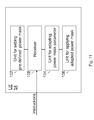
- the method shown in figure 7a may be implemented in an arrangement illustrated in figure 10 .
- the arrangement 100 comprises a unit for setting 102 a pre-defined power mask for a sub-frame or an OFDM symbol of a signal transmission.
- the arrangement 100 further comprises a unit for adapting 104 at least one of the power mask parameters of the power mask to a signal transmission characteristic of the signal transmission, and a unit for applying 106 the adapted power mask to the sub-frame or the OFDM symbol.
- the unit for adapting 104 the power mask parameter is configured to adjust the power mask parameters in accordance with the method of the present invention described previously.
- the arrangement 100 could be implemented in a UE 54 or an eNodeB 50.
- the arrangement is implemented in a UE 54 as shown in figure 11 .
- the arrangement could further comprise a receiver 108 for receiving instructions on how to adapt the power mask parameters from the eNodeB 50.
- a method for transmission output power control in a cellular telecommunications network comprising: setting (70) a pre-defined power mask for at least one of a sub-frame and an Orthogonal Frequency-Division Multiplexing, OFDM, symbol of a signal transmission, wherein the power mask is defined by at least one parameter associated with any of the following: a starting point of a first power ramp, an ending point of the first power ramp, a starting point of a second power ramp, an ending point of the second power ramp, a first and second duration of the first and second power ramps, respectively, and a first and second power level at a specific time of the first and second power ramps, respectively, wherein the method comprises the steps of:
- the adapting (72) of the power mask parameter is performed by adjusting the ending point parameter of the second power ramp to be placed inside said sub-frame when a successive sub-frame of said sub-frame contains data.
- the adapting (72) of the power mask parameter is performed by adjusting the starting point parameter of the second power ramp to be placed outside said sub-frame when a successive sub-frame of said sub-frame does not contain data.
- the adapting (72) of the power mask parameter is performed by adjusting the starting point parameter of the second power ramp to be placed inside said sub-frame and by adjusting the ending point parameter of the second power ramp to be placed outside said sub-frame and by shortening the duration of the second power ramp when said sub-frame contains data and a successive sub-frame of said sub-frame contains data.
- the adapting (72) of the power mask parameter is performed by adjusting the ending point parameter of the first power ramp to be placed outside said OFDM symbol and by adjusting the starting point parameter of the second power ramp to be placed outside said OFDM symbol when said OFDM symbol contains a reference signal.
- the adapting (72) of the power mask parameter is performed by adjusting the starting point parameter of the first power ramp to be placed inside said OFDM symbol when a preceding OFDM symbol of said OFDM symbol contains a reference signal.
- the adapting (72) of the power mask parameter is performed by adjusting the ending point parameter of the second power ramp to be placed inside said OFDM symbol when a successive OFDM symbol of said OFDM symbol contains a reference signal.
- the adapting (72) of the power mask parameter is performed by adjusting the ending point parameter of the second power ramp to be placed inside said sub-frame when a successive sub-frame of said sub-frame contains data with high order modulation.
- the adapting (72) of the power mask parameter is performed by adjusting the starting point parameter of the second power ramp to be placed outside said sub-frame when a successive sub-frame of said sub-frame contains data with low order modulation.
- the adapting (72) of the power mask parameter is performed by adjusting the ending point parameter of the first power ramp to be placed outside said sub-frame and by adjusting the starting point parameter of the second power ramp to be placed outside said sub-frame when a signal disturbance is lower or equal to a pre-determined threshold value.
- the adapting (72) of the power mask parameter is performed by adjusting the starting point parameter of the first power ramp to be placed inside said sub-frame and by adjusting the ending point parameter of the second power ramp to be placed inside said sub-frame when a signal disturbance is greater than a pre-determined threshold value.
- an arrangement for transmission output power control in a cellular telecommunications network comprising:
- an arrangement according to aspect 17 comprising a receiver for receiving instruction (108) on how to adapt the at least one of the at least one power mask parameter from a network node (50).
- the unit for adapting (104) is configured to adjust the ending point parameter of the second power ramp to be placed inside said sub-frame when a successive sub-frame of said sub-frame contains data.
- the unit for adapting (104) is configured to adjust the starting point parameter of the second power ramp to be placed outside said sub-frame when a successive sub-frame of said sub-frame does not contain data.
- the unit for adapting (104) is configured to adjust the starting point parameter of the second power ramp to be placed inside said sub-frame and to adjust the ending point parameter of the second power ramp to be placed outside said sub-frame and to shorten the duration of the second power ramp when said sub-frame contains data and a successive sub-frame of said sub-frame contains data.
- the unit for adapting (104) is configured to adjust the ending point parameter of the first power ramp to be placed outside said OFDM symbol and to adjust the starting point parameter of the second power ramp to be placed outside said OFDM symbol when said OFDM symbol contains a reference signal.
- the unit for adapting (104) is configured to adjust the starting point parameter of the first power ramp to be placed inside said OFDM symbol when a preceding OFDM symbol of said OFDM symbol contains a reference signal.
- the unit for adapting (104) is configured to adjust the ending point parameter of the second power ramp to be placed inside said OFDM symbol when a successive OFDM symbol of said OFDM symbol contains a reference signal.
- the unit for adapting (104) is configured to adjust the ending point parameter of the second power ramp to be placed inside said sub-frame when a successive sub-frame of said sub-frame contains data with high order modulation.
- the unit for adapting (104) is configured to adjust the starting point parameter of the second power ramp to be placed outside said sub-frame when a successive sub-frame of said sub-frame contains data with low order modulation.
- the unit for adapting (104) is configured to adjust the ending point parameter of the first power ramp to be placed outside said sub-frame and to adjust the starting point parameter of the second power ramp to be placed outside said sub-frame when a signal disturbance is lower or equal to a pre-determined threshold value.
- the unit for adapting (104) is configured to adjust the starting point parameter of the first power ramp to be placed inside said sub-frame and to adjust the ending point parameter of the second power ramp to be placed inside said sub-frame when a signal disturbance is greater than a pre-determined threshold value.
Landscapes
- Engineering & Computer Science (AREA)
- Computer Networks & Wireless Communication (AREA)
- Signal Processing (AREA)
- Mobile Radio Communication Systems (AREA)
- Transmitters (AREA)
Applications Claiming Priority (3)
| Application Number | Priority Date | Filing Date | Title |
|---|---|---|---|
| US5916508P | 2008-06-05 | 2008-06-05 | |
| EP11184349.6A EP2405695B1 (en) | 2008-06-05 | 2008-12-18 | Method and arrangement in a cellular communications system |
| EP08874563.3A EP2301285B2 (en) | 2008-06-05 | 2008-12-18 | Method and arrangement in a cellular communications system |
Related Parent Applications (2)
| Application Number | Title | Priority Date | Filing Date |
|---|---|---|---|
| EP11184349.6A Division EP2405695B1 (en) | 2008-06-05 | 2008-12-18 | Method and arrangement in a cellular communications system |
| EP08874563.3A Division EP2301285B2 (en) | 2008-06-05 | 2008-12-18 | Method and arrangement in a cellular communications system |
Publications (1)
| Publication Number | Publication Date |
|---|---|
| EP3107338A1 true EP3107338A1 (en) | 2016-12-21 |
Family
ID=40512202
Family Applications (3)
| Application Number | Title | Priority Date | Filing Date |
|---|---|---|---|
| EP16173214.4A Withdrawn EP3107338A1 (en) | 2008-06-05 | 2008-12-18 | Method and arrangement in a cellular communications system |
| EP11184349.6A Active EP2405695B1 (en) | 2008-06-05 | 2008-12-18 | Method and arrangement in a cellular communications system |
| EP08874563.3A Active EP2301285B2 (en) | 2008-06-05 | 2008-12-18 | Method and arrangement in a cellular communications system |
Family Applications After (2)
| Application Number | Title | Priority Date | Filing Date |
|---|---|---|---|
| EP11184349.6A Active EP2405695B1 (en) | 2008-06-05 | 2008-12-18 | Method and arrangement in a cellular communications system |
| EP08874563.3A Active EP2301285B2 (en) | 2008-06-05 | 2008-12-18 | Method and arrangement in a cellular communications system |
Country Status (22)
| Country | Link |
|---|---|
| US (2) | US8223863B2 (pl) |
| EP (3) | EP3107338A1 (pl) |
| JP (10) | JP4951718B2 (pl) |
| KR (1) | KR101530411B1 (pl) |
| CN (2) | CN102057732B (pl) |
| AT (1) | ATE536069T1 (pl) |
| AU (1) | AU2008357514B2 (pl) |
| BR (1) | BRPI0822643B1 (pl) |
| CA (1) | CA2726818A1 (pl) |
| CO (1) | CO6351839A2 (pl) |
| ES (2) | ES2375532T5 (pl) |
| HK (2) | HK1157992A1 (pl) |
| IL (1) | IL209597A (pl) |
| MA (1) | MA32447B1 (pl) |
| MX (1) | MX2010012233A (pl) |
| MY (1) | MY149743A (pl) |
| NZ (1) | NZ588998A (pl) |
| PL (1) | PL2301285T5 (pl) |
| RU (1) | RU2010154440A (pl) |
| TW (3) | TWI635766B (pl) |
| WO (1) | WO2009148372A1 (pl) |
| ZA (1) | ZA201008047B (pl) |
Families Citing this family (9)
| Publication number | Priority date | Publication date | Assignee | Title |
|---|---|---|---|---|
| KR101530411B1 (ko) * | 2008-06-05 | 2015-06-19 | 옵티스 와이어리스 테크놀로지, 엘엘씨 | 셀룰러 통신 시스템에서의 방법 및 장치 |
| WO2013125925A1 (ko) * | 2012-02-24 | 2013-08-29 | 엘지전자 주식회사 | 동기를 트랙킹하는 방법 및 장치 |
| US9763225B2 (en) * | 2013-10-07 | 2017-09-12 | Qualcomm Incorporated | LTE-U clear channel assessment operations |
| US9295010B2 (en) * | 2013-10-11 | 2016-03-22 | Qualcomm Incorporated | Dynamic transmit power and signal shaping |
| US9742443B2 (en) * | 2015-09-08 | 2017-08-22 | Nxp B.V. | Pulse shaping for radio frequency transmitters |
| WO2017142469A1 (en) * | 2016-02-17 | 2017-08-24 | Telefonaktiebolaget Lm Ericsson (Publ) | Systems and methods of providing a guard interval for transmissions in a communication system |
| WO2018083659A1 (en) * | 2016-11-04 | 2018-05-11 | Telefonaktiebolaget L M Ericsson (Publ) | On/off time mask for short tti |
| US10368365B2 (en) | 2017-02-02 | 2019-07-30 | Qualcomm Incorporated | Time mask techniques for shortened transmission time intervals |
| JP7027118B2 (ja) | 2017-10-24 | 2022-03-01 | 株式会社Ihiプラント | タンク用ジャッキサポート及びタンクの構築方法 |
Citations (3)
| Publication number | Priority date | Publication date | Assignee | Title |
|---|---|---|---|---|
| US6625227B1 (en) * | 1999-09-30 | 2003-09-23 | Ericsson Inc. | Artificial ramping of transmit power for burst transmissions |
| WO2006102922A1 (en) * | 2005-03-30 | 2006-10-05 | Freescale Semiconductor, Inc. | Method and device for transmitting a sequence of transmission bursts |
| US7158494B2 (en) * | 2001-10-22 | 2007-01-02 | Matsushita Electric Industrial Co., Ltd. | Multi-mode communications transmitter |
Family Cites Families (18)
| Publication number | Priority date | Publication date | Assignee | Title |
|---|---|---|---|---|
| US8089323B2 (en) * | 2006-08-05 | 2012-01-03 | Min Ming Tarng | Green technology: green circuit and device designs of green chip |
| US6430402B1 (en) * | 1998-09-14 | 2002-08-06 | Conexant Systems, Inc. | Power amplifier saturation prevention method, apparatus, and communication system incorporating the same |
| US7031677B2 (en) * | 2001-06-29 | 2006-04-18 | Infineon Technologies Ag | Optimization of the operating point of power amplifiers in mobile stations |
| JP2003152565A (ja) * | 2001-11-13 | 2003-05-23 | Matsushita Electric Ind Co Ltd | 送信装置および送信方法 |
| US7215972B2 (en) * | 2003-12-09 | 2007-05-08 | Freescale Semiconductor, Inc. | Adaptive transmit power control system |
| JP2005328572A (ja) * | 2005-07-27 | 2005-11-24 | Fujitsu Ltd | 増幅器の制御装置及びその制御方法 |
| TWI324462B (en) * | 2005-12-20 | 2010-05-01 | Via Tech Inc | A control method for producing a ramp of output power and a transmitter utilizing the same |
| JP2007221655A (ja) * | 2006-02-20 | 2007-08-30 | Oki Electric Ind Co Ltd | 無線装置およびその電力制御方法 |
| US7962108B1 (en) * | 2006-03-29 | 2011-06-14 | Rf Micro Devices, Inc. | Adaptive AM/PM compensation |
| US8467473B2 (en) * | 2006-03-31 | 2013-06-18 | Broadcom Corporation | Power control techniques for wireless transmitters |
| JP4614238B2 (ja) * | 2006-07-14 | 2011-01-19 | ルネサスエレクトロニクス株式会社 | Rf電力増幅装置 |
| US20080070510A1 (en) * | 2006-09-18 | 2008-03-20 | Nokia Corporation | Interference management techniques for wireless networks |
| US7864885B2 (en) * | 2006-11-15 | 2011-01-04 | Samsung Electronics Co., Ltd. | Multiple input multiple output (MIMO) transceiver with pooled adaptive digital filtering |
| JP4322928B2 (ja) * | 2007-02-14 | 2009-09-02 | 株式会社東芝 | 信号受信装置 |
| US7962109B1 (en) * | 2007-02-27 | 2011-06-14 | Rf Micro Devices, Inc. | Excess current and saturation detection and correction in a power amplifier |
| FI20075343A0 (fi) * | 2007-05-11 | 2007-05-11 | Nokia Corp | Lähettimen häiriönpäästön ohjaus |
| US7986738B2 (en) * | 2007-10-19 | 2011-07-26 | Redpine Signals, Inc | Peak to average power ratio reduction apparatus and method for a wireless OFDM transmitter |
| KR101530411B1 (ko) * | 2008-06-05 | 2015-06-19 | 옵티스 와이어리스 테크놀로지, 엘엘씨 | 셀룰러 통신 시스템에서의 방법 및 장치 |
-
2008
- 2008-12-18 KR KR1020117000118A patent/KR101530411B1/ko active IP Right Grant
- 2008-12-18 CN CN200880129696.0A patent/CN102057732B/zh active Active
- 2008-12-18 EP EP16173214.4A patent/EP3107338A1/en not_active Withdrawn
- 2008-12-18 MX MX2010012233A patent/MX2010012233A/es active IP Right Grant
- 2008-12-18 RU RU2010154440/07A patent/RU2010154440A/ru not_active Application Discontinuation
- 2008-12-18 EP EP11184349.6A patent/EP2405695B1/en active Active
- 2008-12-18 BR BRPI0822643-1A patent/BRPI0822643B1/pt active IP Right Grant
- 2008-12-18 CA CA2726818A patent/CA2726818A1/en not_active Abandoned
- 2008-12-18 US US12/990,502 patent/US8223863B2/en active Active
- 2008-12-18 WO PCT/SE2008/051494 patent/WO2009148372A1/en active Application Filing
- 2008-12-18 AT AT08874563T patent/ATE536069T1/de active
- 2008-12-18 CN CN201410170002.5A patent/CN103974406B/zh active Active
- 2008-12-18 MY MYPI2010005435A patent/MY149743A/en unknown
- 2008-12-18 JP JP2011512408A patent/JP4951718B2/ja active Active
- 2008-12-18 ES ES08874563.3T patent/ES2375532T5/es active Active
- 2008-12-18 NZ NZ588998A patent/NZ588998A/xx unknown
- 2008-12-18 PL PL08874563T patent/PL2301285T5/pl unknown
- 2008-12-18 EP EP08874563.3A patent/EP2301285B2/en active Active
- 2008-12-18 ES ES11184349.6T patent/ES2586383T3/es active Active
- 2008-12-18 AU AU2008357514A patent/AU2008357514B2/en active Active
-
2009
- 2009-06-04 TW TW105123658A patent/TWI635766B/zh active
- 2009-06-04 TW TW098118597A patent/TWI457028B/zh active
- 2009-06-04 TW TW103124614A patent/TWI552628B/zh active
-
2010
- 2010-11-10 ZA ZA2010/08047A patent/ZA201008047B/en unknown
- 2010-11-10 CO CO10140911A patent/CO6351839A2/es active IP Right Grant
- 2010-11-28 IL IL209597A patent/IL209597A/en active IP Right Grant
-
2011
- 2011-01-03 MA MA33482A patent/MA32447B1/fr unknown
- 2011-11-07 HK HK11112005.5A patent/HK1157992A1/xx unknown
-
2012
- 2012-03-12 JP JP2012055048A patent/JP5460765B2/ja active Active
- 2012-07-13 US US13/548,831 patent/US20120281775A1/en not_active Abandoned
-
2014
- 2014-01-14 JP JP2014004572A patent/JP5706010B2/ja active Active
-
2015
- 2015-02-02 HK HK15101086.6A patent/HK1205847A1/xx unknown
- 2015-02-25 JP JP2015035578A patent/JP5941571B2/ja active Active
-
2016
- 2016-05-20 JP JP2016101926A patent/JP6181810B2/ja active Active
-
2017
- 2017-07-20 JP JP2017141196A patent/JP6377220B2/ja active Active
-
2018
- 2018-07-24 JP JP2018138556A patent/JP6546325B2/ja active Active
-
2019
- 2019-06-12 JP JP2019109566A patent/JP6872205B2/ja active Active
-
2021
- 2021-04-09 JP JP2021066683A patent/JP7071781B2/ja active Active
-
2022
- 2022-05-02 JP JP2022076168A patent/JP2022110030A/ja active Pending
Patent Citations (3)
| Publication number | Priority date | Publication date | Assignee | Title |
|---|---|---|---|---|
| US6625227B1 (en) * | 1999-09-30 | 2003-09-23 | Ericsson Inc. | Artificial ramping of transmit power for burst transmissions |
| US7158494B2 (en) * | 2001-10-22 | 2007-01-02 | Matsushita Electric Industrial Co., Ltd. | Multi-mode communications transmitter |
| WO2006102922A1 (en) * | 2005-03-30 | 2006-10-05 | Freescale Semiconductor, Inc. | Method and device for transmitting a sequence of transmission bursts |
Non-Patent Citations (1)
| Title |
|---|
| "Digital cellular telecommunications system (Phase 2+); Radio transmission and reception (GSM 05.05 version 5.8.0); DRAFT pr ETS 300 910", IEEE, LIS, SOPHIA ANTIPOLIS CEDEX, FRANCE, vol. SMG2, no. Fifth, 1 May 1998 (1998-05-01), XP014026141, ISSN: 0000-0001 * |
Also Published As
Similar Documents
| Publication | Publication Date | Title |
|---|---|---|
| JP7071781B2 (ja) | セルラ通信システムにおける方法および装置 | |
| AU2021202799B2 (en) | Method and arrangement in a cellular communications system | |
| AU2013263845B2 (en) | Method and Arrangement in a Cellular Communications System |
Legal Events
| Date | Code | Title | Description |
|---|---|---|---|
| PUAI | Public reference made under article 153(3) epc to a published international application that has entered the european phase |
Free format text: ORIGINAL CODE: 0009012 |
|
| STAA | Information on the status of an ep patent application or granted ep patent |
Free format text: STATUS: THE APPLICATION HAS BEEN PUBLISHED |
|
| AC | Divisional application: reference to earlier application |
Ref document number: 2405695 Country of ref document: EP Kind code of ref document: P Ref document number: 2301285 Country of ref document: EP Kind code of ref document: P |
|
| AK | Designated contracting states |
Kind code of ref document: A1 Designated state(s): AT BE BG CH CY CZ DE DK EE ES FI FR GB GR HR HU IE IS IT LI LT LU LV MC MT NL NO PL PT RO SE SI SK TR |
|
| STAA | Information on the status of an ep patent application or granted ep patent |
Free format text: STATUS: REQUEST FOR EXAMINATION WAS MADE |
|
| 17P | Request for examination filed |
Effective date: 20170612 |
|
| RBV | Designated contracting states (corrected) |
Designated state(s): AT BE BG CH CY CZ DE DK EE ES FI FR GB GR HR HU IE IS IT LI LT LU LV MC MT NL NO PL PT RO SE SI SK TR |
|
| STAA | Information on the status of an ep patent application or granted ep patent |
Free format text: STATUS: EXAMINATION IS IN PROGRESS |
|
| 17Q | First examination report despatched |
Effective date: 20191022 |
|
| STAA | Information on the status of an ep patent application or granted ep patent |
Free format text: STATUS: EXAMINATION IS IN PROGRESS |
|
| STAA | Information on the status of an ep patent application or granted ep patent |
Free format text: STATUS: EXAMINATION IS IN PROGRESS |
|
| P01 | Opt-out of the competence of the unified patent court (upc) registered |
Effective date: 20230523 |
|
| STAA | Information on the status of an ep patent application or granted ep patent |
Free format text: STATUS: THE APPLICATION HAS BEEN WITHDRAWN |
|
| 18W | Application withdrawn |
Effective date: 20230925 |